RSS16 Operating instructions Safety sensor EN 1 1. About this document 1.1 Function This operating instructions manual provides all the information you need for the mounting, set-up and commissioning to ensure the safe operation and disassembly of the safety switchgear. The operating instructions must be available in a legible condition and a complete version in the vicinity of the device. 1.2 Target group: authorised qualified personnel All operations described in this operating instructions manual must be carried out by trained specialist personnel, authorised by the plant operator only. Please make sure that you have read and understood these operating instructions and that you know all applicable legislations regarding occupational safety and accident prevention prior to installation and putting the component into operation. The machine builder must carefully select the harmonised standards to be complied with as well as other technical specifications for the selection, mounting and integration of the components. 1.3 Explanation of the symbols used Information, hint, note: This symbol is used for identifying useful additional information. Caution: Failure to comply with this warning notice could lead to failures or malfunctions. Warning: Failure to comply with this warning notice could lead to physical injury and/or damage to the machine. 1.4 Appropriate use The products described in these operating instructions are developed to execute safety-related functions as part of an entire plant or machine. It is the responsibility of the manufacturer of a machine or plant to ensure the correct functionality of the entire machinery or plant. The safety switchgear must be exclusively used in accordance with the versions listed below or for the applications authorised by the manufacturer. Detailed information regarding the range of applications can be found in the chapter "Product description". 1.5 General safety instructions The user must observe the safety instructions in this operating instruc- tions manual, labelled with the caution or warning symbol above, the country-specific installation standards as well as all prevailing safety regulations and accident prevention rules. Further technical information can be found in the Schmersal catalogues or in the online catalogue on the Internet: www.schmersal.net. Content x.000 / August 2014 / v.A. - 103008722-EN / A / 2014-08-29 / AE-Nr. - 1 About this document 1.1 Function .............................................. 1 1.2 Target group: authorised qualified personnel .................. 1 1.3 Explanation of the symbols used ........................... 1 1.4 Appropriate use ........................................ 1 1.5 General safety instructions ............................... 1 1.6 Warning about misuse ................................... 2 1.7 Exclusion of liability ..................................... 2 2 Product description 2.1 Ordering code ......................................... 2 2.2 Special versions........................................ 2 2.3 Comprehensive quality insurance to 2006/42/EC .............. 2 2.4 Destination and use ..................................... 2 2.5 Technical data ......................................... 2 2.6 Safety classification ..................................... 3 3 Mounting 3.1 General mounting instructions ............................. 3 3.2 Dimensions ........................................... 4 3.3 Switching distance ...................................... 5 3.4 Adjustment ............................................ 5 3.5 Actuating curves ....................................... 5 4 Electrical connection 4.1 General information for electrical connection.................. 5 5 Operating principles and coding 5.1 Mode of operation of the safety outputs...................... 6 5.2 Coding / Actuator teach-in procedure ....................... 6 6 Diagnostic functions 6.1 Operating principle of the diagnostic LED's ................... 6 6.2 Operating principle of the electronic diagnostic output .......... 6 6.3 Safety-sensors with serial diagnostic function ................. 7 7 Set-up and maintenance 7.1 Functional testing....................................... 8 7.2 Maintenance .......................................... 8 8 Disassembly and disposal 8.1 Disassembly........................................... 8 8.2 Disposal .............................................. 8 9 Appendix 9.1 Wiring examples ....................................... 9 9.2 Wiring configuration and connector accessories .............. 10 10 Declaration of conformity 10.1 EC Declaration of conformity............................ 11 EN Operating instructions. . . . . . . . . . . .pages 1 to 12 Translation of the original operating instructions
Transcript
RSS16Operating instructionsSafety sensor
EN 1
1. About this document
1.1 FunctionThis operating instructions manual provides all the information you need for the mounting, set-up and commissioning to ensure the safe operation and disassembly of the safety switchgear. The operating instructions must be available in a legible condition and a complete version in the vicinity of the device.
1.2 Target group: authorised qualified personnelAll operations described in this operating instructions manual must be carried out by trained specialist personnel, authorised by the plant operator only.
Please make sure that you have read and understood these operating instructions and that you know all applicable legislations regarding occupational safety and accident prevention prior to installation and putting the component into operation.
The machine builder must carefully select the harmonised standards to be complied with as well as other technical specifications for the selection, mounting and integration of the components.
1.3 Explanation of the symbols used
Information, hint, note:This symbol is used for identifying useful additional information.
Caution: Failure to comply with this warning notice could lead to failures or malfunctions.Warning: Failure to comply with this warning notice could lead to physical injury and/or damage to the machine.
1.4 Appropriate useThe products described in these operating instructions are developed to execute safety-related functions as part of an entire plant or machine. It is the responsibility of the manufacturer of a machine or plant to ensure the correct functionality of the entire machinery or plant.
The safety switchgear must be exclusively used in accordance with the versions listed below or for the applications authorised by the manufacturer. Detailed information regarding the range of applications can be found in the chapter "Product description".
1.5 General safety instructionsThe user must observe the safety instructions in this operating instruc-tions manual, labelled with the caution or warning symbol above, the country-specific installation standards as well as all prevailing safety regulations and accident prevention rules.
Further technical information can be found in the Schmersal catalogues or in the online catalogue on the Internet: www.schmersal.net.
EN Operating instructions. . . . . . . . . . . .pages 1 to 12Translation of the original operating instructions
2
Operating instructionsSafety sensor RSS16
EN
The information contained in this operating instructions manual is provided without liability and is subject to technical modifications.
There are no residual risks, provided that the safety instructions as well as the instructions regarding mounting, commissioning, operation and maintenance are observed.
1.6 Warning about misuse
In case of improper use or manipulation of the safety switch-gear, personal hazards or damages to machinery or plant components cannot be excluded. The relevant requirements of the standard ISO 14119 must be observed.
1.7 Exclusion of liabilityWe shall accept no liability for damages and malfunctions resulting from defective mounting or failure to comply with this operating instructions manual. The manufacturer shall accept no liability for damages resulting from the use of unauthorised spare parts or accessories.
For safety reasons, invasive work on the device as well as arbitrary re-pairs, conversions and modifications to the device are strictly forbidden; the manufacturer shall accept no liability for damages resulting from such invasive work, arbitrary repairs, conversions and/or modifications to the device.
2. Product description
2.1 Ordering codeThis operating instructions manual applies to the following types:
RSS16-➀-➁-➂-➃No. Option Description
➀ Standard codingI1 Individual codingI2 Individual coding, re-teaching enabled
➁ D With diagnostic outputSD With serial diagnostic function
➂ Without latchingR With latching, latching force 40 … 60 N
➃ ST8H With connector plug M12 in the middleCC With cage clampsSK With screw terminals
ActuatorRST16-1 Without latchingRST16-1-R With latching, latching force 40 … 60 N
2.2 Special versionsFor special versions, which are not listed in the order code below 2.1, these specifications apply accordingly, provided that they correspond to the standard version.
2.3 Comprehensive quality insurance to 2006/42/ECSchmersal is a certified company to appendix X of the Machinery Directive. As a result, Schmersal is entitled to autonomously conduct the conformity assessment procedure for the products listed in Appendix IV of the MD without involving a notified body. The EC proto-type test certificates are available upon request or can be downloaded from the Internet at www.schmersal.com.
2.4 Destination and useThis non-contact, electronic safety sensor is designed for application in safety circuits and is used for monitoring the position of movable safety guards. In this application, the safety sensor monitors the position of hinged, sliding or removable safety guards by means of the coded electronic actuator.
The safety function consists of safely switching off the safety outputs when the safety guard is opened and maintaining the safe switched off condition of the safety outputs for as long as the safety guard is open.
Safety sensors and actuators with latching (ordering suffix -R) must always be used in pairs. The latching force (40…60 N) is exercised by the permanent magnet that keeps hatches and small guards closed, also in a de-energised condition.The system can be used as a door end stop up to 5 kg at 0.35 m/s.
The diagnostic output of the safety sensor alternatively can be used as a conventional output or as a "serial output" with input and output channel.
Series-wiringSeries-wiring can be set up . The number of components is only limited by the external cable protection according to the technical data and the line loss . Series-wiring of up to 31 RSS16- ... -SD components with serial diagnostics is possible .In devices with the serial diagnostics function (ordering suffix -SD), the serial diagnostics connections are wired in series and connected to a SD Gateway for evaluation purposes. (Wiring examples: see appendix)
Protection is not required when pilot wires are laid . However, the cables must be separated from the supply and energy cables . The max. fuse rate for a sensor chain depends on the section of the connecting cable of the sensor or the technical specifications .
The entire concept of the control system, in which the safety component is integrated, must be validated to the relevant standards.
IEC 62061, ISO 13849-1Enclosure: Plastic, glass-fibre, reinforced
thermoplastic, self-extinguishingMagnetic latching: Anchor plate and pole plates
made of stainless steel 1.4016Operating principle: RFIDActuator: RST 16-1, RST 16-1-RFixation sensor: 2 x M5, cylinder head screw - washers: recommended DIN 125A /
Form A for M5 - recommended torque for all fixing screws: 2 Nm - fixing screws connection space: Torx T10Series-wiring: Unlimited number of components,
please observe external cable protection, max. 31 components in case of serial diagnostics
(when used as door stop) for safety guards ≤ 5 kg and actuating speed ≤ 0.35 m/s
Latching force (R): - front : approx. 60 N - from above or below: approx . 40 N
3
RSS16Operating instructionsSafety sensor
EN
Switching distances to IEC 60947-5-3: Typical switching distance: 15 mmAssured switching distance sao: 12 mm - On versions with latching sao: 5 mm Assured switch-off distance sar: 30 mmHysteresis: < 2.0 mmRepeat accuracy R: < 0.5 mmAmbient conditions: Ambient temperature Tu: −25 °C … +70 °CStorage and transport temperature: −25 °C … +85 °CProtection class: IP65 / IP67 to IEC 60529 - with connector plug M12: IP65 / IP66 / IP67 to IEC 60529Resistance to vibration: 10 … 55 Hz, Amplitude 1 mmResistance to shock: 30 g / 11 msSwitching frequency f: 1 HzResponse time: - Actuator: ≤ 100 ms - Inputs: ≤ 0.5 msDuration of risk: ≤ 200 msTime to readiness: ≤ 2 sMinimum distance between adjacent sensors: 250 mmElectrical data:Rated operating voltage Ue: 24 VDC −15% / +10%
(PELV to IEC 60204-1)Rated operating current Ie: 2.1 AMinimum operating current Im: 0.5 mARequired rated short-circuit current: 100 ARated insulation voltage Ui: 32 VRated impulse withstand voltage Uimp: 800 VNo-load current Io: 45 mAOvervoltage category: IIIDegree of pollution: 3Safety inputs X1/X2:Rated operating voltage Ue1: 24 VDC −15% / +10% (PELV unit)Power consumption per input: 5 mAsafety outputs Y1/Y2: p-type, short-circuit proofRated operating current Ie1: each max. 1 A Utilisation category: DC-12, DC-13: Ue/Ie: 24 VDC / 1 A / 55°C
DC-12, DC-13: Ue/Ie: 24 VDC / 0.5 A / 65°C DC-12, DC-13: Ue/Ie: 24 VDC / 0.25 A / 70°C
Voltage drop: Ue < 1 VDiagnostic output: short-circuit proof, p-typeOperating current Ie2: max. 0,05 AUtilisation category: DC-12: Ue/Ie: 24 VDC / 0.05 A
DC-13: Ue/Ie: 24 VDC / 0.05 AVoltage drop: Ue < 2 VSerial diagnostic: short-circuit proofOperating current: 150 mAWiring capacitance: max. 50 nFExternal cable protection: fuse - with connector plug M12: 2.0 A - with cage clamps: 2.5 A - with screw terminals: 4.0 A
Please observe the cable section!
2.6 Safety classificationStandards: ISO 13849-1, IEC 61508, IEC 62061PL: eControl Category: 4PFH value: 6.3 x 10⁻¹¹ / hPFD: 1.1 x 10⁻⁵
SIL: suitable for SIL 3 applicationsService life: 20 years
3. Mounting
3.1 General mounting instructions
During fitting, the requirements of ISO 14119 must be observed.
The mounting holes allow for a mounting with M 5 screws. If using slots the sensor should be secured against slipping.
It is recommended to use the attached shims when using the securing slots or placing on a flat surface (not when actuating on the floor).
The component can be mounted in any position. The sensors have three square active surfaces: front side, nameplate side and bottom side opposite the nameplate. One of the active surfaces of the safety sensor and the actuator have to face each other. Maintaining the safe operating distance should be observed ≤ Sao and ≥ Sar.With a mounting position different to that noted in this description, the resulting switching distances have to be evaluated separately.
To avoid any interference inherent to this kind of system and any reduc-tion of the switching distances, please observe the following guidelines:• The presence of metal chips in the vicinity of the sensor is liable to
modify the switching distance.• Keep away from metal chips.• Minimum distance between two sensors: 250 mm
Actuator RST16-1-R with M5 secure countersunk head screws, slide the anchor plate from the middle to the sides, then the grave safety clip and press-in the safety pin for protection against manipulation .
The recommended tightening torque for the coupling nut of the M12 connection plug is 0.6 Nm. For versions with clamping space sealing M16 cable glands with O-ring must be used.
Safety sensor and actuator and the cover for the clamping space must be permanently fitted to the safety guards and protected against displacement by suitable measures (tamperproof screws, gluing, drilling of the screw heads).
Accessories (to be ordered separately)
Set of countersunk screws with unidirectional slots for RST16-1 and RST16-1-R• 2 pieces M5x12, ordering code 101135338 • 2 pieces M5x16, ordering code 101135339 • 2 pieces M5x20, ordering code 101135340
4
Operating instructionsSafety sensor RSS16
EN
3.2 DimensionsAll measurements in mm.
RSS16-...-R-CC / RSS16-...-R-SK
28
1.826.49.2
16
16
3052
91
24.5
¤5.5
40
16
25
6.5
30
52
39.5
RSS16-...-R-ST8H
28
1.826.49.2
30
91
13.3
1.8 39.5
24.5
¤5.5
40
13
10.8
6.5
52
30
M12x1
Actuator RST16-1-R
¤5.2
8.361
24
409
¤10
90°
RSS16-...-CC / RSS16-...-SK
2031
16
16
30
28
1.826.49.2
2952
91
24.5
¤5.516
25
6.5
30
52
RSS16-...-ST8H
20
29
31
M12x1
30
13.3
1.8
28
1.826.49.2
91
24.5
¤5.56.5
13
10.8
52
30
Actuator: RST16-1
60
6.8
40
16
5.3
Alternative suitable actuators with different design: refer to www.schmersal.net.
5
RSS16Operating instructionsSafety sensor
EN
3.3 Switching distanceInstalling the actuator centrally to the active sensor surface allows a maximum height offset (X) in close vicinity of ± 27 mm.The lateral offset (Y) is max. ± 9 mm. With the latching version the max. height offset (X) is ± 2 mm and the lateral offset (Y) is max. ± 2 mm.
X
Y
3.4 AdjustmentThe continuous signal of the yellow LED signals the actuator detection; the flashing of the yellow LED signals that the safety sensor is actuated in the hysteresis area. The correct functionality of both safety channels must be checked by means of the connected safety-monitoring module.
Recommended AdjustmentAlign the safety sensor and actuator at a distance of 0.5 x sao.
3.5 Actuating curvesThe actuating curves represent the typical switching distance of the safety sensor during the approach of the actuator subject to the actuating direction
Height misalignment
-5-20 5 10 15-15 20-10 0X [mm]
S [mm]
0
5
10
-25-30-35 25 30 35
15
X
Y
Transverse misalignment
-5-20-25 5 10 15-15 20 25-10 0Y [mm]
S [mm]
0
5
10
15
-30-35 30 35
23
X
Y
Preferred actuation directions: from front or from the X direction. With lateral travel in the Y direction be aware of the side lobes.
4. Electrical connection
4.1 General information for electrical connection
The electrical connection may only be carried out by authorised personnel in a de-energised condition.
The safety outputs can be integrated into the safety circuit of the control system. For applications of PL e / control category 4 to ISO 13849-1, the safety outputs of the safety sensor or sensor of the chain must be wired to a safety monitoring module of the same control category .
Requirements for the connected safety-monitoring module• Dual-channel safety input, suitable for p-type sensors with NO function
Information for the selection of suitable safety-monitoring modules can be found in the Schmersal catalogues or in the online catalogue on the Internet: www.schmersal.net.
As to alternative to a safety-monitoring module, the safety sensors of the CSS-F0 or. -F1 Series can be used as a first sensor of a se-ries-wired chain for the direct control and monitoring of positive action safety contactors (Refer to operating manual of CSS 34F0 / CSS 34F1)
If the safety sensor is wired to relays or to non-safety relevant control components, a new risk analysis must be carried out.
The safety sensors cyclically switch off the safety output to test them. The safety-monitoring module therefore does not need to be equipped with a cross-wire short detection. The switch-off times must be tolerated by the safety-monitoring module. The switch -off time of the safety sensor is additionally extended depending on the cable length and the capacity of the cable used. A maximum switch-off time of 250 micro-seconds is reached with a 200-m connecting cable.
Configuration of the safety-monitoring moduleIf the safety sensor is connected to electronic safety- monitoring modules, we recommend that you set a discrepancy time of 100 ms. The safety inputs of the safety-monitoring module must be able blanking a test impulse of approx. 1 ms.
Cable design in case of serial diagnostics
When wiring SD devices, please observe the voltage drop on the cables and the current carrying capacity of the individual components.
The wiring capacitance of the connecting cable of the safety sensor must not exceed 50 nF.
Depending on the beach structure, normally unshielded 200 m long control cables LIYY 0:25 mm to 1.5 mm have a wiring capacitance of approx. 20 … 50 nF .
6
Operating instructionsSafety sensor RSS16
EN
5. Operating principles and coding
5.1 Mode of operation of the safety outputsThe safety outputs can be integrated in the safety circuit of the control system. The opening of a safety guard, i.e. the actuator is removed out of the active zone of the sensor, will immediately disable the safety outputs of the sensor (switching distances refer to technical data).
Any error that does not immediately affect the functionality of the safety sensor (e.g. too high the ambient temperature, interference potential at a safety output, cross-wire short) will lead to a warning message, the disabling of the diagnostic output and the delayed shut-down of the safety outputs. The safety outputs are disabled if the error warning is active for 30 minutes.
The signal combination, diagnostic output disabled and safety channels still enabled, can be used to stop the production process in a controlled manner.
After fault rectification, the error message is reset by opening and re-closing the corresponding safety guard. The safety outputs enable and allow a restart.
For devices with serial diagnostic, a bit can be set/deleted in the call telegram to reset the fault.
5.2 Coding / Actuator teach-in procedureThe safety switchgears are classified according to ISO 14119 as type 4 switching devices. Designs with individual coding are classified as highly coded.
Safety sensors with standard coding are ready to use upon delivery.
Individually coded safety sensors and actuators will require the following "teach-in" procedure:
1. Switch the safety sensor's voltage supply off and back on.2. Introduce the actuator in the detection range. The teach-in
procedure is signalled at the safety sensor, red LED on, yellow LED flashes (1 Hz).
3. After 10 seconds, brief cyclic flashes (3 Hz) request the switch-off of the operating voltage of the safety sensor. (If the voltage is not switched off within 5 minutes, the safety sensor cancels the "teach-in" procedure and signals a false actuator by 5 red flashes).
4. After the operating voltage is switched back on, the actuator must be detected once more in order to activate the taught actuator code. In this way, the activated code is definitively saved!
For ordering suffix -I1, the thus executed allocation of safety sensor and actuator is irreversible.
For ordering suffix -I2, the "teach-in" procedure for a new actuator can be repeated an unlimited number of times . When a new actuator is taught, the code, which was applicable until the moment, becomes invalid. Subsequent to that, an enabling inhibit will be active for ten minutes, thus providing for an increased protection against tampering. The green LED will flash until the expiration of the time of the enabling inhibit and the detection of the new actuator . In case of power failure during the lapse of time, the 10-minutes tampering protection time will restart .
6. Diagnostic functions
6.1 Operating principle of the diagnostic LED'sThe safety sensor indicates the operating condition and faults by means of three-colour LED's.
The green LED indicates that the safety sensor is ready for operation. The supply voltage is on.
The yellow LED always signals the presence of an actuator within range. If the actuator is operating near the limit of the hysteresis range of the safety sensor, the yellow LED is flashing. The flashing and even 2 Hz clocking diagnostic output can be used to prematurely detect variations in the clearance between the sensor and the actuator (e.g. sagging of a safety guard). The sensor must be adjusted before the distance to the actuator increases and before the safety outputs are disabled, thus stopping the machine.
If an error is detected, the red LED will be activated.
Flash codes - Diagnostic LED's
LED indication (red) Error cause1 flash pulse Error output Y12 flash pulses Error output Y23 flash pulses Cross-wire Y1/Y24 flash pulses Ambient temperature too high5 flash pulses Incorrect or defective actuatorContinuous red Internal errorContinuous red with yellow flashing Teach-in procedure
6.2 Operating principle of the electronic diagnostic outputA diagnostic output additionally indicates the operating condition (refer to table 1). These signals can be used in a downstream control.
The short-circuit proof diagnostic output OUT can be used for central visualisation or control functions, e.g. in a PLC. It indicates the switching condition as shown in the table 1.
ErrorErrors, which no longer guarantee the function of the safety sensor (internal errors) cause the safety outputs to be disabled within the risk time. Any error that does not immediately affect the safe functionality of the safety sensor (e.g. the ambient temperature too high, interference potential at a safety output, cross-wire short) will lead to a delayed shut-down (refer to table 2).
After the rectification of the error, the error message is reset by opening the corresponding safety guard.
Error warningThe diagnostic output can also be used to detect clearance variations between the sensor and the actuator in the same way as the yellow LED. An active fault is visualised by the red LED and causes the diagnostic output to be disabled. The safety outputs are disabled after max. 30 minutes if the fault is not rectified. This signal combination, diagnostic output disabled and safety channels still enabled, can be used to stop the production process in a controlled manner.
7
RSS16Operating instructionsSafety sensor
EN
Table 1: Examples of the diagnostic function of the safety-sensor with conventional diagnostic output
Sensor function LED's Diagnostic output Safety outputs Note
Green Red Yellow Y1, Y2I. Supply voltage On Off Off 0 V 0 V Voltage on, no evaluation of the voltage qualityII. Actuated On Off On 24 V 24 V The yellow LED always signals the presence
of an actuator within rangeIII. Actuated in limit area On Off Flashes
(1 Hz)24 V
pulsed(approx. 2 Hz)
24 V The sensor must be adjusted before the distance to the actuator increases and before the safety outputs are disabled, thus stopping the machine
IV. Error warning, sensor actuated
Off Flashes On 0 V 24 V After 30 minutes if the error is not rectified
V. Error Off Flashes On 0 V 0 V Refer to table with flash codesVI. Teach target Off On Flashes 0 V 0 V Sensor in teaching modeVII. Protection time Flashes Off Off 0 V 0 V 10 minutes pause after re-teaching
6.3 Safety-sensors with serial diagnostic functionSafety sensors with serial diagnostic function have a serial input and output instead of the conventional diagnostic output. If RSS / CSS safety sensors are wired in series, the safety channels as well as the inputs and outputs of the diagnostic channels are wired in series.
Max. 31 safety switchgear with serial diagnostics can be wired in series. For the evaluation of the serial diagnostics line either the PROFIBUS- Gateway SD-I-DP-V0-2 or the Universal-Gateway SD-I-U-... are used. This SD-Gateway is integrated as a slave in an existing field bus system. In this way, the diagnostic signals can be evaluated by means of a PLC. The necessary documentation for the integration of the SD-Gateway is available for download at www.schmersal.com.
The response data and the diagnostic data are automatically and permanently written in the assigned input byte of the PLC for each safety sensor in the series-wired chain.
The request data for each safety sensor are transmitted to the device through an output byte of the PLC.
In the event of a communication error between the SD-Gateway and the safety sensor, the switching condition of the safety output of the safety sensor is maintained.
Bit 0: safety outputs enabledBit 1: safety sensor actuated, actuator identifiedBit 4: both safety inputs liveBit 5: safety sensor actuated in hysteresis areaBit 6: error warning, switch-off delay activatedBit 7: error, safety outputs switched off
ErrorA fault has occurred, which causes the safety outputs to be disabled. The fault is reset, when the cause is eliminated and bit 7 of the request byte changes from 1 to 0 or the safety guard is opened. Faults at the safety outputs are only deleted upon the next release, as the fault rectification cannot be detected sooner.
Error warningA fault has occurred, which causes the safety outputs to be disabled after 30 minutes. The safety outputs initially remain enabled. This enables the shutdown of the process in a controlled manner. An error warning is deleted when the error cause is eliminated.
Diagnostic error (warning)If an error (warning) is signalled in the response byte, detailed fault information can be read out.
Detailed information about the use of the serial diagnostics can be found in the operating instructions of the PROFIBUS-Gateway SD-I-DP-V0-2 and the Universal-Gateway SD-I-U-….
Accessories for the series-wiringTo provide for a comfortable wiring and series-wiring of SD components, the connectors and the SD-2V-F-SK SD junction boxes (variant for the field in closed enclosure) and SD-2V-S-SK (variant for DIN rail mount-ing in the control cabinet) are available as accessory.
8
Operating instructionsSafety sensor RSS16
EN
Table 2: Function of the visual diagnostic LED's, the serial status signals and the safety outputs by means of an example
System condition LED's Safety outputsY1, Y2
Status signals serial diagnostic byte Bit n°
green red yellow 7 6 5 4 3 2 1 0Non-actauted, inputs X1 and X2 enabled On Off Off 0 V 0 0 0 1 0 0 0 0Actuated, safety outputs enabled On Off On 24 V 0 0 0 1 0 0 1 1Actuated in limit area On Off Flashes (1Hz) 24 V 0 0 1 1 0 0 1 1Actuated, warning Off Flashes On 24 V 0 1 0 1 0 0 1 1Actuated, fault Off On/flashes On 0 V 1 1 0 1 0 0 1 0
The shown bit order of the diagnostic byte is an example. A different combination of the operational conditions will lead to a change of the bit order.
Table 3: Tabular overview of status signals, warnings or error messagesCommunication directions: Request byte: from the PLC to the local safety sensor
Response byte: from the local safety sensor to the PLCWarning/error byte: from the local safety sensor to the PLC
Bit n° Request byte Response byte Diagnostic
Error warnings Error messagesBit 0: — Safety output activated Error output Y1 Error output Y1Bit 1: — Actuator detected Error output Y2 Error output Y2Bit 2: — — Cross-wire Y1/Y2 Cross-wire Y1/Y2Bit 3: — — Temperature too high Temperature too highBit 4: — Input condition X1 and X2 — Wrong or defective actuatorBit 5: — Actuated in limit area Internal device error Internal device errorBit 6: — Error warning Communication error between the field
7.1 Functional testingThe safety function of the safety components must be tested. The following conditions must be previously checked and met:1. Fitting of the sensor and the actuator.2. Fitting and integrity of the power cable.3. The system is free of dirt and soiling (in particular metal chips).
7.2 MaintenanceIn the case of correct installation and adequate use, the safety sensor features maintenance-free functionality.A regular visual inspection and functional test, including the following steps, is recommended:1. Check the safety function2. Check the fitting and integrity of the safety sensor,
the actuator and the cable.3. Remove possible metal chips.
Adequate measures must be taken to ensure protection against tampering either to prevent tampering of the safety guard, for instance by means of replacement actuators.
Damaged or defective components must be replaced.
8. Disassembly and disposal
8.1 DisassemblyThe safety switchgear must be disassembled in a de-energised condition only.
8.2 DisposalThe safety switchgear must be disposed of in an appropriate manner in accordance with the national prescriptions and legislations.
9
RSS16Operating instructionsSafety sensor
EN
9. Appendix
The application examples shown are suggestions. They however do not release the user from carefully checking whether the switchgear and its set-up are suitable for the individual application.
9.1 Wiring examples
Wiring example 1:Series-wiring of the RSS 16 with conventional diagnostic output
The voltage is supplied to both safety inputs of the last safety sensor of the chain (considered from the safety-monitoring module). The safety outputs of the first safety sensor are wired to the safety-monitoring module. The diagnostic output can be connected for instance to a PLC.
Wiring example 2:Series-wiring of the RSS 16 with serial diagnostic function
The voltage is supplied to both safety inputs of the last safety sensor of the chain (considered from the safety-monitoring module). The safety outputs of the first safety sensor are wired to the safety-monitoring module. The serial Diagnostic Gateway is connected to the serial diagnostic input of the first safety sensor.
12 35 46 8
X1
Y1
X2
SD IN
SD OUT A1
A2
12 35 46 8
X1
Y1
X2
7
Y2
7
Y2
SD IN
SD OUT A1
A2
X1 Y1X2 Y2
SD INSD OUTY1Y2
SD IN
24 VDC
GNDCSS-T
Y1 and Y2 = Safety outputs → dual-channel safety monitoring moduleSD-IN → Gateway → Field bus
10
Operating instructionsSafety sensor RSS16
EN
9.2 Wiring configuration and connector accessories
Function safety switchgear Pin configuration of the connector
Colour code of the Schmersal connector
Possible colour codes of other conventional connectors
with conventional diagnostic output
with serial diagnostic function
to EN 60947-5-2: 2007
to DIN 47100
A1 Ue 1 BN BN WHX1 Safety input 1 2 WH WH BNA2 GND 3 BU BU GNY1 Safety output 1 4 BK BK YE
OUT Diagnostic output SD output 5 GY GY GYX2 Safety input 2 6 VT PK PKY2 Safety output 2 7 RD VT BUIN without function SD input 8 PK OR RD
Connector plug M12, 8-pole5
8
4
3
21
7
6
Connecting cables with coupling (female)IP67, M12, 8-pole - 8 x 0.23 mm²
BK black GN green PK pink WH whiteBN brown GY grey RD red YE yellowBU blue OR orange VT violet
Assignment of terminalsThe supply terminals A1 and A2 are each doubled. The input terminals X1/X2 have to be supplied either from the upstream safety sensor outputs or parallel to A1 with +24 V.
24VDC
GNDSD
24VDC
GNDDIAGOSSD DIAG
OSSD
11
RSS16Operating instructionsSafety sensor
EN
10. Declaration of conformity
RSS
16-A
-EN
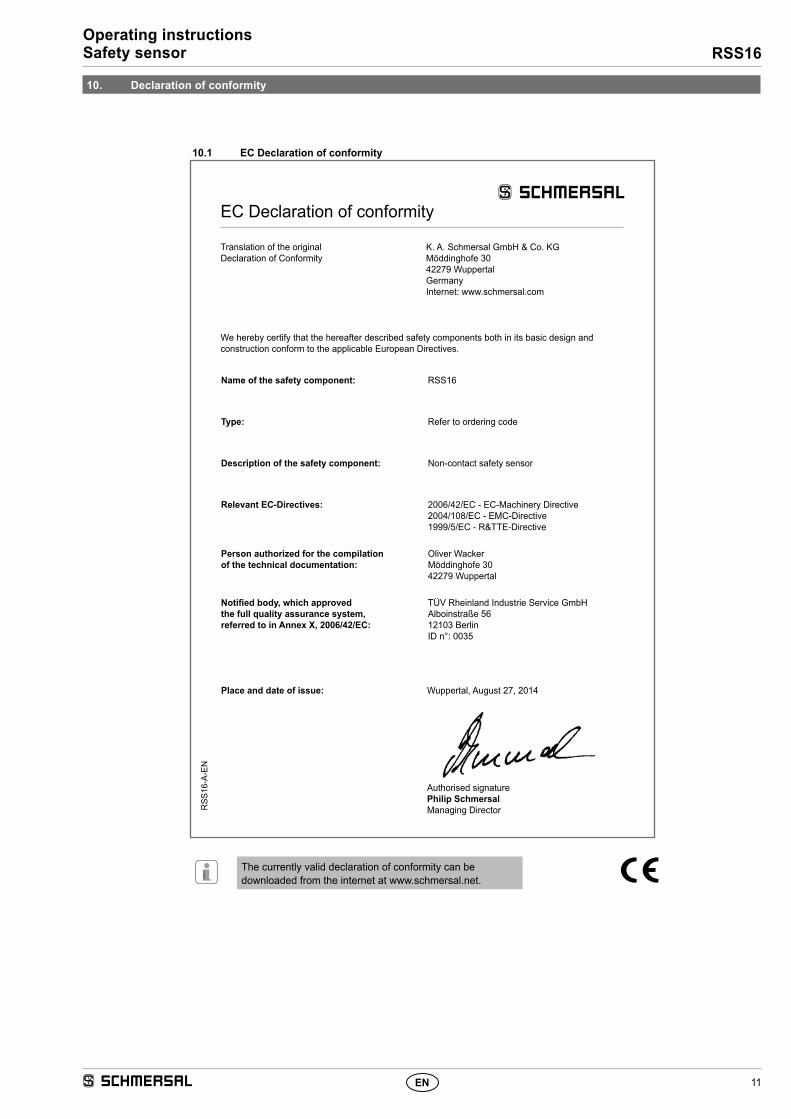
10.1 EC Declaration of conformity
Name of the safety component: RSS16
Type: Refer to ordering code
Description of the safety component: Non-contact safety sensor
Person authorized for the compilation of the technical documentation:
Oliver WackerMöddinghofe 3042279 Wuppertal
Notified body, which approved the full quality assurance system, referred to in Annex X, 2006/42/EC:
TÜV Rheinland Industrie Service GmbHAlboinstraße 5612103 BerlinID n°: 0035
The currently valid declaration of conformity can be downloaded from the internet at www.schmersal.net.
Place and date of issue: Wuppertal, August 27, 2014
Authorised signaturePhilip SchmersalManaging Director
EC Declaration of conformity
Translation of the original Declaration of Conformity
K. A. Schmersal GmbH & Co. KGMöddinghofe 3042279 WuppertalGermanyInternet: www.schmersal.com
We hereby certify that the hereafter described safety components both in its basic design and construction conform to the applicable European Directives.
K. A. Schmersal GmbH & Co. KGMöddinghofe 30, D - 42279 WuppertalPostfach 24 02 63, D - 42232 Wuppertal