142
Answers for industry. SIMOTICS DC Motor Type 1GH7 Operating Instructions / Installation Instructions Edition 11/2013
| Date post: | 23-Apr-2017 |
| Category: |
Documents |
| Upload: | carsamdelt |
| View: | 243 times |
| Download: | 0 times |

Answers for industry.
SIMOTICS DC
Motor
Type 1GH7
Operating Instructions / Installation Instructions
Edition 11/2013

04.11.2013 10:03V2.01

Motor
SIMOTICS DC1GH7
Operating InstructionsInstallation Instructions
Edition 11/2013
Introduction 1
Safety notes 2
Description 3
Preparations for use 4
Assembling 5
Electrical connection 6
Commissioning 7
Operation 8
Maintenance 9
Spare Parts 10
Disposal 11
Service and Support A
Technical data and drawings B
Quality documents C
Checklists D

Legal informationWarning notice system
This manual contains notices you have to observe in order to ensure your personal safety, as well as to prevent damage to property. The notices referring to your personal safety are highlighted in the manual by a safety alert symbol, notices referring only to property damage have no safety alert symbol. These notices shown below are graded according to the degree of danger.
DANGER
indicates that death or severe personal injury will result if proper precautions are not taken.
WARNING
indicates that death or severe personal injury may result if proper precautions are not taken.
CAUTION
indicates that minor personal injury can result if proper precautions are not taken.
NOTICEindicates that property damage can result if proper precautions are not taken.If more than one degree of danger is present, the warning notice representing the highest degree of danger will be used. A notice warning of injury to persons with a safety alert symbol may also include a warning relating to property damage.
Qualified PersonnelThe product/system described in this documentation may be operated only by personnel qualified for the specific task in accordance with the relevant documentation, in particular its warning notices and safety instructions. Qualified personnel are those who, based on their training and experience, are capable of identifying risks and avoiding potential hazards when working with these products/systems.
Proper use of Siemens productsNote the following:
WARNING
Siemens products may only be used for the applications described in the catalog and in the relevant technical documentation. If products and components from other manufacturers are used, these must be recommended or approved by Siemens. Proper transport, storage, installation, assembly, commissioning, operation and maintenance are required to ensure that the products operate safely and without any problems. The permissible ambient conditions must be complied with. The information in the relevant documentation must be observed.
TrademarksAll names identified by ® are registered trademarks of Siemens AG. The remaining trademarks in this publication may be trademarks whose use by third parties for their own purposes could violate the rights of the owner.
Disclaimer of LiabilityWe have reviewed the contents of this publication to ensure consistency with the hardware and software described. Since variance cannot be precluded entirely, we cannot guarantee full consistency. However, the information in this publication is reviewed regularly and any necessary corrections are included in subsequent editions.
Siemens AGIndustry SectorPostfach 48 4890026 NÜRNBERGGERMANY
Order number: A5E02099269A ABⓅ 11/2013 Technical data subject to change
Copyright © Siemens AG 2008, -, 2013.All rights reserved
Table of contents
1 Introduction.................................................................................................................................................11 1.1 About these instructions..............................................................................................................11
2 Safety notes................................................................................................................................................13 2.1 Information for the nominated person in control of the electrical installation..............................13 2.2 The five safety rules:...................................................................................................................13 2.3 Qualified personnel.....................................................................................................................14 2.4 Safe handling..............................................................................................................................14 2.5 Electrostatic sensitive devices.....................................................................................................16 2.6 Electromagnetic compatibility......................................................................................................17 2.7 Interference immunity..................................................................................................................17 2.8 Influence on the line power supply through a strongly irregular torque.......................................17 2.9 Electromagnetic fields when operating electrical power engineering installations......................18
3 Description..................................................................................................................................................19
4 Preparations for use...................................................................................................................................23 4.1 Safety-related aspects to consider when configuring the plant...................................................23 4.2 Noise emissions..........................................................................................................................23 4.3 Ensuring cooling..........................................................................................................................23 4.4 System-inherent frequencies.......................................................................................................24 4.5 Torsional loading of the drive train due to faults in the electrical supply.....................................24 4.6 Transport and storage.................................................................................................................25 4.6.1 Transport markings.....................................................................................................................25 4.6.2 Checking the delivery..................................................................................................................25 4.6.3 Attaching the rotor shipping brace prior to storage.....................................................................25 4.6.4 Checking the load handling attachments....................................................................................26 4.6.5 Requirements for safe lifting and transporting.............................................................................26 4.6.6 Transporting the machine set......................................................................................................27 4.6.7 Lifting and transporting the machine...........................................................................................28 4.6.8 Storage........................................................................................................................................29 4.6.9 Protection against corrosion........................................................................................................32
5 Assembling.................................................................................................................................................33 5.1 Preparations for installation.........................................................................................................33 5.1.1 Requirements for installation.......................................................................................................33 5.1.2 Insulation resistance and polarization index................................................................................34 5.1.3 Testing the insulation resistance and polarization index.............................................................35 5.1.4 Preparing the mating faces.........................................................................................................37 5.1.5 Prepare the mating faces for a flange connection.......................................................................37
SIMOTICS DC 1GH7Operating Instructions 11/2013 5

5.2 Lift the machine to where it will be installed, and position it........................................................37 5.2.1 Preconditions for correct alignment and secure attachment ......................................................37 5.2.2 Checking the load handling attachments....................................................................................38 5.2.3 Removing the rotor shipping brace.............................................................................................38 5.2.4 Removing anti-corrosion protection.............................................................................................39 5.2.5 Mounting the output elements.....................................................................................................40 5.2.6 Lifting and transporting the machine...........................................................................................41 5.2.7 Putting the machine down...........................................................................................................43 5.2.8 Water drain holes........................................................................................................................43 5.2.9 Roughly aligning the machine.....................................................................................................43 5.3 Installing the machine..................................................................................................................44 5.3.1 Safety instructions for installation................................................................................................44 5.3.2 Selecting fixing screws................................................................................................................45 5.3.3 Aligning the machine to the driven machine and attaching it to it (foundation mounting)...........45 5.3.4 Aligning the machine to the driven machine and attaching it to it (flange mounting, vertical)......47 5.3.5 Aligning the machine to the driven machine and mounting (flange, horizontal IM B5)...............47 5.3.6 Mounting the machine.................................................................................................................48 5.3.7 Axial and radial forces.................................................................................................................48
6 Electrical connection...................................................................................................................................51 6.1 Selecting cables..........................................................................................................................51 6.2 Bringing in and routing the cables...............................................................................................51 6.3 Terminal designations.................................................................................................................52 6.4 Connecting cables.......................................................................................................................52 6.5 Connecting the main circuit.........................................................................................................53 6.6 Connecting the grounding conductor..........................................................................................55 6.7 Internal equipotential bonding.....................................................................................................56 6.8 Connecting the auxiliary circuits..................................................................................................56 6.9 Connecting temperature monitoring for the stator winding..........................................................57 6.10 Completing connection work.......................................................................................................58
7 Commissioning...........................................................................................................................................59 7.1 Preparing for commissioning.......................................................................................................59 7.2 Insulation resistance and polarization index................................................................................60 7.3 Greasing the roller bearings prior to commissioning...................................................................61 7.4 Minimum radial forces for cylindrical roller bearings...................................................................61 7.5 Switch on.....................................................................................................................................62 7.6 Overspeed...................................................................................................................................63 7.7 Switch off.....................................................................................................................................63
8 Operation....................................................................................................................................................65 8.1 Switching on the machine...........................................................................................................67 8.2 Regreasing roller bearings..........................................................................................................67
Table of contents
SIMOTICS DC 1GH76 Operating Instructions 11/2013

8.3 Deactivating.................................................................................................................................67 8.4 Switching on again after an emergency switching-off.................................................................67 8.5 Stoppages...................................................................................................................................68 8.5.1 Measures in non-operational periods..........................................................................................68 8.5.2 Avoidance of damage to roller bearings during stoppages.........................................................69 8.5.3 Measurement of the insulation resistance after an extended stoppage......................................69 8.6 Decommissioning the machine...................................................................................................70 8.7 Re-commissioning the machine..................................................................................................70 8.8 Special operating conditions.......................................................................................................70 8.9 Faults ..........................................................................................................................................71 8.9.1 Inspections in the event of faults.................................................................................................71 8.9.2 Faults in operation.......................................................................................................................72 8.9.3 Roller bearing faults....................................................................................................................73 8.9.4 Brush faults.................................................................................................................................74 8.9.5 Commutator faults.......................................................................................................................75
9 Maintenance...............................................................................................................................................77 9.1 Inspection and maintenance.......................................................................................................77 9.1.1 Initial inspection...........................................................................................................................78 9.1.2 MTTR..........................................................................................................................................80 9.1.3 Main inspection...........................................................................................................................80 9.1.4 Regreasing rolling-contact bearings............................................................................................81 9.1.5 Regreasing intervals and grease types.......................................................................................82 9.1.6 Clean the machine......................................................................................................................83 9.1.7 Checking the carbon brushes......................................................................................................84 9.1.8 Replacing the carbon brushes.....................................................................................................85 9.1.9 Setting the brush rocker and brush holder..................................................................................86 9.1.10 Maintaining the commutator........................................................................................................86 9.1.11 Maintaining terminal boxes..........................................................................................................88 9.1.12 Touch up any damaged paintwork..............................................................................................89 9.2 Repair..........................................................................................................................................89 9.2.1 Prepare servicing work................................................................................................................90 9.2.2 Disassembling the machine........................................................................................................91 9.2.3 Removing rolling-contact bearings..............................................................................................92 9.2.4 Installing the machine..................................................................................................................92 9.2.5 Mounting the rolling-contact bearings.........................................................................................93 9.2.6 Replacing the speed encoder......................................................................................................94 9.2.6.1 Speed sensor with conical hub....................................................................................................94 9.2.6.2 Speed sensor for overhung mounting.........................................................................................96 9.2.6.3 Speed sensor for construction type IM B5..................................................................................97
10 Spare Parts...............................................................................................................................................101 10.1 Ordering data............................................................................................................................101 10.2 Ordering spare parts via the Internet.........................................................................................102 10.3 Using commercially available spare parts.................................................................................102 10.4 Stator and rotor.........................................................................................................................103
Table of contents
SIMOTICS DC 1GH7Operating Instructions 11/2013 7

10.5 Rolling-contact bearing..............................................................................................................104 10.5.1 Rolling-contact bearing for 1G.7, 1H.7, shaft heights 355 to 450, drive end.............................104 10.5.2 Rolling-contact bearing for 1G.7, 1H.7, shaft heights 355 to 450 with one shaft extension,
non-drive end............................................................................................................................106 10.5.3 Rolling-contact bearing for 1G.7, 1H.7, shaft heights 355 to 450 with two shaft extensions,
non-drive end............................................................................................................................107 10.5.4 Rolling-contact bearing seal 1G.6, 1H.6, 1G.7, 1H.7................................................................108 10.6 Terminal boxes..........................................................................................................................109 10.6.1 1XB7720 main terminal box......................................................................................................109 10.6.2 Auxiliary terminal box................................................................................................................110 10.7 Speed sensor............................................................................................................................111 10.7.1 Shaft heights 180 to 630...........................................................................................................111 10.7.1.1 Speed sensor with conical hub..................................................................................................111 10.7.1.2 Speed sensor for overhung mounting.......................................................................................112 10.7.1.3 Speed sensor for construction type IM B5................................................................................113
11 Disposal....................................................................................................................................................115 11.1 Introduction................................................................................................................................115 11.2 National statutory regulations....................................................................................................115 11.3 Dismantling the machine...........................................................................................................115 11.4 Disposal of components............................................................................................................115
A Service and Support.................................................................................................................................117 A.1 Siemens Industry Online Support..............................................................................................117 A.2 Reduction of hazardous substances.........................................................................................118
B Technical data and drawings....................................................................................................................119 B.1 Tightening torques for screw and bolt connections...................................................................119
C Quality documents....................................................................................................................................121 C.1 EC Declaration of Conformity 2006/95/EC................................................................................121
D Checklists.................................................................................................................................................131 D.1 Switching on..............................................................................................................................132 D.2 Commissioning..........................................................................................................................133 D.3 Inspection at standstill...............................................................................................................134 D.4 Inspection when the motor is running........................................................................................135
Index.........................................................................................................................................................137
Tables
Table 3-1 Insulation classes of series 1G... and 1H....................................................................................20Table 3-2 Machine design ..........................................................................................................................21Table 3-3 Data on the rating plate..............................................................................................................21Table 4-1 Tightening torques for the shaft screw on the rotor shipping brace............................................28
Table of contents
SIMOTICS DC 1GH78 Operating Instructions 11/2013

Table 5-1 Stator winding insulation resistance at 40° C..............................................................................36Table 5-2 Permissible deviations for aligning the machine with flexible coupling.......................................46Table 6-1 Terminal designations in example B1.........................................................................................52Table 6-2 Terminal box connection data.....................................................................................................53Table 6-3 Tightening torque of screws with cable lugs................................................................................55Table 6-4 Tightening torque of screws with ground terminals.....................................................................56Table 7-1 Minimum radial forces.................................................................................................................62Table 8-1 Vibration magnitude as a function of vibration frequency............................................................67Table 8-2 Faults in operation.......................................................................................................................72Table 8-3 Roller bearing faults ...............................................................................................................73Table 8-4 Brush faults.................................................................................................................................74Table 8-5 Commutator faults.......................................................................................................................75Table 9-1 MTTR in fault-free operation ......................................................................................................80Table 9-2 Suitable greases for rolling-contact bearings (down to -20 °C)...................................................82Table 9-3 Commutator overhaul – minimum permissible diameter.............................................................87Table 9-4 Recommended torques for tightening the shaft journal...............................................................94Table 9-5 Recommended torques for tightening the shaft journal...............................................................96Table 9-6 Recommended torques for tightening the half-coupling..............................................................98Table 9-7 Tightening torques for joining coupling........................................................................................99Table 10-1 Spare parts stator and rotor 1G.7, 1H.7, shaft heights 355 to 450...........................................103Table 10-2 Spare parts rolling-contact bearing for 1H.7, 1G.7....................................................................104Table 10-3 Spare parts rolling-contact bearing for 1G.7. 1H.7 with one shaft extension............................106Table 10-4 Spare parts rolling-contact bearing for 1G.7. 1H.7 with two shaft extensions...........................107Table 10-5 Spare parts sealing for rolling-contact bearing for 1H.6, 1G.6..................................................108Table 10-6 Spare parts terminal box 1XB7720...........................................................................................109Table 10-7 Spare parts auxiliary terminal box.............................................................................................110Table 10-8 Spare parts speed sensor with conical hub for shaft heights 180 to 630..................................111Table 10-9 Spare parts speed sensor for overhung mounting for shaft heights 180 to 630.......................112Table 10-10 Spare parts speed sensor for construction type IM B5 for shaft heights 180 to 630.................113Table B-1 Tightening torques for bolted connections with a tolerance of ±10%........................................119Table D-1 Items to check during switch-on................................................................................................132Table D-2 Items to check during commissioning.......................................................................................133Table D-3 Items to inspect when machine is at standstill..........................................................................134Table D-4 Items to inspect when the motor is running...............................................................................135
Figures
Figure 3-1 Block diagram of motor type 1GH...............................................................................................19Figure 3-2 Schematic rating plate.................................................................................................................21
Table of contents
SIMOTICS DC 1GH7Operating Instructions 11/2013 9
Figure 4-1 Rotor shipping brace without coupling (1) and with coupling (2). ...............................................28Figure 5-1 Balancing type on the drive-end side..........................................................................................40Figure 5-2 Schematic diagram: Aligning the machine to the driven machine...............................................46Figure 6-1 Connection of main terminals with cable lug...............................................................................54Figure 6-2 Connection of auxiliary terminals with cable lug..........................................................................54Figure 6-3 Connection without cable lugs.....................................................................................................54Figure 9-1 Adjusting the brush rocker: fixed part (1), brush rocker (2).........................................................86Figure 9-2 Reworking the slots.....................................................................................................................88Figure 9-3 Final work on the commutator after skimming.............................................................................88Figure 9-4 Speed sensor assembly .............................................................................................................95Figure 9-5 Speed sensor assembly .............................................................................................................97Figure 9-6 Speed sensor assembly..............................................................................................................99Figure 10-1 Side view stator and rotor 1G.7, 1H.7.......................................................................................103Figure 10-2 Rolling-contact bearing for 1H.7, 1G.7......................................................................................104Figure 10-3 Rolling-contact bearing for 1G.7. 1H.7 with one shaft extension..............................................106Figure 10-4 Rolling-contact bearing for 1G.7. 1H.7 with two shaft extensions.............................................107Figure 10-5 Sealing for rolling-contact bearing for 1H.6, 1G.6.....................................................................108Figure 10-6 Main terminal box 1XB7720 .....................................................................................................109Figure 10-7 Cable entry plate 1XB7720.......................................................................................................109Figure 10-8 Auxiliary terminal box................................................................................................................110Figure 10-9 Speed sensor with conical hub for shaft heights 180 to 630.....................................................111Figure 10-10 Speed sensor for overhung mounting for shaft heights 180 to 630..........................................112Figure 10-11 Speed sensor for construction type IM B5 for shaft heights 180 to 630....................................113
Table of contents
SIMOTICS DC 1GH710 Operating Instructions 11/2013

Introduction 11.1 About these instructions
These instructions describe the machine and explain how to handle it, from initial delivery to final disposal of the equipment. Keep these instructions for later use.
Read these operating instructions before you handle the machine and follow the instructions. to become familiar with its design and operating principles and thus ensure safe, problem-free machine operation and long service life.
If you have suggestions for improving the document, please contact our Service Center.
Text format featuresThe warning notice system is explained on the rear of the inside front. Always follow the safety instructions and notices in these instructions.
In addition to the safety-related warning notices which you must read, you will find the text in these instructions is formatted in the following way:
1. Handling instructions are always formatted as a numbered list. Always perform the steps in the order given.
● Lists are formatted as bulleted lists.
– Lists on the second level are hyphenated.
Note
A Note is an important item of information about the product, handling of the product or the relevant section of the document. Notes provide you with help or further suggestions/ideas.
SIMOTICS DC 1GH7Operating Instructions 11/2013 11

Introduction1.1 About these instructions
SIMOTICS DC 1GH712 Operating Instructions 11/2013

Safety notes 22.1 Information for the nominated person in control of the electrical
installationThis electric machine has been designed and built in accordance with the specifications contained in Directive 2006/95/EC ("Low-Voltage Directive") and is intended for use in industrial plants. Please observe the country-specific regulations when using the electric machine outside the European Community. Follow the local and industry-specific safety and setup regulations.
The persons responsible for the plant must ensure the following:
● Planning and configuration work and all work carried out on and with the machine is only to be done by qualified personnel.
● The operating instructions must always be available for all work.
● The technical data as well as the specifications relating to the permissible installation, connection, ambient and operating conditions are taken into account at all times.
● The specific setup and safety regulations as well as regulations on the use of personal protective equipment are observed.
Note
Use the services and support provided by the appropriate Service Center (Page 117) for planning, installation, commissioning, and servicing work.
You will find safety instructions in the individual sections of this document. Follow the safety instructions for your own safety, to protect other people and to avoid damage to property.
Observe the following safety instructions for all activities on and with the machine.
2.2 The five safety rules:For your personal safety and to prevent material damage when carrying out any work, always observe the safety instructions and the following five safety rules, according to EN 50110‑1 "Working in a voltage-free state". Apply the five safety rules in the sequence stated before starting work.
Five safety rules 1. Disconnect the system.
Disconnect the auxiliary circuits, for example anti-condensation heating.
2. Protect against reconnection.
3. Make sure that the equipment is de-energized (in a no-voltage condition).
SIMOTICS DC 1GH7Operating Instructions 11/2013 13
4. Ground and short-circuit.
5. Cover or provide barriers around adjacent components that are still live.
To energize the system, apply the measures in reverse order.
2.3 Qualified personnelAll work at the machine must be carried out by qualified personnel only. For the purpose of this documentation, qualified personnel is taken to mean people who fulfill the following requirements:
● Through appropriate training and experience, they are able to recognize and avoid risks and potential dangers in their particular field of activity.
● They have been instructed to carry out work on the machine by the appropriate person responsible.
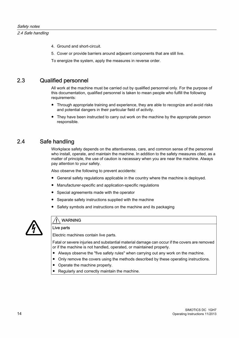
2.4 Safe handlingWorkplace safety depends on the attentiveness, care, and common sense of the personnel who install, operate, and maintain the machine. In addition to the safety measures cited, as a matter of principle, the use of caution is necessary when you are near the machine. Always pay attention to your safety.
Also observe the following to prevent accidents:
● General safety regulations applicable in the country where the machine is deployed.
● Manufacturer-specific and application-specific regulations
● Special agreements made with the operator
● Separate safety instructions supplied with the machine
● Safety symbols and instructions on the machine and its packaging
WARNING
Live parts
Electric machines contain live parts.
Fatal or severe injuries and substantial material damage can occur if the covers are removed or if the machine is not handled, operated, or maintained properly.● Always observe the "five safety rules" when carrying out any work on the machine.● Only remove the covers using the methods described by these operating instructions.● Operate the machine properly.● Regularly and correctly maintain the machine.
Safety notes2.4 Safe handling
SIMOTICS DC 1GH714 Operating Instructions 11/2013

WARNING
Rotating components
Electric machines contain dangerous rotating parts.
Fatal or severe injuries and substantial material damage can occur if the covers are removed or if the machine is not handled, operated, or maintained properly.● Only remove the covers using the methods described by these operating instructions.● Operate the machine properly.● Perform regular maintenance on the machine.● Secure free-standing shaft ends.
WARNING
Hot surfaces
Electric machines have hot surfaces. Do not touch these surfaces. They could cause burns.● Allow the machine to cool before starting work on the machine.● Only remove the covers using the methods described by these operating instructions.● Operate the machine properly.
CAUTION
Hazardous substances
Chemical substances required for the setup, operation and maintenance of machines can present a health risk.
Poisoning, skin damage, cauterization of the respiratory tract, and other health damage may result.● Read the information in these operating instructions and the product information supplied
by the manufacturer.● Observe the relevant safety regulations and wear the personal protective equipment
specified.
CAUTION
Flammable substances
Chemical substances required for the setup, operation and maintenance of machines may be flammable.
Burns and other damage to health and material may result.● Read the information in these operating instructions and the product information supplied
by the manufacturer.● Observe the relevant safety regulations and wear the personal protective equipment
specified.
Safety notes2.4 Safe handling
SIMOTICS DC 1GH7Operating Instructions 11/2013 15
WARNING
Noise emissions
During operation, the machine's noise emission levels can exceed those permitted at the work place. which can cause hearing damage.
Take steps to reduce noise, such as introducing covers and protective insulation or adopting hearing protection measures, so that the machine can be operated safely within your system.
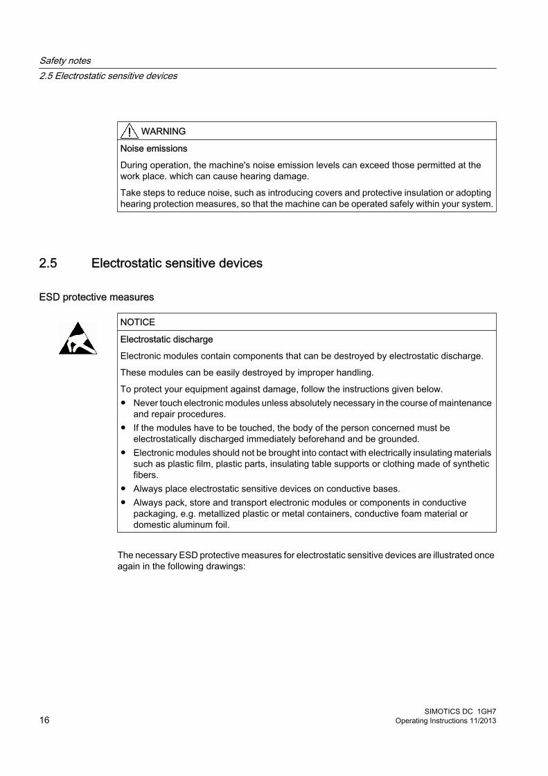
2.5 Electrostatic sensitive devices
ESD protective measures
NOTICE
Electrostatic discharge
Electronic modules contain components that can be destroyed by electrostatic discharge.
These modules can be easily destroyed by improper handling.
To protect your equipment against damage, follow the instructions given below.● Never touch electronic modules unless absolutely necessary in the course of maintenance
and repair procedures. ● If the modules have to be touched, the body of the person concerned must be
electrostatically discharged immediately beforehand and be grounded.● Electronic modules should not be brought into contact with electrically insulating materials
such as plastic film, plastic parts, insulating table supports or clothing made of synthetic fibers.
● Always place electrostatic sensitive devices on conductive bases.● Always pack, store and transport electronic modules or components in conductive
packaging, e.g. metallized plastic or metal containers, conductive foam material or domestic aluminum foil.
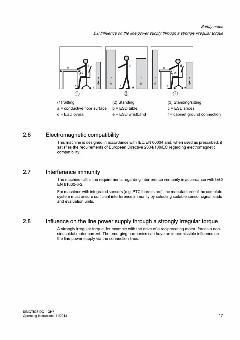
The necessary ESD protective measures for electrostatic sensitive devices are illustrated once again in the following drawings:
Safety notes2.5 Electrostatic sensitive devices
SIMOTICS DC 1GH716 Operating Instructions 11/2013
d
f f f f
b
e
a a ac c c
e
b
f
d d
e
a
(1) Sitting (2) Standing (3) Standing/sittinga = conductive floor surface b = ESD table c = ESD shoesd = ESD overall e = ESD wristband f = cabinet ground connection
2.6 Electromagnetic compatibilityThis machine is designed in accordance with IEC/EN 60034 and, when used as prescribed, it satisfies the requirements of European Directive 2004/108/EC regarding electromagnetic compatibility.
2.7 Interference immunityThe machine fulfills the requirements regarding interference immunity in accordance with IEC/EN 61000‑6‑2.
For machines with integrated sensors (e.g. PTC thermistors), the manufacturer of the complete system must ensure sufficient interference immunity by selecting suitable sensor signal leads and evaluation units.
2.8 Influence on the line power supply through a strongly irregular torqueA strongly irregular torque, for example with the drive of a reciprocating motor, forces a non-sinusoidal motor current. The emerging harmonics can have an impermissible influence on the line power supply via the connection lines.
Safety notes2.8 Influence on the line power supply through a strongly irregular torque
SIMOTICS DC 1GH7Operating Instructions 11/2013 17

2.9 Electromagnetic fields when operating electrical power engineering installations
WARNING
Interference to electronic devices caused by electrical power equipment
Electrical power equipment generate electric fields during operation. Potentially lethal malfunctions can occur in medical implants, e.g. pacemakers, in the vicinity of electrical power equipment. Data may be lost on magnetic or electronic data carriers.● It is forbidden for people with pacemakers to enter the vicinity of the machine. ● Protect the personnel working in the plant by taking appropriate measures, such as
erecting identifying markings, safety barriers and warning signs and giving safety talks.● Observe the nationally applicable health and safety regulations.● Do not carry any magnetic or electronic data media.
Safety notes2.9 Electromagnetic fields when operating electrical power engineering installations
SIMOTICS DC 1GH718 Operating Instructions 11/2013
Description 3
ApplicationsDC machine of the 1GH7... series are implemented with open-circuit or closed-circuit cooling with a laminated stator yoke.
They are designed for a wide range of drive and energy conversion applications and comply with the harmonized standards of series IEC / EN 60034 (VDE 0530).
WARNING
Risk of explosion
This machine is not designed for use in hazardous areas. An explosion can occur if the machine is operated in these areas. This can result in death, serious injury or material damage.
Never operate this machine in hazardous areas.
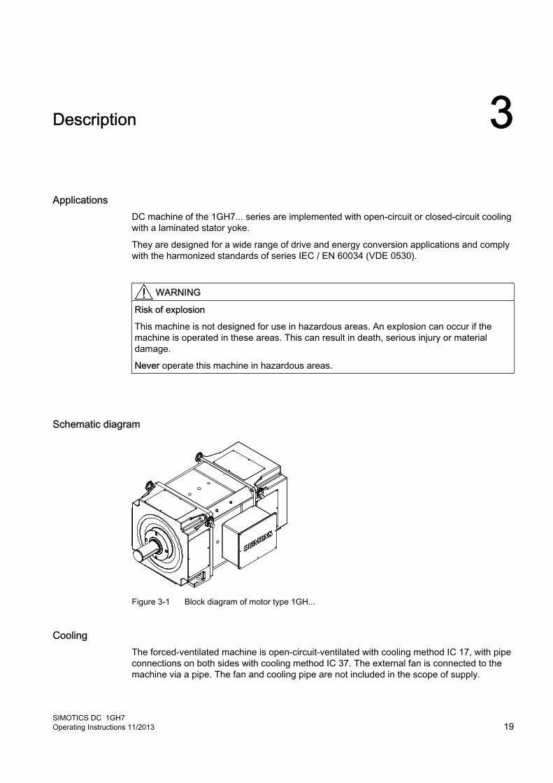
Schematic diagram
Figure 3-1 Block diagram of motor type 1GH...
CoolingThe forced-ventilated machine is open-circuit-ventilated with cooling method IC 17, with pipe connections on both sides with cooling method IC 37. The external fan is connected to the machine via a pipe. The fan and cooling pipe are not included in the scope of supply.
SIMOTICS DC 1GH7Operating Instructions 11/2013 19
DesignThe machine has no housing, but is designed with a fully laminated stator yoke which allows a rate of current change of up to 250 IN/sec.
Insulation systemThe high-quality DURIGNIT® 2000 insulation system means that the motors are suitable for use in both tropical humidity and industrial environments. You will find the insulation classes in the following table.
Table 3-1 Insulation classes of series 1G... and 1H...
Series Insulation class1GG5
155 (F)1GH51HS51HQ51GG6, 1GG7
180 (H)1GH6, 1GH71HS6, 1HS71HQ6, 1HQ7
Degree of protectionWith a pipe connection on one side, the machine has degree of protection IP23; with pipe connections on both sides, it has degree of protection IP54.
Ambient conditionsUnless otherwise specified, the rated powers apply for continuous operation at a coolant temperature of ≤ 40 °C and an installation altitude of up to 1000 m above sea level. Please note any data to the contrary on the rating plate. Operating conditions must comply with the specifications on the rating plate.
Machine design You will find regulations and standards for rating and testing this motor on the rating plate. The machine design basically complies with the following standards. Refer to the EC Declaration of Conformity for the versions of the harmonized standards referenced.
Description
SIMOTICS DC 1GH720 Operating Instructions 11/2013
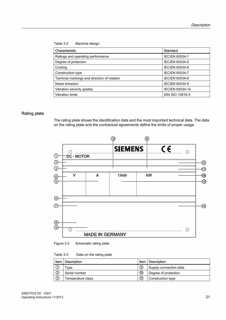
Table 3-2 Machine design
Characteristic StandardRatings and operating performance IEC/EN 60034‑1Degree of protection IEC/EN 60034‑5Cooling IEC/EN 60034‑6Construction type IEC/EN 60034‑7Terminal markings and direction of rotation IEC/EN 60034‑8Noise emission IEC/EN 60034‑9Vibration severity grades IEC/EN 60034‑14Vibration limits DIN ISO 10816-3
Rating plateThe rating plate shows the identification data and the most important technical data. The data on the rating plate and the contractual agreements define the limits of proper usage.
1
2
3
4
5
6
7
8
9
10 11
12
13
14
15
16
Figure 3-2 Schematic rating plate
Table 3-3 Data on the rating plate
Item Description Item Description① Type ⑨ Supply connection data② Serial number ⑩ Degree of protection③ Temperature class ⑪ Construction type
Description
SIMOTICS DC 1GH7Operating Instructions 11/2013 21
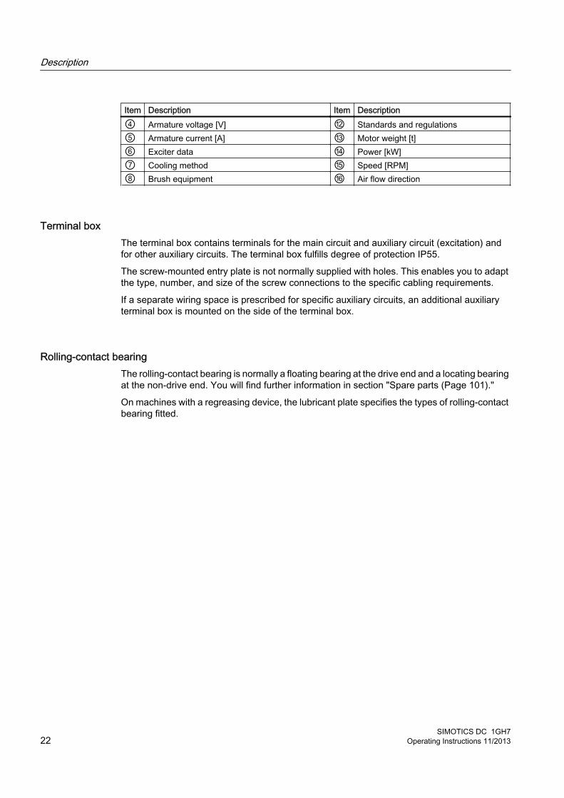
Item Description Item Description④ Armature voltage [V] ⑫ Standards and regulations⑤ Armature current [A] ⑬ Motor weight [t]⑥ Exciter data ⑭ Power [kW]⑦ Cooling method ⑮ Speed [RPM]⑧ Brush equipment ⑯ Air flow direction
Terminal boxThe terminal box contains terminals for the main circuit and auxiliary circuit (excitation) and for other auxiliary circuits. The terminal box fulfills degree of protection IP55.
The screw-mounted entry plate is not normally supplied with holes. This enables you to adapt the type, number, and size of the screw connections to the specific cabling requirements.
If a separate wiring space is prescribed for specific auxiliary circuits, an additional auxiliary terminal box is mounted on the side of the terminal box.
Rolling-contact bearingThe rolling-contact bearing is normally a floating bearing at the drive end and a locating bearing at the non-drive end. You will find further information in section "Spare parts (Page 101)."
On machines with a regreasing device, the lubricant plate specifies the types of rolling-contact bearing fitted.
Description
SIMOTICS DC 1GH722 Operating Instructions 11/2013

Preparations for use 4
Good planning and preparation of machine applications are essential in terms of keeping installation simple and avoiding errors, ensuring safe operation, and allowing access to the machine for servicing and corrective maintenance.
This chapter outlines what you need to consider when configuring your plant in relation to this machine and the preparations you need to make before the machine is delivered.
4.1 Safety-related aspects to consider when configuring the plantA number of residual risks are associated with the machine. These are described in the chapter titled "Safety information" and in related sections.
Take appropriate safety precautions (covers, barriers, markings, etc.) to ensure the machine is operated safely within your plant.
Observing the operating mode Observe the machine's operating mode. Use a suitable control system to prevent overspeeds, thus protecting the machine from damage.
4.2 Noise emissions
WARNING
Noise emissions
During operation, the machine's noise emission levels can exceed those permitted at the work place. which can cause hearing damage.
Take steps to reduce noise, such as introducing covers and protective insulation or adopting hearing protection measures, so that the machine can be operated safely within your system.
4.3 Ensuring coolingEnsure that the machine is sufficiently cooled by the cooling air flow at the installation site:
SIMOTICS DC 1GH7Operating Instructions 11/2013 23
● The cooling air can flow in and out freely.The full air flow provided by the fan is only achieved if air can freely enter the impeller. A clearance of at least 1 times the air intake diameter must therefore be provided in the axial direction.
● Hot discharged air must not be drawn in again.
● If there is no protective canopy, then for vertical types of construction where the air enters from the top, the air entry openings must be protected against the ingress of foreign bodies and water.
4.4 System-inherent frequencies
NOTICE
Machine damage caused by system resonances
The system consisting of the foundation and machine set must be configured and matched in such a way that no system resonances can arise and result in the permissible vibration levels being exceeded. Excessive vibrations can damage the machine set.
DIN 4024 must be taken into account when constructing the machine foundation. The limit values in accordance with DIN ISO 10816-3 must not be exceeded.
4.5 Torsional loading of the drive train due to faults in the electrical supplyIn the event of faults in the electrical supply, such as failure of the field supply or short circuit across terminals, excessive air gap torques can occur, which can lead to additional torsional loads on the drive train.
WARNING
Serious damage to the machine
If the configuration does not correctly recognize the mechanical torsional loadings of the shaft assembly, this can lead to serious damage to the machine. This can result in death, serious injury or material damage.
When planning the system, make due allowance for the maximum air gap torques that can occur.
Note
The system planner is responsible for the entire drive train.
Preparations for use4.5 Torsional loading of the drive train due to faults in the electrical supply
SIMOTICS DC 1GH724 Operating Instructions 11/2013
4.6 Transport and storage
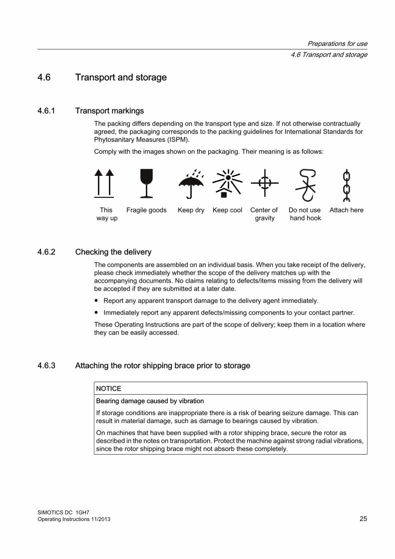
4.6.1 Transport markingsThe packing differs depending on the transport type and size. If not otherwise contractually agreed, the packaging corresponds to the packing guidelines for International Standards for Phytosanitary Measures (ISPM).
Comply with the images shown on the packaging. Their meaning is as follows:
This way up
Fragile goods Keep dry Keep cool Center of gravity
Do not use hand hook
Attach here
4.6.2 Checking the deliveryThe components are assembled on an individual basis. When you take receipt of the delivery, please check immediately whether the scope of the delivery matches up with the accompanying documents. No claims relating to defects/items missing from the delivery will be accepted if they are submitted at a later date.
● Report any apparent transport damage to the delivery agent immediately.
● Immediately report any apparent defects/missing components to your contact partner.
These Operating Instructions are part of the scope of delivery; keep them in a location where they can be easily accessed.
4.6.3 Attaching the rotor shipping brace prior to storage
NOTICE
Bearing damage caused by vibration
If storage conditions are inappropriate there is a risk of bearing seizure damage. This can result in material damage, such as damage to bearings caused by vibration.
On machines that have been supplied with a rotor shipping brace, secure the rotor as described in the notes on transportation. Protect the machine against strong radial vibrations, since the rotor shipping brace might not absorb these completely.
Preparations for use4.6 Transport and storage
SIMOTICS DC 1GH7Operating Instructions 11/2013 25

NOTICE
Bearing damage
If the customer has already mounted parts, for example coupling, belt pulley, etc., the bearing can be damaged during transport.
In this case, make sure that the customer uses a rotor shipping brace. If the rotor shipping brace is not attached, regularly turn the rotor.
4.6.4 Checking the load handling attachmentsInspect the load handling attachments such as the load stands, lifting eyes and ring bolts and also the lifting gear, before lifting the machine:
● Inspect the load handling attachments on the machine for possible damage. Replace any load handling attachments that are found to be damaged.
● Check before use that the load handling attachments are correctly secured.
● When lifting the machine, use only approved and undamaged lifting gear of sufficient rated capacity. Check these before using them.
WARNING
The machine can be dropped
If the load handling attachments and lifting gear are damaged or not correctly secured, the machine may be dropped during lifting. This can result in death, serious injury or material damage. Inspect the load handling attachments and lifting gear before use.
4.6.5 Requirements for safe lifting and transportingTo safely lift and transport the machine, the following requirements must be met:
● Personnel operating cranes and fork-lift trucks must be appropriately qualified.
● When lifting the machine, use only approved and undamaged sling guides and spreaders of sufficient rated capacity. Check the lifting equipment prior to its use. The weight of the machine is shown on the rating plate.
● When lifting the machine, refer to the information on the lifting plate.
– Comply with the specified spreading angles.
– Do not exceed the maximum lifting acceleration and lifting speed specified on the lifting plate. Lift the machine without jerking it.Acceleration a ≤ 3.942 m/s2 Velocity v ≤ 20 m/min
● Use only the load carrying device on the stator frame for lifting.
Preparations for use4.6 Transport and storage
SIMOTICS DC 1GH726 Operating Instructions 11/2013
WARNING
The machine can tip, move or fall down
If you do not transport or lift the machine in a position appropriate for its construction, the machine can tip, slip into the lifting equipment or fall down. This can result in death, serious injury or material damage.● Use only the load carrying device on the stator frame for lifting.● Use the load carrying device appropriate for the machine position. ● Use suitable rope guiding or spreading devices. The weight of the machine is shown on
the rating plate.
WARNING
The machine can tip, move or fall down
If the center of gravity of a load is not located centrally between the attachment points, the motor can tip over or slip out of the lifting equipment and fall when it is being transported or lifted. This can result in death, serious injury or material damage.● Comply with the handling instructions on the machine when transporting it.● Be aware of the possibility of different loads on the sling ropes or lifting straps and the
carrying capacity of the lifting equipment.● Always take account of the center of gravity when transporting or lifting the motor. If the
center of gravity is not located centrally between the attachment points, then position the hoisting hook above the center of gravity.
4.6.6 Transporting the machine set
WARNING
Falling down of the machine
The lifting lugs on the machine are designed only for the weight of the machine. If a machine set is lifted and transported on a single machine, this can lead to mechanical failure of the lifting lug. The machine or machine set may fall. This can result in death, serious injury or material damage.● Do not lift machine sets by attaching lifting tackle to the individual machines.● Use only the equipment provided, e.g. the openings or lugs on the base plates, for
transporting machine sets. Note the maximum capacity of the lifting lug.
Preparations for use4.6 Transport and storage
SIMOTICS DC 1GH7Operating Instructions 11/2013 27
4.6.7 Lifting and transporting the machine
NOTICE
Transport damage if the rotor shipping brace is not used.
The motor can be damaged if it is jolted during transport.
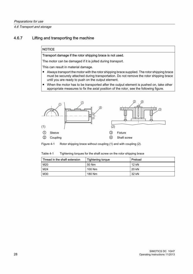
This can result in material damage.● Always transport the motor with the rotor shipping brace supplied. The rotor shipping brace
must be securely attached during transportation. Do not remove the rotor shipping brace until you are ready to push on the output element.
● When the motor has to be transported after the output element is pushed on, take other appropriate measures to fix the axial position of the rotor, see the following figure.
① Sleeve ③ Fixture② Coupling ④ Shaft screw
Figure 4-1 Rotor shipping brace without coupling (1) and with coupling (2).
Table 4-1 Tightening torques for the shaft screw on the rotor shipping brace
Thread in the shaft extension Tightening torque PreloadM20 50 Nm 12 kNM24 100 Nm 20 kNM30 180 Nm 32 kN
Preparations for use4.6 Transport and storage
SIMOTICS DC 1GH728 Operating Instructions 11/2013

WARNING
Transporting or lifting the machine
The motor or the motor set may only be transported and lifted with the hoisting lugs, as it might otherwise tip over or slip out of the lifting equipment. Death, serious injury, or material damage can result.● Always use the lugs on the stator frame to lift the motor. Use suitable rope guidance or
spreading devices. You will find the weight of the motor on the rating plate. ● Only lift and transport the motors in a position appropriate to their design.● Vertical-design motors must always be transported in the vertical position if the rotor is
not fixed. If transport in a horizontal position should prove to be necessary in special cases, then fix the rotor before bringing the motor the horizontal position. If necessary, vertical motors with suitable bearings are supplied by the manufacturing plant in the horizontal position.
NotePlace the machine in a secure and raised position
In order to obtain easy and safe access to the underside of the machine, place it in a secure and raised position.
DANGER
Standing under suspended loads
If the lifting gear or load handling attachments were to fail, the machine could fall. This can result in death, serious injury or material damage.
Never remain under or in the immediate vicinity of the machine when it is raised.
4.6.8 StorageIf the machine is not going to be commissioned soon after delivery, ensure that it is stored correctly.
NOTICE
Seizure damage to bearings
If the machine is stored incorrectly there is a risk that the bearings will suffer damage while out of use. Examples of resulting damage can include scoring and corrosion.
Read the following storage instructions.
Preparations for use4.6 Transport and storage
SIMOTICS DC 1GH7Operating Instructions 11/2013 29
Preconditions and preparations● Only store goods in undamaged packaging. If goods are delivered in damaged packaging,
unpack them and store appropriately according to the nature of the goods.
● Repair any damage to the packaging before putting the equipment into storage insofar as this is necessary to ensure proper storage conditions.
General instructions for storageWherever possible, store the machine in a storage room. The place of storage must satisfy the following general conditions:
● Select a sufficiently sized dry and horizontal place of storage that is above flood level and free of vibration (veff ≤ 0.2 mm/s).
– The place of storage must be well ventilated as well as free of dust and frost. Provide protection against extreme weather conditions. Ensure that the temperature remains stable in the range from 10° C (50° F) to 50° C (120° F). The room temperature should be approx. 10 K above the outside temperature. The temperature should not fall below ‑20° C.
– The relative humidity of the air should be less than 60%.
– The floor of the place of storage must be sufficiently strong. The maximum permissible floor loading or storage compartment loading may not be exceeded.
– The ambient air must not contain any harmful gases.
● Protect the motor from shocks and humidity.
● Position machines, devices and crates on pallets, wooden beams or foundations that protect them against rising damp and water.
● Ensure that the air circulation under the equipment is not impeded.
– Place wooden spacer blocks between the covers and the motor.
– Covers or tarpaulins must not trail on the floor around the machine.
Storing outdoors For outdoor storage, the following additional conditions must be satisfied:
● The ground must be sufficiently strong. Prevent the motor from sinking into the ground.
● Covers or tarpaulins used to protect the equipment against the weather must not make contact with the surfaces of the equipment. Otherwise air circulation under the stored items will be prevented.
Preparations for use4.6 Transport and storage
SIMOTICS DC 1GH730 Operating Instructions 11/2013

Protection against humidity If a dry storage space is not available, protect the machine as follows against humidity:
● Wrap the machine in humidity-absorbent material.
● Wrap the machine in plastic film:
– Place a humidity meter inside the plastic film.
– Place desiccant within the plastic film.
– Pack the machine air-tight.
● Inspect the machine regularly.
If you do not intend to commission the machine immediately, take the following precautions:
● Always keep the terminal box's cover tightly sealed.
● Do not remove the rotor shipping brace device supplied.
● Open the pressure fingers of the brush holders. Take the brushes out of the holders.
● If necessary, reapply the anti-corrosion protection at the shaft extension.
Long-term storage If you are storing a machine for more than six months, you must check its condition every six months. Store the machine in accordance with the specifications in Section "Storage", and if possible, packed.
● Check the motor for damage.
● Carry out any necessary maintenance work.
● Make sure that the storage conditions are such that condensation cannot form in the motor.
● If the machine is not sealed in plastic film, continually and slightly heat the machine, e.g. with anti-condensation heating (if available), and ensure that the air circulates in the storage room.
Storage for longer than two yearsLubricate the machine after every two years of storage.
1. Unpack the machine.
2. Remove the rotor shipping brace, if one is being used.
Preparations for use4.6 Transport and storage
SIMOTICS DC 1GH7Operating Instructions 11/2013 31

3. While the rotor is rotating, lubricate with twice the grease quantity in accordance with the lubricant plate. This ensures that the grease is evenly distributed and covers all surfaces. Corrosion damage is avoided.
NOTICE
Damage to roller bearings
Roller bearings can be damaged when kept in the same or almost the same position.
Make sure that the resting position of the roller bearings after the rotor has been turned is different from what it previously had been. Use the feather key as a reference point, if present.
4. Replace the corrosion protection.
5. Reattach the rotor shipping brace, if present.
6. Pack the machine again.
4.6.9 Protection against corrosionIf the machine is stored in dry conditions, then apply the subsequently listed anti-corrosion measures:
● Storage up to six months:Apply a coat of corrosion protective compound to all accessible bare metal parts such as the exposed shaft extension, flange or machine feet.
● Storage for longer than six months:Apply a coat of anti-corrosion compound which provides long-term protection, e.g. Tectyl 506.
● Inspect the machine regularly and apply an additional coating of corrosion protection if necessary.
Document all preservation measures taken so that they can be reversed before the machines are put back into service.
Preparations for use4.6 Transport and storage
SIMOTICS DC 1GH732 Operating Instructions 11/2013
Assembling 5
When carrying out any work on the machine, observe the general safety instructions (Page 13) and the specifications contained in EN 50110‑1 regarding safe operation on electrical equipment.
NoteLoss of conformity with European directives
In the delivery state, the machine corresponds to the requirements of the European directives. Unauthorized changes or modifications to the machine lead to the loss of conformity with European directives and the loss of warranty.
5.1 Preparations for installation
5.1.1 Requirements for installationThe following requirements must be satisfied prior to starting installation work:
● Staff have access to the relevant installation instructions and operating instructions.
● The machine is unpacked and ready for mounting at the installation location.
NoteFurther Information
Further machine-specific information for installation can be found in the "Technical data and drawings" section.
NoteMeasure the insulation resistance of the winding before starting installation work
Wherever possible, measure the insulation resistance of the winding before starting installation work. If the insulation resistance lies below the specified value, take appropriate remedial measures. These remedial measures may necessitate the machine being removed again and transported.
See alsoInsulation resistance and polarization index (Page 34)
SIMOTICS DC 1GH7Operating Instructions 11/2013 33
NOTICE
High temperatures
The motor components get very hot during operation. High temperatures can damage mounting parts such as the cable insulation. ● Temperature-sensitive parts such as normal cables or electronic components must not
rest against or be attached to mounted machine parts.● Only use heat-resistant mounting parts. The connecting cables and cable entries must be
suitable for the ambient temperature.
5.1.2 Insulation resistance and polarization indexMeasuring the insulation resistance and polarization index (PI) provides information on the condition of the machine. It is therefore important to check the insulation resistance and the polarization index at the following times:
● Before starting up a machine for the first time
● After an extended period in storage or downtime
● Within the scope of maintenance work
The following information is provided regarding the state of the winding insulation:
● Is the winding head insulation conductively contaminated?
● Has the winding insulation absorbed moisture?
As such, you can determine whether the machine needs commissioning or any necessary measures such as cleaning and/or drying the winding:
● Can the machine be put into operation?
● Must the windings be cleaned or dried?
Detailed information on testing and the limit values can be found here:
"Testing the insulation resistance and polarization index" (Page 35)
Assembling5.1 Preparations for installation
SIMOTICS DC 1GH734 Operating Instructions 11/2013

5.1.3 Testing the insulation resistance and polarization index
WARNING
Hazardous voltage at the terminals
During and immediately after measuring the insulation resistance or the polarization index (PI) of the stator winding, hazardous voltages may be present at some of the terminals. Contact with these can result in death, serious injury or material damage.● If any power cables are connected, check to make sure line supply voltage cannot be
delivered.● Discharge the winding after measurement until the risk is eliminated, e.g. using the
following measures:– Connecting the terminals with ground potential until the recharge voltage drops to a
non-hazardous level– Connecting the connecting cable
Measure the insulation resistance1. Before you begin measuring the insulation resistance, please read the manual for the
insulation resistance meter you are going to use.
2. Make sure that no power cables are connected.
3. Measure the insulation resistance of the winding in relation to the machine enclosure and the winding temperature. The winding temperature should not exceed 40° C during the measurement. Convert the measured insulation resistances to the reference temperature of 40° C according to the formula in the following table. This thereby ensures that the minimum values specified can be compared.
4. Read out the insulation resistance one minute after applying the measuring voltage.
Measuring the polarization index1. To determine the polarization index, measure the insulation resistances after one minute
and ten minutes.
2. Express the measured values as a ratio:PI = Rinsul 10 min / Rinsul 1 minModern measuring devices display these values automatically following the measurement.
Limit values for insulation resistance and polarization index of the stator windingThe following table shows the measuring voltage and limit values for the insulation resistance and polarization index. These values correspond to recommendations in IEEE 43‑2000. In
Assembling5.1 Preparations for installation
SIMOTICS DC 1GH7Operating Instructions 11/2013 35

addition, a critical insulation resistance is specified for the stator winding, which is the minimum requirement for further operation, e.g. following a long-term machine downtime.
Table 5-1 Stator winding insulation resistance at 40° C
Urated [V]
Umeas [V]
RC [MΩ]
RC, operation
[MΩ] RT
[MΩ] PI
U ≤ 1000 500 ≥ 5 0.2 MΩ/kV(≈0.5 MΩ/kV at 25° C)
2,0
1000 ≤ U ≤ 2500 500 (max. 1000) 100 1.8 MΩ/kV(≈5 MΩ/kV at 25° C)2500 < U ≤ 5000 1000 (max. 2500)
5000 < U ≤ 12000 2500 (max. 5000)U > 12000 5000 (max. 10000)
Urated = rated voltage, see the rating plateUmeas = DC measuring voltageRC = critical or minimum insulation resistance at reference temperature of 40° CRC = minimum insulation resistance after cleaning/repair at 40° CRC, operation = critical insulation resistance during operation at 40° CRT = insulation resistance converted to current measuring/winding temperaturePI = polarization index Rinsul 10 min / Rinsul 1 min. (T < 40° C)T = current measuring/winding temperature
Note the following:● When measuring at winding temperatures other than 40 °C, the measured value must be
converted to the reference temperature of 40 °C. The value is calculated using the formula specified in the table from IEEE 43‑2000. In this case, doubling or halving the insulation resistance at a temperature change of 10 K is used as the basis.
– The insulation resistance halves every time the temperature rises by 10 K.
– The resistance doubles every time the temperature falls by 10 K.
● Dry, new windings have an insulation resistance of between 100 ... 2000 MΩ, or even higher values, if required. Insulation resistance close to the minimum value could be due to humidity and/or dirt accumulation. However, the size of the winding, the rated voltage and other characteristics affect the insulation resistance and may need to be taken into account when determining measures.
● Over its operating lifetime, the motor winding insulation resistance can drop due to ambient and operational influences. Depending on the rated voltage, the critical insulation resistance value is to be calculated by multiplying the rated voltage (kV) by the specific critical resistance value and then converted to the current winding temperature at the time of the measurement, see previous table.
Example calculationCritical resistance for a rated voltage (VN) of 3.3 kV:
3,3 kV x 1,8 MΩ / kV = 6 MΩ at 40 °C.
Assembling5.1 Preparations for installation
SIMOTICS DC 1GH736 Operating Instructions 11/2013

A winding temperature of T = 25° C during the measurement, results in a critical insulation resistance of 16.5 MΩ.
NOTICE
Damage to insulation
If the critical insulation resistance is reached or undershot, this can damage the insulation and cause voltage flashovers. ● Contact the Service Center.● If the measured value is close to the critical value, you must subsequently check the
insulation resistance at shorter intervals.
Limit values of the anti-condensation heating insulation resistanceThe insulation resistance of the anti-condensation heating with respect to the machine housing should not be lower than 1 MΩ when measured at 500 V DC.
5.1.4 Preparing the mating faces● Ensure that the foundation faces are flat and clean.
● Check the dimensions of the mounting-foot holes.
5.1.5 Prepare the mating faces for a flange connection● Clean the flange before installation, and make sure that the flange face is flat and clean.
● Check the geometry of the flange.
5.2 Lift the machine to where it will be installed, and position it
5.2.1 Preconditions for correct alignment and secure attachment Detailed specialist knowledge of the following measures is required in order to correctly align and securely fit the equipment.
● Preparing the foundation
● Selecting and mounting the coupling
● Measuring the concentricity and axial eccentricity tolerances
● Positioning the machine
Assembling5.2 Lift the machine to where it will be installed, and position it
SIMOTICS DC 1GH7Operating Instructions 11/2013 37

If you are not familiar with the prescribed measures and procedures, then you can make use of the services offered by the local Service Center.
5.2.2 Checking the load handling attachmentsInspect the load handling attachments such as the load stands, lifting eyes and ring bolts and also the lifting gear, before lifting the machine:
● Inspect the load handling attachments on the machine for possible damage. Replace any load handling attachments that are found to be damaged.
● Check before use that the load handling attachments are correctly secured.
● When lifting the machine, use only approved and undamaged lifting gear of sufficient rated capacity. Check these before using them.
WARNING
The machine can be dropped
If the load handling attachments and lifting gear are damaged or not correctly secured, the machine may be dropped during lifting. This can result in death, serious injury or material damage. Inspect the load handling attachments and lifting gear before use.
5.2.3 Removing the rotor shipping braceIf a rotor shipping brace is attached to the machine, remove it at the last possible moment, for example, when you are ready to push on the output or drive element.
NoteStore the rotor locking device
Be sure to store the rotor locking device. It must be remounted for possible disassembly and transport.
NOTICE
Damage to the bearing
Dismantling the rotor shipping brace when the machine is in a horizontal position could damage the bearings.
Only remove the rotor shipping brace when the machine is in a vertical position.
Assembling5.2 Lift the machine to where it will be installed, and position it
SIMOTICS DC 1GH738 Operating Instructions 11/2013
NOTICE
Damage to the bearing
Failure to fit the rotor shipping brace can result in damage to the bearings while the machine is being turned onto its side.
Fix the rotor in place before you turn the machine into a horizontal position.
5.2.4 Removing anti-corrosion protectionMachined, bright surfaces of machine parts and small components such as screws, bolts, wedges, feather keys and dowel pins, are treated with an anti-corrosion agent.
Carefully remove the anti-corrosion agent just before starting the installation work.
Bright surfaces on machine parts● Use petroleum, petroleum ether, or a similar solvent or detergent to remove the anti-
corrosion coating from the machined surfaces of machine parts and from small components.
NOTICE
Paintwork damage
If painted surfaces come into contact with the detergent or solvent, the paintwork can be damaged.
● Use a suitable solvent to soften thick layers of anti-corrosion agent. Then push the softened layers off using a piece of hardwood approximately 10 x 10 x 1 cm. Do not sand the protective coating down or scrape it off.
NOTICE
Damage to the machine surface
If you use metal objects such as scrapers, spatulas, or plates to remove the anti-corrosion protection, this could result in damage to the surfaces of the machine parts.
● Lightly oil the depreserved surfaces.
Assembling5.2 Lift the machine to where it will be installed, and position it
SIMOTICS DC 1GH7Operating Instructions 11/2013 39
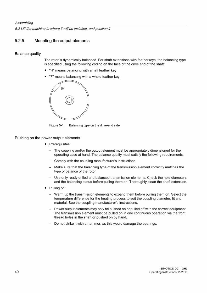
5.2.5 Mounting the output elements
Balance quality The rotor is dynamically balanced. For shaft extensions with featherkeys, the balancing type is specified using the following coding on the face of the drive end of the shaft:
● "H" means balancing with a half feather key
● "F" means balancing with a whole feather key.
Figure 5-1 Balancing type on the drive-end side
Pushing on the power output elements ● Prerequisites:
– The coupling and/or the output element must be appropriately dimensioned for the operating case at hand. The balance quality must satisfy the following requirements.
– Comply with the coupling manufacturer's instructions.
– Make sure that the balancing type of the transmission element correctly matches the type of balance of the rotor.
– Use only ready drilled and balanced transmission elements. Check the hole diameters and the balancing status before pulling them on. Thoroughly clean the shaft extension.
● Pulling on:
– Warm up the transmission elements to expand them before pulling them on. Select the temperature difference for the heating process to suit the coupling diameter, fit and material. See the coupling manufacturer's instructions.
– Power output elements may only be pushed on or pulled off with the correct equipment. The transmission element must be pulled on in one continuous operation via the front thread holes in the shaft or pushed on by hand.
– Do not strike it with a hammer, as this would damage the bearings.
Assembling5.2 Lift the machine to where it will be installed, and position it
SIMOTICS DC 1GH740 Operating Instructions 11/2013

Shaft extensions with feather key To maintain the balancing quality, you have the following options:
● If the transmission element is shorter than the feather key with balancing type "H", you must machine off the section of feather key protruding from the shaft contour and transmission element in order to maintain the balance quality.
● If the transmission element is drawn up on to the shoulder of the shaft, you must ensure that the part of the coupling groove where the feather key is not inserted is taken into consideration when balancing the coupling.
● The feather key must be shortened if the coupling hub is shorter than the feather key.
● The center of gravity of the coupling half should be within the length of the shaft end.
● The coupling used must be prepared for system balancing.The number of poles of the machine is specified on the rating plate (in the designation of the motor type).
WARNING
The feather key can fall out
The feather keys are only locked against falling out during shipping. If a machine with two shaft extensions does not have an output element on one shaft extension, the feather key can fall out during operation.
Death or serious injury can result.● Do not operate the machine unless the transmission elements have been pulled on.● On shaft extensions without output element, make sure that the feather key cannot fall
out and shorten it by approximately half for balance type "H".
5.2.6 Lifting and transporting the machineTo safely lift and transport the machine, the following requirements must be met:
● Personnel operating cranes and fork-lift trucks must be appropriately qualified.
● When lifting the machine, use only approved and undamaged sling guides and spreaders of sufficient rated capacity. Check the lifting equipment prior to its use. The weight of the machine is shown on the rating plate.
● When lifting the machine, refer to the information on the lifting plate.
– Comply with the specified spreading angles.
– Do not exceed the maximum lifting acceleration and lifting speed specified on the lifting plate. Lift the machine without jerking it.Acceleration a ≤ 3.942 m/s2 Velocity v ≤ 20 m/min
● Use only the load carrying device on the stator frame for lifting.
Assembling5.2 Lift the machine to where it will be installed, and position it
SIMOTICS DC 1GH7Operating Instructions 11/2013 41
WARNING
The machine can tip, move or fall down
If you do not transport or lift the machine in a position appropriate for its construction, the machine can tip, slip into the lifting equipment or fall down. This can result in death, serious injury or material damage.● Use only the load carrying device on the stator frame for lifting.● Use the load carrying device appropriate for the machine position. ● Use suitable rope guiding or spreading devices. The weight of the machine is shown on
the rating plate.
WARNING
The machine can tip, move or fall down
If the center of gravity of a load is not located centrally between the attachment points, the motor can tip over or slip out of the lifting equipment and fall when it is being transported or lifted. This can result in death, serious injury or material damage.● Comply with the handling instructions on the machine when transporting it.● Be aware of the possibility of different loads on the sling ropes or lifting straps and the
carrying capacity of the lifting equipment.● Always take account of the center of gravity when transporting or lifting the motor. If the
center of gravity is not located centrally between the attachment points, then position the hoisting hook above the center of gravity.
NotePlace the machine in a secure and raised position
In order to obtain easy and safe access to the underside of the machine, place it in a secure and raised position.
DANGER
Standing under suspended loads
If the lifting gear or load handling attachments were to fail, the machine could fall. This can result in death, serious injury or material damage.
Never remain under or in the immediate vicinity of the machine when it is raised.
Assembling5.2 Lift the machine to where it will be installed, and position it
SIMOTICS DC 1GH742 Operating Instructions 11/2013
5.2.7 Putting the machine down
RequirementsThe following requirements must be satisfied before placing the machine at the installation location:
● The mating faces must be clean.
● The anti-corrosion protection paint has been removed from the mating faces, such as the machine feet, flange, ...
● There is no condensation present within the machine.
Placing the machine1. Place the machine slowly and carefully at the installation location, avoiding any impacts.
5.2.8 Water drain holesIn the bearing shields at the DE and NDE, water drain holes are situated in the foot area and opposite the regreasing system. They are designed as follows:
● IP23 degree of protection: Water drain holes open
● IP54 / IP55 degree of protection: Water drain holes sealed with plastic plugs
Where drain holes in the foot area are sealed, it can be useful to remove the appropriate screws or plugs depending on the ambient and operational conditions.
NoteDegree of protection for motors with IP54 and better
Removing the plastic plug or the plug screw from motors with IP54 or better nominally lowers the degree of protection to IP44.
5.2.9 Roughly aligning the machine
RequirementThe transmission element such as a coupling half has already been pulled on.
Assembling5.2 Lift the machine to where it will be installed, and position it
SIMOTICS DC 1GH7Operating Instructions 11/2013 43
Roughly aligning the machine● For horizontal positioning, push the motor sideways across the foundation. When doing so,
ensure that the axial position is maintained.
5.3 Installing the machine
5.3.1 Safety instructions for installation
WARNING
Danger caused by inappropriate fastening material
If screws of an incorrect property class have been selected or if they have been fastened to an incorrect tightening torque, they may break or become loose. This will cause the machine to move, which could damage the bearings. The rotor could smash into the machine enclosure and machine parts could be flung out of place. This can result in death, serious injury or material damage.● Comply with the required property classes for screwed connections.● Tighten the screwed connections to the specified tightening torques.
WARNING
Tensions on the fastening parts
If the machine has not been properly aligned, this will mean the fastening parts are subjected to stress/distortion. Screws may become loose or break, the machine will move, machine parts could be flung out of place. This can result in death, serious injury or material damage.● Carefully align the machine to the driven machine.
NOTICE
Damage to the mounted parts
Mounting parts such as temperature sensors or speed sensors are attached to the machine and could be ripped off or destroyed as a result of improper handling. This could lead to machine malfunctions, extending even to total loss of the machine. ● Where necessary, use suitable steps when performing installation work on the machine.● Do not stand on cables or attachments during installation. Do not use attachments as
steps.
Assembling5.3 Installing the machine
SIMOTICS DC 1GH744 Operating Instructions 11/2013
5.3.2 Selecting fixing screws● Unless specified otherwise, use fixing bolts with at least strength class 8.8 to ISO 898‑1 to
ensure that the machine is fastened and the torque-generated forces are transmitted securely.
● When selecting the bolts and the design of the foundation, take into account the maximum forces occurring in the case of a fault such as short circuit or system transfers in phase opposition.
5.3.3 Aligning the machine to the driven machine and attaching it to it (foundation mounting)
1. Refer to any instructions for aligning the driven machine and those of the coupling manufacturer.
2. Align the machines with coupling output to the driven machine in such a manner that the center lines of the shafts are parallel with no offset. This ensures that no additional forces affect their bearings during operation.
3. For the vertical positioning (x→0), place thin shims over a large surface area under the machine feet. The number of shims should be kept as low as possible, i.e. stack as few as possible. This also prevents the machine being subjected to any stress/distortion. Use the existing tapped holes for the forcing-off bolts to raise the machine. The balance state of the shaft (full-key or half-key balancing) and alignment errors primarily influence the service life of the bearing, especially for high motor speeds or when using rigid couplings.
Assembling5.3 Installing the machine
SIMOTICS DC 1GH7Operating Instructions 11/2013 45

4. When positioning the machine, ensure that a uniform axial gap (y→0) is maintained around the coupling.
5. Fix the machine to the foundation. The choice of fixing elements depends on the foundation and is the plant operator's responsibility.
① Plates placed under the motor for alignment② Laser alignment
Figure 5-2 Schematic diagram: Aligning the machine to the driven machine
Table 5-2 Permissible deviations for aligning the machine with flexible coupling
Permissible deviations Radial shaft offset x Axial shaft offset ynmax = 1500 rpm xmax = 0.08 mm ymax = 0.08 mm / 100 mm ∅ Dnmax > 1500 rpm xmax = 0.05 mm ymax = 0.05 mm / 100 mm ∅ D
NoteMachine expansion
When performing alignment, make allowance for the thermal expansion of the machine due to rising temperature.
Assembling5.3 Installing the machine
SIMOTICS DC 1GH746 Operating Instructions 11/2013
5.3.4 Aligning the machine to the driven machine and attaching it to it (flange mounting, vertical)
The standard flange is provided with a centering. The choice of fit for the mating flange on the driven machine is the system manufacturer's or the plant operator's responsibility.
Note
If the machine is not fitted with a standard flange, align the machine to suit the driven machine.
ProcedureThe machine axis must be vertical when it is lifted and the flange must be parallel to the mating flange, so as to avoid seizing and stressing. Otherwise damage to the centering will result.
1. Grease the centering flange with assembly paste to make the process easier.
2. Screw in two studs into tapped holes on opposite sides of the driven machine flange. The studs act as positioning aids.
3. Lower the machine slowly toward the driven machine and into the centering, so that the flanges do not quite touch. Lowering too quickly risks damaging the centering.
4. If necessary, rotate the machine into the right position so that the clearance holes in the flange are central to the tapped holes.
5. Lower the machine completely onto the mating flange so that it is fully in contact; then remove the studs.
6. Fix the machine using the flange fixing bolts.
5.3.5 Aligning the machine to the driven machine and mounting (flange, horizontal IM B5)The standard flange is provided with a centering. The choice of fit for the mating flange on the driven machine is the system manufacturer's or the plant operator's responsibility.
Note
If the machine is not fitted with a standard flange, align the machine to suit the driven machine.
ProcedureThe machine axis must be horizontal when it is lifted and the flange must be parallel to the mating flange, so as to avoid seizing and stressing. Otherwise damage to the centering will result.
1. Grease the centering flange with assembly paste to make the process easier.
2. Screw three studs into tapped holes spaced about 120° apart around the driven machine flange. The studs act as positioning aids.
Assembling5.3 Installing the machine
SIMOTICS DC 1GH7Operating Instructions 11/2013 47
3. Position the machine so that its axis is aligned with that of the driven machine, but not yet quite touching. Advance the machine slowly towards the driven machine; advancing too quickly risks damaging the centering.
4. If necessary, rotate the machine into the right position so that the clearance holes in the flange are central to the tapped holes.
5. Move the machine fully up against the mating flange so that it is fully in contact.
6. Fix the machine using the flange fixing bolts, finishing by replacing the studs.
5.3.6 Mounting the machine
Secure mounting of different motor variants● For secure motor mounting, use fastening screws with the required property class per ISO
898-1, e.g. 10.9.
● On motors with an upwardly oriented shaft extension, make sure that no water enters the top bearing.
● Machines that are attached to the wall by their mounting feet because of their type must be supported from below by a wall strip, for example, or pinned.
● Install motors with a belt output on clamping bars. This provides a simple way of ensuring the correct belt tension.
Alignment accuracy The coaxial characteristic of the shafts of electrical machines and driven machine may not exceed 0.05 mm in diameter.
5.3.7 Axial and radial forcesYou can obtain the permissible values for axial and radial forces by contacting the Siemens Service Center or referring to the machine catalog.
NOTICE
Damage to bearings or the shaft
Large output masses and their centers of gravity outside the shaft extensions can lead to resonance in operation. This can result in damage to the bearings and shaft.
Ensure that the permissible loads for the forces on the shaft extension are adhered to in accordance with the catalog data or configuration data.
Assembling5.3 Installing the machine
SIMOTICS DC 1GH748 Operating Instructions 11/2013

● Use tensioning rails to set up belt-driven motors to adjust the belt to the correct tension.
CAUTION
Excessive belt tension
On machines with a belt pulley, the bearings and shaft can be damaged if the belt tension is too high.
It is essential, therefore, that the radial and axial shaft load values are within tolerance.
Assembling5.3 Installing the machine
SIMOTICS DC 1GH7Operating Instructions 11/2013 49

Assembling5.3 Installing the machine
SIMOTICS DC 1GH750 Operating Instructions 11/2013

Electrical connection 6
When carrying out any work on the machine, observe the general safety instructions (Page 13) and the specifications contained in EN 50110‑1 regarding safe operation on electrical equipment.
6.1 Selecting cablesTake the following criteria into account when selecting the connecting cables:
● Rated current
● Rated voltage
● If required, service factor
● System-dependent conditions, such as ambient temperature, routing type, cable cross-section as defined by required length of cable, etc.
● Configuration notes
● Requirements according to IEC/EN 60204‑1
6.2 Bringing in and routing the cables1. The screw-mounted entry plate is not normally supplied with holes. Make sure the type,
number, and size of the screw connections are appropriate to the specific cabling requirements.
2. Only use guide elements that meet the following requirements:
– Guide elements must be adapted to suit the type and diameter of the cables.
– Guide elements must guarantee IP55 degree of protection. The same applies to insertion points, where sealing rings and adhesive should be used.
– Guide elements must be appropriate to cable installation conditions. For example, use cable grips where cables are not securely installed.
3. Avoid chafing the cable insulation. Route the connecting cables and, in particular, the protective conductors in the terminal box so that they do not touch the machine and excess length remains.
4. Close unused cable entries with suitable seal inserts. Please ensure the following:
– The seals are made of resistant, approved material.
– The degree of protection is guaranteed. Use sealing rings or adhesive, if necessary
– Only open the cable entries with a tool.
SIMOTICS DC 1GH7Operating Instructions 11/2013 51
6.3 Terminal designationsAccording to IEC / EN 60034-8, the following basic definitions apply to the terminal designations on DC motors:
Table 6-1 Terminal designations in example B1
B 1 Designationx Code letter for winding parts (A, B, C, D, E, F) x Identification number showing winding start (1), end (2), or tapping if there is more than
one connection per winding
The terminal diagram pasted into the terminal box shows only the conditions required for connection to the line power supply, without detailed representation of inner connections or winding components.
6.4 Connecting cablesThe power cables are connected in the terminal box. Supplementary connections for auxiliary circuits with terminal strips for cable cross-sections of up to 2.5 mm2 are provided. Terminal post insulators or Terminal Boards (depending on construction type) are provided for connecting the excitation circuit.
● Terminal boxes can also be rotated by 90° in each case depending on the connecting direction. Please ensure that winding feeder cables are relaid correctly. In this case, the insulator plate does not need to be repositioned. Under difficult conditions, e.g. with large cross sections or a large number of cables, repositioning a terminal box may only be possible with restrictions or special adaptation steps may be necessary.
● Connect the cables in such a way as to ensure a permanent and reliable electrical connection. Depending on their design, the connecting parts may be suitable for connection with or without cable lugs. Use the matching cable end pieces.
● Make sure the protective conductor connection is secure.
● Comply with the rating plate data and the terminal diagram in the terminal box when making the electrical connections.
Electrical connection6.4 Connecting cables
SIMOTICS DC 1GH752 Operating Instructions 11/2013
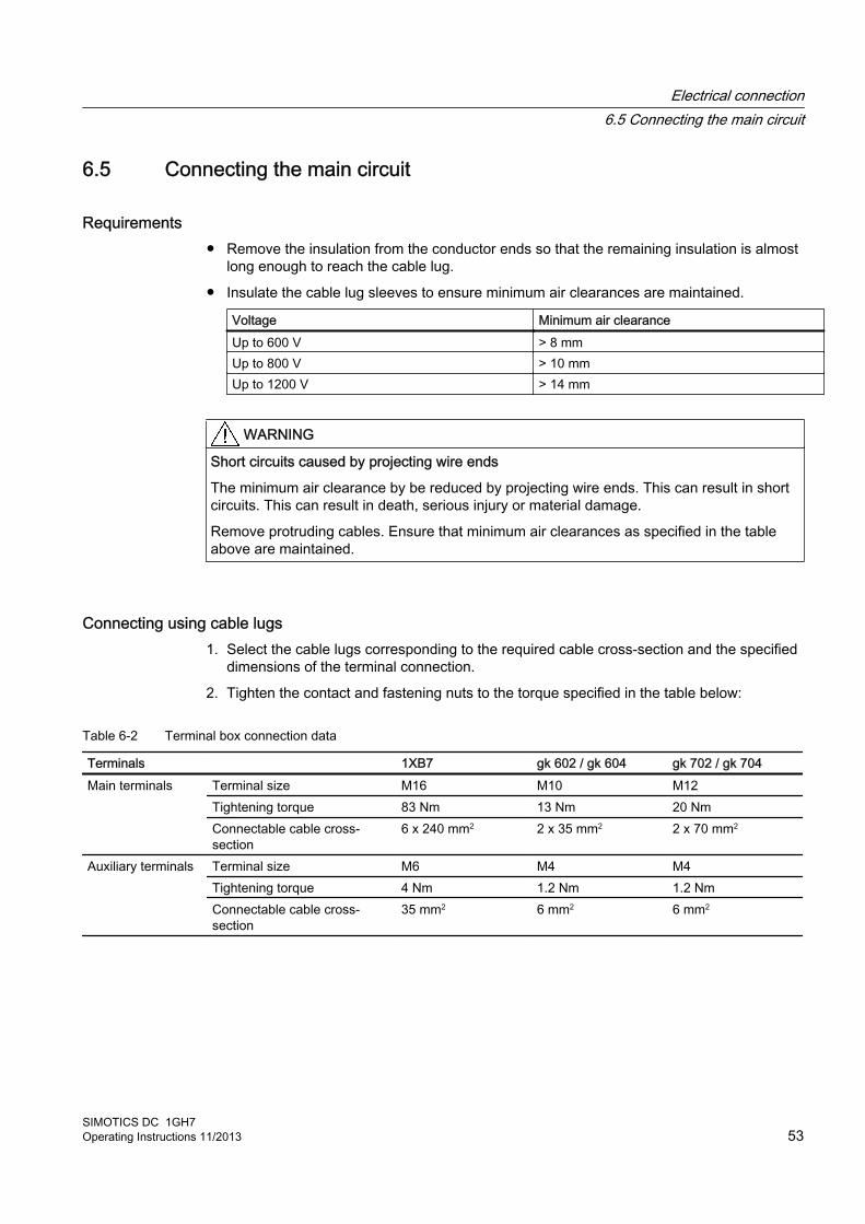
6.5 Connecting the main circuit
Requirements● Remove the insulation from the conductor ends so that the remaining insulation is almost
long enough to reach the cable lug.
● Insulate the cable lug sleeves to ensure minimum air clearances are maintained.
Voltage Minimum air clearanceUp to 600 V > 8 mmUp to 800 V > 10 mmUp to 1200 V > 14 mm
WARNING
Short circuits caused by projecting wire ends
The minimum air clearance by be reduced by projecting wire ends. This can result in short circuits. This can result in death, serious injury or material damage.
Remove protruding cables. Ensure that minimum air clearances as specified in the table above are maintained.
Connecting using cable lugs1. Select the cable lugs corresponding to the required cable cross-section and the specified
dimensions of the terminal connection.
2. Tighten the contact and fastening nuts to the torque specified in the table below:
Table 6-2 Terminal box connection data
Terminals 1XB7 gk 602 / gk 604 gk 702 / gk 704Main terminals Terminal size M16 M10 M12
Tightening torque 83 Nm 13 Nm 20 NmConnectable cable cross-section
6 x 240 mm2 2 x 35 mm2 2 x 70 mm2
Auxiliary terminals Terminal size M6 M4 M4Tightening torque 4 Nm 1.2 Nm 1.2 NmConnectable cable cross-section
35 mm2 6 mm2 6 mm2
Electrical connection6.5 Connecting the main circuit
SIMOTICS DC 1GH7Operating Instructions 11/2013 53
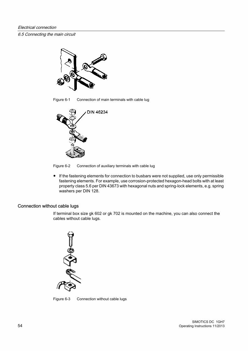
Figure 6-1 Connection of main terminals with cable lug
Figure 6-2 Connection of auxiliary terminals with cable lug
● If the fastening elements for connection to busbars were not supplied, use only permissible fastening elements. For example, use corrosion-protected hexagon-head bolts with at least property class 5.6 per DIN 43673 with hexagonal nuts and spring-lock elements, e.g. spring washers per DIN 128.
Connection without cable lugsIf terminal box size gk 602 or gk 702 is mounted on the machine, you can also connect the cables without cable lugs.
Figure 6-3 Connection without cable lugs
Electrical connection6.5 Connecting the main circuit
SIMOTICS DC 1GH754 Operating Instructions 11/2013
● The design of the terminals makes it possible to connect finely stranded conductors without the use of wire end ferrules.
● Use only wire end ferrules that have been properly crimped onto the conductor so that the full terminal clamping force holds the conductor in place. Stiff wire end ferrules, which have not yet been placed under pressure, reduce the binding power exerted on the conductor, thereby affecting the quality of the contact.
6.6 Connecting the grounding conductorThe grounding conductor cross-section of the machine must match the installation specifications, e.g. comply with IEC / EN 60204-1.
CAUTION
Damage resulting from protective conductor currents
During motor operation, PE conductor currents of up to 1.7 times the line current can arise if there is a ground fault on the output side. Neither the PE conductors of normally dimensioned multi-core connecting cables nor the PE connection points of normal terminal boxes are suitable for this purpose. This results in material damage.
Install an adequately sized parallel protective conductor and connect this to the ground terminal on the motor housing. Use only the screws supplied.
Connecting the grounding conductorA hexagon-head bolt with a spring lock washer and plain washer or a ground terminal is provided at the designated grounding conductor connection points. The hexagon bolt can be used for connecting stranded conductors with cable lugs or ribbon cables with an appropriately shaped conductor end.
When making connections, ensure the following:
● the connecting surface is bare and protected against corrosion using a suitable substance, e.g. acid-free Vaseline
● the flat and spring washers are located under the bolt head.
● The maximum permissible clamping thickness of 10 mm for the cable lug or strap is not exceeded
● The minimum required screw-in depth and the tightening torque comply with the values specified in the tables below. Different values apply to cable lugs or grounding terminals.
Table 6-3 Tightening torque of screws with cable lugs
Bolt Screw-in depth Tightening torqueM12 x 25 > 16 mm 38 NmM16 x 35 > 20 mm 92 Nm
Electrical connection6.6 Connecting the grounding conductor
SIMOTICS DC 1GH7Operating Instructions 11/2013 55
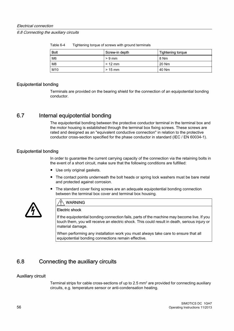
Table 6-4 Tightening torque of screws with ground terminals
Bolt Screw-in depth Tightening torqueM6 > 9 mm 8 NmM8 > 12 mm 20 NmM10 > 15 mm 40 Nm
Equipotential bondingTerminals are provided on the bearing shield for the connection of an equipotential bonding conductor.
6.7 Internal equipotential bondingThe equipotential bonding between the protective conductor terminal in the terminal box and the motor housing is established through the terminal box fixing screws. These screws are rated and designed as an "equivalent conductive connection" in relation to the protective conductor cross-section specified for the phase conductor in standard (IEC / EN 60034-1).
Equipotential bondingIn order to guarantee the current carrying capacity of the connection via the retaining bolts in the event of a short circuit, make sure that the following conditions are fulfilled:
● Use only original gaskets.
● The contact points underneath the bolt heads or spring lock washers must be bare metal and protected against corrosion.
● The standard cover fixing screws are an adequate equipotential bonding connection between the terminal box cover and terminal box housing.
WARNING
Electric shock
If the equipotential bonding connection fails, parts of the machine may become live. If you touch them, you will receive an electric shock. This could result in death, serious injury or material damage.
When performing any installation work you must always take care to ensure that all equipotential bonding connections remain effective.
6.8 Connecting the auxiliary circuits
Auxiliary circuit Terminal strips for cable cross-sections of up to 2.5 mm2 are provided for connecting auxiliary circuits, e.g. temperature sensor or anti-condensation heating.
Electrical connection6.8 Connecting the auxiliary circuits
SIMOTICS DC 1GH756 Operating Instructions 11/2013
The information required to connect the auxiliary circuits is provided in the connection diagram, located on the inside of the terminal box cover, and in the machine documentation.
The required length of stripped insulation on conductors for auxiliary terminals varies: From 6 to 9 mm depending on the terminal type. When the length is correct, the bare conductor must reach the center stop in the terminal and at the same time the conductor insulation must reach the contact part of the terminal.
Brush monitoring Signal transmitters for brush monitoring are installed, depending on the machine design.
The brush monitoring device senses the brush height limit value. Two millimeters before the minimum permissible brush height is reached, a signal is output via a switch. In normal operation and at medium speeds, you can then run your motor for another approx. 500 to 1000 hours. Replace the carbon brushes in good time.
The electrical connection requirements are shown on the terminal diagram pasted into the terminal box.
Speed sensor Electrically connect a built-on speed sensor in situ.
Temperature monitoring Avoid hazards due to unexpected, automatic restarting of the installation after the temperature protection has tripped. Implement this in the temperature evaluation and control.
WARNING
Automatic restart
Failure to ensure that the temperature monitoring prevents automatic restarting after the machine has cooled can result in death and serious personal injury due to hazardous voltage or rotating parts.
On machines with temperature sensors, design the temperature evaluation and control circuits in such a way that it is impossible for the machine to switch on and start to rotate automatically. .
6.9 Connecting temperature monitoring for the stator windingThe stator winding is monitored for thermal loading by resistance thermometers embedded in the stator winding.
Electrical connection6.9 Connecting temperature monitoring for the stator winding
SIMOTICS DC 1GH7Operating Instructions 11/2013 57

The connecting leads of the temperature sensors are routed to the terminal box. The switching and assignment of the terminals is shown on the terminal diagram in the auxiliary terminal box.
WARNING
Hazard due to electric shock
The installation of the temperature sensors for the winding monitoring with respect to the winding is implemented according to the requirements for basic insulation. The temperature sensor connections are located in terminal boxes, safe to touch, and have no protective separation. This is the reason that in the case of a fault, a hazardous voltage can be present at the measuring sensor cable. When touched, this can result in death, severe bodily injury and material damage.
When connecting the temperature sensor to external temperature monitoring devices, when required, apply additional measures to fully comply with the requirement "Hazard due to electric shock," see IEC 60664-1 or IEC 61800-5-1.
6.10 Completing connection work1. Before closing the terminal box, please check that:
– The cables and links match the terminal diagram inside the terminal box cover.
– The electrical connections in the terminal box are tight and fully comply with the specifications in the preceding chapters.
– The inside of the terminal box is clean and free of any cable debris.
– All of the clamping bolts and entry parts are securely tightened. This also applies to unused terminals.
– Minimum air clearances have been respected.
– The connecting cables are arranged so that they do not come into contact with the machine, and the cable insulation is not damaged.
– Any unused entry points are sealed. Only open the sealing elements with a tool.
– All of the seals/gaskets and sealing surfaces of the terminal box are in a good condition. If the joins are sealed purely by metal sealing surfaces, these sealing surfaces must be cleaned and lightly greased again.
– The right cable guides are fitted with respect to degree of protection, method of laying, permissible cable diameter, etc., as stated in the specifications.
– With a U-shaped terminal box casing, the entry plate is aligned and secured in such a way that the seat for the box cover seal is continuous all the way round.
2. Then close the terminal box. Tightening torque for the cover fastening screws is 22 Nm.
Electrical connection6.10 Completing connection work
SIMOTICS DC 1GH758 Operating Instructions 11/2013
Commissioning 7
When carrying out any work on the machine, observe the general safety instructions (Page 13) and the specifications contained in EN 50110‑1 regarding working safely with and on electrical machines.
NoteService Center
Please contact the Service Center (Page 117), if you require commissioning support.
7.1 Preparing for commissioningOnce the system has been correctly installed, you should check the following prior to commissioning:
● The motor has been assembled and aligned properly.
● The rotor is fully able to turn and does not contact other parts at any point during rotation.
● The bearings have been regreased as appropriate for the model.
● All electrical and mechanical connections are secure. The function is assured.
● All fixing screws, connecting elements and electrical connections are firmly tightened.
● The cover sheets have been remounted correctly to ensure effective cooling of the motor.
● The operating conditions correspond to the data specified on the rating plate.
● Any supplementary motor monitoring devices have been correctly connected.
● The machine is connected up appropriately for the specified direction of rotation.
● Appropriately configured control and speed monitoring functions ensure that the motor cannot exceed the permissible speeds specified on the rating plate.
● If the motor is operated continuously under light-load conditions of I < 50 %, there is a risk of high brush wear or problems with the commutator. Please consult the manufacturer if this type of operation is intended. The power output elements have the proper setting conditions according to type, for example:
– Couplings are aligned and balanced.
– The belt tension is properly adjusted if there is a belt drive.
– Gear tooth flank play and gear tooth tip play, as well as radial play, are properly adjusted if there is a gearwheel output.
● The minimum insulation resistance values are within tolerance.
SIMOTICS DC 1GH7Operating Instructions 11/2013 59
● If the bearings are insulated, the insulation has not been bridged.
● The grounding and equipotential bonding connections have been established correctly.
● Moving and energized parts are guarded with touch protection.
● If the second shaft extension has not been used, its featherkey has been secured to prevent it from being thrown out.
● All external fans are ready for operation and have been connected so that they rotate in the direction specified.
● The flow of cooling air is not impeded.
● If closed-circuit air-to-water cooling is installed, the heat exchanger is connected, filled, air bled, and ready to run. This also applies after prolonged periods of non-operation.All brakes are operating correctly.
● Carbon brushes and brush levers can move freely in the brush guides. The spring action is identical on all carbon brushes.
It may be necessary to perform additional checks and tests in accordance with the situation specific to the particular place of installation.
Commissioning converters● Commission the converter as described in its operating instructions before commissioning
the motor. Be aware of the motor parameters.
● Make sure any work done is documented on the correct checklist.
7.2 Insulation resistance and polarization indexMeasuring the insulation resistance and polarization index (PI) provides information on the condition of the machine. It is therefore important to check the insulation resistance and the polarization index at the following times:
● Before starting up a machine for the first time
● After an extended period in storage or downtime
● Within the scope of maintenance work
The following information is provided regarding the state of the winding insulation:
● Is the winding head insulation conductively contaminated?
● Has the winding insulation absorbed moisture?
As such, you can determine whether the machine needs commissioning or any necessary measures such as cleaning and/or drying the winding:
● Can the machine be put into operation?
● Must the windings be cleaned or dried?
Detailed information on testing and the limit values can be found here:
"Testing the insulation resistance and polarization index" (Page 35)
Commissioning7.2 Insulation resistance and polarization index
SIMOTICS DC 1GH760 Operating Instructions 11/2013
7.3 Greasing the roller bearings prior to commissioningThe following information assumes that the specified storage conditions have been complied with.
General specifications● Pay attention to the instructions on the lubricant plate.
● Regrease in portions. The shaft must rotate so that the new grease can be distributed in the bearings.
Regreasing the roller bearings prior to commissioning ● If the period between delivery and commissioning is more than a year and less than four
years:
– Re-grease the roller bearings with twice the amount of grease specified on the lubricant plate.
– Check the bearing temperature, as far as possible.
Regreasing roller bearings before commissioning You must regrease the roller bearings under the following conditions:
● If the machine has been in storage for more than four years.
● If the machine has not been stored in accordance with the specifications in the "Storage" section.
Procedure1. Remove the bearing, regreasing pipes, grease nipples and the bearing cap.
2. Flush out the old grease.
3. Check the bearings before regreasing. If necessary, install new bearings.
4. Lubricate the bearings and reinstall the bearing components.
7.4 Minimum radial forces for cylindrical roller bearings
NoteMaintaining the minimum radial forces
Operating roller bearings without a load can damage them. Maintain the minimum radial forces specified when using cylindrical roller bearings.
Commissioning7.4 Minimum radial forces for cylindrical roller bearings
SIMOTICS DC 1GH7Operating Instructions 11/2013 61
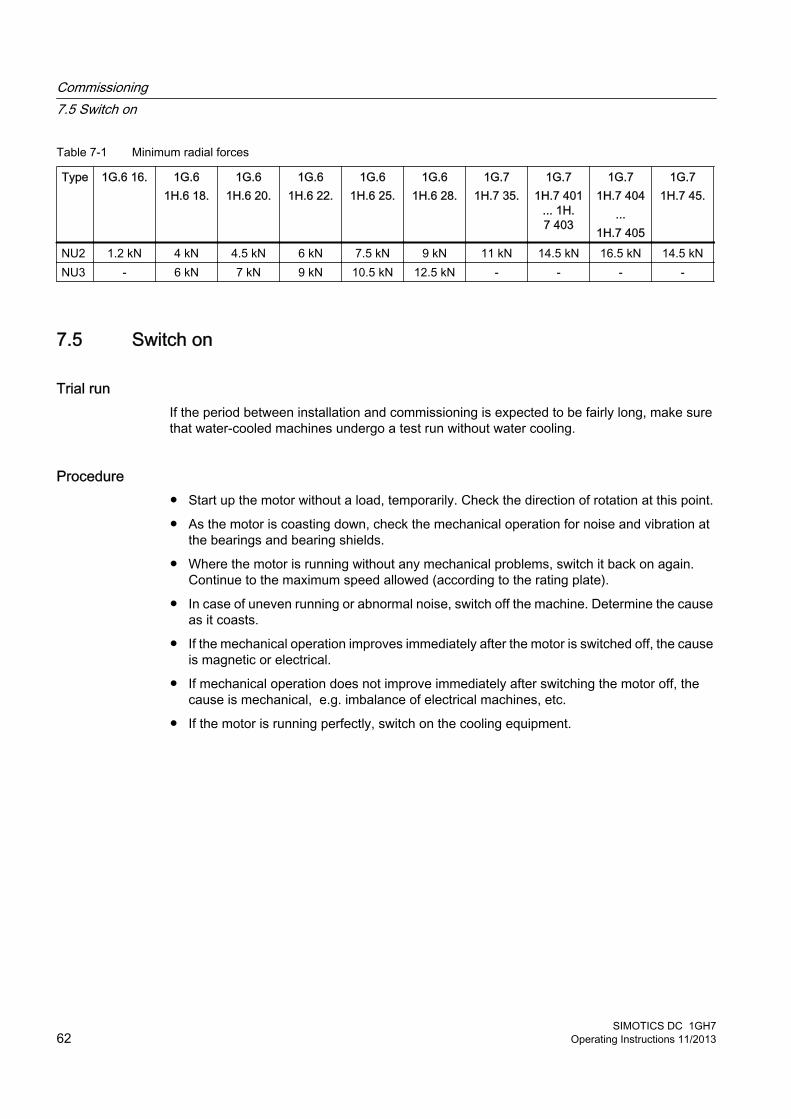
Table 7-1 Minimum radial forces
Type 1G.6 16. 1G.61H.6 18.
1G.61H.6 20.
1G.61H.6 22.
1G.61H.6 25.
1G.61H.6 28.
1G.71H.7 35.
1G.71H.7 401
... 1H.7 403
1G.71H.7 404
...1H.7 405
1G.71H.7 45.
NU2 1.2 kN 4 kN 4.5 kN 6 kN 7.5 kN 9 kN 11 kN 14.5 kN 16.5 kN 14.5 kNNU3 - 6 kN 7 kN 9 kN 10.5 kN 12.5 kN - - - -
7.5 Switch on
Trial runIf the period between installation and commissioning is expected to be fairly long, make sure that water-cooled machines undergo a test run without water cooling.
Procedure● Start up the motor without a load, temporarily. Check the direction of rotation at this point.
● As the motor is coasting down, check the mechanical operation for noise and vibration at the bearings and bearing shields.
● Where the motor is running without any mechanical problems, switch it back on again. Continue to the maximum speed allowed (according to the rating plate).
● In case of uneven running or abnormal noise, switch off the machine. Determine the cause as it coasts.
● If the mechanical operation improves immediately after the motor is switched off, the cause is magnetic or electrical.
● If mechanical operation does not improve immediately after switching the motor off, the cause is mechanical, e.g. imbalance of electrical machines, etc.
● If the motor is running perfectly, switch on the cooling equipment.
Commissioning7.5 Switch on
SIMOTICS DC 1GH762 Operating Instructions 11/2013

● Observe the motor for a while during no-load operation.
NOTICE
Overheating during test runs without water cooling
The motor can overheat without water cooling. Reduce the ON duration accordingly if the water cooler is not to be operated during a test run.
● If it runs perfectly, connect a load.
– Check whether it is running smoothly.
– Record the voltage, current, and power values.
– As far as possible, record the corresponding values of the driven machine.
– Monitor and record the temperatures of the bearings, windings, and so on until the system reaches a steady state.
See alsoSwitching on (Page 132)
7.6 Overspeed
DANGER
Overspeed
When the exciter circuit is deactivated, the machine can enter operating conditions that destroy the machine. Death, serious injury, or material damage will result.● Interlock the control in such a way that the armature circuit can be connected only when
the exciter circuit is energized. ● If the exciter circuit fails, switch off the armature circuit immediately.
See alsoSafety notes (Page 13)
7.7 Switch offSwitch-off is usually initiated and controlled by an automatic control. If the machine is not switched off by a control, proceed as follows:
1. Switch the machine off.
2. Switch off any external fans.
Commissioning7.7 Switch off
SIMOTICS DC 1GH7Operating Instructions 11/2013 63

3. Switch off the coolant supply. Follow the operating instructions provided by the manufacturer.
4. Switch on the anti-condensation heating.
Commissioning7.7 Switch off
SIMOTICS DC 1GH764 Operating Instructions 11/2013

Operation 8
When carrying out any work on the machine, observe the general safety instructions (Page 13) and the specifications contained in EN 50110‑1 regarding safe operation on electrical equipment.
WARNING
Live parts
Terminal boxes contain live electrical parts. If you open the terminal box cover, this can result in death, serious injury or material damage.
When the machine is in operation, the terminal boxes must remain closed at all times. Terminal boxes may be opened only when the machine is stopped and de-energized.
WARNING
Rotating and live parts
Rotating or live parts are dangerous. If you remove the required covers, this can result in death, serious injury or material damage.
Any covers that prevent live electrical or rotating parts from being touched, ensure compliance with a particular degree of protection or are required for ensuring proper air flows, and hence effective cooling, must not be opened during operation.
WARNING
Fire hazard resulting from hot surfaces
Certain parts of the machine become hot during operation. Severe burns can result from contact with these parts.● Check the temperature of parts before touching them. If required, apply suitable protective
measures.● Allow the machine to cool before starting work on the machine.
SIMOTICS DC 1GH7Operating Instructions 11/2013 65
WARNING
Faults in operation
Deviations from normal operation such as increased power consumption, temperatures or vibrations, unusual noises or odors, tripping of monitoring devices, etc., indicate that the machine is not functioning properly. This can cause faults which can result in eventual or immediate death, serious injury or material damage. ● Immediately inform the maintenance personnel.● If you are in doubt, immediately switch off the motor, being sure to observe the system-
specific safety conditions.
NOTICE
Risk of corrosion due to condensate
Humid air can condense inside the machine during operation as a result of intermittent duty or load fluctuations. Condensate can collect inside the motor. Damage such as rust can result.
Make sure that any condensation can drain away freely.
NOTICE
Operating the motor at the natural installation frequency
Operating the motor at the natural installation frequency can lead to damage to both the motor and the foundation.
Do not operate the motor at the natural installation frequency.
DANGER
Overspeed
When the exciter circuit is deactivated, the machine can enter operating conditions that destroy the machine. Death, serious injury, or material damage will result.● Interlock the control in such a way that the armature circuit can be connected only when
the exciter circuit is energized. ● If the exciter circuit fails, switch off the armature circuit immediately.
Operation
SIMOTICS DC 1GH766 Operating Instructions 11/2013
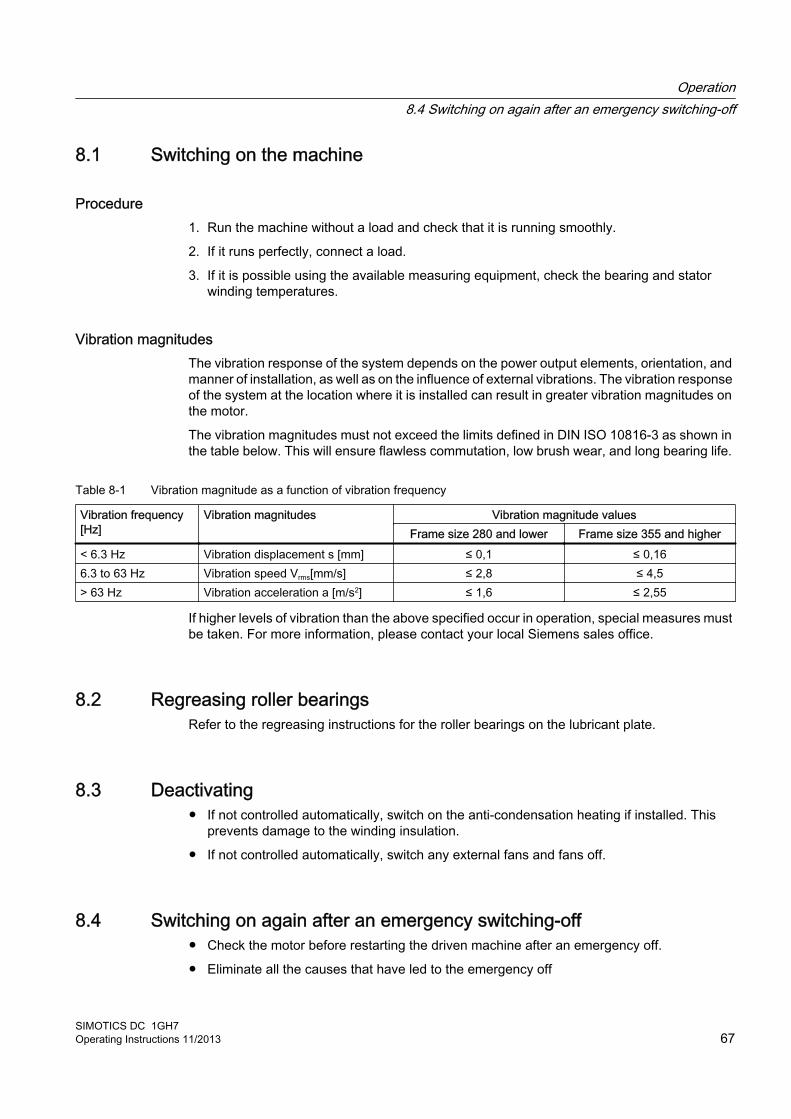
8.1 Switching on the machine
Procedure1. Run the machine without a load and check that it is running smoothly.
2. If it runs perfectly, connect a load.
3. If it is possible using the available measuring equipment, check the bearing and stator winding temperatures.
Vibration magnitudesThe vibration response of the system depends on the power output elements, orientation, and manner of installation, as well as on the influence of external vibrations. The vibration response of the system at the location where it is installed can result in greater vibration magnitudes on the motor.
The vibration magnitudes must not exceed the limits defined in DIN ISO 10816-3 as shown in the table below. This will ensure flawless commutation, low brush wear, and long bearing life.
Table 8-1 Vibration magnitude as a function of vibration frequency
Vibration frequency [Hz]
Vibration magnitudes Vibration magnitude valuesFrame size 280 and lower Frame size 355 and higher
< 6.3 Hz Vibration displacement s [mm] ≤ 0,1 ≤ 0,166.3 to 63 Hz Vibration speed Vrms[mm/s] ≤ 2,8 ≤ 4,5> 63 Hz Vibration acceleration a [m/s2] ≤ 1,6 ≤ 2,55
If higher levels of vibration than the above specified occur in operation, special measures must be taken. For more information, please contact your local Siemens sales office.
8.2 Regreasing roller bearingsRefer to the regreasing instructions for the roller bearings on the lubricant plate.
8.3 Deactivating● If not controlled automatically, switch on the anti-condensation heating if installed. This
prevents damage to the winding insulation.
● If not controlled automatically, switch any external fans and fans off.
8.4 Switching on again after an emergency switching-off● Check the motor before restarting the driven machine after an emergency off.
● Eliminate all the causes that have led to the emergency off
Operation8.4 Switching on again after an emergency switching-off
SIMOTICS DC 1GH7Operating Instructions 11/2013 67
8.5 Stoppages
The stoppage is a shutdown for a period of time, during which the machine is stopped but remains at the location of use.
Under normal ambient conditions, e. g. the stopped machine is not exposed to any vibration, no increased level of corrosion, etc. in general, the following measures are necessary during stoppages.
8.5.1 Measures in non-operational periods● Keep the motor dry using anti-condensation heating.
● After prolonged periods of non-operation and during commissioning at very low ambient temperatures (≤ 0 °C), the anti-condensation heating is not sufficient. Therefore, heat the interior of the machine additionally by heating the field winding with 30 % of the rated field current without ventilation for at least 30 minutes. This will keep the interior of the motor free of ice and dry.
● Take care with motors using water cooling to avoid possible problems with corrosion and freezing. Follow the operating instructions provided by the heat exchanger manufacturer.
● During prolonged periods of non-operation, operate the motor regularly, at least once monthly. Alternatively, turn the rotor as a minimum.
NOTICE
Bearing damage due to external factors
Where cylindrical-roller bearings are used, bearing damage can be caused by external vibration.
Consult the manufacturer for details of suitable corrective action.
NOTICE
Damage due to improper storage
Damage may occur to the motor if it is not stored properly.
If the machine is to be taken out of operation for more than 12 months, suitable anti-corrosion, preservation, packaging, and drying measures must be taken.
Decommissioning You will find detailed information about the necessary measures to be taken in the "Transportation and storage (Page 25)" section.
Operation8.5 Stoppages
SIMOTICS DC 1GH768 Operating Instructions 11/2013

Recommissioning ● When restarting the motor after a long period of non-operation, perform the measures
recommended in section "Commissioning (Page 59)."
● If the machine has been non-operational for longer than a year, regrease the bearings before commissioning. Turn the shaft to distribute the grease in the bearings.
● Pay attention to the instructions on the lubricant plate.
8.5.2 Avoidance of damage to roller bearings during stoppagesExtended stoppages at the identical or almost identical resting position of the roller bearings can lead to damage such as brinelling or formation of corrosion.
● During stoppages, regularly start the machine up for a brief period once a month, or at least turn the rotor over several times.If you have uncoupled the machine from the driven machine and secured the rotor with a rotor shipping brace, then remove this before turning the rotor over or starting the machine up.Make sure that the resting position of the roller bearings after the rotor has been turned over is different from what it previously had been. Use the fitted key or the coupling halves as reference markers.
● During re-commissioning, refer to the information in the "Commissioning" section.
8.5.3 Measurement of the insulation resistance after an extended stoppageMeasuring the insulation resistance and polarization index (PI) provides information on the condition of the machine. It is therefore important to check the insulation resistance and the polarization index at the following times:
● Before starting up a machine for the first time
● After an extended period in storage or downtime
● Within the scope of maintenance work
The following information is provided regarding the state of the winding insulation:
● Is the winding head insulation conductively contaminated?
● Has the winding insulation absorbed moisture?
As such, you can determine whether the machine needs commissioning or any necessary measures such as cleaning and/or drying the winding:
● Can the machine be put into operation?
● Must the windings be cleaned or dried?
Detailed information on testing and the limit values can be found here:
"Testing the insulation resistance and polarization index" (Page 35)
Operation8.5 Stoppages
SIMOTICS DC 1GH7Operating Instructions 11/2013 69
8.6 Decommissioning the machine
NOTICE
Damage as a result of an extended period out of service
If the machine is going to be out of service for longer than six months, then perform the necessary measures for anti-corrosion protection, preservation, packaging and drying. Otherwise damage to the machine will result.
Record the decommissioning steps. This log will be useful upon recommissioning.
8.7 Re-commissioning the machineWhen you re-commission the machine, proceed as follows:
● Study the record made when the machine was decommissioned, and reverse the measures that were taken for conservation and storage.
● Perform the measures listed in the "Commissioning" section.
8.8 Special operating conditions
Operating under light-load conditionsIf a machine is operated continuously or over a long period under light-load conditions with approximately half rated current or less, damage will occur. High brush wear or problems with the commutator may result. For more information, please refer to chapter "Faults".
If the motor is to be operated continuously under light-load conditions, consult the manufacturer.
Loading at standstillLoad stationary DC motors with armature current only for short periods so as to protect the commutator against damage. Obtain the permissible current and time values for loading at standstill from the manufacturer.
See alsoFaults (Page 71)
Operation8.8 Special operating conditions
SIMOTICS DC 1GH770 Operating Instructions 11/2013

8.9 Faults
8.9.1 Inspections in the event of faultsNatural disasters or unusual operating conditions, such as overloading or short circuit, are faults that overload the machine electrically or mechanically.
Immediately perform an inspection after such faults.
Correct the cause of the fault as described in the respective remedial measures section. Repair any damage to the machine.
Operation8.9 Faults
SIMOTICS DC 1GH7Operating Instructions 11/2013 71
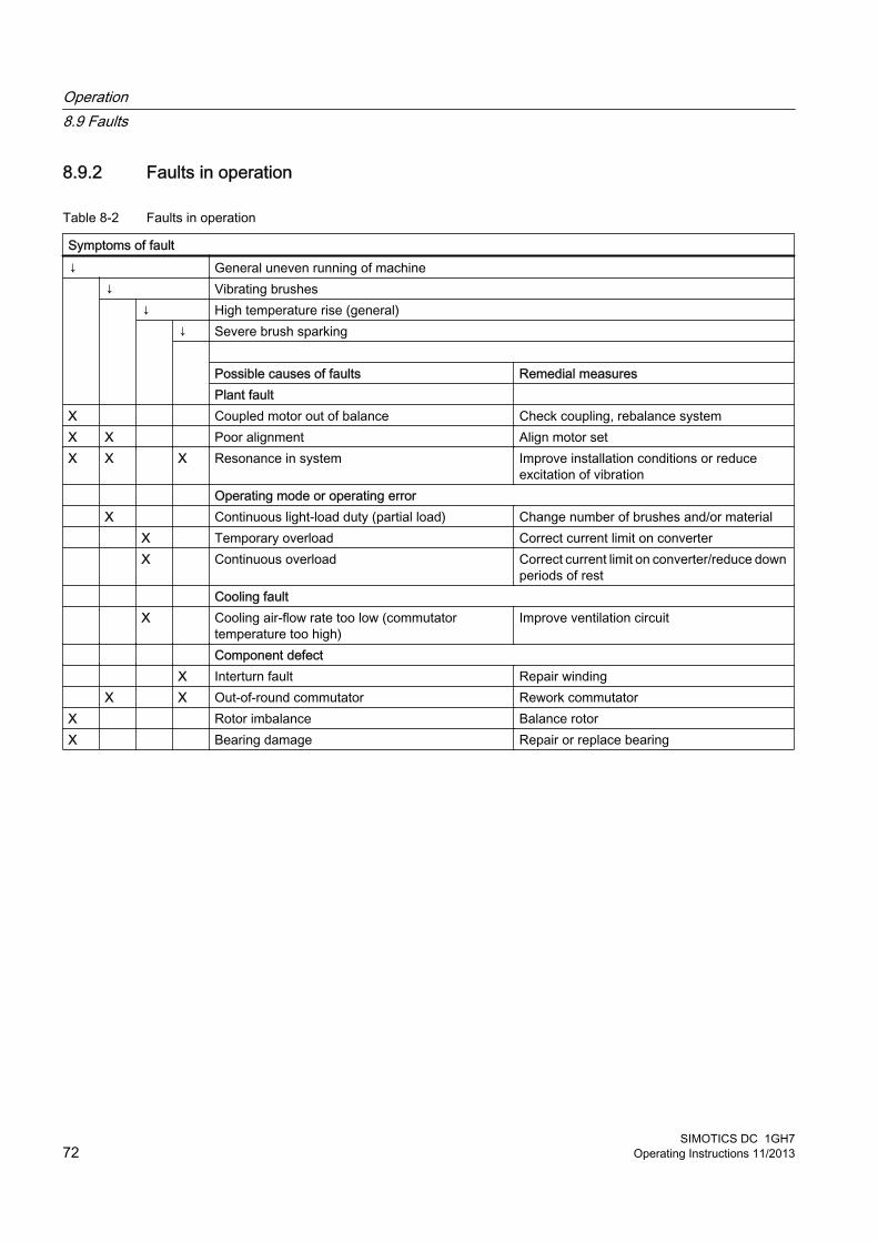
8.9.2 Faults in operation
Table 8-2 Faults in operation
Symptoms of fault↓ General uneven running of machine ↓ Vibrating brushes
↓ High temperature rise (general) ↓ Severe brush sparking
Possible causes of faults Remedial measures Plant fault
X Coupled motor out of balance Check coupling, rebalance systemX X Poor alignment Align motor setX X X Resonance in system Improve installation conditions or reduce
excitation of vibration Operating mode or operating error X Continuous light-load duty (partial load) Change number of brushes and/or material X Temporary overload Correct current limit on converter X Continuous overload Correct current limit on converter/reduce down
periods of rest Cooling fault X Cooling air-flow rate too low (commutator
temperature too high)Improve ventilation circuit
Component defect X Interturn fault Repair winding X X Out-of-round commutator Rework commutatorX Rotor imbalance Balance rotorX Bearing damage Repair or replace bearing
Operation8.9 Faults
SIMOTICS DC 1GH772 Operating Instructions 11/2013

8.9.3 Roller bearing faults
Note
Damage to roller bearings can be difficult to detect in some cases. If in doubt, replace the bearing. Use other bearing designs only after consulting the manufacturer.
Table 8-3 Roller bearing faults
↓ Bearing overheats ↓ Bearing "whistles"
↓ Bearing "knocks" Possible causes of faults Remedial measures
X High coupling pressure Align the machine more accurately.X Belt tension too high Reduce the drive belt tension.X Bearing contaminated Clean the bearing or replace it. Check the seals.X High ambient temperature Use a suitable high-temperature grease.X X Insufficient lubrication Grease the bearings as instructed.X X Bearing canted Properly install the bearing.X X Insufficient bearing play Only after consultation with the manufacturer: Fit a bearing with
greater play. X Excessive bearing play Only after consultation with the manufacturer: Fit a bearing with
lower play.X X Bearing corroded Replace the bearing. Check the seals.X Too much grease in bearing Remove surplus grease.X Wrong grease in the bearing Use the correct grease. X Friction marks on raceway Replace the bearing. X Scoring (brinelling) Replace the bearing. Avoid any vibration at standstill
Operation8.9 Faults
SIMOTICS DC 1GH7Operating Instructions 11/2013 73
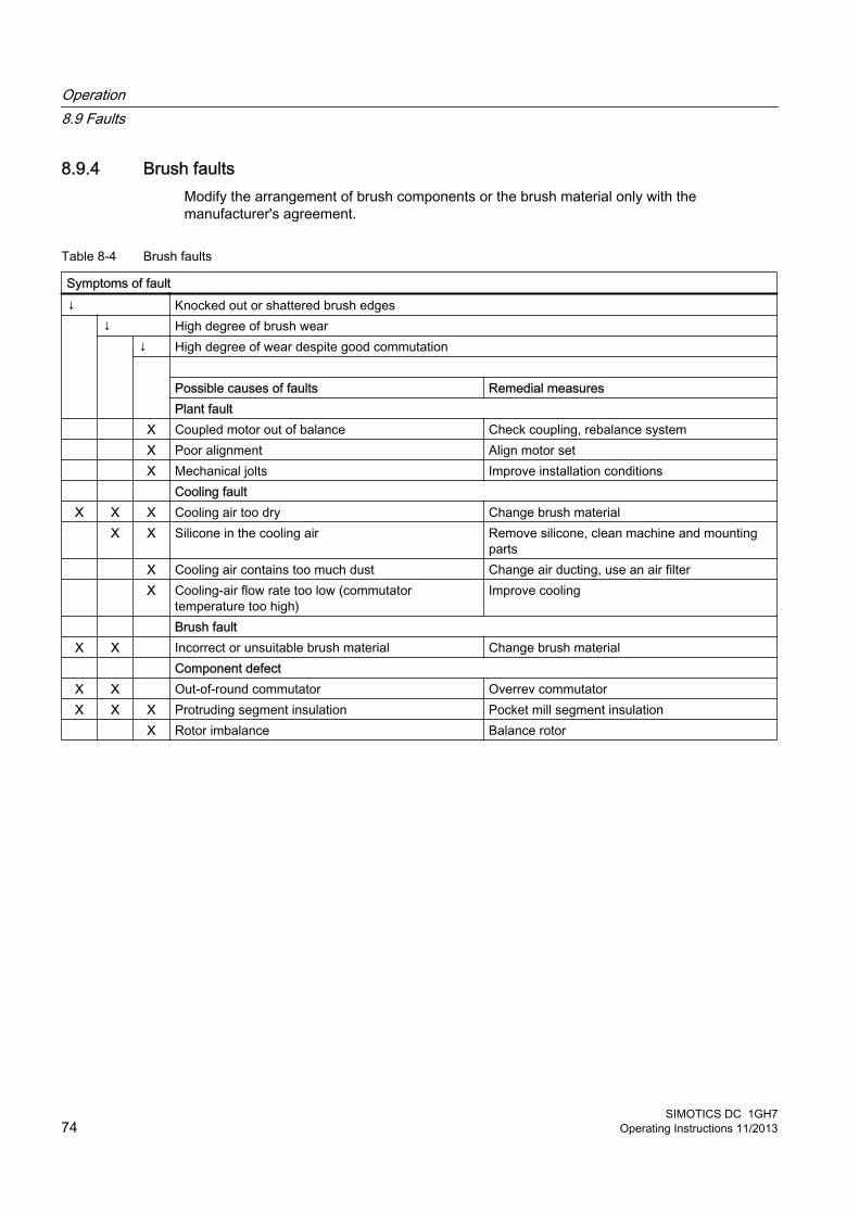
8.9.4 Brush faultsModify the arrangement of brush components or the brush material only with the manufacturer's agreement.
Table 8-4 Brush faults
Symptoms of fault↓ Knocked out or shattered brush edges ↓ High degree of brush wear
↓ High degree of wear despite good commutation
Possible causes of faults Remedial measuresPlant fault
X Coupled motor out of balance Check coupling, rebalance system X Poor alignment Align motor set X Mechanical jolts Improve installation conditions Cooling faultX X X Cooling air too dry Change brush material X X Silicone in the cooling air Remove silicone, clean machine and mounting
parts X Cooling air contains too much dust Change air ducting, use an air filter X Cooling-air flow rate too low (commutator
temperature too high)Improve cooling
Brush faultX X Incorrect or unsuitable brush material Change brush material Component defectX X Out-of-round commutator Overrev commutatorX X X Protruding segment insulation Pocket mill segment insulation X Rotor imbalance Balance rotor
Operation8.9 Faults
SIMOTICS DC 1GH774 Operating Instructions 11/2013
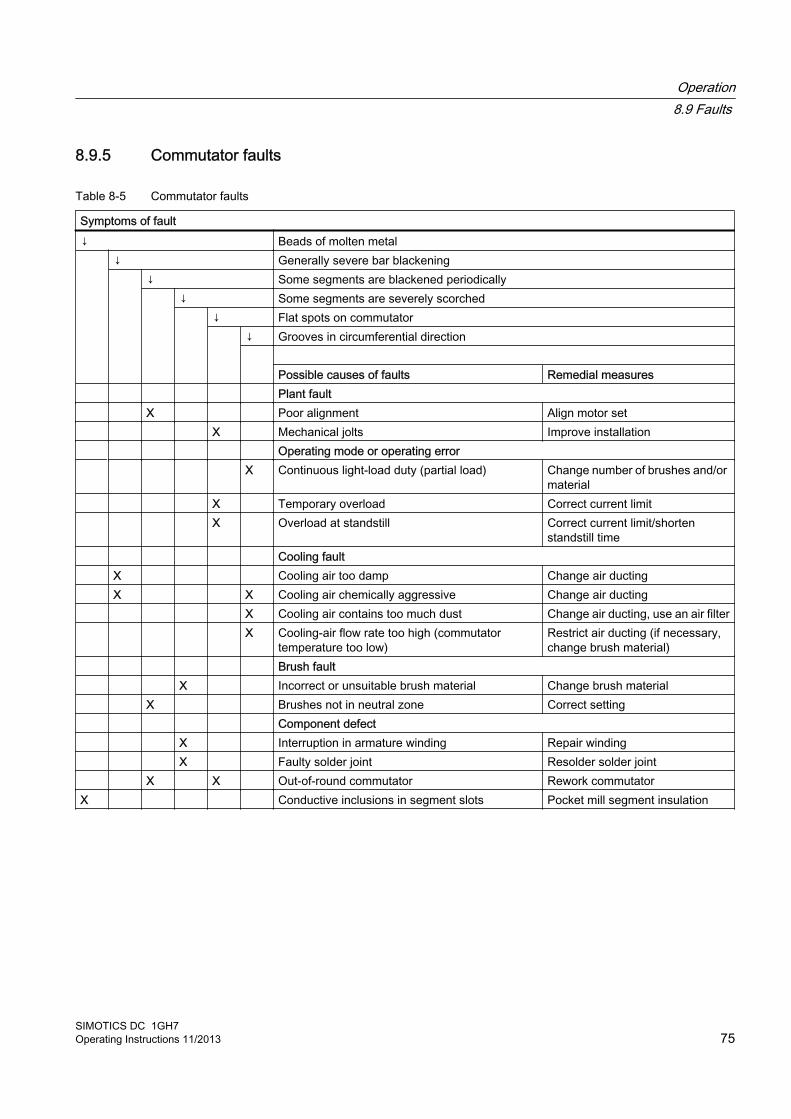
8.9.5 Commutator faults
Table 8-5 Commutator faults
Symptoms of fault↓ Beads of molten metal ↓ Generally severe bar blackening
↓ Some segments are blackened periodically ↓ Some segments are severely scorched
↓ Flat spots on commutator ↓ Grooves in circumferential direction
Possible causes of faults Remedial measures
Plant fault X Poor alignment Align motor set X Mechanical jolts Improve installation Operating mode or operating error X Continuous light-load duty (partial load) Change number of brushes and/or
material X Temporary overload Correct current limit X Overload at standstill Correct current limit/shorten
standstill time Cooling fault X Cooling air too damp Change air ducting X X Cooling air chemically aggressive Change air ducting X Cooling air contains too much dust Change air ducting, use an air filter X Cooling-air flow rate too high (commutator
temperature too low)Restrict air ducting (if necessary, change brush material)
Brush fault X Incorrect or unsuitable brush material Change brush material X Brushes not in neutral zone Correct setting Component defect X Interruption in armature winding Repair winding X Faulty solder joint Resolder solder joint X X Out-of-round commutator Rework commutatorX Conductive inclusions in segment slots Pocket mill segment insulation
Operation8.9 Faults
SIMOTICS DC 1GH7Operating Instructions 11/2013 75

Operation8.9 Faults
SIMOTICS DC 1GH776 Operating Instructions 11/2013
Maintenance 9
Through careful and regular maintenance, inspections, and overhauls you can detect faults at an early stage and resolve them. This means that you can avoid consequential damage.
Operating conditions and characteristics can vary widely. For this reason, only general maintenance intervals can be specified here. Maintenance intervals should therefore be scheduled to suit the local conditions (dirt, starting frequency, load, etc.).
When carrying out any work on the machine, observe the general safety instructions (Page 13) and the specifications contained in EN 50110‑1 regarding safe operation on electrical equipment.
NoteService Center
Please contact the Service Center, if you require support with servicing, maintenance or repair.
9.1 Inspection and maintenance
WARNING
Rotating and live parts
Electric machines contain live and rotating parts. Fatal or serious injuries and substantial material damage can occur if maintenance work is performed on the machine when it is not stopped or not de-energized.● Perform maintenance work on the machine only when it is stopped. The only operation
permissible while the machine is rotating is regreasing the roller bearings.● When performing maintenance work, comply with the five safety rules (Page 13).
WARNING
Machine damage
If the machine is not maintained it can suffer damage. This can cause faults which can result in eventual or immediate death, serious injury or material damage.
Perform regular maintenance on the machine.
SIMOTICS DC 1GH7Operating Instructions 11/2013 77
CAUTION
Dust disturbances when working with compressed air
When cleaning with compressed air, dust, metal chips, or cleaning agents can be whirled up. Injuries can result.
When cleaning using compressed air, make sure you use suitable extraction equipment and wear protective equipment (safety goggles, protective suit, etc.).
NOTICE
Damage to insulation
If metal swarf enters the winding head when cleaning with compressed air, this can damage the insulation. Clearance and creepage distances can be undershot. This may cause damage to the machine extending to total failure.
When cleaning with compressed air, ensure there is adequate extraction.
NOTICE
Machine damage caused by foreign bodies
Foreign bodies such as dirt, tools or loose components, such as screws etc., can be left by accident inside the machine after maintenance is performed. These can cause short circuits, reduce the performance of the cooling system or increase noise in operation. They can also damage the machine.● When carrying out maintenance work, make sure that no foreign bodies are left in or on
the machine.● Securely attach all loose parts again once you have completed the maintenance
procedures.● Carefully remove any dirt.
Note
Operating conditions and characteristics can vary widely. For this reason, only general intervals for inspection and maintenance measures can be specified here.
9.1.1 Initial inspection● Perform the initial inspection after installing or commissioning the motor. Normally the initial
inspection is only necessary after approx. 500 hours of operation.
● Perform follow-up inspections after every approx. 2,000 hours of operation.
Maintenance9.1 Inspection and maintenance
SIMOTICS DC 1GH778 Operating Instructions 11/2013
DANGER
Rotating or live parts
Rotating or live parts are dangerous. Death, serious injury, or material damage can result if the required covers are removed.
Depending on the design, the motor may have inspection windows for monitoring the commutation behavior or covers. If there are no inspection windows, only qualified personnel is permitted to remove the covers. This ensures that there is no contact with live or moving parts. Wear safety goggles when working.
Checking the motor when in operationThe following must be checked during the first and any subsequent inspections:
● The relevant technical data are observed: power consumption, temperature of windings, bearings, coolants, etc.
● There should be no oil, grease, or water leakages.
● The smooth running characteristics and motor running noise have not deteriorated.
● No impermissible brush sparking occurs in operation.
Checking during idle timeOnce the machine has been shut down, check that:
● The motor foundation has no indentations or cracks.
● The carbon brushes and commutators are in perfect condition. Commutator surfaces have an even finish.
● The brush holders are correctly aligned and mounted.
● Carbon brushes can move freely in the brush guides, and their pressure fingers can move freely in the articulated joints. The spring effect is consistent for all carbon brushes.
● There is sufficient brush height remaining to allow fault-free operation until the next inspection. The brush height must be reduced to below the minimum.
● Any defects discovered during checking should be fully corrected.
Note
The inspection measures may be required depending on the plant specification and operating conditions.
See alsoInspection at standstill (Page 134)
Maintenance9.1 Inspection and maintenance
SIMOTICS DC 1GH7Operating Instructions 11/2013 79
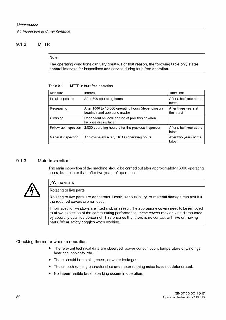
9.1.2 MTTR
Note
The operating conditions can vary greatly. For that reason, the following table only states general intervals for inspections and service during fault-free operation.
Table 9-1 MTTR in fault-free operation
Measure Interval Time limitInitial inspection After 500 operating hours After a half year at the
latestRegreasing After 1000 to 16 000 operating hours (depending on
bearings and operating mode)After three years at the latest
Cleaning Dependent on local degree of pollution or when brushes are replaced
Follow-up inspection 2,000 operating hours after the previous inspection After a half year at the latest
General inspection Approximately every 16 000 operating hours After two years at the latest
9.1.3 Main inspectionThe main inspection of the machine should be carried out after approximately 16000 operating hours, but no later than after two years of operation.
DANGER
Rotating or live parts
Rotating or live parts are dangerous. Death, serious injury, or material damage can result if the required covers are removed.
If no inspection windows are fitted and, as a result, the appropriate covers need to be removed to allow inspection of the commutating performance, these covers may only be dismounted by specially qualified personnel. This ensures that there is no contact with live or moving parts. Wear safety goggles when working.
Checking the motor when in operation● The relevant technical data are observed: power consumption, temperature of windings,
bearings, coolants, etc.
● There should be no oil, grease, or water leakages.
● The smooth running characteristics and motor running noise have not deteriorated.
● No impermissible brush sparking occurs in operation.
Maintenance9.1 Inspection and maintenance
SIMOTICS DC 1GH780 Operating Instructions 11/2013
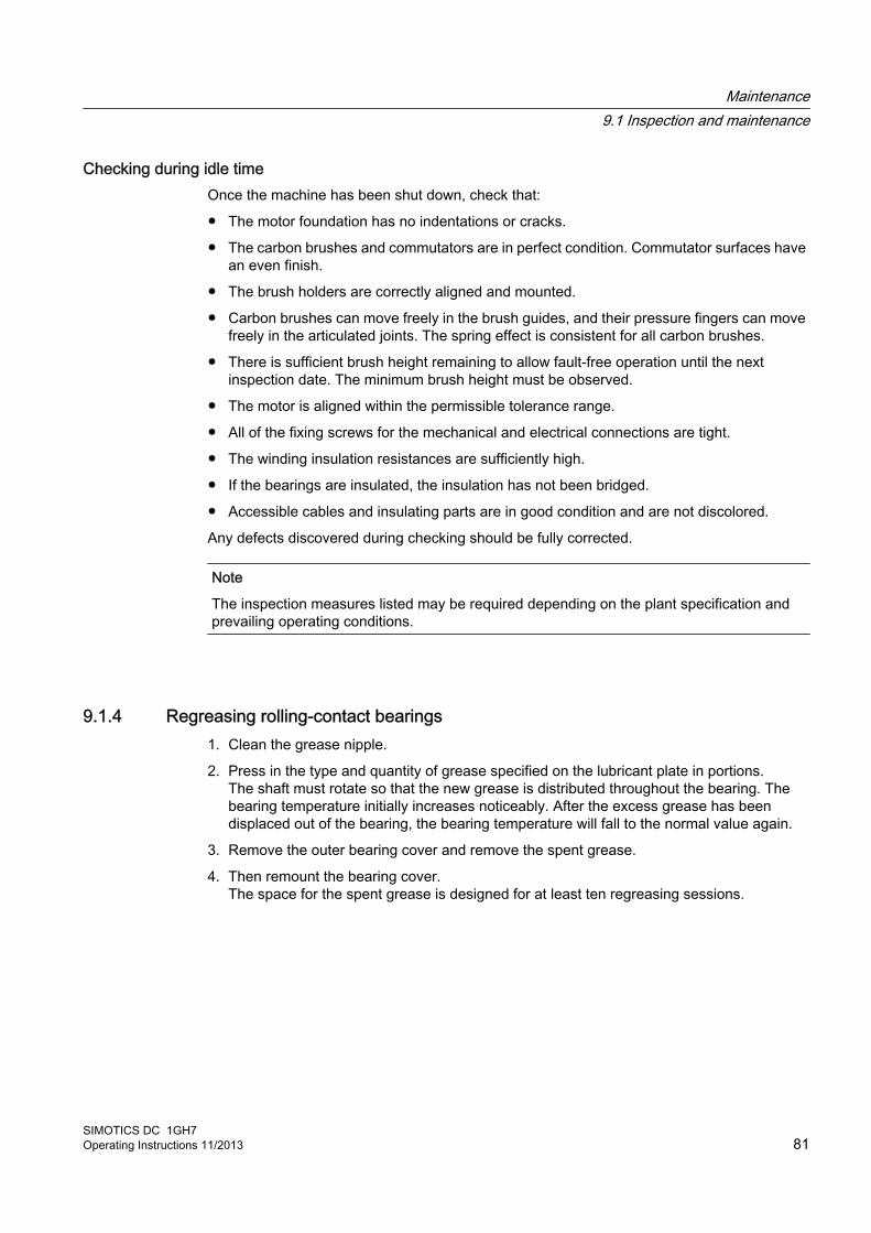
Checking during idle timeOnce the machine has been shut down, check that:
● The motor foundation has no indentations or cracks.
● The carbon brushes and commutators are in perfect condition. Commutator surfaces have an even finish.
● The brush holders are correctly aligned and mounted.
● Carbon brushes can move freely in the brush guides, and their pressure fingers can move freely in the articulated joints. The spring effect is consistent for all carbon brushes.
● There is sufficient brush height remaining to allow fault-free operation until the next inspection date. The minimum brush height must be observed.
● The motor is aligned within the permissible tolerance range.
● All of the fixing screws for the mechanical and electrical connections are tight.
● The winding insulation resistances are sufficiently high.
● If the bearings are insulated, the insulation has not been bridged.
● Accessible cables and insulating parts are in good condition and are not discolored.
Any defects discovered during checking should be fully corrected.
Note
The inspection measures listed may be required depending on the plant specification and prevailing operating conditions.
9.1.4 Regreasing rolling-contact bearings1. Clean the grease nipple.
2. Press in the type and quantity of grease specified on the lubricant plate in portions.The shaft must rotate so that the new grease is distributed throughout the bearing. The bearing temperature initially increases noticeably. After the excess grease has been displaced out of the bearing, the bearing temperature will fall to the normal value again.
3. Remove the outer bearing cover and remove the spent grease.
4. Then remount the bearing cover.The space for the spent grease is designed for at least ten regreasing sessions.
Maintenance9.1 Inspection and maintenance
SIMOTICS DC 1GH7Operating Instructions 11/2013 81
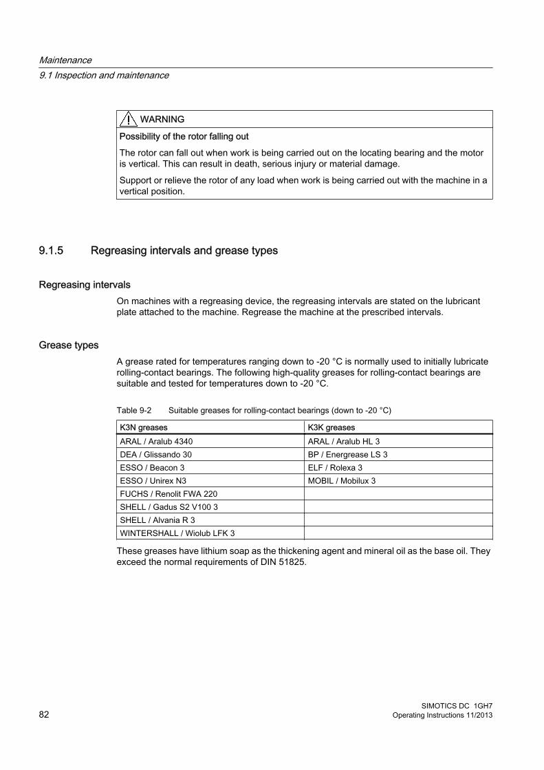
WARNING
Possibility of the rotor falling out
The rotor can fall out when work is being carried out on the locating bearing and the motor is vertical. This can result in death, serious injury or material damage.
Support or relieve the rotor of any load when work is being carried out with the machine in a vertical position.
9.1.5 Regreasing intervals and grease types
Regreasing intervalsOn machines with a regreasing device, the regreasing intervals are stated on the lubricant plate attached to the machine. Regrease the machine at the prescribed intervals.
Grease typesA grease rated for temperatures ranging down to -20 °C is normally used to initially lubricate rolling-contact bearings. The following high-quality greases for rolling-contact bearings are suitable and tested for temperatures down to -20 °C.
Table 9-2 Suitable greases for rolling-contact bearings (down to -20 °C)
K3N greases K3K greasesARAL / Aralub 4340 ARAL / Aralub HL 3DEA / Glissando 30 BP / Energrease LS 3ESSO / Beacon 3 ELF / Rolexa 3ESSO / Unirex N3 MOBIL / Mobilux 3FUCHS / Renolit FWA 220 SHELL / Gadus S2 V100 3 SHELL / Alvania R 3 WINTERSHALL / Wiolub LFK 3
These greases have lithium soap as the thickening agent and mineral oil as the base oil. They exceed the normal requirements of DIN 51825.
Maintenance9.1 Inspection and maintenance
SIMOTICS DC 1GH782 Operating Instructions 11/2013
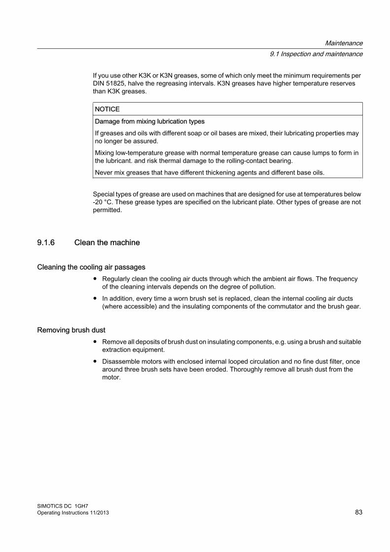
If you use other K3K or K3N greases, some of which only meet the minimum requirements per DIN 51825, halve the regreasing intervals. K3N greases have higher temperature reserves than K3K greases.
NOTICE
Damage from mixing lubrication types
If greases and oils with different soap or oil bases are mixed, their lubricating properties may no longer be assured.
Mixing low-temperature grease with normal temperature grease can cause lumps to form in the lubricant. and risk thermal damage to the rolling-contact bearing.
Never mix greases that have different thickening agents and different base oils.
Special types of grease are used on machines that are designed for use at temperatures below -20 °C. These grease types are specified on the lubricant plate. Other types of grease are not permitted.
9.1.6 Clean the machine
Cleaning the cooling air passages● Regularly clean the cooling air ducts through which the ambient air flows. The frequency
of the cleaning intervals depends on the degree of pollution.
● In addition, every time a worn brush set is replaced, clean the internal cooling air ducts (where accessible) and the insulating components of the commutator and the brush gear.
Removing brush dust● Remove all deposits of brush dust on insulating components, e.g. using a brush and suitable
extraction equipment.
● Disassemble motors with enclosed internal looped circulation and no fine dust filter, once around three brush sets have been eroded. Thoroughly remove all brush dust from the motor.
Maintenance9.1 Inspection and maintenance
SIMOTICS DC 1GH7Operating Instructions 11/2013 83

● When brush rockers are cleaned, care must be taken not to damage the trip mechanism on motors with brush-height monitoring.
NoteDamage on the surface of the sound absorber elements
On external fans with sound absorbers, the surface of the absorber elements is pressure-sensitive. Air-pressure cleaning can damage this surface.● Air-pressure cleaning equipment should not be used directly on the sound absorber
elements. ● Carefully brush away any large deposits of dust which could be drawn in whole by the
air flow.
● Replace dirty cassette filters with new ones.
● After cleaning, check the insulation resistance.
9.1.7 Checking the carbon brushesIn normal operation, check regularly to ensure the carbon brushes are in good contact with the commutator and are moving freely in the brush guides.
Brush heightThe wear limit of carbon brushes is indicated by a line or by the lower edge of the manufacturer's name stamp.
On machines with a brush-height monitoring function, the shortest brush opens a microswitch when the brush has worn to at least 2 mm higher than the minimum brush height. Under normal operating conditions, the machine can then continue to operate for a further 500 to 1,000 hours.
NOTICE
Worn carbon brushes
If the motor is operated with worn carbon brushes, this can lead to material damage.
Replace used carbon brushes immediately.
Maintenance9.1 Inspection and maintenance
SIMOTICS DC 1GH784 Operating Instructions 11/2013

9.1.8 Replacing the carbon brushes
Removing worn carbon brushesAll brush holders can usually be accessed by opening the cover/louvered cover on the bearing shield at the non-drive end.
1. Disconnect the cables from the brush rocker if necessary.
2. After you have loosened the lock screws accessible from the inside, turn the brush rocker into an easily accessible position.
CAUTION
Open pressure levers can spring back
Open pressure levers on brush holders can spring back, causing minor injuries. When working on a brush holder, make sure that the holder finger does not snap shut.
Mounting new carbon brushes1. When you replace carbon brushes, make sure that you replace them with exactly the same
type and model.You will find the brush type and manufacturer's mark on the upper part of carbon brushes.
2. Prepare a strip of emery cloth that is not too coarse. The following dimensions are required: width equal to the commutator contact length and length equal to the commutator circumference.
3. Fix the strip of emery cloth to the commutator using double-sided adhesive tape.
4. Insert the new carbon brushes.
5. Manually, slowly turn the commutator in the correct direction of rotation. In exceptional cases, pull the emery cloth through under the brushes by hand until the entire brush surface is resting in contact with the commutator.Avoid damaging the brush edges when grinding in the new carbon brushes.
6. Carefully remove the emery cloth and any adhesive-tape residue left behind on the commutator surface.
7. Thoroughly suck (or blow) out the brush dust which has settled.
8. Check that all brush holders are correctly closed.
Maintenance9.1 Inspection and maintenance
SIMOTICS DC 1GH7Operating Instructions 11/2013 85
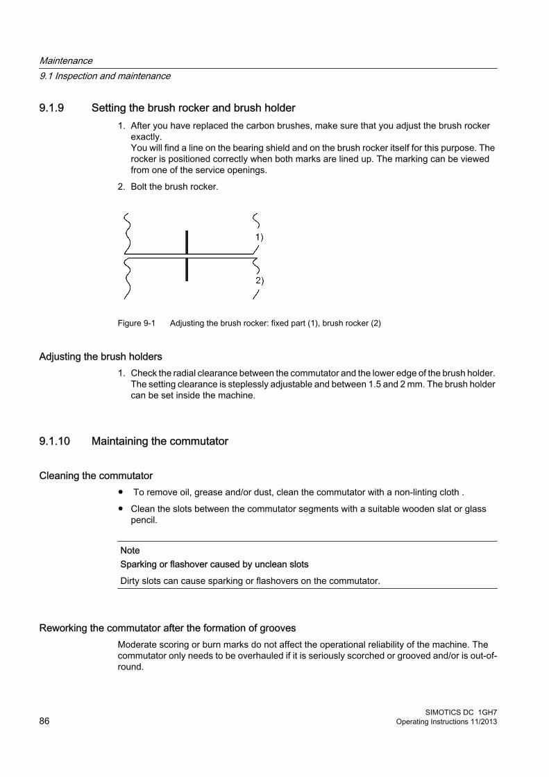
9.1.9 Setting the brush rocker and brush holder1. After you have replaced the carbon brushes, make sure that you adjust the brush rocker
exactly.You will find a line on the bearing shield and on the brush rocker itself for this purpose. The rocker is positioned correctly when both marks are lined up. The marking can be viewed from one of the service openings.
2. Bolt the brush rocker.
Figure 9-1 Adjusting the brush rocker: fixed part (1), brush rocker (2)
Adjusting the brush holders1. Check the radial clearance between the commutator and the lower edge of the brush holder.
The setting clearance is steplessly adjustable and between 1.5 and 2 mm. The brush holder can be set inside the machine.
9.1.10 Maintaining the commutator
Cleaning the commutator● To remove oil, grease and/or dust, clean the commutator with a non-linting cloth .
● Clean the slots between the commutator segments with a suitable wooden slat or glass pencil.
NoteSparking or flashover caused by unclean slots
Dirty slots can cause sparking or flashovers on the commutator.
Reworking the commutator after the formation of groovesModerate scoring or burn marks do not affect the operational reliability of the machine. The commutator only needs to be overhauled if it is seriously scorched or grooved and/or is out-of-round.
Maintenance9.1 Inspection and maintenance
SIMOTICS DC 1GH786 Operating Instructions 11/2013
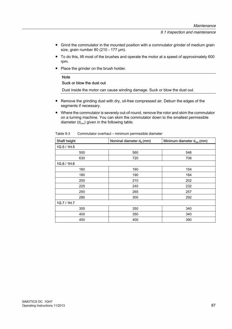
● Grind the commutator in the mounted position with a commutator grinder of medium grain size, grain number 80 (210 - 177 μm).
● To do this, lift most of the brushes and operate the motor at a speed of approximately 600 rpm.
● Place the grinder on the brush holder.
NoteSuck or blow the dust out
Dust inside the motor can cause winding damage. Suck or blow the dust out.
● Remove the grinding dust with dry, oil-free compressed air. Deburr the edges of the segments if necessary.
● Where the commutator is severely out-of-round, remove the rotor and skim the commutator on a turning machine. You can skim the commutator down to the smallest permissible diameter (dmin) given in the following table.
Table 9-3 Commutator overhaul – minimum permissible diameter
Shaft height Nominal diameter dN (mm) Minimum diameter dmin (mm)1G.5 / 1H.5
500 560 546630 720 706
1G.6 / 1H.6160 160 154180 190 184200 210 202225 240 232250 265 257280 300 292
1G.7 / 1H.7355 350 340400 350 340450 400 390
Maintenance9.1 Inspection and maintenance
SIMOTICS DC 1GH7Operating Instructions 11/2013 87
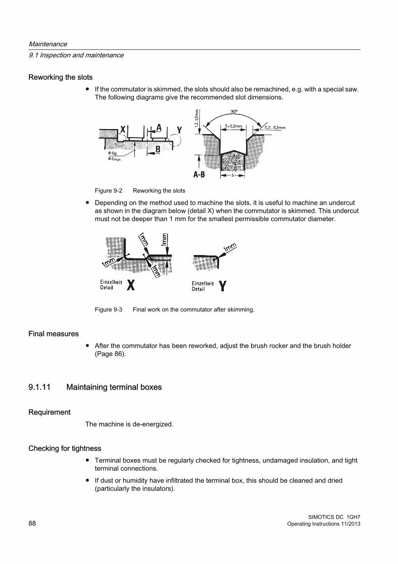
Reworking the slots● If the commutator is skimmed, the slots should also be remachined, e.g. with a special saw.
The following diagrams give the recommended slot dimensions.
Figure 9-2 Reworking the slots
● Depending on the method used to machine the slots, it is useful to machine an undercut as shown in the diagram below (detail X) when the commutator is skimmed. This undercut must not be deeper than 1 mm for the smallest permissible commutator diameter.
Figure 9-3 Final work on the commutator after skimming.
Final measures● After the commutator has been reworked, adjust the brush rocker and the brush holder
(Page 86).
9.1.11 Maintaining terminal boxes
RequirementThe machine is de-energized.
Checking for tightness● Terminal boxes must be regularly checked for tightness, undamaged insulation, and tight
terminal connections.
● If dust or humidity have infiltrated the terminal box, this should be cleaned and dried (particularly the insulators).
Maintenance9.1 Inspection and maintenance
SIMOTICS DC 1GH788 Operating Instructions 11/2013
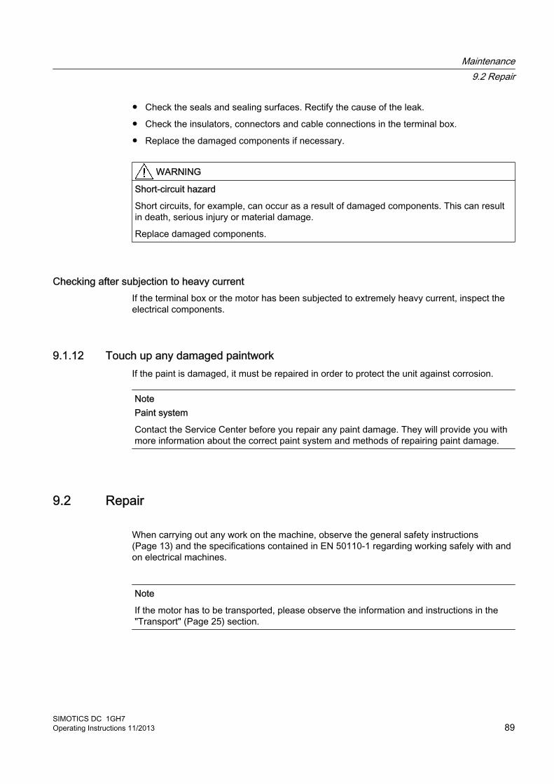
● Check the seals and sealing surfaces. Rectify the cause of the leak.
● Check the insulators, connectors and cable connections in the terminal box.
● Replace the damaged components if necessary.
WARNING
Short-circuit hazard
Short circuits, for example, can occur as a result of damaged components. This can result in death, serious injury or material damage.
Replace damaged components.
Checking after subjection to heavy currentIf the terminal box or the motor has been subjected to extremely heavy current, inspect the electrical components.
9.1.12 Touch up any damaged paintworkIf the paint is damaged, it must be repaired in order to protect the unit against corrosion.
NotePaint system
Contact the Service Center before you repair any paint damage. They will provide you with more information about the correct paint system and methods of repairing paint damage.
9.2 Repair
When carrying out any work on the machine, observe the general safety instructions (Page 13) and the specifications contained in EN 50110‑1 regarding working safely with and on electrical machines.
Note
If the motor has to be transported, please observe the information and instructions in the "Transport" (Page 25) section.
Maintenance9.2 Repair
SIMOTICS DC 1GH7Operating Instructions 11/2013 89

9.2.1 Prepare servicing work● The drawings and parts lists do not contain any detailed information about the type and
dimensions of fixing elements and components. For this reason, you should establish this information when dismantling them and make a note of it for the purpose of reassembly.
● Document the type, dimensions and arrangement of the parts so that you will be able to reassemble the machine to its original state.
● Use suitable tools to disassemble the machine.
● Take measures to prevent parts from dropping down before you dismantle them, e.g. by replacing fastening elements with extra-long screws, threaded bolts or similar. This ensures that the part is supported after it is pulled off.
● The centerings in the shaft extensions have reset threads. Use lifting gear which is suitable for the rotor weight and direction of loading.
WARNING
Rotor can fall down
Eyebolts in accordance with DIN 580 are unsuitable for suspending the rotor. The rotor can fall off. This can result in death, serious injury or material damage.
Use lifting gear which is suitable for the rotor weight and direction of loading.
WARNING
Machine damage caused by improper repair work
Improper servicing work can damage the machine. This can cause damages and/or faults which can result in eventual or immediate death, serious injury, or property damage.● Properly assemble or disassemble the machine.● Use only suitable tools and equipment.● Immediately replace damaged components.● Contact the Service Center, if necessary.
WARNING
Rotor can fall out
If the motor is in a vertical position, the rotor can fall out while work is being performed on the locating bearing. This can result in death, serious injury or damage.● Support or unload the rotor when carrying out work with the machine in a vertical position.
Maintenance9.2 Repair
SIMOTICS DC 1GH790 Operating Instructions 11/2013

Removing the machine
Note
Only qualified personnel is permitted to perform maintenance work. Contact the Service Center (Page 117), if necessary.
● If you have to disassemble the motor, disconnect the connecting leads from the terminals and the entry plate from the terminal box casing. In this way, the relative positions of the cables will remain correct. Effective sealing of the cables in the cable entries is retained.
● Check the identification of the connecting cables. If the identifiers are not correct, correct the identification.
WiringThe terminal diagram shows only the mains connection conditions without including any compensation and auxiliary windings.
Mark internal connections for identification before disconnecting them for maintenance work.
9.2.2 Disassembling the machine
Attaching a rotorThe centerings in the shaft extensions have reset threads. Eyebolts conforming to DIN 580 are not suitable for vertical rotor attachment as only a small number of thread grooves are used.
● Depending on the weight of the rotor and the direction of the load, other suitable elements (with a length of engagement > 0.8 x thread diameter) should be used.
Disassembling the machine1. The drawings and parts lists do not contain any detailed information about the type and
dimensions of fixing elements. Therefore, make sure their assignment is correct before disassembly. Mark their assignment with identification for assembly.
2. Before disassembly, ensure that the housing and bearing shield are marked at a corresponding point on the non-drive end. Use a suitable means of identification, e.g. a flat chipping mark. The correct position of the brush rocker in relation to the bearing shield and stator frame is important for setting the neutral zone.
3. Ensure correct assignment and orientation of the parts: bearings, sealing rings, compression springs, spring washers, covers with different centering lengths.
4. When removing the DE bearing shield, make sure that the windings that project from the stator frame do not become damaged.
Maintenance9.2 Repair
SIMOTICS DC 1GH7Operating Instructions 11/2013 91
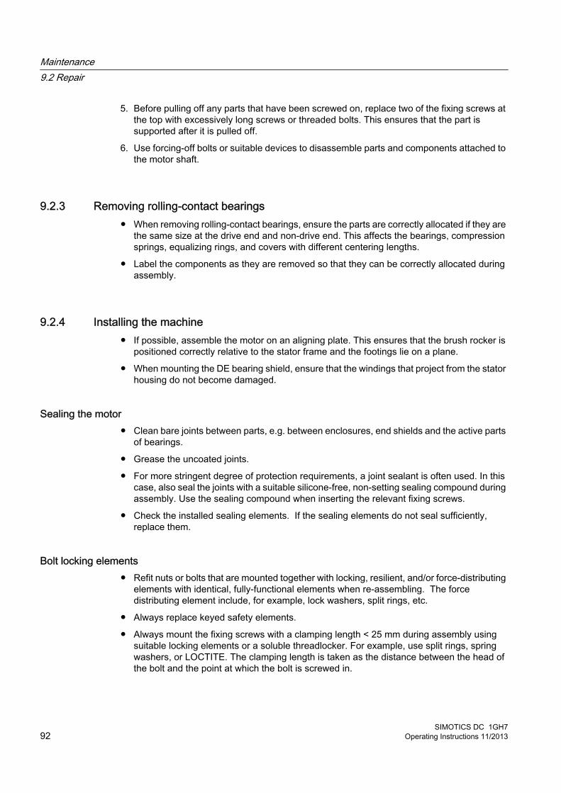
5. Before pulling off any parts that have been screwed on, replace two of the fixing screws at the top with excessively long screws or threaded bolts. This ensures that the part is supported after it is pulled off.
6. Use forcing-off bolts or suitable devices to disassemble parts and components attached to the motor shaft.
9.2.3 Removing rolling-contact bearings● When removing rolling-contact bearings, ensure the parts are correctly allocated if they are
the same size at the drive end and non-drive end. This affects the bearings, compression springs, equalizing rings, and covers with different centering lengths.
● Label the components as they are removed so that they can be correctly allocated during assembly.
9.2.4 Installing the machine● If possible, assemble the motor on an aligning plate. This ensures that the brush rocker is
positioned correctly relative to the stator frame and the footings lie on a plane.
● When mounting the DE bearing shield, ensure that the windings that project from the stator housing do not become damaged.
Sealing the motor ● Clean bare joints between parts, e.g. between enclosures, end shields and the active parts
of bearings.
● Grease the uncoated joints.
● For more stringent degree of protection requirements, a joint sealant is often used. In this case, also seal the joints with a suitable silicone-free, non-setting sealing compound during assembly. Use the sealing compound when inserting the relevant fixing screws.
● Check the installed sealing elements. If the sealing elements do not seal sufficiently, replace them.
Bolt locking elements● Refit nuts or bolts that are mounted together with locking, resilient, and/or force-distributing
elements with identical, fully-functional elements when re-assembling. The force distributing element include, for example, lock washers, split rings, etc.
● Always replace keyed safety elements.
● Always mount the fixing screws with a clamping length < 25 mm during assembly using suitable locking elements or a soluble threadlocker. For example, use split rings, spring washers, or LOCTITE. The clamping length is taken as the distance between the head of the bolt and the point at which the bolt is screwed in.
Maintenance9.2 Repair
SIMOTICS DC 1GH792 Operating Instructions 11/2013

9.2.5 Mounting the rolling-contact bearingsTake great care and pay attention to cleanliness when fitting and assembling the bearings.
Make sure that you use the correct components for the rolling-contact bearing type in question. For information about the rolling-contact bearings installed, please refer to the lubricant plate.
Mounting the rolling-contact bearings 1. Heat the ball bearings or cylindrical-roller bearing's inner rings in oil or air at a temperature
of 100 C.
2. Then push the ball bearings or the inner rings onto the shaft at the inner ring of the bearing, up to its shoulder. Avoid any heavy blows that might damage the bearing.
3. Fill the bearing to the top with the specified lubricating grease (Page 82).
4. Check that the existing sealing rings still perform their function. Replace the sealing rings if necessary.
Sealing the bearings● Before installing new felt rings in the bearing cover, soak them in hot, highly viscous oil at
approximately 100 °C, such as DIN 51517-C100 lubricating oil. They must be dimensioned such that the shaft can move freely, but is tightly enclosed by the rings.
● When installing external V-rings, the V-ring has reached the correct axial position when the end face of the bearing cover is flush with the outer edge of the V-ring. Use an appropriate auxiliary installation disk for this purpose.
● Check whether an additional sheet-metal protecting ring has been inserted in the bearing cover or bearing shield to protect the V-Ring. If so, pay attention to the following points during assembly:
– The ring has sufficient pretension.
– One of its two slots coincides with the corresponding water drainage slot provided at the bottom of the bearing cover seat or bearing shield seat.
● If rotary shaft seals without helical springs are installed, also install the replacement part without a spring.
Maintenance9.2 Repair
SIMOTICS DC 1GH7Operating Instructions 11/2013 93

Speed sensor ● If you are using a speed sensor with an inner V-ring on the outer bearing cover, the V-ring
must be positioned against the shoulder of the shaft journal.
9.2.6 Replacing the speed encoder
9.2.6.1 Speed sensor with conical hub
DisassemblyThe speed-sensor rotor with its conical hub either rests on, or is bolted to, the machine shaft journal.
NoteDamage to the speed sensor
The speed sensor can be damaged during motor disassembly. Remove the speed sensor before disassembling the motor.
1. Remove the cover of the speed sensor.
2. Unscrew the speed-sensor stator and move it away, axially. Take care with the brushes when doing this.
3. Unscrew the central M6 fixing screw from the speed-sensor rotor.
4. Insert a steel pin (4.8 x 24) into the threaded hole to support the forcing-off bolt.
5. Screw the M8 forcing-off bolt (minimum thread length 30 mm) into the threaded hole of the hub of the speed-sensor rotor, thus forcing the rotor off the conical base of the shaft journal.
6. The shaft journals or half-couplings mounted on or in the machine shaft extension must be dismantled and replaced if they are damaged.
– When replacing damaged parts, such as the tolerance ring, please ensure they are correctly arranged.
– Use removable LOCTITE and suitable tools to assemble parts.
7. Use a socket screw wrench to DIN 3113 (width between pivots 35 mm) to screw or unscrew the bolt-mounted shaft journal.
Table 9-4 Recommended torques for tightening the shaft journal
Thread size Torque [Nm]M16 20M20 30M24 40
Maintenance9.2 Repair
SIMOTICS DC 1GH794 Operating Instructions 11/2013
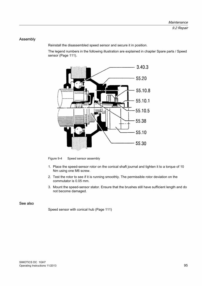
AssemblyReinstall the disassembled speed sensor and secure it in position.
The legend numbers in the following illustration are explained in chapter Spare parts / Speed sensor (Page 111).
Figure 9-4 Speed sensor assembly
1. Place the speed-sensor rotor on the conical shaft journal and tighten it to a torque of 10 Nm using one M6 screw.
2. Test the rotor to see if it is running smoothly. The permissible rotor deviation on the commutator is 0.05 mm.
3. Mount the speed-sensor stator. Ensure that the brushes still have sufficient length and do not become damaged.
See alsoSpeed sensor with conical hub (Page 111)
Maintenance9.2 Repair
SIMOTICS DC 1GH7Operating Instructions 11/2013 95
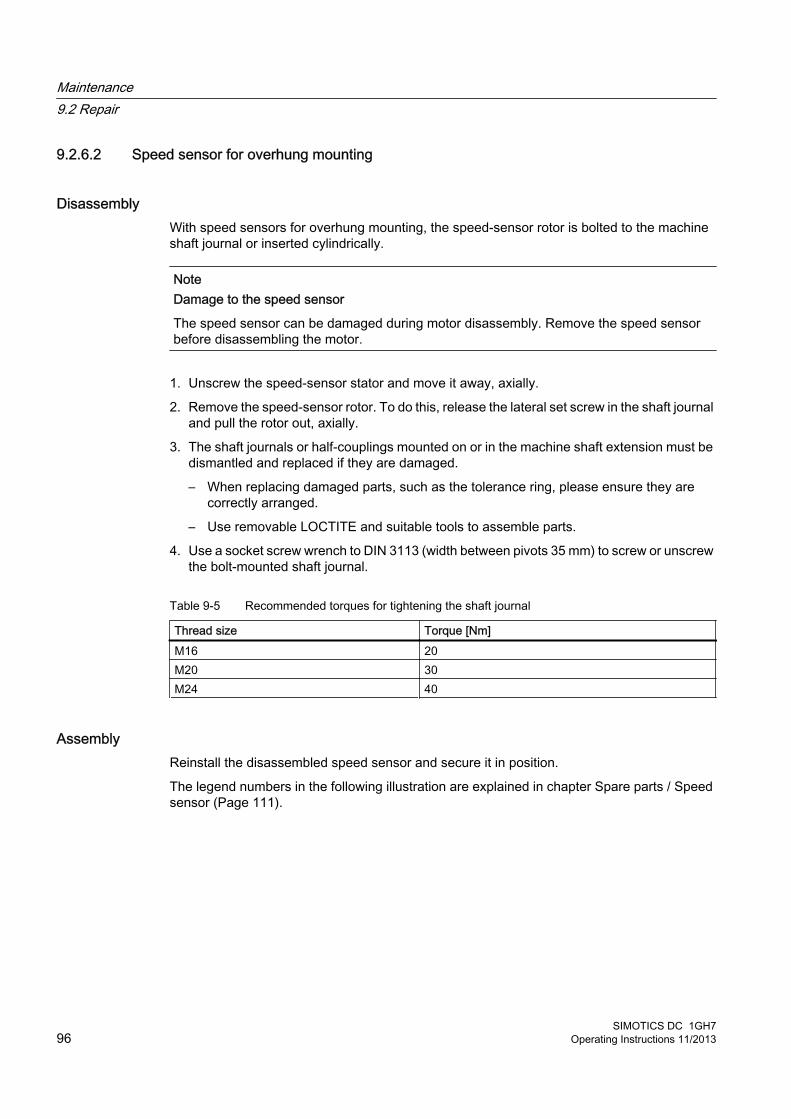
9.2.6.2 Speed sensor for overhung mounting
DisassemblyWith speed sensors for overhung mounting, the speed-sensor rotor is bolted to the machine shaft journal or inserted cylindrically.
NoteDamage to the speed sensor
The speed sensor can be damaged during motor disassembly. Remove the speed sensor before disassembling the motor.
1. Unscrew the speed-sensor stator and move it away, axially.
2. Remove the speed-sensor rotor. To do this, release the lateral set screw in the shaft journal and pull the rotor out, axially.
3. The shaft journals or half-couplings mounted on or in the machine shaft extension must be dismantled and replaced if they are damaged.
– When replacing damaged parts, such as the tolerance ring, please ensure they are correctly arranged.
– Use removable LOCTITE and suitable tools to assemble parts.
4. Use a socket screw wrench to DIN 3113 (width between pivots 35 mm) to screw or unscrew the bolt-mounted shaft journal.
Table 9-5 Recommended torques for tightening the shaft journal
Thread size Torque [Nm]M16 20M20 30M24 40
AssemblyReinstall the disassembled speed sensor and secure it in position.
The legend numbers in the following illustration are explained in chapter Spare parts / Speed sensor (Page 111).
Maintenance9.2 Repair
SIMOTICS DC 1GH796 Operating Instructions 11/2013
Figure 9-5 Speed sensor assembly
● Push the cylindrical shaft extension of the speed-sensor rotor as far as possible into the shaft journal and secure it with the lateral set screw (M4 x 6).
● Use removable LOCTITE and a tightening torque of 13 Nm to attach the set screw.
● Test the rotor to see if it is running smoothly. The permissible rotor deviation on the commutator is 0.2 mm.
● Mount the entire speed-sensor stator.
See alsoSpeed sensor for overhung mounting (Page 112)
9.2.6.3 Speed sensor for construction type IM B5
DisassemblyThe speed sensor is designed for mounting as for construction type IM B5. It is actuated by means of a jaw clutch (Rotex).
Maintenance9.2 Repair
SIMOTICS DC 1GH7Operating Instructions 11/2013 97

If a different design is used, the installation and operating instructions of the speed sensor manufacturer apply.
NoteDamage to the speed sensor
The speed sensor can be damaged during motor disassembly. Remove the speed sensor before disassembling the motor.
1. Unscrew the speed sensor completely and move it away, axially. This separates the half-couplings axially.
2. The shaft journals or half-couplings mounted on or in the machine shaft extension must be dismantled and replaced if they are damaged.
– When replacing damaged parts, such as the tolerance ring, please ensure they are correctly arranged.
– Use removable LOCTITE and suitable tools to assemble parts.
3. Undo or tighten the bolt-mounted half-coupling on the hexagonal recess (A/F 8 mm).
Table 9-6 Recommended torques for tightening the half-coupling
Thread size Torque [Nm]M16 20M20 30M24 40
AssemblyReinstall the disassembled speed sensor and secure it in position. If a different design is used, the installation and operating instructions of the speed sensor manufacturer apply.
The legend numbers in the following illustration are explained in chapter Spare parts / Speed sensor (Page 111).
Maintenance9.2 Repair
SIMOTICS DC 1GH798 Operating Instructions 11/2013
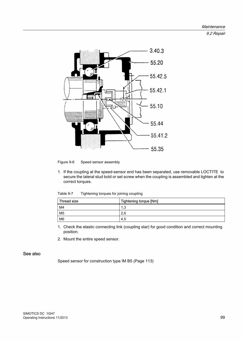
Figure 9-6 Speed sensor assembly
1. If the coupling at the speed-sensor end has been separated, use removable LOCTITE to secure the lateral stud bold or set screw when the coupling is assembled and tighten at the correct torques.
Table 9-7 Tightening torques for joining coupling
Thread size Tightening torque [Nm]M4 1,3M5 2,6M6 4,5
1. Check the elastic connecting link (coupling star) for good condition and correct mounting position.
2. Mount the entire speed sensor.
See alsoSpeed sensor for construction type IM B5 (Page 113)
Maintenance9.2 Repair
SIMOTICS DC 1GH7Operating Instructions 11/2013 99

Maintenance9.2 Repair
SIMOTICS DC 1GH7100 Operating Instructions 11/2013
Spare Parts 1010.1 Ordering data
In addition to the exact part designation, please specify the machine type and serial number in all orders for spare parts. Ensure that the spare part designation matches that on the spare parts list and make sure you use the appropriate part number as well.
Example● Bearing shield, drive end (Part 5.00)
● Machine type
● Serial number
The machine type and serial number can be found on the rating plate. The serial number is also stamped on the end face of the shaft extension at the drive end.
Note
The graphical representations in this chapter show schematic diagrams of the basic versions. They are used for spare parts definitions. The supplied version may differ in details from these representations.
Carbon brushesThe order number for carbon brushes and / or the brush designation is specified on the rating plate. You will also find the brush type and manufacturer's mark on the upper part of the brush.
Terminal boxIf several terminal boxes are mounted on the machine, please also indicate the type designation of the terminal box in addition to details of part designation and part number according to the legend, as well as type and serial number of the motor when ordering spare parts.
Example● Terminal box type
● Terminal box cover (part 20.30 )
● Serial number of the motor
● Machine type
SIMOTICS DC 1GH7Operating Instructions 11/2013 101
Rolling-contact bearingsWhen ordering roller bearings, in addition to the bearing identification code, the supplementary specifying code is also necessary for the bearing version. Both of these codes are stamped on the lubricant plate and specified in the motor documentation, or can also be taken from the installed bearings.
If roller-contact bearings with an insulated design are installed, use roller bearings of the same type as spare parts. This will prevent any bearing damage being caused by bearing currents.
10.2 Ordering spare parts via the InternetSpare parts can be ordered online from the spare parts service "Spares on Web":
Spares on Web (https://b2b-extern.automation.siemens.com/spares_on_web).
You can use "Spares on Web" to determine the order numbers for motor spare parts quickly and easily.
A short description of how to use "Spares on Web" is available on the Internet.
Guide for Spares on Web (http://support.automation.siemens.com/WW/news/en/25248626).
10.3 Using commercially available spare partsYou can use commercially available, standard components, but ensure that they have the same construction type, dimensions, strength class etc.
Spare Parts10.3 Using commercially available spare parts
SIMOTICS DC 1GH7102 Operating Instructions 11/2013
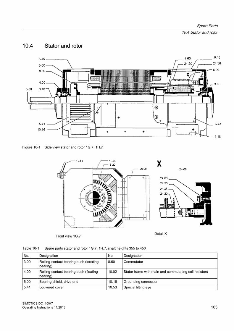
10.4 Stator and rotor
Figure 10-1 Side view stator and rotor 1G.7, 1H.7
Front view 1G.7Detail X
Table 10-1 Spare parts stator and rotor 1G.7, 1H.7, shaft heights 355 to 450
No. Designation No. Designation3.00 Rolling-contact bearing bush (locating
bearing)8.60 Commutator
4.00 Rolling-contact bearing bush (floating bearing)
10.02 Stator frame with main and commutating coil resistors
5.00 Bearing shield, drive end 10.16 Grounding connection5.41 Louvered cover 10.53 Special lifting eye
Spare Parts10.4 Stator and rotor
SIMOTICS DC 1GH7Operating Instructions 11/2013 103
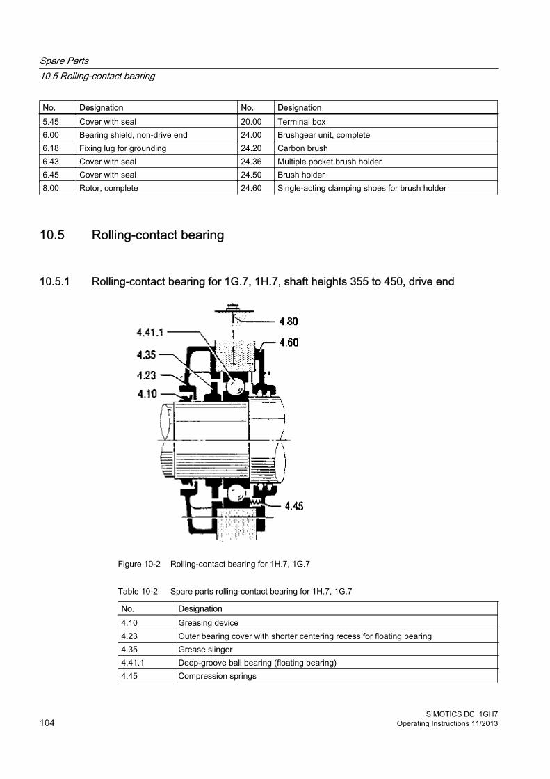
No. Designation No. Designation5.45 Cover with seal 20.00 Terminal box6.00 Bearing shield, non-drive end 24.00 Brushgear unit, complete6.18 Fixing lug for grounding 24.20 Carbon brush6.43 Cover with seal 24.36 Multiple pocket brush holder6.45 Cover with seal 24.50 Brush holder8.00 Rotor, complete 24.60 Single-acting clamping shoes for brush holder
10.5 Rolling-contact bearing
10.5.1 Rolling-contact bearing for 1G.7, 1H.7, shaft heights 355 to 450, drive end
Figure 10-2 Rolling-contact bearing for 1H.7, 1G.7
Table 10-2 Spare parts rolling-contact bearing for 1H.7, 1G.7
No. Designation4.10 Greasing device4.23 Outer bearing cover with shorter centering recess for floating bearing4.35 Grease slinger4.41.1 Deep-groove ball bearing (floating bearing)4.45 Compression springs
Spare Parts10.5 Rolling-contact bearing
SIMOTICS DC 1GH7104 Operating Instructions 11/2013

No. Designation4.60 Inner bearing cover with felt rings4.80 Grease nipple
Spare Parts10.5 Rolling-contact bearing
SIMOTICS DC 1GH7Operating Instructions 11/2013 105

10.5.2 Rolling-contact bearing for 1G.7, 1H.7, shaft heights 355 to 450 with one shaft extension, non-drive end
Figure 10-3 Rolling-contact bearing for 1G.7. 1H.7 with one shaft extension
Table 10-3 Spare parts rolling-contact bearing for 1G.7. 1H.7 with one shaft extension
No. Designation3.21 Outer bearing cover (end cover)3.30 Locking ring3.35 Grease slinger3.40.1 Deep-groove ball bearing (deep-groove ball bearing with sideplate, locating bearing)3.60 Inner bearing cover with felt rings3.80 Grease nipple
Spare Parts10.5 Rolling-contact bearing
SIMOTICS DC 1GH7106 Operating Instructions 11/2013
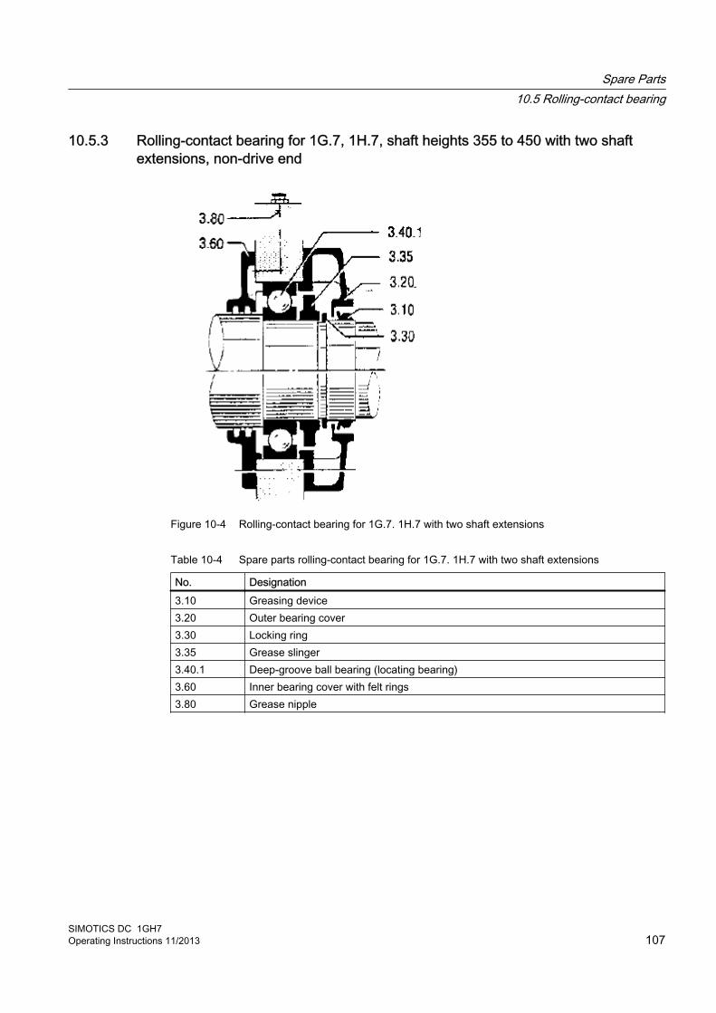
10.5.3 Rolling-contact bearing for 1G.7, 1H.7, shaft heights 355 to 450 with two shaft extensions, non-drive end
Figure 10-4 Rolling-contact bearing for 1G.7. 1H.7 with two shaft extensions
Table 10-4 Spare parts rolling-contact bearing for 1G.7. 1H.7 with two shaft extensions
No. Designation3.10 Greasing device3.20 Outer bearing cover3.30 Locking ring3.35 Grease slinger3.40.1 Deep-groove ball bearing (locating bearing)3.60 Inner bearing cover with felt rings3.80 Grease nipple
Spare Parts10.5 Rolling-contact bearing
SIMOTICS DC 1GH7Operating Instructions 11/2013 107
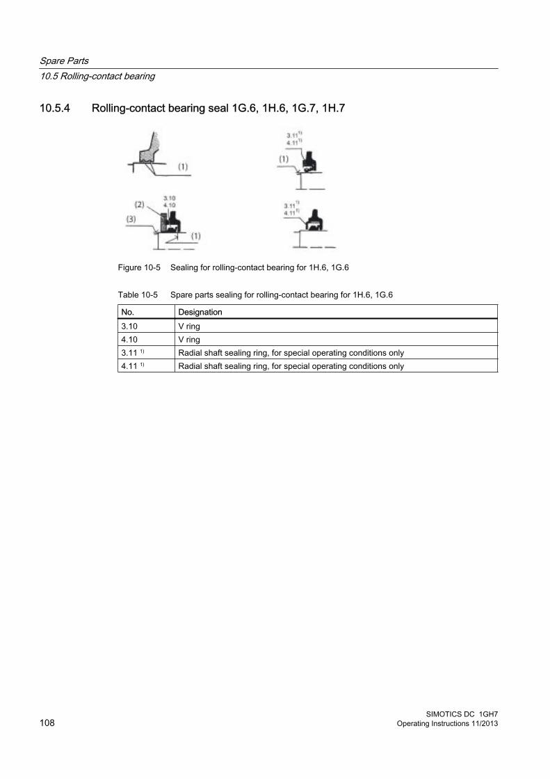
10.5.4 Rolling-contact bearing seal 1G.6, 1H.6, 1G.7, 1H.7
Figure 10-5 Sealing for rolling-contact bearing for 1H.6, 1G.6
Table 10-5 Spare parts sealing for rolling-contact bearing for 1H.6, 1G.6
No. Designation3.10 V ring4.10 V ring3.11 1) Radial shaft sealing ring, for special operating conditions only4.11 1) Radial shaft sealing ring, for special operating conditions only
Spare Parts10.5 Rolling-contact bearing
SIMOTICS DC 1GH7108 Operating Instructions 11/2013
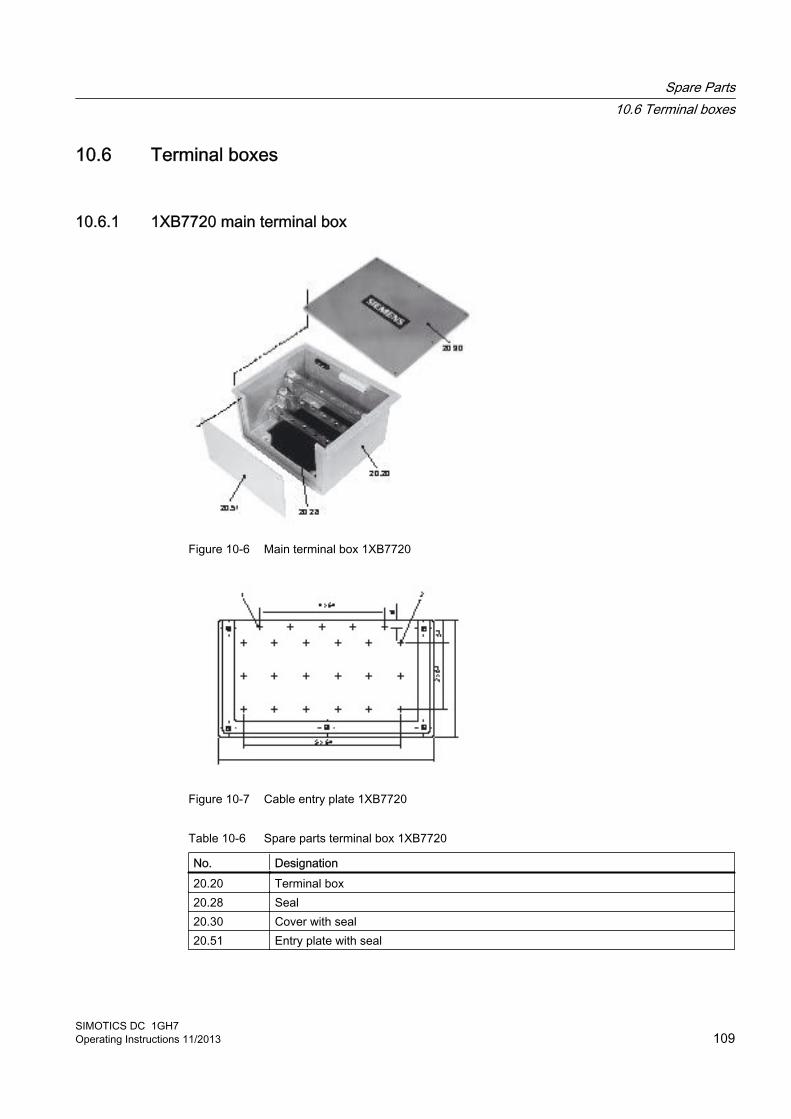
10.6 Terminal boxes
10.6.1 1XB7720 main terminal box
Figure 10-6 Main terminal box 1XB7720
Figure 10-7 Cable entry plate 1XB7720
Table 10-6 Spare parts terminal box 1XB7720
No. Designation20.20 Terminal box20.28 Seal20.30 Cover with seal20.51 Entry plate with seal
Spare Parts10.6 Terminal boxes
SIMOTICS DC 1GH7Operating Instructions 11/2013 109
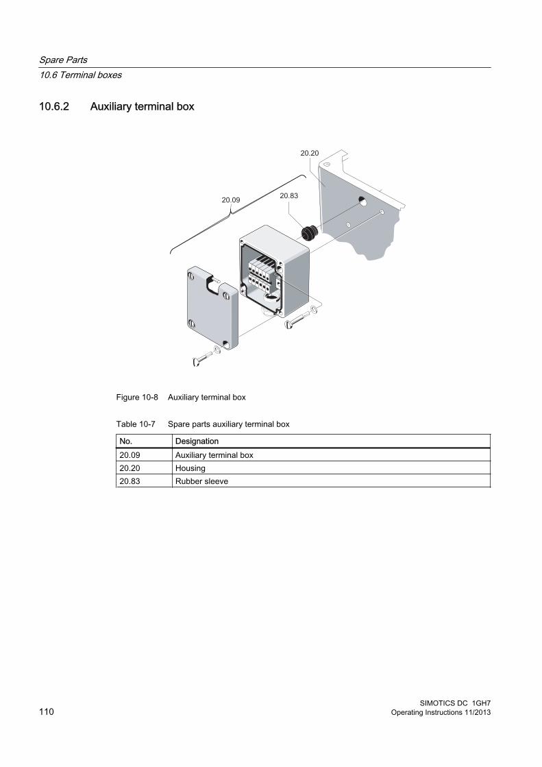
10.6.2 Auxiliary terminal box
Figure 10-8 Auxiliary terminal box
Table 10-7 Spare parts auxiliary terminal box
No. Designation20.09 Auxiliary terminal box20.20 Housing20.83 Rubber sleeve
Spare Parts10.6 Terminal boxes
SIMOTICS DC 1GH7110 Operating Instructions 11/2013
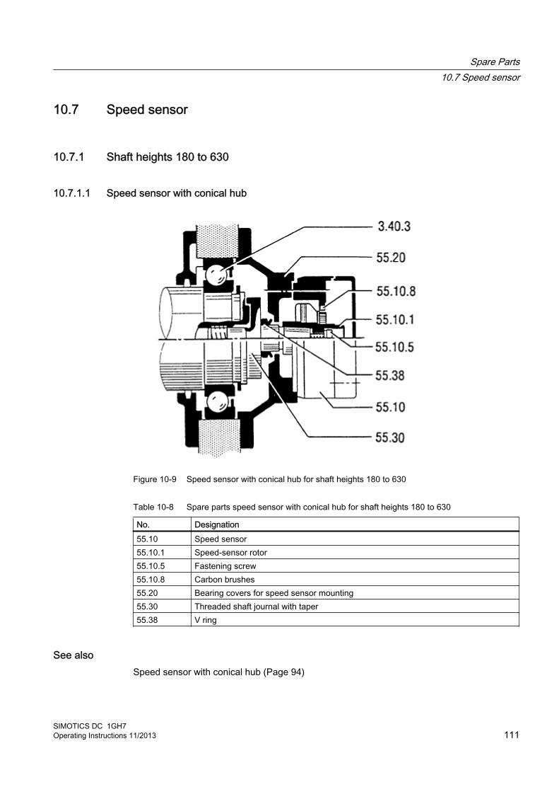
10.7 Speed sensor
10.7.1 Shaft heights 180 to 630
10.7.1.1 Speed sensor with conical hub
Figure 10-9 Speed sensor with conical hub for shaft heights 180 to 630
Table 10-8 Spare parts speed sensor with conical hub for shaft heights 180 to 630
No. Designation55.10 Speed sensor55.10.1 Speed-sensor rotor55.10.5 Fastening screw55.10.8 Carbon brushes55.20 Bearing covers for speed sensor mounting55.30 Threaded shaft journal with taper55.38 V ring
See alsoSpeed sensor with conical hub (Page 94)
Spare Parts10.7 Speed sensor
SIMOTICS DC 1GH7Operating Instructions 11/2013 111

10.7.1.2 Speed sensor for overhung mounting
Figure 10-10 Speed sensor for overhung mounting for shaft heights 180 to 630
Table 10-9 Spare parts speed sensor for overhung mounting for shaft heights 180 to 630
No. Designation55.10 Speed sensor55.10.1 Speed-sensor rotor55.20 Bearing covers for speed sensor mounting55.31 Threaded shaft journal with cylindrical hole55.31.5 Locking screw55.35 Tolerance ring
See alsoSpeed sensor for overhung mounting (Page 96)
Spare Parts10.7 Speed sensor
SIMOTICS DC 1GH7112 Operating Instructions 11/2013
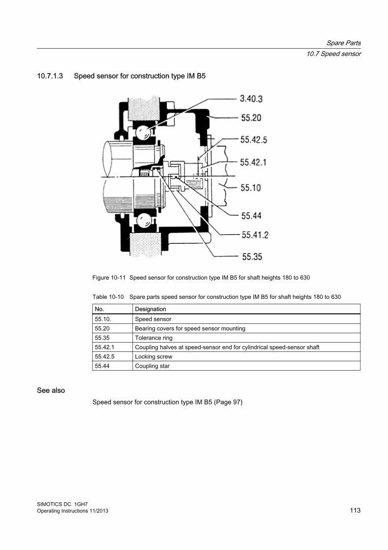
10.7.1.3 Speed sensor for construction type IM B5
Figure 10-11 Speed sensor for construction type IM B5 for shaft heights 180 to 630
Table 10-10 Spare parts speed sensor for construction type IM B5 for shaft heights 180 to 630
No. Designation55.10. Speed sensor55.20 Bearing covers for speed sensor mounting55.35 Tolerance ring55.42.1 Coupling halves at speed-sensor end for cylindrical speed-sensor shaft55.42.5 Locking screw55.44 Coupling star
See alsoSpeed sensor for construction type IM B5 (Page 97)
Spare Parts10.7 Speed sensor
SIMOTICS DC 1GH7Operating Instructions 11/2013 113

Spare Parts10.7 Speed sensor
SIMOTICS DC 1GH7114 Operating Instructions 11/2013

Disposal 1111.1 Introduction
Protecting the environment and preserving its resources are corporate goals of the highest priority for us. Our worldwide environmental management system to ISO 14001 ensures compliance with legislation and sets high standards in this regard. Environmentally friendly design, technical safety and health protection are always firm goals even at the product development stage.
Recommendations for the environmentally friendly disposal of the machine and its components are given in the following section. Be sure to comply with local disposal regulations.
11.2 National statutory regulations
NoteObserve national statutory regulations
When disposing of the machine or of waste that is created during the individual phases of the life cycle, please observe the statutory requirements that apply in the country of use.
11.3 Dismantling the machineDismantle the machine using the general procedures commonly used in mechanical engineering.
WARNING
Machine parts can fall
The machine is made up of heavy parts. These parts are liable to fall during dismantling. This can result in death, serious injury or material damage.
Before you release any machine parts, secure them so that they cannot fall.
11.4 Disposal of components
Components The machines consist mainly of steel and various proportions of copper and aluminum. Metals are generally considered to be unlimitedly recyclable.
SIMOTICS DC 1GH7Operating Instructions 11/2013 115

Sort the components for recycling according to whether they are:
● Iron and steel
● Aluminum
● Non-ferrous metal, e.g. windingsThe winding insulation is incinerated during copper recycling.
● Insulating materials
● Cables and wires
● Electronic waste
Process materials and chemicals Sort the process materials and chemicals for recycling according to whether they are for example:
● Oil
● Grease
● Cleaning substances and solvents
● Paint residues
● Anti-corrosion agent
● Coolant additives such as inhibitors, antifreeze or biocides
Dispose of the separated components according to local regulations or via a specialist disposal company. The same applies for cloths and cleaning substances which have been used while working on the machine.
Packaging material● If necessary, contact a suitable specialist disposal company.
● Wooden packaging for sea transport consists of impregnated wood. Observe the local regulations.
● The foil used for water-proof packaging is an aluminum composite foil. It can be recycled thermally. Dirty foil must be disposed of via waste incineration.
Disposal11.4 Disposal of components
SIMOTICS DC 1GH7116 Operating Instructions 11/2013

Service and Support AA.1 Siemens Industry Online Support
Details regarding the design of this electrical machine and the permissible operating conditions are described in these instructions.
On-site service and spare parts If you wish to request local service or order spare parts, please contact your local Siemens sales office. This office will contact the responsible service center on your behalf.
Technical queries or additional information If you have any technical queries or you require additional information, please contact the Siemens Service Center.
Please have the following machine data ready:
● Machine type
● Machine number
You can find this data on the rating plate of the machine.
Contact at Central Technical Support for our customers in Germany
+49 911 895 7222+49 911 895 7223 [email protected] (mailto:[email protected])
Outside Germany, you can find your contact partners here:
http://support.automation.siemens.com/WW/view/de/16604999.
You can also call the following numbers directly during local working hours to reach a contact partner who speaks the corresponding national language.
Americas
+1 423 262 5710+1 423 262 [email protected]
SIMOTICS DC 1GH7Operating Instructions 11/2013 117
Asia/Pacific
+86 10 6475 7575+86 10 6474 [email protected]
A.2 Reduction of hazardous substances
"Reduction of hazardous substances" Based of the latest technology, we are replacing environmentally hazardous materials with non-hazardous materials. In doing so, safety in operation and handling will take priority at all times.
Service and SupportA.2 Reduction of hazardous substances
SIMOTICS DC 1GH7118 Operating Instructions 11/2013
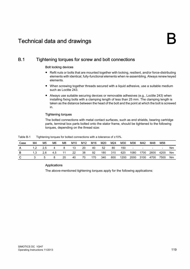
Technical data and drawings BB.1 Tightening torques for screw and bolt connections
Bolt locking devices ● Refit nuts or bolts that are mounted together with locking, resilient, and/or force-distributing
elements with identical, fully-functional elements when re-assembling. Always renew keyed elements.
● When screwing together threads secured with a liquid adhesive, use a suitable medium such as Loctite 243.
● Always use suitable securing devices or removable adhesives (e.g., Loctite 243) when installing fixing bolts with a clamping length of less than 25 mm. The clamping length is taken as the distance between the head of the bolt and the point at which the bolt is screwed in.
Tightening torques The bolted connections with metal contact surfaces, such as end shields, bearing cartridge parts, terminal box parts bolted onto the stator frame, should be tightened to the following torques, depending on the thread size:
Table B-1 Tightening torques for bolted connections with a tolerance of ±10%.
Case M4 M5 M6 M8 M10 M12 M16 M20 M24 M30 M36 M42 M48 M56 A 1,2 2,5 4 8 13 20 40 52 80 150 - - - - NmB 1,3 2,6 4,5 11 22 38 92 180 310 620 1080 1700 2600 4200 NmC 3 5 8 20 40 70 170 340 600 1200 2000 3100 4700 7500 Nm
ApplicationsThe above-mentioned tightening torques apply for the following applications:
SIMOTICS DC 1GH7Operating Instructions 11/2013 119
● Case AApplies to electrical connections in which the permissible torque is normally limited by the bolt materials and/or the current carrying capacity of the insulators, with the exception of the busbar connections in case B.
● Case BApplies to bolts screwed into components made from lower-strength materials (e. g. aluminum) and to bolts of strength class 8.8 to ISO 898-1.
● Case CApplies to bolts of strength class 8.8 or A4-70 to ISO 898-1, but only to bolts screwed into components made from higher-strength materials (e. g. gray cast iron, steel or cast steel).
NoteNon-standard tightening torques
Different tightening torques for electrical connections and bolted connections for parts with flat seals or insulating parts are specified in the relevant sections and drawings.
Technical data and drawingsB.1 Tightening torques for screw and bolt connections
SIMOTICS DC 1GH7120 Operating Instructions 11/2013

Quality documents CC.1 EC Declaration of Conformity 2006/95/EC
SIMOTICS DC 1GH7Operating Instructions 11/2013 121
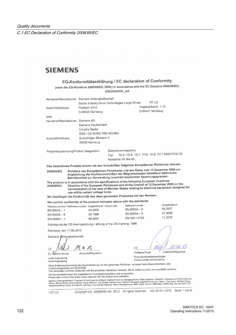
Quality documentsC.1 EC Declaration of Conformity 2006/95/EC
SIMOTICS DC 1GH7122 Operating Instructions 11/2013

I DT LD Copyright ( ) SIEMENS AG 2012 All rights reserved VQ 1013-1-1210 Seite 2 von 8
Englisch EC declaration of Conformity (in accordance with the EC Directive 2006/95/EC)
Manufacturer: Siemens AG Sector Industry Drive Technologies Large Drives, Vogelweiherstr. 1-15, D-90441 Nürnberg
The product is in accordance with the specifications of the following European directives. 2006/95/EC Directive of the European Parliament and of the Council of 12 December 2006 on the
harmonisation of the laws of Member States relating to electrical equipment designed for use within certain voltage limits
We confirm conformity of the product indicated above with the standards: see page 1
Affixing of the CE-marking: 1996
This declaration confirms conformity with the guidelines mentioned. However, this is neither a quality nor a durability warranty. Please take notice of the safety notes supplied with the product documentation. Französisch Déclaration CE de conformité (selon la directive 2006/95/CE )
Constructeur: Siemens AG Sector Industry Drive Technologies Large Drives, Vogelweiherstr. 1-15, D-90441 Nürnberg
Le produit sus-mentionné est conforme aux prescriptions des directives européennes suivantes : 2006/95/CE Directive du Parlement européen et du Conseil du 12 décembre 2006 concernant le rapprochement des législations des États membres relatives au matériel électrique destiné à être employé dans certaines limites de tension. Nous certifions la conformité du produit mentionné ci-dessus avec les normes: page 1
Apposition du marquage « CE »: 1996
Ce certificat atteste la conformité aux directives mentionnées, mais ne tient pas lieu de garantie de qualité ni de longévité. Respecter les consignes de sécurité figurant dans la documentation produit fournie. Spanisch Declaración de conformidad CE (según la Directiva2006/95/CE)
Fabricante: Siemens AG Sector Industry Drive Technologies Large Drives, Vogelweiherstr. 1-15, D-90441 Nürnberg
El producto arriba mencionado cumple con lo especificado en las Directivas Europeas siguientes: 2006/95/CE Directiva del Parlamento Europeo y del Consejo, de 12 de diciembre de 2006, relativa a la aproximación de las legislaciones de los Estados sobre el material eléctrico destinado a utilizarse con determinados límites de tensión. Confirmamos que el producto especificado cumple las siguientes normas: véase pagina 1
Colocación de la marca "CE": 1996
Esta declaración certifica el cumplimiento de las directivas mencionadas pero no garantiza las características ni la durabilidad. Deben observarse las consignas de seguridad de la documentación de producto suministrada.
Quality documentsC.1 EC Declaration of Conformity 2006/95/EC
SIMOTICS DC 1GH7Operating Instructions 11/2013 123

I DT LD Copyright ( ) SIEMENS AG 2012 All rights reserved VQ 1013-1-1210 Seite 3 von 8
Italienisch Dichiarazione di conformità CE (secondo la Direttiva CE 2006/95/CE)
Costruttore: Siemens AG Sector Industry Drive Technologies Large Drives, Vogelweiherstr. 1-15, D-90441 Nürnberg
Il prodotto indicato soddisfa le norme delle seguenti Direttive Europee. 2006/95/CE Direttiva del Parlamento Europeo e del Consiglio del 12 dicembre 2006 concernente il ravvicinamento delle legislazioni degli Stati membri relative al materiale elettrico destinato ad essere adoperato entro taluni limiti di tensione Si certifica la conformità del prodotto denominato alle norme seguenti: vedi pagina 1
Apposizione del marchio CE : 1996 Questa dichiarazione certifica la conformità con le direttive citate, non costituisce però alcuna garanzia di caratteristiche di prodotto oppure di durata. Le avvertenze di sicurezza riportate nella documentazione di prodotto allegata devono essere rispettate. Schwedisch: EG-konformitetsförklaring (enligt EG-direktiv 2006/95/EG)
Tillverkare: Siemens AG Sector Industry Drive Technologies Large Drives, Vogelweiherstr. 1-15, D-90441 Nürnberg
Den märkta produkten överensstämmer med föreskrifterna i följande europeiska direktiv: 2006/95/EG Europaparlamentets och rådets direktiv av den 26 December 2006 om harmonisering av medlemsstaternas lagstiftning om elektrisk utrustning avsedd för användning inom vissa spänningsgränser. Vi bekräftar ovan angivna produkts överensstämmelse med standarderna: 1
Placering av CE-märkning: 1996
Denna förklaring garanterar överensstämmelse med nämnda standarder, men gäller inte som garanti av något slag. Beakta säkerhetsanvisningarna i den medföljande produktdokumentationen. Finnisch: EY-vaatimuksenmukaisuustodistus (EY-direktiivin 2006´/95/EY mukaan)
Valmistaja: Siemens AG Sector Industry Drive Technologies Large Drives, Vogelweiherstr. 1-15, D-90441 Nürnberg
Mainittu tuote on seuraavien Euro-direktiivien määräysten mukainen: 2006/95/EY Euroopan parlamentin ja neuvoston direktiivi 2006/95/EY, annettu 12 päivänä joulukuuta 2006, tietyllä jännitealueella toimivia sähkölaitteita koskevan jäsenvaltioiden lainsäädännön lähentämisestä. Todistamme, että edellä mainittu tuote on seuraavien standardien mukainen: ks. sivu 1
CE-merkin kiinnittäminen: 1996
Tämä selostus todistaa, että tuote vastaa mainittuja direktiivejä, mutta se ei ole ominaisuus- tai kestävyystakuu. Tuotteen mukana toimitettavan dokumentaation turvallisuusohjeita on noudatettava.
Quality documentsC.1 EC Declaration of Conformity 2006/95/EC
SIMOTICS DC 1GH7124 Operating Instructions 11/2013
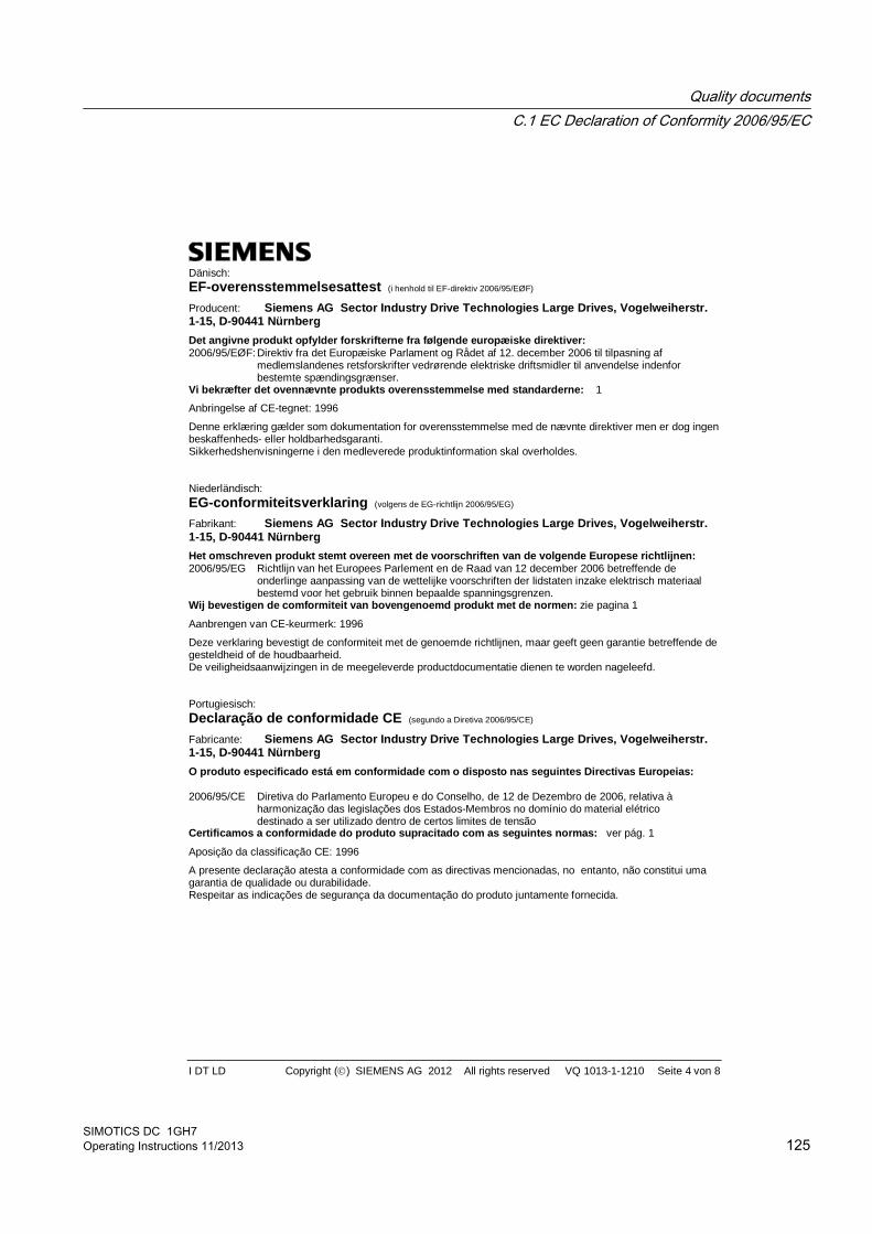
I DT LD Copyright ( ) SIEMENS AG 2012 All rights reserved VQ 1013-1-1210 Seite 4 von 8
Dänisch: EF-overensstemmelsesattest (i henhold til EF-direktiv 2006/95/EØF)
Producent: Siemens AG Sector Industry Drive Technologies Large Drives, Vogelweiherstr. 1-15, D-90441 Nürnberg
Det angivne produkt opfylder forskrifterne fra følgende europæiske direktiver: 2006/95/EØF: Direktiv fra det Europæiske Parlament og Rådet af 12. december 2006 til tilpasning af
medlemslandenes retsforskrifter vedrørende elektriske driftsmidler til anvendelse indenfor bestemte spændingsgrænser.
Vi bekræfter det ovennævnte produkts overensstemmelse med standarderne: 1
Anbringelse af CE-tegnet: 1996
Denne erklæring gælder som dokumentation for overensstemmelse med de nævnte direktiver men er dog ingen beskaffenheds- eller holdbarhedsgaranti. Sikkerhedshenvisningerne i den medleverede produktinformation skal overholdes. Niederländisch: EG-conformiteitsverklaring (volgens de EG-richtlijn 2006/95/EG)
Fabrikant: Siemens AG Sector Industry Drive Technologies Large Drives, Vogelweiherstr. 1-15, D-90441 Nürnberg
Het omschreven produkt stemt overeen met de voorschriften van de volgende Europese richtlijnen: 2006/95/EG Richtlijn van het Europees Parlement en de Raad van 12 december 2006 betreffende de onderlinge aanpassing van de wettelijke voorschriften der lidstaten inzake elektrisch materiaal bestemd voor het gebruik binnen bepaalde spanningsgrenzen. Wij bevestigen de comformiteit van bovengenoemd produkt met de normen: zie pagina 1
Aanbrengen van CE-keurmerk: 1996
Deze verklaring bevestigt de conformiteit met de genoemde richtlijnen, maar geeft geen garantie betreffende de gesteldheid of de houdbaarheid. De veiligheidsaanwijzingen in de meegeleverde productdocumentatie dienen te worden nageleefd. Portugiesisch: Declaração de conformidade CE (segundo a Diretiva 2006/95/CE)
Fabricante: Siemens AG Sector Industry Drive Technologies Large Drives, Vogelweiherstr. 1-15, D-90441 Nürnberg
O produto especificado está em conformidade com o disposto nas seguintes Directivas Europeias: 2006/95/CE Diretiva do Parlamento Europeu e do Conselho, de 12 de Dezembro de 2006, relativa à harmonização das legislações dos Estados-Membros no domínio do material elétrico destinado a ser utilizado dentro de certos limites de tensão Certificamos a conformidade do produto supracitado com as seguintes normas: ver pág. 1
Aposição da classificação CE: 1996
A presente declaração atesta a conformidade com as directivas mencionadas, no entanto, não constitui uma garantia de qualidade ou durabilidade. Respeitar as indicações de segurança da documentação do produto juntamente fornecida.
Quality documentsC.1 EC Declaration of Conformity 2006/95/EC
SIMOTICS DC 1GH7Operating Instructions 11/2013 125

I DT LD Copyright ( ) SIEMENS AG 2012 All rights reserved VQ 1013-1-1210 Seite 5 von 8
Griechisch E 2006/95/ )
: Siemens AG Sector Industry Drive Technologies Large Drives, Vogelweiherstr. 1-15, D-90441 Nürnberg
: 2006/95/E 12 2006 .
: 1
CE: 1996
, .
. Polnisch: Deklaracja zgodno ci (wg dyrektywy WE 2006/95/WE)
Producent: Siemens AG Sector Industry Drive Technologies Large Drives, Vogelweiherstr. 1-15, D-90441 Nürnberg
Produkt odpowiada wymaganiom nast puj cych dyrektyw Unii Europejskiej: 2006/95/WE Dyrektywa Parlamentu Europejskiego i Rady z dnia 12 grudnia 2006 r. w sprawie harmonizacji ustawodawstw pa stw cz onkowskich odnosz cych si do sprz tu elektrycznego przewidzianego do stosowania w okre lonych granicach napi cia Producent deklaruje niniejszym, e opisany produkt jest zgodny z nast puj cymi standardami: patrz strona 1
ywanie znaku CE: 1996
Niniejsza deklaracja za wiadcza zgodno z wymienionymi dyrektywami, jednak nie stanowi gwarancji o w ciwo ciach lub trwa ci produktu. Nale y zapozna si ze wskazówkami bezpiecze stwa zawartych w do czonej dokumentacji produktu. Litauisch: EB atitikties deklaracija (pagal EB direktyv 2006/95/EB)
Gamintojas: Siemens AG Sector Industry Drive Technologies Large Drives, Vogelweiherstr. 1-15, D-90441 Nürnberg
Gaminys atitinka toliau nurodyt Europos direktyv specifikacijas: 2006/95/EB 2006 m. gruodžio 12 d. Europos Parlamento ir Tarybos direktyva 2006/95/EB d l valstybi nari statym , susijusi su elektrotechniniais gaminiais, skirtais naudoti tam tikrose tampos ribose, suderinimo Patvirtiname, kad pirmiau nurodyti gaminiai atitinka šiuos standartus: žr. p. 1.
Paženklintas CE ženklu: 1996
Ši deklaracija patvirtina atitikim nurodytoms direktyvoms, ta iau negarantuoja joki ypatybi ar tinkamumo naudoti termino.
tina laikytis pridedamoje gaminio dokumentacijoje pateikt sp jam nurodym .
Quality documentsC.1 EC Declaration of Conformity 2006/95/EC
SIMOTICS DC 1GH7126 Operating Instructions 11/2013
I DT LD Copyright ( ) SIEMENS AG 2012 All rights reserved VQ 1013-1-1210 Seite 6 von 8
Lettisch: EK atbilst bas deklar cija (saska ar EK Direkt vu 2006/95/EK)
Ražot js: Siemens AG Sector Industry Drive Technologies Large Drives, Vogelweiherstr. 1-15, D-90441 Nürnberg
Ražojums atbilst turpm k min to Eiropas direkt vu specifik cij m: 2006/95/EK Eiropas Parlamenta un Padomes Direkt va 2006/95/EK (2006.gada12.decembris) par dal bvalstu ties bu aktu saska ošanu attiec uz elektroiek rt m, kas paredz tas lietošanai noteikt s sprieguma robež s Ar šo dokumentu apliecin m, ka iepriekš aprakst tais izstr jums atbilst š m pras m: skat t 1. lappusi.
CE z mes uzlikšana: 1996
deklar cija apliecina atbilst bu nor taj m direkt m, bet t negarant atbilst bu nor taj m izstr juma paš m vai kalpošanas ilgumam.
iev ro droš bas nor jumi, kas ietverti pieg des komplekt iek autaj izstr juma dokument cij . Estnisch: EÜ vastavusdeklaratsioon (EÜ direktiivi 2006/95/EÜ alusel)
Tootja: Siemens AG Sector Industry Drive Technologies Large Drives, Vogelweiherstr. 1-15, D-90441 Nürnberg
Toode vastab järgmiste Euroopa direktiivide spetsifikatsioonidele: 2006/95/EÜ Euroopa Parlamendi ja Nõukogu direktiiv 12. detsembrist 2006 liikmesriikides teatud pingevahemikes käitatavaid elektriseadmeid käsitlevate õigusaktide ühtlustamise kohta Käesolevaga avaldame, et eespool kirjeldatud toode vastab järgmistele normidele: vt lk 1.
Näidatud on CE-märgistus: 1996
Käesolev deklaratsioon tõendab vastavust nimetatud direktiividele, ei kujuta endast aga tooteomadus- ega vastupidavusgarantiid. Tarnimisel kaasaantud tootedokumentatsioonis äratoodud ohutusjuhistest tuleb kinni pidada. Tschechisch: ES Prohlášení o shod (podle sm rnice Evropského parlamentu a Rady 2006/95/ES)
Výrobce: Siemens AG Sector Industry Drive Technologies Large Drives, Vogelweiherstr. 1-15, D-90441 Nürnberg
Doty ný výrobek odpovídá specifikacím následujících evropských sm rnic: 2006/95/ES sm rnice Evropského parlamentu a Rady ze dne 12. prosince 2006 o harmonizaci právních p edpis lenských stát týkajících se elektrických za ízení ur ených pro používání v ur itých mezích nap tí Prohlašujeme tímto, že výše popsaný výrobek spl uje následující normy: viz str. 1
Zobrazení zna ky CE: 1996
Toto prohlášení osv uje shodu s uvedenými sm rnicemi, neznamená však záruku vlastností nebo trvanlivosti. Dodržujte bezpe nostní pokyny podle dodané dokumentace k výrobku.
Quality documentsC.1 EC Declaration of Conformity 2006/95/EC
SIMOTICS DC 1GH7Operating Instructions 11/2013 127

I DT LD Copyright ( ) SIEMENS AG 2012 All rights reserved VQ 1013-1-1210 Seite 7 von 8
Slowakisch: ES Prehlásenie o zhode (pod a smernice Európskeho parlamentu a Rady 2006/95/ES)
Výrobca: Siemens AG Sector Industry Drive Technologies Large Drives, Vogelweiherstr. 1-15, D-90441 Nürnberg
Daný výrobok zodpovedá špecifikáciám nasledovných európskych smerníc: 2006/95/ES smernica Európskeho parlamentu a Rady zo d a 12. decembra 2006 o harmonizácii právnych predpisov lenských štátov týkajúcich sa elektrických zariadení ur ených pre používanie v ur itých rozmedziach napätia Týmto prehlasujeme, že vyššie opísaný výrobok sp a nasledovné normy: vi str. 1
Zobrazenie ozna enia CE: 1996
Toto prehlásenie osved uje zhodu s uvedenými smernicami, neznamená však záruku vlastností alebo trvanlivosti. Dodržiavajte bezpe nostné pokyny pod a dodanej dokumentácie k výrobku. Ungarisch: EK Megfelel ségi nyilatkozat (a 2006/95/EK irányelv szerint)
Termék gyártója: Siemens AG Sector Industry Drive Technologies Large Drives, Vogelweiherstr. 1-15, D-90441 Nürnberg
Az itt megnevezett termék megfelel a következ európai irányelvek el írásainak: 2006/95/EK Az Európai Parlament és a Tanács 2006 december 12-én elfogadott irányelve a meghatározott
feszültsééghatáron belüli használatra tervezett elektromos berendezésekre vonatkozó tagállami jogszabályok összehangolásáról
Ezennel kijelentjük, hogy a fenti termék megfelel a következ szabványoknak: lásd 1. oldal
A CE jelölés feltüntetése: 1996
Ez a nyilatkozat tanúsítja a nevezett irányelveknek való megfelel séget, de semmilyen min ségi- vagy tartóssági garanciát nem jelent. A csatolt termékdokumentációban szerepl biztonsági utasításokat figyelembe kell venni. Slowenisch: Izjava o skladnosti ES (v skladu z ES-direktivo 2006/95/ES)
Proizvajalec: Siemens AG Sector Industry Drive Technologies Large Drives, Vogelweiherstr. 1-15, D-90441 Nürnberg
Opisani izdelek ustreza zahtevam naslednjih smernic Evropske Unije: 2006/95/ES Direktiva evropskega parlamenta in posveta z dne 12. decembra 2006 zaradi izena itve pravnih predpisov držav evropske skupnosti, ki se nanaša na elektri na obratna sredstva za uporabo znotraj dolo enih napetostnih mej Izjavljamo, da se zgoraj opisan izdelek sklada z naslednjimi standardi: glej stran 1
Uporaba znaka CE: 1996
Ta izjava potrjuje skladnost z navedenimi direktivami, vendar pa ni garancija za samo sestavo ali garancija za vsebnost. Treba je upoštevati varnostna opozorila priložene dokumentacije produkta.
Quality documentsC.1 EC Declaration of Conformity 2006/95/EC
SIMOTICS DC 1GH7128 Operating Instructions 11/2013
I DT LD Copyright ( ) SIEMENS AG 2012 All rights reserved VQ 1013-1-1210 Seite 8 von 8
Rumänisch: Declara ie de conformitate CE (conform Directivei CE 2006/95/CE) Produc tor: Siemens AG Sector Industry Drive Technologies Large Drives, Vogelweiherstr. 1-15, D-90441 Nürnberg Produsul descris aici respect prevederile urm toarelor Directive Europene: 2006/95/CE Directiva Parlamentului i Consiliului European din 12 decembrie 2006 pentru armonizarea
legisla iei statelor membre cu privire la mijloacele de produc ie electrice destinate utiliz rii între anumite limite de tensiune.
Confirm m prin prezenta conformitatea produsului mai sus men ionat cu urm toarele norme: 1
Aplicarea marcajului CE: 1996 Aceast declara ie confirm conformitatea cu directivele men ionate, îns nu reprezint o garan ie a calit ii sau fiabilit ii. Trebuie respectate indica iile de siguran din documenta ia livrat cu produsul. Bulgarisch: EO- ( EO- 2006/95/EO)
: Siemens AG Sector Industry Drive Technologies Large Drives, Vogelweiherstr. 1-15, D-90441 Nürnberg
: 2006/95/EO 12 2006
.
: 1 : 1996
, .
, .
Quality documentsC.1 EC Declaration of Conformity 2006/95/EC
SIMOTICS DC 1GH7Operating Instructions 11/2013 129

Quality documentsC.1 EC Declaration of Conformity 2006/95/EC
SIMOTICS DC 1GH7130 Operating Instructions 11/2013

Checklists D
When carrying out any work on the machine, observe the general safety instructions (Page 13) and the specifications contained in EN 50110‑1 regarding safe operation on electrical equipment.
SIMOTICS DC 1GH7Operating Instructions 11/2013 131
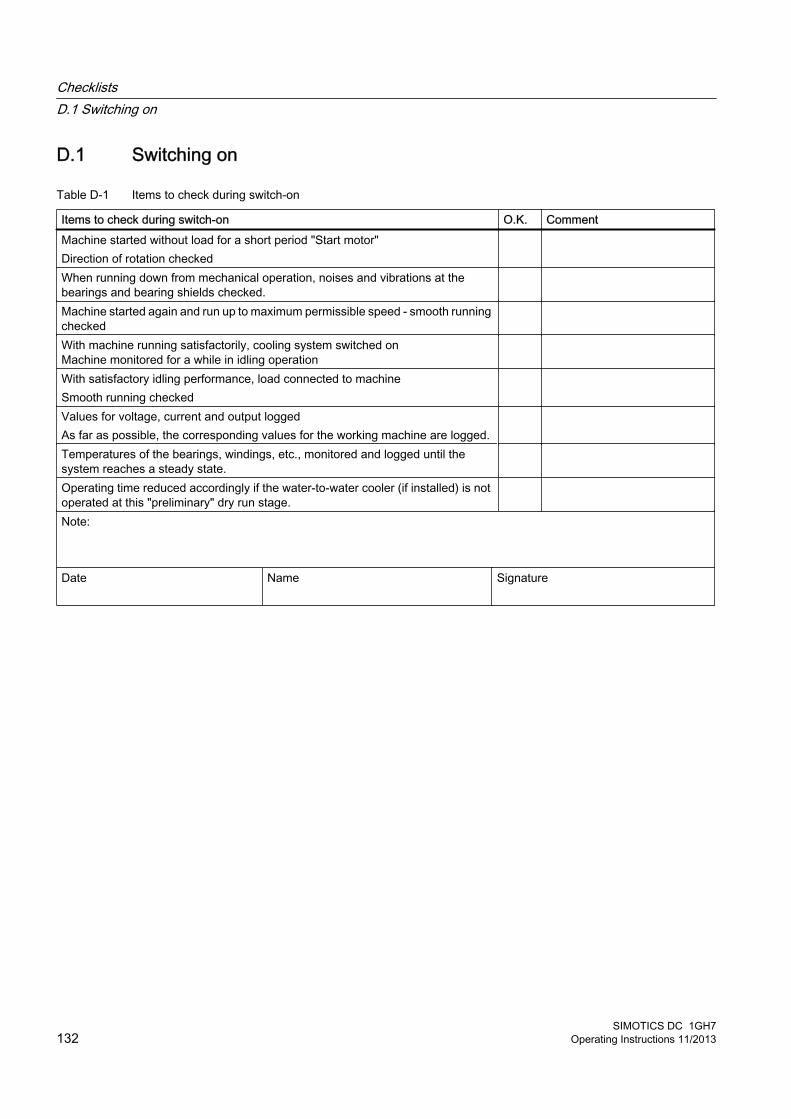
D.1 Switching on
Table D-1 Items to check during switch-on
Items to check during switch-on O.K. CommentMachine started without load for a short period "Start motor"Direction of rotation checked
When running down from mechanical operation, noises and vibrations at the bearings and bearing shields checked.
Machine started again and run up to maximum permissible speed - smooth running checked
With machine running satisfactorily, cooling system switched onMachine monitored for a while in idling operation
With satisfactory idling performance, load connected to machine Smooth running checked
Values for voltage, current and output loggedAs far as possible, the corresponding values for the working machine are logged.
Temperatures of the bearings, windings, etc., monitored and logged until the system reaches a steady state.
Operating time reduced accordingly if the water-to-water cooler (if installed) is not operated at this "preliminary" dry run stage.
Note: Date
Name Signature
ChecklistsD.1 Switching on
SIMOTICS DC 1GH7132 Operating Instructions 11/2013
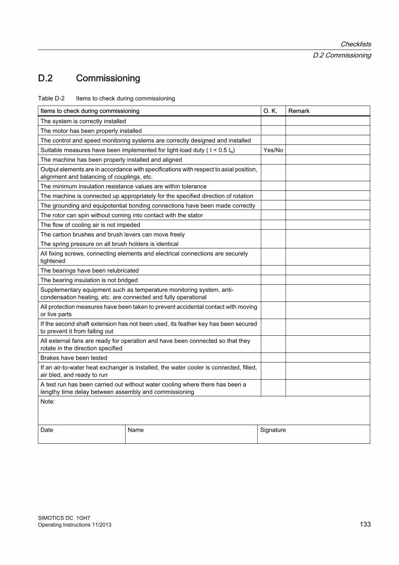
D.2 Commissioning
Table D-2 Items to check during commissioning
Items to check during commissioning O. K. RemarkThe system is correctly installed The motor has been properly installed The control and speed monitoring systems are correctly designed and installed Suitable measures have been implemented for light-load duty ( I < 0.5 IN) Yes/No The machine has been properly installed and aligned Output elements are in accordance with specifications with respect to axial position, alignment and balancing of couplings, etc.
The minimum insulation resistance values are within tolerance The machine is connected up appropriately for the specified direction of rotation The grounding and equipotential bonding connections have been made correctly The rotor can spin without coming into contact with the stator The flow of cooling air is not impeded The carbon brushes and brush levers can move freelyThe spring pressure on all brush holders is identical
All fixing screws, connecting elements and electrical connections are securely tightened
The bearings have been relubricated The bearing insulation is not bridged Supplementary equipment such as temperature monitoring system, anti-condensation heating, etc. are connected and fully operational
All protection measures have been taken to prevent accidental contact with moving or live parts
If the second shaft extension has not been used, its feather key has been secured to prevent it from falling out
All external fans are ready for operation and have been connected so that they rotate in the direction specified
Brakes have been tested If an air-to-water heat exchanger is installed, the water cooler is connected, filled, air bled, and ready to run
A test run has been carried out without water cooling where there has been a lengthy time delay between assembly and commissioning
Note: Date
Name Signature
ChecklistsD.2 Commissioning
SIMOTICS DC 1GH7Operating Instructions 11/2013 133
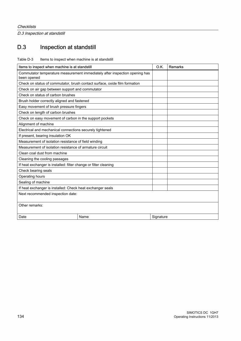
D.3 Inspection at standstill
Table D-3 Items to inspect when machine is at standstill
Items to inspect when machine is at standstill O.K. RemarksCommutator temperature measurement immediately after inspection opening has been opened
Check on status of commutator, brush contact surface, oxide film formation Check on air gap between support and commutator Check on status of carbon brushes Brush holder correctly aligned and fastened Easy movement of brush pressure fingers Check on length of carbon brushes Check on easy movement of carbon in the support pockets Alignment of machine Electrical and mechanical connections securely tightened If present, bearing insulation OK Measurement of isolation resistance of field winding Measurement of isolation resistance of armature circuit Clean coal dust from machine Cleaning the cooling passages If heat exchanger is installed: filter change or filter cleaning Check bearing seals Operating hours Sealing of machine If heat exchanger is installed: Check heat exchanger seals Next recommended inspection date: Other remarks: Date Name Signature
ChecklistsD.3 Inspection at standstill
SIMOTICS DC 1GH7134 Operating Instructions 11/2013
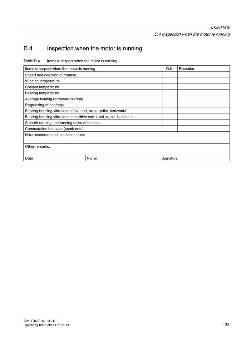
D.4 Inspection when the motor is running
Table D-4 Items to inspect when the motor is running
Items to inspect when the motor is running O.K. RemarksSpeed and direction of rotation Winding temperature Coolant temperature Bearing temperature Average loading (armature current) Regreasing of bearings Bearing-housing vibrations, drive end, axial, radial, horizontal Bearing-housing vibrations, non-drive end, axial, radial, horizontal Smooth running and running noise of machine Commutation behavior (spark note) Next recommended inspection date: Other remarks: Date Name Signature
ChecklistsD.4 Inspection when the motor is running
SIMOTICS DC 1GH7Operating Instructions 11/2013 135

ChecklistsD.4 Inspection when the motor is running
SIMOTICS DC 1GH7136 Operating Instructions 11/2013

Index
AAir gap torques, 24Aligning, 44, 47
Accuracy, 48Prerequisites, 37
Ambient conditions, 20Anti-condensation heating
Insulation resistance, 37Applications, 19Armature circuit, 63, 66Assembly
Bolt locking elements, 92Speed sensor, 94Speed sensor for construction type IM B5, 98Speed sensor for overhung mounting, 96Speed sensor with conical hub, 95
Auxiliary circuit, 22Connection, 56
Auxiliary circuits, 52Axial force, 48Axial gap, 46
BBalance quality, 40Bearing bushes
Drive end, 22Non-drive end, 22
Bearing seizure damage, 29Belt output, 49Belt tension, 49Bolt locking device, 119Brush height, 84Brush holder, 86Brush monitoring, 57Brush replacement, 85Brush rocker, 86
CCable entry, 51Carbon brushes, 84
Mounting, 85Removal, 85Replacement, 85Spare parts, 101
Cassette filter, 84Center of gravity, 27, 42Centering flange, 47Check list
Commissioning, 133Inspection, 134Switching on, 132
Condensate, 66Connecting cables
Selection of, 51Connection, 52
with cable lugs, 53without cable lugs, 54
Contacts, 117Converter, 60Cooling, 19Cooling method, 19Correct usage, 21Corrosion protection, 32
Removing, 39
DDamage during transportation, 25Deactivating, 63Degree of protection, 20, 22, 43Delivery, 25Disassembly
Machine, 90Speed sensor for construction type IM B5, 97Speed sensor for overhung mounting, 96Speed sensor with conical hub, 94
Disconnecting wiring, 91Disposal
Chemicals, 116Components, 115
EElectromagnetic compatibility, 17Electromagnetic fields, 18Emergency off, 67Emitted interference, 18Equipotential bonding, 56
Internal, 56Equipotential bonding connection, 56ESD guidelines, 16
SIMOTICS DC 1GH7Operating Instructions 11/2013 137

Ffaults, 66Faults, 72
Brushes, 74Commutator, 75Inspection , 71Roller bearings, 73
Feather key, 41Five safety rules, 13Flammable substances, 15Follow-up inspection, 78Foundation surfaces, 37
GGeneral inspection, 80Geometry of the flange, 37Grease types, 82Grounding conductor, 55
HHazardous substances, 15Hearing damage, 16, 23Hot surfaces , 15
IInitial inspection, 78Inspection
Faults, 71Insulation class, 20Insulation resistance, 34, 60, 69
Anti-condensation heating, 37Critical, 37measure, 35
Interference immunity, 17
LLifting, 27, 29, 42Local service , 117Long-term storage, 31Low-Voltage Directive, 13
MMachine
Aligning to the driven machine , 45Assembly, 92Disassembly, 91Placing, 43Securing, 45
Machine design, 20Machine expansion, 46Machine type, 101Main circuit, 22Maintenance
Maintenance intervals, 77Maintenance intervals, 80Minimum radial forces, 61More information, 117Mounting, 48Mounting parts, 34Mounting-foot hole dimensions, 37
NNatural installation frequency , 66Neutral zone, 91Noise emissions, 16, 23
OOperating mode, 23Operating under light-load conditions, 70Output element, 40Overspeed, 63, 66Overspeeds, 23
PPaint system, 89Paintwork damage, 89Periods of non-operation
Decommissioning, 68Lubricating before commissioning, 69Shaft grounding device, 69
Placing, 43Polarization index, 34, 60, 69Positioning, 45Precision alignment, 46Property class, 45
Index
SIMOTICS DC 1GH7138 Operating Instructions 11/2013
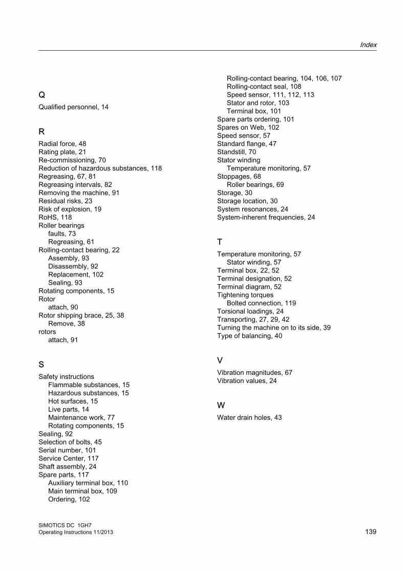
QQualified personnel, 14
RRadial force, 48Rating plate, 21Re-commissioning, 70Reduction of hazardous substances, 118Regreasing, 67, 81Regreasing intervals, 82Removing the machine, 91Residual risks, 23Risk of explosion, 19RoHS, 118Roller bearings
faults, 73Regreasing, 61
Rolling-contact bearing, 22Assembly, 93Disassembly, 92Replacement, 102Sealing, 93
Rotating components, 15Rotor
attach, 90Rotor shipping brace, 25, 38
Remove, 38rotors
attach, 91
SSafety instructions
Flammable substances, 15Hazardous substances, 15Hot surfaces, 15Live parts, 14Maintenance work, 77Rotating components, 15
Sealing, 92Selection of bolts, 45Serial number, 101Service Center, 117Shaft assembly, 24Spare parts, 117
Auxiliary terminal box, 110Main terminal box, 109Ordering, 102
Rolling-contact bearing, 104, 106, 107Rolling-contact seal, 108Speed sensor, 111, 112, 113Stator and rotor, 103Terminal box, 101
Spare parts ordering, 101Spares on Web, 102Speed sensor, 57Standard flange, 47Standstill, 70Stator winding
Temperature monitoring, 57Stoppages, 68
Roller bearings, 69Storage, 30Storage location, 30System resonances, 24System-inherent frequencies, 24
TTemperature monitoring, 57
Stator winding, 57Terminal box, 22, 52Terminal designation, 52Terminal diagram, 52Tightening torques
Bolted connection, 119Torsional loadings, 24Transporting, 27, 29, 42Turning the machine on to its side, 39Type of balancing, 40
VVibration magnitudes, 67Vibration values, 24
WWater drain holes, 43
Index
SIMOTICS DC 1GH7Operating Instructions 11/2013 139

Index
SIMOTICS DC 1GH7140 Operating Instructions 11/2013

AA U162 declaration of Conformity 1G.5-7

Siemens AGIndustry SectorDrive Technologies and Industry AutomationP.O. Box 484890327 NUREMBERGGERMANY
www.siemens.com/drives


