SD-I-U-... Operating instructions UNIVERSAL gateway for serial diagnostic EN 1 1. About this document 1.1 Function This operating instructions manual provides all the information you need for the mounting, set-up and commissioning to ensure the safe operation and disassembly of the the product. The operating instructions must be available in a legible condition and a complete version in the vicinity of the device. 1.2 Target group: authorised qualified personnel All operations described in this operating instructions manual must be carried out by trained specialist personnel, authorised by the plant operator only. Please make sure that you have read and understood these operating instructions and that you know all applicable legislations regarding occupational safety and accident prevention prior to installation and putting the component into operation. The machine builder must carefully select the harmonised standards to be complied with as well as other technical specifications for the selection, mounting and integration of the components. 1.3 Explanation of the symbols used Information, hint, note: This symbol is used for identifying useful additional information. Caution: Failure to comply with this warning notice could lead to failures or malfunctions. Warning: Failure to comply with this warning notice could lead to physical injury and/or damage to the machine. Content 1 About this document 1.1 Function .............................................. 1 1.2 Target group: authorised qualified personnel .................. 1 1.3 Explanation of the symbols used ........................... 1 1.4 Appropriate use ........................................ 2 1.5 General safety instructions ............................... 2 1.6 Warning about misuse ................................... 2 1.7 Exclusion of liability ..................................... 2 2 Product description 2.1 Ordering code ......................................... 2 2.2 Purpose .............................................. 2 2.3 Technical data ......................................... 2 3 Mounting 3.1 General mounting instructions ............................. 3 4 Electrical connection 4.1 General information for electrical connection.................. 3 5 Installation and operation 5.1 Installation SD interface .................................. 3 5.2 Installation field bus ..................................... 3 5.3 LED Signals ........................................... 3 5.4 UNIVERSAL gateway commissioning ....................... 3 6 Settings 6.1 Field bus system settings................................. 4 6.2 Transmission parameter setting (Baud rate) .................. 4 7 Teaching in SD devices 7.1 Teaching in SD devices (Teach function) ..................... 5 7.2 Teaching in SD devices (Teach function) with fixed address range ................................. 5 8 Communication 8.1 Communication with downstream PLC ...................... 5 8.2 UNIVERSAL gateway field bus data ........................ 5 8.3 SD slave field bus data .................................. 5 8.4 Arrangement of the SD bytes in the field bus protocol........... 6 8.5 Reading acyclic data from an SD slave ...................... 6 8.6 Table 1: Command overview and response data............... 6 8.7 Table 2: SD master diagnostics, SD system error .............. 7 8.8 Table 3: SD slave condition data ........................... 7 8.9 Table 4: SD slave diagnostics data ......................... 8 9 Wiring example 9.1 Series wiring evaluation .................................. 8 10 Description of field bus modules 10.1 PROFINET IO ........................................ 9 10.2 PROFINET IRT (Integrated Switch) ...................... 10 10.3 Ethernet/IP ......................................... 11 10.4 DeviceNet .......................................... 12 10.5 CC-Link ............................................ 13 10.6 CANopen........................................... 14 10.7 Modbus/TCP ........................................ 15 10.8 EtherCAT........................................... 16 11 EU Declaration of conformity x.000 / 01.2019 / v.A. - 101214305-EN / D / 2019-01-25 / AE-Nr. 9007 EN Operating instructions. . . . . . . . . . . .pages 1 to 18 Original
Transcript
SD-I-U-...Operating instructionsUNIVERSAL gateway for serial diagnostic
EN 1
1. About this document
1.1 FunctionThis operating instructions manual provides all the information you need for the mounting, set-up and commissioning to ensure the safe operation and disassembly of the the product. The operating instructions must be available in a legible condition and a complete version in the vicinity of the device.
1.2 Target group: authorised qualified personnelAll operations described in this operating instructions manual must be carried out by trained specialist personnel, authorised by the plant operator only.
Please make sure that you have read and understood these operating instructions and that you know all applicable legislations regarding occupational safety and accident prevention prior to installation and putting the component into operation.
The machine builder must carefully select the harmonised standards to be complied with as well as other technical specifications for the selection, mounting and integration of the components.
1.3 Explanation of the symbols used
Information, hint, note:This symbol is used for identifying useful additional information.
Caution: Failure to comply with this warning notice could lead to failures or malfunctions.Warning: Failure to comply with this warning notice could lead to physical injury and/or damage to the machine.
EN Operating instructions. . . . . . . . . . . .pages 1 to 18Original
2
Operating instructionsUNIVERSAL gateway for serial diagnostic SD-I-U-...
EN
1.4 Appropriate useThe product must be exclusively used in accordance with the versions listed below or for the applications authorised by the manufacturer. Detailed information regarding the range of applications can be found in the chapter "Product description".
1.5 General safety instructionsThe user must observe the safety instructions in this operating instructions manual, the country specific installation standards as well as all prevailing safety regulations and accident prevention rules.
Further technical information can be found in the Schmersal catalogues or in the online catalogue on the Internet: www.schmersal.net.
The information contained in this operating instructions manual is provided without liability and is subject to technical modifications.
There are no residual risks, provided that the safety instructions as well as the instructions regarding mounting, commissioning, operation and maintenance are observed.
1.6 Warning about misuse
In case of inadequate or improper use or manipulations of the component, personal hazards or damage to machinery or plant components cannot be excluded.
1.7 Exclusion of liabilityWe shall accept no liability for damages and malfunctions resulting from defective mounting or failure to comply with this operating instructions manual. The manufacturer shall accept no liability for damages resulting from the use of unauthorised spare parts or accessories.
For safety reasons, invasive work on the device as well as arbitrary repairs, conversions and modifications to the device are strictly forbidden; the manufacturer shall accept no liability for damages resulting from such invasive work, arbitrary repairs, conversions and/or modifications to the device.
2. Product description
2.1 Ordering codeThis operating instructions manual applies to the following types:
2.2 PurposeThe SD-I-U-…UNIVERSAL gateway is used in conjunction with safety sensors, solenoid interlocks and control panels with serial diagnostics. In these components, the diagnostic output is replaced with a serial input and output cable.If components with serial diagnostics are wired in series, the inputs and outputs of the diagnostic channels as well as the safety circuits are wired in series.
In this way, a series-wired chain of maximum 31 either identical or different components can be set up. For the evaluation, the serial diagnostic cable is connected to the here-described UNIVERSAL gateway. The gateway converts the serial information of the series wiring into the corresponding field bus protocol. The gate way is integrated as a slave into the available field bus system. The diagnostics signals of all SD devices can be evaluated by the control system via the field bus master.
Operational conditions can be read and control commands e.g. to unlock a solenoid interlock, which is installed on the components of the series-wired chain, can be transmitted. The status or failure information of each individual component of the series-wired chain is automatically loaded in the PLC.
The UNIVERSAL gateway does not realise safety tasks. The safety monitoring of the safety switching appliances must be realised independently.
(stabilised PELV)Fuse rating: external fuse 1 A slow blowPower consumption at 24 VDC: max. 500 mA, internally
fused plus load currentOperating temperature: – 5 °C to 55 °C,
in case of vertical positioningStorage temperature: – 25 °C … + 70 °CClimatic conditions: Humidity 30 % … 85 %,
no condensationProtection class: IP20Installation location: earthed, lockable
switch cabinet with min. protection class IP54Resistance to vibration: in case of installation between two side terminal
blocks on the standard DIN rail -in acc. with IEC 60068-2-6:10 to 57 Hz/0.35 mm
and 57 to 150 Hz/5 gResistance to shock - to IEC 60068-2-29: 10 gEMC rating: - in acc. with EN 61000-4-2 (ESD): ± 6 kV contact discharge /
± 8 kV air discharge - in acc. with EN 61000-4-3 (HF field): 10 V/m/80% AM - in acc. with EN 61000-4-4 (burst): ± 1 kV all connections - in acc. with EN 61000-4-5 (surge): ± 1 kV all connections - in acc. with EN 61000-4-6 (HF cables): 10 V all connections - in acc. with EN 61000-6-2 - in acc. with EN 61326-3-1 EMC emitted interference - in acc. with EN 61000-6-4: Emitted interference, industryRated insulation voltage Ui: 32 VRated impulse withstand voltage Uimp: 0.5 kVOvervoltage category: IIDegree of pollution: 2Dimensions (width/height/depth): 50 x 100 x 80 mm
(= height from standard DIN rail)Time to readiness after switch-on: 6 s
3
SD-I-U-...Operating instructionsUNIVERSAL gateway for serial diagnostic
EN
3. Mounting
3.1 General mounting instructionsThe SD-I-U- … UNIVERSAL gateway is designed as a control cabinet device with protection class IP20 for snapping onto a standard DIN rail. The device must be secured to the side terminal blocks on the standard DIN rail.
4. Electrical connection
4.1 General information for electrical connection
A PELV power supply with 24 VDC must be used. The current draw is a maximum of 500 mA. The power supply must be secured with a 1 A slow-blow fuse.
Power connec-tor:
24 V + 24 VDC Power supply
GND 0 VDC, GND of power supply and GND of SD interface
FE Functional earth (optional)SD connector: SD Connection of SD interface,
with max. 31 devices
The UNIVERSAL gateway and all SD slaves must be connected to the same 24 V DC supply.
The SD interface is wired via standard control lines. The SD interface connecting cable connected to the UNIVERSAL gateway must have a maximum length of 200 m; its wiring capacitance must not exceed 50 nF. Standard control lines of type LiYY or H05VV-F with cross sections of 0.25 mm² to 1.5 mm² have a wiring capacitance of approx. 30 - 45 nF with a length of 200 m.
5. Installation and operation
5.1 Installation SD interfaceElectronic safety sensors and solenoid interlocks must be interconnected in accordance with the technical data of the individual sensors. The safety channels and diagnostics channels are series wired.To this end, the serial diagnostics cable is connected from device to device and fed to the UNIVERSAL gateway. The SD connection of the UNIVERSAL gateway is connected to the SD input on the first device in series. The SD output on the first device is connected to the SD input on the following device, and so on. The output on the final device is unused. Under no circumstances may the operating voltage or GND be connected to this output.
5.2 Installation field busThe field bus must be connected via standard field bus cables and a standard field bus connector (if appl., with integrated deactivatable terminating resistor).
All specifications regarding wiring, required terminating resistors and the maximum cable lengths in the selected field bus system must be observed.
5.3 LED SignalsSD-LED Green ON = SD interface normal operation
For a precise description of both LED signals "SD" and "Teach", please see Table 2 "SD master diagnostics, SD system error".
For a description of the function of the LEDs on the field bus module, see the description of the field bus modules from page 9
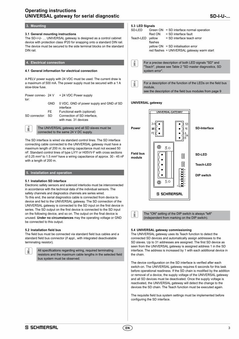
UNIVERSAL gateway
Power
Field bus module
SD-Interface
SD-LED
Teach-LED
DIP switch
The "ON" setting of the DIP switch is always "left" (independent from marking on the DIP switch).
5.4 UNIVERSAL gateway commissioningThe UNIVERSAL gateway uses its Teach function to detect the connected SD devices and automatically assign addresses to the SD slaves. Up to 31 addresses are assigned. The first SD device as seen from the UNIVERSAL gateway is assigned address 1 in the SD interface. The address is increased by 1 with each additional device in the chain.
The device configuration on the SD interface is verified after each switch-on. The UNIVERSAL gateway requires 6 seconds for this task before operational readiness. If the SD chain is modified by the addition or removal of a device, the supply voltage of the UNIVERSAL gateway and all SD devices must be deactivated. Once the supply voltage is reactivated, the UNIVERSAL gateway will detect the change to the devices the SD chain. The Teach function must be executed again.
The requisite field bus system settings must be implemented before configuring the SD interface.
4
Operating instructionsUNIVERSAL gateway for serial diagnostic SD-I-U-...
EN
6. Settings
6.1 Field bus system settingsThe field bus for communication with the control system is determined by the communication module integrated into the UNIVERSAL gateway. Address and transmission parameter (Baud rate) settings must be implemented on the UNIVERSAL gateway functioning as a field bus slave, according to the field bus being used. These settings must be made at the time of initial configuration, but may be modified later.
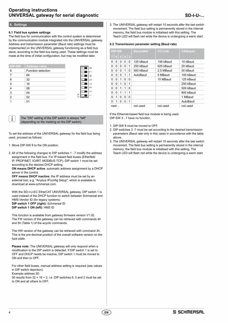
DIP-SW Address value 8 Function selection7 646 325 164 083 042 021 01
The "ON" setting of the DIP switch is always "left" (depending on the marking on the DIP switch).
To set the address of the UNIVERSAL gateway for the field bus being used, proceed as follows:
1. Move DIP-SW 8 to the ON position.
2. All of the following changes to DIP switches 1 - 7 modify the address assignment in the field bus. For IP-based field buses (EtherNet/IP, PROFINET, IO/IRT, MODBUS TCP), DIP switch 1 must be set according to the desired DHCP setting. ON means DHCP active: automatic address assignment by a DHCP server in the control. OFF means DHCP inactive: the IP address must be set by an external tool, e.g. "Anybus IPconfig Setup", which is available to download at www.schmersal.com. With the SD-I-U-EC EtherCAT UNIVERSAL gateway, DIP switch 1 is used instead of the DHCP function to switch between Schmersal and HMS-Vendor ID (for legacy systems) DIP switch 1 OFF (right): Schmersal ID DIP switch 1 ON (left): HMS ID This function is available from gateway firmware version V1.02. The FW version of the gateway can be retrieved with commands 4h and 5h (Table 1) of the acyclic commands. The HW version of the gateway can be retrieved with command 3h. This is the pre-decimal position of the overall software version on the type plate. Please note: The UNIVERSAL gateway will only respond when a modification to the DIP switch is detected. If DIP switch 1 is set to OFF and DHCP needs be inactive, DIP switch 1 must be moved to ON and then to OFF. For other field buses, manual address setting is required (see values in DIP switch depiction). Example address 50: 50 results from 32 + 16 + 2, i.e. DIP switches 6, 5 and 2 must be set to ON and all others to OFF.
3. The UNIVERSAL gateway will restart 10 seconds after the last switch movement. The field bus setting is permanently stored in the internal memory; the field bus module is initialised with this setting. The Teach LED will flash red while the device is undergoing a warm start.
If the Ethernet-based field bus module is being used, DIP-SW 3 - 7 have no function.
1. DIP-SW 8 must be moved to OFF.2. DIP switches 3 -7 must be set according to the desired transmission
parameters (Baud rate only in this case) in accordance with the table above.
3. The UNIVERSAL gateway will restart 10 seconds after the last switch movement. The field bus setting is permanently stored in the internal memory; the field bus module is initialised with this setting. The Teach LED will flash red while the device is undergoing a warm start.
5
SD-I-U-...Operating instructionsUNIVERSAL gateway for serial diagnostic
EN
7. Teaching in SD devices
7.1 Teaching in SD devices (Teach function)The Teach function must be executed at the time of initial configuration and in the event that a device is added, replaced or removed. A flashing yellow Teach LED indicates a change to the SD structure. The SD chain must be taught in again.The Teach function can also be triggered by a command through the field bus, see Chapter 8.5 and 8.6.
Proceed as follows:1. Switch off the UNIVERSAL gateway and SD bus devices.2. Install the SD bus devices in the desired order.3. Move DIP-SW 8 and DIP-SW 1 to the OFF position, leave DIP-SW
3 - 7 for Baud rate unchanged.4. Switch on the UNIVERSAL gateway and SD bus devices. SD bus
devices must be switched on before the gateway is switched on.5. Wait until the SD LED lights up red continuously and the Teach LED
flashes (SD bus scan complete).6. Move DIP switch 1 from OFF to ON. This starts the Teach process.
Arrangement and identification of the SD bus devices on the bus are then stored in the memory and compared with the devices on the SD interface after each switch-on.
7. If necessary, move DIP-SW 8 and DIP-SW 1 back to the desired field bus setting.
8. The gateway will restart 10 seconds after the last movement of the switch. The field bus setting is saved and the field bus module initialised with this setting. The SD bus is then started and its devices compared with the saved list. If the SD devices are consistent with the saved list, the SD LED will light up green and the yellow Teach LED will go out once start-up is complete.
Please note that when adding and removing devices, the reassignment of the SD addresses will also modify the address range in the downstream control. Following a change on the SD interface, the data of the connected SD devices accordingly have different addresses.
7.2 Teaching in SD devices (Teach function) with fixed address range
This option is available from UNIVERSAL gateway firmware version V1.04 or V2.04 for option 2PN and can only be activated with Ethernet-based buses. With a fixed address range, 64 bytes are always transmitted from the UNIVERSAL gateway to or from the superordinate PLC, irrespective of how many SD bus slave devices have been installed. The 64 bytes are made up of 2 bytes for the UNIVERSAL gateway and 31 x 2 bytes for each slave.
The following steps must be carried out:1. Switch off the UNIVERSAL gateway and SD bus devices.2. Install the SD bus devices in the desired order.3. Switch on the SD bus devices and UNIVERSAL gateway. SD bus
devices must be switched on before the gateway is switched on.4. Wait until the SD LED lights up continuously and the Teach LED
flashes yellow (SD bus scan complete).5. Move DIP switch 8 to the OFF (right) position. 6. Move DIP switch 1 from OFF to ON. 7. The Teach process is started automatically after 10 seconds. The
arrangement and identification of the SD bus devices on the bus are then saved in the memory.
8. Move DIP switch 2 to ON (left).9. Move DIP switch 1 and 3 - 7 to OFF (right). 10. The field bus interface is reconfigured after a waiting period of 10
seconds. 64 bytes of input and output data are then replaced. If this option has been activated and the Teach function is executed, the field bus interface is not reconfigured as 64 bytes have already been exchanged on the field bus side.
8. Communication
8.1 Communication with downstream PLCThe UNIVERSAL gateway must be integrated into the field bus system as a SLAVE. Once the electrical connection has been completed, the field bus system and control must be configured.
The following specifications must be configured:1. Configure the PLC system hardware.2. Add and configure the field bus master.3. Install the corresponding device description files (ESI, GSD, GSDML
or EDS files).4. Integrate the UNIVERSAL gateway as a slave and configure the
number of SD slaves.5. Access to the input and output data must be defined word for word in
the control manufacturer's engineering framework. In the frameworks that permit free mapping of the data, the output data (control outputs) must firstly be assigned, followed by the input data (control inputs).
The ESI, GSD, GSDML or EDS files for the various field bus modules are available for download at www.schmersal.com.
The UNIVERSAL gateway functions as an interface between the control system and the electronic safety sensors and solenoid interlocks with serial diagnostics connected to the SD interface (of which there may be up to 31).
The switching conditions of the connected SD devices can be read in various detail into the PLC.1. SD master diagnostics, SD system error2. SD slave condition data3. SD slave diagnostics data4. Acyclic data request from SD slave
In addition, control commands can be transmitted from the PLC to the SD devices. (See Table 3 and Table 4).
8.2 UNIVERSAL gateway field bus data2 bytes are reserved for both the request and response of the field bus protocol for gateway diagnostics and the acyclic data request from SD slaves.
Request Byte 00 Command byte, acyclic data requestByte 01 SD slave address for acyclic data request
Response: Byte 00 Gateway diagnostics byte (see Table 2)Byte 01 Data byte, acyclic data request
The precise description of the acyclic data request from SD slaves can be found on page 6.
8.3 SD slave field bus data2 bytes are reserved for both the request and response of the field bus protocol for each SD slave.- SD slave 01 uses byte 02 and byte 03 from the field bus- SD slave 02 uses byte 04 and byte 05 from the field bus... etc.- SD slave 31 uses byte 62 and byte 63 from the field bus
In the request, only the first byte is required as the request byte for an SD slave on the field bus. The second byte is unused. In the response, the response byte is transferred from each SD slave on the field bus, followed by the diagnostics byte.
6
Operating instructionsUNIVERSAL gateway for serial diagnostic SD-I-U-...
EN
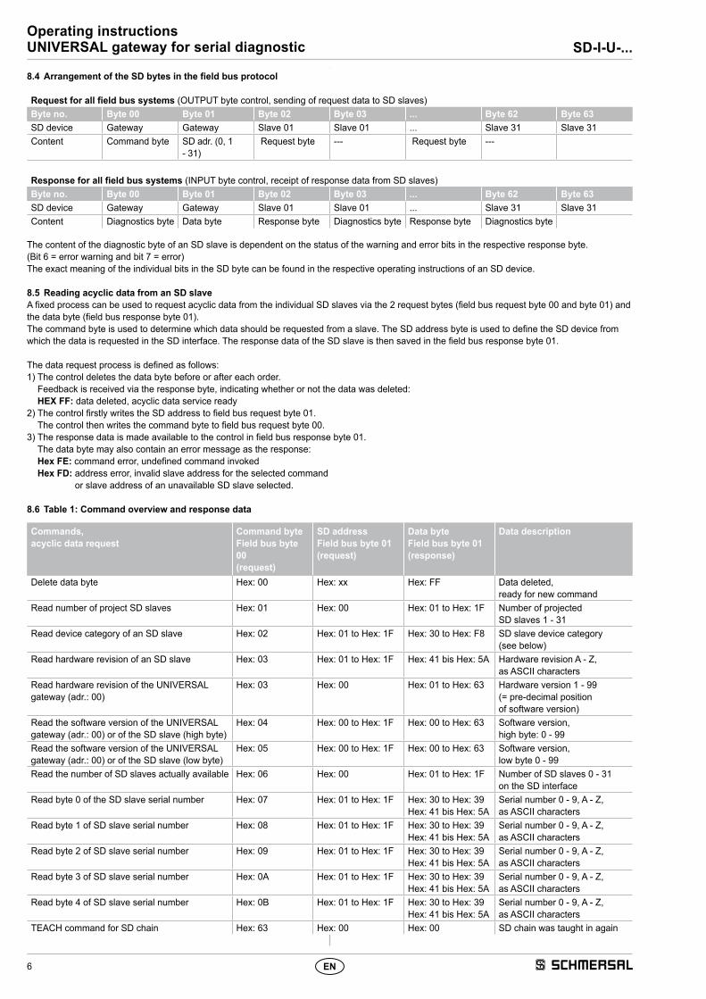
8.4 Arrangement of the SD bytes in the field bus protocol
Request for all field bus systems (OUTPUT byte control, sending of request data to SD slaves)Byte no. Byte 00 Byte 01 Byte 02 Byte 03 ... Byte 62 Byte 63SD device Gateway Gateway Slave 01 Slave 01 ... Slave 31 Slave 31Content Command byte SD adr. (0, 1
- 31) Request byte --- Request byte ---
Response for all field bus systems (INPUT byte control, receipt of response data from SD slaves)Byte no. Byte 00 Byte 01 Byte 02 Byte 03 ... Byte 62 Byte 63SD device Gateway Gateway Slave 01 Slave 01 ... Slave 31 Slave 31Content Diagnostics byte Data byte Response byte Diagnostics byte Response byte Diagnostics byte
The content of the diagnostic byte of an SD slave is dependent on the status of the warning and error bits in the respective response byte. (Bit 6 = error warning and bit 7 = error)The exact meaning of the individual bits in the SD byte can be found in the respective operating instructions of an SD device.
8.5 Reading acyclic data from an SD slaveA fixed process can be used to request acyclic data from the individual SD slaves via the 2 request bytes (field bus request byte 00 and byte 01) and the data byte (field bus response byte 01).The command byte is used to determine which data should be requested from a slave. The SD address byte is used to define the SD device from which the data is requested in the SD interface. The response data of the SD slave is then saved in the field bus response byte 01.
The data request process is defined as follows:1) The control deletes the data byte before or after each order.
Feedback is received via the response byte, indicating whether or not the data was deleted: HEX FF: data deleted, acyclic data service ready
2) The control firstly writes the SD address to field bus request byte 01. The control then writes the command byte to field bus request byte 00.
3) The response data is made available to the control in field bus response byte 01. The data byte may also contain an error message as the response: Hex FE: command error, undefined command invoked Hex FD: address error, invalid slave address for the selected command
or slave address of an unavailable SD slave selected.
8.6 Table 1: Command overview and response data
Commands, acyclic data request
Command byte Field bus byte 00 (request)
SD address Field bus byte 01 (request)
Data byte Field bus byte 01 (response)
Data description
Delete data byte Hex: 00 Hex: xx Hex: FF Data deleted, ready for new command
Read number of project SD slaves Hex: 01 Hex: 00 Hex: 01 to Hex: 1F Number of projected SD slaves 1 - 31
Read device category of an SD slave Hex: 02 Hex: 01 to Hex: 1F Hex: 30 to Hex: F8 SD slave device category (see below)
Read hardware revision of an SD slave Hex: 03 Hex: 01 to Hex: 1F Hex: 41 bis Hex: 5A Hardware revision A - Z, as ASCII characters
Read hardware revision of the UNIVERSAL gateway (adr.: 00)
Hex: 03 Hex: 00 Hex: 01 to Hex: 63 Hardware version 1 - 99 (= pre-decimal position of software version)
Read the software version of the UNIVERSAL gateway (adr.: 00) or of the SD slave (high byte)
Hex: 04 Hex: 00 to Hex: 1F Hex: 00 to Hex: 63 Software version, high byte: 0 - 99
Read the software version of the UNIVERSAL gateway (adr.: 00) or of the SD slave (low byte)
Hex: 05 Hex: 00 to Hex: 1F Hex: 00 to Hex: 63 Software version, low byte 0 - 99
Read the number of SD slaves actually available Hex: 06 Hex: 00 Hex: 01 to Hex: 1F Number of SD slaves 0 - 31 on the SD interface
Read byte 0 of the SD slave serial number Hex: 07 Hex: 01 to Hex: 1F Hex: 30 to Hex: 39Hex: 41 bis Hex: 5A
Serial number 0 - 9, A - Z, as ASCII characters
Read byte 1 of SD slave serial number Hex: 08 Hex: 01 to Hex: 1F Hex: 30 to Hex: 39Hex: 41 bis Hex: 5A
Serial number 0 - 9, A - Z, as ASCII characters
Read byte 2 of SD slave serial number Hex: 09 Hex: 01 to Hex: 1F Hex: 30 to Hex: 39Hex: 41 bis Hex: 5A
Serial number 0 - 9, A - Z, as ASCII characters
Read byte 3 of SD slave serial number Hex: 0A Hex: 01 to Hex: 1F Hex: 30 to Hex: 39Hex: 41 bis Hex: 5A
Serial number 0 - 9, A - Z, as ASCII characters
Read byte 4 of SD slave serial number Hex: 0B Hex: 01 to Hex: 1F Hex: 30 to Hex: 39Hex: 41 bis Hex: 5A
Serial number 0 - 9, A - Z, as ASCII characters
TEACH command for SD chain Hex: 63 Hex: 00 Hex: 00 SD chain was taught in again
7
SD-I-U-...Operating instructionsUNIVERSAL gateway for serial diagnostic
EN
The device category of an SD slave can be found in the respective operating instructions for the device.
The following device categories have already been defined:
Bit 1: –Bit 2: –Bit 3: –Bit 4: SD initialisation error SD chain must be reinitialised! Switch off gateway and SD slave opera-
ting voltage. There may be no SD slave connected!ON ON
Bit 5: SD Teach-in error Structure of SD chain changed after power-on! If OK, actuate TEACH. ON FlashesBit 6: SD-Short-circuit Short-circuit to SD interface cables.
Switch off and rectify error.ON Off
Bit 7: SD Communication error One or more SD slaves cannot be contacted. SD slave data no longer valid. Check SD installation, if necessary.
ON Off
8.8 Table 3: SD slave condition data
Content of SD slave request byte1st byte of SD slave in request in each case
Content of SD slave response byte1st byte of SD slave in response in each case
SD slave request byte PLC output byte
Response byte SD slavePLC input byte
Bit 0: Device-specific, e.g. AZM, MZM interlocks: "Magnet ON"
Bit 0: safety outputs enabled
Bit 1: --- Bit 1: Actuator detected
Bit 2: --- Bit 2: Device-specific (see SD device operating instructions)
Bit 3: --- Bit 3: Device-specific, e.g. CSS 34F: ready for release or reset signal
Bit 4: --- Bit 4: Input condition X1 AND X2
Bit 5: --- Bit 5: Device-specific (see SD device operating instructions)
Bit 6: --- Bit 6: Error warning present
Bit 7: Error reset Bit 7: Error (enabling path switched off)
8
Operating instructionsUNIVERSAL gateway for serial diagnostic SD-I-U-...
EN
8.9 Table 4: SD slave diagnostics data2nd byte of SD slave in response in each case
Depending on the status of bit 6 (warning) and 7 (error) in the response byte of the corresponding SD slave, the diagnostics byte contains the following data:
Response byte Content of diagnostics byte
Bit 7: Bit 6:0 0 ---0 1 Warning message (error warning)1 0 Error message (Error)1 1 Error message (Error)
The individual bits in the diagnostics byte of the SD slave have the following meaning:
Bit Error warning ErrorBit 0: Error output Y1 Error output Y1Bit 1: Error output Y2 Error output Y2Bit 2: Cross-wire short output Cross-wire short outputBit 3: Temperature too high SD
slaveTemperature too high SD slave
Bit 4: --- incorrect or defective actuator
Bit 5: Internal device error Internal device errorBit 6: SD communication error,
e.g. SD slave does not respond
Device-specific (see device operating instructions)
Bit 7: SD slave operating voltage too low
---
9. Wiring example
9.1 Series wiring evaluation
Sensor
X1 (IN) X1 (IN) X1 (IN)Y1 (OUT) Y1 (OUT) Y1 (OUT)
X2 (IN) X2 (IN) X2 (IN)Y2 (OUT) Y2 (OUT) Y2 (OUT)
SD-OUT SD-OUT SD-OUTSD-IN SD-IN SD-IN
SD-Interface
SD-I-DP-VO-2
PROFIBUS DP
SPS/PLC
Sensor Sensor
AuswertungSicherheits-
GatewayPROFIBUS-
Safety evalu-ation safety circuit
UNIVERSAL-Gateway
FIELDBUS
Accessories for the series-wiringFor convenient wiring and series-wiring of SD devices, the SD junction boxes PFB-SD-4M12-SD (variant for the field) and PDM-SD-4CC-SD (variant for control cabinet on carrier rail) are available along with additional comprehensive accessories.Detailed information is available on the Internet, www.schmersal.net.
9EN
SD-I-U-...Operating instructionsUNIVERSAL gateway for serial diagnostic
10. Description of field bus modules
10.1 PROFINET IO
About the Anybus-CompactCom PROFINET IO 1-2
Front View
Network Status LED
Note: A test sequence is performed on this LED during startup.
Module Status LED
Note: A test sequence is performed on this LED during startup.
LINK/Activity LED
Ethernet Interface
The ethernet interface operates at 100Mbit, full duplex, as required by PROFINET.
# Item1 Network Status LED
2 Module Status LED
3 Link/Activity LED
4 Ethernet Interface
LED State Description CommentsOff Offline - No power
- No connection with IO ControllerGreen Online (RUN) - Connection with IO Controller established
- IO Controller in RUN stateGreen, flashing Online (STOP) - Connection with IO Controller established
- IO Controller in STOP state
LED State Description CommentsOff Not Initialized No power - or - Module in ‘SETUP’ or ‘NW_INIT’ stateGreen Normal Operation Module has shifted from the ‘NW_INIT’ stateGreen, 1 flash Diagnostic Event(s) Diagnostic event(s) presentGreen, 2 flashes Blink Used by engineering tools to identify the node on the networkRed Exception Error Module in state ‘EXCEPTION’Red, 1 flash Configuration Error Expected Identification differs from Real IdentificationRed, 2 flashes IP Address Error IP address not setRed, 3 flashes Station Name Error Station Name not setRed, 4 flashes Internal Error Module has encountered a major internal error
LED State Description CommentsOff No Link No link, no communication presentGreen Link Ethernet link established, no communication presentGreen, flickering Activity Ethernet link established, communication present
4
81
1 2
3
10 EN
Operating instructionsUNIVERSAL gateway for serial diagnostic SD-I-U-...
SD-I-U-...Operating instructionsUNIVERSAL gateway for serial diagnostic
Description of field bus modules
10.3 Ethernet/IP
About the Anybus-CompactCom EtherNet/IP 1-2
Front View
Network Status LED
Note: A test sequence is performed on this LED during startup.
Module Status LED
Note: A test sequence is performed on this LED during startup.
LINK/Activity LED
Ethernet Interface
The ethernet interface supports 10/100Mbit, full or half duplex operation.
# Item1 Network Status LED
2 Module Status LED
3 Link/Activity
4 Ethernet Interface
LED State DescriptionOff No power or no IP addressGreen On-line, one or more connections established (CIP Class 1 or 3)Green, flashing On-line, no connections establishedRed Duplicate IP address, FATAL errorRed, flashing One or more connections timed out (CIP Class 1 or 3)
LED State DescriptionOff No powerGreen Controlled by a Scanner in Run stateGreen, flashing Not configured, or Scanner in Idle stateRed Major fault (EXCEPTION-state, FATAL error etc.)Red, flashing Recoverable fault(s)
LED State DescriptionOff No link, no activityGreen Link establishedGreen, flickering Activity
4
81
1 2
3
12 EN
Operating instructionsUNIVERSAL gateway for serial diagnostic SD-I-U-...
Description of field bus modules
10.4 DeviceNet
About the Anybus-CompactCom DeviceNet 1-2
Front View
Network Status
Module Status
DeviceNet Connector
This connector provides DeviceNet connectivity.
# Item1 Network Status LED2 Module Status LED3 DeviceNet Connector
State IndicationOff Not online / No powerGreen On-line, one or more connections are establishedFlashing Green (1 Hz) On-line, no connections establishedRed Critical link failureFlashing Red (1 Hz) One or more connections timed-outAlternating Red/Green Self test
State IndicationOff No powerGreen Operating in normal conditionFlashing Green (1 Hz) Missing or incomplete configuration, device needs commissioningRed Unrecoverable Fault(s)Flashing Red (1 Hz) Recoverable Fault(s)Alternating Red/Green Self test
Pin Signal Description1 V- Negative bus supply voltagea
a. DeviceNet bus power. For more information, see C-1 “Technical Specification”.
2 CAN_L CAN low bus line3 SHIELD Cable shield4 CAN_H CAN high bus line5 V+ Positive bus supply voltagea
13EN
SD-I-U-...Operating instructionsUNIVERSAL gateway for serial diagnostic
Description of field bus modules
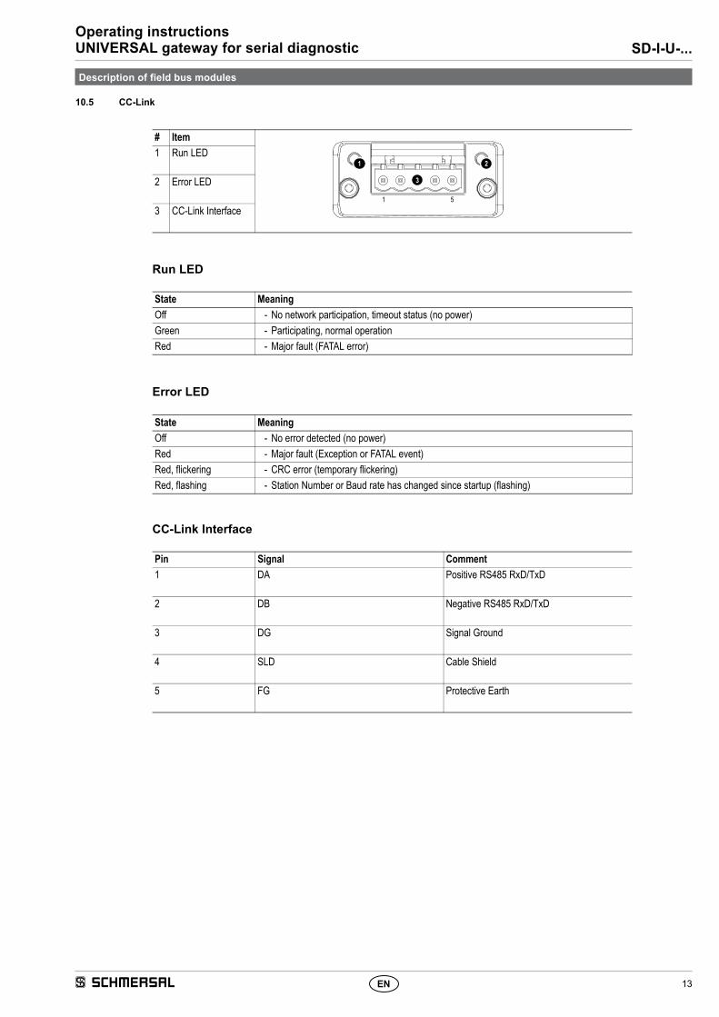
10.5 CC-Link
About the Anybus-CompactCom CC-Link 1-2
Front View
Run LED
Error LED
CC-Link Interface
# Item1 Run LED
2 Error LED
3 CC-Link Interface
State MeaningOff - No network participation, timeout status (no power)Green - Participating, normal operationRed - Major fault (FATAL error)
State MeaningOff - No error detected (no power)Red - Major fault (Exception or FATAL event)Red, flickering - CRC error (temporary flickering)Red, flashing - Station Number or Baud rate has changed since startup (flashing)
Pin Signal Comment1 DA Positive RS485 RxD/TxD
2 DB Negative RS485 RxD/TxD
3 DG Signal Ground
4 SLD Cable Shield
5 FG Protective Earth
1 2
3
1 5
14 EN
Operating instructionsUNIVERSAL gateway for serial diagnostic SD-I-U-...
Description of field bus modules
10.6 CANopen
About the Anybus-CompactCom CANopen 1-2
Front View
RUN LED
ERROR LED
CANopen Interface
# Item1 RUN LEDa
a. The flash sequences for these LEDs are defined in DR303-3 (CiA).
2 ERROR LEDa
3 CANopen Interface
LED State Indication DescriptionOff - No power.Green OPERATIONAL The module is in the ‘operational’ state.Green, blinking PRE-OPERATIONAL The module is in the ‘pre-operational’ state.Green, single flash STOPPED The module is in the ‘stopped’ state.Green, flickering Autobaud Baudrate detection in progress.Reda
a. If both LEDs turns red, this indicates a fatal event; the bus interface is shifted into a physically passive state.
EXCEPTON state (Fatal Event) The module has shifted into the EXCEPTION state.
LED State Indication DescriptionOff - No power - or - device is in working condition.Red, single flash Warning limit reached A bus error counter reached or exceeded its warning level.Red, flickering LSS LSS services in progress.Red, double flash Error Control Event A guard- (NMT-Slave or NMT-master) or heartbeat event
(Heartbeat consumer) has occurred.Reda
a. If both LEDs turns red, this indicates a fatal event; the bus interface is shifted into a physically passive state.
SD-I-U-...Operating instructionsUNIVERSAL gateway for serial diagnostic
Description of field bus modules
10.7 Modbus/TCP
About the Anybus-CompactCom Modbus/TCP 1-2
Front View
Network Status LED
Note: A test sequence is performed on this LED during startup.
Module Status LED
Note: A test sequence is performed on this LED during startup.
LINK/Activity LED
Ethernet Interface
The ethernet interface supports 10/100Mbit, full or half duplex operation.
# Item1 Network Status LED
2 Module Status LED
3 Link/Activity
4 Ethernet Interface
LED State DescriptionOff No power or no IP addressGreen Module is in Process Active or Idle stateGreen, flashing Waiting for connectionsRed Duplicate IP address, or FATAL eventRed, flashing Process Active Timeout.
LED State DescriptionOff No powerGreen Normal operationRed Major fault; module is in state EXCEPTION (or FATAL event)Red, flashing Minor fault; the present IP settings differs from the settings in the net.cfg.ob
LED State DescriptionOff No link, no activityGreen Link establishedGreen, flickering Activity
4
81
1 2
3
16 EN
Operating instructionsUNIVERSAL gateway for serial diagnostic SD-I-U-...
LED State Indication DescriptionOff INIT CoE device in ‘INIT’-state (or no power)Green OPERATIONAL CoE device in ‘OPERATIONAL’-stateGreen, blinking PRE-OPERATIONAL CoE device in ‘PRE-OPERATIONAL’-stateGreen, single flash SAFE-OPERATIONAL CoE device in ‘SAFE-OPERATIONAL’-stateReda
a. If RUN and ERR turns red, this indicates a fatal event, forcing the bus interface to a physically passive state.Contact HMS technical support.
(Fatal Event) -
LED State Indication DescriptionOff No error No error (or no power)Red, blinking Invalid configuration State change received from master is not possible due to
a. If RUN and ERR turns red, this indicates a fatal event, forcing the bus interface to a physically passive state.Contact HMS technical support.
Application controller failure Anybus module in EXCEPTION
LED State Indication DescriptionOff No link Link not sensed (or no power)Green Link sensed, no activity Link sensed, no traffic detectedGreen, flickering Link sensed, activity detected Link sensed, traffic detected
1 2
3
5 6
4
17EN
SD-I-U-...Operating instructionsUNIVERSAL gateway for serial diagnostic
SD-I-
U-C
-DE
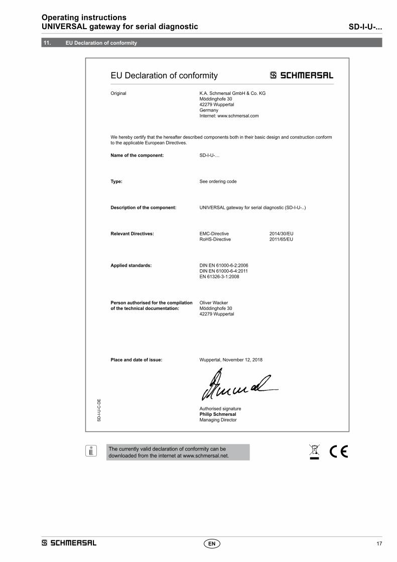
The currently valid declaration of conformity can be downloaded from the internet at www.schmersal.net.
Place and date of issue: Wuppertal, November 12, 2018
Authorised signaturePhilip SchmersalManaging Director
EU Declaration of conformity
Original K.A. Schmersal GmbH & Co. KGMöddinghofe 3042279 WuppertalGermanyInternet: www.schmersal.com
We hereby certify that the hereafter described components both in their basic design and construction conform to the applicable European Directives.
Name of the component: SD-I-U-…
Type: See ordering code
Description of the component: UNIVERSAL gateway for serial diagnostic (SD-I-U-..)
Relevant Directives: EMC-DirectiveRoHS-Directive
2014/30/EU2011/65/EU
Applied standards: DIN EN 61000-6-2:2006DIN EN 61000-6-4:2011EN 61326-3-1:2008
Person authorised for the compilation of the technical documentation:
Oliver WackerMöddinghofe 3042279 Wuppertal
11. EU Declaration of conformity
K.A. Schmersal GmbH & Co. KGMöddinghofe 30, D - 42279 WuppertalPostfach 24 02 63, D - 42232 Wuppertal