Before attempting to connect or operate this product, please read these instructions carefully and save this manual for future use. The model number is abbreviated in some descriptions in this manual. Model No. WV-CU360CJ/B WV-CU360CJ/G System Controller Operating Instructions System Controller WV-CU 360C OPERATE LOGIN ALARM MONITOR UNIT CAMERA BUSY PROHIBITED SHIFT FUNCTION CAM FUNCTION PROGRAM ALM RESET VCR CAM MULTI SCREEN SELECT STILL – SEQ PAUSE SEQUENCE SLOW PATROL LEARN PROGRAM PRESET PATROL STOP ESC SET LOGOUT MON CAM PATROL PLAY + AUX 1 WIPER HOME/PRESET AUX 2 DEF UNIT B ZOOM WIDE TELE DOWN L R UP EL-ZOOM ALM RECALL ALM SUSPEND AUTO FOCUS FAR NEAR UNIT A UNIT B/W SETUP CAM SETUP CLOSE IRIS OPEN IRIS RESET AUTO FOCUS 8 9 7 0 4 5 6 2 3 1 中 文 ENGLISH
Transcript
Before attempting to connect or operate this product,please read these instructions carefully and save this manual for future use.
The model number is abbreviated in some descriptions in this manual.
Model No. WV-CU360CJ/BWV-CU360CJ/G
System ControllerOperating Instructions
System Controller WV-CU 360C
OPERATE
LOGIN
ALARM MONITORUNIT
CAMERA
BUSY
PROHIBITED
SHIFT
FUNCTIONCAM FUNCTION
PROGRAM
ALM RESET
VCR CAMMULTI SCREEN SELECT
STILL
–SEQ PAUSE
SEQUENCESLOW
PATROLLEARN
PROGRAMPRESET
PATROLSTOP
ESC
SET
LOGOUT
MON
CAM
PATROL PLAY
+
AUX 1
WIPER
HOME/PRESET
AUX 2
DEF
UNIT B
ZOOMWIDE
TELE
DOWN
L
R
UP
EL-ZOOM
ALM RECALL
ALM SUSPENDAUTO
FOCUS
FAR
NEAR
UNIT A
UNIT
B/W
SETUPCAM SETUP
CLOSE IRIS
OPENIRIS RESET
AUTO FOCUS89
7
0
45
6
23
1
中文
ENGL
ISH
2
The serial number of this product may be found on the bot-tom of the unit.You should note the serial number of this unit in the spaceprovided and retain this book as a permanent record of yourpurchase to aid identification in the event of theft.
Model No. WV-CU360CJ
Serial No.
ENGLISH VERSION
The lightning flash with arrowhead symbol,within an equilateral triangle, is intended toalert the user to the presence of uninsulated"dangerous voltage" within the product's enclo-sure that may be of sufficient magnitude toconstitute a risk of electric shock to persons.
The exclamation point within an equilateral tri-angle is intended to alert the user to the pres-ence of important operating and maintenance(servicing) instructions in the literature accom-panying the appliance.
CAUTION: TO REDUCE THE RISK OF ELECTRIC SHOCK,
DO NOT REMOVE COVER (OR BACK).
NO USER-SERVICEABLE PARTS INSIDE.
REFER SERVICING TO QUALIFIED SERVICE PERSONNEL.
CAUTIONRISK OF ELECTRIC SHOCK
DO NOT OPEN
CAUTION:Before attempting to connect or operate this prod-uct, please read the label on the bottom.
We declare under our sole responsibility that the product to whichthis declaration relates is in conformity with the standards or othernormative documents following the provisions of Directives2006/95/EC and 2004/108/EC.
Nosotros declaramos bajo nuestra única responsabilidad que elproducto a que hace referencia esta declaración está conforme conlas normas u otros documentos normativos siguiendo lasestipulaciones de las directivas 2006/95/CE y 2004/108/CE.
Noi dichiariamo sotto nostra esclusiva responsabilità che il prodottoa cui si riferisce la presente dichiarazione risulta conforme aiseguenti standard o altri documenti normativi conformi alledisposizioni delle direttive 2006/95/CE e 2004/108/CE.
Wir erklären in alleiniger Verantwortung, daß das Produkt, auf dassich diese Erklärung bezieht, mit der folgenden Normen odernormativen Dokumenten übereinstimmt. Gemäß denBestimmungen der Richtlinie 2006/95/EC und 2004/108/EC.
Nous déclarons sous note seule responsabilité que le produitauquel se réfère la présente déclaration est conforme aux normesou autres documents normatifs conformément aux dispositions desdirectives 2006/95/CE et 2004/108/CE.
Wij verklaren als enige aansprakelijke, dat het product waarop dezeverklaring betrekking heeft, voldoet aan de volgende normen ofandere normatieve documenten, overeenkomstig de bepalingenvan Richtlijnen 2006/95/EC en 2004/108/EC.
Vi erklærer os eneansvarlige for, at dette produkt, som dennedeklaration omhandler, er i overensstemmelse med standarder ellerandre normative dokumenter i følge bestemmelserne i direktivene2006/95/EC og 2004/108/EC.
Vi deklarerar härmed värt fulla ansvar för att den produkt till vilkendenna deklaration hänvisar är i överensstämmelse medstandarddokument, eller andra normativa dokument som framställs idirektiv nr. 2006/95/EC och 2004/108/EC.
Ilmoitamme yksinomaisella vastuullamme, että tuote, jota tämäilmoitus koskee, noudattaa seuraavia standardeja tai muitaohjeellisia asiakirjoja, jotka noudattavat direktiivien 2006/95/EC ja2004/108/EC säädöksiä.
Vi erklærer oss alene ansvarlige for at produktet som denneerklæringen gjelder for, er i overensstemmelse med følgendenormer eller andre normgivende dokumenter som følgerbestemmelsene i direktivene 2006/95/EC og 2004/108/EC.
WARNING:• To prevent fire or electric shock hazard, do not expose this
apparatus to rain or moisture.• The apparatus should not be exposed to dripping or splashing
and that no objects filled with liquids, such as vases, should beplaced on the apparatus.
Chapter 1For Panasonic Security Data (PS •Data) Systems ........ 9MAJOR OPERATING CONTROLS & THEIR FUNCTIONS .... 10
� Front View (Template for PS •Data) .............................10INSTALLATIONS (PS •Data) .............................................. 13
� System Connections .................................................. 13� DIP Switch Setting (PS •Data) ..................................... 15� Controller Number Setting (PS •Data) .........................16
CONTROLLER SETUP PROCEDURES (PS •Data) ............ 17� Prior to Setup ............................................................. 17� Buttons and Controls Used for Setup ......................... 17� Setup Menus .............................................................. 18
OPERATING PROCEDURES (PS •Data) ........................... 22� Basic Operating Flow.................................................. 22� Log-in/Log-out............................................................. 23� System Unit Selection ................................................ 24� Monitor Selection ....................................................... 25� Camera Selection ....................................................... 25� Camera Control .......................................................... 26� Data Multiplex Unit Control ........................................ 28� Video Multiplexer Control ........................................... 29� Digital Disk Recorder Control .................................... 31� Alarm Operation ......................................................... 34
REMOTE SETUP of UNITS & CAMERAS .......................... 35� System Unit Setup ...................................................... 35� Camera Setup ............................................................ 35� Camera Patrol Learning ............................................. 36� Camera Preset Position .............................................. 37
Chapter 2For WJ-FS616C Multiplexer System ............................. 39MAJOR OPERATING CONTROLS & THEIR FUNCTIONS .... 40
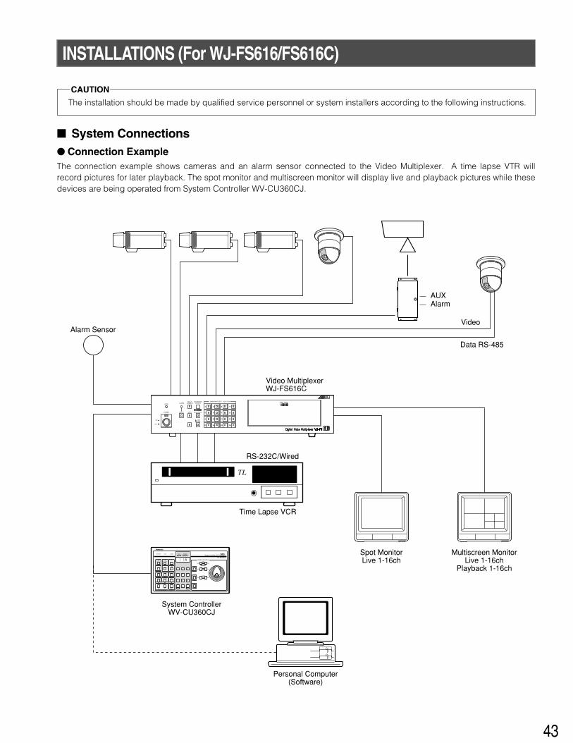
� Front View (Template for WJ-FS616C) ....................... 40INSTALLATIONS (For WJ-FS616/FS616C) ....................... 43
� System Connections .................................................. 43� DIP Switch Setting (For Multiplexer) ........................... 44� Controller Number Setting ......................................... 45
SETUP PROCEDURES (For WJ-FS616/FS616C) .............. 46� Prior to Setup ............................................................. 46� Buttons and Controls Used for Setup ........................ 46� Controller Setup ......................................................... 47
OPERATING PROCEDURES (For WJ-FS616/FS616C) .... 49� Camera Selection ....................................................... 49� Camera Control .......................................................... 49� Alarm Operation ......................................................... 50� VTR (VCR) Control ..................................................... 50� Camera Setup ............................................................ 51
Chapter 3 For System 850 WJ-SX850 Matrix Switcher System ... 53MAJOR OPERATING CONTROLS & THEIR FUNCTIONS .... 54
� Front View (Template for System 850Matrix Switcher) ......................................................... 54
INSTALLATIONS (For System 850) .................................. 58� System Connections .................................................. 58� DIP Switch Setting ...................................................... 60� Controller Number Setting ......................................... 60
SETUP PROCEDURES (For System 850) ......................... 61� Prior to Setup ............................................................. 61� Buttons and Controls Used for Setup ........................ 61� Setup Procedures ...................................................... 62
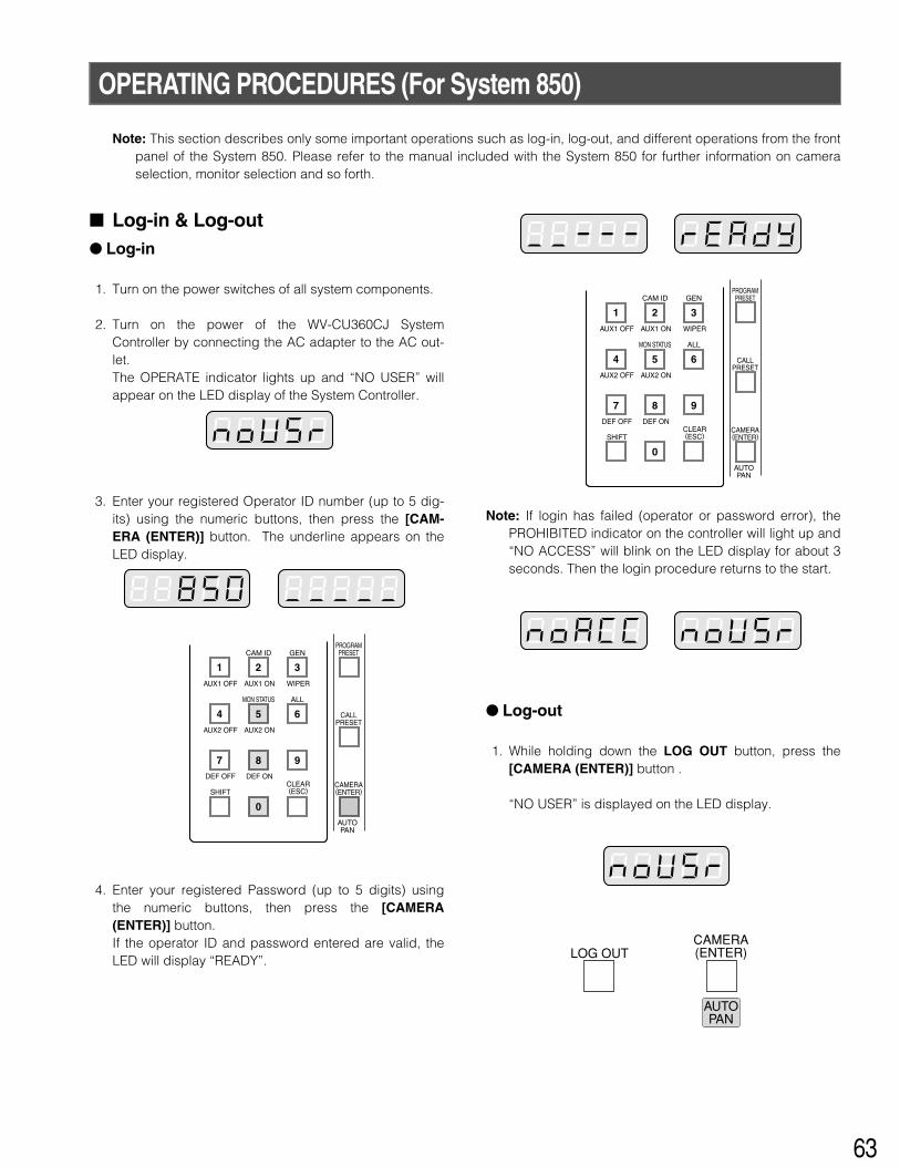
The System Controller WV-CU360CJ is designed for setupand operation of cameras and other system units installedin a surveillance system.The controller is compatible with the Panasonic SecurityData (PS •Data) protocol by default, but DIP switches areprovided to select the conventional communication protocolused with the Video Multiplexer WJ-FS616C or MatrixSwitcher WJ-SX850. Exchangeable templates are supplied
to adapt the names printed on the buttons to the functionsof the unit you wish to control.You can operate a whole system from the controller, forexample, by selecting cameras and monitors, watchingmonitor screens and indicators, and controlling pan/tilt, lensand other camera functions.
FEATURES
Main features• Camera channel selection • Monitor Selection • Alarm (Display/Suspend/Recall/Reset)• Camera and system unit setup
Sequence/Random Pan/Preset/Home/Camera Patrol• Single-handed control of pan/tilt, zoom, and auto focus
functions
In a PS •Data or a WJ-FS616 system• Switching of Live pictures and Playback/Changing the
Multiscreen Picture layout/Electronic Zoom/Sequence• System Unit Selection
PRECAUTIONS
• Refer all work related to the installation of thisproduct to qualified service personnel or systeminstallers.
• Do not attempt to disassemble the appliance.To prevent electric shock, do not remove screws orcovers.There are no user-serviceable parts inside. Contactqualified service personnel for maintenance.
• Handle the appliance with care.Do not strike or shake, as this may damage the appli-ance.
• Do not expose the appliance to water or moisture,nor try to operate it in wet areas.Take immediate action if the appliance becomes wet.Turn the power off and refer servicing to qualified ser-vice personnel. Moisture may damage the applianceand cause electric shock.
• Do not use strong or abrasive detergents whencleaning the appliance body.Use a dry cloth to clean the appliance when it is dirty.When the dirt is hard to remove, use a mild detergentand wipe gently.
• Do not operate the appliance beyond its specifiedtemperature, humidity or power source ratings.Do not use in the appliance in an extreme environmentwhere high temperature or high humidity exists.Use the appliance at temperatures within –10˚C to+50˚C (14˚F to 122˚F) and a humidity below 90 %. Theinput power source for this appliance is 220 V to 240 VAC 50 Hz by use of the AC Adapter supplied.
• Do not use any AC adapter other than the onesupplied.Be sure to use the supplied power cable. Any cableother than the supplied power cable is not usable. Thesupplied power cable cannot be used with any otherequipment.
5
MAJOR OPERATING CONTROLS & THEIR FUNCTIONS
� Rear View & AC Adapter
DC 9V INDATAMODE
RISK OF ELECTRIC SHOCK. DO NOT OPEN
RISQUE DE CHOCS ELECTROUESNE PAS OUVRIR
09
87 6 5 4
321
r te
CONTROLLER No.
wq
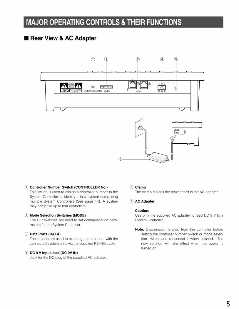
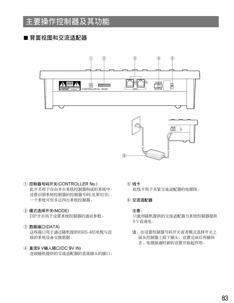
q Controller Number Switch (CONTROLLER No.)This switch is used to assign a controller number to theSystem Controller to identify it in a system comprisingmultiple System Controllers (See page 14). A systemmay comprise up to four controllers.
w Mode Selection Switches (MODE)The DIP switches are used to set communication para-meters for the System Controller.
e Data Ports (DATA)These ports are used to exchange control data with theconnected system units via the supplied RS-485 cable.
r DC 9 V Input Jack (DC 9V IN)Jack for the DC plug of the supplied AC adapter.
t ClampThe clamp fastens the power cord to the AC adapter.
y AC Adapter
Caution:Use only the supplied AC adapter to feed DC 9 V to aSystem Controller.
Note: Disconnect the plug from the controller beforesetting the controller number switch or mode selec-tion switch, and reconnect it when finished. Thenew settings will take effect when the power isturned on.
DC 9V IN
y
6
INSTALLATIONS
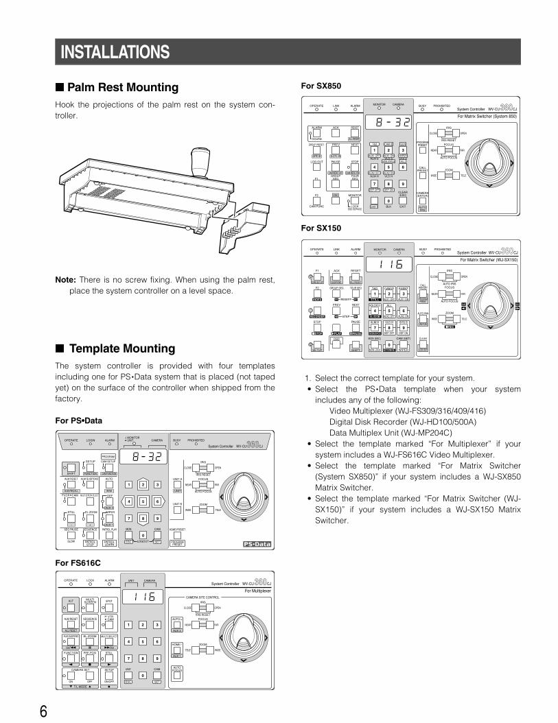
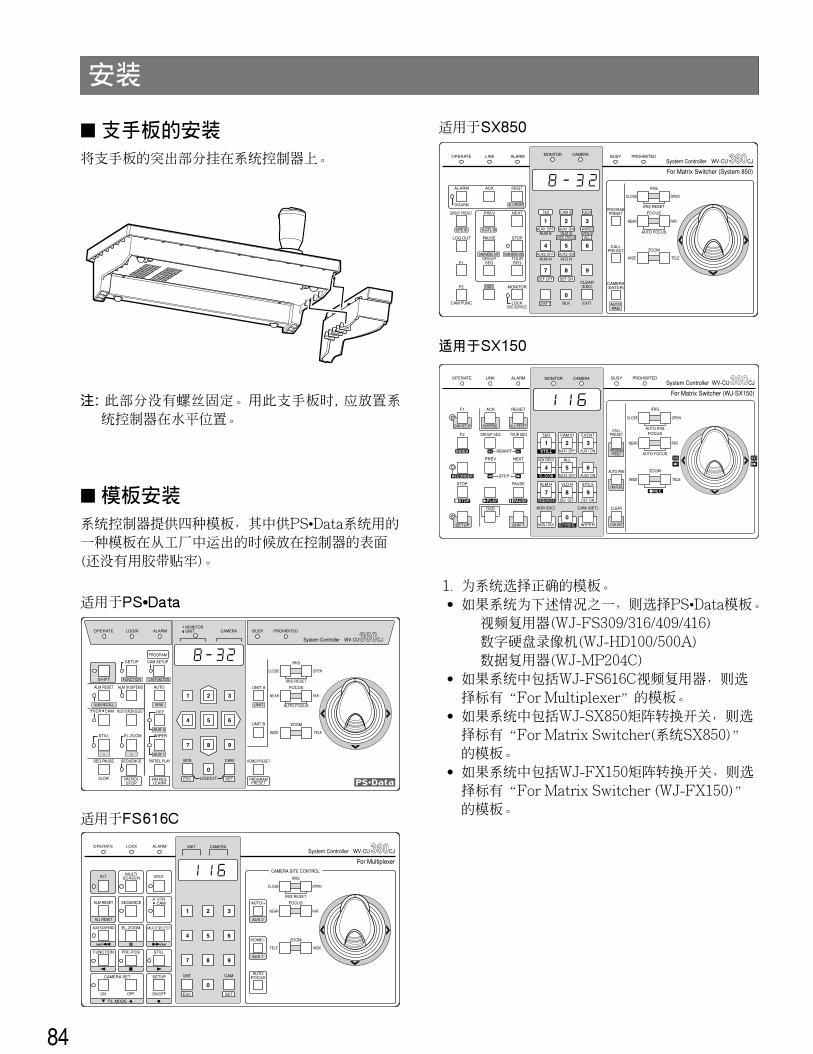
� Template MountingThe system controller is provided with four templatesincluding one for PS •Data system that is placed (not tapedyet) on the surface of the controller when shipped from thefactory.
1. Select the correct template for your system.• Select the PS •Data template when your system
includes any of the following:Video Multiplexer (WJ-FS309/316/409/416)Digital Disk Recorder (WJ-HD100/500A)Data Multiplex Unit (WJ-MP204C)
• Select the template marked “For Multiplexer” if yoursystem includes a WJ-FS616C Video Multiplexer.
• Select the template marked “For Matrix Switcher(System SX850)” if your system includes a WJ-SX850Matrix Switcher.
• Select the template marked “For Matrix Switcher (WJ-SX150)” if your system includes a WJ-SX150 MatrixSwitcher.
OPERATE LOGIN ALARM
CAM SETUP
PROGRAM
PROGRAMPRESET
UNIT A
IRIS
CLOSE OPEN
NEAR FAR
WIDE TELE
FOCUS
ZOOM
AUTO FOCUS
IRIS RESET
AUTO
SETUP
ALM SUSPEND
FUNCTION CAM FUNCTION
MULTI SCREEN SELECT DEF
WIPEREL-ZOOM
SHIFT
ALM RESET
VCR CAM
STILL
– +
ALM RECALL
PATROLLEARN
PATROLSTOP
AUX 1
AUX 2
B/W UNIT
SEQ PAUSE
SLOW
SEQUENCE PATROL PLAY HOME/PRESET
UNIT B
MON CAM
LOGOUTESC SET
BUSY PROHIBITEDMONITORUNIT CAMERA
System Controller WV-CU CJ360
AUTO FOCUS
OPERATE LINK ALARM BUSY PROHIBITED
IRIS
CLOSE OPEN
NEAR FAR
WIDE TELE
FOCUS
ZOOM
IRIS RESET
PREV
SEQSEQTOURGROUP
ALARM
DISARM
ACK RESET
GROUP PRESET NEXT
LOG OUT PAUSE STOP
F1
F2 MONITOR
CAM FUNC LOCKOSD SERVICE
CAMERA(ENTER)
CLEAR(ESC)
CALLPRESET
PROGRAMPRESET
SHIFT
DEF OFF DEF ON
AUX2 OFF AUX2 ON
AUX1 OFF AUX1 ON
CAM IDT&D
OPE ID S-CTL ID
OSD
CAM MENU OFF CAM MENU ON
ALL RESET
MDN STATUS
WIPER
GEN
ALL
EXITBLK
VLD HALM H
VLD S SYS SALM S
AUTOPAN
For Matrix Switcher (System 850)
WV-CU CJ360System ControllerMONITOR CAMERA
System ControllerOPERATE LOCK ALARM
SPOT
AUTO/+
IRIS
CLOSE OPEN
NEAR FAR
TELE WIDE
FOCUS
ZOOM
IRIS RESETVTRCAM
MULTISCREEN
SEQUENCE
EL-ZOOM MULTI SELECT
STILLPRE-POSI
ALT
ALM RESET
ALM SUSPEND
FUNCTION
ALL RESET
CAMERA SET
ON OFF ON/OFF
SETUPAUTO
FOCUS
HOME/-
UNIT CAM
ESC SET
UNIT CAMERA
For Multiplexer
WV-CU CJ360
T/L MODE
CAMERA SITE CONTROL
AUX 2
AUX 1
SETUP SHIFT
REW/FF
STEP
AUTO FOCUS
OPERATE LINK ALARM BUSY PROHIBITED
CALLPRESET
PROGRAMPRESET
IRIS
CLOSE OPEN
NEAR FAR
WIDE TELE
FOCUS
ZOOM
AUTO IRIS
GROUP SEQ
PAUSE
SUSPEND
F1
CAM SETUP ALL RESET
ACK RESET
F2 TOUR SEQ
PREV NEXT
STOP
OSD
AUTO PAN
MONITOR CAMERA
For Matrix Switcher (WJ-SX150)
WV-CU CJ360System Controller
RECORDER
INDEX
STOP PLAY
REC
PAUSE
CAM FUNC
CLEAR
LOG OUTMON LOCK
DEF ON
WIPER
DEF OFF
MON (ESC)
T&D CAM ID
MON STATUS ALL
EVENT
ALM H VLD H SYS S
CAM (SET)
MULTI SCREEN SEL
SEQUENCE
AUX2 ONAUX2 OFFEL-ZOOM
AUX1 ONAUX1 OFFSTILL
For PS•Data
For FS616C
For SX850
For SX150
� Palm Rest MountingHook the projections of the palm rest on the system con-troller.
Note: There is no screw fixing. When using the palm rest,place the system controller on a level space.
7
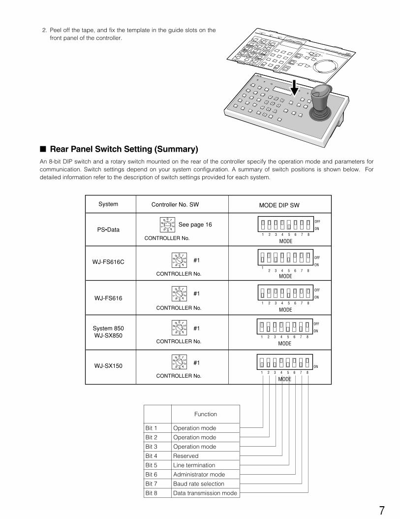
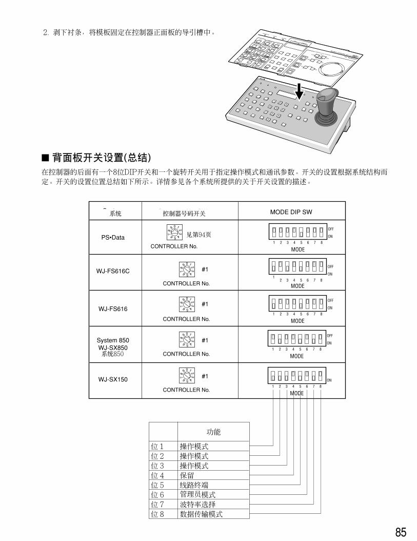
2. Peel off the tape, and fix the template in the guide slots on thefront panel of the controller.
� Rear Panel Switch Setting (Summary)An 8-bit DIP switch and a rotary switch mounted on the rear of the controller specify the operation mode and parameters forcommunication. Switch settings depend on your system configuration. A summary of switch positions is shown below. Fordetailed information refer to the description of switch settings provided for each system.
MODE1 2 3 4 5 6 7 8
OFF
ON
09
87 6 5 4
321
CONTROLLER No.
System Controller No. SW MODE DIP SW
PS•Data
MODE
12 3 4 5 6 7 8
OFF
ONWJ-FS616C
MODE1 2 3 4 5 6 7 8
OFF
ON
CONTROLLER No.
WJ-FS616
MODE1 2 3 4 5 6 7 8
OFF
ON
MODE1 2 3 4 5 6 7 8
ON
CONTROLLER No.
System 850WJ-SX850
WJ-SX150
09
87 6 5 4
321
CONTROLLER No.
#1
#1
#109
87 6 5 4
321
CONTROLLER No.
#109
87 6 5 4
321
09
87 6 5 4
321
See page 16
Function
Bit 3
Bit 2
Bit 1
Bit 4
Bit 5
Bit 6
Bit 7
Bit 8
Operation mode
Operation mode
Operation mode
Reserved
Line termination
Administrator mode
Baud rate selection
Data transmission mode
89
7
0
45
6
23
1
OPERATELOCK
ALARM
AUTO/+
IRISCLOSE
OPENNEAR
FAR
TELE
WIDE
FOCUS
ZOOM
SPOT
MULTI SELECT
VTRCAM
ALT
FUNCTION
ALM RESET
ALM SUSPEND
ALL RESET
SEQUENCE
PRE-POSI
EL-ZOOM
MULTISCREEN
IRIS RESETCAMERA SET
SET UP
STILL
ON/OFF
OFF
ON
AUTOFOCUS
HOME/-UNIT
CAMESC
SET
CAMERA SITE CONTRIL
CAMERA
UNIT
System ControllerFor Multiplexer
WV-CU CJ AUX 2
AUX 1
T/L MODE
8
9
For Panasonic SecurityData (PS •Data) Systems
10
MAJOR OPERATING CONTROLS & THEIR FUNCTIONS
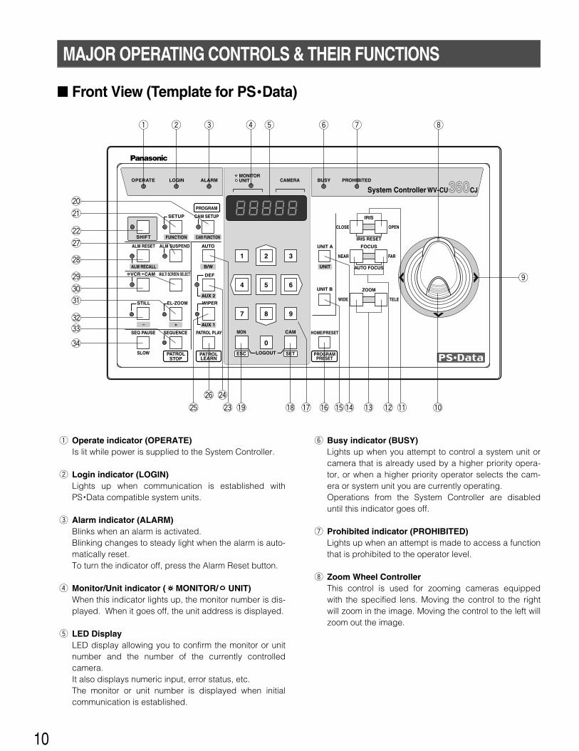
� Front View (Template for PS •Data)
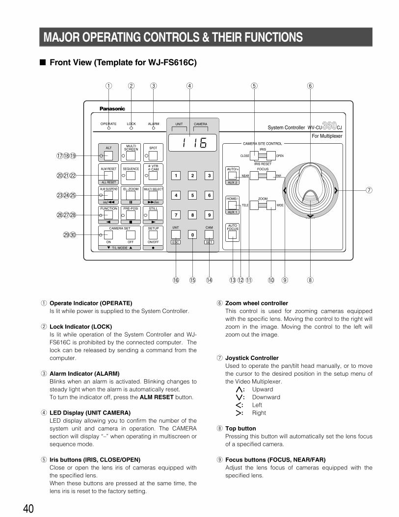
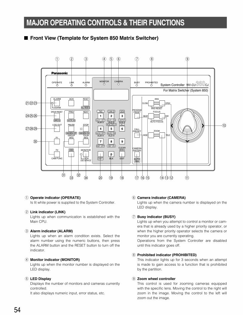
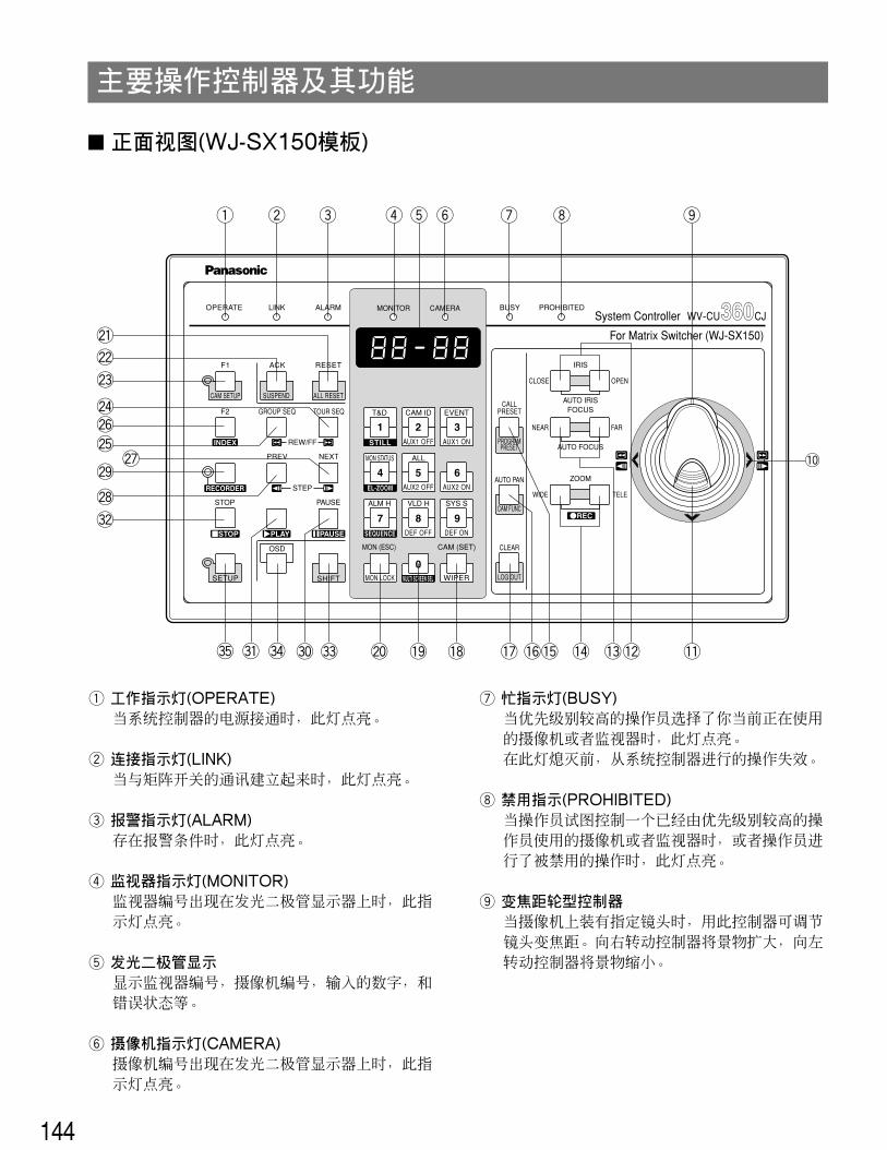
q Operate indicator (OPERATE)Is lit while power is supplied to the System Controller.
w Login indicator (LOGIN)Lights up when communication is established withPS •Data compatible system units.
e Alarm indicator (ALARM)Blinks when an alarm is activated.Blinking changes to steady light when the alarm is auto-matically reset.To turn the indicator off, press the Alarm Reset button.
r Monitor/Unit indicator ( MONITOR/ UNIT)When this indicator lights up, the monitor number is dis-played. When it goes off, the unit address is displayed.
t LED DisplayLED display allowing you to confirm the monitor or unitnumber and the number of the currently controlledcamera. It also displays numeric input, error status, etc.The monitor or unit number is displayed when initialcommunication is established.
y Busy indicator (BUSY)Lights up when you attempt to control a system unit orcamera that is already used by a higher priority opera-tor, or when a higher priority operator selects the cam-era or system unit you are currently operating.Operations from the System Controller are disableduntil this indicator goes off.
u Prohibited indicator (PROHIBITED)Lights up when an attempt is made to access a functionthat is prohibited to the operator level.
i Zoom Wheel ControllerThis control is used for zooming cameras equippedwith the specified lens. Moving the control to the rightwill zoom in the image. Moving the control to the left willzoom out the image.
OPERATE LOGIN ALARM
CAM SETUP
PROGRAM
PROGRAMPRESET
UNIT A
IRIS
CLOSE OPEN
NEAR FAR
WIDE TELE
FOCUS
ZOOM
AUTO FOCUS
IRIS RESET
AUTO
SETUP
ALM SUSPEND
FUNCTION CAM FUNCTION
MULTI SCREEN SELECT DEF
WIPEREL-ZOOM
SHIFT
ALM RESET
VCR CAM
STILL
– +
ALM RECALL
PATROLLEARN
PATROLSTOP
AUX 1
AUX 2
B/W UNIT
SEQ PAUSE
SLOW
SEQUENCE PATROL PLAY HOME/PRESET
UNIT B
MON CAM
LOGOUTESC SET
BUSY PROHIBITEDMONITORUNIT CAMERA
System Controller WV-CU CJ360
@8
@7
@2
@0
@1
@9
#2
#1
#0
wq e r t y u i
o
!3 !0!2 !1!6!7!8!9@5
@6
!5!4@3
@4
#4
#3
11
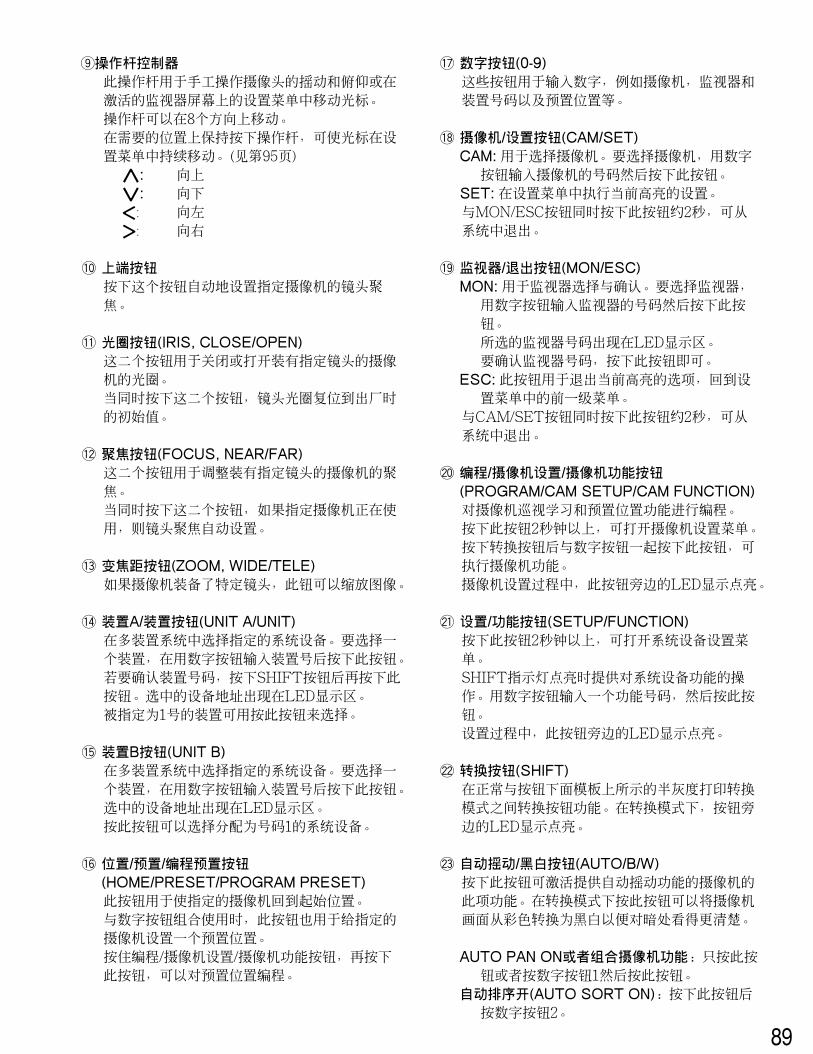
o Joystick ControllerUsed to manually operate the pan/tilt head, or move thecursor in the setup menu on the active monitor screen.The joystick can also be moved in 8 directions.Holding down the joystick in the desired position willkeep the cursor moving continuously in the setup menu.(See page 17.)
}: Upward{: Downward]: Left[: Right
!0 Top buttonPressing this button will automatically set the lens focusof a specified camera.
!1 Iris buttons (IRIS, CLOSE/OPEN)Close or open the lens iris of cameras equipped withthe specified lens.When these buttons are pressed simultaneously, thelens iris is reset to the factory default setting.
!2 Focus buttons (FOCUS, NEAR/FAR)Adjust the lens focus of cameras equipped with thespecified lens.When these buttons are pressed simultaneously, thelens focus is set automatically if the specified camera isused.
!3 Zoom buttons (ZOOM, WIDE/TELE)Zoom the image in or out if the camera is equipped withthe specified lens.
!4 Unit A/UNIT button (UNIT A/UNIT)Selects a specific system unit in a multiple unit system.To select a unit, press this button after entering the unitnumber with the numeric button. To confirm a unit num-ber, press this button after pressing the SHIFT button.The selected unit address appears on the LED display.The unit that is assigned to number 1 can be selectedby pressing this button.
!5 Unit B button (UNIT B)Selects a specific system unit in a multiple unit system.To select a unit, press this button after entered the unitnumber with the numeric button. The selected unitaddress appears on the LED display.Just pressing this button will select the system unitassigned the number 1.
!6 Home/Preset/Program Preset button(HOME/PRESET/PROGRAM PRESET)Returns a specific camera to its home position.In combination with the numeric buttons, this button isalso used to recall a preset position assigned to a spe-cific camera.Pressing it while holding down the Program/CameraSetup/Camera Function button will program the presetposition.
!7 Numeric buttons (0-9)These buttons are used for numeric input, such as cam-era, monitor and unit numbers, and preset positions.
!8 Camera/Set button (CAM/SET)CAM: Used for camera selection. To select a camera,
enter the desired camera number with the numericbuttons, and then press this button.
SET: Executes the currently highlighted setting in thesetup menu.
Pressing this button together with the MON/ESC buttonfor approximately 2 seconds will log out from the sys-tem.
!9 Monitor/Escape button (MON/ESC)MON: Used for monitor selection and confirmation. To
select a monitor, enter the desired monitor numberwith the numeric buttons, and then press this but-ton. The selected monitor number appears on theLED display.To confirm a monitor number, simply press this but-ton.
ESC: Used to escape from the currently highlightedselection and return to the previous menu of thesetup menu.
Pressing this button together with the CAM/SET buttonfor approximately 2 seconds will log out from the sys-tem.
@0 Program/Camera Setup/Camera Function button(PROGRAM/CAM SETUP/CAM FUNCTION)Programs camera patrol learning and preset positionfunctions.Pressing this button for 2 seconds or more will open thecamera setup menu. Pressing it in combination with thenumeric buttons after pressing the shift button will exe-cute camera functions. The LED next to the button is lit during the camerasetup operation.
@1 Setup/Function button (SETUP/FUNCTION)Pressing this button for 2 seconds or more will open thesetup menu of a system unit. When the SHIFT indicator is lit, it provides access to thefunctions of the system unit. Enter a function numberwith the numeric keys, then press this button.The LED next to the button is lit during the setup opera-tion.
@2 Shift button (SHIFT)Shifts the button function between the normal and theshift mode shown in half-tone print under the button onthe template. The LED next to the button is lit in theshift mode.
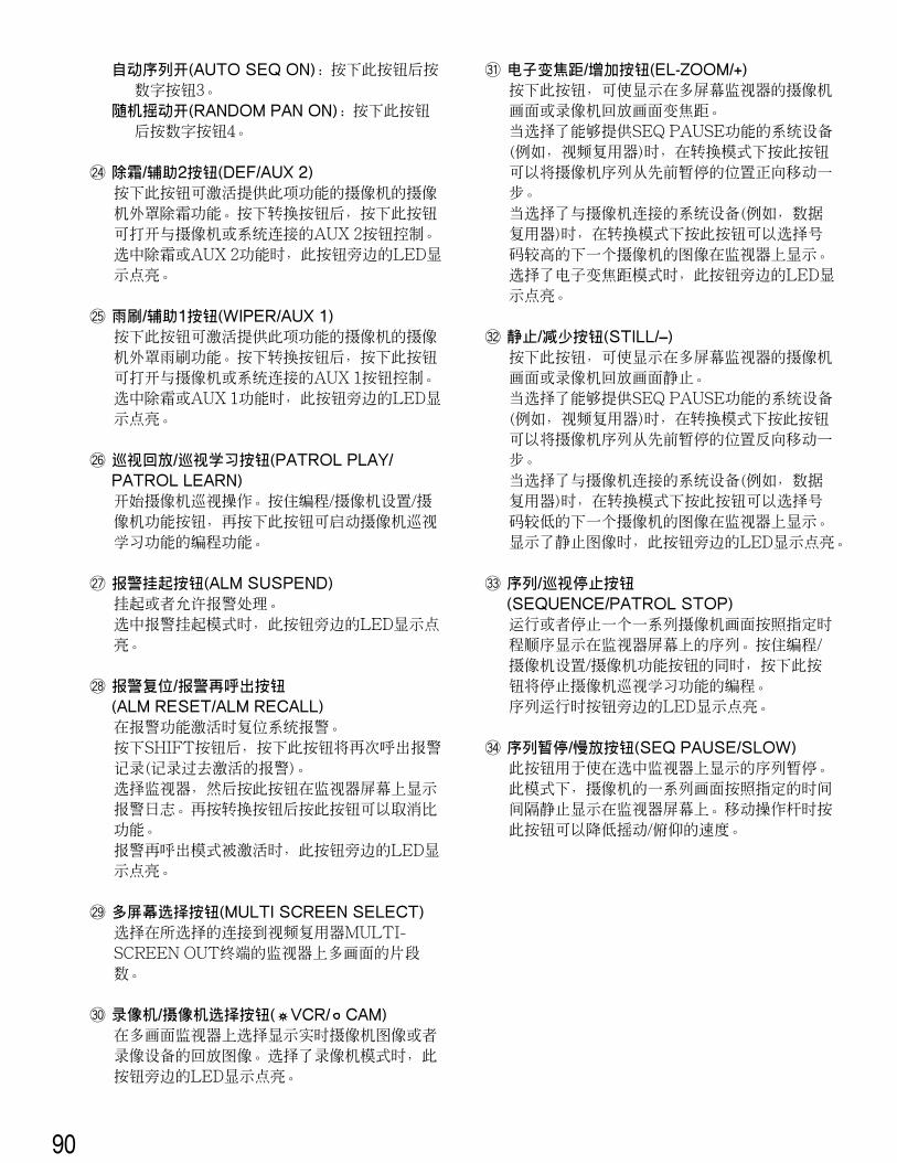
@3 Auto Panning/Black and White button (AUTO/B/W)Activates the auto panning function of cameras provid-ed with this feature. Pressing this button in the shiftmode will change the camera picture from colour toblack and white for better viewing in a dark place.
12
AUTO PAN ON or combination camera function:Simply press this button, or press numeric button 1followed by this button.
AUTO SORT ON: Press numeric button 2 followed bythis button.
AUTO SEQ ON: Press numeric button 3 followed bythis button.
RANDOM PAN ON: Press numeric button 4 followed bythis button.
@4 Defroster/Auxiliary 2 button (DEF/AUX 2)Activates the housing defroster of cameras providedwith this feature. Pressing this button in the shift modewill turn on the AUX 2 function controlling accessoriesconnected to the cameras or the system.The LED next to the button is lit while the defroster orAUX 2 function operates.
@5 Wiper/Auxiliary 1 button (WIPER/AUX 1)Activates the housing wiper of cameras provided withthis feature. Pressing this button in the shift mode willturn on the AUX 1 function controlling accessories con-nected to the cameras or the system.The LED next to the button is lit while the wiper or AUX1 function operates.
@6 Patrol Play/Patrol Learn button (PATROL PLAY/PATROL LEARN)Starts the camera patrol play. While holding down theProgram/Camera setup/Camera Function button, press-ing this button will start to program the camera patrollearning.
@7 Alarm Suspend button (ALM SUSPEND)Suspends or allows the alarm process.The LED next to the button is lit while the alarm suspen-sion mode operates.
@8 Alarm Reset/Alarm Recall button (ALM RESET/ALMRECALL)Resets system alarm when the alarm function is active.Pressing this button in the SHIFT mode will recall thealarm logs (record of alarms activated in the past).Select a monitor, and then press this button to displaythe alarm logs on the monitor screen. Pressing this but-ton after pressing the shift button again will cancel thefunction. The LED next to the button is lit while Alarm Recallmode is activated.
@9 Multiscreen Selection button (MULTI SCREENSELECT)Selects the number of segments into which the multi-screen is split on the selected monitor connected to theMULTISCREEN OUT terminal of the Video Multiplexer.
#0 VTR/Camera Selection button ( VCR/ CAM)Changes the display on the multiscreen monitorbetween the live picture of a camera and the playbackpicture of a recording device. The LED next to the but-ton is lit while VCR is selected.
#1 Electronic Zoom/Increment button (EL-ZOOM/+)Zooms the camera picture or VCR playback picture dis-played on the multiscreen monitor.Pressing this button in the shift mode will move thecamera sequence one step forward from the step previ-ously paused while a system unit provided with SEQPAUSE (e.g., a Video Multiplexer) is selected.Pressing this button in the shift mode will select the pic-ture of camera with the next higher number for displayon the monitor while a system unit connected with cam-eras (e.g., a Data Multiplex Unit) is selected.The LED next to the button is lit while Electronic Zoommode is selected.
#2 Still/Decrement button (STILL/–)Freezes the camera picture or VCR playback picture onthe multiscreen monitor.Pressing this button in the shift mode will move thecamera sequence one step backward from the steppreviously paused while a system unit (e.g., a VideoMultiplexer) provided with SEQ PAUSE is selected.Pressing this button in the shift mode will select the pic-ture of the camera with the next lower number for dis-play on the monitor while a system unit connected withcameras (e.g., a Data Multiplex Unit) is selected.The LED next to the button is lit while a still picture isdisplayed.
#3 Sequence/Patrol Stop button (SEQUENCE/PATROLSTOP)Runs or stops a preset sequence in which a series ofcamera pictures is displayed in succession on the mon-itor screen for the specified duration. Pressing it whileholding down the Program/Camera Setup/CameraFunction button will stop programming of camera patrollearning.The LED next to the button is lit while a sequence runs.
#4 Sequence Pause/Slow button (SEQ PAUSE/SLOW)Pauses a sequence running on the selected monitor. Inthis mode, a series of camera pictures is displayed inpause on the monitor screen for the specified duration.Pressing this button while moving the joystick controllerwill decrease the pan/tilt speed.
13
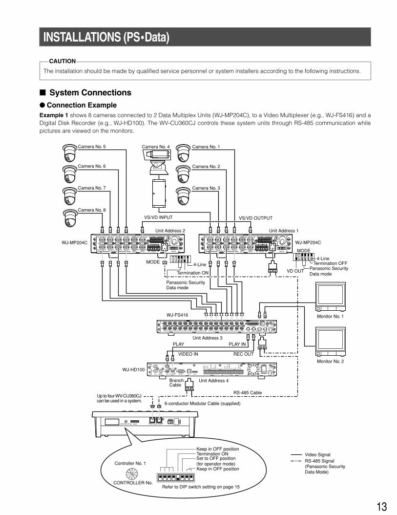
INSTALLATIONS (PS•Data)
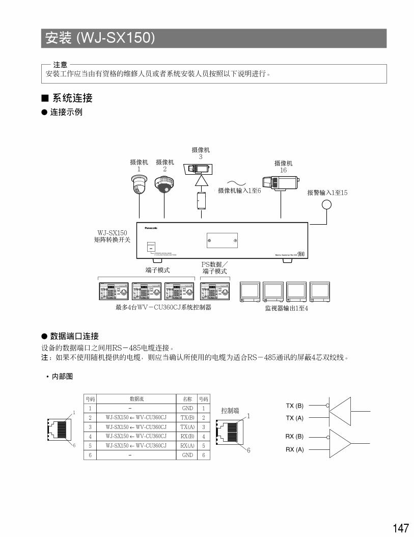
The installation should be made by qualified service personnel or system installers according to the following instructions.
CAUTION
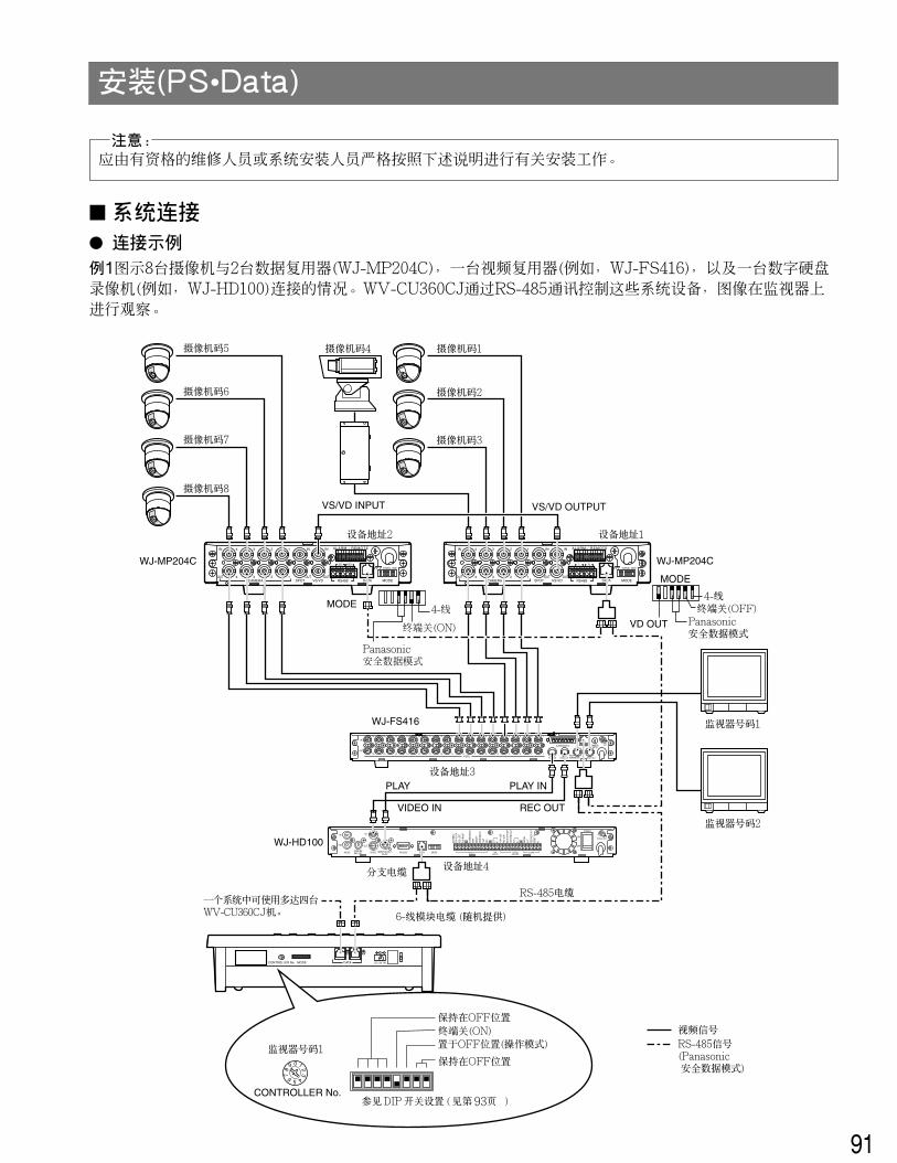
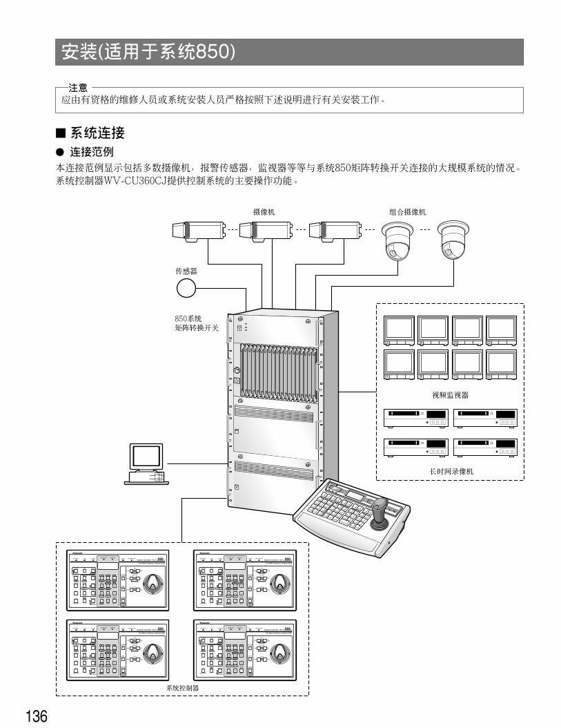
� System Connections� Connection ExampleExample 1 shows 8 cameras connected to 2 Data Multiplex Units (WJ-MP204C), to a Video Multiplexer (e.g., WJ-FS416) and aDigital Disk Recorder (e.g., WJ-HD100). The WV-CU360CJ controls these system units through RS-485 communication whilepictures are viewed on the monitors.
SIGNALGNDALARM/REMOTE
OUT
IN
VIDEO
16 15 14 13 12 11 10 9 8
16 15 14 13 12 11 10 9 8
7 6 5 4 2 1
7 6 5 4 3
3
2 1
PLAY IN REC OUT SPOT OUT
DATA CAMERASW IN
MULTISCREEN OUT
SD RD
IN IN
CAMERA RS485
ABABG
VS/VDSPOT DATA
ALARM / REMOTE
MODE
SIGNAL GND
4 3 2 1
OUT OUT
IN
OUT4 3 2 1
T R
IN IN
CAMERA RS485
ABABG
VS/VDSPOT DATA
ALARM / REMOTE
MODE
SIGNAL GND
4 3 2 1
OUT OUT
IN
OUT4 3 2 1
Camera No. 1
Camera No. 2
Camera No. 3
Camera No. 4Camera No. 5
Camera No. 6
Camera No. 7
Camera No. 8
VS/VD INPUT
Unit Address 1Unit Address 2
WJ-MP204CWJ-MP204C
WJ-FS416
WJ-HD100
Unit Address 3
Unit Address 4
Video Signal
6-conductor Modular Cable (supplied)
Termination ON
MODE
VS/VD OUTPUT
4-Line
Monitor No. 1
Monitor No. 2
Panasonic Security Data mode
Termination OFFPanasonic Security Data mode
4-Line
MODE
VD OUT
RS-485 Signal(Panasonic SecurityData Mode)
SIGNAL GND
ALARMSERIESRECORD
TIMEADJUST
REMOTEMODEDATARS-232CVIDEO
OUT
IN
OUT
IN
AUDIO MONITOR OUT(PLAY)
CAMERASW OUT
G G G
POWER
ON
OFF
JOG
-CLI
CKJO
G-L
EFT
JOG
-RIG
HT
ALAR
M S
EARC
HST
EPRE
W/F
FST
OP/
SETU
PPL
AYRE
C
OUT
PLAY
OUT
REC
OUT
AUTO
OFF
OUT
DISK
END
OUT
IN OUT
IN RECA
LL
(EXT
REC
)
OUT
RECO
VER
OUT
RESE
T IN
IN
PLAY INPLAY
VIDEO IN REC OUT
RS-485 Cable
BranchCable
Up to four WV-CU360CJcan be used in a system.
DC 9V INDATAMODECONTROLLER No.
09
87 6 5 4
321
09
87
6 5 4
32
1
Keep in OFF position
Keep in OFF position
Termination ONSet to OFF position(for operator mode)Controller No. 1
Refer to DIP switch setting on page 15CONTROLLER No.
14
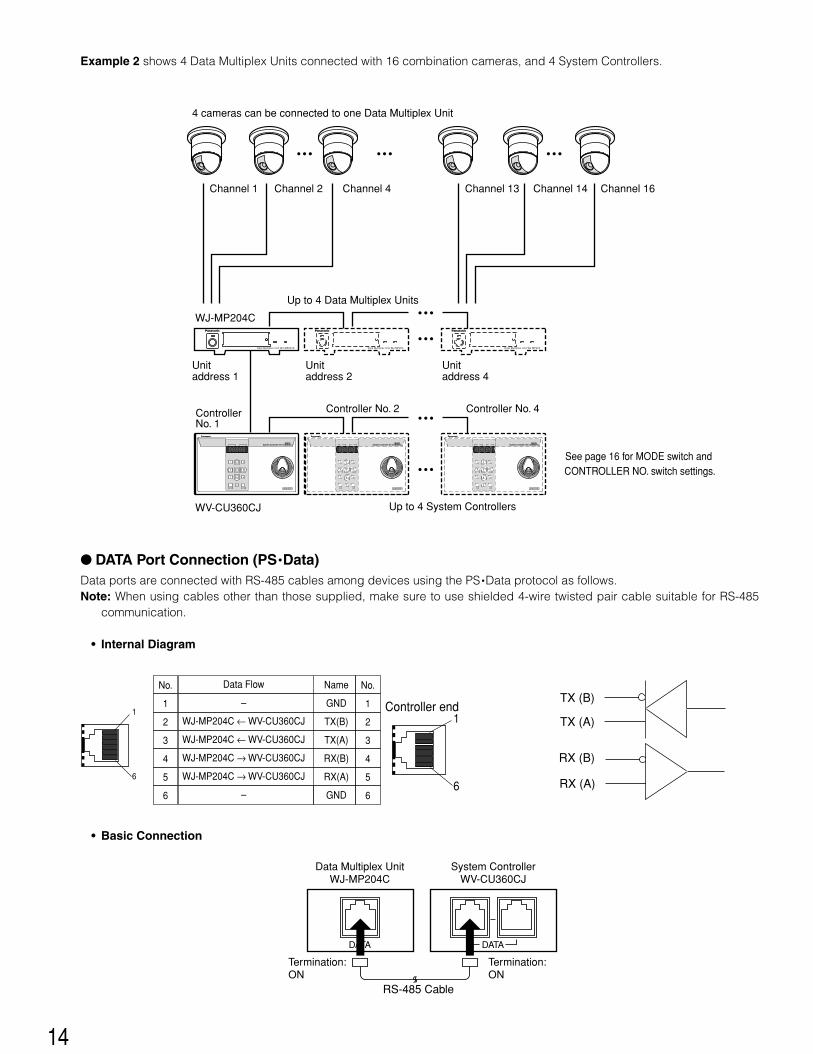
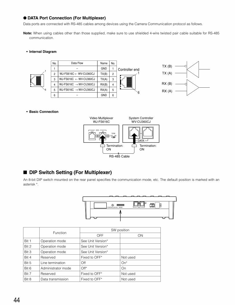
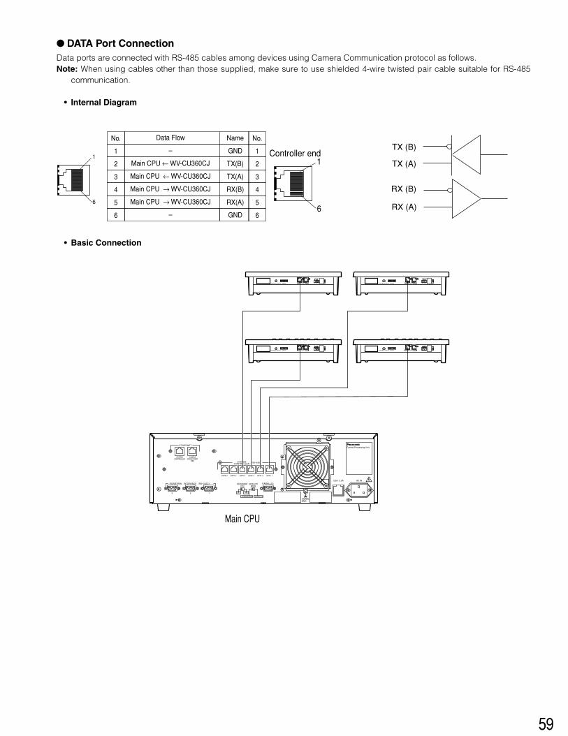
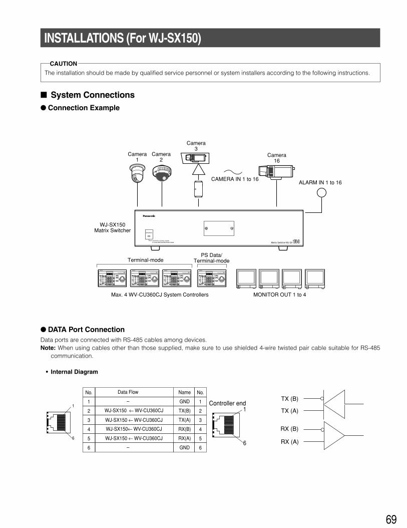
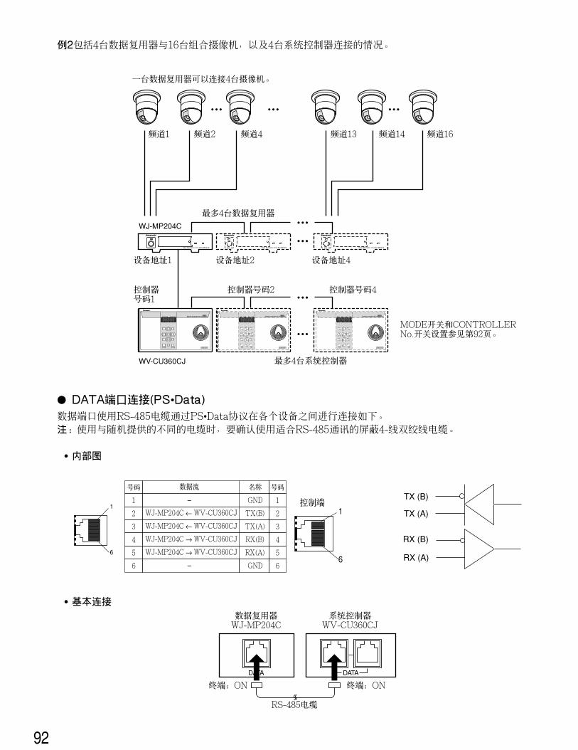
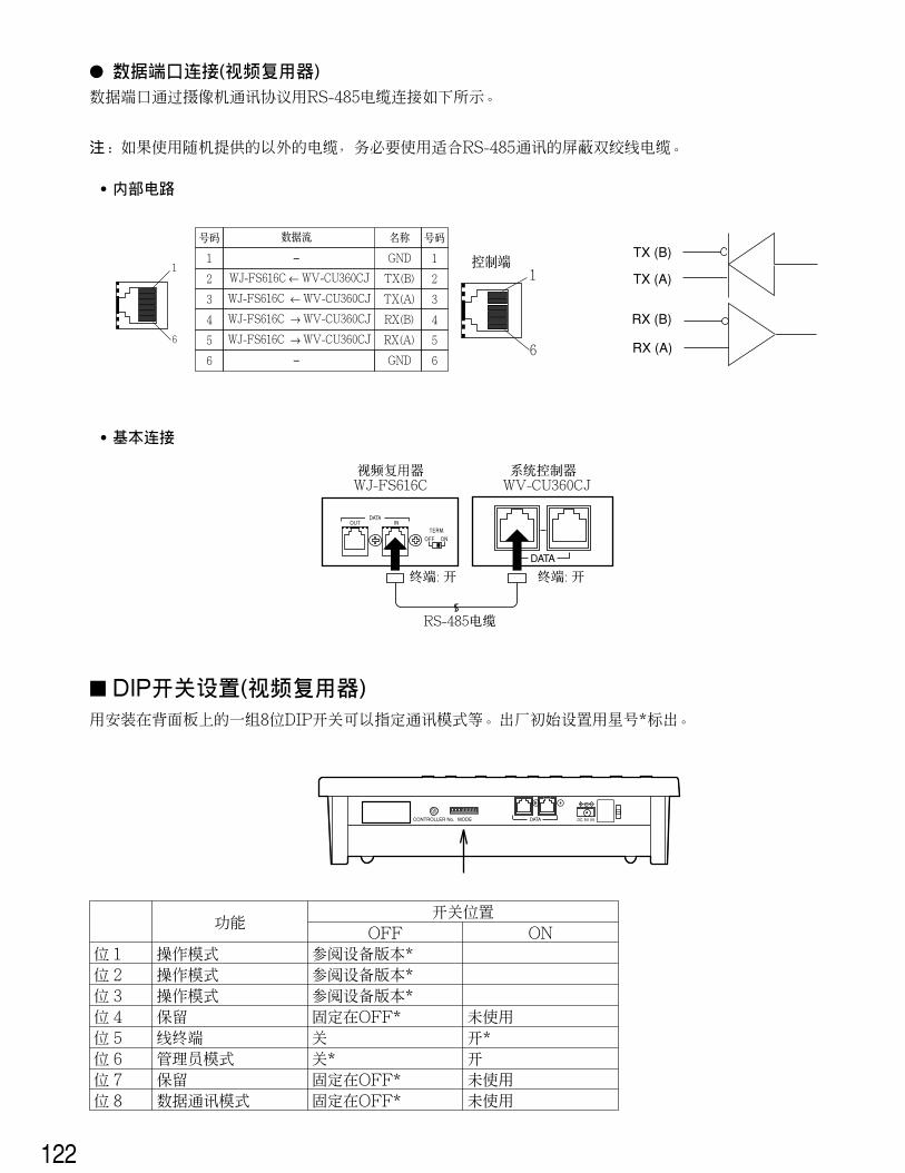
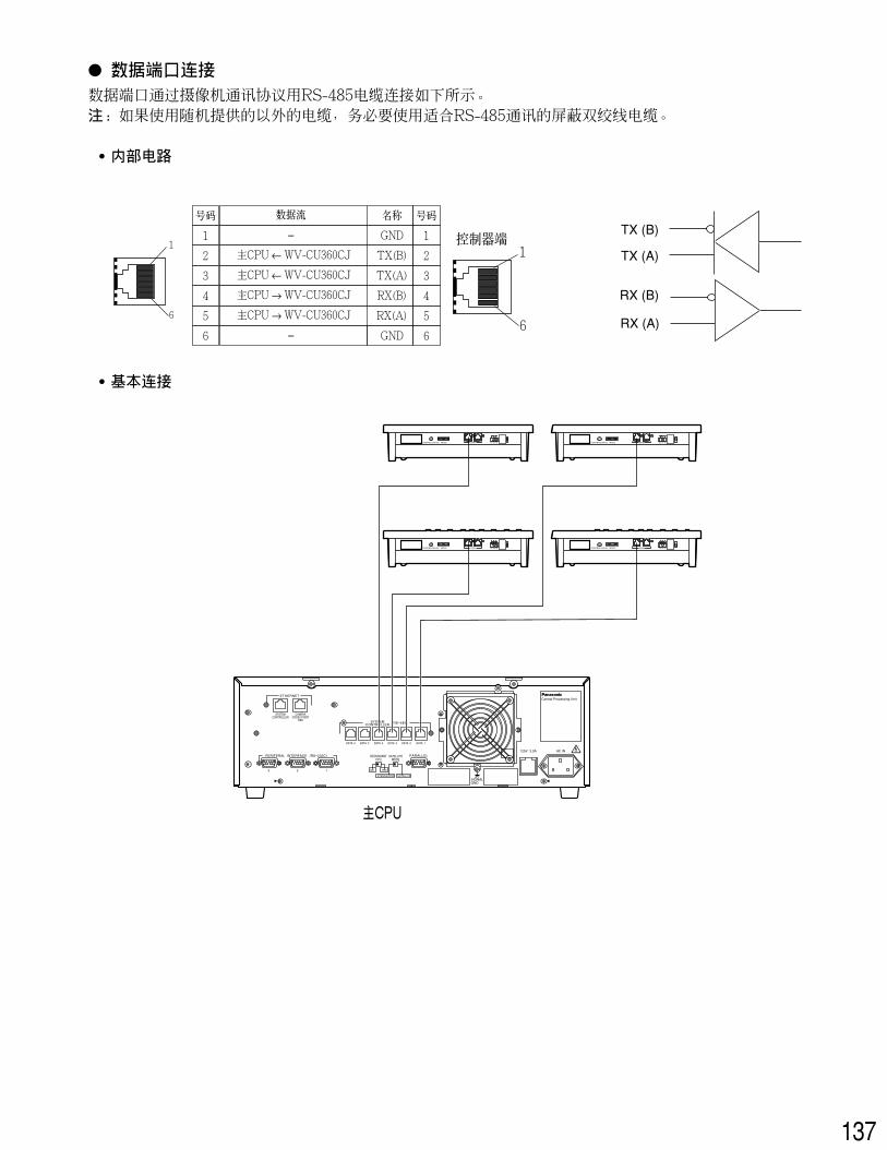
� DATA Port Connection (PS •Data)Data ports are connected with RS-485 cables among devices using the PS •Data protocol as follows.Note: When using cables other than those supplied, make sure to use shielded 4-wire twisted pair cable suitable for RS-485
communication.
• Internal Diagram
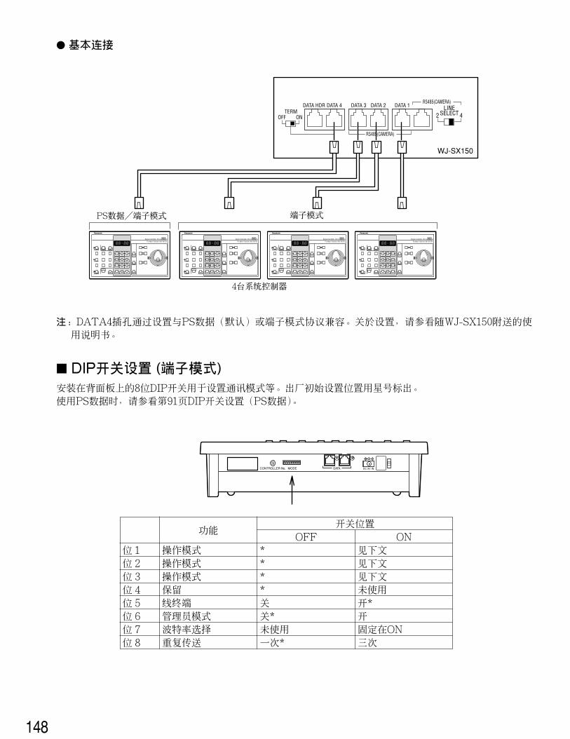
• Basic Connection
Example 2 shows 4 Data Multiplex Units connected with 16 combination cameras, and 4 System Controllers.
System Controller WV-CU CJ360
Data Multiplex Unit WJ-MP204C Data Multiplex Unit WJ-MP204 Data Multiplex Unit WJ-MP204
WJ-MP204C
WV-CU360CJ
4 cameras can be connected to one Data Multiplex Unit
System Controller WV-CU CJ360 System Controller WV-CU CJ360
See page 16 for MODE switch and CONTROLLER NO. switch settings.
DATA
Data Multiplex UnitWJ-MP204C
System ControllerWV-CU360CJ
DATA
RS-485 Cable
Termination:ON
Termination:ON
Data Flow
–
WJ-MP204C ← WV-CU360CJ
WJ-MP204C ← WV-CU360CJ
WJ-MP204C → WV-CU360CJ
WJ-MP204C → WV-CU360CJ
–
1
6
1
6
No. No.
1 1
2 2
3 3
4 4
5 5
6 6
Name
GND
TX(B)
TX(A)
RX(B)
RX(A)
GND
Controller endTX (B)
TX (A)
RX (A)
RX (B)
15
SW position
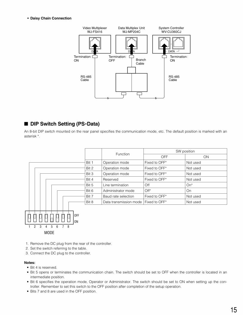
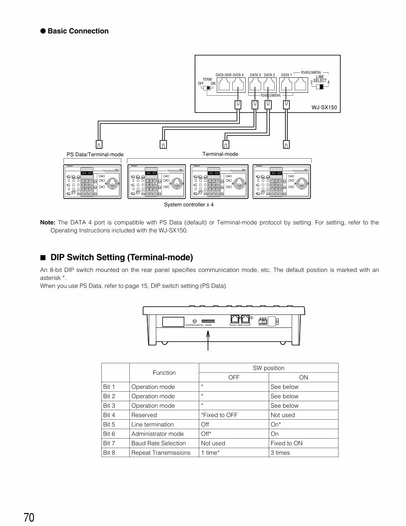
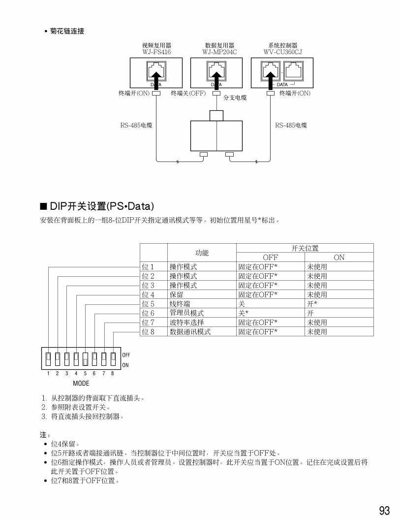
• Daisy Chain Connection
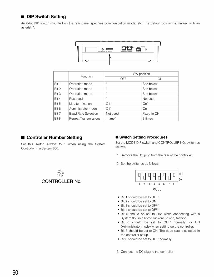
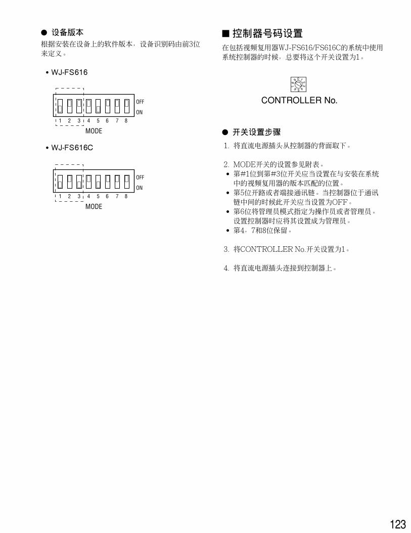
� DIP Switch Setting (PS •Data)An 8-bit DIP switch mounted on the rear panel specifies the communication mode, etc. The default position is marked with anasterisk *.
DATA
Data Multiplex UnitWJ-MP204C
BranchCable
Termination:OFF
Termination:ON
System ControllerWV-CU360CJ
DATA DATA
Video MultiplexerWJ-FS416
RS-485Cable
Termination:ON
RS-485Cable
MODE
1 2 3 4 5 6 7 8
OFF
ON
OFF
Not used
FunctionON
Bit 3
Bit 2
Bit 1
Bit 4
Bit 5
Bit 6
Bit 7
Bit 8
Operation mode
Operation mode
Operation mode
Reserved
Line termination
Administrator mode
Baud rate selection
Data transmission mode
Fixed to OFF*
Fixed to OFF*
Fixed to OFF*
Fixed to OFF*
Off
Off*
Fixed to OFF*
Fixed to OFF*
Not used
Not used
Not used
Not used
On*
On
Not used
1. Remove the DC plug from the rear of the controller.2. Set the switch referring to the table.3. Connect the DC plug to the controller.
Notes:• Bit 4 is reserved.• Bit 5 opens or terminates the communication chain. The switch should be set to OFF when the controller is located in an
intermediate position.• Bit 6 specifies the operation mode, Operator or Administrator. The switch should be set to ON when setting up the con-
troller. Remember to set this switch to the OFF position after completion of the setup operation.• Bits 7 and 8 are used in the OFF position.
16
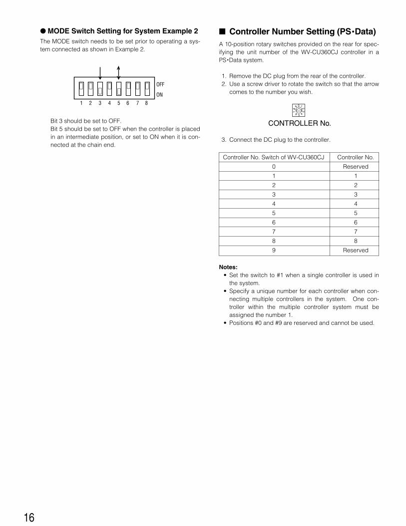
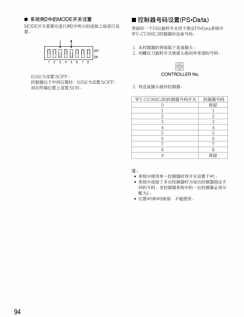
� MODE Switch Setting for System Example 2The MODE switch needs to be set prior to operating a sys-tem connected as shown in Example 2.
Bit 3 should be set to OFF.Bit 5 should be set to OFF when the controller is placedin an intermediate position, or set to ON when it is con-nected at the chain end.
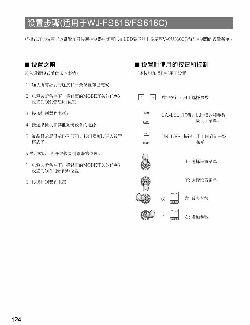
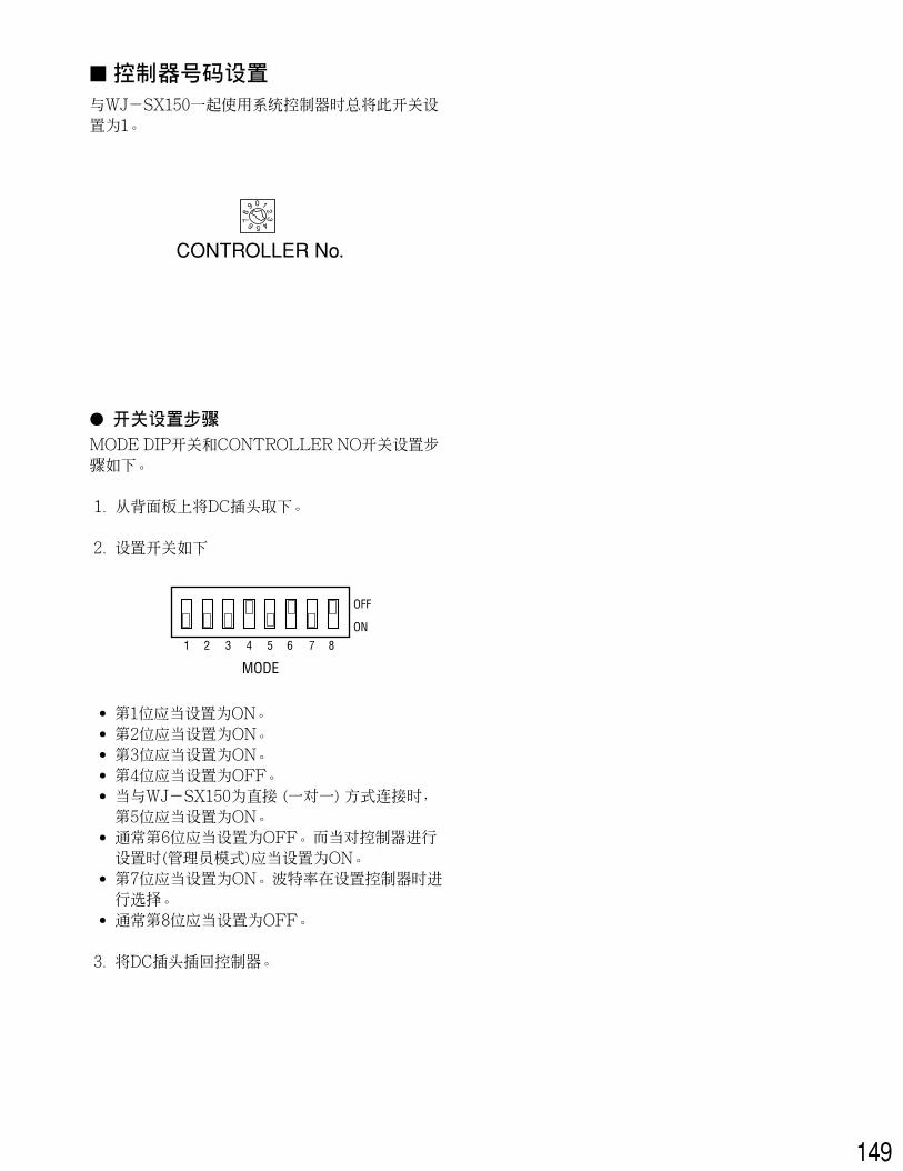
� Controller Number Setting (PS •Data)A 10-position rotary switches provided on the rear for spec-ifying the unit number of the WV-CU360CJ controller in aPS •Data system.
1. Remove the DC plug from the rear of the controller.2. Use a screw driver to rotate the switch so that the arrow
comes to the number you wish.
3. Connect the DC plug to the controller.
Notes:• Set the switch to #1 when a single controller is used in
the system.• Specify a unique number for each controller when con-
necting multiple controllers in the system. One con-troller within the multiple controller system must beassigned the number 1.
• Positions #0 and #9 are reserved and cannot be used.
09
87 6 5 4
321
CONTROLLER No.
Controller No. Switch of WV-CU360CJ Controller No.
0 Reserved
1 1
2 2
3 3
4 4
5 5
6 6
7 7
8 8
9 Reserved
1 2 3 4 5 6 7 8
OFF
ON
17
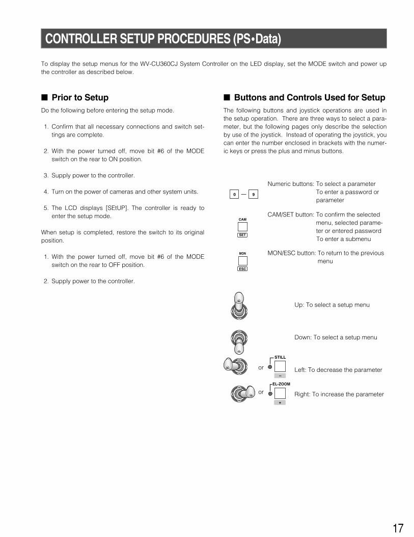
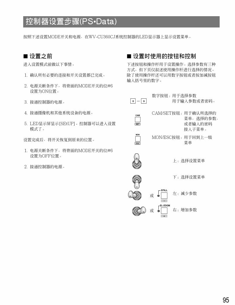
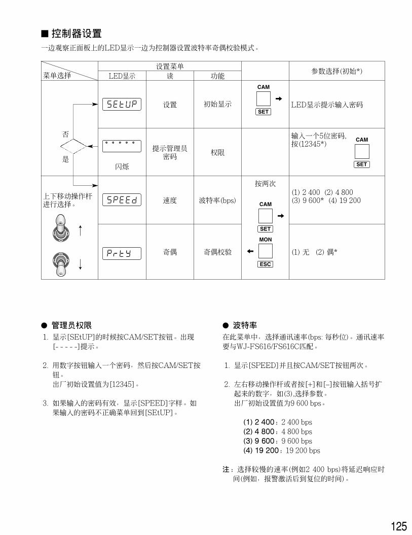
CONTROLLER SETUP PROCEDURES (PS•Data)
To display the setup menus for the WV-CU360CJ System Controller on the LED display, set the MODE switch and power upthe controller as described below.
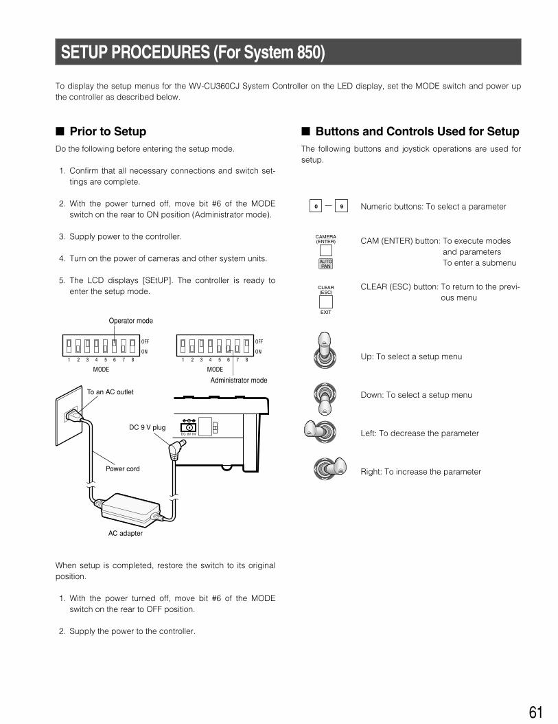
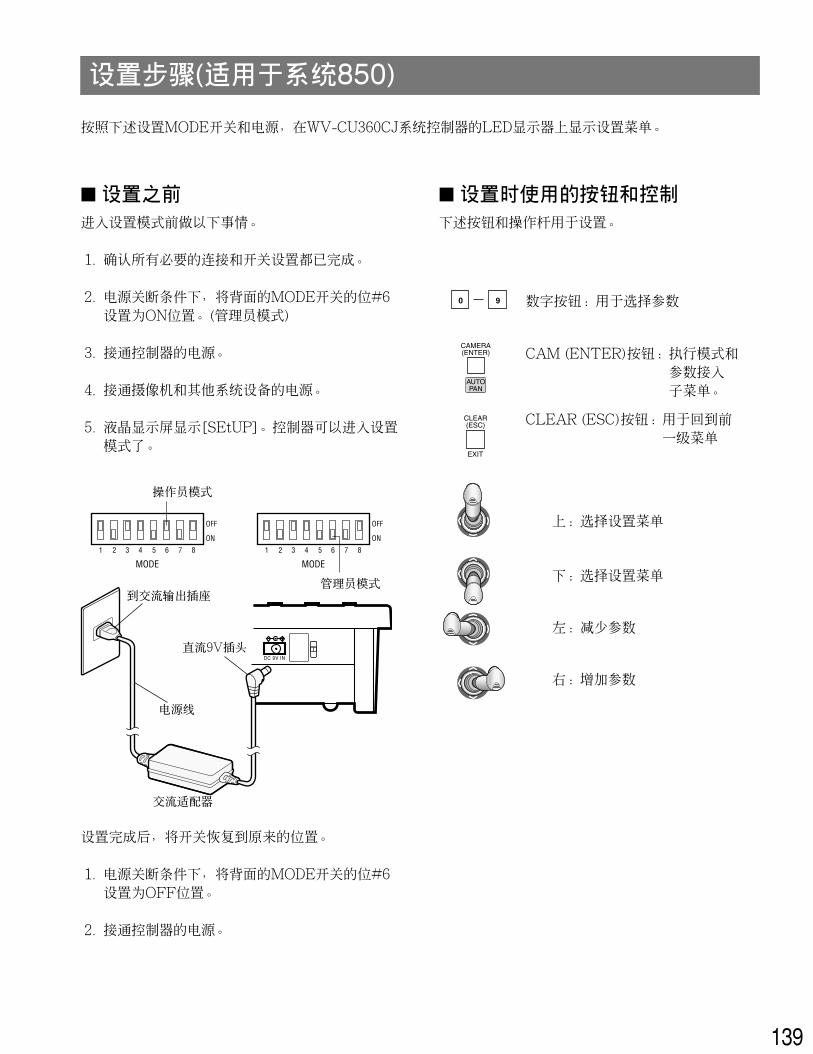
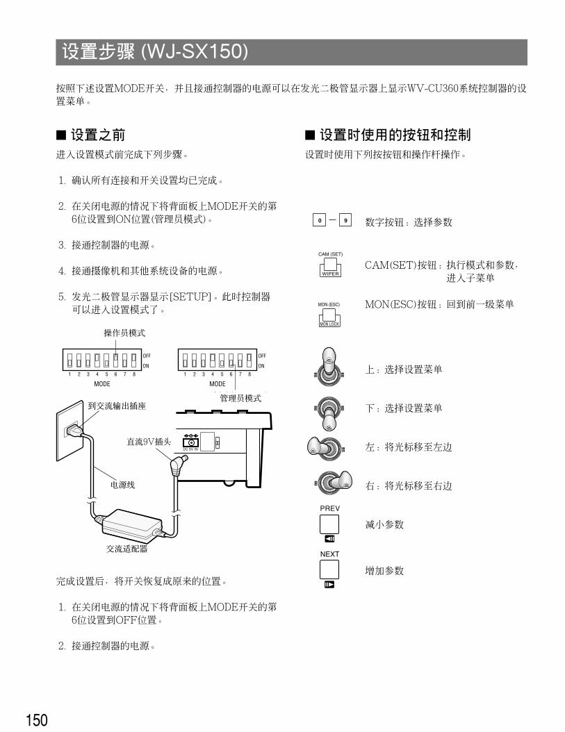
� Prior to SetupDo the following before entering the setup mode.
1. Confirm that all necessary connections and switch set-tings are complete.
2. With the power turned off, move bit #6 of the MODEswitch on the rear to ON position.
3. Supply power to the controller.
4. Turn on the power of cameras and other system units.
5. The LCD displays [SEtUP]. The controller is ready toenter the setup mode.
When setup is completed, restore the switch to its originalposition.
1. With the power turned off, move bit #6 of the MODEswitch on the rear to OFF position.
2. Supply power to the controller.
� Buttons and Controls Used for SetupThe following buttons and joystick operations are used inthe setup operation. There are three ways to select a para-meter, but the following pages only describe the selectionby use of the joystick. Instead of operating the joystick, youcan enter the number enclosed in brackets with the numer-ic keys or press the plus and minus buttons.
0 9
Numeric buttons: To select a parameterTo enter a password orparameter
CAM/SET button: To confirm the selectedmenu, selected parame-ter or entered passwordTo enter a submenu
MON/ESC button: To return to the previousmenu
CAM
SET
MON
ESC
Up: To select a setup menu
Down: To select a setup menu
Left: To decrease the parameter
Right: To increase the parameter
EL-ZOOM
STILL
–
+
or
or
18
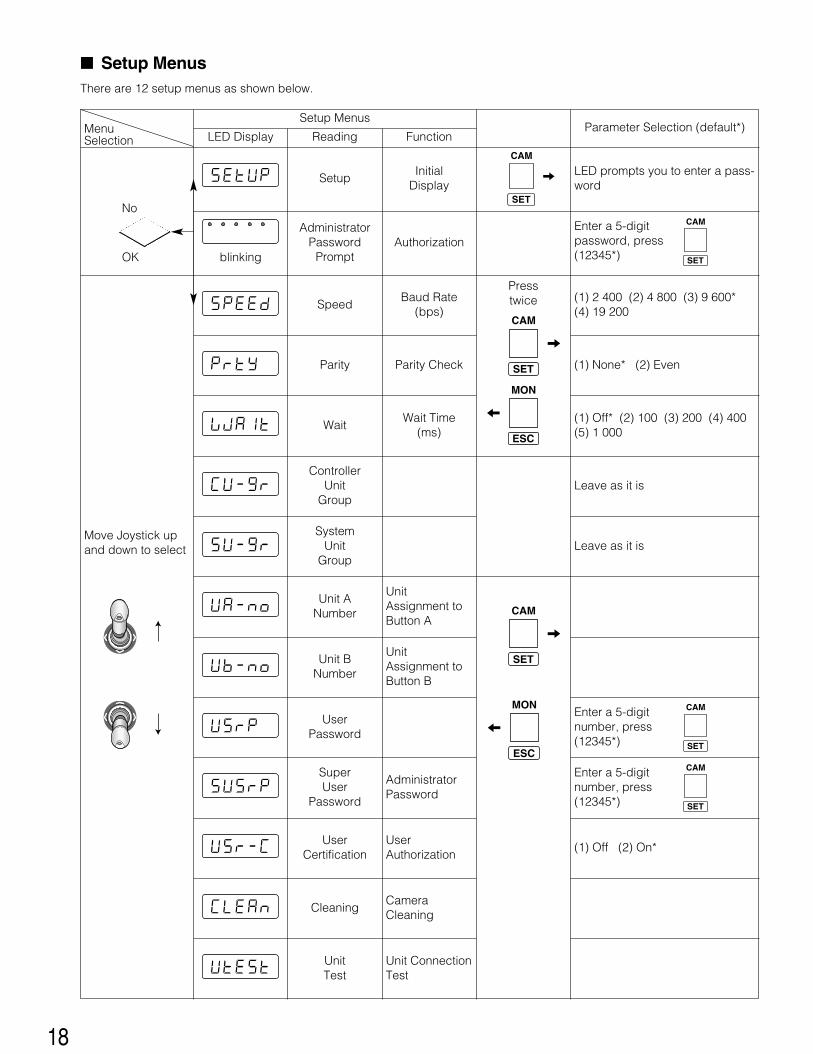
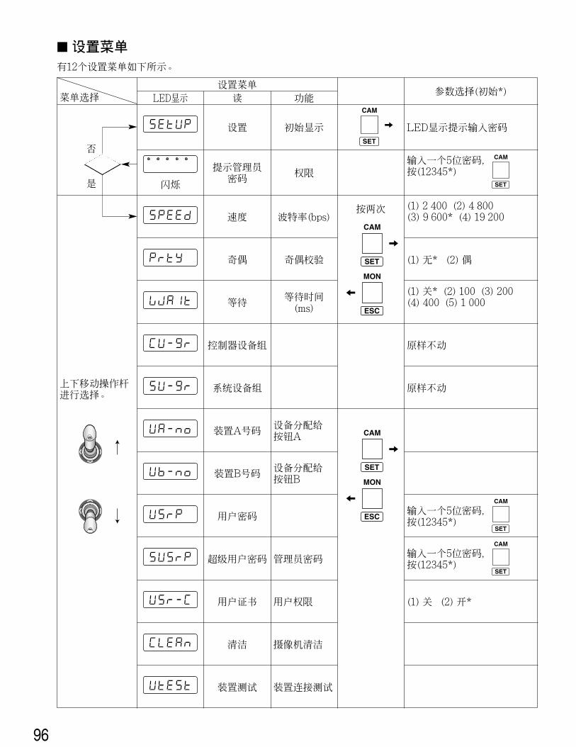
� Setup MenusThere are 12 setup menus as shown below.
Menu Selection
Move Joystick upand down to select
Setup MenusParameter Selection (default*)
LED Display
blinking
Setup
AdministratorPassword
Prompt
Speed
Parity
Wait
ControllerUnit
Group
SystemUnit
Group
Unit ANumber
Unit BNumber
UserPassword
SuperUser
Password
UserCertification
Cleaning
UnitTest
InitialDisplay
Authorization
Baud Rate(bps)
Presstwice
Parity Check
Wait Time(ms)
UnitAssignment toButton A
UnitAssignment toButton B
AdministratorPassword
UserAuthorization
CameraCleaning
Unit ConnectionTest
CAM
SET
CAM
SET
MON
ESC
CAM
SET
LED prompts you to enter a pass-word
Enter a 5-digit password, press(12345*)
(1) 2 400 (2) 4 800 (3) 9 600*(4) 19 200
(1) None* (2) Even
(1) Off* (2) 100 (3) 200 (4) 400(5) 1 000
Leave as it is
Leave as it is
Enter a 5-digit number, press(12345*)
Reading Function
OK
NoCAM
SET
CAM
SET
Enter a 5-digit number, press(12345*)
(1) Off (2) On*
CAM
SET
MON
ESC
19
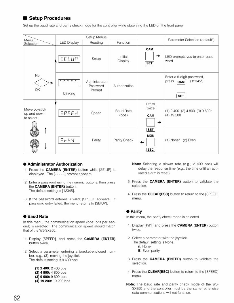
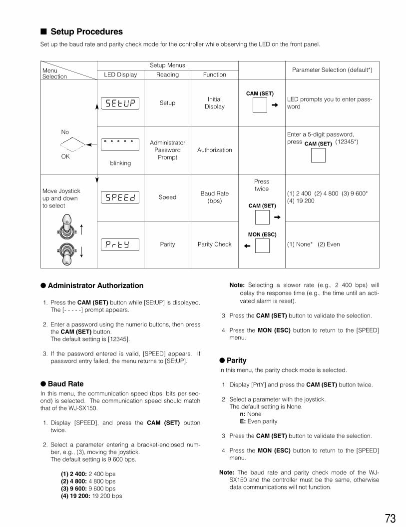
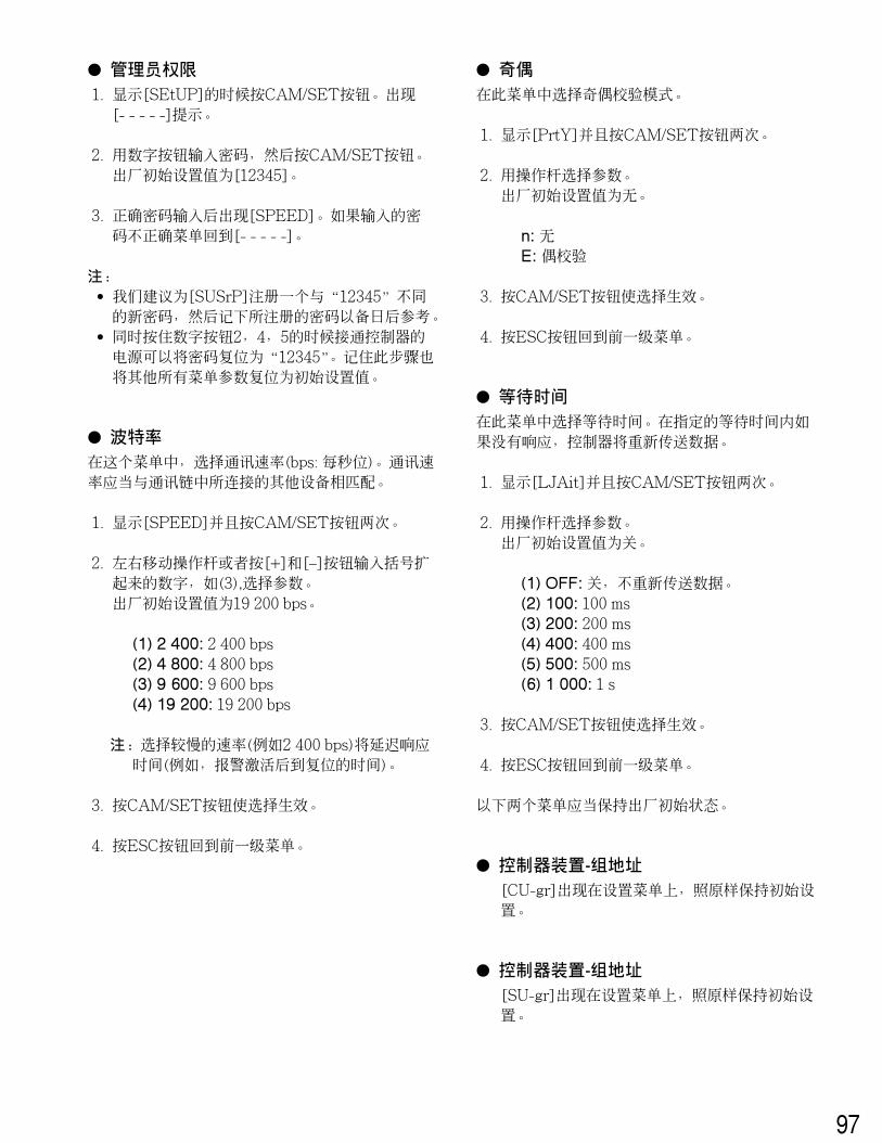
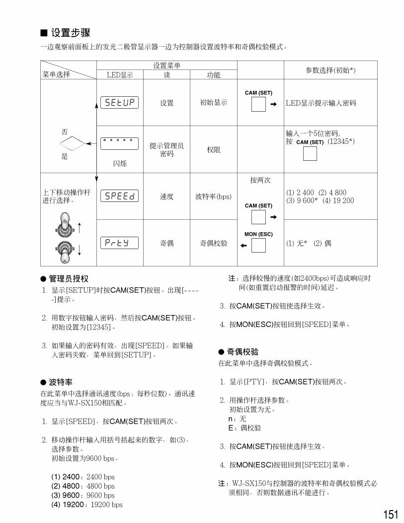
� Administrator Authorization1. Press the CAM/SET button while [SEtUP] is displayed.
The [- - - - -] prompt appears.
2. Enter a password with the numeric buttons, then pressthe CAM/SET button.The default setting is [12345].
3. [SPEED] appears when the right password is entered. Ifpassword entry failed, the menu returns to [- - - - -].
Notes: • We recommend that you register a new password dif-
ferent from “12345” in [SUSrP], and note down the reg-istered password for future reference.
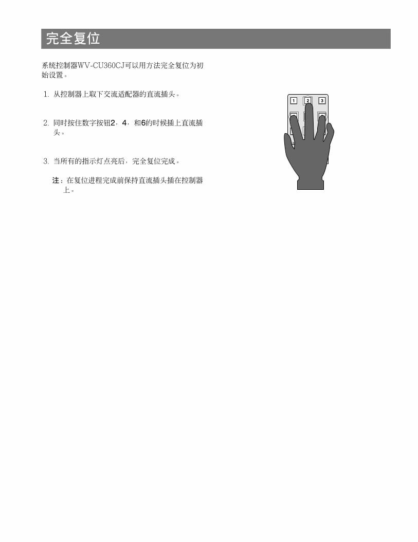
• Powering up the controller while holding down numericbuttons 2, 4 and 5 simultaneously will reset the pass-word to “12345”. Remember that this procedure alsoresets all other menu parameters to the default settings.
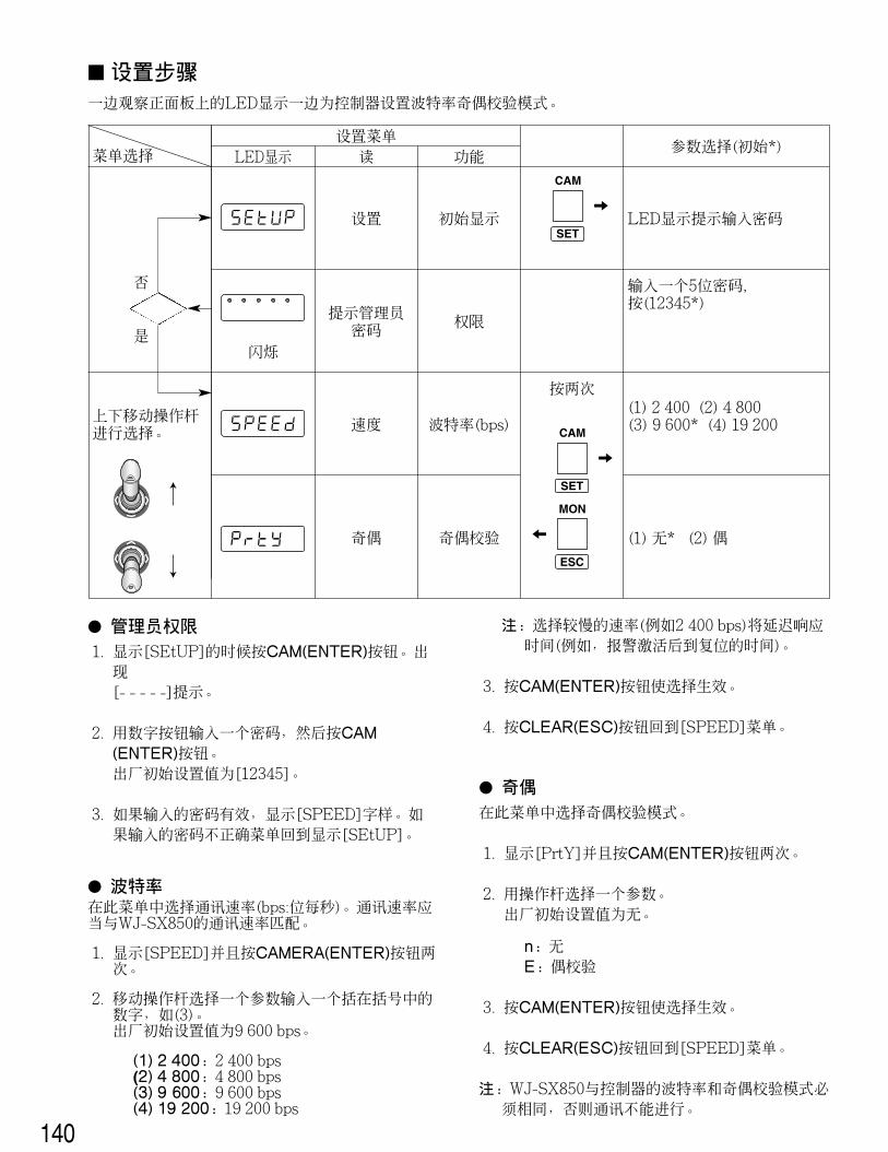
� Baud RateIn this menu, the communication speed (bps: bits per sec-ond) is selected. The communication speed should matchthat of the other units connected in the communicationchain.
1. Display [SPEED] and press the CAM/SET button twice.
2. Select a parameter entering a bracket-enclosed num-ber, e.g., (3), moving the joystick right and left, orpressing the [+] and [–] button.The default setting is 19 200 bps.
Note: Selecting a slower rate (e.g., 2 400 bps) willdelay the response time (e.g., the time until an acti-vated alarm is reset).
3. Press the CAM/SET button to validate the selection.
4. Press the ESC button to go back to the previous menu.
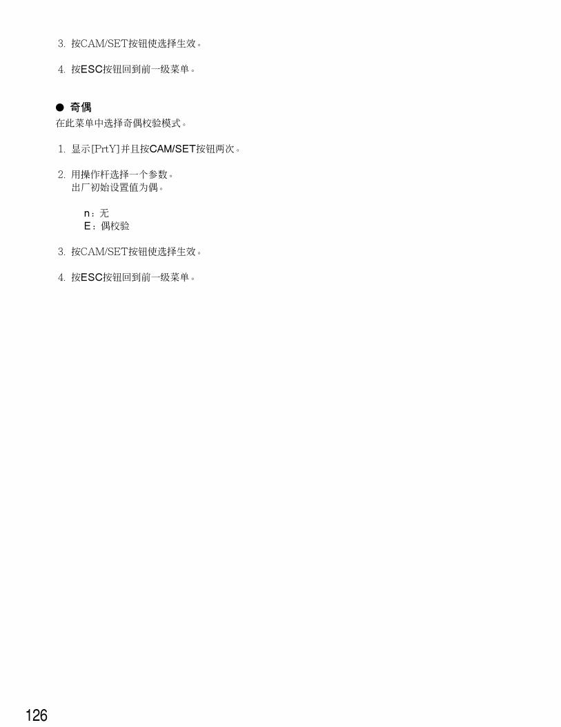
� ParityIn this menu, the parity check mode is selected.
1. Display [PrtY] and press the CAM/SET button twice.
2. Select a parameter with the joystick.The default setting is None.
n: NoneE: Even parity
3. Press the CAM/SET button to validate the selection.
4. Press the ESC button to go back to the previous menu.
� Wait TimeIn this menu a wait time is selected. The controller willretransmit data when there is no response during the speci-fied wait time.
1. Display [LJAit] and press the CAM/SET button twice.
2. Select a parameter with the joystick.The default setting is Off.
(1) OFF: Off, no retransmission of data(2) 100: 100 ms(3) 200: 200 ms(4) 400: 400 ms(5) 500: 500 ms(6) 1 000: 1 s
3. Press the CAM/SET button to validate the selection.
4. Press the ESC button to go back to the previous menu.
The following two menus should be maintained in thedefault condition.
� Controller Unit-Group Address[CU-gr] appears on the Setup menu, but leave thedefault as it is.
� System Unit-Group Address[SU-gr] appears on the Setup menu, but leave thedefault as it is.
20
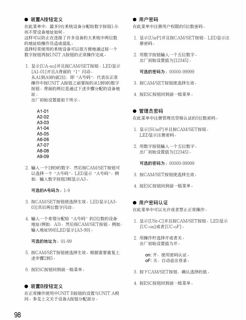
� Unit A button AssignmentIn this menu, a maximum of 9 system units is assigned tonumeric buttons 1-9 regardless of unit address. This is to avoid double-digit unit addresses which canoccur in a large system with many units connected andcould confuse operators.A frequently used system unit can be easily selected in nor-mal operation by pressing one numeric button and then theUNIT A button.
1. Display [UA-no] and press the CAM/SET button. TheLED displays [A1-01] while “1” following A blinks.The first 2 digits from A1 to A9, “A numbers”, stand fornumeric buttons from 1 to 9 to be pressed prior to UNITA button in normal operation. The next 2 digits are theunit address assigned in the following procedures.The default setting is shown below.
A1-01A2-02A3-03A1-04A5-05A6-06A7-07A8-08A9-09
2. Select an “A number” entering a number from 1 to 9,then press the CAM/SET button. The LED displays “Anumber” A3 when numeric button 3 is entered forexample.
Available A numbers: 1-9
3. Press the CAM/SET button to validate the selection. TheLED displays [A3-03] while the next two digits are blink-ing.
4. Enter a 2-digit unit address that you wish to assign tothe “A number” (e.g., A3), then press the CAM/SET but-ton. The LED displays [A3-99], for example, when youenter unit address 99.
Available addresses: 01-99
5. Press the CAM/SET button to validate the selection.Repeat above the steps 2 to 5 as needed.
6. Press the ESC button to go back to the previous menu.
� Unit B button AssignmentThe UNIT B button is set up in the same way as the UNIT Abutton for use in normal operation. Refer to the abovedescription for Unit A button Assignment.
� User PasswordIn this menu, a 5-digit password for user authorization isregistered.
1. Display [UsrP ] and press the CAM/SET button. TheLED displays the registered password.
2. Enter a 5-digit password with the numeric buttons. The default setting is [12345].
Available password digits: 00000-99999
3. Press the CAM/SET button to validate the selection.
4. Press the ESC button to go back to the previous menu.
� Administrator PasswordIn this menu, a 5-digit password for administrator certifica-tion is registered.
1. Display [SUsrP] and press the CAM/SET button. TheLED displays the registered password.
2. Enter a 5-digit password with the numeric buttons. The default setting is [12345].
Available password digits: 00000-99999
3. Press the CAM/SET button to validate the selection.
4. Press the ESC button to go back to the previous menu.
� User Password CertificationIn this menu, password certification in normal operation isenabled or disabled.
1. Display [USr-C] and press the CAM/SET button. TheLED displays [UC-on] or [UC-oF].
2. Select On or Off with the joystick controller. The default setting is On.
on: Password certification enabled.oF: Auto log-in
3. Press the CAM/SET button to confirm the selection.
4. Press the ESC button to go back to the previous menu.
21
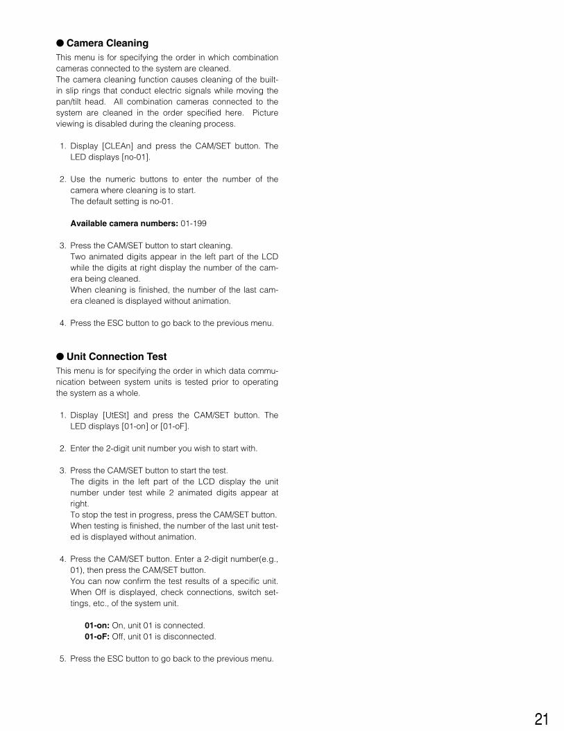
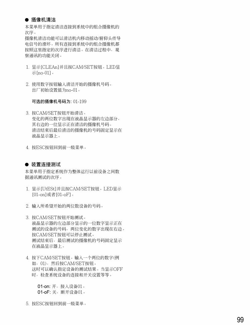
� Camera CleaningThis menu is for specifying the order in which combinationcameras connected to the system are cleaned.The camera cleaning function causes cleaning of the built-in slip rings that conduct electric signals while moving thepan/tilt head. All combination cameras connected to thesystem are cleaned in the order specified here. Pictureviewing is disabled during the cleaning process.
1. Display [CLEAn] and press the CAM/SET button. TheLED displays [no-01].
2. Use the numeric buttons to enter the number of thecamera where cleaning is to start.The default setting is no-01.
Available camera numbers: 01-199
3. Press the CAM/SET button to start cleaning.Two animated digits appear in the left part of the LCDwhile the digits at right display the number of the cam-era being cleaned.When cleaning is finished, the number of the last cam-era cleaned is displayed without animation.
4. Press the ESC button to go back to the previous menu.
� Unit Connection TestThis menu is for specifying the order in which data commu-nication between system units is tested prior to operatingthe system as a whole.
1. Display [UtESt] and press the CAM/SET button. TheLED displays [01-on] or [01-oF].
2. Enter the 2-digit unit number you wish to start with.
3. Press the CAM/SET button to start the test.The digits in the left part of the LCD display the unitnumber under test while 2 animated digits appear atright.To stop the test in progress, press the CAM/SET button.When testing is finished, the number of the last unit test-ed is displayed without animation.
4. Press the CAM/SET button. Enter a 2-digit number(e.g.,01), then press the CAM/SET button.You can now confirm the test results of a specific unit.When Off is displayed, check connections, switch set-tings, etc., of the system unit.
01-on: On, unit 01 is connected.01-oF: Off, unit 01 is disconnected.
5. Press the ESC button to go back to the previous menu.
22
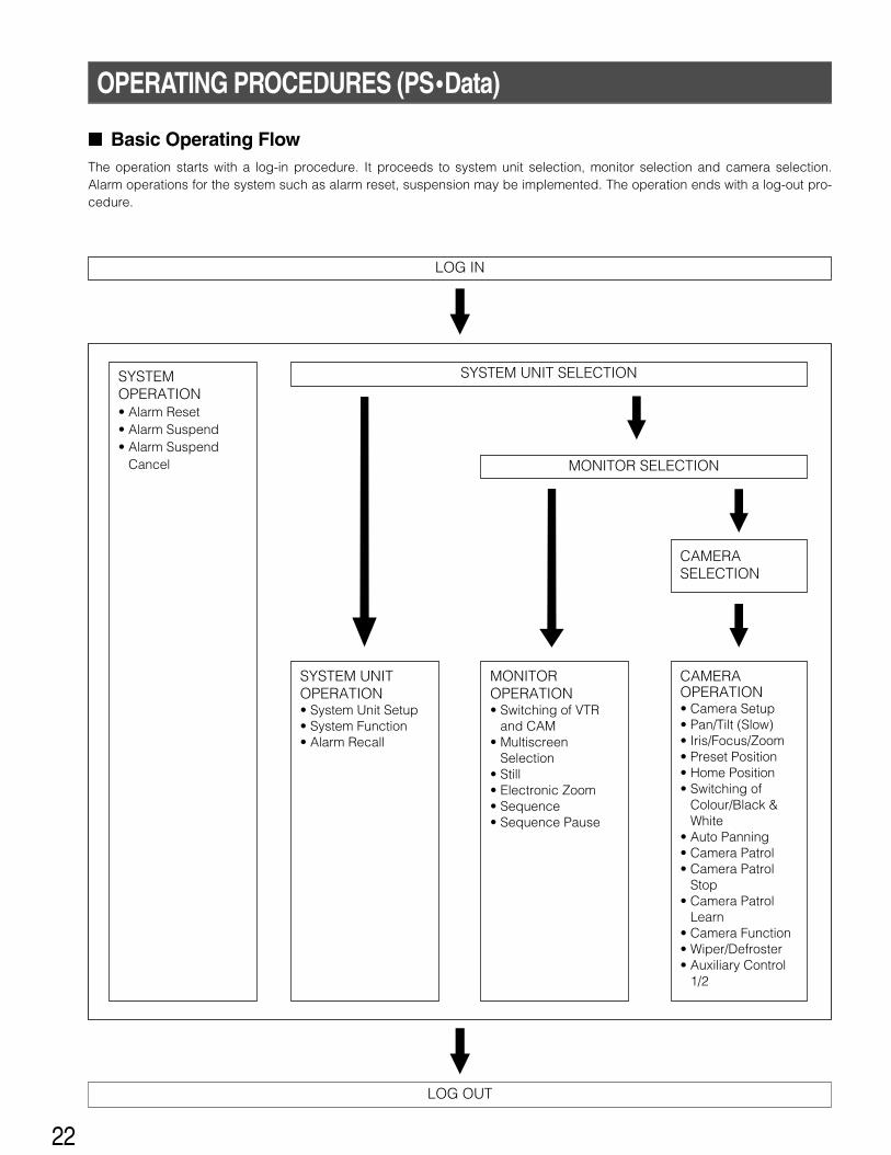
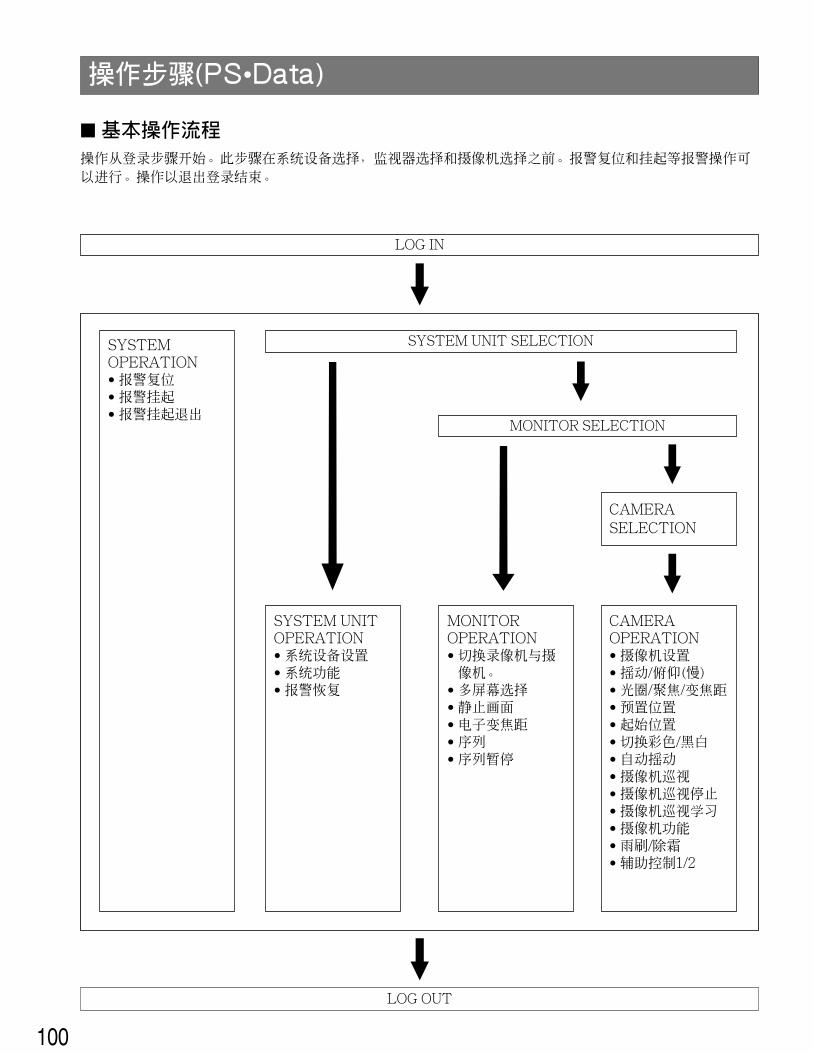
� Basic Operating FlowThe operation starts with a log-in procedure. It proceeds to system unit selection, monitor selection and camera selection.Alarm operations for the system such as alarm reset, suspension may be implemented. The operation ends with a log-out pro-cedure.
OPERATING PROCEDURES (PS•Data)
LOG IN
SYSTEM UNIT SELECTION
MONITOR SELECTION
LOG OUT
SYSTEM OPERATION• Alarm Reset• Alarm Suspend• Alarm Suspend
Cancel
SYSTEM UNITOPERATION• System Unit Setup• System Function• Alarm Recall
CAMERAOPERATION• Camera Setup• Pan/Tilt (Slow)• Iris/Focus/Zoom• Preset Position• Home Position• Switching of
Colour/Black &White
• Auto Panning• Camera Patrol• Camera Patrol
Stop• Camera Patrol
Learn• Camera Function• Wiper/Defroster• Auxiliary Control
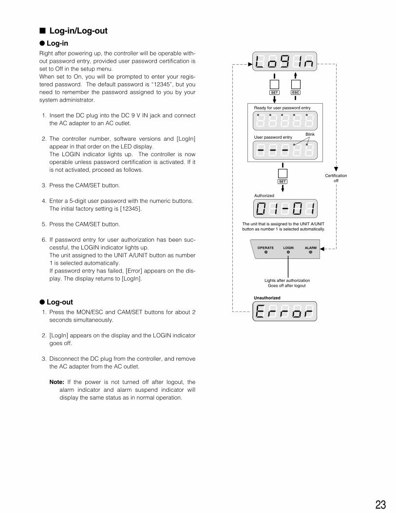
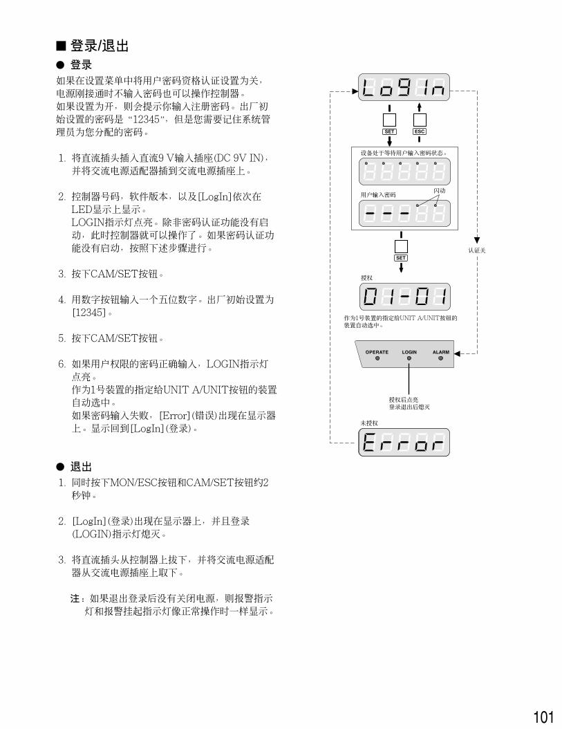
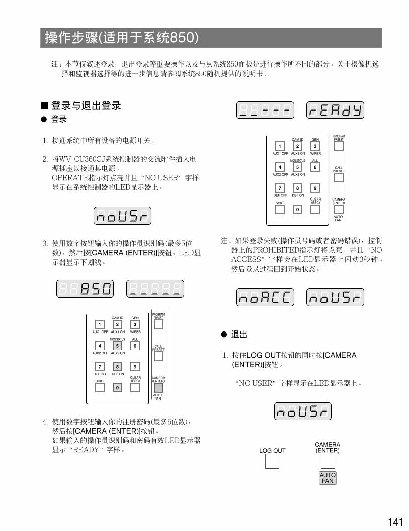
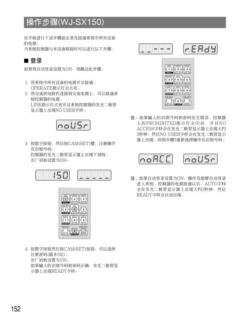
� Log-in/Log-out� Log-inRight after powering up, the controller will be operable with-out password entry, provided user password certification isset to Off in the setup menu.When set to On, you will be prompted to enter your regis-tered password. The default password is “12345”, but youneed to remember the password assigned to you by yoursystem administrator.
1. Insert the DC plug into the DC 9 V IN jack and connectthe AC adapter to an AC outlet.
2. The controller number, software versions and [LogIn]appear in that order on the LED display.The LOGIN indicator lights up. The controller is nowoperable unless password certification is activated. If itis not activated, proceed as follows.
3. Press the CAM/SET button.
4. Enter a 5-digit user password with the numeric buttons.The initial factory setting is [12345].
5. Press the CAM/SET button.
6. If password entry for user authorization has been suc-cessful, the LOGIN indicator lights up.The unit assigned to the UNIT A/UNIT button as number1 is selected automatically.If password entry has failed, [Error] appears on the dis-play. The display returns to [LogIn].
� Log-out1. Press the MON/ESC and CAM/SET buttons for about 2
seconds simultaneously.
2. [LogIn] appears on the display and the LOGIN indicatorgoes off.
3. Disconnect the DC plug from the controller, and removethe AC adapter from the AC outlet.
Note: If the power is not turned off after logout, thealarm indicator and alarm suspend indicator willdisplay the same status as in normal operation.
SET
SET
ESC
Unauthorized
OPERATE LOGIN ALARM
SET
Ready for user password entry
Authorized
User password entryBlink
The unit that is assigned to the UNIT A/UNIT button as number 1 is selected automatically.
Lights after authorization Goes off after logout
Certificationoff
24
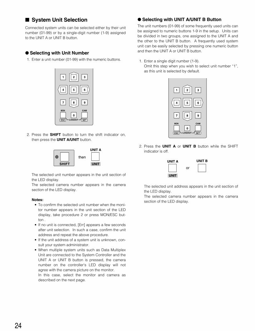
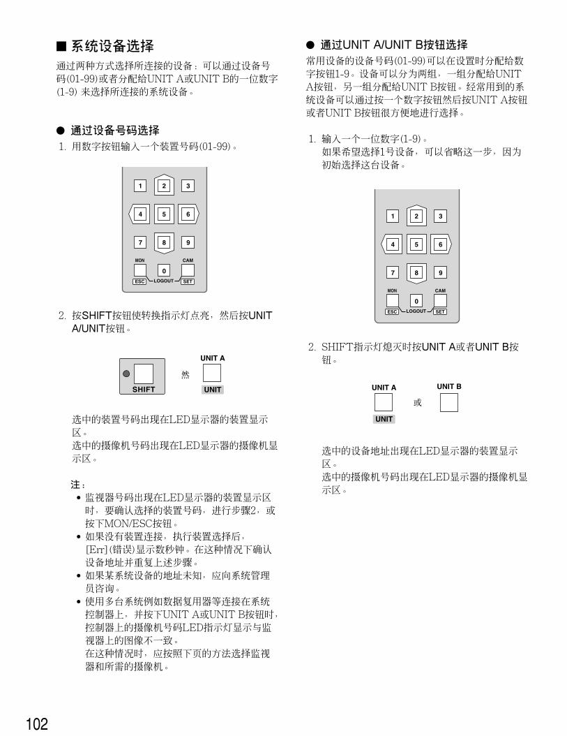
� Selecting with UNIT A/UNIT B ButtonThe unit numbers (01-99) of some frequently used units canbe assigned to numeric buttons 1-9 in the setup. Units canbe divided in two groups, one assigned to the UNIT A andthe other to the UNIT B button. A frequently used systemunit can be easily selected by pressing one numeric buttonand then the UNIT A or UNIT B button.
1. Enter a single digit number (1-9). Omit this step when you wish to select unit number “1”,as this unit is selected by default.
2. Press the UNIT A or UNIT B button while the SHIFTindicator is off.
The selected unit address appears in the unit section ofthe LED display.The selected camera number appears in the camerasection of the LED display.
� System Unit SelectionConnected system units can be selected either by their unitnumber (01-99) or by a single-digit number (1-9) assignedto the UNIT A or UNIT B button.
� Selecting with Unit Number1. Enter a unit number (01-99) with the numeric buttons.
2. Press the SHIFT button to turn the shift indicator on,then press the UNIT A/UNIT button.
The selected unit number appears in the unit section ofthe LED display.The selected camera number appears in the camerasection of the LED display.
Notes:• To confirm the selected unit number when the moni-
tor number appears in the unit section of the LEDdisplay, take procedure 2 or press MON/ESC but-ton .
• If no unit is connected, [Err] appears a few secondsafter unit selection. In such a case, confirm the unitaddress and repeat the above procedure.
• If the unit address of a system unit is unknown, con-sult your system administrator.
• When multiple system units such as Data MultiplexUnit are connected to the System Controller and theUNIT A or UNIT B button is pressed, the cameranumber on the controller's LED display will notagree with the camera picture on the monitor.In this case, select the monitor and camera asdescribed on the next page.
MON CAM
LOGOUTESC SET
SHIFT
UNIT A
then
UNIT
MON CAM
LOGOUTESC SET
UNIT A
or
UNIT
UNIT B
25
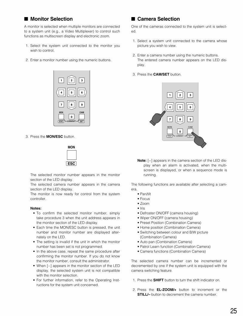
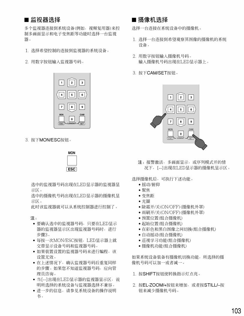
� Monitor SelectionA monitor is selected when multiple monitors are connectedto a system unit (e.g., a Video Multiplexer) to control suchfunctions as multiscreen display and electronic zoom.
1. Select the system unit connected to the monitor youwish to control.
2. Enter a monitor number using the numeric buttons.
3. Press the MON/ESC button.
The selected monitor number appears in the monitorsection of the LED display.The selected camera number appears in the camerasection of the LED display.The monitor is now ready for control from the systemcontroller.
Notes:• To confirm the selected monitor number, simply
take procedure 3 when the unit address appears inthe monitor section of the LED display.
• Each time the MON/ESC button is pressed, the unitnumber and monitor number are displayed alter-nately on the LED.
• The setting is invalid if the unit in which the monitornumber has been set is not programmed.
• In the above case, repeat the same procedure afterconfirming the monitor number. If you do not knowthe monitor number, consult the administrator.
• When [--] appears in the monitor section of the LEDdisplay, the selected system unit is not compatiblewith the monitor selection.
• For further information, refer to the Operating Inst-ructions for the system unit concerned.
MON CAM
LOGOUTESC SET
MON
ESC
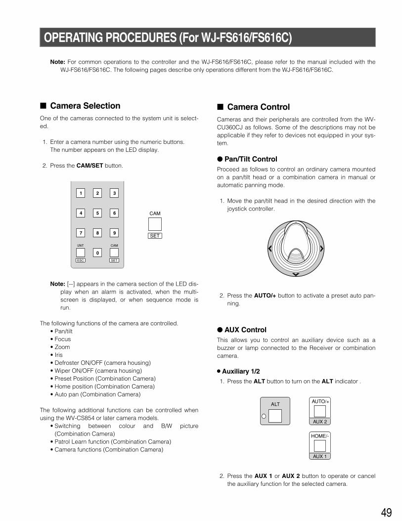
� Camera SelectionOne of the cameras connected to the system unit is select-ed.
1. Select a system unit connected to the camera whosepicture you wish to view.
2. Enter a camera number using the numeric buttons.The entered camera number appears on the LED dis-play.
3. Press the CAM/SET button.
Note: [--] appears in the camera section of the LED dis-play when an alarm is activated, when the multi-screen is displayed, or when a sequence mode isrunning.
The following functions are available after selecting a cam-era.
• Pan/tilt• Focus• Zoom• Iris• Defroster ON/OFF (camera housing)• Wiper ON/OFF (camera housing)• Preset Position (Combination Camera)• Home position (Combination Camera)• Switching between colour and B/W picture
(Combination Camera)• Auto pan (Combination Camera)• Patrol Learn function (Combination Camera)• Camera functions (Combination Camera)
The selected camera number can be incremented ordecremented by one if the system unit is equipped with thecamera switching feature.
1. Press the SHIFT button to turn the shift indicator on.
2. Press the EL-ZOOM/+ button to increment or theSTILL/– button to decrement the camera number.
MON CAM
LOGOUTESC SET
26
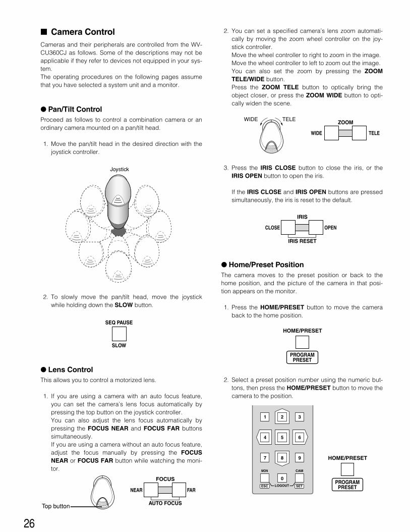
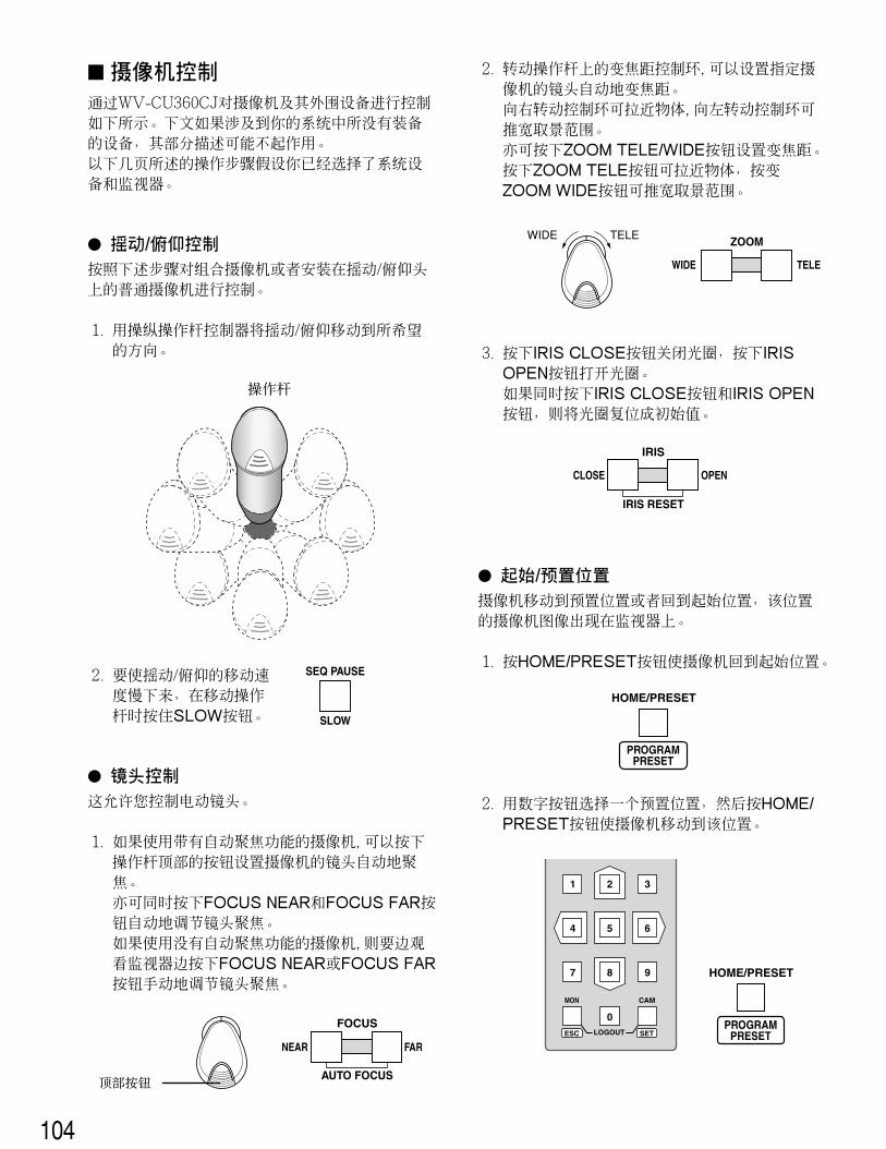
2. You can set a specified camera’s lens zoom automati-cally by moving the zoom wheel controller on the joy-stick controller.Move the wheel controller to right to zoom in the image.Move the wheel controller to left to zoom out the image.You can also set the zoom by pressing the ZOOMTELE/WIDE button.Press the ZOOM TELE button to optically bring theobject closer, or press the ZOOM WIDE button to opti-cally widen the scene.
3. Press the IRIS CLOSE button to close the iris, or theIRIS OPEN button to open the iris.
If the IRIS CLOSE and IRIS OPEN buttons are pressedsimultaneously, the iris is reset to the default.
� Home/Preset Position The camera moves to the preset position or back to thehome position, and the picture of the camera in that posi-tion appears on the monitor.
1. Press the HOME/PRESET button to move the cameraback to the home position.
2. Select a preset position number using the numeric but-tons, then press the HOME/PRESET button to move thecamera to the position.
� Camera ControlCameras and their peripherals are controlled from the WV-CU360CJ as follows. Some of the descriptions may not beapplicable if they refer to devices not equipped in your sys-tem.The operating procedures on the following pages assumethat you have selected a system unit and a monitor.
� Pan/Tilt ControlProceed as follows to control a combination camera or anordinary camera mounted on a pan/tilt head.
1. Move the pan/tilt head in the desired direction with thejoystick controller.
2. To slowly move the pan/tilt head, move the joystickwhile holding down the SLOW button.
� Lens ControlThis allows you to control a motorized lens.
1. If you are using a camera with an auto focus feature,you can set the camera’s lens focus automatically bypressing the top button on the joystick controller.You can also adjust the lens focus automatically bypressing the FOCUS NEAR and FOCUS FAR buttonssimultaneously.If you are using a camera without an auto focus feature,adjust the focus manually by pressing the FOCUSNEAR or FOCUS FAR button while watching the moni-tor.
IRIS
CLOSE OPEN
IRIS RESET
WIDE TELE
ZOOM
SEQ PAUSE
SLOW
Joystick
HOME/PRESET
PROGRAMPRESET
MON CAM
LOGOUTESC SET
HOME/PRESET
PROGRAMPRESET
TELEWIDE
NEAR FAR
FOCUS
AUTO FOCUSTop button
27
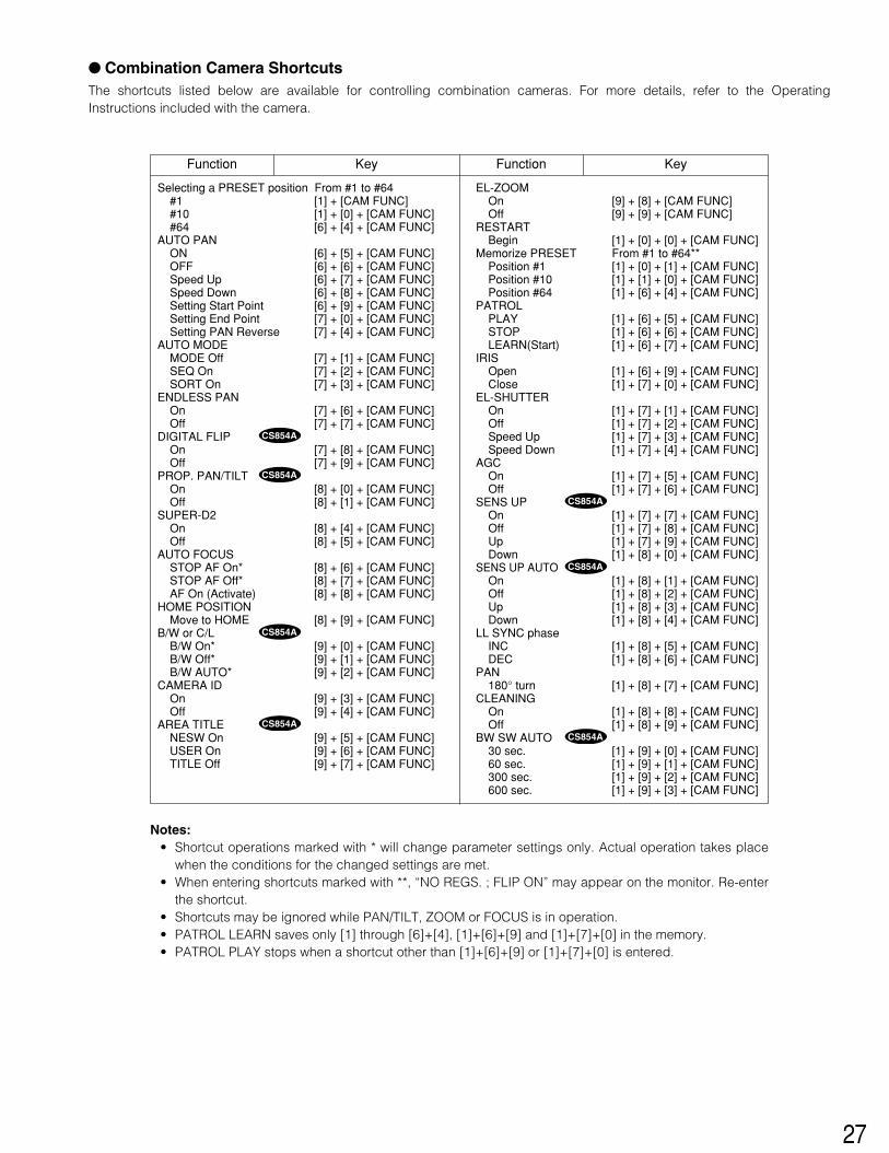
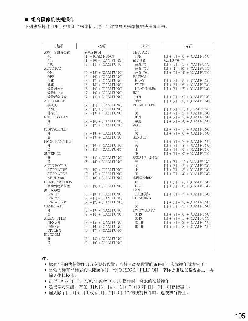
� Combination Camera ShortcutsThe shortcuts listed below are available for controlling combination cameras. For more details, refer to the OperatingInstructions included with the camera.
Selecting a PRESET position From #1 to #64#1 [1] + [CAM FUNC]#10 [1] + [0] + [CAM FUNC]#64 [6] + [4] + [CAM FUNC]
AUTO PANON [6] + [5] + [CAM FUNC]OFF [6] + [6] + [CAM FUNC]Speed Up [6] + [7] + [CAM FUNC]Speed Down [6] + [8] + [CAM FUNC]Setting Start Point [6] + [9] + [CAM FUNC]Setting End Point [7] + [0] + [CAM FUNC]Setting PAN Reverse [7] + [4] + [CAM FUNC]
AUTO MODEMODE Off [7] + [1] + [CAM FUNC]SEQ On [7] + [2] + [CAM FUNC]SORT On [7] + [3] + [CAM FUNC]
BW SW AUTO30 sec. [1] + [9] + [0] + [CAM FUNC]60 sec. [1] + [9] + [1] + [CAM FUNC]300 sec. [1] + [9] + [2] + [CAM FUNC]600 sec. [1] + [9] + [3] + [CAM FUNC]
Function Key Function Key
Notes: • Shortcut operations marked with * will change parameter settings only. Actual operation takes place
when the conditions for the changed settings are met.• When entering shortcuts marked with **, “NO REGS. ; FLIP ON” may appear on the monitor. Re-enter
the shortcut.• Shortcuts may be ignored while PAN/TILT, ZOOM or FOCUS is in operation.• PATROL LEARN saves only [1] through [6]+[4], [1]+[6]+[9] and [1]+[7]+[0] in the memory.• PATROL PLAY stops when a shortcut other than [1]+[6]+[9] or [1]+[7]+[0] is entered.
28
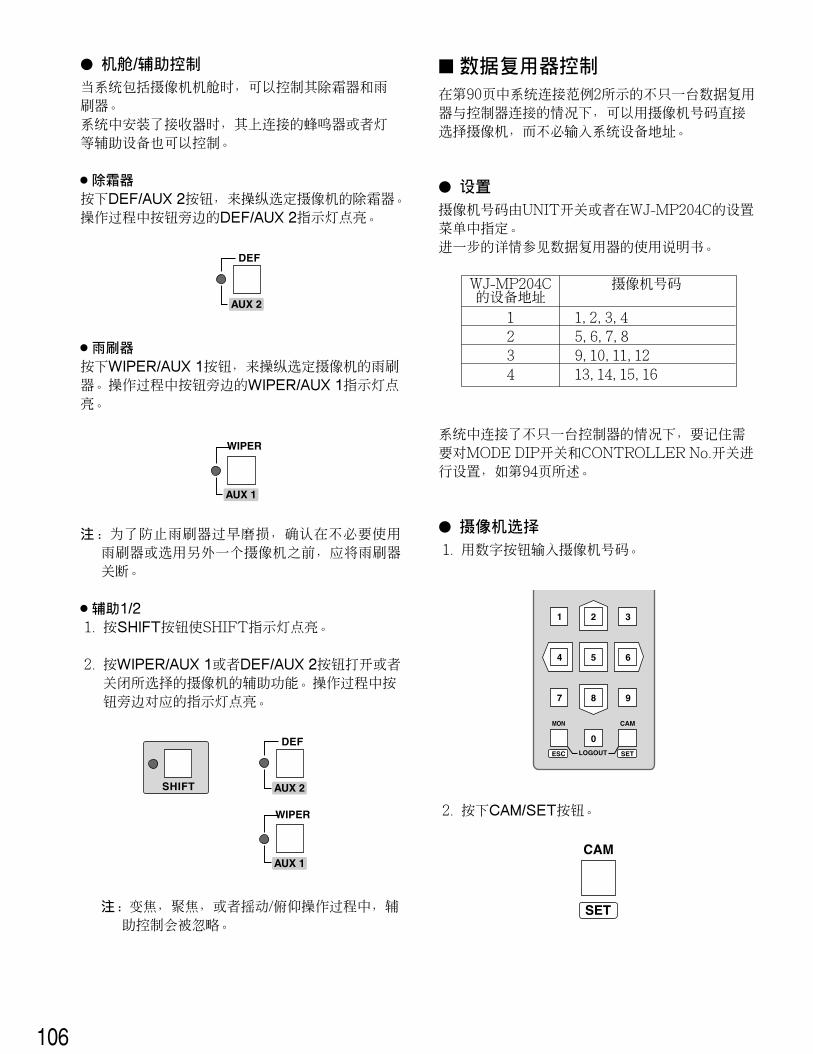
� Housing/AUX ControlWhen your system includes a camera housing, thedefroster and wiper equipped in it are controlled. When aReceiver is installed in the system, an auxiliary device con-nected to it such as a buzzer or lamp will be also con-trolled.
8 DefrosterPress the DEF/AUX 2 button to enable or disable defrosteroperation for the selected camera. The DEF/AUX 2 indica-tor next to the button is lit while it is in operation.
8 WiperPress the WIPER/AUX 1 button to enable or disable wiperoperation for the selected camera. The WIPER/AUX 1 indi-cator next to the button is lit while it is in operation.
Note: To prevent early wiper wear, be sure to turn off thewiper whenever it is not needed, or before selectinganother camera for viewing.
8 Auxiliary 1/21. Press the SHIFT button to turn the SHIFT indicator on.
2. Press the WIPER/AUX 1 or DEF/AUX 2 button toenable or disable the auxiliary function for the selectedcamera. The respective indicator next to the button is litwhile it is in operation.
Note: Auxiliary control may be ignored while zooming,focusing or panning/tilting is in operation.
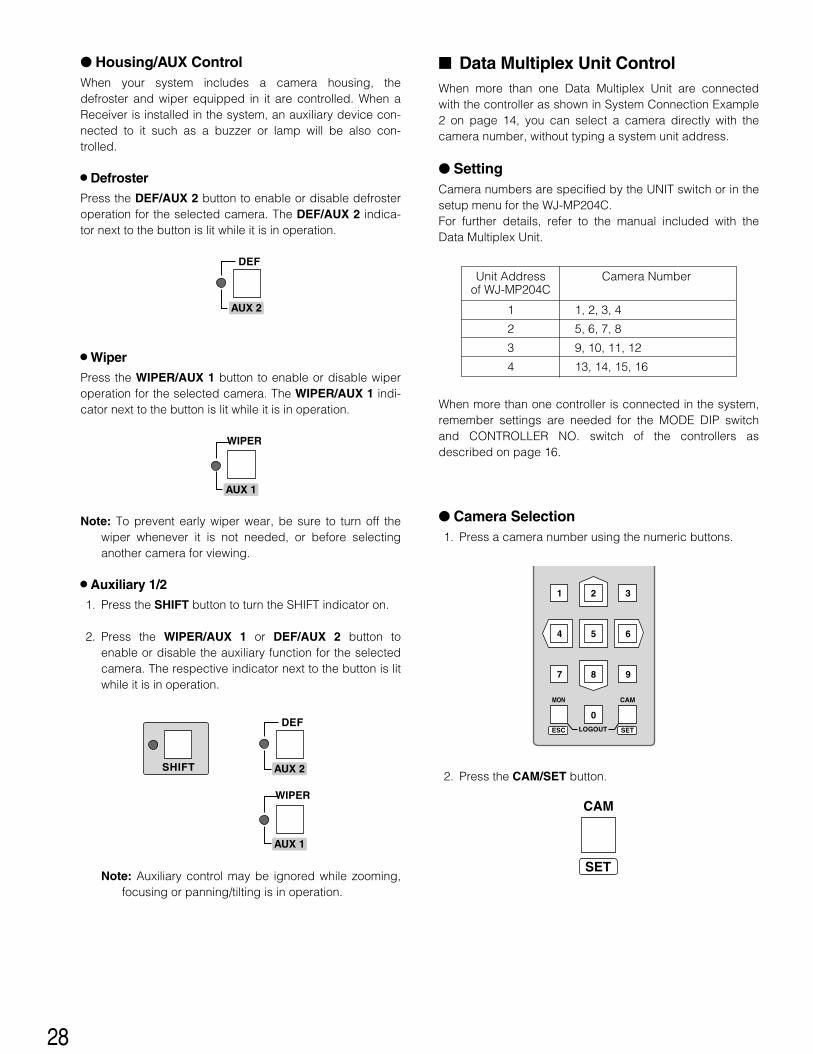
� Data Multiplex Unit ControlWhen more than one Data Multiplex Unit are connectedwith the controller as shown in System Connection Example2 on page 14, you can select a camera directly with thecamera number, without typing a system unit address.
� SettingCamera numbers are specified by the UNIT switch or in thesetup menu for the WJ-MP204C. For further details, refer to the manual included with theData Multiplex Unit.
When more than one controller is connected in the system,remember settings are needed for the MODE DIP switchand CONTROLLER NO. switch of the controllers asdescribed on page 16.
� Camera Selection1. Press a camera number using the numeric buttons.
2. Press the CAM/SET button.
WIPER
AUX 1
DEF
AUX 2
DEF
WIPER
AUX 1
AUX 2SHIFT
Unit Address Camera Number of WJ-MP204C
1 1, 2, 3, 4
2 5, 6, 7, 8
3 9, 10, 11, 12
4 13, 14, 15, 16
MON CAM
LOGOUTESC SET
CAM
SET
29
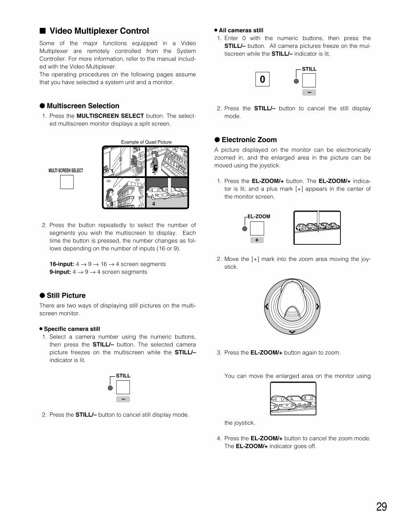
� Video Multiplexer ControlSome of the major functions equipped in a VideoMultiplexer are remotely controlled from the SystemController. For more information, refer to the manual includ-ed with the Video Multiplexer. The operating procedures on the following pages assumethat you have selected a system unit and a monitor.
� Multiscreen Selection1. Press the MULTISCREEN SELECT button. The select-
ed multiscreen monitor displays a split screen.
2. Press the button repeatedly to select the number ofsegments you wish the multiscreen to display. Eachtime the button is pressed, the number changes as fol-lows depending on the number of inputs (16 or 9).
� Still PictureThere are two ways of displaying still pictures on the multi-screen monitor.
8 Specific camera still1. Select a camera number using the numeric buttons,
then press the STILL/– button. The selected camerapicture freezes on the multiscreen while the STILL/–indicator is lit.
2. Press the STILL/– button to cancel still display mode.
8 All cameras still1. Enter 0 with the numeric buttons, then press the
STILL/– button. All camera pictures freeze on the mul-tiscreen while the STILL/– indicator is lit.
2. Press the STILL/– button to cancel the still displaymode.
� Electronic ZoomA picture displayed on the monitor can be electronicallyzoomed in, and the enlarged area in the picture can bemoved using the joystick.
1. Press the EL-ZOOM/+ button. The EL-ZOOM/+ indica-tor is lit, and a plus mark [+] appears in the center ofthe monitor screen.
2. Move the [+] mark into the zoom area moving the joy-stick.
3. Press the EL-ZOOM/+ button again to zoom.
You can move the enlarged area on the monitor using
the joystick.
4. Press the EL-ZOOM/+ button to cancel the zoom mode.The EL-ZOOM/+ indicator goes off.
MULTI SCREEN SELECT 1 2
3 4
Example of Quad Picture
STILL
–
STILL
–
0
EL-ZOOM
+
30
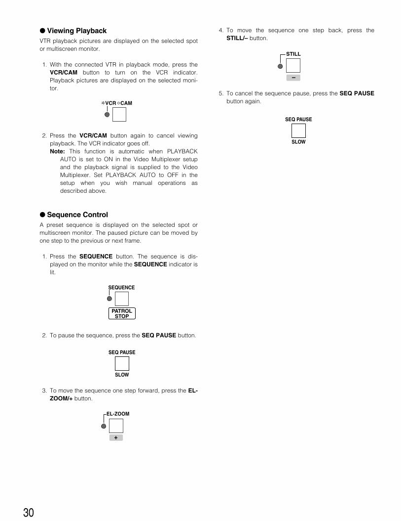
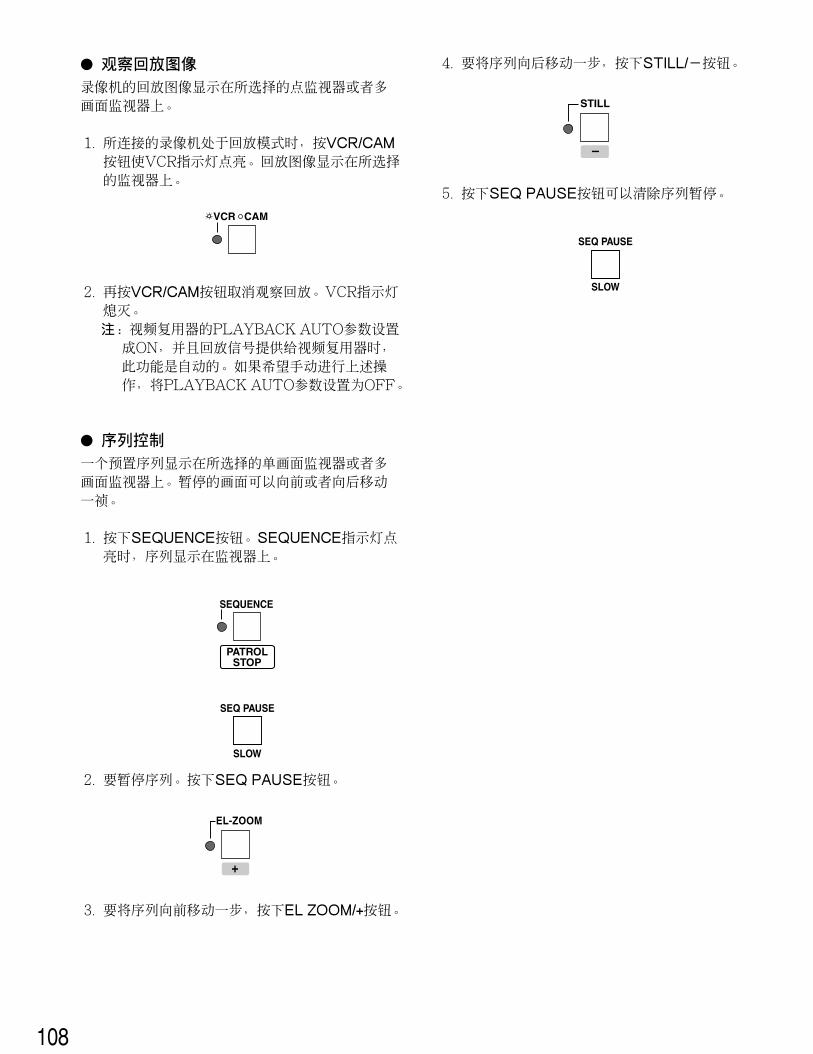
� Viewing PlaybackVTR playback pictures are displayed on the selected spotor multiscreen monitor.
1. With the connected VTR in playback mode, press theVCR/CAM button to turn on the VCR indicator.Playback pictures are displayed on the selected moni-tor.
2. Press the VCR/CAM button again to cancel viewingplayback. The VCR indicator goes off.Note: This function is automatic when PLAYBACK
AUTO is set to ON in the Video Multiplexer setupand the playback signal is supplied to the VideoMultiplexer. Set PLAYBACK AUTO to OFF in thesetup when you wish manual operations asdescribed above.
� Sequence ControlA preset sequence is displayed on the selected spot ormultiscreen monitor. The paused picture can be moved byone step to the previous or next frame.
1. Press the SEQUENCE button. The sequence is dis-played on the monitor while the SEQUENCE indicator islit.
2. To pause the sequence, press the SEQ PAUSE button.
3. To move the sequence one step forward, press the EL-ZOOM/+ button.
4. To move the sequence one step back, press theSTILL/– button.
5. To cancel the sequence pause, press the SEQ PAUSEbutton again.VCR CAM
SEQUENCE
PATROLSTOP
SEQ PAUSE
SLOW
SEQ PAUSE
SLOW
EL-ZOOM
+
STILL
–
31
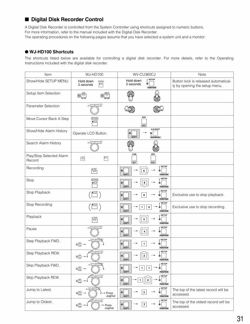
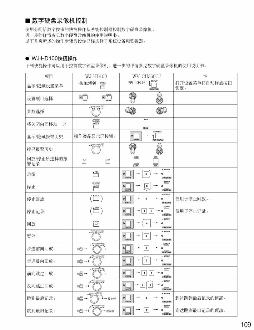
� Digital Disk Recorder ControlA Digital Disk Recorder is controlled from the System Controller using shortcuts assigned to numeric buttons. For more information, refer to the manual included with the Digital Disk Recorder. The operating procedures on the following pages assume that you have selected a system unit and a monitor.
� WJ-HD100 ShortcutsThe shortcuts listed below are available for controlling a digital disk recorder. For more details, refer to the OperatingInstructions included with the digital disk recorder.
Item
SHIFT
SETUP
FUNCTION
Step Playback REW.
Play/Stop Selected AlarmRecord
Show/Hide SETUP MENU
The top of the oldest record will beaccessed.
Jump to Oldest.
WV-CU360CJ
Setup Item Selection
Parameter Selection
Move Cursor Back A Step
Show/Hide Alarm History
Search Alarm History
WJ-HD100 Note
Button lock is released automatical-ly by opening the setup menu.
Operate LCD Button.
STOPSETUP/ESCHold down
2 seconds
STEP
/
PUSH– PAUSE SET/ /
PUSH– PAUSE SET/ /
STOPSETUP/ESC
STOPPLAY
CAM MON
ESCSET
REW/FF
/
SETUP
FUNCTION
Hold down2 seconds
MON
ESC
ALM RESET
ALM RECALLSHIFT
Recording RECSETUP
FUNCTIONSHIFT
Stop
Stop Playback
Stop Recording
STOPSETUP/ESC
STOP
STOP
SETUP
FUNCTIONSHIFT
Playback PLAYSETUP
FUNCTIONSHIFT
PausePUSH– PAUSE SET
/ /SETUP
FUNCTIONSHIFT
Step Playback FWD.PUSH– PAUSE SET
/ /
STEP
/
PUSH– PAUSE SET/ /
STEP
/
SETUP
FUNCTIONSHIFT
SETUP
FUNCTIONSHIFT
Skip Playback FWD.PUSH– PAUSE SET
/ /
REW/FF
/SHIFT
SETUP
FUNCTION
Skip Playback REW.PUSH– PAUSE SET
/ /
REW/FF
/
Jump to Latest. The top of the latest record will beaccessed.
PUSH– PAUSE SET/ /
REW/FF
/Press JogDial
SETUP
FUNCTIONSHIFT
PUSH– PAUSE SET/ /
REW/FF
/Press JogDial
SETUP
FUNCTIONSHIFT
SETUP
FUNCTIONSHIFT
SHIFT
SETUP
FUNCTION
Exclusive use to stop playback.
Exclusive use to stop recording.
Hold down2 seconds
Hold down2 seconds
PressJogDial
PressJogDial
32
SETUP
FUNCTIONSHIFT
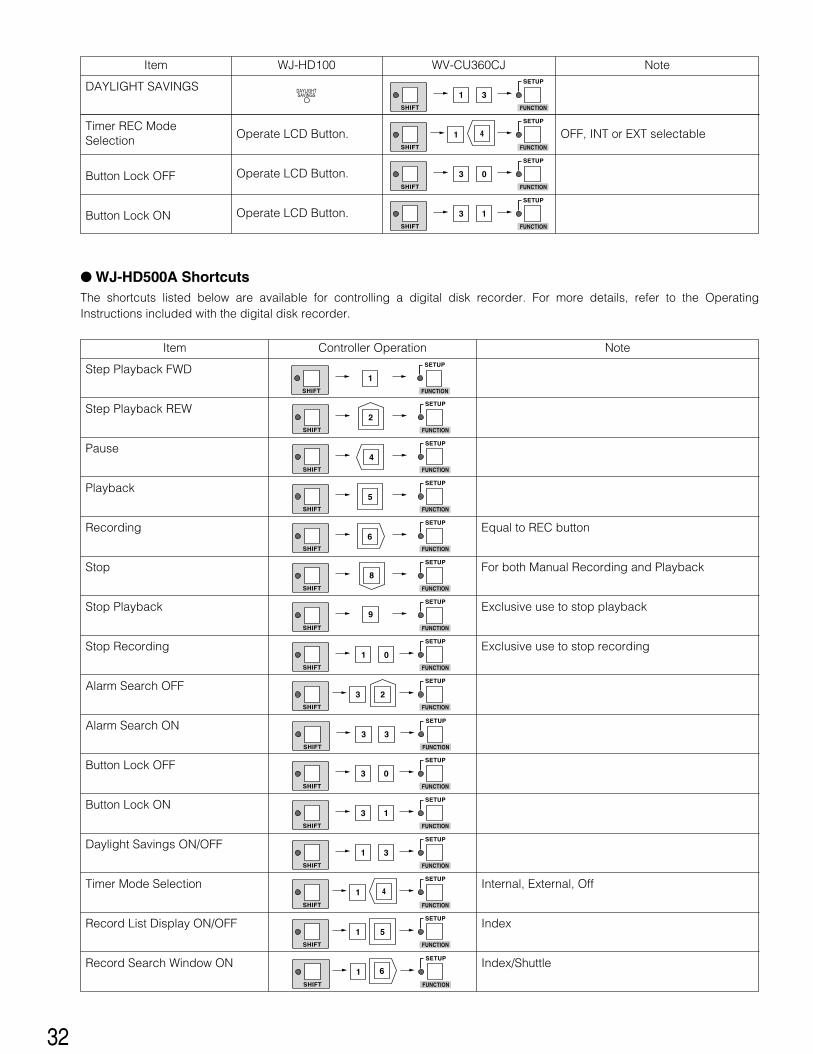
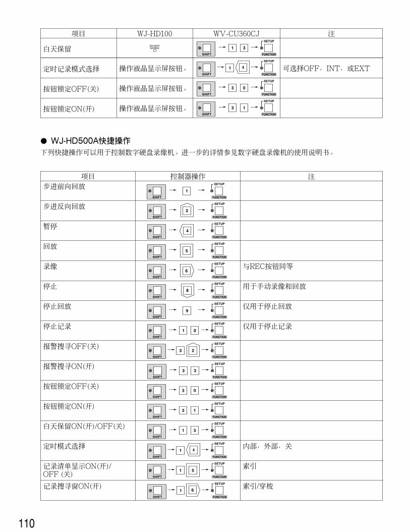
� WJ-HD500A ShortcutsThe shortcuts listed below are available for controlling a digital disk recorder. For more details, refer to the OperatingInstructions included with the digital disk recorder.
DAYLIGHT SAVINGS
OFF, INT or EXT selectable
Operate LCD Button.
Item WV-CU360CJWJ-HD100 Note
DAYLIGHTSAVINGS
SHIFT
SETUP
FUNCTION
31
Timer REC ModeSelection
SHIFT
SETUP
FUNCTION
Button Lock OFF Operate LCD Button.
Operate LCD Button.
Button Lock ONSHIFT
SETUP
FUNCTION
3 1
SHIFT
SETUP
FUNCTION
3 0
Item Controller Operation Note
Step Playback FWD
Step Playback REW
Pause
Playback
Recording
Stop
Stop Playback
Stop Recording
Alarm Search OFF
Alarm Search ON
Button Lock OFF
Button Lock ON
Daylight Savings ON/OFF
Timer Mode Selection
Record List Display ON/OFF
Record Search Window ON
Equal to REC button
For both Manual Recording and Playback
Exclusive use to stop playback
Exclusive use to stop recording
Internal, External, Off
Index
Index/Shuttle
SETUP
FUNCTIONSHIFT
SETUP
FUNCTIONSHIFT
SETUP
FUNCTIONSHIFT
SETUP
FUNCTIONSHIFT
SHIFT
SETUP
FUNCTION
SHIFT
SETUP
FUNCTION
3 3
SETUP
FUNCTIONSHIFT
SETUP
FUNCTIONSHIFT
SHIFT
SETUP
FUNCTION
SHIFT
SETUP
FUNCTION
3 1
SHIFT
SETUP
FUNCTION
3 0
SHIFT
SETUP
FUNCTION
31
SHIFT
SETUP
FUNCTION
SHIFT
SETUP
FUNCTION
SHIFT
SETUP
FUNCTION
33
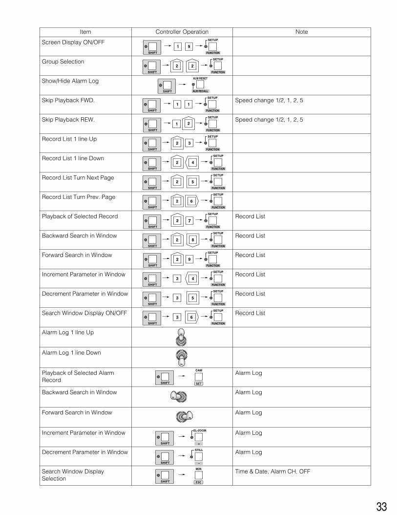
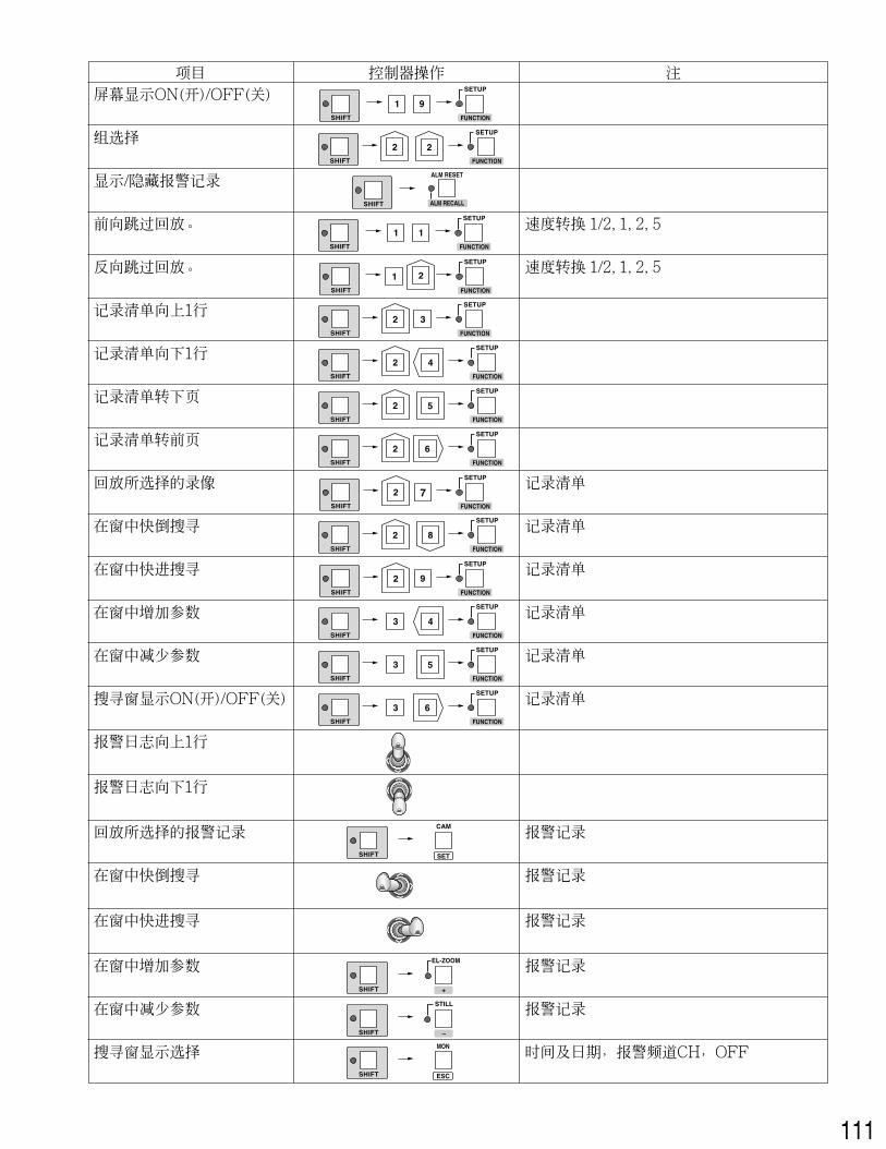
Item Controller Operation Note
Screen Display ON/OFF
Group Selection
Show/Hide Alarm Log
Skip Playback FWD.
Skip Playback REW.
Record List 1 line Up
Record List 1 line Down
Record List Turn Next Page
Record List Turn Prev. Page
Playback of Selected Record
Backward Search in Window
Forward Search in Window
Increment Parameter in Window
Decrement Parameter in Window
Search Window Display ON/OFF
Alarm Log 1 line Up
Alarm Log 1 line Down
Playback of Selected AlarmRecord
Backward Search in Window
Forward Search in Window
Increment Parameter in Window
Decrement Parameter in Window
Search Window DisplaySelection
Speed change 1/2, 1, 2, 5
Speed change 1/2, 1, 2, 5
Record List
Record List
Record List
Record List
Record List
Record List
Alarm Log
Alarm Log
Alarm Log
Alarm Log
Alarm Log
Time & Date, Alarm CH, OFF
SHIFT
SETUP
FUNCTION
SHIFT
SETUP
FUNCTION
SHIFT
ALM RESET
ALM RECALL
SHIFT
SETUP
FUNCTION
SHIFT
SETUP
FUNCTION
SHIFT
SETUP
FUNCTION
SHIFT
SETUP
FUNCTION
SHIFT
SETUP
FUNCTION
SHIFT
SETUP
FUNCTION
SHIFT
SETUP
FUNCTION
SHIFT
SETUP
FUNCTION
SHIFT
SETUP
FUNCTION
SHIFT
SETUP
FUNCTION
SHIFT
SETUP
FUNCTION
SHIFT
SETUP
FUNCTION
SHIFT
CAM
SET
SHIFT
EL-ZOOM
+
SHIFT
STILL
–
SHIFT
MON
ESC
34
Item
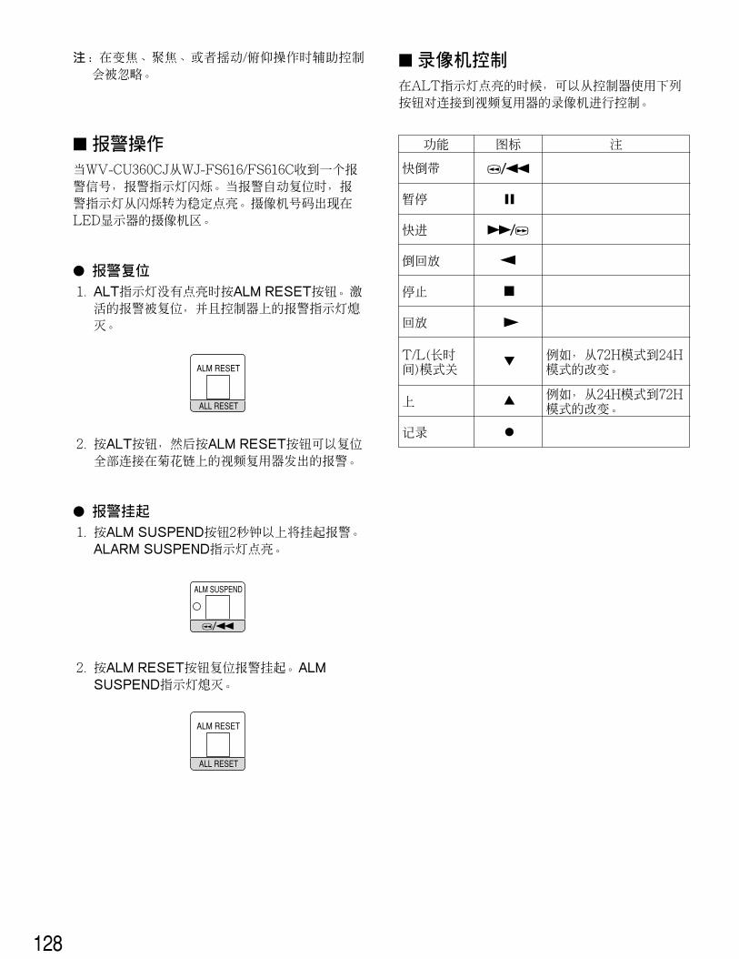
� Alarm OperationWhen the WV-CU360CJ receives an alarm signal from asystem unit, the alarm indicator on the controller blinks.The alarm indicator changes from blinking to steady lightwhen the alarm is automatically reset.The camera number [---] appears in the camera section ofthe LED display.
� Alarm Reset1. Press the ALM RESET/ALM RECALL button.
The alarm indicator on the controller goes off.Notes:
• Alarm reset operations including auto reset areapplied to all system units, not to a selected one.
• Alarm reset mode differs depending on the systemunit connected to the WV-CU360CJ.
• Confirm that the SHIFT button is released.
� Alarm SuspensionThe alarm suspension mode is activated or deactivated.Use this function when you do not want to be disturbed byalarm input as for example during setup operations.
1. Press the ALM SUSPEND button. The ALM SUSPENDindicator lights up.Alarm input is ignored while the indicator is lit.
ALM RESET
ALM RECALL
ALM SUSPEND
2. To cancel alarm suspension, press the ALM SUSPENDbutton again.
Note: The alarm suspension is applied to all systemunits, not to a selected one.
� Alarm RecallThe alarm event log is recalled and displayed on the moni-tor.
1. Select the desired system unit and monitor.
2. Press the ALM RESET/ALM RECALL button while theSHIFT indicator is lit. The ALM RECALL indicator lightsup. The alarm log appears on the monitor.
3. To cancel the alarm recall function, press the ALMRESET/ALM RECALL button while the SHIFT indicatoris lit.
ALM SUSPEND
ALM RESET
ALM RECALLSHIFT
Controller Operation Note
Copy to DVD
Copy Cancel
DVD Copy Record Display Equal to EL-ZOOM
SHIFT
SETUP
FUNCTION
SHIFT
SETUP
FUNCTION
SHIFT
SETUP
FUNCTION
35
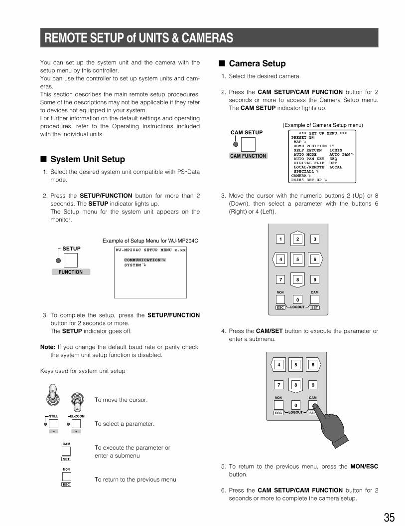
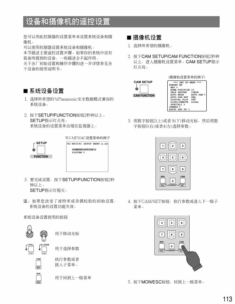
REMOTE SETUP of UNITS & CAMERAS
You can set up the system unit and the camera with thesetup menu by this controller.You can use the controller to set up system units and cam-eras.This section describes the main remote setup procedures.Some of the descriptions may not be applicable if they referto devices not equipped in your system.For further information on the default settings and operatingprocedures, refer to the Operating Instructions includedwith the individual units.
� System Unit Setup1. Select the desired system unit compatible with PS •Data
mode.
2. Press the SETUP/FUNCTION button for more than 2seconds. The SETUP indicator lights up.The Setup menu for the system unit appears on themonitor.
3. To complete the setup, press the SETUP/FUNCTIONbutton for 2 seconds or more.The SETUP indicator goes off.
Note: If you change the default baud rate or parity check,the system unit setup function is disabled.
Keys used for system unit setup
Example of Setup Menu for WJ-MP204C
WJ-MP204C SETUP MENU x.xx
COMMUNICATION SYSTEM
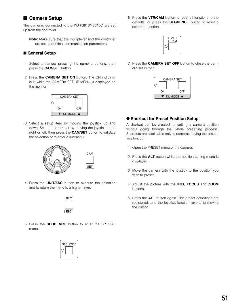
� Camera Setup1. Select the desired camera.
2. Press the CAM SETUP/CAM FUNCTION button for 2seconds or more to access the Camera Setup menu.The CAM SETUP indicator lights up.
3. Move the cursor with the numeric buttons 2 (Up) or 8(Down), then select a parameter with the buttons 6(Right) or 4 (Left).
4. Press the CAM/SET button to execute the parameter orenter a submenu.
5. To return to the previous menu, press the MON/ESCbutton.
6. Press the CAM SETUP/CAM FUNCTION button for 2seconds or more to complete the camera setup.
*** SET UP MENU ***PRESET 1* MAP HOME POSITION SELF RETURN AUTO MODE AUTO PAN KEY DIGITAL FLIP LOCAL/REMOTE SPECIAL1CAMERARS485 SET UP
1510MINAUTO PANSEQOFFLOCAL
(Example of Camera Setup menu)
MON CAM
LOGOUTESC SET
MON CAM
LOGOUTESC SET
To move the cursor.
To select a parameter.
To execute the parameter orenter a submenu
To return to the previous menu
CAM
SET
MON
ESC
EL-ZOOMSTILL
– +
FUNCTION
SETUP
CAM FUNCTION
CAM SETUP
36
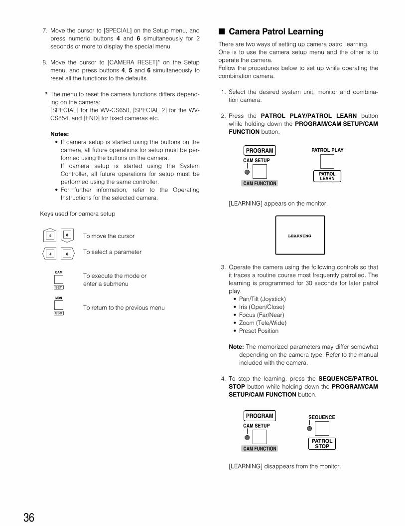
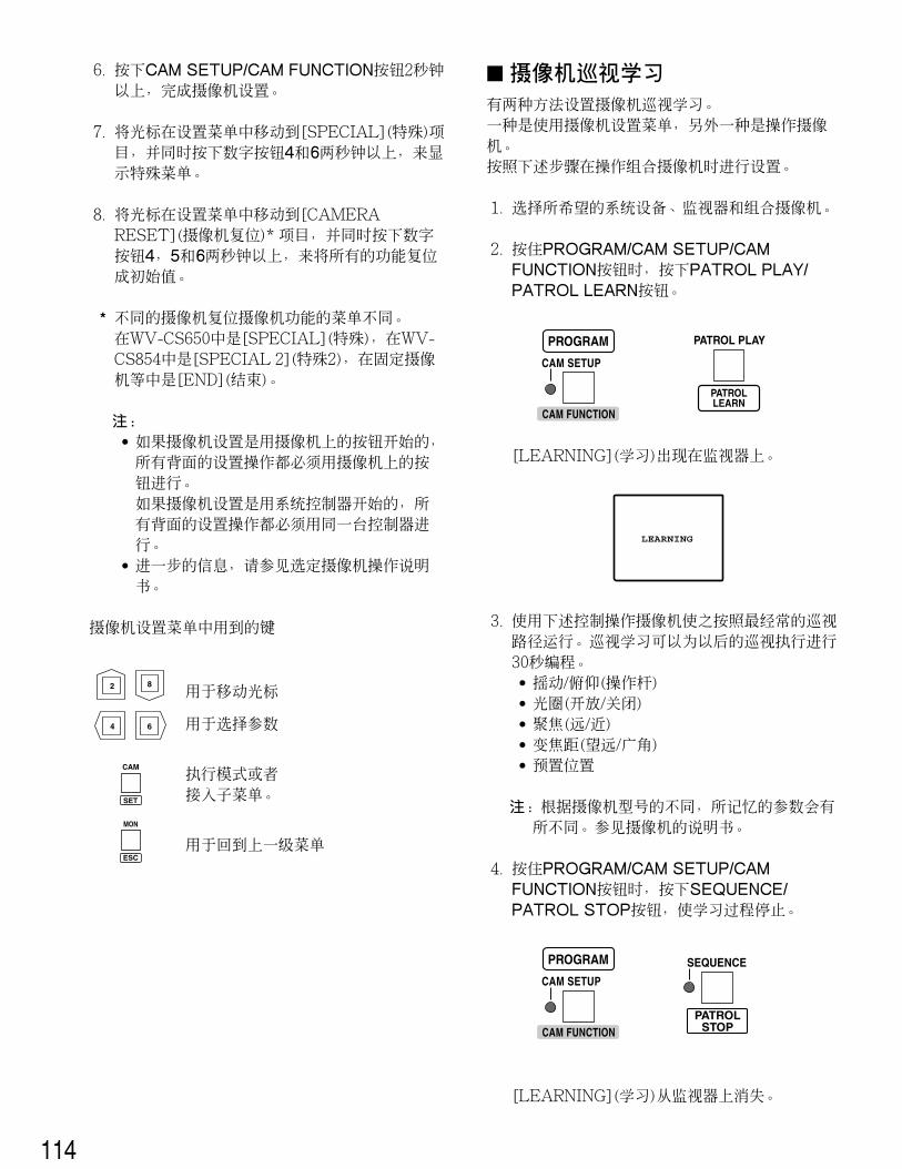
� Camera Patrol LearningThere are two ways of setting up camera patrol learning.One is to use the camera setup menu and the other is tooperate the camera.Follow the procedures below to set up while operating thecombination camera.
1. Select the desired system unit, monitor and combina-tion camera.
2. Press the PATROL PLAY/PATROL LEARN buttonwhile holding down the PROGRAM/CAM SETUP/CAMFUNCTION button.
[LEARNING] appears on the monitor.
3. Operate the camera using the following controls so thatit traces a routine course most frequently patrolled. Thelearning is programmed for 30 seconds for later patrolplay.
Note: The memorized parameters may differ somewhatdepending on the camera type. Refer to the manualincluded with the camera.
4. To stop the learning, press the SEQUENCE/PATROLSTOP button while holding down the PROGRAM/CAMSETUP/CAM FUNCTION button.
[LEARNING] disappears from the monitor.
7. Move the cursor to [SPECIAL] on the Setup menu, andpress numeric buttons 4 and 6 simultaneously for 2seconds or more to display the special menu.
8. Move the cursor to [CAMERA RESET]* on the Setupmenu, and press buttons 4, 5 and 6 simultaneously toreset all the functions to the defaults.
* The menu to reset the camera functions differs depend-ing on the camera:[SPECIAL] for the WV-CS650, [SPECIAL 2] for the WV-CS854, and [END] for fixed cameras etc.
Notes:• If camera setup is started using the buttons on the
camera, all future operations for setup must be per-formed using the buttons on the camera.If camera setup is started using the SystemController, all future operations for setup must beperformed using the same controller.
• For further information, refer to the OperatingInstructions for the selected camera.
Keys used for camera setup
LEARNING2 8
4 6
To move the cursor
To select a parameter
To execute the mode orenter a submenu
To return to the previous menu
CAM
SET
MON
ESC
CAM FUNCTION
CAM SETUP
PROGRAM
CAM FUNCTION
CAM SETUP
PROGRAM PATROL PLAY
PATROLLEARN
SEQUENCE
PATROLSTOP
37
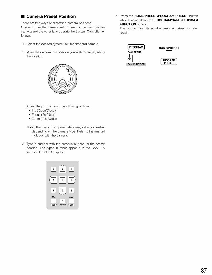
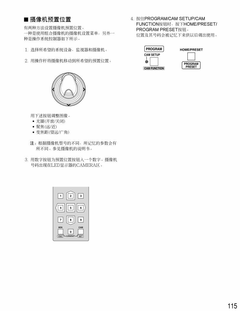
� Camera Preset PositionThere are two ways of presetting camera positions.One is to use the camera setup menu of the combinationcamera and the other is to operate the System Controller asfollows.
1. Select the desired system unit, monitor and camera.
2. Move the camera to a position you wish to preset, usingthe joystick.
Adjust the picture using the following buttons.• Iris (Open/Close)• Focus (Far/Near)• Zoom (Tele/Wide)
Note: The memorized parameters may differ somewhatdepending on the camera type. Refer to the manualincluded with the camera.
3. Type a number with the numeric buttons for the presetposition. The typed number appears in the CAMERAsection of the LED display.
4. Press the HOME/PRESET/PROGRAM PRESET buttonwhile holding down the PROGRAM/CAM SETUP/CAMFUNCTION button.The position and its number are memorized for laterrecall.
MON CAM
LOGOUTESC SET
HOME/PRESET
PROGRAMPRESETCAM FUNCTION
CAM SETUP
PROGRAM
38
39
For WJ-FS616CMultiplexer System
40
MAJOR OPERATING CONTROLS & THEIR FUNCTIONS
� Front View (Template for WJ-FS616C)
System ControllerOPERATE LOCK ALARM
SPOT
AUTO/+
IRIS
CLOSE OPEN
NEAR FAR
TELE WIDE
FOCUS
ZOOM
IRIS RESETVTRCAM
MULTISCREEN
SEQUENCE
EL-ZOOM MULTI SELECT
STILLPRE-POSI
ALT
ALM RESET
ALM SUSPEND
FUNCTION
ALL RESET
CAMERA SET
ON OFF ON/OFF
SETUPAUTO
FOCUS
HOME/-
UNIT CAM
ESC SET
R
DOWN
UNIT CAMERA
For Multiplexer
WV-CU CJ360
T/L MODE
CAMERA SITE CONTROL
AUX 2
AUX 1
!7!8!9
@0@1@2
@3@4@5
@6@7@8
@9#0
q w e r t y
u
io!0!1!2!3!4!5!6
q Operate Indicator (OPERATE)Is lit while power is supplied to the System Controller.
w Lock Indicator (LOCK)Is lit while operation of the System Controller and WJ-FS616C is prohibited by the connected computer. Thelock can be released by sending a command from thecomputer.
e Alarm Indicator (ALARM)Blinks when an alarm is activated. Blinking changes tosteady light when the alarm is automatically reset.To turn the indicator off, press the ALM RESET button.
r LED Display (UNIT CAMERA)LED display allowing you to confirm the number of thesystem unit and camera in operation. The CAMERAsection will display “–” when operating in multiscreen orsequence mode.
t Iris buttons (IRIS, CLOSE/OPEN)Close or open the lens iris of cameras equipped withthe specified lens.When these buttons are pressed at the same time, thelens iris is reset to the factory setting.
y Zoom wheel controllerThis control is used for zooming cameras equippedwith the specific lens. Moving the control to the right willzoom in the image. Moving the control to the left willzoom out the image.
u Joystick ControllerUsed to operate the pan/tilt head manually, or to movethe cursor to the desired position in the setup menu ofthe Video Multiplexer.
}: Upward{: Downward]: Left[: Right
i Top buttonPressing this button will automatically set the lens focusof a specified camera.
o Focus buttons (FOCUS, NEAR/FAR)Adjust the lens focus of cameras equipped with thespecified lens.
41
!0 Zoom buttons (ZOOM, TELE/WIDE)Zoom cameras equipped with the specified lens.
!1 Auto/Increment button (AUTO/+)Activates the auto panning function.During the setup, this button is used to select thedesired parameter in the setup menu.
!2 Home/Decrement button (HOME/–)Moves the camera to the home position.During the setup, this button is used to select thedesired parameter in the setup menu.
!3 Auto Focus button (AUTO FOCUS)Activates the auto focus function when the specifiedcamera with auto focus feature is selected.
!4 Camera/Set button (CAM/SET)CAM: Selects a camera. Enter a camera number with
the numeric buttons, then press the CAM/SET but-ton.
SET: Executes the currently highlighted setting in thesetup menu.
!5 Numeric Buttons (0 - 9)These buttons are used for numeric input into the sys-tem, such as the number of a camera you want toselect.
!6 Unit/Escape button (UNIT/ESC)UNIT: Selects a WJ-FS616C unit. Enter a unit number
with numeric buttons, then press the UNIT/ESC but-ton.
ESC: Escapes from the currently highlighted selectionand return to the previous menu window in thesetup.
!7 Alternate button (ALT)In combination with certain other buttons, activates spe-cial functions.For example, in combination with the ALM SUSPEND,EL-ZOOM or MULTI SELECT button, it is used to controlthe VTR (VCR).
!8 Multiscreen Monitor button (MULTI SCREEN)Selects the multiscreen monitor connected to the MUL-TISCREEN OUT connector of the Video Multiplexer.The indicator lights up when the multiscreen monitor isselected.Note: When REC OUT of the Video Multiplexer is used
as connector for the Multiscreen 2 Monitor, this but-ton alternately selects the Multiscreen orMultiscreen 2 Monitor.The indicator blinks when the Multiscreen 2 monitoris selected.
!9 Spot Monitor button (SPOT)Selects the spot monitor connected to the SPOT OUTconnector of the Video Multiplexer.The indicator lights up when the spot monitor is select-ed.
@0 Alarm Reset button (ALM RESET)Cancels an active alarm.Pressing this button while the alarm function is activat-ed will reset an alarm of the currently selected unit andreturn the system to the condition before the alarmfunction was activated.Pressing it in combination with the ALT button will resetall alarms.
@1 Sequence button (SEQUENCE)Activates the sequence mode. In this mode, a series ofcamera pictures is displayed in succession on the mon-itor screen for the specified duration.The indicator lights up when this mode is selected.
@2 VTR (VCR)/Camera selection button (VTR/CAM)Selects the camera picture or VTR (VCR) playback pic-ture for display on the multiscreen monitor.The indicator lights up when the VTR (VCR) mode isselected.Note: The above operation is not valid unless multi-
screen monitor is selected using the MULTI-SCREEN button.
@3 Alarm Suspend button (ALM SUSPEND)Pressing this button for more than two (2) seconds sus-pends activation of the alarm without changing the cur-rent alarm mode setup.The indicator lights up when the alarm suspensionmode is selected.
@4 Electronic Zoom button (EL - ZOOM)Zooms the picture presently displayed on the multi-screen monitor.
@5 Multiscreen Selection button (MULTI SELECT)Selects the multiscreen pattern to be displayed on themultiscreen monitor while monitoring the camera pic-ture or VTR (VCR) playback picture.Pressing this button repeatedly will switch the screen asfollows:Camera Picture:
@6 Function button (FUNCTION)Displays the VTR (VCR) playback picture with the cam-era pictures on the multiscreen monitor.The indicator lights up when the combined mode isselected, and turns off when the playback picture isselected.During the setup, this button is used to select the nextpage.
@7 Preset Position button (PRE - POSI)In combination with the numeric buttons and CAM(SET) button, moves the camera to the desired presetposition.
42
@8 Still button (STILL)Freezes the picture on the multiscreen monitor.The indicator lights up when the still mode is selected.
@9 Camera Set buttons (CAMERA SET ON/OFF)Open or close the camera setup menu on the monitorscreen.ON: Opens the selected camera setup menu on the
monitor, if applicable.The indicator lights up when the camera setupmenu is displayed.
OFF: Closes the camera setup menu.
#0 Set Up button (SET UP ON/OFF)Opens or closes the WJ-FS616/FS616C setup menu onthe monitor.
43
INSTALLATIONS (For WJ-FS616/FS616C)
The installation should be made by qualified service personnel or system installers according to the following instructions.
CAUTION
� System Connections� Connection ExampleThe connection example shows cameras and an alarm sensor connected to the Video Multiplexer. A time lapse VTR willrecord pictures for later playback. The spot monitor and multiscreen monitor will display live and playback pictures while thesedevices are being operated from System Controller WV-CU360CJ.
4
8
12
16
3
7
11
15
2
6
10
14
1
5
9
13
PUSH OPEN
16
POWER
LOCK
ON
OFF
ALARMMULTI
SCREENMULTISCREEN
SELECT
RESET SPOT SEQUENCE
VCRCAM
CAMERA/PRESET POSITION
Video
Data RS-485
Video MultiplexerWJ-FS616C
Time Lapse VCR
Personal Computer(Software)
System ControllerWV-CU360CJ
Spot MonitorLive 1-16ch
Multiscreen MonitorLive 1-16ch
Playback 1-16ch
RS-232C/Wired
Alarm Sensor
AUXAlarm
System ControllerOPERATE LOCK ALARM
SPOT
AUTO/+
IRIS
CLOSE OPEN
NEAR FAR
TELE WIDE
FOCUS
ZOOM
IRIS RESETVTRCAM
MULTISCREEN
SEQUENCE
EL-ZOOM MULTI SELECT
STILLPRE-POSI
ALT
ALM RESET
ALM SUSPEND
FUNCTION
ALL RESET
CAMERA SET
ON OFF ON/OFF
SETUPAUTO
FOCUS
HOME/-
UNIT CAM
ESC SET
UNIT CAMERA
For Multiplexer
WV-CU CJ360
T/L MODE
CAMERA SITE CONTROL
AUX 2
AUX 1
44
� DATA Port Connection (For Multiplexer)Data ports are connected with RS-485 cables among devices using the Camera Communication protocol as follows.
Note: When using cables other than those supplied, make sure to use shielded 4-wire twisted pair cable suitable for RS-485communication.
• Internal Diagram
• Basic Connection
� DIP Switch Setting (For Multiplexer)An 8-bit DIP switch mounted on the rear panel specifies the communication mode, etc. The default position is marked with anasterisk *.
System ControllerWV-CU360CJ
DATA
RS-485 Cable
Termination:ON
Termination:ON
TERM.
OFF
INOUT
ON
DATA
Video MultiplexerWJ-FS616C
DC 9V INDATAMODECONTROLLER No.
09
87 6 5 4
321
SW position
OFF
Not used
On*
On
Not used
Not used
FunctionON
Bit 1
Bit 2
Bit 3
Bit 4
Bit 5
Bit 6
Bit 7
Bit 8
Operation mode
Operation mode
Operation mode
Reserved
Line termination
Administrator mode
Reserved
Data transmission
See Unit Version*
See Unit Version*
See Unit Version*
Fixed to OFF*
Off
Off*
Fixed to OFF*
Fixed to OFF*
Data Flow
–
WJ-FS616C ← WV-CU360CJ
WJ-FS616C ← WV-CU360CJ
WJ-FS616C → WV-CU360CJ
WJ-FS616C → WV-CU360CJ
–
1
6
1
6
No. No.
1 1
2 2
3 3
4 4
5 5
6 6
Name
GND
TX(B)
TX(A)
RX(B)
RX(A)
GND
Controller endTX (B)
TX (A)
RX (A)
RX (B)
45
� Controller Number Setting Set this switch always to 1 when using the SystemController in a system including a Multiplexer WJ-FS616/FS616C.
� Switch Setting Procedures
1. Remove the DC plug from the rear of the controller.
2. Set the MODE switch referring to the table.• The bit switches #1 to #3 should be set to positions that
match the version of the Multiplexer installed in the sys-tem.
• Bit 5 opens or terminates the communication chain. Theswitch should be set to OFF when the controller is locat-ed in an intermediate position of the chain.
• Bit 6 specifies either Operator or Administrator as theAdministrator mode. Set to on when setting up the con-troller.
• Bits 4, 7 and 8 are reserved.
3. Set the CONTROLLER NO. switch to 1.
4. Connect the DC plug to the controller.
� Unit VersionThe unit ID is defined by the upper 3 bits depending on thesoftware version installed in the unit.
• WJ-FS616
• WJ-FS616C
MODE
1 2 3 4 5 6 7 8
OFF
ON
MODE
1 2 3 4 5 6 7 8
OFF
ON
09
87 6 5 4
321
CONTROLLER No.
46
SETUP PROCEDURES (For WJ-FS616/FS616C)
To display the setup menus for the WV-CU360CJ System Controller on the LED display, set the MODE switch and power upthe controller as described below.
� Prior to SetupDo the following before entering the setup mode.
1. Confirm that all necessary connections and switch set-tings are complete.
2. With the power turned off, move bit #6 of the MODEswitch on the rear to ON (administrator) position.
3. Supply power to the controller.
4. Turn on the power of cameras and other system units.
5. The LCD displays [SEtUP]. The controller is ready toenter the setup mode.
When setup is completed, restore the switch to its originalposition.
1. With the power turned off, move bit #6 of the MODEswitch on the rear to OFF (operator) position.
2. Supply power to the controller.
� Buttons and Controls Used for SetupThe following buttons and joystick operations are used forsetup.
0 9 Numeric buttons: To select a parameter
CAM/SET button: To execute modes andparametersTo enter a submenu
UNIT/ESC button: To return to the previousmenu
CAM
SET
UNIT
ESC
Up: To select a setup menu
Down: To select a setup menu
Left: To decrease the parameter
Right: To increase the parameter
HOME/-
AUX 1
AUTO/+
AUX 2
or
or
48
� Controller Setup Set up the baud rate and parity check mode for the controller while observing the LED on the front panel.
� Administrator Authorization1. Press the CAM/SET button while [SEtUP] is displayed.
The [- - - - -] prompt appears.
2. Enter a password with the numeric buttons, then pressthe CAM/SET button.The default setting is [12345].
3. If the password entered is valid, [SPEED] appears. Ifpassword entry failed, the menu returns to [SEtUP].
� Baud RateIn this menu, the communication speed (bps: bits per sec-ond) is selected. The communication speed should matchthat of the WJ-FS616/FS616C.
1. Display [SPEED] and press the CAM/SET button twice.
2. Select a parameter entering a bracket-enclosed num-ber, e.g., (3), moving the joystick to right and left, orpressing the [+] and [–] buttons.The default setting is 9 600 bps.
Note: Selecting a slower rate (e.g., 2 400 bps) will delaythe response time (e.g., the time until an activatedalarm is reset).
3. Press the CAM/SET button to validate the selection.
4. Press the ESC button to go back to the previous menu.
Menu Selection
Move Joystick up and down to select
Setup MenusParameter Selection (default*)
LED Display
blinking
Setup
AdministratorPassword
Prompt
Speed
Parity
InitialDisplay
Authorization
Baud Rate(bps)
Presstwice
Parity Check
CAM
SET
CAM
SET
MON
ESC
LED prompts you to enter pass-word
Enter a 5-digit password, press (12345*)
(1) 2 400 (2) 4 800 (3) 9 600*(4) 19 200
(1) None (2) Even*
Reading Function
OK
No
CAM
SET
48
� ParityIn this menu the parity check mode is selected.
1. Display [PrtY] and press the CAM/SET button twice.
2. Select a parameter with the joystick.The default setting is Even.
n: NoneE: Even parity
3. Press the CAM/SET button to validate the selection.
4. Press the ESC button to go back to the previous menu.
49
OPERATING PROCEDURES (For WJ-FS616/FS616C)
� Camera SelectionOne of the cameras connected to the system unit is select-ed.
1. Enter a camera number using the numeric buttons.The number appears on the LED display.
2. Press the CAM/SET button.
Note: [--] appears in the camera section of the LED dis-play when an alarm is activated, when the multi-screen is displayed, or when sequence mode isrun.
The following functions of the camera are controlled.• Pan/tilt• Focus• Zoom• Iris• Defroster ON/OFF (camera housing)• Wiper ON/OFF (camera housing)• Preset Position (Combination Camera)• Home position (Combination Camera)• Auto pan (Combination Camera)
The following additional functions can be controlled whenusing the WV-CS854 or later camera models.
• Switching between colour and B/W picture(Combination Camera)
• Patrol Learn function (Combination Camera)• Camera functions (Combination Camera)
� Camera ControlCameras and their peripherals are controlled from the WV-CU360CJ as follows. Some of the descriptions may not beapplicable if they refer to devices not equipped in your sys-tem.
� Pan/Tilt ControlProceed as follows to control an ordinary camera mountedon a pan/tilt head or a combination camera in manual orautomatic panning mode.
1. Move the pan/tilt head in the desired direction with thejoystick controller.
2. Press the AUTO/+ button to activate a preset auto pan-ning.
� AUX ControlThis allows you to control an auxiliary device such as abuzzer or lamp connected to the Receiver or combinationcamera.
8 Auxiliary 1/21. Press the ALT button to turn on the ALT indicator .
2. Press the AUX 1 or AUX 2 button to operate or cancelthe auxiliary function for the selected camera.
Note: For common operations to the controller and the WJ-FS616/FS616C, please refer to the manual included with theWJ-FS616/FS616C. The following pages describe only operations different from the WJ-FS616/FS616C.
UNIT CAM
ESC SET
CAM
SET
ALTAUTO/+
HOME/-
AUX 2
AUX 1
50
Note: Auxiliary control may be ignored while zooming,focusing or panning/tilting is in operation.
� Alarm OperationWhen the WV-CU360CJ receives an alarm signal from theWJ-FS616/FS616C, the alarm indicator blinks. The alarmindicator changes from blinking to steady light when thealarm is automatically reset. The camera number appearsin the camera section of the LED display.
� Alarm Reset1. Press the ALM RESET button while the ALT indicator is
not lit. An activated alarm is reset and the alarm indica-tor on the controller goes off.
2. To reset all alarms issued by the multiplexers connect-ed in a daisy chain, press the ALT button, then pressthe ALM RESET buttons.
� Alarm Suspension1. Press the ALM SUSPEND button for more than 2 sec-
onds to suspend the alarm. The ALM SUSPEND indi-cator lights up.
2. Press the ALM RESET button to reset alarm suspen-sion. The ALM SUSPEND indicator goes off.
� VTR (VCR) ControlYou can operate a VTR (VCR) connected to the VideoMultiplexer from the controller using the buttons listedbelow with the ALT indicator lit.
Function
Rewind
Pause
Fast Forward
Reverse Play
Stop
Playback
T/L (time-lapse) ModeDown
Up
Recording
Logo Note
e.g., change from 72H modeto 24H mode
e.g., change from 24H modeto 72H mode
ALM RESET
ALL RESET
ALM RESET
ALL RESET
ALM SUSPEND
51
� Camera SetupThe cameras connected to the WJ-FS616/FS616C are setup from the controller.
Note: Make sure that the multiplexer and the controllerare set to identical communication parameters.
� General Setup
1. Select a camera pressing the numeric buttons, thenpress the CAM/SET button.
2. Press the CAMERA SET ON button. The ON indicatoris lit while the CAMERA SET UP MENU is displayed onthe monitor.
3. Select a setup item by moving the joystick up anddown. Select a parameter by moving the joystick to theright or left, then press the CAM/SET button to validatethe selection or to enter a submenu.
4. Press the UNIT/ESC button to execute the selectionand to return the menu to a higher layer.
5. Press the SEQUENCE button to enter the SPECIALmenu.
6. Press the VTR/CAM button to reset all functions to thedefaults, or press the SEQUENCE button to reset aselected function.
7. Press the CAMERA SET OFF button to close the cam-era setup menu.
� Shortcut for Preset Position SetupA shortcut can be created for setting a camera positionwithout going through the whole presetting process.Shortcuts are applicable only to cameras having the preset-ting function.
1. Open the PRESET menu of the camera.
2. Press the ALT button while the position setting menu isdisplayed.
3. Move the camera with the joystick to the position youwish to preset.
4. Adjust the picture with the IRIS, FOCUS and ZOOMbuttons.
5. Press the ALT button again. The preset conditions areregistered, and the joystick function reverts to movingthe cursor.
CAMERA SET
ON OFF
T/L MODE
CAM
SET
UNIT
ESC
SEQUENCE
VTRCAM
CAMERA SET
ON OFF
T/L MODE
52
53
For System 850WJ-SX850 MatrixSwitcher System
54
MAJOR OPERATING CONTROLS & THEIR FUNCTIONS
� Front View (Template for System 850 Matrix Switcher)
q Operate indicator (OPERATE)Is lit while power is supplied to the System Controller.
w Link indicator (LINK)Lights up when communication is established with theMain CPU.
e Alarm indicator (ALARM)Lights up when an alarm condition exists. Select thealarm number using the numeric buttons, then pressthe ALARM button and the RESET button to turn off theindicator.
r Monitor indicator (MONITOR)Lights up when the monitor number is displayed on theLED display.
t LED DisplayDisplays the number of monitors and cameras currentlycontrolled.It also displays numeric input, error status, etc.
y Camera indicator (CAMERA)Lights up when the camera number is displayed on theLED display.
u Busy indicator (BUSY)Lights up when you attempt to control a monitor or cam-era that is already used by a higher priority operator, orwhen the higher priority operator selects the camera ormonitor you are currently operating.Operations from the System Controller are disableduntil this indicator goes off.
i Prohibited indicator (PROHIBITED)This indicator lights up for 3 seconds when an attemptis made to gain access to a function that is prohibitedby the partition.
o Zoom wheel controllerThis control is used for zooming cameras equippedwith the specific lens. Moving the control to the right willzoom in the image. Moving the control to the left willzoom out the image.
AUTO FOCUS
OPERATE LINK ALARM BUSY PROHIBITED
IRIS
CLOSE OPEN
NEAR FAR
WIDE TELE
FOCUS
ZOOM
IRIS RESET
PREV
SEQSEQTOURGROUP
ALARM
DISARM
ACK RESET
GROUP PRESET NEXT
LOG OUT PAUSE STOP
F1
F2 MONITOR
CAM FUNC LOCKOSD SERVICE
CAMERA(ENTER)
CLEAR(ESC)
CALLPRESET
PROGRAMPRESET
SHIFT
DEF OFF DEF ON
AUX2 OFF AUX2 ON
AUX1 OFF AUX1 ON
CAM IDT&D
OPE ID S-CTL ID
OSD
CAM MENU OFF CAM MENU ON
ALL RESET
MDN STATUS
WIPER
GEN
ALL
EXITBLK
VLD HALM H
VLD S SYS SALM S
AUTOPAN
MONITOR CAMERA
For Matrix Switcher (System 850)
WV-CU CJ360System Controller
@1@2@3
@4@5@6
@7@8@9
#0
q w e tr y u i o
!0
!1!2!4!3!5!6!7!8!9@0#4#3#1 #2
55
!0 Joystick ControllerUsed to manually operate the Pan/Tilt Head, or movethe cursor in the camera menu on the active monitorscreen.
}: Upward{: Downward]: Left[: Right
!1 Top buttonPressing this button will automatically set the lens focusof a specified camera.
!2 Iris buttons (IRIS, CLOSE/OPEN)Closes or opens the lens iris of cameras equipped withthe specified lens.When these buttons are pressed at the same time, thelens iris is reset to the factory default setting.
!3 Focus buttons (FOCUS, NEAR/FAR)Adjusts the lens focus of cameras equipped with thespecified lens.When these buttons are pressed at the same time, thelens focus is set automatically if the specified camerawith the auto focus feature is equipped.
!4 Zoom buttons (ZOOM, WIDE/TELE)Zoom the image in or out if the camera is equipped withthe specified lens.
!5 Program Preset button (PROGRAM PRESET)In combination with the numeric buttons and CAMERA(ENTER) button, saves a preset position of the camerain a system equipped with the specified cameras.To save a preset position, move the camera to the posi-tion to be preset and select a preset number by press-ing the numeric buttons. Hold down the PROGRAMPRESET button, then press the CAMERA (ENTER) but-ton.
!6 Call Preset button (CALL PRESET)In combination with the numeric buttons, moves thepan/tilt head of the selected camera to a preset positionin a system equipped with the specified cameras.
!7 Camera/Enter button [CAMERA (ENTER)]CAMERA: Used for camera selection. Select a camera
by pressing the corresponding numeric buttons, fol-lowed by the CAMERA (ENTER) button.
ENTER: In combination with the numeric buttons, enternumeric input, such as operator ID and password.It is also used to execute the currently highlightedselection and enter a submenu of the cameramenu.
Pressing CAMERA (ENTER) while holding down theSHIFT button will activate the auto panning function ofthe selected camera (AUTO PAN).
!8 Clear/Escape button [CLEAR (ESC)]CLEAR: Clears numeric input from the LED display.ESC: Escapes from the currently highlighted selection
and return to the previous page of the cameramenu.
This button is also used to exit from alarm selectionmode to normal operation mode.
!9 Numeric buttons (0 - 9)Used for numeric input into the system such as thecamera and monitor number, sequence number, presetposition, etc.Pressing the buttons shown below while holding downthe SHIFT button will select special functions.
1: Turns off the user auxiliary 1 switch of the receiver.(AUX1 OFF)
2: Turn on the user auxiliary 1 switch of the receiver.(AUX1 ON)
3: Turns on the housing wiper of the camera untilthese buttons are released. (WIPER)
4: Turns off the user auxiliary 2 switch of the receiver.(AUX2 OFF)
5: Turns on the user auxiliary 2 switch of the receiver.(AUX2 ON)
7: Turns off the housing defroster of the camera. (DEFOFF)
8: Turns on the housing defroster of the camera. (DEFON)
@0 Shift button (SHIFT)Pressing this button in combination with buttons towhich a special function has been assigned will acti-vate these functions.
@1 Alarm button (ALARM), Disarm indicator (DISARM)In combination with the Numeric buttons, selects analarm. To select an activated alarm, press the numericbuttons, followed by the ALARM button.Pressing this button repeatedly enables or disables thecameras and monitor assigned to perform the alarmactivities.The DISARM indicator next to the button is lit whilealarm activities are disabled.
@2 Alarm Acknowledge button (ACK)Acknowledge an activated alarm. Select the alarm bypressing the numeric buttons, followed by the ALARMbutton. Select the desired alarm action number bypressing the numeric buttons, then press the ACK but-ton. The ACK indicator will light.After acknowledging the alarm, press the RESET buttonto reset the alarm. The ACK indicator will go off.
56
@3 Alarm Reset button (RESET)Cancels an activated alarm.Press this button to reset an alarm activated in the cur-rently active unit.Pressing this button while holding down the SHIFT but-ton cancels all currently activated alarms at a time (ALLRESET).Pressing RESET in the camera menu will reset the para-meter of a selected item or open the Special cameramenu when the cursor is positioned on SPECIAL in themenu. Pressing it while holding down the SHIFT buttonwill restore all factory default settings.
@4 Group Preset button (GROUP PRESET)In combination with the numeric buttons, activates apreviously programmed Group Preset function.Pressing this button while holding down the SHIFT but-ton will display the Operator ID number on the LEDDisplay for about 3 seconds (OPE ID).
@5 Previous button (PREV)Moves a Tour Sequence one step backward from thestep that was previously paused on the active monitorby pressing the PAUSE button.This button is also used to select a camera. PressingPREV while holding down the CAMERA (ENTER) buttonwill replace the currently selected camera with the nextlower camera number, if the active monitor is in Spotmode.Similarly pressing PREV while holding down the MONI-TOR button will select the next lower monitor number.When selecting alarms, pressing PREV while holdingdown the ALARM button will select the previous alarm.Pressing this button while holding down the SHIFT but-ton will display the Controller ID number on the LEDDisplay for about 3 seconds (S-CTL ID).
@6 Next button (NEXT)Moves a Tour Sequence one step forward from the stepthat was previously paused on the active monitor bypressing the PAUSE button.The button is also used to select a camera. PressingNEXT while holding down the CAMERA (ENTER) buttonwill replace the currently selected camera with the nexthigher camera number, if the active monitor is in Spotmode.Similarly pressing NEXT while holding down the MONI-TOR button will select the next higher monitor number.When selecting alarms, pressing NEXT while holdingdown the ALARM button will select the next alarm.
@7 Log Out button (LOG OUT)In combination with the CAMERA (ENTER) button, logsout from the system.To prevent a log-out error, press CAMERA (ENTER)while holding down the LOG OUT button.
@8 Pause button (PAUSE)Pauses a Tour or Group Sequence that is being run onthe active monitor.Pressing PAUSE while holding down the SHIFT buttonwill close the camera menu on the active monitor. TheSTOP indicator will go off. (CAM MENU OFF)
@9 Stop button (STOP)Ends a Tour Sequence that is being run on the activemonitor.To end a Group Sequence, select one of the monitorsthat displays the selected sequence, then press thisbutton.Pressing STOP while holding down the SHIFT buttonwill open the camera menu on the active monitor. TheSTOP indicator will light. (CAM MENU ON)
#0 Function buttons (F1, F2)Provide access to camera attributes and operatingfunctions.
F1: Reserved for future use.F2: Pressing this button will select the mode for control-
ling selected camera functions (CAM FUNC).
#1 Group Sequence button (GROUP SEQ)In combination with the numeric buttons, runs a GroupSequence on the assigned monitors.Pressing GROUP SEQ will restart a forward sequencefrom the next step that was previously paused bypressing the PAUSE button.
#2 Tour Sequence button (TOUR SEQ)In combination with the numeric buttons, runs a TourSequence on the active monitor.Pressing TOUR SEQ will restart a forward sequencefrom the next step that was previously paused bypressing the PAUSE button.
#3 OSD (On Screen Display) button (OSD)Displays or hide some of the information on the screenof the selected monitor. Press the numeric buttonsshown below, then press the OSD button.
1: Clock Display (T&D)2: Camera Title Display (CAM ID)3: General Status Display (GEN)5: Monitor Status Display (MON STATUS)6: All Displays except clock (ALL)
57
#4 Monitor/Monitor Lock/OSD service button(MONITOR/OSD SERVICE), Lock indicator (LOCK)Selects a monitor by entering a monitor number with thenumeric buttons, and then pressing this button.To lock or unlock the currently selected monitor, pressthis button while holding down the SHIFT button. Whilethe LOCK indicator is lit, other operators will be barredfrom accessing the monitor.To access OSD service, press the numeric buttonsshown below, then press this button.
1: ALMS, Alarm status2: VLDS, Video loss detection status3: SYS S, System status4: ALM H, Alarm history5: VLDH, Video loss detection history
58
INSTALLATIONS (For System 850)
The installation should be made by qualified service personnel or system installers according to the following instructions.
CAUTION
� System Connections� Connection ExampleThe connection example shows a large-scale system having a number of cameras, alarm sensors, monitors and so forth con-nected to the System 850 Matrix Switcher. The System Controller WV-CU360CJ provides major operating functions to control the system.
Cameras Combination Cameras
Video Monitors
Time Lapse VCRs
Sensors
System 850Matrix Switcher
System Controllers
AUTO FOCUS
OPERATE LINK ALARM BUSY PROHIBITED
IRIS
CLOSE OPEN
NEAR FAR
WIDE TELE
FOCUS
ZOOM
IRIS RESET
PREV
SEQSEQTOURGROUP
ALARM
DISARM
ACK RESET
GROUP PRESET NEXT
LOG OUT PAUSE STOP
F1
F2 MONITOR
CAM FUNC LOCKOSD SERVICE
CAMERA(ENTER)
CLEAR(ESC)
CALLPRESET
PROGRAMPRESET
SHIFT
DEF OFF DEF ON
AUX2 OFF AUX2 ON
AUX1 OFF AUX1 ON
CAM IDT&D
OPE ID S-CTL ID
OSD
CAM MENU OFF CAM MENU ON
ALL RESET
MDN STATUS
WIPER
GEN
ALL
EXITBLK
VLD HALM H
VLD S SYS SALM S
AUTOPAN
MONITOR CAMERA
For Matrix Switcher (System 850)
WV-CU CJ360System Controller
59
DC 9V INDATAMODECONTROLLER No.
09
87 6 5 4
321
DC 9V INDATAMODECONTROLLER No.
09
87 6 5 4
321
DC 9V INDATAMODECONTROLLER No.
09
87 6 5 4
321
DC 9V INDATAMODECONTROLLER No.
09
87 6 5 4
321
PARALLELSATELLITEMODE
REDUNDANTCPU
ETHERNET
1
CAMERACROSS POINT
OSD
SYSTEMCONTROLLER
DATA 6 DATA 5 DATA 4 DATA 3 DATA 2 DATA 1
PERIFERAL INTERFACE (RS–232C)
(RS–485)SYSTEMCONTROLLER
23
SATELLITESTANDALONE
YESNO
AC IN
Central Processing Unit
125V 3.0A
SIGNALGND
Main CPU
� DATA Port ConnectionData ports are connected with RS-485 cables among devices using Camera Communication protocol as follows.Note: When using cables other than those supplied, make sure to use shielded 4-wire twisted pair cable suitable for RS-485
communication.
• Internal Diagram
• Basic Connection
Data Flow
–
Main CPU ← WV-CU360CJ
Main CPU ← WV-CU360CJ
Main CPU → WV-CU360CJ
Main CPU → WV-CU360CJ
–
1
6
1
6
No. No.
1 1
2 2
3 3
4 4
5 5
6 6
Name
GND
TX(B)
TX(A)
RX(B)
RX(A)
GND
Controller endTX (B)
TX (A)
RX (A)
RX (B)
60
� Controller Number SettingSet this switch always to 1 when using the SystemController in a System 850.
� Switch Setting ProceduresSet the MODE DIP switch and CONTROLLER NO. switch asfollows.
1. Remove the DC plug from the rear of the controller.
2. Set the switches as follows.
• Bit 1 should be set to OFF*.• Bit 2 should be set to ON.• Bit 3 should be set to OFF*.• Bit 4 should be set to OFF*.• Bit 5 should be set to ON* when connecting with a
System 850 in a home run (one to one) fashion.• Bit 6 should be set to OFF* normally, or ON
(Administrator mode) when setting up the controller.• Bit 7 should be set to ON. The baud rate is selected in
the controller setup.• Bit 8 should be set to OFF* normally.
3. Connect the DC plug to the controller.
SW position
OFF
See below
See below
See below
Not used
On*
On
Fixed to ON
3 times
FunctionON
Bit 1
Bit 2
Bit 3
Bit 4
Bit 5
Bit 6
Bit 7
Bit 8
Operation mode
Operation mode
Operation mode
Reserved
Line termination
Administrator mode
Baud Rate Selection
Repeat Transmissions
*
*
*
*
Off
Off*
Not used
1 time*
MODE
1 2 3 4 5 6 7 8
OFF
ON
09
87 6 5 4
321
CONTROLLER No.
� DIP Switch SettingAn 8-bit DIP switch mounted on the rear panel specifies communication mode, etc. The default position is marked with anasterisk *.
DC 9V INDATAMODECONTROLLER No.
09
87 6 5 4
321
61
SETUP PROCEDURES (For System 850)
To display the setup menus for the WV-CU360CJ System Controller on the LED display, set the MODE switch and power upthe controller as described below.
� Prior to SetupDo the following before entering the setup mode.
1. Confirm that all necessary connections and switch set-tings are complete.
2. With the power turned off, move bit #6 of the MODEswitch on the rear to ON position (Administrator mode).
3. Supply power to the controller.
4. Turn on the power of cameras and other system units.
5. The LCD displays [SEtUP]. The controller is ready toenter the setup mode.
When setup is completed, restore the switch to its originalposition.
1. With the power turned off, move bit #6 of the MODEswitch on the rear to OFF position.
2. Supply the power to the controller.
� Buttons and Controls Used for SetupThe following buttons and joystick operations are used forsetup.
DC 9V IN
To an AC outlet
AC adapter
Power cord
DC 9 V plug
MODE
1 2 3 4 5 6 7 8
OFF
ON
MODE
1 2 3 4 5 6 7 8
OFF
ON
Operator mode
Administrator mode
0 9 Numeric buttons: To select a parameter
CAM (ENTER) button: To execute modesand parametersTo enter a submenu
CLEAR (ESC) button: To return to the previ-ous menu
CAMERA(ENTER)
AUTOPAN
Up: To select a setup menu
Down: To select a setup menu
Left: To decrease the parameter
Right: To increase the parameter
CLEAR(ESC)
EXIT
62
� Setup ProceduresSet up the baud rate and parity check mode for the controller while observing the LED on the front panel.
Menu Selection
Move Joystick up and down to select
Setup MenusParameter Selection (default*)
LED Display
blinking
Setup
AdministratorPassword
Prompt
Speed
Parity
InitialDisplay
Authorization
Baud Rate(bps)
Presstwice
Parity Check
CAM
SET
CAM
SET
MON
ESC
LED prompts you to enter pass-word
Enter a 5-digit password, press (12345*)
(1) 2 400 (2) 4 800 (3) 9 600*(4) 19 200
(1) None* (2) Even
Reading Function
OK
No
CAM
SET
� Administrator Authorization1. Press the CAMERA (ENTER) button while [SEtUP] is
displayed. The [- - - - -] prompt appears.
2. Enter a password using the numeric buttons, then pressthe CAMERA (ENTER) button.The default setting is [12345].
3. If the password entered is valid, [SPEED] appears. Ifpassword entry failed, the menu returns to [SEtUP].
� Baud RateIn this menu, the communication speed (bps: bits per sec-ond) is selected. The communication speed should matchthat of the WJ-SX850.
1. Display [SPEED], and press the CAMERA (ENTER)button twice.
2. Select a parameter entering a bracket-enclosed num-ber, e.g., (3), moving the joystick.The default setting is 9 600 bps.
Note: Selecting a slower rate (e.g., 2 400 bps) willdelay the response time (e.g., the time until an acti-vated alarm is reset).
3. Press the CAMERA (ENTER) button to validate theselection.
4. Press the CLEAR(ESC) button to return to the [SPEED]menu.
� ParityIn this menu, the parity check mode is selected.
1. Display [PrtY] and press the CAMERA (ENTER) buttontwice.
2. Select a parameter with the joystick.The default setting is None.
n: NoneE: Even parity
3. Press the CAMERA (ENTER) button to validate theselection.
4. Press the CLEAR(ESC) button to return to the [SPEED]menu.
Note: The baud rate and parity check mode of the WJ-SX850 and the controller must be the same, otherwisedata communications will not function.
63
OPERATING PROCEDURES (For System 850)
� Log-in & Log-out� Log-in
1. Turn on the power switches of all system components.
2. Turn on the power of the WV-CU360CJ SystemController by connecting the AC adapter to the AC out-let.The OPERATE indicator lights up and “NO USER” willappear on the LED display of the System Controller.
3. Enter your registered Operator ID number (up to 5 dig-its) using the numeric buttons, then press the [CAM-ERA (ENTER)] button. The underline appears on theLED display.
4. Enter your registered Password (up to 5 digits) usingthe numeric buttons, then press the [CAMERA(ENTER)] button.If the operator ID and password entered are valid, theLED will display “READY”.
Note: If login has failed (operator or password error), thePROHIBITED indicator on the controller will light up and“NO ACCESS” will blink on the LED display for about 3seconds. Then the login procedure returns to the start.
� Log-out
1. While holding down the LOG OUT button, press the[CAMERA (ENTER)] button .
“NO USER” is displayed on the LED display.
PROGRAMPRESET
CALLPRESET
AUX1 OFF
CAM ID
AUX1 ON
GEN
WIPER
AUX2 OFF
MON STATUS
AUX2 ON
ALL
SHIFTCLEAR(ESC)
DEF OFF DEF ONCAMERA(ENTER)
AUTOPAN
1 2 3
4 5 6
7 8
0
9
PROGRAMPRESET
CALLPRESET
AUX1 OFF
CAM ID
AUX1 ON
GEN
WIPER
AUX2 OFF
MON STATUS
AUX2 ON
ALL
SHIFTCLEAR(ESC)
DEF OFF DEF ONCAMERA(ENTER)
AUTOPAN
1 2 3
4 5 6
7 8
0
9
LOG OUTCAMERA(ENTER)
AUTOPAN
Note: This section describes only some important operations such as log-in, log-out, and different operations from the frontpanel of the System 850. Please refer to the manual included with the System 850 for further information on cameraselection, monitor selection and so forth.
64
65
For WJ-SX150Matrix Switcher System
66
SETUP SHIFT
REW/FF
STEP
AUTO FOCUS
OPERATE LINK ALARM BUSY PROHIBITED
CALLPRESET
PROGRAMPRESET
IRIS
CLOSE OPEN
NEAR FAR
WIDE TELE
FOCUS
ZOOM
AUTO IRIS
GROUP SEQ
PAUSE
SUSPEND
F1
CAM SETUP ALL RESET
ACK RESET
F2 TOUR SEQ
PREV NEXT
STOP
OSD
AUTO PAN
MONITOR CAMERA
For Matrix Switcher (WJ-SX150)
WV-CU CJ360System Controller
RECORDER
INDEX
STOP PLAY
REC
PAUSE
CAM FUNC
CLEAR
LOG OUTMON LOCK
DEF ON
WIPER
DEF OFF
MON (ESC)
T&D CAM ID
MON STATUS ALL
EVENT
ALM H VLD H SYS S
CAM (SET)
MULTI SCREEN SEL
SEQUENCE
AUX2 ONAUX2 OFFEL-ZOOM
AUX1 ONAUX1 OFFSTILL
q y u i ow e r t
@1
@2
#2
#5 #1 #4 !1!8!9@0#3#0 !6!7 !5 !4 !3!2
@3
@4@6@5
@9
@8
@7 !0
MAJOR OPERATING CONTROLS & THEIR FUNCTIONS
� Front View (Template for WJ-SX150)
q Operation indicator (OPERATE)Lights up when the controller's power is turned on.
w Link indicator (LINK)Lights up when communication is established with thematrix switcher.
e Alarm indicator (ALARM)Lights up when an alarm condition exists.
r Monitor indicator (MONITOR)Lights up when the monitor number appears on theLED display.
t LED DisplayDisplays the monitor number, camera number, numericentry and error status, etc.
y Camera indicator (CAMERA)Lights up when the camera number appears on theLED display.
u Busy indicator (BUSY)Lights up when the higher-priority operator selects thecamera or monitor you are currently operating.Operations from the system controller are disabled untilthis indicator goes off.
i Prohibited indicator (PROHIBITED)Blinks when an operator attempts to control a monitor(or camera) that is already used by a higher-priorityoperator or the operator has done the prohibited opera-tion.
o Zoom wheel controllerThis control is used for zooming cameras equippedwith the specific lens. Moving the control to the right willzoom in the image. Moving the control to the left willzoom out the image.
67
!0 JoystickUse this joystick to manually operate cameras, camerasite accessories and a recorder, or to move the cursorin SETUP MENU on the active monitor screen.
}: Up{: Down]: Left, rewind*, backward field advance*[: Right, fast-forward*, forward field advance*
*Available after pressing the RECORDER button whileconnecting to a recorder.
!1 Top buttonPressing this button will automatically set the lens focusof a specified camera.
!2 Iris buttons (IRIS CLOSE/OPEN)Close or open the lens iris of cameras equipped withthe specified lens.Press the CLOSE and OPEN buttons simultaneously.The lens iris is reset to the factory default setting.
!3 Focus buttons (FOCUS NEAR/FAR)Adjust the lens focus of cameras equipped with thespecified lens.Press the NEAR and FAR buttons simultaneously. Thelens focus is adjusted automatically, if the specifiedauto focus camera is equipped.
!4 Zoom buttons (ZOOM WIDE/TELE)Press these buttons to zoom the lenses equipped withthe specified cameras.Press the WIDE and TELE buttons simultaneously. Therecording is started.
!5 Call Preset button (CALL PRESET/PROGRAMPRESET)To program the selected camera's preset position,press this button in combination with the numeric but-tons. (The specified cameras support this function.)
!6 Auto Pan button (AUTO PAN/CAM FUNC)Activates the auto panning function of camerasequipped with this feature.To execute camera functions, press this button in com-bination with the numeric buttons. (The specified cam-eras support this function.)
!7 Clear button (CLEAR/LOG OUT)Use this button to clear numeric input on the LED dis-play, or exit from the ALARM HISTORY table, the VIDEOLOSS HISTORY table, or the SYSTEM STATUS table.To logout of the system, press this button while holdingdown the SHIFT button.
!8 Camera (Set) button [CAM (SET)/WIPER]CAM: To select a camera, press the corresponding
numeric button, followed by this button.SET: To enter numeric input, such as operator ID and
password, press this button in combination with thenumeric buttons.Also use this button to execute the currently high-lighted selection and go into a submenu of SETUPMENU.
WIPER: To turn on the housing wiper of the camera,press this button while holding down the SHIFT but-ton.
!9 Numeric buttons Press these buttons to enter numbers into the systemsuch as the camera and monitor number, sequencenumber, preset position, etc.• In combination with the SHIFT button, parameter
selection in OSD (On-screen Display), operation ofthe monitor status or search in a history tablebecome available.
• In combination with the RECORDER button, electron-ic zooming and multiscreen sequence are available.
@0 Monitor (Escape) button [MON (ESC)/MON LOCK]MON: Press this button to select a monitor.
To select a monitor, press the correspondingnumeric buttons, followed by the MON (ESC) but-ton.
ESC: Press this button to escape from the currentlyhighlighted selection and return to the previouspage of SETUP MENU.
MON LOCK: To prevent other operators from control-ling the monitor, press this button while holdingdown the SHIFT button. To release the lock, pressthis button while holding down the SHIFT buttonagain.
@1 Alarm Reset button (RESET/ALL RESET)RESET: To reset an alarm activated in the currently
active monitor, press this RESET button.ALL RESET: To cancel all activated alarms at a time,
press this button while holding down the SHIFT but-ton.
@2 Alarm Acknowledge button (ACK/SUSPEND)ACK: Acknowledges an activated alarm.
To select the alarm monitor, press the ALARM but-ton.To select the desired alarm action number, pressthe numeric buttons, then press this ACK button."ACK" will appear on the monitor.To reset the alarm, press the RESET button afteracknowledging the alarm. "ACK" will go out.
SUSPEND: To suspend an activated alarm, press thisbutton while holding down the SHIFT button. "ALMSUSPENDED" will appear on the monitor. To cancelthe suspension, press this button while holdingdown the SHIFT button again.
68
@3 Function 1 button (F1/CAM SETUP)Press this button while holding down the SHIFT buttonto open the camera's SETUP MENU on the active moni-tor.The function as the F1 button is reserved for future use.
@4 Tour Sequence button (TOUR SEQ)Press this button, in combination with the numeric but-tons, to run a tour sequence on the active monitor.
@5 Group Sequence button (GROUP SEQ)Press this button to select a group sequence.To select a group, press the corresponding numericbuttons, followed by the GROUP SEQ button.
@6 Function 2 button (F2/INDEX)Displays date and time entry form during the recordermode.
@7 Next button (NEXT)Moves a tour sequence one step forward from the steppreviously paused on the active monitor.Also selects a camera. If the active monitor is in thespot mode, press NEXT while holding down the CAM(SET) button, to replace the currently selected camerawith the next higher-numbered camera.During the recorder mode, this button moves the play-back image one step forward.
@8 Previous button (PREV)Moves a tour sequence one step backward from thestep previously paused on the active monitor.Also selects a camera. If the active monitor is in spotmode, press PREV while holding down the CAM (SET)button, to replace the currently selected camera withthe next lower-numbered camera.During the recorder mode, this button moves the play-back image one step forward.
@9 Recorder button (RECORDER)To enter the recording mode, press this button.Note: Only one operator can enter the recorder mode
at one time.
#0 Pause button (PAUSE)Pauses a tour sequence, and the playback of therecorded images* that is being run on the active moni-tor.Also restarts the sequence from the next step forward,or the playback of the recorded images*.
#1 Play button (PLAY)Starts the playback of the recorded images*.
#2 Stop button (STOP)Ends a tour sequence, or stops the playback of therecorded images* that is being run on the active moni-tor.
#3 Shift button (SHIFT)To activate these functions, press this button, in combi-nation with buttons associated with special functions.
#4 On-screen Display button (OSD)Toggles the currently selected display items on theactive monitor.1: Clock display (T&D)2: Camera title display (CAM ID)3: Event display (EVENT)4: Monitor status display (MON STATUS)5: All displays (ALL)7: ALARM HISTORY table (ALM H)8: VIDEO LOSS STATUS table (VLD H)9: SYSTEM STATUS table (SYS S)
#5 Setup button (SETUP)To display the unit's SETUP MENU, press this buttonwhile holding down the SHIFT button.
* The playback of the recorded images is possible whena recorder is connected.
69
INSTALLATIONS (For WJ-SX150)
The installation should be made by qualified service personnel or system installers according to the following instructions.
CAUTION
� System Connections� Connection Example
Camera16
Camera1
Camera2
Camera3
CAMERA IN 1 to 16ALARM IN 1 to 16
Max. 4 WV-CU360CJ System Controllers MONITOR OUT 1 to 4
WJ-SX150Matrix Switcher
Terminal-modePS Data/
Terminal-mode
Matrix Switcher WJ-SX
OPERATE
OPERATE LED WILL BLINKIF COOLING FAN MALFUNCTIONS
For Matrix Switcher (WJ-SX150)
WV-CU CJ360System Controller
For Matrix Switcher (WJ-SX150)
WV-CU CJ360System Controller
For Matrix Switcher (WJ-SX150)
WV-CU CJ360System Controller
For Matrix Switcher (WJ-SX150)
WV-CU CJ360System Controller
� DATA Port ConnectionData ports are connected with RS-485 cables among devices.Note: When using cables other than those supplied, make sure to use shielded 4-wire twisted pair cable suitable for RS-485
communication.
• Internal Diagram
Data Flow
–
WJ-SX150 ← WV-CU360CJ
WJ-SX150 ← WV-CU360CJ
WJ-SX150← WV-CU360CJ
WJ-SX150 ← WV-CU360CJ
–
1
6
1
6
No. No.
1 1
2 2
3 3
4 4
5 5
6 6
Name
GND
TX(B)
TX(A)
RX(B)
RX(A)
GND
Controller endTX (B)
TX (A)
RX (A)
RX (B)
70
� Basic Connection
WJ-SX150
System controller x 4
2
DATA 3 DATA 2TERM
OFF ON 4
RS485(CAMERA)LINE
SELECT
RS485(CAMERA)
DATA 4DATA HDR DATA 1
Terminal-modePS Data/Terminal-mode
For Matrix Switcher (WJ-SX150)
WV-CU CJ360System Controller
For Matrix Switcher (WJ-SX150)
WV-CU CJ360System Controller
For Matrix Switcher (WJ-SX150)
WV-CU CJ360System Controller
For Matrix Switcher (WJ-SX150)
WV-CU CJ360System Controller
� DIP Switch Setting (Terminal-mode)An 8-bit DIP switch mounted on the rear panel specifies communication mode, etc. The default position is marked with anasterisk *.When you use PS Data, refer to page 15, DIP switch setting (PS Data).
SW position
OFF
See below
See below
See below
Not used
On*
On
Fixed to ON
3 times
FunctionON
Bit 1
Bit 2
Bit 3
Bit 4
Bit 5
Bit 6
Bit 7
Bit 8
Operation mode
Operation mode
Operation mode
Reserved
Line termination
Administrator mode
Baud Rate Selection
Repeat Transmissions
*
*
*
*Fixed to OFF
Off
Off*
Not used
1 time*
DC 9V INDATAMODECONTROLLER No.
09
87 6 5 4
321
Note: The DATA 4 port is compatible with PS Data (default) or Terminal-mode protocol by setting. For setting, refer to theOperating Instructions included with the WJ-SX150.
71
� Switch Setting ProceduresSet the MODE DIP switch and CONTROLLER NO. switch asfollows.
1. Remove the DC plug from the rear of the controller.
2. Set the switches as follows.
• Bit 1 should be set to ON*.• Bit 2 should be set to ON.• Bit 3 should be set to ON*.• Bit 4 should be set to OFF*.• Bit 5 should be set to ON* when connecting with a WJ-
SX150 in a home run (one to one) fashion.• Bit 6 should be set to OFF* normally, or ON
(Administrator mode) when setting up the controller.• Bit 7 should be set to ON. The baud rate is selected in
the controller setup.• Bit 8 should be set to OFF* normally.
3. Connect the DC plug to the controller.
MODE
1 2 3 4 5 6 7 8
OFF
ON
09
87 6 5 4
321
CONTROLLER No.
� Controller Number SettingSet this switch always to 1 when using the SystemController with a WJ-SX150.
72
SETUP PROCEDURES (For WJ-SX150)
To display the setup menus for the WV-CU360CJ System Controller on the LED display, set the MODE switch and power upthe controller as described below.
� Prior to SetupDo the following before entering the setup mode.
1. Confirm that all necessary connections and switch set-tings are complete.
2. With the power turned off, move bit #6 of the MODEswitch on the rear to ON position. (administrator mode)
3. Supply power to the controller.
4. Turn on the power of cameras and other system units.
5. The LCD displays [SEtUP]. The controller is ready toenter the setup mode.
When setup is completed, restore the switch to its originalposition.
1. With the power turned off, move bit #6 of the MODEswitch on the rear to OFF position.
2. Supply the power to the controller.
DC 9V IN
To an AC outlet
AC adapter
Power cord
DC 9 V plug
MODE
1 2 3 4 5 6 7 8
OFF
ON
MODE
1 2 3 4 5 6 7 8
OFF
ON
Operator mode
Administrator mode
� Buttons and Controls Used for SetupThe following buttons and joystick operations are used forsetup.
0 9 Numeric buttons: To select a parameter
CAM (SET) button: To execute modes andparametersTo enter a submenu
MON (ESC) button: To return to the previ-ous menu
WIPER
CAM (SET)
PREV
NEXT
Up: To select a setup menu
Down: To select a setup menu
Left: To move the cursor to the left
Right: To move the cursor to the right
To decrease the parameter
To increase the parameter
MON LOCK
MON (ESC)
73
� Setup ProceduresSet up the baud rate and parity check mode for the controller while observing the LED on the front panel.
Menu Selection
Move Joystick up and down to select
Setup MenusParameter Selection (default*)
LED Display
blinking
Setup
AdministratorPassword
Prompt
Speed
Parity
InitialDisplay
Authorization
Baud Rate(bps)
Presstwice
Parity Check
CAM (SET)
CAM (SET)
MON (ESC)
LED prompts you to enter pass-word
Enter a 5-digit password, press (12345*)
(1) 2 400 (2) 4 800 (3) 9 600*(4) 19 200
(1) None* (2) Even
Reading Function
OK
No
CAM (SET)
� Administrator Authorization
1. Press the CAM (SET) button while [SEtUP] is displayed.The [- - - - -] prompt appears.
2. Enter a password using the numeric buttons, then pressthe CAM (SET) button.The default setting is [12345].
3. If the password entered is valid, [SPEED] appears. Ifpassword entry failed, the menu returns to [SEtUP].
� Baud RateIn this menu, the communication speed (bps: bits per sec-ond) is selected. The communication speed should matchthat of the WJ-SX150.
1. Display [SPEED], and press the CAM (SET) buttontwice.
2. Select a parameter entering a bracket-enclosed num-ber, e.g., (3), moving the joystick.The default setting is 9 600 bps.
Note: Selecting a slower rate (e.g., 2 400 bps) willdelay the response time (e.g., the time until an acti-vated alarm is reset).
3. Press the CAM (SET) button to validate the selection.
4. Press the MON (ESC) button to return to the [SPEED]menu.
� ParityIn this menu, the parity check mode is selected.
1. Display [PrtY] and press the CAM (SET) button twice.
2. Select a parameter with the joystick.The default setting is None.
n: NoneE: Even parity
3. Press the CAM (SET) button to validate the selection.
4. Press the MON (ESC) button to return to the [SPEED]menu.
Note: The baud rate and parity check mode of the WJ-SX150 and the controller must be the same, otherwisedata communications will not function.
74
OPERATING PROCEDURES (For WJ-SX150)
Before starting the following procedures, all system compo-nents must be turned on.The following procedures are applicable when the systemcontroller is connected to the unit.
� Log-inThis operation is skipped when the auto log-in is set to ON.
1. Turn on the power switches of all system components. The OPERATE indicator will light up.
2. To turn on the power of the system controller, connectthe AC adapter to the AC outlet.The LINK indicator lights up and "NO USER" appearson the LED display of the system controller.
3. To select your registered operator ID number (1 to 16,up to 2 digits) , press the numeric buttons, then pressthe CAM (SET) button.The underline appears on the LED display of the con-troller.The factory default setting is 150.
4. To select your registered password (up to 5 digits),press the numeric buttons, then press the CAM (SET)button.The factory default setting is 150.If the operator ID and password are correct, "READY"will appear on the LED display.
MON LOCK
DEF ON
WIPER
DEF OFF
MON (ESC)
T&D CAM ID
MON STATUS ALL
EVENT
ALM H VLD H SYS S
CAM (SET)
MULTI SCREEN SEL
SEQUENCE
AUX2 ONAUX2 OFFEL-ZOOM
AUX1 ONAUX1 OFFSTILL
MON LOCK
DEF ON
WIPER
DEF OFF
MON (ESC)
T&D CAM ID
MON STATUS ALL
EVENT
ALM H VLD H SYS S
CAM (SET)
MULTI SCREEN SEL
SEQUENCE
AUX2 ONAUX2 OFFEL-ZOOM
AUX1 ONAUX1 OFFSTILL
Note: If an operator ID and password error occur, thePROHIBITED indicator on the controller will blinkand "NO ACCESS" will blink on the LED display forabout 3 seconds. Then "NO USER" appears on theLED display. Return to step 3 and select your oper-ator ID.
Note: If the auto log-in is set to ON, any operator can loginautomatically. After the controller is turned on, "AUTO"appears on the LED display for approximately 2 sec-onds, then "READY" automatically appears.
75
� Log-outThis operation is skipped when the auto log-out is set toON.
This function is used when an operator leaves the controlleror no longer requires access to the system.
1. To log out from the system press the CLEAR buttonwhile holding down the SHIFT button."NO USER" appears on the LED display of the con-troller.
Notes:• If you want to save the power consumption, discon-
nect the PC plug from the controller, and removethe AC adapter from the AC outlet.
• If the auto log-out is set to ON, any operator canlogout automatically if no operation takes place fora specific time. "NO USER" automatically appearson the LED display.
• The time to logout is configurable through SX150Admin Console.
SHIFT
CALLPRESET
PROGRAMPRESET
PAUSE
TOUR SEQ
NEXT
AUTO PAN
PAUSE
CAM FUNC
CLEAR
LOG OUTMON LOCK
DEF ON
WIPER
DEF OFF
MON (ESC)
T&D CAM ID
MON STATUS ALL
EVENT
ALM H VLD H SYS S
CAM (SET)
MULTI SCREEN SEL
SEQUENCE
AUX2 ONAUX2 OFFEL-ZOOM
AUX1 ONAUX1 OFFSTILL
� Auto Log-inIf the auto log-in is set to ON, any operator can login auto-matically. After the controller is turned on, "AUTO" appearson the LED display for approximately 2 seconds, then"READY" automatically appears.Auto log-in is configurable through SX150 Admin Console.
� Auto Log-outIf the auto log-out is set to ON and no operation takes placefor a specific time, any operator can logout automatically."NO USER" automatically appears on the LED display.
Auto log-out and the time to logout are configurablethrough SX150 Admin Console.
76
77
Appendix
78
<Controller>Power Source: 9 V DC, 400 mA (Use the supplied AC Adapter only)Data Output/Input Port: 6-conductor modular jack (RS-485, Full Duplex) x2Switching Functions : Camera selection, Monitor Selection/Sequence
Switching of Live and Playback/Changing the Multiscreen Picture Layout/Still/Electronic Zoom/Sequence
Controller Number 1 to 8 (Rotary Switch)Unit Address Selection: 1 to 99 (for PS •Data), 1-16 (WJ-FS616/616C)Monitor Number Selection: 1 to 99 (for PS •Data)Camera Number Selection: 1 to 199 (for PS •Data)Lens Functions: Iris: Open/Close/Preset (only with DC control lens)
Panel Template for WJ-FS616/616C ...............................1 pcPanel Template for System 850.......................................1 pcPanel Template for WJ-SX150.........................................1 pc
79
The System Controller WV-CU360CJ can be reset to thedefault settings.
1. Remove the DC plug of the AC adapter from the con-troller.
2. While pressing numeric buttons 2, 4 and 6 simultane-ously, plug in the DC plug.
3. When all indicators light up, resetting is completed.
Note: Keep the DC plug connected to the controlleruntil the reset procedure is completed.