73
Operating Manual MK-SET Configuration software for MK2430 TGH1401en/10.2006

��������������� �� ����
Operating Manual
MK-SETConfiguration software for MK2430
TGH1401en/10.2006

© Dipl.-Ing. W. Bender GmbH & Co.KG
All rights reserved.Reprinting only with permission
of the publisher.Subject to change!
Dipl.-Ing. W. Bender GmbH & Co.KGLondorfer Str. 65 • 35305 Grünberg • GermanyPO Box 1161 • 35301 Grünberg • Germany
Tel.: +49 (0)6401-807-0Fax: +49 (0)6401-807-259
E-mail: [email protected] server: http://www.bender-de.com

Table of Contents
1. How to use this operating manual effectively ................................................... 5
1.1 How to use this manual ......................................................................................................... 5
1.2 Explanation of symbols and notes ..................................................................................... 5
2. Safety information .................................................................................................. 7
2.1 Intended use .............................................................................................................................. 7
2.2 General safety instructions ................................................................................................... 7
2.3 Safety instructions for users of EDS systems .................................................................. 8
2.4 Qualified personnel ................................................................................................................. 8
2.5 Conditions of sale and delivery, guarantee, warranty and liability ........................ 8
3. System description, installation and connection ............................................. 9
3.1 MK-SET features ........................................................................................................................ 9
3.2 System requirements ............................................................................................................. 9
3.3 Ordering information ............................................................................................................. 9
3.4 Installing MK-SET ................................................................................................................... 10
3.4.1 Prior to installation ............................................................................................................... 10
3.4.2 The installation process ...................................................................................................... 10
3.5 Installing an MK-SET update ............................................................................................. 12
3.6 Uninstalling MK-SET ............................................................................................................. 12
3.7 Installing the USB driver ..................................................................................................... 12
3.7.1 Prior to installation ............................................................................................................... 12
3.7.2 The installation process ...................................................................................................... 12
3.8 Connecting your PC to the MK2430 ............................................................................... 14
3.8.1 Connection options ............................................................................................................. 14
3.8.2 Setting addresses .................................................................................................................. 14
3.8.3 Password .................................................................................................................................. 14
4. Operating and configuring MK-SET .................................................................. 15
4.1 Starting the program ........................................................................................................... 15
4.2 The ten MK2430 programming steps ............................................................................ 16
4.3 FILE menu ................................................................................................................................ 17
4.4 INPUT menu ............................................................................................................................ 19
4.4.1 Button functions .................................................................................................................... 19
3TGH1401en/10.2006
Table of Contents
4.4.2 Basic device settings ............................................................................................................. 20
4.4.2.1 Parameter 1 ....................................................................................................................... 20
4.4.2.2 Parameter 2 ....................................................................................................................... 22
4.4.2.3 Parameter 3 ....................................................................................................................... 23
4.4.3 Programming the standard display ................................................................................ 25
4.4.4 Programming messages and addresses ........................................................................ 26
4.4.4.1 Programming alarm addresses .................................................................................. 27
4.4.4.2 Programming individual alarms ................................................................................ 29
4.4.4.3 Programming test addresses ...................................................................................... 33
4.5 TRANSMISSION menu .......................................................................................................... 34
4.5.1 Read data from device ......................................................................................................... 34
4.5.2 Send data to device .............................................................................................................. 35
4.5.2.1 Send basic device settings to device ....................................................................... 35
4.5.2.2 Send messages and alarms to device ...................................................................... 36
4.6 SETTINGS menu ...................................................................................................................... 37
4.7 SERVICE menu ......................................................................................................................... 38
4.8 AUTOMATIC menu ................................................................................................................ 39
4.8.1 Alarm messages semi-automatic setup ........................................................................ 39
4.9 Help menu ................................................................................................................................ 40
4.10 Example of how to program an MK2430 ...................................................................... 41
4.10.1 Essential information ............................................................................................................ 41
4.10.2 Example ..................................................................................................................................... 41
4.10.2.1 Address settings .............................................................................................................. 41
4.10.2.2 Preliminary steps for connection via BMS bus ..................................................... 42
4.10.2.3 Preliminary steps for connection via USB interface ........................................... 42
4.10.2.4 Creating a new project file for the first MK2430 .................................................. 42
4.10.2.5 Programming the standard display ......................................................................... 43
4.10.2.6 Programming alarm addresses .................................................................................. 44
4.10.2.7 Programming test addresses ...................................................................................... 46
4.10.2.8 Alarm messages semi-automatic setup .................................................................. 47
4.10.2.9 Intermediate check ........................................................................................................ 48
4.10.2.10 Programming digital inputs ........................................................................................ 49
4.10.2.11 Completing the programming process .................................................................. 51
5. Troubleshooting ................................................................................................... 53
6. Programming template ...................................................................................... 55
4 TGH1401en/10.2006

1. How to use this operating manual effectively
1.1 How to use this manualThis operating manual describes the MK-SET configuration software, version 2.2x. The functions and processes described may vary from those featured in other versions. It is intended for specialist personnel working in electronics and electrical engineering; but in particular, for those designing, installing and operating electrical equipment in the medical sector.
Before using the software, please take the time to read this operating manual. This document must be kept in an easily accessible location where the software is used.
Should you have any further questions, we will be happy to provide further assistance. Please contact our technical sales team. We are also happy to provide on-site service. Contact our Service Department for further details.
This manual has been compiled with great care. Nevertheless, errors and omissions cannot be entirely excluded. The BENDER Group cannot accept any liability for injuries to persons or damage to equipment resulting from errors or omissions in this manual.
This operating manual is available both in printed and electronic formats. You are advised to visit the Download area of our homepage.
1.2 Explanation of symbols and notesThe following designations and symbols are used in BENDER documentation for hazards and instructions:
This symbol indicates an immediate threat of danger to life and limb. Failure to observe the associated instructions means that death, severe bodilyinjury or substantial damage to property will occur if the correspondingprecautions are not taken.
This symbol indicates a potential threat to life and limb.Failure to observe the associated instructions means that death, serious physicalinjury or substantial damage to property may occur if the correspondingprecautions are not taken.
This symbol indicates a potentially hazardous situation.Failure to observe the associated instructions means that minor physical injuryor damage to property may occur if the corresponding precautions are nottaken.
� �����
� ���
�������
5TGH1401en/10.2006

How to use this operating manual effectively
This symbol denotes important information about the correct handling of theequipment.Failure to comply with this information can lead to malfunctions in theequipment or in its environment.
This symbol guides you to application tips and particularly useful items ofinformation. This will help you to make optimal use of all the functions on yourequipment.
6 TGH1401en/10.2006

2. Safety information
2.1 Intended useThe MK-SET software has been designed for the configuration and parameterization of the MK2430 remote alarm indicator and test combination. It can be used for individual parameterization of the MK2430 for the purpose of adapting it to the local equipment and operating conditions.
The MK2430 is used in:
● healthcare facilities
● Industrial installations and office buildings
● Public buildings
Please note the limits of the area of application indicated in the technical data. Use deviating from or beyond the scope of this is considered non-compliant.Observance of all instructions in this manual is also part of intended use.
2.2 General safety instructionsBENDER equipment is designed and built in accordance with the state of the art and accepted rules in respect of technical safety. However, the use of such devices may introduce risks to the life and limb of the user or third parties and/or result in damage to BENDER equipment or other property.
● Only use BENDER equipment:
– within the scope of its intended use,
– if in perfect working order,
– in accordance with the accident prevention regulations and guidelines applicable in the location of use.
● Rectify any faults that may endanger safety immediately.
● Do not make any unauthorized changes and only use replacement parts and optional accessories purchased from or recommended by the manufacturer of the equipment. Failure to observe this requirement can result in fire, electric shock and injury.
● Warning notice must always be clearly legible. Replace damaged or illegible plates immediately.
7TGH1401en/10.2006

Safety information
2.3 Safety instructions for users of EDS systemsInstructions for using the MK2430 in conjunction with the EDS... insulation fault location system.
2.4 Qualified personnelOnly suitably qualified personnel may work on BENDER devices. Qualified means familiar with the installation, commissioning and operation of the device and appropriately trained to carry out the work. Personnel must have read and understood the safety section and warning information in this operating manual.
2.5 Conditions of sale and delivery, guarantee, warranty and liabilityThe conditions of sale and delivery set out by BENDER shall apply.
For software products, the "Softwareklausel zur Überlassung von Standard-Software als Teil von Lieferungen, Ergänzung und Änderung der Allgemeinen Lieferbedingungen für Erzeugnisse und Leistungen der Elektroindustrie" (software clause in respect of the licensing of standard software as part of deliveries, modifications and changes to general delivery conditions for products and services in the electrical industry) set out by the ZVEI (Zentralverband Elektrotechnik- und Elektronikindustrie e. V., the German Electrical and Electronic Manufacturers' Association) also applies.
Conditions of sale and delivery along with a copy of the software clause can be obtained from BENDER in printed or electronic format.
You must not use MK-SET to parameterize the MK2430 while the EDS isattempting to locate an insulation fault.
8 TGH1401en/10.2006

3. System description, installation and connection
3.1 MK-SET featuresThe MK-SET software V 2.x has been designed for the configuration and parameterization of the MK2430 remote alarm indicator and test combination.It supports:
● The modification of basic settings
● The entry of standard information for the LC display
● The entry of warning and alarm messages
● The semi-automatic creation of alarm messages
● The entry of test addresses
● Scanning of the BMS bus
The MK parameter settings can be generated from a new or existing template or even read out from the device and adapted in accordance with project requirements.
3.2 System requirementsIn order to be able to use MK-SET, your system must meet the following minimum criteria:
● IBM-compatible PC
● 20 MB of free hard disk space
● Serial RS-232 interface and/or USB interface
● Microsoft Windows 2000/Windows XP operating system
The software can be installed from a CD-ROM or downloaded from the Internet.
For information about the cables and adapters required to connect your PC to the MK2430, please refer to the ordering information and Chapter “Connection options” on page 14.
3.3 Ordering information
DescriptionBENDER Art.
No.
MEDICS software:USB driver for MK2430MKSET V 2.x for MK2430MEDISET V1.x, for TM panel: only with activation code, for PRC1470: no activation code,MediHistory V 1.x for MK2430, TM panel and PRC1470
B 9602 0087
9TGH1401en/10.2006

System description, installation and connection
3.4 Installing MK-SET
3.4.1 Prior to installation
1. Quit all active programs.
2. If the installation file is located on a CD: Insert the "MEDICS-Software" CD into the CD drive. Open directory: "\Software\English".The installation file is also available from the "Download" area on our homepage (http://www.bender-de.com). Save the installation file to your computer.
3.4.2 The installation process
1. Launch installation file "MK-Set _setup_de_Vxxx.exe". - The installation process starts up (InstallShield Wizard).
Click on "Next".
DI-3-SET, interface converter set consisting of:DI-2 interface converter RS-485/RS-232,230 V AC power supply unit for DI-2,Cable for connecting DI-2 to BMS busRS-232 interface cable for connecting DI-2 to PC
B95012028
DescriptionBENDER Art.
No.
10 TGH1401en/10.2006

System description, installation and connection
2. Read and accept the licence agreement.
Read the licence agreement. Click on "I accept..." and then "Next".
3. Select the folder for the purpose of installing the files.
– Click on "Next" to install the files inside the default folder.
– Click on "Change…" to select an alternative folder for installing the files.
The files will now be installed. A progress bar will appear, so you can monitor the installation process. Once you have completed all the steps in the InstallShield Wizard , click on "Finish".
11TGH1401en/10.2006

System description, installation and connection
4. Complete the installation process. If a restart is necessary, then the following information appears.
Click on "Yes". - Your computer will power down and then restart.
3.5 Installing an MK-SET updateAn up-to-date installation file is also available from the "Download" area on our homepage (http://www.bender-de.com). Save the installation file to your PC. If MK-SET has already been installed on the PC, this will be detected by the installation utility. Launch installation and follow the instructions provided by the installation utility.
3.6 Uninstalling MK-SETTo access the symbolic link for uninstalling the MK-SET software, go to"START -> PROGRAMS -> BENDER -> MK-SET -> Uninstall MK-SET". Click on this link to uninstall MK-SET from your PC.
3.7 Installing the USB driverYou will need to install the USB driver, if you intend to connect your PC to the MK2430 via a USB interface for programming purposes.
3.7.1 Prior to installation
1. Quit all active programs.
2. If the installation file is located on a CD: Insert the "MEDICS-Software" CD into the CD drive. Open directory: "\Software\English".The installation file is also available from the "Download" area on our homepage (http://www.bender-de.com). Save the installation file to your computer.
3.7.2 The installation process
1. Launch file "MK2430_USBPreinstaller.exe".
Click on "Install". - The required files are copied to the MK-SET program directory.
12 TGH1401en/10.2006

System description, installation and connection
2. Do not connect the PC to the MK2430 via the USB cable at this point! Connect the MK2430 to the power supply.
3. You can now connect the PC to the MK2430 using the USB cable. The PC will detect a new device and start the actual installation process. Follow the on-screen instructions.
4. Once installation is complete, MK-SET will possess a new, virtual COM interface (e.g. COM3) for the USB connection. Make the relevant settings under "Settings -> PC-interface". For further information about setting up the PC interface, see “SETTINGS menu” on page 37.
5. Test that data transfer is working properly by reading out the data from the MK2430 (see “Read data from device” on page 34).
You must always proceed in the order given below (even after a RESET or powerfailure):- First, connect the MK2430 to the power supply;- then plug in the USB cable.You must observe this order; otherwise it will not be possible to transfer databetween MK-SET and the MK2430. Remedy: Repeat the steps in the correct order.
The new, virtual COM interface will also appear in the Windows Device Managerunder "Ports (COM & LPT)".
If necessary, you can assign a different name to the COM interface. Right-click on"Bender MK2430 (COM_)" and select "Properties". Enter the desired COM portnumber under "Port Settings -> Advanced".
13TGH1401en/10.2006

System description, installation and connection
3.8 Connecting your PC to the MK2430
3.8.1 Connection options
● For the purpose of programming an MK2430, a USB device cable is all you need for the connection between the PC and the relevant MK2430. However, you will need to install the USB driver for the MK2430 on the PC (see “Installing the USB driver” on page 12).
● If, on the other hand, a number of devices are to be programmed from one location or a BMS bus scan is to be performed, you will need to establish a connection between the PC and the BMS bus. The BMS bus hardware is based on the RS-485 standard. A serial PC interface (RS-232/USB) to RS-485 converter will therefore be required (you may also need the required driver). The converters you use must have either been supplied or approved by BENDER.
For further connection information, please see the "MK2430 remote alarm indicator and test combination" manual.
3.8.2 Setting addressesSuccessful data exchange depends on the following conditions being met:
● The address specified in MK-SET must always match the one set on the MK2430.
● A device with the address 1 (= master) must always be present on the BMS bus. Tip: If, for example, the default setting is a single MK2430 which has not yet been connected to the BMS bus, you should set the MK2430 address to "1" for the duration of programming.
3.8.3 PasswordEven if the password prompt function is activated on an MK2430, you can still read out data from it. However, if you wish to transfer data to the MK2430, MK-SET will ask for the password first.
14 TGH1401en/10.2006

Operating and configuring MK-SET
4. Operating and configuring MK-SET
4.1 Starting the programTo access the symbolic link for starting the MK-SET software, go to"START -> PROGRAMS -> BENDER -> MK-SET -> MK-SET". Click on this link to launch MK-SET.
You will then be able to call the individual software functions via menus (File, Input etc.) or by clicking on the relevant buttons. If you use the mouse button to hover over a button without clicking on it, a tooltip will appear.
15TGH1401en/10.2006

Operating and configuring MK-SET
4.2 The ten MK2430 programming stepsTo program an MK2430 using MK-SET, proceed as follows:
Step Chapter and page
1. Configure PC interface “SETTINGS menu” on page 37
2. Create new project file “FILE menu” on page 17
3. Make basic settings “Basic device settings” on page 20
4. Program standard display “Programming the standard display” on page 25
5. Program alarm addresses “Programming alarm addresses” on page 27
6. Set individual alarms semi-automatically
“Alarm messages semi-automatic setup” on page 39
7. Program test addresses “Programming test addresses” on page 33
8. Save project file “FILE menu” on page 17
9. Send basic device settings to device “Send basic device settings to device” on page 35
10. Send messages and alarms to device “Send messages and alarms to device” on page 36
16 TGH1401en/10.2006
Operating and configuring MK-SET
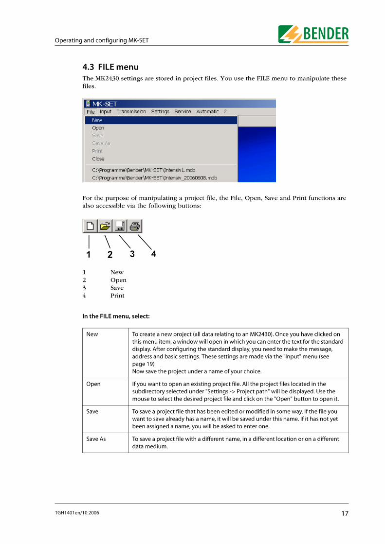
4.3 FILE menuThe MK2430 settings are stored in project files. You use the FILE menu to manipulate these files.
For the purpose of manipulating a project file, the File, Open, Save and Print functions are also accessible via the following buttons:
1 New2 Open3 Save4 Print
In the FILE menu, select:
New To create a new project (all data relating to an MK2430). Once you have clicked on this menu item, a window will open in which you can enter the text for the standard display. After configuring the standard display, you need to make the message, address and basic settings. These settings are made via the "Input" menu (see page 19) Now save the project under a name of your choice.
Open If you want to open an existing project file. All the project files located in the subdirectory selected under "Settings -> Project path" will be displayed. Use the mouse to select the desired project file and click on the "Open" button to open it.
Save To save a project file that has been edited or modified in some way. If the file you want to save already has a name, it will be saved under this name. If it has not yet been assigned a name, you will be asked to enter one.
Save As To save a project file with a different name, in a different location or on a different data medium.
1 2 3 4
17TGH1401en/10.2006

Operating and configuring MK-SET
Print To print out the settings and texts associated with the current project file. You can decide whether you want the basic settings, standard display, individual alarms, alarm addresses or test addresses to be printed out. In order for settings to be printed out, the relevant box must be checked. All the boxes are checked by default.
If you have a number of printers installed and registered under your Windows system, you can decide which printer is to be used for outputting the data.
Close To exit MK-SET. If the current file has changed since you last saved it, before exiting the program, you will be prompted to save the modified project file.
In the first instance, MK-SET will save all the settings to a temporary file. If settingsare changed or added, you will get the message:
However, if you click OK the changes will only be saved in the temporary file. Ifyou want the changes to be saved in the project file itself, you will need to select"File -> Save".
Whenever messages and basic settings are sent to the MK2430, it is always thesettings in the temporary file that are transferred.
18 TGH1401en/10.2006

Operating and configuring MK-SET
4.4 INPUT menu
You use the "Input" menu to make all the settings for an existing project.
4.4.1 Button functions
Buttons for toggling between menusIn the course of programming an MK2430, you may need to switch frequently between the standard display, messages and addresses and the basic settings. To facilitate this, buttons for each of these functions are provided in the menu bar.
1 Basic device settings2 Standard display3 Messages and addresses
If you use the mouse button to hover over a button without clicking on it, a tooltip will appear. By clicking on the buttons you can switch quickly between the various types of setting.
As far as settings relating to the BMS bus are concerned, you will need to knowhow your MEDICS network is set up and also know the associated deviceaddresses. Incorrect settings can result in malfunctions. For general informationabout the BMS bus, please refer to the "BMS bus" instruction leaflet and the"MK2430" manual. A list of device bus addresses can be created and printed out by selecting "Service-> Bus scan".
Always remember to set the language for your message texts before you startprogramming them. This will ensure that any special characters is displayedproperly in the relevant language. You can access a table of the specialcharacters used via the"? -> Help" menu. Simply select "Index -> Special characters".
Save recent settings: MK-SET provides numerous options for programming theMK2430. If you are programming on quite a large scale, we recommend that yousave your settings every so often. This will protect your settings in the event of anoperating system crash. Simply select "Save" from the "File" menu.
1 2 3
19TGH1401en/10.2006
Operating and configuring MK-SET
4.4.2 Basic device settingsBasic settings are stored in the project file. You can define new basic settings or modify an MK2430’s current basic settings. The default settings proposed by MK-SET are the same as those supplied with a brand new MK2430.
How to modify an MK2430’s current basic settings
1. Connect your PC to the MK2430
2. Read out the MK2430 using the selected address: "Transmission -> Read data from device".
3. MK-SET will ask you whether you want to "Save changes in the file?" Click on "Yes" and then enter a name in order to save the project file.
4. Modify the basic settings that have been read out: "Input -> Basic device settings".
5. Click on "Transmission -> Send basic device settings to device" to transfer new basic settings to the device.
If you are creating a new project file, MK-SET will propose some basic settings, which you can modify in accordance with your requirements.
An MK2430’s basic settings are configured under Parameter 1, Parameter 2 and Parameter 3.
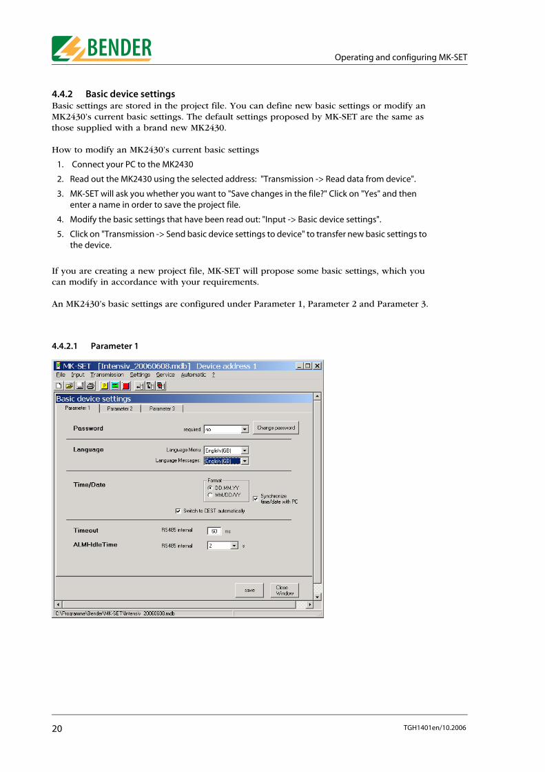
4.4.2.1 Parameter 1
20 TGH1401en/10.2006

Operating and configuring MK-SET
Password Password required:Setting that determines whether a password needs to be entered before changes can be made to the basic settings. Default setting: "No".Settings directly at the MK2430 and settings via PC and interface can be password protected.Change password:Set and confirm a new password. This setting will only be available if the password prompt is"ON". The default MK2430 password is "807".
Language Language menu:Here you can select the language for using the menus.Language messages:Here you can select the language for MK2430 message texts. These standard message texts are available in 20 languages. The associated character set is activated (special characters) for individual message texts.
Time/Date Date format:DD.MM.YY European formatMM/DD/YY US format"Synchronize time/date with PC" box:
The time and date are transferred from the PC.The boxes for entering the time and date appear.
When an MK2430 is read out, the time and date displayed here will be that of the MK2430 on read-out. When the basic settings are sent, the time and date entered/stored in these fields is transferred to the MK2430."Switch to CEST automatically" box:Setting for automatic switchover to Central European summer time.
Automatic switchover.No switchover.
Timeout The factory setting may only be changed in consultation with Bender Service.
ALMI-Idle Time The factory setting may only be changed in consultation with Bender Service.
21TGH1401en/10.2006
Operating and configuring MK-SET
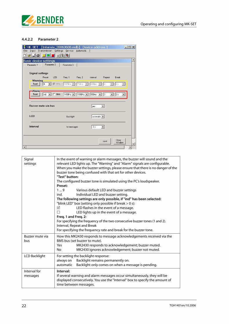
4.4.2.2 Parameter 2
Signal settings
In the event of warning or alarm messages, the buzzer will sound and the relevant LED lights up. The "Warning" and "Alarm" signals are configurable. When you make the buzzer settings, please ensure that there is no danger of the buzzer tone being confused with that set for other devices."Test" button:The configured buzzer tone is simulated using the PC’s loudspeaker.Preset:1 ... 9 Various default LED and buzzer settingsind. Individual LED and buzzer setting. The following settings are only possible, if "ind" has been selected:"blink LED" box (setting only possible if break > 0 s):
LED flashes in the event of a message.LED lights up in the event of a message.
Freq. 1 and Freq. 2:For specifying the frequency of the two consecutive buzzer tones (1 and 2).Interval, Repeat and BreakFor specifying the frequency rate and break for the buzzer tone.
Buzzer mute via bus
How this MK2430 responds to message acknowledgements received via the BMS bus (set buzzer to mute).Yes MK2430 responds to acknowledgement; buzzer muted.No MK2430 ignores acknowledgement; buzzer not muted.
LCD Backlight For setting the backlight response:always on Backlight remains permanently on. automatic Backlight only comes on when a message is pending.
Interval for messages
Interval:If several warning and alarm messages occur simultaneously, they will be displayed consecutively. You use the "Interval" box to specify the amount of time between messages.
22 TGH1401en/10.2006

Operating and configuring MK-SET
4.4.2.3 Parameter 3
Digital inputs (MK2430-11 only)
Neutral alarm messages or messages that relate specifically to medical applications can be assigned to the digital inputs (see the MK2430 manual or MK-SET Help for details). These alarm messages are sent to other MK.... or TM panels via the BMS bus and displayed there in plain text format. If freely programmable alarm messages need to be displayed on a different MK2430 or a TM panel, the same alarm messages must have been programmed in the displaying device."Function" box:neutral The alarm, channel and address of the device that is responsible for
triggering the alarm are all signalled. medical A set function is assigned to each output. Preprogrammed alarm
messages are signalled.
In the event of an alarm, the following is displayed:
Input Function: neutral Function: medicalIN1 Alarm: Address/channel XXX/01 Alarm: OxygenIN2 Alarm: Address/channel XXX/02 Alarm: VacuumIN3 Alarm: Address/channel XXX/03 Alarm: Nitrous oxideIN4 Alarm: Address/channel XXX/04 Alarm: Compressed air 5 barIN5 Alarm: Address/channel XXX/05 Alarm: Compressed air 8 barIN6 Alarm: Address/channel XXX/06 Alarm: NitrogenIN7 Alarm: Address/channel XXX/07 Alarm: CO2
IN8 Alarm: Address/channel XXX/08 Alarm: UPS battery operationIN9 Alarm: Address/channel XXX/09 Alarm: UPS overloadIN10 Alarm: Address/channel XXX/10 Alarm: UPS converter failureIN11 Alarm: Address/channel XXX/11 Alarm: UPS faultIN12 Alarm: Address/channel XXX/12 Alarm: UPS test run
23TGH1401en/10.2006

Operating and configuring MK-SET
Digital inputs (MK2430-11 only)
Channels 1...12: Select "Alarm at 24 V" or "Alarm at 0 V".If an individual alarm has already been programmed for a digital input (channel) (see “Programming individual alarms” on page 29), this will take priority. This channel setting is grey-shaded out and cannot be modified here (in the above example, the setting for channel 5).
Default settings for alarm LEDs:In the case of messages relating to medical gases, the "ALARM" LED lights up; in the case of UPS messages the "WARNING" LED lights up. If the "neutral" function is selected, the "WARNING" LED will light up for all messages. You can modify the settings for each individual channel in the "Individual alarms" window.
Relay(MK2430-11 only)
"Function" box:You can select which events should trigger switching of the alarm relay:Device fault, common error message, device failure or test (Isometer).Operating mode (alarm relay):N/O operation During normal operation relay is deenergized; energized in
the event of an alarm.N/C operation During normal operation, relay is deenergized; energized in
the event of an alarm.
Diagnostic information (for Bender Service)
History memory Displays the number of entries in the history memory (with reset option). The history memory is also cleared whenever message texts are sent to the MK2430.
Reset counter Displays the number of power-down and watchdog resets (with reset option).
24 TGH1401en/10.2006

Operating and configuring MK-SET
4.4.3 Programming the standard displayProgramming of the texts which appears in lines 1..3 of the LC display on the MK2430 during normal (fault-free) operation.
1. First, specify the device address of the MK2430 you wish to program. If you are changing the existing address, enter the new address here.
2. Now enter the text that is to be displayed on the first three lines of the display during normal, fault-free operation.
3. As well as general text, measured values can also be displayed (e.g. insulation resistance, load current). Simply click "Yes" in the relevant "Value" field and then select the address and channel of the device whose measured value is to be displayed.
Example 1: Insulation monitoring device with load and temperature monitoring 107TD47:
Channel Information Note
1 Insulation OK The insulation resistance is higher than the response value. The current insulation resistance is transferred in the form of a measured value.
2 Load current measurement OK
The load current is below the response value. The current utilization rate of the IT system transformer (in relation to the set rated current) is transferred as a percentage.
25TGH1401en/10.2006

Operating and configuring MK-SET
4.4.4 Programming messages and addressesYou use this window to configure individual alarms, alarm addresses and test addresses.
Buttons available in the "Messages and Addresses" windowThe "Messages and Addresses" menu features the following buttons for programming various functions:
If you move the mouse to a button without clicking on it, a tooltip will appear. The buttons have the following functions:
For documentation purposes, an info text (max. length 256 characters) can beentered in a memo field. This will appear when you position the mouse pointeron the free area in the "Standard display" window and right-click. The info textwill continue to be displayed in the status bar (on the left next to the versionnumber) for as long as the "Standard display" window remains open.
An info text can be assigned to the "Messages and Addresses" window in exactlythe same way.The info texts are only saved to the project file. They are not transferred to theMK2430.
New data record Use this button to create a new data record for programming purposes.
Close window Use this button to exit programming for the function called. The settings are applied.
Delete data record Use this button to delete the data record currently on display.
Cutdata record
Use this button to cut the current data record (i.e. copy it to the clipboard and delete it).
26 TGH1401en/10.2006

Operating and configuring MK-SET
4.4.4.1 Programming alarm addressesSetting of bus addresses for devices whose alarm messages are to be displayed as standard texts on the MK2430 that is being programmed.The alarm messages relating to the digital inputs of the MK2430 that is being programmed do not have to be programmed. These alarm messages are always displayed.
1. Press to create a new data record or use or to select an existing data record for editing.
Sortdata records
Use this button to sort all data records that have been programmed thus far for the called function. The main criterion for sorting is the device address.
Copydata record
Use this button to copy the data record currently on display to the clipboard.
Pastedata record
Use this button to paste a data record that has been copied or cut into the current data record.
Scroll through data records
Use these buttons to scroll to the previous or next data record (click and hold the mouse button for rapid scrolling).
Use these buttons to jump to the first or last data record.
27TGH1401en/10.2006

Operating and configuring MK-SET
2. Select the address of the device whose alarm messages are to be displayed. Selected addresses are monitored for presence on the BMS bus; if a device cannot be found on the bus, a corresponding message will appear.
3. All the alarm messages for the selected device will appear on the MK2430’s display. Select the text that you want to appear in the first line of the display. If a number of systems or areas (e.g. several operating theatres) are connected to the MK2430, the numbers 1...4 can be assigned to them. Alternatively, you can enter text in accordance with your requirements.
4. Press to save your settings (temporary file).
To program additional alarm addresses, repeat steps 1...4.
Deleting alarm addressesPress to delete the current data record. If a test address has been programmed for this data record, you will need to delete this address first.
Save recent settingsOnce you have finished programming all the alarm addresses, click on "Close window". If you have made any recent changes, you will be prompted to save them (temporary file). We also recommend that you save the latest version of the project file ("File -> Save").
The settings in the "Individual alarms" window always take priority over those inthe "Alarm addresses" window. If an "individual alarm" has been configured foran address channel, the associated message text will be displayed in its entirety(including blank lines) in the event of an alarm. The settings in the "Alarmaddresses" window will be ignored in respect of this channel.
28 TGH1401en/10.2006

Operating and configuring MK-SET
4.4.4.2 Programming individual alarmsHere you can configure how and where individual alarms (warnings and alarm messages) are to be displayed. Individual alarms can:
● trigger a buzzer message,
● be output to an LED,
● be displayed as message text/additional text on the LC display,
● display measured values, the time and date and/or the alarm address on the LC display.
Creating or selecting a data recordYou can create a new data record in the "Individual alarms" window by pressing the button (indicated by an arrow in the above screenshot) or select the data record you wish to edit using .
Programming a messageA buzzer signal and LED can be assigned to each individual alarm:
Buzzer Setting indicating whether the buzzer should be activated for this warning and alarm message. Select:On Buzzer will sound in the event of this alarmunchanged This alarm will not have any effect on the buzzer. If the buzzer
was silent before the alarm, it will remain silent.
LED Setting indicating whether the "WARNING" or "ALARM" LEDs (or neither of them) should light up in the event of this warning and alarm message.
29TGH1401en/10.2006

Operating and configuring MK-SET
Programming an inputSelect the "Input" connected to the device whose warning and alarm messages are to be displayed. You may select:
Warning and alarm messages received via the BMS bus
Example 1: Insulation monitoring device with load and temperature monitoring 107TD47:
* As far as these messages are concerned, measured values can also be displayed.
buzzer reactivate If an alarm message is triggered, you can use the "Buzzer OFF" key on the MK2430 to deactivate the buzzer. However, just in case you forget about the pending message, the buzzer will sound again once the time specified in the "Buzzer repetition field" has elapsed.
RS-485 internal Internal BMS bus. In the "Device address" field, enter the address of the device whose warning and alarm messages are to be displayed. In the "Channel" field, select the alarm message channel (see "BMS device channel assignment" instruction leaflet).
MK2430 digital inputs
Under "Operating mode", set the operating mode (alarm at 24 V/0 V) and type of signal (pulse/continuous) and under "No." set the number for the digital input. The settings in the "Individual alarms" window take priority over those in the "Basic settings" window (see “Parameter 3” on page 23).
Channel Information Note
0 Device failure 107TD47 failure.
1 Insulation fault* The insulation resistance is lower than the response value.
2 Overcurrent* The load current has exceeded the response value.
3 Overtemperature The transformer temperature has exceeded the response value.
4 Connection fault Test lead wire break.
5 PE connection fault PE wire break
6 Transformer short-circuit
The transformer connection for measuring the current has been short-circuited.
7 Connection fault Transformer connecting cable wire break
8 Operating theatre lights alarm
Insulation fault in the IT system for the operating theatre lights. This message originates from the NC contact of an external insulation monitoring device.
9 Device error Internal 107TD47 error. See documentation relating to the 107TD47.
30 TGH1401en/10.2006
Operating and configuring MK-SET
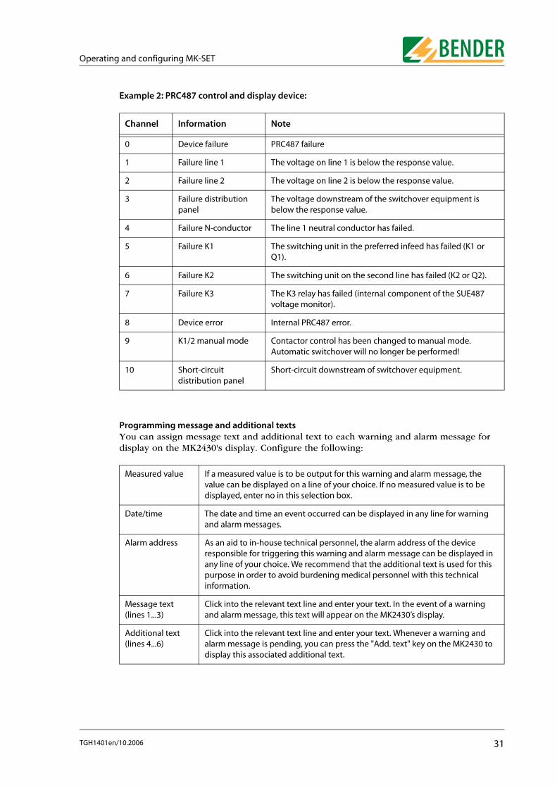
Example 2: PRC487 control and display device:
Programming message and additional textsYou can assign message text and additional text to each warning and alarm message for display on the MK2430's display. Configure the following:
Channel Information Note
0 Device failure PRC487 failure
1 Failure line 1 The voltage on line 1 is below the response value.
2 Failure line 2 The voltage on line 2 is below the response value.
3 Failure distribution panel
The voltage downstream of the switchover equipment is below the response value.
4 Failure N-conductor The line 1 neutral conductor has failed.
5 Failure K1 The switching unit in the preferred infeed has failed (K1 or Q1).
6 Failure K2 The switching unit on the second line has failed (K2 or Q2).
7 Failure K3 The K3 relay has failed (internal component of the SUE487 voltage monitor).
8 Device error Internal PRC487 error.
9 K1/2 manual mode Contactor control has been changed to manual mode. Automatic switchover will no longer be performed!
10 Short-circuit distribution panel
Short-circuit downstream of switchover equipment.
Measured value If a measured value is to be output for this warning and alarm message, the value can be displayed on a line of your choice. If no measured value is to be displayed, enter no in this selection box.
Date/time The date and time an event occurred can be displayed in any line for warning and alarm messages.
Alarm address As an aid to in-house technical personnel, the alarm address of the device responsible for triggering this warning and alarm message can be displayed in any line of your choice. We recommend that the additional text is used for this purpose in order to avoid burdening medical personnel with this technical information.
Message text(lines 1...3)
Click into the relevant text line and enter your text. In the event of a warning and alarm message, this text will appear on the MK2430’s display.
Additional text(lines 4...6)
Click into the relevant text line and enter your text. Whenever a warning and alarm message is pending, you can press the "Add. text" key on the MK2430 to display this associated additional text.
31TGH1401en/10.2006
Operating and configuring MK-SET
Programming more individual alarmsPress to save the settings made thus far (temporary file). To program additional alarm addresses, repeat the steps from "Chapter " onwards.
Deleting individual alarmsPress to delete the current data record. If a test address has been programmed for this data record, you will need to delete this address first.
Save recent settingsOnce you have finished programming all the individual alarms, click on "Close window". If you have made any recent changes, you will be prompted to save them (temporary file). We also recommend that you save the latest version of the project file ("File -> Save").
The settings in the "Individual alarms" window always take priority over those inthe "Alarm addresses" window. If an "individual alarm" has been configured foran address channel, the associated message text will be displayed in its entirety(including blank lines) in the event of an alarm. The settings in the "Alarmaddresses" window will be ignored in respect of this channel.
32 TGH1401en/10.2006

Operating and configuring MK-SET
4.4.4.3 Programming test addressesThis is where you specify the BMS bus addresses of the insulation monitoring devices that are to be tested by pressing the "TEST" button on the MK2430. You can specify up to 30 addresses. The test is carried out sequentially and evaluated automatically.The setting can only be made for devices which have also been activated in the "Alarm addresses" window and/or programmed for individual alarm texts.
Individual alarm texts are a minimum requirement for:
● Channel 1...3 (setting "107TD47")
● Channel 1 (setting "IRDHxxx")
1. Press to create a new data record or use or to select an existing data record for editing.
2. Select the address of the device you want to run the test on.
3. Select the type of insulation monitoring device.
4. Press to save your settings (temporary file).
To program additional test addresses, repeat steps 1...4.
Save recent settingsOnce you have finished programming all the test addresses, click on "Close window". If you have made any recent changes, you will be prompted to save them (temporary file). We also recommend that you save the latest version of the project file ("File -> Save").
33TGH1401en/10.2006

Operating and configuring MK-SET
4.5 TRANSMISSION menuThe "Transmission" menu is used for data transfer between the PC running MK-SET and an MK2430.
ButtonsAs an alternative to the "Transmission" menu, you can also use the following buttons to read out and program the MK2430.
1 Read data from device2 Send basic device settings to device3 Send messages and alarms to device
4.5.1 Read data from deviceMK-SET downloads the settings from an MK2430 that has already been programmed to your PC and displays all the texts and parameters. If required, changes can be entered in MK-SET or the configuration file can be used to program another MK2430 with an identical or similar function.
1. Select "Transmission -> Read data from device".
2. Select the address of the MK2430 whose data you want to read out.
3. Click on the "Receive" button.
Data will now start to be downloaded from the MK2430 to your PC. The progress bar will tell you when transmission is complete.
1 2 3
34 TGH1401en/10.2006
Operating and configuring MK-SET
4.5.2 Send data to device
Data is transferred to the MK2430 in two stages. The basic settings are sent to the MK2430 first. These are then followed by the messages and alarms. It is always the data from the current temporary file that is used for transmission purposes.
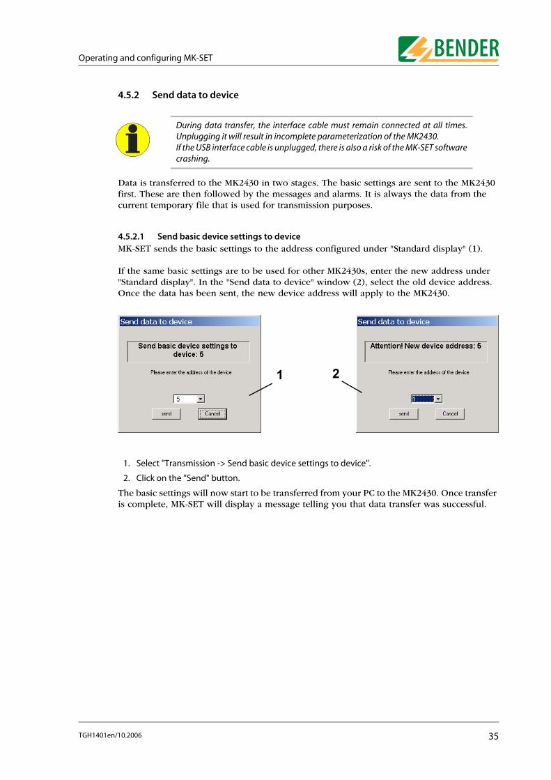
4.5.2.1 Send basic device settings to deviceMK-SET sends the basic settings to the address configured under "Standard display" (1).
If the same basic settings are to be used for other MK2430s, enter the new address under "Standard display". In the "Send data to device" window (2), select the old device address. Once the data has been sent, the new device address will apply to the MK2430.
1. Select "Transmission -> Send basic device settings to device".
2. Click on the "Send" button.
The basic settings will now start to be transferred from your PC to the MK2430. Once transfer is complete, MK-SET will display a message telling you that data transfer was successful.
During data transfer, the interface cable must remain connected at all times.Unplugging it will result in incomplete parameterization of the MK2430. If the USB interface cable is unplugged, there is also a risk of the MK-SET softwarecrashing.
1 2
35TGH1401en/10.2006

Operating and configuring MK-SET
4.5.2.2 Send messages and alarms to device
1. Select "Transmission -> Send messages and alarms to device".
2. Click on the "Send" button.
The data will now start to be transferred from your PC to the MK2430. The progress bar will tell you when transmission is complete.
MK-SET sends the messages (message texts) to the address configured under"Standard display". Whenever you send settings, the messages stored in the MK2430’s historymemory will be deleted, so remember to save any messages that are still requiredbefore you send the settings (e.g. using the MediHistory software).
36 TGH1401en/10.2006

Operating and configuring MK-SET
4.6 SETTINGS menu This menu is used to configure the PC interface, set the language for using the MK-SET menus and select the directory in which project files are to be saved.
PC interface Interface:Select a serial interface ("COM1" ... "COMx") for data transfer with the MK2430.Only if you are using a USB interface: The number of an unassigned COM interface will be allocated to the USB interface. Example: If the computer has a COM1 and COM2 interface, a virtual COM3 interface will be displayed. Select this virtual setting in order to transfer data via a USB interface. Interfaces will only be displayed if they exist and are available (not being used by another program).Baud rate:Please ensure that the baud rate value in MK-SET is identical to that set on the MK2430. Data transfer can only be performed if the two settings match.
Language * Select whether MK-SET is to run in English or German.
Project path Under "Drive" and "Project path", specify where the MK2430 settings are to be stored.
* Please remember to select the required language before carrying out semi-automatic programming. If you switch the language in the middle of semi-automatic programming, your texts will appear in a mixture of German andEnglish.
37TGH1401en/10.2006

Operating and configuring MK-SET
4.7 SERVICE menu
The "Bus scan" function is used to scan the entire MEDICS network. All detected devices are displayed with their device addresses and version numbers. This overview makes the programming process easy. You can also use this function to check that all devices have been connected correctly and their bus addresses have been set correctly.
1. The bus scanning process stops as soon as the system detects a series of unassigned consecutive addresses. If you want to scan the entire BMS bus, select "Scan all Addresses".
2. Click on the "Start" button. Bus scanning will now commence. The progress bar will tell you when the process is complete.
3. At the end of the process, you will be presented with the address, type and firmware version of the devices detected during the scan. Click on the "Print" button if you want to print out the list.
The "Bus scan" function will only be available if there is a connection betweenMK-SET and the BMS bus (RS-485 interface). If the USB interface is being used forthe connection with the MK2430, the function cannot be used.
38 TGH1401en/10.2006
Operating and configuring MK-SET
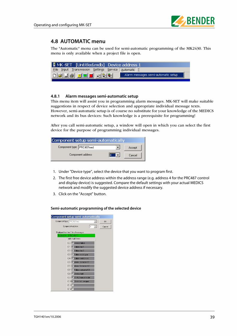
4.8 AUTOMATIC menuThe "Automatic" menu can be used for semi-automatic programming of the MK2430. This menu is only available when a project file is open.
4.8.1 Alarm messages semi-automatic setupThis menu item will assist you in programming alarm messages. MK-SET will make suitable suggestions in respect of device selection and appropriate individual message texts. However, semi-automatic setup is of course no substitute for your knowledge of the MEDICS network and its bus devices: Such knowledge is a prerequisite for programming!
After you call semi-automatic setup, a window will open in which you can select the firstdevice for the purpose of programming individual messages.
1. Under "Device type", select the device that you want to program first.
2. The first free device address within the address range (e.g. address 4 for the PRC487 control and display device) is suggested. Compare the default settings with your actual MEDICS network and modify the suggested device address if necessary.
3. Click on the "Accept" button.
Semi-automatic programming of the selected device
39TGH1401en/10.2006

Operating and configuring MK-SET
Programming alarm messages
1. Enter the message text that you want to be displayed in the first line for all warning and alarm messages.
2. With the mouse, check the boxes for any alarm messages you want to appear on the MK2430’s display.
Confirming your programming settings
● When you have finished making all the necessary settings for this device, click on the "OK" button.
Programming additional devices
● Configure each device on the MEDICS network as described above.
● When you have finished configuring all the devices, click on the "Exit" button.
If you need to carry out any fine-tuning or if you need to program switching commands, select the relevant settings from the "Input" menu.
Saving your settings and transferring them to the MK2430
● Save the project file to your PC (File -> Save).
● Transfer the settings to your MK2430 (Transmission -> Send messages and alarms to device).
4.9 Help menuYou can access the following information via the "?" menu:
Help Online user help
Info Software version
40 TGH1401en/10.2006

Operating and configuring MK-SET
4.10 Example of how to program an MK2430
4.10.1 Essential informationMK-SET makes light work of programming an MK2430 on a MEDICS network. However, in order to carry out programming you will still need a sound knowledge of the MEDICS network and all the network components. You will need to know:
● How the network is structured. Which devices are connected via the internal interface?
● The addresses of all the devices on the network. Addresses have to be assigned uniquely.
● Which messages are to be displayed where? Is there a central MK2430 installed in the central instrumentation and control room which is set up to receive messages from all the devices?
● Is any additional technical equipment included in the system via the digital inputs or interface converter?
4.10.2 ExampleAn intensive care unit with two IT systems is supplied via two switchover and monitoring modules with MEDICS® UFC107E-.. insulation fault location system. As an alternative to the EDS474 insulation fault evaluator, the EDS461 can also be used.
4.10.2.1 Address settings
Device Parameter Address settings
First UFC107E switchover and monitoring module
107TD47 Address 3
PRC487 Address 4
PGH474 Address 111
EDS474-12 Address 61
Second UFC107E switchover and monitoring module
107TD47 Address 5
PRC487 Address 6
PGH474 Address 112
EDS474-12 Address 62
Remote alarm indicator and test combinations
�� �
�� �
�������
�� �
�� �
�������������������������
�������
�������������������������
41TGH1401en/10.2006

Operating and configuring MK-SET
Configure all devices (including the MK2430) with the addresses shown in the table. Each device must have its own unique address.
4.10.2.2 Preliminary steps for connection via BMS busThe four MK2430s can be programmed consecutively via the BMS bus.
1. Connect all the MK2430s to your PC via the BMS bus.
2. Start MK-SET.
3. Call the "Bus scan" function by selecting it in the "Service" menu and print out the result. You will need this list for subsequent programming, so please keep it to hand.
4.10.2.3 Preliminary steps for connection via USB interface
1. Connect the MK2430 that has the address 1 to your PC via a USB interface.
2. Start MK-SET.
You cannot access the "Bus scan" function via a USB interface. Check that the addresses of the individual devices have been set as per the table above.
4.10.2.4 Creating a new project file for the first MK2430
Select "New" from the "File" menu. - This will open a window for programming the standard display.
First MK2430... Address 1
Test address 3, 5
Alarm address 2, 3, 4, 5, 6, 7, 8, 61, 62, 111, 112
Second MK2430...
Address 2
Test address 3, 5
Alarm address 1, 3, 4, 5, 6, 7, 8, 61, 62, 111, 112
Third MK2430...
Address 7
Test address 3, 5
Alarm address 1, 2, 3, 4, 5, 6, 8, 61, 62, 111, 112
Fourth MK2430...
Address 8
Test address 3, 5
Alarm address 1, 2, 3, 4, 5, 6, 7, 61, 62, 111, 112
By default, the language used for menus and message text is set to "German". Ifyou want to use a different language, please remember to set the language formessage texts before you start programming them. This will ensure that anyspecial characters are displayed properly in the relevant language.
Device Parameter Address settings
42 TGH1401en/10.2006
Operating and configuring MK-SET
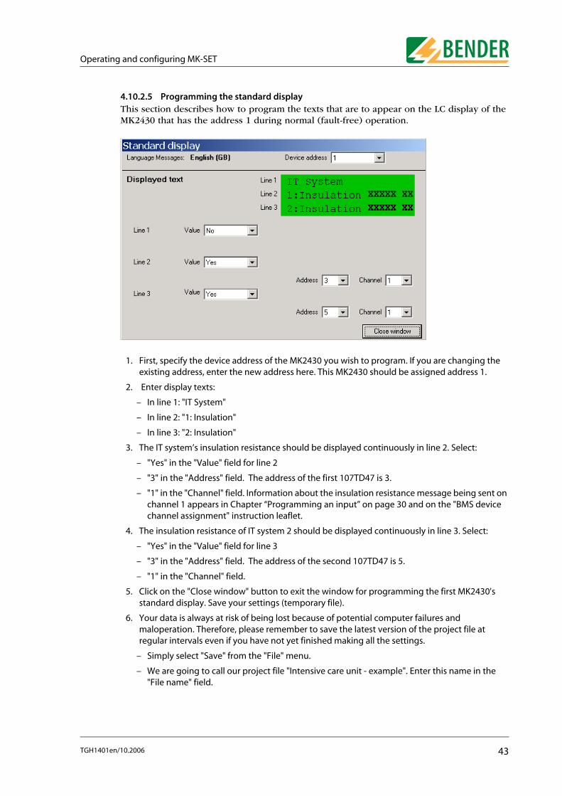
4.10.2.5 Programming the standard displayThis section describes how to program the texts that are to appear on the LC display of the MK2430 that has the address 1 during normal (fault-free) operation.
1. First, specify the device address of the MK2430 you wish to program. If you are changing the existing address, enter the new address here. This MK2430 should be assigned address 1.
2. Enter display texts:
– In line 1: "IT System"
– In line 2: "1: Insulation"
– In line 3: "2: Insulation"
3. The IT system’s insulation resistance should be displayed continuously in line 2. Select:
– "Yes" in the "Value" field for line 2
– "3" in the "Address" field. The address of the first 107TD47 is 3.
– "1" in the "Channel" field. Information about the insulation resistance message being sent on channel 1 appears in Chapter “Programming an input” on page 30 and on the "BMS device channel assignment" instruction leaflet.
4. The insulation resistance of IT system 2 should be displayed continuously in line 3. Select:
– "Yes" in the "Value" field for line 3
– "3" in the "Address" field. The address of the second 107TD47 is 5.
– "1" in the "Channel" field.
5. Click on the "Close window" button to exit the window for programming the first MK2430's standard display. Save your settings (temporary file).
6. Your data is always at risk of being lost because of potential computer failures and maloperation. Therefore, please remember to save the latest version of the project file at regular intervals even if you have not yet finished making all the settings.
– Simply select "Save" from the "File" menu.
– We are going to call our project file "Intensive care unit - example". Enter this name in the "File name" field.
43TGH1401en/10.2006

Operating and configuring MK-SET
4.10.2.6 Programming alarm addressesSetting of bus addresses for devices whose alarm messages are to be displayed as standard texts on the MK2430 that has the address 1.
1. Select to create a new data record.
2. Messages relating to the MK2430 in room 2 are to be displayed on the MK2430 that is being programmed. Select:
– "2" in the "Address" field.
– "free text (99)" in the "System No." field.
– In the "Message text in line 1..." field, enter: "MK2430 in room 2".
– Press to save your settings (temporary file).
3. Messages relating to the first 107TD47 are to be displayed on the MK2430 that is being programmed. Select:
– "3" in the "Address" field.
Within the context of MK2430 programming, the "Alarm addresses" functionensures that the standard message texts are actually displayed on the relevantdevice. For each device, a message text can be entered for the first line (150addresses = 150 texts, each with 20 characters). You can use the "Individual alarms" or "Automatic" functions to generateindividual alarm messages. The MK2430 is capable of storing up to 200individual alarm messages.In our example, we are going to program the messages for the two EDS474’ usingthe "Automatic" function and the messages for all the other devices using the"Alarm addresses" function.
44 TGH1401en/10.2006

Operating and configuring MK-SET
– "free text (99)" in the "System No." field.
– In the "Message text in line 1..." field, enter: "1:Insulation monitoring".
– Press to save your settings (temporary file).
4. Messages relating to the first PRC487 are to be displayed on the MK2430 that is being programmed. Select:
– "4" in the "Address" field.
– "System No." in the "System No." field. 1".
– Press to save your settings (temporary file).
5. Messages relating to the second 107TD47 are to be displayed on the MK2430 that is being programmed. Select:
– "5" in the "Address" field.
– "free text (99)" in the "System No." field.
– In the "Message text in line 1..." field, enter: "2:Insulation monitoring".
– Press to save your settings (temporary file).
6. Messages relating to the second PRC487 are to be displayed on the MK2430 that is being programmed. Select:
– "6" in the "Address" field.
– "System No." in the "System No." field. 2".
– Press to save your settings (temporary file).
7. Messages relating to the MK2430 in room 3 are to be displayed on the MK2430 that is being programmed. Select:
– "7" in the "Address" field.
– "free text (99)" in the "System No." field.
– In the "Message text in line 1..." field, enter: "MK2430 in room 3".
– Press to save your settings (temporary file).
8. Messages relating to the MK2430 in room 4 are to be displayed on the MK2430 that is being programmed. Select:
– "8" in the "Address" field.
– "free text (99)" in the "System No." field.
– In the "Message text in line 1..." field, enter: "MK2430 in room 4".
– Press to save your settings (temporary file).
9. Messages relating to the first PGH474 are to be displayed on the MK2430 that is being programmed. Select:
– "111" in the "Address" field.
– "free text (99)" in the "System No." field.
– In the "Message text in line 1..." field, enter: "1:Insulation test device".
– Press to save your settings (temporary file).
10. Messages relating to the second 107TD47 are to be displayed on the MK2430 that is being programmed. Select:
– "112" in the "Address" field.
– "free text (99)" in the "System No." field.
– In the "Message text in line 1..." field, enter: "2:Insulation test device".
45TGH1401en/10.2006

Operating and configuring MK-SET
– Press to save your settings (temporary file).
11. Click on the "Close window" button to exit the window for programming the first MK2430's alarm addresses.
12. Save the latest programming settings to the project file.
4.10.2.7 Programming test addressesThis is where you specify the BMS bus addresses of the insulation monitoring devices. You should test the addresses by pressing the "TEST" button on the MK2430 that has the address 1.
1. When the test is initiated on this MK2430, a response should be triggered on the 107TD47 insulation monitoring device that has the address 3. Select:
– "3" in the "Address" field.
– "107TD47 (1)" in the "Type of Isometer" field.
2. Select to create this data record.
3. When the test is initiated on this MK2430, a response should be triggered on the 107TD47 insulation monitoring device that has the address 5. Select:
– "5" in the "Address" field.
– "107TD47 (1)" in the "Type of Isometer" field.
4. Select to create this data record.
5. Press to save your settings (temporary file).
46 TGH1401en/10.2006

Operating and configuring MK-SET
4.10.2.8 Alarm messages semi-automatic setupThe individual alarm messages relating to both EDS474-12 insulation fault evaluators are to be displayed on the MK2430 that is being programmed.
1. Select "Alarm messages semi-automatic setup" from the "Automatic" menu.
2. Under "Device type", select EDS474-12 and 61 for the "Device address".
3. Click on the "Accept" button.
You can then use the next window to select the messages that are to be displayed for the EDS474-12.
4. In the "Displayed text line 1 for all messages" window, enter "1:Insulation fault ev.".
5. In the left-hand column select all the alarm messages as shown above.
6. Click on the "OK" button to apply the message texts for the EDS474-12.
7. You configure the message texts for the second EDS474-12 (with address 62) in exactly the same way as you did for the first EDS474-12.
8. Save the latest programming settings to the project file.
47TGH1401en/10.2006

Operating and configuring MK-SET
4.10.2.9 Intermediate checkYou have now finished programming the individual alarm messages for the EDS474-12. You should now check what you have done up to this point. Open the "Input -> Messages and Addresses -> Individual alarms" window and check all the alarm messages one by one.
Use the buttons to scroll through all the alarm messages in sequence. Check all the settings for each alarm message, especially the addresses, channels and alarm texts. You should also ensure that the messages are correctly assigned to the "Warning" or "Alarm" LEDs as appropriate.
You can continue to edit the message text, if required. In our example, we need to replace line 3 "Channel 1" with the room information and information about the "Room1 Cir.1" socket outlet circuit where an insulation fault was located by the EDS474-12.
An information text is stored for the standard display and for each individualalarm. If the message was generated semi-automatically, a text will alreadyexist. Right-click inside the message field.
You will then be able to edit the text or enter a new one.
48 TGH1401en/10.2006
Operating and configuring MK-SET
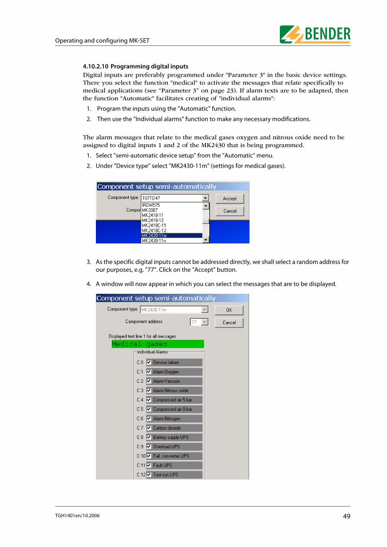
4.10.2.10 Programming digital inputsDigital inputs are preferably programmed under "Parameter 3" in the basic device settings. There you select the function "medical" to activate the messages that relate specifically to medical applications (see “Parameter 3” on page 23). If alarm texts are to be adapted, then the function "Automatic" facilitates creating of "individual alarms":
1. Program the inputs using the "Automatic" function.
2. Then use the "Individual alarms" function to make any necessary modifications.
The alarm messages that relate to the medical gases oxygen and nitrous oxide need to be assigned to digital inputs 1 and 2 of the MK2430 that is being programmed.
1. Select "semi-automatic device setup" from the "Automatic" menu.
2. Under "Device type" select "MK2430-11m" (settings for medical gases).
3. As the specific digital inputs cannot be addressed directly, we shall select a random address for our purposes, e.g. "77". Click on the "Accept" button.
4. A window will now appear in which you can select the messages that are to be displayed.
49TGH1401en/10.2006

Operating and configuring MK-SET
5. In the "Displayed text line 1 for all messages" window, enter "Medical gases".
6. In the left-hand column select both alarm messages as shown above.
7. Click on the "OK" button to apply the message texts. Exit the window for generating message texts semi-automatically.
8. Open the "Input -> Messages and Addresses -> Individual alarms" window. - The two new alarm messages will now be added to the existing ones.
9. Change the "Input" field setting to "Digital input". There is no need to change the channel setting as "1" is already appropriate for our example.
10. Press to save your settings (temporary file).
11. You modify the message text settings for the second digital input in exactly the same way: Change the "Input" field setting to "Digital input". This time you will need to change the channel setting to "2" for the purpose of our example.
12. Press to save your settings (temporary file).
50 TGH1401en/10.2006

Operating and configuring MK-SET
4.10.2.11 Completing the programming processThat is the end of the programming process as far as the first MK2430 in our example is concerned.
1. Now save the project file.
2. Send the data to the MK2430:
– Connect the MK2430 to your PC.
– Select "Send messages and alarms to device" from the "Transmission" menu.
– Click on the "Send" button.
After a few seconds the data transmission is completed. Once it is complete, the MK2430 is fully programmed. Before using it, please check that all the settings are correct. For additional information, please refer to the MK2430 manual.
Now program the three remaining MK2430s in exactly the same way.
51TGH1401en/10.2006

Operating and configuring MK-SET
52 TGH1401en/10.2006

Troubleshooting
5. Troubleshooting
In order to operate correctly, the MK2430 requires a bus system that has been assembled and configured correctly. Please refer to the corresponding documentation.
A list of possible errors and suggestions for rectification appears below. This error list does not claim to be exhaustive.
Error Possible cause
Error transferring the messages or basic settings via the USB interface.
a) Incorrect MK2430 address setting (menu);b) MK2430 address does not match the setting
in the MK-SET configuration software;c) USB cable faulty or not assembled correctly;d) Incorrect PC interface (COM interface) set in
MK-SET;e) USB driver not installed correctly.
Error transferring the messages or basic settings via the BMS bus.
a) Incorrect MK2430 address or baud rate setting (menu);
b) MK2430 address does not match the setting in the MK-SET configuration software;
c) Incorrect setting of address of connected BMS bus devices;
d) Project file created using an incompatible version of MK-SET;
e) Interface cables A/B mixed up;f ) BMS bus terminated incorrectly or not at all;g) Incorrect PC interface set in MK-SET.h) Function not supported by BMS master
firmware version.
The bus scan is not picking up some devices even though the addresses, bus cable and termination are correct.
The device addresses have not been assigned in consecutive order.Addresses have not been assigned uniquely.
Error in respect of function of digital inputs. a) Digital inputs not programmed correctly with MK-SET.
b) Connection fault.
Error transferring data via USB interface (e.g. Read data from device).
The correct sequence has not been observed: "First, connect the MK2430 to the power supply, then connect the USB cable".
Bus scan not working. "Error transferring data to master"
a) Function not supported by BMS master firmware version.
b) PC not connected via RS-485.
53TGH1401en/10.2006

Troubleshooting
54 TGH1401en/10.2006

Programming template
6. Programming template
The MK2430 can be configured in numerous ways. In the interest of maintaining a better overview, we recommend that you make a note of which parameters need to be set before you start programming. Please keep this list so that you have a record of any settings made.
The following programming template can be used for recording your parameters should you wish to make use of BENDER’s programming service, which is available for a fee. Alternatively, you can use the template to help you plan any programming that you intend to undertake yourself on the basis of MK-SET.
55TGH1401en/10.2006

Programming template
he
CompanyStreetZip code/ CityProjectPerson responsibleDateOrder No.Type MK2430....
MK2430 BMS-bus address:
Addresses for device test:
Example: 1 2 3 4 5 6 7 8 9 10 11 12 13 14 15 16 17 18 19 20Standard display Line 1 * * * * S y s t e m i s * * * *(without alarm messages) Line 2 * * R E A D Y T O O P E R A T E *
Line 3 B E N D E R G m b H G r ü n b e r gLine 4 Status line (The content is non-modifiable, it cannot be programmed)
Your specifications: Line 1
Line 2
Line 3Line 4 Status line (The content is non-modifiable, it cannot be programmed)
1 2 3 4 5 6 7 8 9 10 11 12 13 14 15 16 17 18 19 20Example: Line 1 3 I N T E N S I V E C A R E U N I T 3Page 1 Line 2 Alarm text I n s u l a t i o n f a u l t
Line 3 Alarm text M e a s u r e d v a l u w 3 0 k OhmLine 4 Status line 0 1 / 0 3 1 4 : 2 0
Page 2 (additional text) Line 5 3 s i n c e : 2 5 . 0 8 . 0 5 1 6 : 0 8Line 6 Additional text D e v i c e : 1 0 7 T D 4 7Line 7 Additional text A d d r / c h a n n e l 0 0 3 / 0 1Line 8 Status line 0 1 / 0 3 1 4 : 2 0
Alarm address(1...150)
Your specifications: 1234567891011121314151617181920
Parameter setting of MK2430 alarm texts
Enter the alarm addresses to be activated (max. 150) for standard messages and the associated texts to be displayed in the first line of the message. This text specifies the system or equipment assignment (system no., room no. etc.)
The programming of the MK2430 P-version comprises a maximum of 20 alarm addresses to be activated. Ttexts can be grogrammed according to their groups.More alarm addresses can be programmed subject to an additional fee (approx. € 4.- / text message).
1.Line alarm text (group assignment)
Enter the alarm addresses to be activated (max. 150) for standard messages and the associated texts to be displayed in the first line of the message. This text specifies the group assignment (system no., room no. etc.).
56 TGH1401en/10.2006

Programming template
CompanyStreetZip code/CityProjectPerson responsibleDateOrder No.Type MK2430....
InputNeutral alarm messages
Function: "Neutral"Individual alarm messages
Function: "Medical" Your specifications:
IN1 Alarm: Alarm:Address/channel xxx/01 Oxygen
IN2 Alarm: Alarm:Address/channel xxx/02 Vacuum
IN3 Alarm: Alarm:Address/channel xxx/03 Nitrous oxide
IN4 Alarm: Alarm:Address/channel xxx/04 Compressed air 5 bar
IN5 Alarm: Alarm:Address/channel xxx/05 Compressed air 8 bar
IN6 Alarm: Alarm:Address/channel xxx/06 Nitrogen
IN7 Alarm: Alarm:Address/channel xxx/07 CO2
IN8 Alarm: Alarm:Address/channel xxx/08 UPS insulation fault
IN9 Alarm: Alarm:Address/channel xxx/09 UPS overload
IN10 Alarm: Alarm:Address/channel xxx/10 UPS failure converter
IN11 Alarm: Alarm:Address/channel xxx/10 UPS fault
IN12 Alarm: Alarm:Address/channel xxx/11 UPS test run
Select the appropriate function: "Neutral" "Medical"
Add more pages, if required.
Parameter setting of MK2430 digital inputs
Enter the alarm addresses to be activated for standard text messages (max. 150) and their associated texts to be displayed in the first line of the message.This text specifies the group assignment (system no., room no., etc.).
57TGH1401en/10.2006

Programming template
9 209
y
9 20
9 20
sion!
ated. The
).
a certain
it: yy.
CompanyStreetZip code/CityProjectPerson responsibleDateOrder No.Type MK2430....
MK2430 BMS-bus address:
Example:Alarm address range: 1..150) 14
Channel / digital input range: 1..12) 9 1 2 3 4 5 6 7 8 9 10 11 12 13 14 15 16 17 18 1Alarm text Line 1 O P E R A T I N G T H E A T R E 0 2
Line 2 I n s u l a t i o n f a u l tLine 3 S o c k e t F 0 2 8Line 4 Status line (the content is non-modifiable, it cannot be programmed)
Additional text Line 5 D e v i c e : E D S 4 6 1Line 6 A d d r / c h a n n e l 0 1 4 / 0 9Line 7 M e a s . v a l u e : x x x x x yLine 8 Status line (the content is non-modifiable, it cannot be programmed)
Your specifications:
Alarm address (range: 1..150)Channel / digital input (range: 1..12) 1 2 3 4 5 6 7 8 9 10 11 12 13 14 15 16 17 18 1
Alarm text Line 1
Line 2
Line 3Line 4 Status line (the content is non-modifiable, it cannot be programmed)
Additional text Line 5
Line 6
Line 7Line 8 Status line (the content is non-modifiable, it cannot be programmed)
Alarm address (range: 1..150)Channel / digital input(range: 1..12) 1 2 3 4 5 6 7 8 9 10 11 12 13 14 15 16 17 18 1
Alarm text Line 1
Line 2
Line 3Line 4 Status line (the content is non-modifiable, it cannot be programmed)
Additional text Line 5
Line 6
Line 7Line 8 Status line (the content is non-modifiable, it cannot be programmed)
Parameter setting of individual MK2430 alarm texts
The parameter setting of individual alarm texts are subject to an additional fee and is not included in the scope of services of the"P" ver
The programming of the MK2430 P-version comprises a maximum of 20 alarm addresses to be activtexts can be programmed according to their groups.More alarm addresses can be programmed subject to an additional fee (approx. € 4.- / text message
Create individual message texts (max. 200) as illustrated in the example below.If already an alarm address for standard messages has been activated for an alarm message, here you have the possibility to overwrite the message forchannel (individual texts take priority over standard texts)
Individual alarm text
Individual alarm text
If you wish to display measured values, use the columns 13 to 20: Value xxxxx, un
58 TGH1401en/10.2006

Programming template
Your specifications:
Alarm address (range: 1..150)Channel / digital input (range: 1..12) 1 2 3 4 5 6 7 8 9 10 11 12 13 14 15 16 17 18 19 20
Alarm text Line 1
Line 2
Line 3Line 4 Status line (the content is non-modifiable, it cannot be programmed)
Additional text Line 5
Line 6
Line 7Line 8 Status line (the content is non-modifiable, it cannot be programmed)
Individual alarm text
59TGH1401en/10.2006

Programming template
19 20
19 20
19 20
19 20
19 20
Your specifications:
Alarm address (range: 1..150)Channel / digital input (range: 1..12) 1 2 3 4 5 6 7 8 9 10 11 12 13 14 15 16 17 18
Alarm text Line 1
Line 2
Line 3Line 4 Status line (the content is non-modifiable, it cannot be programmed)
Additional text Line 5
Line 6
Line 7Line 8 Status line (the content is non-modifiable, it cannot be programmed)
Add more pages, if required.
Individual alarm text
60 TGH1401en/10.2006

INDEX
Numerics107TD47 operational status
messages 25107TD47 warning and alarm
messages 30
AAdditional text 29, 31Address
- New 25, 43Alarm messages 9Automatic sub-menu 39
BBacklight 22Basic settings 9, 20, 35Blink LED 22BMS bus
- Overview 38Buttons 19, 26, 34
- Tooltip 26Buzzer message 29Buzzer mute 22Buzzer reactivate 30
CCD drive 10, 12Checking settings 48Closing MEDI-SET 18Completing the programming
process 51Configuration software 5
DData transfer 34Date format 21Device address
- New 35Device addresses 19
Display text 43Download area 5
HHelp 40History memory 36
IInput sub-menu 19Installation 10Intended use 7Interface 37Interval 22
LLanguage
- MEDI-SET 37- Menu 21- Messages 21
MManipulating files 17Message text 29, 31
OOperating systems 9Ordering information 9
PPassword prompt 21Personnel 8PRC487 warning and alarm
messages 31Printing settings 18program semi-automatically
39Programming, example 41Project
- Create new 17
Project file 17Project path 37
RRead data from device 34Remote alarm indicator and
operator panels 7
SScan bus 38Scanning of the BMS bus 9Setting the buzzer tone 22Settings sub-menu 37Signal settings 22Software clause 8Software version 40Standard display 9, 25, 43
- Entering text 17Switch to CEST automatically
21Synchronise time /date with PC
21System requirements 9
TTemporary file. 18Test addresses 9Time/Date 21Transmission sub-menu 34
UUpdates 12
WWarning and alarm messages
9
61TGH1401en/10.2006

INDEX
62 TGH1401en/10.2006


Dipl.-Ing. W. Bender GmbH & Co.KGLondorfer Str. 65 • 35305 Grünberg • GermanyPO Box 1161 • 35301 Grünberg • Germany
Tel.: +49 (0)6401-807-0Fax: +49 (0)6401-807-259
E-mail: [email protected] server: http://www.bender-de.com

Channels of BMS devices
BMS slaves make available alarm- and operating messages as measuring values and/or opera-ting states. Over which channel the BMS master can request this data?
107TD47Insulation Monitoring Device with transformer monitoring
Alarm messages:
Operating messages:
EDS470-12, EDS470E-12, EDS470E2-12, EDS473-12, EDS474-12Insulation fault location system
Alarm messages:
Operating messages:
Channel Meaning
1 Insulation resistance below the response value 1, RF < Ran1
2 Load current above response value (indicating in %)
3 Transformer temperature below the response value
4 Connection fault system (Un )
5 Connection fault PE
6 Short circuit CT input
7 Connection fault CT
8 Insulation fault operating theatre lamp, from N.C. contact of an external insulation monitoring device
9 Internal device error
Channel Meaning
1 Current value of insulation resistance RF
2 Current value of load current in %
Channel Meaning
1 Insulation fault with residual current .... on channel 1
2 „ 2
3 „ 3
4 „ 4
5 „ 5
6 „ 6
7 „ 7
8 „ 8
9 „ 9
10 „ 10
11 „ 11
12 „ 12
none
1210002E / 06.03

Channels of BMS devices
IRDH375B/275/575Insulation Monitoring Device
Alarm messages:
Operating messages:
FTC470XDPProtocol converter PROFIBUS DP <===> BMS
Alarm messages:
Channel Meaning
1 Insulation resistance below the response value 1, RF1 < Ran1
2 Insulation resistance below the response value 2, RF2 < Ran2
3 Connection fault system (Un )
4 Connection fault PE
5 Internal device error
6 Standby
7 Starting EDS system in continous operation with 5 minutes pause (IRDH575 only)
8 Starting EDS system for one cycle (IRDH575 only)
9 Starting EDS system in continous operation without pause (IRDH575 only)
Channel Meaning
1 Current value of insulation resistance RF1
2 Current value of insulation resistance RF2
3 Current value of leakage capacitance Ce
Channel Meaning
1 Free programmable alarm message by PROFIBUS DP-Master
2 „
3 „
4 „
5 „
6 „
7 „
8 „
9 „
10 „
11 „
12 „
2 210002E / 06.03

Channels of BMS devices
Operating messages:
FTC470XMBProtocol converter Modbus RTU <===> BMS
Alarm messages:
Operating messages:
Channel Meaning
1 Free programmable operating message by PROFIBUS DP-Master
2 „
3 „
4 „
5 „
6 „
7 „
8 „
9 „
10 „
11 „
12 „
Channel Meaning
1 Free programmable alarm message by Modbus RTU-Master
2 „
3 „
4 „
5 „
6 „
7 „
8 „
9 „
10 „
11 „
12 „
Channel Meaning
1 Free programmable operating message by Modbus RTU-Master
2 „
3 „
4 „
5 „
6 „
7 „
8 „
9 „
10 „
11 „
12 „
3210002E / 06.03

Channels of BMS devices
IMS480Scanning system for LIM2000-1NL
Alarm messages:
Operating messages:
MK2418CRemote indicator and control panel
Alarm messages:
Operating messages:
Channel Meaning
1 Insulation fault in the IT system of channel 1
2 „ channel 2
3 „ channel 3
4 „ channel 4
5 „ channel 5
6 „ channel 6
Channel Meaning
1 None insulation fault in the IT system of channel 1
2 „ channel 2
3 „ channel 3
4 „ channel 4
5 „ channel 5
6 „ channel 6
Channel Meaning
1 Alarm on digital input 1
2 „ 2
3 „ 3
4 „ 4
5 „ 5
6 „ 6
7 „ 7
8 „ 8
None
4 210002E / 06.03

Channels of BMS devices
PGH47xInsulation fault test device
Alarm messages:
Operating messages:
PRC487Control device for switchover modules
Alarm messages:
Operating messages:
Channel Meaning
1 When input IN1 is set: Start of insulation fault location until IN1 is reset
2 When input IN2 is set: Start of insulation fault location for 1 cycle (approx. 5 Minutes)
3 Operation of the device switched down (rejection)
4 Start/stop insulation fault location via push button
5 Internal device error
None
Channel Meaning
1 Failure Line 1
2 Failure Line 2
3 Failure distribution board
4 Failure N conductor Line 1
5 Failure switching element Line 1
6 Failure switching element Line 2
7 Failure contactor relay K3
8 Internal device error
9 Manual mode
10 Short circuit behind the switchover device
Channel Meaning
1 Line 1 ready for operation
2 Line 2 ready for operation
3 Switching element Line 1 is switched on
4 Switching element Line 2 is switched on
5 Automatic mode
6 Manual mode
5210002E / 06.03

Channels of BMS devices
RCMS470-12, RCMS470E-12Residual current evaluator
Alarm messages:
Operating messages:
SMI471-12Converter for digital inputs ==> BMS
Alarm messages:
Channel Meaning
1 Residual-, over-, undercurrent fault with measuring value ... on channel 1
2 „ 2
3 „ 3
4 „ 4
5 „ 5
6 „ 6
7 „ 7
8 „ 8
9 „ 9
10 „ 10
11 „ 11
12 „ 12
Channel Meaning
1 Measuring value: Residual-, over-, undercurrent on channel 1
2 „ 2
3 „ 3
4 „ 4
5 „ 5
6 „ 6
7 „ 7
8 „ 8
9 „ 9
10 „ 10
11 „ 11
12 „ 12
Channel Meaning
1 Alarm on digital input 1
2 „ 2
3 „ 3
4 „ 4
5 „ 5
6 „ 6
7 „ 7
8 „ 8
6 210002E / 06.03

Channels of BMS devices
Operating messages:
SMI472-12Converter, digital inputs ==> BMS
Alarm messages 0...12,Quantity dependend of the preset ratio of alarm messages / operating messages.In the following example the ratio has been set to 12 alarm messages and 0 operating messages:
Operating messages 0...12,Quantity dependend of the preset ratio of alarm messages / operating messages.In the following example the ratio has been set to 0 alarm messages and 12 operating messages:
Channel Meaning
1 Digital input 9 is set
2 „ 10 „
3 „ 11 „
4 „ 12 „
Channel Meaning
1 Alarm on digital input 1
2 „ 2
3 „ 3
4 „ 4
5 „ 5
6 „ 6
7 „ 7
8 „ 8
9 „ 9
10 „ 10
11 „ 11
12 „ 12
Channel Meaning
1 Digital input 1 is set
2 „ 2 „
3 „ 3 „
4 „ 4 „
5 „ 5 „
6 „ 6 „
7 „ 7 „
8 „ 8 „
9 „ 9 „
10 „ 10 „
11 „ 11 „
12 „ 12 „
7210002E / 06.03

Channels of BMS devices
SMO480-12Converter, BMS ==> digital outputs
Alarm messages:
Operating messages:
SMO481-12Converter, BMS ==> digital outputs
Alarm messages:
Operating messages:
None
Channel Meaning
1 Relay 1 has switched (binary 1) or has not switched (binary 0)
2 „ 2 „
3 „ 3 „
4 „ 4 „
5 „ 5 „
6 „ 6 „
7 „ 7 „
8 „ 8 „
9 „ 9 „
10 „ 10 „
11 „ 11 „
12 „ 12 „
None
Channel Meaning
1 Relay 1 has switched (binary 1) or has not switched (binary 0)
2 „ 2 „
3 „ 3 „
4 „ 4 „
5 „ 5 „
6 „ 6 „
7 „ 7 „
8 „ 8 „
9 „ 9 „
10 „ 10 „
11 „ 11 „
12 „ 12 „
8 210002E / 06.03

Channels of BMS devices
SMO482-12Converter, BMS ==> digital outputs
Alarm messages:
Operating messages:
Alarm messages
depending on the device occur when the measured value falls below or exceeds the response value or when status changesto alarm. Alarm messages are provided by BMS devices and are requested by the BMS Master.
Operating messages
are measuring values and/or information which is constantly provided by BMS devices and that are requested from the BMSMaster via the bus. Some BMS devices (EDS47x) do not provide operating messages, they only provide alarm messages.
None
Channel Meaning
1 Relay 1 has switched (binary 1) or has not switched (binary 0)
2 „ 2 „
3 „ 3 „
4 „ 4 „
5 „ 5 „
6 „ 6 „
7 „ 7 „
8 „ 8 „
9 „ 9 „
10 „ 10 „
11 „ 11 „
12 „ 12 „
9210002E / 06.03
Dipl.-Ing. W. Bender GmbH & Co.KG Tel.: +49 (0)6401-807-0 E-Mail: [email protected] Str. 65 • 35305 Grünberg Fax: +49 (0)6401-807-259 Internet: http://www.bender-de.comPostfach 1161 • 35301 Grünberg
Alle Rechte vorbehalten. Nachdruck und Vervielfältigung nur mit Genehmigung des Herausgebers.Technische Änderungen vorbehalten!
All rights reserved.Reprinting and duplicating
only by permission of publisher.Right to technical modifications reserved!
© 2003 BENDER Germany


