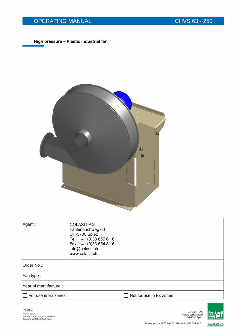
COLASIT AG Plastic construction CH-3700 Spiez Phone +41 (0)33 655 61 61 Fax +41 (0)33 654 81 61 TD-000 680-E Editione 4/2016, Subject of alteration Copyright by COLASIT AG Spiez Page 1 OPERATING MANUAL CHVS 63 - 250 High pressure – Plastic industrial fan Agent : Order No .: Fan type : Year of manufacture : For use in Ex zones Not for use in Ex zones
Transcript
COLASIT AG Plastic construction
CH-3700 Spiez
Phone +41 (0)33 655 61 61 Fax +41 (0)33 654 81 61
TD-000 680-E Editione 4/2016, Subject of alteration Copyright by COLASIT AG Spiez
Page 1
OPERATING MANUAL CHVS 63 - 250
High pressure – Plastic industrial fan
Agent :
Order No .:
Fan type :
Year of manufacture :
For use in Ex zones Not for use in Ex zones
COLASIT AG Plastic construction
CH-3700 Spiez
Phone +41 (0)33 655 61 61 Fax +41 (0)33 654 81 61
TD-000 680-E Editione 4/2016, Subject of alteration Copyright by COLASIT AG Spiez
Page 2
Preface
This operating manual is the driver's license for the operation of this COLASIT fan. It is the main source of information and also the safety guideline. It deserves your full attention - please read it carefully.
The contents of this operating manual are subject to change without notice in order to take technical progress into account. In order to match this operating manual to your COLASIT fan, please register the following particulars of the fan below, whereby reference should be made to the manufacturer’s nameplate.
Whilst reading this manual, you will be guided by symbols which indicate dangers and especially important references.
Very important reference
Generally valid danger warnings which concern your personal safety
Reference to electrical dangers
Reference to dangers resulting from the process environment
The entire operating manual consists of 3 parts
Part 1: General
Part 2: Components
Part 3: Certification
COLASIT AG Plastic construction
CH-3700 Spiez
Phone +41 (0)33 655 61 61 Fax +41 (0)33 654 81 61
TD-000 680-E Editione 4/2016, Subject of alteration Copyright by COLASIT AG Spiez
Page 3
Table of contents Part 1: General ........................................................................................................................................................... 4 1 General ................................................................................................................................................................ 4
1.1 Definition ........................................................................................................................................................ 4 1.2 Manufacture of COLASIT fans ...................................................................................................................... 4 1.3 Warranty ........................................................................................................................................................ 4 1.4 Safety review ................................................................................................................................................. 5 1.5 Qualification of personnel .............................................................................................................................. 5 1.6 Possible emergencies.................................................................................................................................... 5 1.7 The safety inspector (So) .............................................................................................................................. 5 1.8 General risk matrix ......................................................................................................................................... 6 1.9 EU conformity of the COLASIT fan ................................................................................................................ 7 1.10 Restrictions when commissioning ................................................................................................................. 7 1.11 General operating conditons ......................................................................................................................... 7
2 Explosion protection ............................................................................................................................................ 8 2.1 Fan EX marking ............................................................................................................................................. 9 2.2 Correct installation of ATEX fan .................................................................................................................... 9
8 Spare parts ........................................................................................................................................................ 14 9 Operating instructions ....................................................................................................................................... 14 10 Log-book ....................................................................................................................................................... 14 11 Disposal ........................................................................................................................................................ 14 12 Faults and fault clearance ............................................................................................................................. 15 13 Retrofittable original accessories .................................................................................................................. 16 14 Fan identification ........................................................................................................................................... 16 Part 2: Components .................................................................................................................................................. 16 15 Design and function CHVS ........................................................................................................................... 16 16 Dimension ..................................................................................................................................................... 17
16.1 Dimension of the CHVS with direct drive..................................................................................................... 17 16.2 Dimension of the CHVS with V-belt drive .................................................................................................... 18
17 Assembly instructions ................................................................................................................................... 19 17.1 Assembly instructions for CHVS with direct drive ....................................................................................... 19 17.2 Assembly instructions for CHVS with V-belt drive ....................................................................................... 20
18 Spare parts list .............................................................................................................................................. 21 18.1 Spare parts list for CHVS with direct drive .................................................................................................. 21 18.2 Spare parts list for CHVS with V-belt drive .................................................................................................. 22
Part 3: Certification ................................................................................................................................................... 23 19 Certification ................................................................................................................................................... 23
19.1 EU Declaration of Conformity ...................................................................................................................... 23 19.2 ATEX Declaration of Conformity .................................................................................................................. 24 19.3 Other certificates .......................................................................................................................................... 26
20 Form fort he correct assembly of ATEX fans ................................................................................................ 27
COLASIT AG Plastic construction
CH-3700 Spiez
Phone +41 (0)33 655 61 61 Fax +41 (0)33 654 81 61
TD-000 680-E Editione 4/2016, Subject of alteration Copyright by COLASIT AG Spiez
Page 4
Part 1: General
1 General
OBLIGATIONS Prior to any work done on or with the fan, we put you under an obligation to read this operating manual and any further contractors’ operating instructions carefully and through to the end. Should anything not be clear, please get in touch with us immediately. Do not put the fan into operation as long as uncertainties exist. With the commissioning of the fan you confirm that you have read and understood the operating manual.
After having become acquainted with the fan and its operational performance together with your production process, we recommend that you make a note of the different modes of operation in a “process instructions” document.
Together with this operating manual, any acceptance documents such as ATEX, works acceptance certificates and the EU declaration of conformity, the process instructions document forms part of the complete system documentation. For the fan, a separate risk analysis was made as a prerequisite for writing this operating manual. Risks were evaluated and any remaining residual risks are pointed out in this operating manual.
When extracting aggressive gases, it is imperative to review the suitability of the materials: ▪ Once the principal or the operator has notified us of the gas mix and the
maximum operating temperature, the suitability and any applicable restrictions will be confirmed in the data sheet of COLASIT AG.
▪ In the absence of a written notification with regard to the extracted
medium by the principal, the operator is responsible without limitation for assessing the suitability for the operation of the ventilator.
1.1 Definition
The term "COLASIT fan" stands for a Swiss high-quality product and contains all those components and individual parts, as compiled in the purchase order or in the material parts list respectively, which, when assembled, form a functional unit.
1.2 Manufacture of COLASIT fans
The fan was manufactured using to modern manufacturing methods and was extensively tested both during manufacture and as a finished product by the COLASIT quality assurance system. The methods and procedures used for manufacture and production monitoring correspond to the state of the art. The personnel entrusted with the manufacture of the fan have the appropriate skills and possess valid qualifications. All fans complete a successful test run in the manufacturer’s facilities.
1.3 Warranty The warranty ends on the date stated in the general terms of sale and delivery. Warranty is limited to the delivery of spare parts or the repair of defective parts in the manufacturer’s works. Any further claims or the replacement of expendable items or of items subject to normal wear and tear are excluded. We guarantee the availability of spare parts identical in construction to the original over a period of 10 years effective from the date of delivery.
COLASIT AG Plastic construction
CH-3700 Spiez
Phone +41 (0)33 655 61 61 Fax +41 (0)33 654 81 61
TD-000 680-E Editione 4/2016, Subject of alteration Copyright by COLASIT AG Spiez
Page 5
COLASIT only guarantees the stability of materials under the condition that technological data was available before production. Any change in the conditions of use is only permissible after approval by COLASIT; otherwise this entails the loss of warranty. Any changes or repair work during the warranty period may only be made by our fitters or with our written consent.
We refer to the limitation of warranty noted in the “drive“section in the case where a frequency converter supplied by a third party is used.
The fan must be deployed and used in accordance with the conditions mentioned in this operating manual. Only in this way can its function be guaranteed and dangers for persons and material be excluded during operation. We accept no responsibility or guarantee claims for damages arising from non-observance of this manual or from inappropriate operation.
1.4 Safety review After having installed the fan, we recommend checking out the entire operating situation by means of a risk analysis. In this way it can be guaranteed that neither the fan suffers damage nor that the fan causes any damage.
1.5 Qualification of personnel The fan must only be put into operation, handled, operated, maintained and cleaned by trained personnel who are authorised (and competent) to carry out such work. The personnel must possess the appropriate skills needed to operate the fan and be familiar with the effects of the reactions caused by the fan. The personnel qualified for the operation of the fan must be able to react adequately and correctly in the case of a fault or an emergency.
1.6 Possible emergencies An emergency results from the bursting or melting of plastic components as a result of mechanical damage or chemical and thermal influences. In this case, parts may fly off and vapours may be produced which could be hot, corrosive, poisonous, irritating or inflammable. (e.g. hydrochloric acid vapour if PVC gets burnt). A danger of fire exists under certain conditions. For the choice of the correct fire-extinguishing devices and the positioning of the fire-fighting equipment, please follow the recommendations of your official fire-prevention agency.
1.7 The safety inspector (So) The function of the safety inspector or his representative is defined in the operating company’s organisational chart. The name of the person must be known to all personnel who are responsible for the fan. The operating company defines his competencies and his area of responsibility. The safety inspector approves the fan for operation.
COLASIT AG Plastic construction
CH-3700 Spiez
Phone +41 (0)33 655 61 61 Fax +41 (0)33 654 81 61
TD-000 680-E Editione 4/2016, Subject of alteration Copyright by COLASIT AG Spiez
Page 6
1.8 General risk matrix
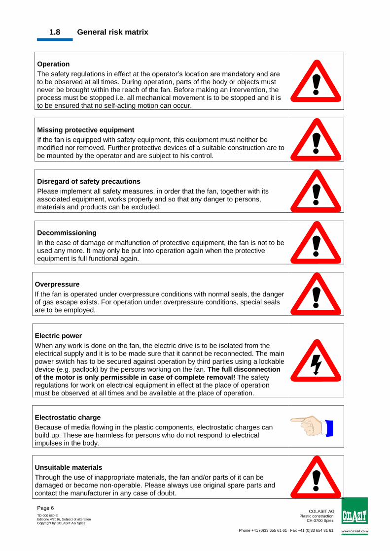
Operation
The safety regulations in effect at the operator’s location are mandatory and are to be observed at all times. During operation, parts of the body or objects must never be brought within the reach of the fan. Before making an intervention, the process must be stopped i.e. all mechanical movement is to be stopped and it is to be ensured that no self-acting motion can occur.
Missing protective equipment
If the fan is equipped with safety equipment, this equipment must neither be modified nor removed. Further protective devices of a suitable construction are to be mounted by the operator and are subject to his control.
Disregard of safety precautions
Please implement all safety measures, in order that the fan, together with its associated equipment, works properly and so that any danger to persons, materials and products can be excluded.
Decommissioning
In the case of damage or malfunction of protective equipment, the fan is not to be used any more. It may only be put into operation again when the protective equipment is full functional again.
Overpressure
If the fan is operated under overpressure conditions with normal seals, the danger of gas escape exists. For operation under overpressure conditions, special seals are to be employed.
Electric power
When any work is done on the fan, the electric drive is to be isolated from the electrical supply and it is to be made sure that it cannot be reconnected. The main power switch has to be secured against operation by third parties using a lockable device (e.g. padlock) by the persons working on the fan. The full disconnection of the motor is only permissible in case of complete removal! The safety regulations for work on electrical equipment in effect at the place of operation must be observed at all times and be available at the place of operation.
Electrostatic charge
Because of media flowing in the plastic components, electrostatic charges can build up. These are harmless for persons who do not respond to electrical impulses in the body.
Unsuitable materials
Through the use of inappropriate materials, the fan and/or parts of it can be damaged or become non-operable. Please always use original spare parts and contact the manufacturer in any case of doubt.
COLASIT AG Plastic construction
CH-3700 Spiez
Phone +41 (0)33 655 61 61 Fax +41 (0)33 654 81 61
TD-000 680-E Editione 4/2016, Subject of alteration Copyright by COLASIT AG Spiez
Page 7
Dangerous media
Depending on the mode of operation, fan parts are in contact with dangerous media. Work on the fan or the carrying out of maintenance work is not allowed during operation. Before carrying out any work, the system has to be freed from any dangerous media and, when required, to be neutralised and secured in such a way that an inflow of dangerous media is prevented.
1.9 EU conformity of the COLASIT fan The fan was designed, built and tested to Directive 2006/42/EC. In addition to this EU Directive and EN standards which have the equivalent status of a Swiss standard, Swiss safety and accident-prevention regulations have also been taken into account. An EU Declaration of Conformity in terms of the EU guidelines 2006/42/EC on machines will be issued along with the fan.
1.10 Restrictions when commissioning
We stipulate that putting into operation is prohibited as long as the fan, including all parts belonging to it or equipment connected to it, has not been installed and checked out and until the operating manual has been read completely before commissioning.
We stipulate that the fan may only be put into operation when the safety inspector has given his approval. He is obliged to record this approval in a protocol.
The disregard of these stipulations constitutes negligence.
1.11 General operating conditons
The permissible operating conditions are indicated on the manufacturer‘s plate.
The fan is not suitable for the transport of solids in the air flow. This operating mode will lead to the destruction of the fan.
The ducts on the intake and delivery sides must always be open. A closed duct will lead to a rise in temperature which could cause the destruction of the fan.
The minimum air speed through the fan is 5 meters per second.
The maximum air speed may not exceed 30 meters per second through the fan.
The standard motors are designed for normal operating conditions (ambient temperature. +40°C, location under 1000 m above sea level, air pressure up to 1050 hPa). In the case of divergence from these conditions, please contact COLASIT.
Compliance with these operating conditions is the responsibility of the operator.
COLASIT AG Plastic construction
CH-3700 Spiez
Phone +41 (0)33 655 61 61 Fax +41 (0)33 654 81 61
TD-000 680-E Editione 4/2016, Subject of alteration Copyright by COLASIT AG Spiez
Page 8
2 Explosion protection
COLASIT plastic fans are suitable for the conveyance of gases in Zone 1 or 2 (Equipment Category 2 or 3) depending on the model. COLASIT plastic fans are not suitable for the conveyance of gases in Zone 0 (Equipment Category 1). The zone classification of the conveyed medium and the site of installation must be made known by the fan operator so that COLASIT can take the necessary measures to prevent the risk of ignition.
The explosion-proof COLASIT fans are not suitable for the conveyance of explosive dusts.
No modifications may be made to ATEX-certified fans. All work on the fan may only be carried out by ATEX-trained skilled personnel. Otherwise the ATEX Certificate will lose its validity.
On ATEX certified fans, the external grounding terminal of the motor and fan must be connected to a potential equalization system.
Motors with protection type "e" are standard for using in the explosion-proof design of our fans. The standard version of the motors used complies with temperature class T3 (maximum surface temperature 200ºC). As special-purpose design, motors with protection type "d" or motors with temperature class T4 (maximum surface temperature 135°C) are also available.
The user must define a suitable temperature class for his application that does not reach the ignition temperature of his conveyed medium.
Please also observe the specifications in the operating instructions of the motor manufacturer. The thermal motor protection must be connected in compliance with the manufacturer's specifications (operating instructions).
If a frequency converter is fitted, we recommend using pressure-proof enclosed motors. In addition, a certified PTC resistor releasing device must be fitted. The following specifications must be included on the motor rating plate: min and max frequencies, min and max speeds, min and max torque or output, limit temperature PTC and PTC release time.
COLASIT AG Plastic construction
CH-3700 Spiez
Phone +41 (0)33 655 61 61 Fax +41 (0)33 654 81 61
TD-000 680-E Editione 4/2016, Subject of alteration Copyright by COLASIT AG Spiez
Page 9
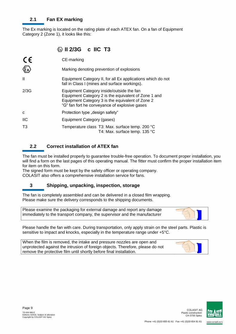
2.1 Fan EX marking The Ex marking is located on the rating plate of each ATEX fan. On a fan of Equipment Category 2 (Zone 1), it looks like this:
II 2/3G c IIC T3 CE-marking Marking denoting prevention of explosions II Equipment Category II, for all Ex applications which do not
fall in Class I (mines and surface workings).
2/3G Equipment Category inside/outside the fan Equipment Category 2 is the equivalent of Zone 1 and Equipment Category 3 is the equivalent of Zone 2 “G“ fan fort he conveyance of explosive gases
c Protection type „design safety“
IIC Equipment Category (gases)
T3 Temperature class T3: Max. surface temp. 200 °C T4: Max. surface temp. 135 °C
2.2 Correct installation of ATEX fan The fan must be installed properly to guarantee trouble-free operation. To document proper installation, you will find a form on the last pages of this operating manual. The fitter must confirm the proper installation item for item on this form. The signed form must be kept by the safety officer or operating company. COLASIT also offers a comprehensive installation service for fans.
3 Shipping, unpacking, inspection, storage
The fan is completely assembled and can be delivered in a closed film wrapping. Please make sure the delivery corresponds to the shipping documents.
Please examine the packaging for external damage and report any damage immediately to the transport company, the supervisor and the manufacturer
Please handle the fan with care. During transportation, only apply strain on the steel parts. Plastic is sensitive to impact and knocks, especially in the temperature range under +5°C.
When the film is removed, the intake and pressure nozzles are open and unprotected against the intrusion of foreign objects. Therefore, please do not remove the protective film until shortly before final installation.
COLASIT AG Plastic construction
CH-3700 Spiez
Phone +41 (0)33 655 61 61 Fax +41 (0)33 654 81 61
TD-000 680-E Editione 4/2016, Subject of alteration Copyright by COLASIT AG Spiez
Page 10
Storage If the fans are not put into operation immediately, store them in a clean dry place where they are protected from impacts, vibrations, and temperature fluctuations and where the air humidity is under 90%. If these storage conditions are not available, switch the fans on at regular intervals to exclude the risk of condensate forming. Before switching on, unscrew the condensate drain plugs each time and replace them afterwards.
Store the fan in a dry, weather-protected place and cover with a tarpaulin to protect it from dust and soiling. If stored for over one year, test whether the fan bearings rotate freely before putting into operation.
4 Installation, design
Before installation, check whether all the locking screws (including the motor screws) are tightened properly. Check the electrical connections if wired at the factory.
Before installation, check that there are no foreign bodies in the coil or in the intake and pressure connections.
The fan must be installed at a location provided and prepared by the customer and must be secured and connected in such a way that any possible vibration occurring can be absorbed by the vibration dampers supplied by COLASIT. If no ducting is foreseen on the intake side, the intake connection should be protected by a sturdy protective grating (10mm mesh) to be provided by the customer. Connection ducting on the pressure side must be routed to prevent the backflow of foreign bodies, rainwater or condensate into the fan. To ensure this, please use the COLASIT condensate drain nozzles. Due to the possibility of noise nuisance, we recommend that the fan should not be installed in the immediate vicinity of workplaces.
The fans of category 2 (zone 1) must be grounded.
5 Commissioning, initial start up, test run
The fan should only be put into operation after inspection and approval by the safety inspector has taken place.
5.1 Inspection of the installation and settings Check list: Prior to commissioning and initial start-up, it must be guaranteed that..
the fan is installed vibration-free and mechanically secured,
all components are cleaned both on the inside and the outside and are free from foreign bodies,
all intake and delivery ducts are connected in a leak-proof and elastic manner,
all rotating parts are protected against unintentional contact,
the electrical connections are installed and their function tested,
a lockable main control switch is available to which the fan is connected,
the EMERGENCY-STOP equipment is functionally tested,
the safety inspector has made sure that safety equipment exists,
COLASIT AG Plastic construction
CH-3700 Spiez
Phone +41 (0)33 655 61 61 Fax +41 (0)33 654 81 61
TD-000 680-E Editione 4/2016, Subject of alteration Copyright by COLASIT AG Spiez
Page 11
the operating personnel is familiar with the operating manual,
the safety inspector has given his approval for the operation of the installation and that no external persons are present in the plant area
If envisaged by procedural regulations provided by the operator, minutes have to be taken on the commissioning work, including the observance of the check list.
5.2 Drive The fan is driven by an electrical motor which is connected either directly or via a v-belt to the impeller shaft. Data on the electrical connection of the motor are indicated on the motor’s data plate or in the motor manufacturer’s data sheet. When speed is controlled by means of a frequency converter, the maximum rotational speed is limited by COLASIT to the value indicated on the manufacturer’s plate.
If the frequency converter is not provided by COLASIT, the operator is responsible for the observance of the maximum rotational speed limit. In this case, COLASIT does not assume any liability for damage that can be attributed to exceeding the maximum rotational speed.
5.3 Electrical installations, EMERGENCY - STOP
The electrical installations may only be carried out by an authorised electrician in accordance with the regulations valid at the site at which the fan is installed.
For the interruption of the power supply, an EMERGENCY-STOP switch is to be provided. It is advisable that this switch be mounted in the vicinity of the emergency exit.
Please request confirmation from the in-house electrician that the electrical installations were carried out and tested in accordance with regulations, that all functions have been tested (or simulated) and that the rotational direction is correct.
Caution
Do not turn power on or off without prior warning to persons in the area where the fan is operating. Switching operations must be co-ordinated with other functions in the working area of the fan.
6 Operation
6.1 Safety regulations
The fan is to be operated according to this manual. In doing so, you will avoid possible damage.
Supervision
The fan must not be operated unattended as long as it conveys substances, whose reactions are unknown or if unexpected reactions are to be anticipated. If the supervision has to be withdrawn for operational reasons, this has to be reported to the safety inspector and the plant has to be secured in such a way that no unauthorised manipulation can be carried out. The safety inspector decides on questions regarding supervision.
COLASIT AG Plastic construction
CH-3700 Spiez
Phone +41 (0)33 655 61 61 Fax +41 (0)33 654 81 61
TD-000 680-E Editione 4/2016, Subject of alteration Copyright by COLASIT AG Spiez
Page 12
6.2 Decomissioning
An internal procedure instruction regulates the work to be carried out as well as the preparatory work for re-commissioning (e.g. cleaning).
7 Maintenance, repair, cleaning
7.1 Preparation
Before any work is carried out on the fan, it has to be brought into its "safety position".
The "safety position" is defined as follows: - Drive is de-energised, the main control switch is secured against switching on, - The fan impeller can be manually rotated, - Fan flushed with fresh air and condensate-free, - Fan is at room temperature, - Personal protective equipment is available and its use is ordered. (Use of protective gloves because of sharp edges, ear protectors if necessary). - A sign, e.g. “in revision", is to be attached to the plant, - The safety devices may be removed, - The work to be carried out must not be done under time pressure, - The general and specific regulations on accident prevention as well as the EKAS guidelines (Switzerland) are to be observed, - The safety inspector is informed about the nature and the course of the works. If the intake and delivery ducts of the fan are dismounted for a longer period of time, the openings are to be closed off.
COLASIT AG Plastic construction
CH-3700 Spiez
Phone +41 (0)33 655 61 61 Fax +41 (0)33 654 81 61
TD-000 680-E Editione 4/2016, Subject of alteration Copyright by COLASIT AG Spiez
Page 13
7.2 Performance
The fan must be maintained in accordance with the Maintenance Plan below. The maintenance work carried out must be noted down in the logbook (see the section on Logbook).
Every week Every month Every year
Make a visual inspection of fan for damage, leaks, corrosion and attachment.
Check the smooth running of the fan and electric motor.
Check state and tension of the V-belt and replace if necessary.
Check the impeller and casing for deposits and clean if necessary.
Check the shaft bearing for smooth running and vibrations. Bearing maintenance.
Remove any dust deposits on the fan and motor.
Check the flexible transitions from fan to duct system for leaks and state.
Check the function of the condensate nozzle.
Check the state of the vibration dampers.
Check the state of the hub gasket (if fitted).
Carry out a thorough cleaning of the entire fan (including impeller).
Check the parts in contact with the conveyed medium for corrosion.
Check the minimum clearance between the impeller and casing (minimum 1% of intake diameter, maximum 20mm).
Measure the vibrations at bearings (KA) or motor (DA). Alarm according to ISO 14694: ≤ 3.7 kW, categorie BV-2: 14.0 mm/s (r.m.s.) or ≤ 300 kW, categorie BV-3: 11.8 mm/s (r.m.s.).
Check the safety devices (e.g. splinter protection or intake grating) for condition and function.
Check the stands for damage and stability.
Check all screw unions for firm seating.
Normally the bearings are designed for a service life of 40,000 hrs. After this period the bearings must be replaced. The service life of the bearings is reduced when subjected to increased requirements (e.g. high temperature, aggressive ambient air or operation with frequency converter).
On drives with V-belts, check the tension regularly and monitor the belts closely particularly during the first weeks of operation. This also applies after long periods of downtime. Excessive tension leads to bearing damage, insufficient tension leads to slip, wear and frictional heat.
After replacing a V-belt, check the tension after 1 to 4 hours of operation and retension as necessary.
Components which are not intended for repair by the operator must be sent to the manufacturer or agent for repair or replacement (e.g. damaged impeller).
Your agent or COLASIT also offers customer services
TD-000 680-E Editione 4/2016, Subject of alteration Copyright by COLASIT AG Spiez
Page 14
Deposits on the impeller and soiling lead to imbalance and as a result to vibrations with undesirable side effects. If vibration occurs, switch the fan off immediately.
Contamination and encrustations should be removed with a soft tool without damaging the surface (e.g. with a wooden spatula or scraper).If possible, use water and a household cleaning agent.
Solvents can corrode the material. These may only be used with the written consent of COLASIT.
To carry out cleaning work, we recommend the production of a process instruction.
8 Spare parts
Please identify components by means of the item and drawing numbers as well as the order number and model designation. Use only original spare parts. Our warranty is void if other or unapproved components are used. Please address your spare parts order to our customer service department
9 Operating instructions
For the operation of the fan, we recommend the preparation of process instructions documentation. Such documents simplify repetitive workflows, reduce the risk of incorrect operation and are a valuable aid when personnel changes occur and for training. If the fan must be qualified, process instruction documents are required. You will find important notes on the preparation of process instructions in various chapters of the operating manual.
To help ensure the safe operation of the fan, COLASIT offers, as a service, the review of process instruction documents prepared by the operator.
10 Log-book
For your own safety and as a contribution to personal responsibility, we recommend the keeping of a log book for the entire operation in which the fan is in use. All events should be registered in the log book. In the case of damage and also in the case of an accident, this document is the first source of information. Please register the following together with, for example, date and signature: - beginning and end of a work cycle - special occurrences, even it these do not concern the fan itself (e.g. power failure, alarm) - change of persons responsible for monitoring (e.g. in the case of shift operation) - repairs carried out and spare parts installed - decommissioning - special instructions - etc.
11 Disposal Before disposing of plastics and other components, (complete or as broken parts), please clean them as necessary to preclude any danger to the environment. Dispose of the components correctly. Instruct a waste-management company to do this or return them to us for disposal.
COLASIT AG Plastic construction
CH-3700 Spiez
Phone +41 (0)33 655 61 61 Fax +41 (0)33 654 81 61
TD-000 680-E Editione 4/2016, Subject of alteration Copyright by COLASIT AG Spiez
Page 15
12 Faults and fault clearance If faults occur, we recommend that you identify and clear them using the following table. If the fault cannot be cleared, please contact our customer service.
Operational fault Possible causes Remedy
Fan runs irregularly
Impeller is unbalanced Re-balancing by a specialised company
Impeller caked up Clean carefully, re-balance if necessary
Material corrosion on impeller caused by conveying aggressive media
Consult the manufacturer
Deformation of impeller because temperature too high
Consult the manufacturer Install a new impeller Check bearings
V-belt drive is not correctly lined up
Adjust belt drive
Drive belt torn or damaged Normal wear and tear
Exchange complete sets of drive belts
Drive belt is too strongly tensioned
Adjust belt drive
Drive belts slip Wrong degree of tensioning
Check belt tension and re-tension if necessary
Foreign objects or dirt in the grooves or the pulleys
Clean the pulleys and check drive belt profile
Leakage on the shaft bushing Seal is not suitable for the mode of operation
Consult the manufacturer
Leakage on the sleeves Sleeves are defective Replace sleeves
Tensioning straps are not firmly tightened
Tighten tensioning straps
Fan output too low
Wrong rotational direction of the impeller
Change direction of rotation
Pressure loss in ducting too high
Different duct configuration
Flow dampers are not or only partially opened
Check opening positions on the spot
Inlet or delivery duct blocked
Remove obstacles
Fan does not reach its rated speed
Electrical control mechanisms are wrongly adjusted
Check adjustment of the motor protective device and if necessary re-adjust
Motor winding is defective Please consult manufacturer
Drive motor is not correctly dimensioned
Please consult manufacturer for the purpose of checking starting torque
Grating noises during operation of the fan or when it runs down
Inlet duct is installed in a distorted way
Remove inlet duct and re-mount it
Temperature rise of the roller bearings
Bearing was not lubricated Change bearing and lubricate regularly according to maintenance instructions
COLASIT AG Plastic construction
CH-3700 Spiez
Phone +41 (0)33 655 61 61 Fax +41 (0)33 654 81 61
TD-000 680-E Editione 4/2016, Subject of alteration Copyright by COLASIT AG Spiez
Page 16
13 Retrofittable original accessories If not already a part of our delivery, these original parts are available ex-stock for further ordering. - Frequency converters - Elastic sleeves - Vibration dampers - Condensate drains - Engine cover for outdoor installations - Splinter protection - Wall console
14 Fan identification
The following rating plate is affixed to each COLASIT fan:
1 Manufacturer
2 Field for CE marking and applicable standards
3 ATEX-identification, for details see the section on Explosion Protection
4 Fan specifications: fan type, casing design, material of casing and impeller, order number and date of manufacture.
5 Technical specifications
Part 2: Components
15 Design and function CHVS All impellers of this series are balanced out to better than Q 6.3 according to ISO 1940. The casing with its thermoplastic rear panel is screwed onto the support base and can be easily dismantled for inspection or cleaning purposes. The fans are available in 2 standard designs: Direct drive: V-belt drive: As a basic principle, plastics fans are to be installed on the intake side in order to avoid leakage.
COLASIT AG Plastic construction
CH-3700 Spiez
Phone +41 (0)33 655 61 61 Fax +41 (0)33 654 81 61
TD-000 680-E Editione 4/2016, Subject of alteration Copyright by COLASIT AG Spiez
Page 17
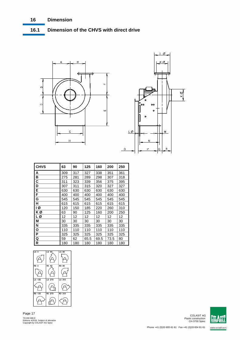
16 Dimension
16.1 Dimension of the CHVS with direct drive
CHVS 63 90 125 160 200 250
A 309 317 327 338 351 361
B 275 281 289 298 307 318
C 311 323 339 356 375 395
D 307 311 315 320 327 327
E 630 630 630 630 630 630
F 400 400 400 400 400 400
G 545 545 545 545 545 545
H 615 615 615 615 615 615
I Ø 120 150 185 220 260 310
K Ø 63 90 125 160 200 250
L Ø 12 12 12 12 12 12
M 30 30 30 30 30 30
N 335 335 335 335 335 335
O 110 110 110 110 110 110
P 325 325 325 325 325 325
Q 59 62 65.5 69.5 73.5 80
R 180 180 180 180 180 180
COLASIT AG Plastic construction
CH-3700 Spiez
Phone +41 (0)33 655 61 61 Fax +41 (0)33 654 81 61
TD-000 680-E Editione 4/2016, Subject of alteration Copyright by COLASIT AG Spiez
Page 18
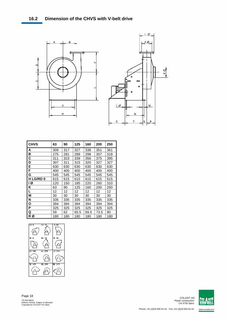
16.2 Dimension of the CHVS with V-belt drive
CHVS 63 90 125 160 200 250
A 309 317 327 338 351 361
B 275 281 289 298 307 318
C 311 323 339 356 375 395
D 307 311 315 320 327 327
E 630 630 630 630 630 630
F 400 400 400 400 400 400
G 545 545 545 545 545 545
H LG/RD 0 615 615 615 615 615 615
I Ø 120 150 185 220 260 310
K 63 90 125 160 200 250
L 12 12 12 12 12 12
M 30 30 30 30 30 30
N 335 335 335 335 335 335
O 394 394 394 394 394 394
P 325 325 325 325 325 325
Q 59 62 65.5 69.5 73.5 80
R Ø 180 180 180 180 180 180
COLASIT AG Plastic construction
CH-3700 Spiez
Phone +41 (0)33 655 61 61 Fax +41 (0)33 654 81 61
TD-000 680-E Editione 4/2016, Subject of alteration Copyright by COLASIT AG Spiez
Page 19
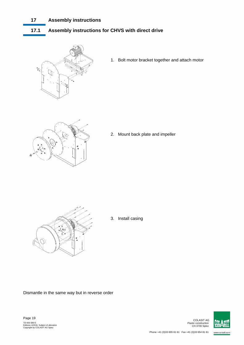
17 Assembly instructions
17.1 Assembly instructions for CHVS with direct drive
1. Bolt motor bracket together and attach motor
2. Mount back plate and impeller
3. Install casing Dismantle in the same way but in reverse order
COLASIT AG Plastic construction
CH-3700 Spiez
Phone +41 (0)33 655 61 61 Fax +41 (0)33 654 81 61
TD-000 680-E Editione 4/2016, Subject of alteration Copyright by COLASIT AG Spiez
Page 20
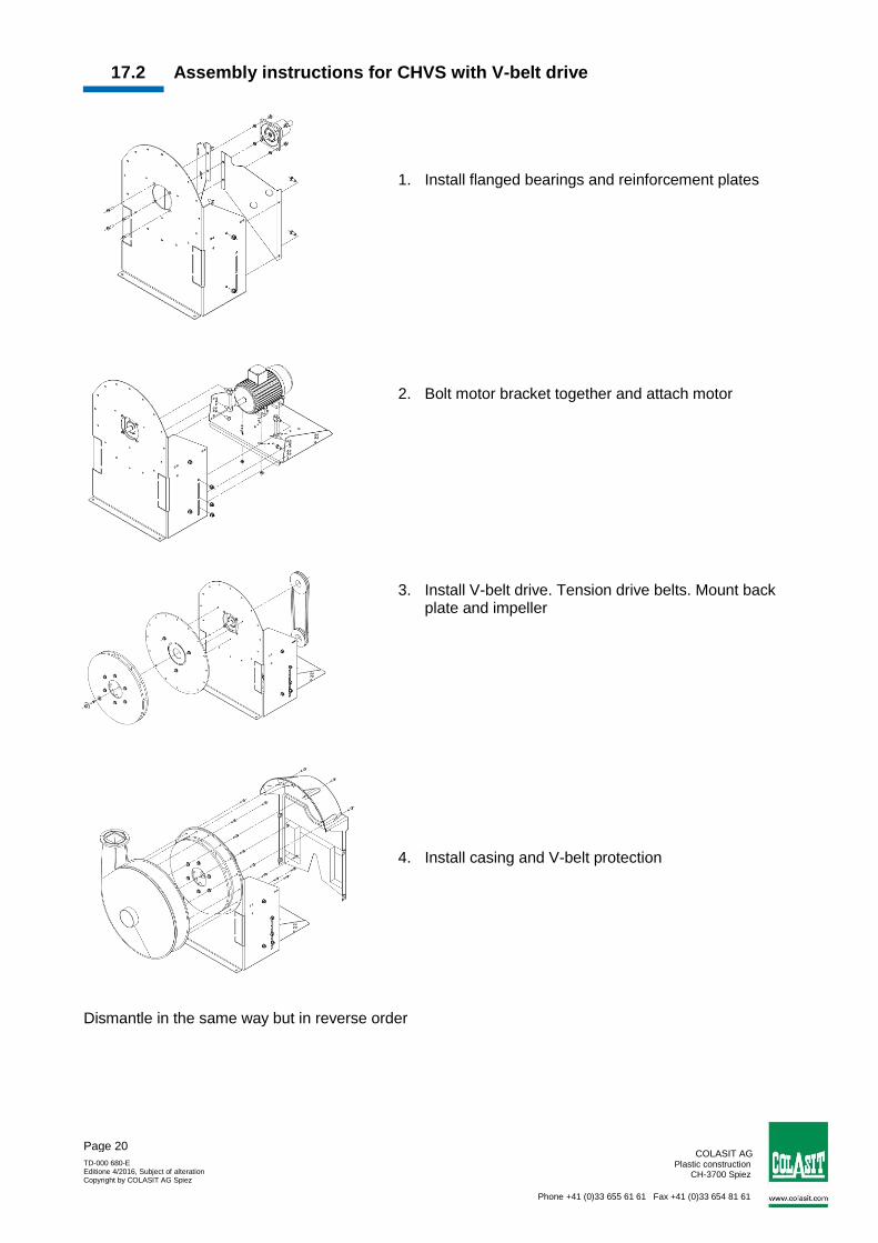
17.2 Assembly instructions for CHVS with V-belt drive
1. Install flanged bearings and reinforcement plates
2. Bolt motor bracket together and attach motor
3. Install V-belt drive. Tension drive belts. Mount back plate and impeller
4. Install casing and V-belt protection Dismantle in the same way but in reverse order
COLASIT AG Plastic construction
CH-3700 Spiez
Phone +41 (0)33 655 61 61 Fax +41 (0)33 654 81 61
TD-000 680-E Editione 4/2016, Subject of alteration Copyright by COLASIT AG Spiez
Page 21
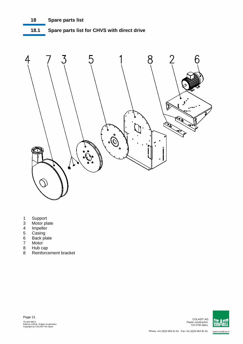
18 Spare parts list
18.1 Spare parts list for CHVS with direct drive
1 Support 3 Motor plate 4 Impeller 5 Casing 6 Back plate 7 Motor 8 Hub cap 8 Reinforcement bracket
COLASIT AG Plastic construction
CH-3700 Spiez
Phone +41 (0)33 655 61 61 Fax +41 (0)33 654 81 61
TD-000 680-E Editione 4/2016, Subject of alteration Copyright by COLASIT AG Spiez
Page 22
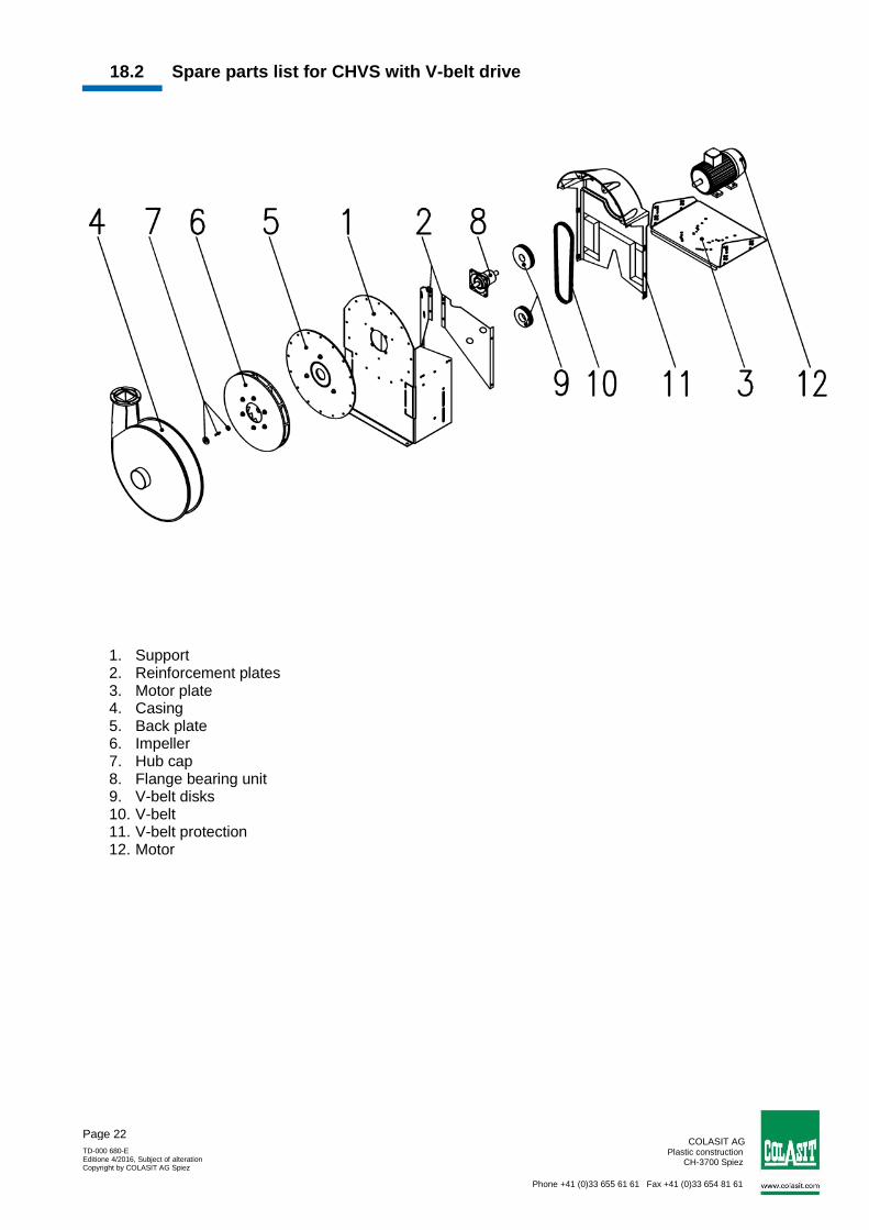
18.2 Spare parts list for CHVS with V-belt drive
1. Support 2. Reinforcement plates 3. Motor plate 4. Casing 5. Back plate 6. Impeller 7. Hub cap 8. Flange bearing unit 9. V-belt disks 10. V-belt 11. V-belt protection 12. Motor
COLASIT AG Plastic construction
CH-3700 Spiez
Phone +41 (0)33 655 61 61 Fax +41 (0)33 654 81 61
TD-000 680-E Editione 4/2016, Subject of alteration Copyright by COLASIT AG Spiez
Page 23
Part 3: Certification
19 Certification
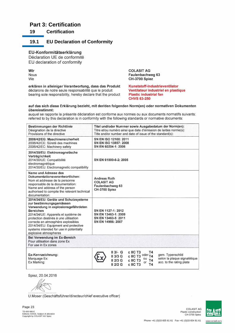
19.1 EU Declaration of Conformity
COLASIT AG Plastic construction
CH-3700 Spiez
Phone +41 (0)33 655 61 61 Fax +41 (0)33 654 81 61
TD-000 680-E Editione 4/2016, Subject of alteration Copyright by COLASIT AG Spiez
Page 24
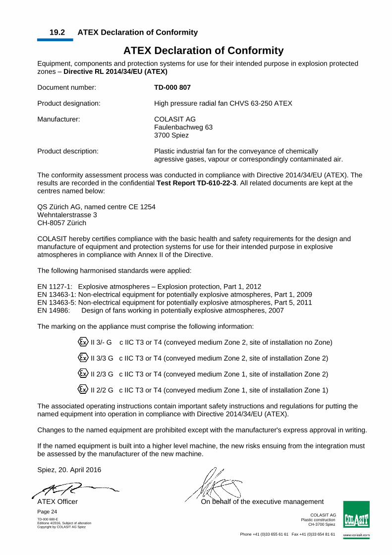
19.2 ATEX Declaration of Conformity
ATEX Declaration of Conformity
Equipment, components and protection systems for use for their intended purpose in explosion protected zones – Directive RL 2014/34/EU (ATEX) Document number: TD-000 807 Product designation: High pressure radial fan CHVS 63-250 ATEX Manufacturer: COLASIT AG Faulenbachweg 63 3700 Spiez Product description: Plastic industrial fan for the conveyance of chemically agressive gases, vapour or correspondingly contaminated air. The conformity assessment process was conducted in compliance with Directive 2014/34/EU (ATEX). The results are recorded in the confidential Test Report TD-610-22-3. All related documents are kept at the centres named below: QS Zürich AG, named centre CE 1254 Wehntalerstrasse 3 CH-8057 Zürich COLASIT hereby certifies compliance with the basic health and safety requirements for the design and manufacture of equipment and protection systems for use for their intended purpose in explosive atmospheres in compliance with Annex II of the Directive. The following harmonised standards were applied: EN 1127-1: Explosive atmospheres – Explosion protection, Part 1, 2012 EN 13463-1: Non-electrical equipment for potentially explosive atmospheres, Part 1, 2009 EN 13463-5: Non-electrical equipment for potentially explosive atmospheres, Part 5, 2011 EN 14986: Design of fans working in potentially explosive atmospheres, 2007 The marking on the appliance must comprise the following information: II 3/- G c IIC T3 or T4 (conveyed medium Zone 2, site of installation no Zone) II 3/3 G c IIC T3 or T4 (conveyed medium Zone 2, site of installation Zone 2) II 2/3 G c IIC T3 or T4 (conveyed medium Zone 1, site of installation Zone 2) II 2/2 G c IIC T3 or T4 (conveyed medium Zone 1, site of installation Zone 1) The associated operating instructions contain important safety instructions and regulations for putting the named equipment into operation in compliance with Directive 2014/34/EU (ATEX). Changes to the named equipment are prohibited except with the manufacturer's express approval in writing. If the named equipment is built into a higher level machine, the new risks ensuing from the integration must be assessed by the manufacturer of the new machine. Spiez, 20. April 2016 ATEX Officer On behalf of the executive management
COLASIT AG Plastic construction
CH-3700 Spiez
Phone +41 (0)33 655 61 61 Fax +41 (0)33 654 81 61
TD-000 680-E Editione 4/2016, Subject of alteration Copyright by COLASIT AG Spiez
Page 25
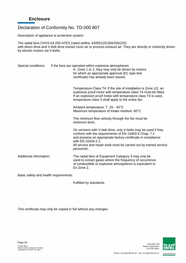
Enclosure
Declaration of Conformity No. TD-000 807
Description of appliance or protective system: The radial fans CHVS 63-250 ATEX (rated widths: 63/90/125/160/200/225) with direct drive and V-belt drive extract room air or process exhaust air. They are directly or indirectly driven by electric motors via V-belts. Special conditions: If the fans are operated within explosive atmospheres in Zone 1 or 2, they may only be driven by motors for which an appropriate approval (EC type test certificate) has already been issued. Temperature Class T4: If the site of installation is Zone 1/2, an explosion proof motor with temperature class T4 must be fitted. If an explosion proof motor with temperature class T3 is used, temperature class 3 shall apply to the entire fan. Ambient temperature: T -20 - 40°C Maximum temperature of intake medium: 60°C The minimum flow velocity through the fan must be minimum 5m/s. On versions with V-belt drive, only V-belts may be used if they conform with the requirements of EN 13463-5 Chap. 7.2 and possess an appropriate factory certificate in compliance with EN 10204-2.1.
All service and repair work must be carried out by trained service personnel.
Additional information: The radial fans of Equipment Category 3 may only be used to extract gases where the frequency of occurrence of combustible or explosive atmospheres is equivalent to Ex-Zone 2. Basic safety and health requirements: Fulfilled by standards. This certificate may only be copied in full without any changes.
COLASIT AG Plastic construction
CH-3700 Spiez
Phone +41 (0)33 655 61 61 Fax +41 (0)33 654 81 61
TD-000 680-E Editione 4/2016, Subject of alteration Copyright by COLASIT AG Spiez
Page 26
19.3 Other certificates The following certificates are enclosed with this operating manual:
Datasheet of the fan
ATEX Certification/Inspection report for fan (see 19.2)
ATEX Certification/Inspection report for electric motor (if this was supplied by COLASIT)
COLASIT AG Plastic construction
CH-3700 Spiez
Phone +41 (0)33 655 61 61 Fax +41 (0)33 654 81 61
TD-000 680-E Editione 4/2016, Subject of alteration Copyright by COLASIT AG Spiez
Page 27
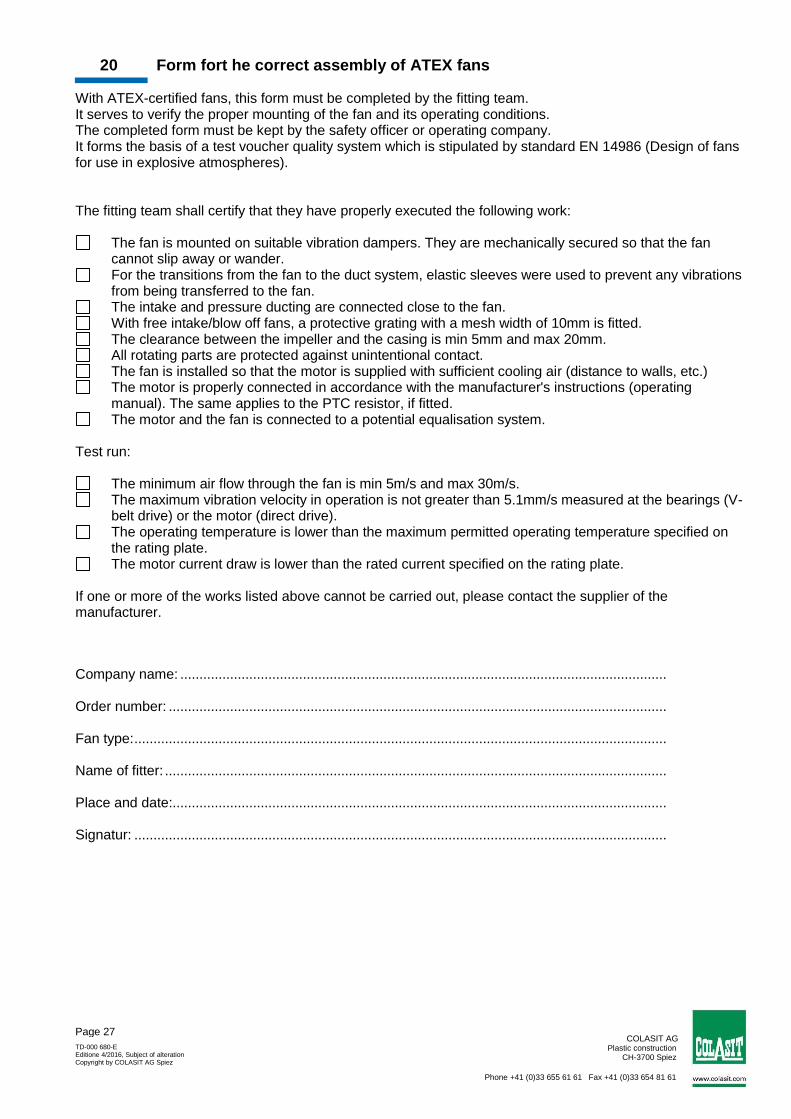
20 Form fort he correct assembly of ATEX fans With ATEX-certified fans, this form must be completed by the fitting team. It serves to verify the proper mounting of the fan and its operating conditions. The completed form must be kept by the safety officer or operating company. It forms the basis of a test voucher quality system which is stipulated by standard EN 14986 (Design of fans for use in explosive atmospheres). The fitting team shall certify that they have properly executed the following work:
The fan is mounted on suitable vibration dampers. They are mechanically secured so that the fan cannot slip away or wander.
For the transitions from the fan to the duct system, elastic sleeves were used to prevent any vibrations from being transferred to the fan.
The intake and pressure ducting are connected close to the fan. With free intake/blow off fans, a protective grating with a mesh width of 10mm is fitted. The clearance between the impeller and the casing is min 5mm and max 20mm. All rotating parts are protected against unintentional contact. The fan is installed so that the motor is supplied with sufficient cooling air (distance to walls, etc.) The motor is properly connected in accordance with the manufacturer's instructions (operating
manual). The same applies to the PTC resistor, if fitted. The motor and the fan is connected to a potential equalisation system.
Test run:
The minimum air flow through the fan is min 5m/s and max 30m/s. The maximum vibration velocity in operation is not greater than 5.1mm/s measured at the bearings (V-
belt drive) or the motor (direct drive). The operating temperature is lower than the maximum permitted operating temperature specified on
the rating plate. The motor current draw is lower than the rated current specified on the rating plate.
If one or more of the works listed above cannot be carried out, please contact the supplier of the manufacturer.
Company name: ............................................................................................................................... Order number: .................................................................................................................................. Fan type: ........................................................................................................................................... Name of fitter: ................................................................................................................................... Place and date:................................................................................................................................. Signatur: ...........................................................................................................................................