Introduction The EFU Converters are designed to convert different interfaces into other interfaces (e.g. Ethernet, Fiber optic, USB). They are available in different variants. A typical application are the extension of Ethernet interfaces for use with long distances via fiber optic cable or the extension of a existing ASD (application supporting device) with a additional network interface. The EFU supports 10Base-T, 100Base-Tx, 100Base-Fx and the IEEE802.3 specification, supports also Half/Full-dupplex UTP Auto-Negociation. Automatically detects and adjusts crossover function. The EFU - 1 - 2 - 3 consist of two together mounted housings, when the suffix - 2 is: “-E” and consist of one housing when the suffix - 2 is : “-C”. The EFU Converters are developed for use in hazardous area Zone 1 and Zone 21. The EFU NEX variant for use in non hazardous area only.
Available EFU -1-2-3 models Various models of EFU-1-2-3 can be supplied:
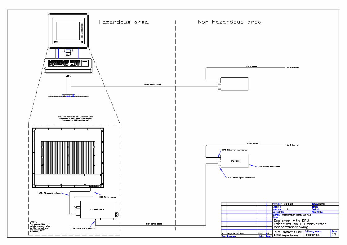
-1 = EF: Variant EF, Ethernet to fiber optic converter for use in hazardous areas. This model can be used to extend the Ethernet interface up to 5km (other distances on request) by using fiber optic signals.
UE: Variant UE, USB to Ethernet converter for use in hazardous areas. This model can be used to realize an additional Network-card.
UEF: Variant UEF, USB to Ethernet, to fiber optic for use in hazardous areas. This model can be used to realize an additional Network card and extend it up to 5km (other distances on request) by using fiber optic signals
NEX: Variant NEX, NON Ex, Ethernet to fiber optic converter for use in non hazardous areas. This model is specially ATEX and IECEx certified to receive/send fiber optical signals coming/going into/from hazardous areas. This model is located in non hazardous areas.
- 2 = E: With integrated Ex e connections box.
C: connections cable only (Without integrated Ex e connections box).
- 3 = AC : Supplied with 100-250VAC(max.)/ 50 - 60 Hz DC24: Supplied with 20-30 VDC, DC5: Supplied with external 5VDC.
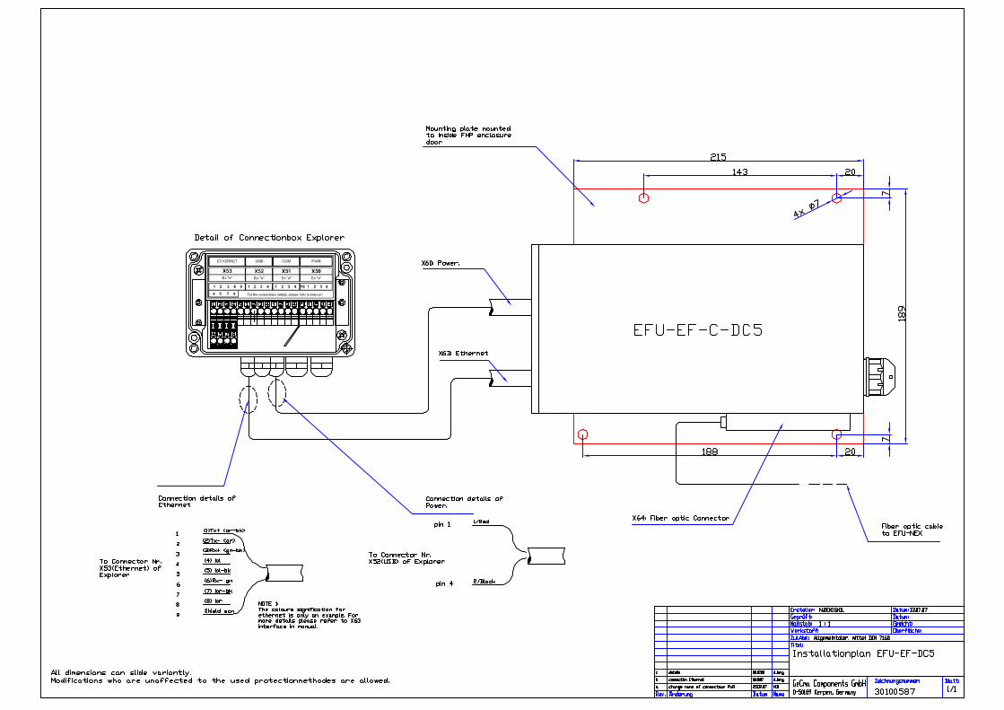
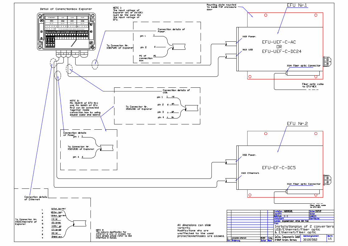
Example: EFU-EF-C-DC5 = Ethernet to Fiber optic converter, without connection box Ex e Supplied with 5VDC. For more details please refer to the attached drawings Nr. # 30100588 and #30100587.
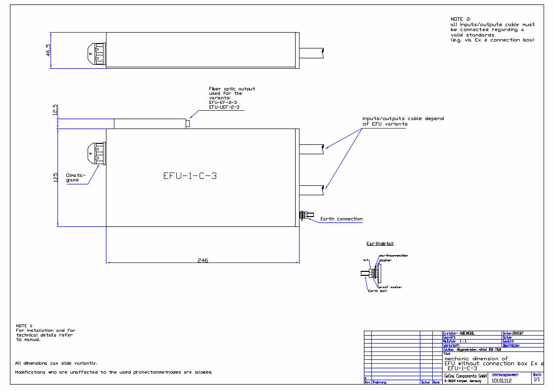
The assembly and the connections of the inputs/outputs cables depend of EFU -1-2-3 models. For mechanical details please refer to the attached drawings Nr.
# 10101111= dimensions details of EFU with connection box Ex e # 10101112= dimensions details of EFU without connection box Ex e
EFU Model Converter signification Description on attached Drawing Nr.:
EFU-EF-C-DC5 Ethernet to Fiber optic 30100588 and 30100587 EFU-UE-C-DC5 USB to Ethernet 30100589 and 30100586 EFU-UEF-C-AC or EFU-UEF-C-DC24
USB-Ethernet to Fiber optic.
30100590 and 30100582
EFU-NEX Ethernet to fiber optic for use in non hazardous areas
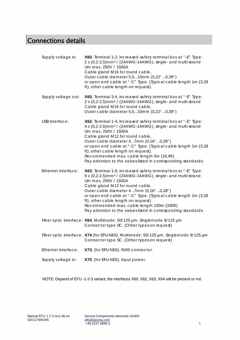
Supply voltage in: X60, Terminal 1-2, increased safety terminal box at “-E” Type:
2 x (0,2-2,5)mm² / (24AWG-14AWG), single- and multi-strand Um max. 250V / 1500A Cable gland M16 for round cable, Outer cable diameter 5,5...10mm (0,22“...0,39“) or open end cable at “-C” Type. (Typical cable length 1m (3,28 ft), other cable length on request).
Supply voltage out: X60, Terminal 3-4, increased safety terminal box at “-E” Type: 2 x (0,2-2,5)mm² / (24AWG-14AWG), single- and multi-strand Cable gland M16 for round cable, Outer cable diameter 5,5...10mm (0,22“...0,39“)
USB Interface: X62, Terminal 1-4, increased safety terminal box at “-E” Type:
4 x (0,2-2,5)mm² / (24AWG-14AWG), single- and multi-strand Um max. 250V / 1500A Cable gland M12 for round cable, Outer cable diameter 4...7mm (0,16“...0,28“) or open end cable at “-C” Type. (Typical cable length 1m (3,28 ft), other cable length on request). Recommended max. cable length 5m (16,4ft) Pay attention to the values listed in corresponding standards.
9 x (0,2-2,5)mm² / (24AWG-14AWG), single- and multi-strand Um max. 250V / 1500A Cable gland M12 for round cable, Outer cable diameter 4...7mm (0,16“...0,28“) or open end cable at “-C” Type. (Typical cable length 1m (3,28 ft), other cable length on request). Recommended max. cable length 100m (330ft) Pay attention to the values listed in corresponding standards.
Terminal Connections NOTE: Depend of EFU -1-2-3 variant, the interfaces X60, X62, X63, X64 will be present or not. Supply voltage interface X60:
Connection Significance 100-250VAC(max)
AC variant 24VDC variant 5VDC Variant
X60-1 Supply circuit L
Supply circuit 20…30VDC ±10%
Supply circuit 5VDC ±10%
X60-2 Supply circuit N
Supply circuit 0V DC
Supply circuit 0V DC
X60-3 Output circuit L
Output circuit 20…30VDC ±10%
Output circuit 5VDC ±10%
X60-4 Output circuit N
Output circuit 0V DC
Output circuit 0V DC
X60-5 PE PE PE The device are supplied via the Supply circuit. The Output circuit are integrated to supply optional other devices. The Supply circuit and the Output circuit are connected parallel. This option exist only for EFU-1-E-3 variants.
USB Interface X62:
Connection Significance Signal Prefered color
X62-1 +UB rd X62-2 D- wh X62-3 D+ gn X62-4 GND bk
Ethernet interface X63:
Connection Significance
Signal Preferred colour
Preferred colour CH
X63-1 (1) TX+ wh/or bk X63-2 (2) TX- or gn X63-3 (3) RX+ wh/gn rd X63-4 (4) bl wh X63-5 (5) wh/bl bl X63-6 (6) RX- gn or X63-7 (7) wh/br ye X63-8 (8) br br X63-9 Shield Shield Shield
Fiber: Multimode SC 50/125um up to 5km Singlemode SC 9/125um up to 15km
USB: Version 1.1 / 2.0
Supply: AC : Supplied with 100-250VAC(max)/ 50 - 60 Hz / 1A DC24: Supplied with 20-30 VDC / 1A DC5: Supplied with external 5VDC / 1A Depend of EFU -1-2-3 variants, the corresponding technical data will vary.
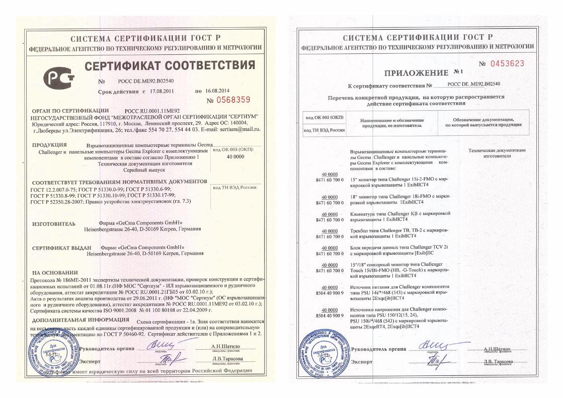
ATEX Certification for EFU -1-2-3 :
Zone 1 Zone 21
ATEX ignition protection:
EFU-EF-E-3 EFU-UEF-E-3
Ex II 2(1)G Ex e q [op is] IIC T4 Ex II 2(1)D Ex tD A21 IP64 T130°C
EFU-UE-E-3 Ex II 2G Ex e q II T4 Ex II 2 D Ex tD A21 IP64 T130°C
EFU-EF-C-3 EFU-UEF-C-3
Ex II 2(1)G Ex q [op is] IIC T4 Ex II 2(1)D Ex tD A21 IP64 T130°C
EFU-UE-C-3 Ex II 2G Ex q II T4 Ex II 2 D Ex tD A21 IP64 T130°C
Operating temperature: (10 to 90% rel. humidity, n. c.)
Ta: -20°C ... +60°C (-4°F to 140°F)
Ta: -20°C ... +60°C (-4°F to 140°F)
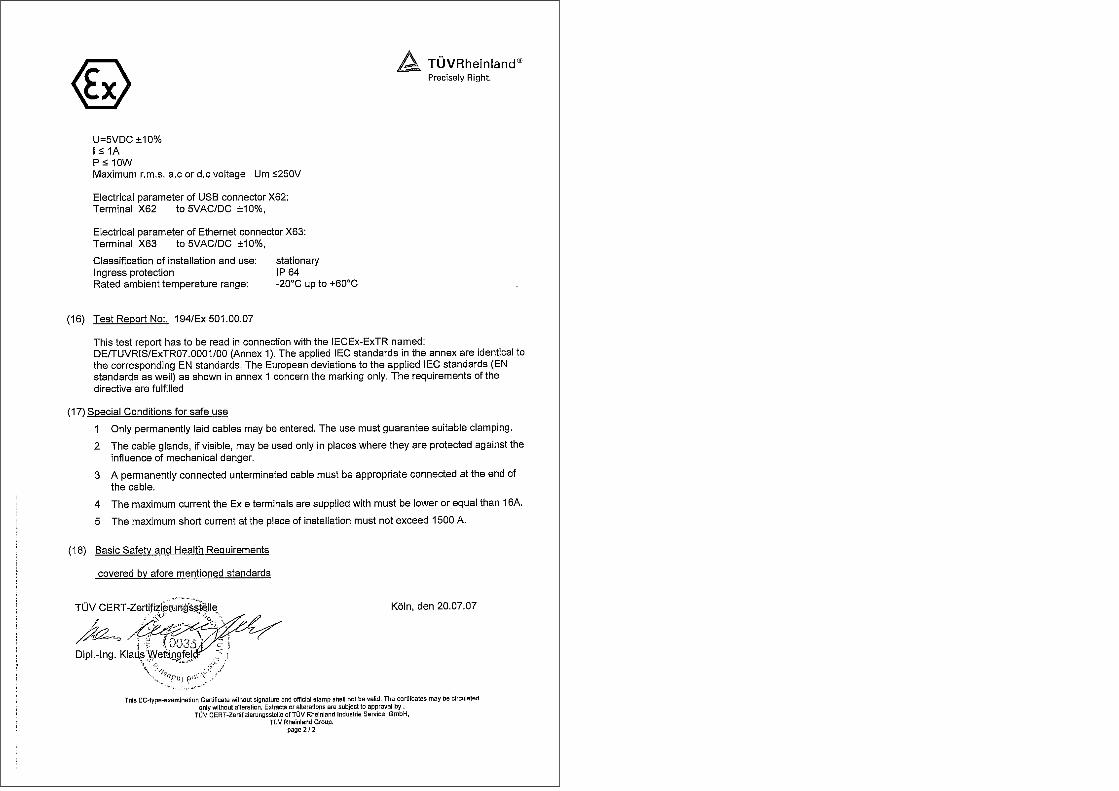
Certificate: ATEX TÜV 07 ATEX 7501 X TÜV 07 ATEX 7501 X
ATEX Certification for EFU NEX :
For use in non hazardous areas ATEX ignition protection: Ex II (1) GD [op is T4 Ga] IIC Operating temperature: (10 to 90% rel. humidity, n. c.)
Ta: -20°C ... +60°C (-4°F to 140°F)
Certificate: ATEX TÜV 07 ATEX 7501 X
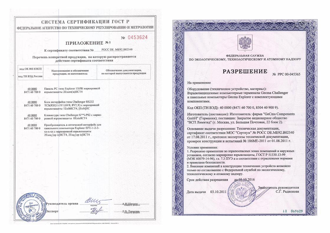
Further details can be found in the attached license.
Safety Instructions General Safety Instructions The instructions stated in this chapter are to be followed accurately to ensure a safe and reliable operation.
The certificate and the special conditions included in it are to be observed.
Follow the national safety regulations and the accident prevention regulations.
The installation is only to be performed by specialists. These specialists must be familiar with the characteristics of explosion-endangered facilities. Incorrect or inadmissible application as well as non-observance of the instructions of this operating manual make the guarantee void.
Only use this device for the approved purpose. Conversions and modifications to the device are inadmissible. The housing is only to be opened by the company Gecma Components GmbH.
Assembly
The national assembly and installation regulations are to be observed.
The generally accepted rules of engineering are to be observed.
The entire equipment is to be connected and operated correctly and properly according to the applicable standards, guidelines and installation instructions.
The housing is to be grounded via grounding equipment. Grounding must be effected with a core cross section of at least 4mm².
Shielded cables are recommended for use in combination with this device.
Connect the device via the Ex e terminal enclosure when complete de-energized. Do not open the terminal enclosure when the device is powered and live. Ensure the power supply is isolated. The cable diameter has to comply to the specification of the terminals. The outer diameter of the cables has to comply to the specification of the cable glands. Tighten the Cable glands according to the rules. Seal not used Cable glands. The Cable glands of the Ex e terminal enclosure have to comply to the national standards and have to be interchanged if necessary.
The device is only to be connected in a de-energized condition.
If the device in a dust atmosphere is to be replaced, the device and/or the housing, in which the device is installed, is to be de-energized first and if necessary cooled according to the regulations. Before opening the device and/or housing and during period in which the device and/or the housing is open, the environment of the device and/or housing has to be kept dust-free to such an extent that no dust can enter the interior of the housing. When installing new components, observe that all seals are in a flawless condition and function properly.
Before putting the device into operation, make sure that the device has been installed as prescribed and that the device and its wiring are not damaged. Operation
The device is only to be operated in an undamaged and clean condition.
If the device has suffered any damages which might affect the international protection (e.g. cracks, holes or broken components) it must be taken out of service immediately. The device can only be put into operation again after the defect components have been exchanged. When the device is damaged, do not touch it any longer! Risk of injury!
If the device is to be used in a dust atmosphere dust layers >5mm have to be removed.
In the event of non-observance & non-compliance the stipulated explosion protection cannot be guaranteed and/or the guarantee will become void!
Modifications require the written approval by the company GeCma Components GmbH.
General Instructions Before starting the assembly read the entire operating manual! In cases of doubt (in the form of mistranslation) the German operating manual is to be applied. We do not assume liability for misprints and errors in this operating manual. The housings shall only be opened by personnel of Gecma Components GmbH. Should you have any questions or suggestions please feel free to contact us any time: GeCma Components GmbH Heisenbergstraße 26 – 40 D-50169 Kerpen Tel.: +49 (0)22 37 / 69 96 0 Fax: +49 (0)22 37 / 69 96 99 mailto:[email protected] http://www.gecma.com Technical progress The manufacturer reserves the right to adjust all technical data without special announcement according to the technical progress. Repair work, hazardous material The description of the respective fault(s) is in any case to be included with the devices which are sent to GeCma Components GmbH for repair. The following measures are to be taken before sending a device in for repair: Please remove the entire adhering medium residue. Pay special attention to sealing grooves and gaps which might contain medium residue. We have to ask you to refrain from sending the device back if it is impossible for you to definitely guarantee that all health-endangering material has completely been removed. Costs which arise due to inadequate cleaning of the device for a potential disposal or for personal injury (cauterisation, etc.) will be charged to the proprietor of the device. Used trademarks AT, IBM and PS/2 are registered trademarks of the International Business Machines Corporation. Microsoft, Windows and Windows NT are registered trademarks of Microsoft Corporation. All other trademarks mentioned and depicted in the text are trademarks of the respective owners and are recognized as registered.