Page 1
Operating Manual
Fine Dust Monitor System
Fidas®
F i d a s ® 1 0 0
F i d a s ® 2 0 0 / 2 0 0 S
F i d a s ® 3 0 0 / 3 0 0 S
Model 100/200/300 Model 200 S/300 S
Phone +49 (0)721 96213-0
Fax +49 (0)721 96213-33
[email protected]
www.palas.de
PALAS GmbH
Partikel- und Lasermesstechnik
Greschbachstrasse 3b
76229 Karlsruhe
Page 2
OPERATING MANUAL FIDAS® FINE DUST MONITOR SYSTEM
PALAS® GMBH, VERSION V0020312 2
CONTENTS
1 INSTALLATION AND FIRST OPERATION ............................................................................ 4
1.1 Mains voltage check ...................................................................................................... 4
1.2 Check of the completeness of delivery ........................................................................... 4
1.3 Equipment overview ...................................................................................................... 7
1.3.1 Front panel of the Fidas® control unit ..................................................................... 7
1.3.2 Back side of the Fidas® control unit ......................................................................... 8
1.3.3 Connections on the back side of the Fidas® control unit .......................................... 9
1.4 First measurement....................................................................................................... 10
2 FIDAS 200 S / FIDAS 300 S – IMPLEMENTATION OF THE COMPONENTS IN THE IP-65 WEATHER-
PROTECTIVE HOUSING ..................................................................................................................... 12
2.1 Mounting of the weather station ................................................................................. 12
2.2 Mounting of the antenna ............................................................................................. 14
2.3 Mounting of the sampling tube .................................................................................... 14
2.4 Insertion of the Fidas® control unit .............................................................................. 15
2.5 Mounting of the Sigma-2 sampling head ...................................................................... 19
2.6 Final handholds ........................................................................................................... 19
3 CALIBRATION/ VERIFICATION OF THE FIDAS® ........................................................................... 21
3.1 Automatic offset adjustment ....................................................................................... 21
3.2 Check of the tightness of the total system .................................................................... 21
3.3 Adjustment of the sensitivity of the particle sensor ...................................................... 21
3.4 Check of the particle flow in the particle sensor ............................................................ 22
3.5 Check of the volume flow ............................................................................................ 22
4 DEMOUNTING / EXCHANGING THE GRAVIMETRIC FILTER ......................................................... 25
5 CLEANING THE FIDAS® SYSTEM ................................................................................................. 26
5.1 How to clean the sensor............................................................................................... 26
5.1.1 For Fidas®
200/200 S and Fidas® 300/300 S Systems ............................................... 26
5.1.2 For all Fidas® Systems ........................................................................................... 26
5.2 How to clean the suction filter of the internal pump ..................................................... 28
6 PARTICLE MEASUREMENT WITH THE FIDAS® SYSTEM ............................................................... 29
6.1 Special features of the Fidas® system ........................................................................... 29
6.2 Clear calibration curve ................................................................................................. 30
6.3 High resolution capacity............................................................................................... 31
6.4 Basic definitions in measurement technology ............................................................... 31
6.5 Effects of the device’s characteristics ........................................................................... 32
7 ENSURING CORRECT MEASUREMENT CONDITIONS .................................................................. 33
8 TECHNICAL DATA FIDAS® SYSTEM: ............................................................................................ 34
9 ANNEXES:................................................................................................................................ 35
9.1 IP-65 weather-protective housing for Fidas® System: .................................................... 35
9.2 Aerosol humidity compensation module IADS .............................................................. 36
9.3 Sigma-2 sampling head ................................................................................................ 37
9.4 Compact weather station WS600-UMB ........................................................................ 37
9.4.1 Technical data WS600-UMB .................................................................................. 39
10 READER’S COMMENTS SHEET .................................................................................................. 40
Page 3
OPERATING MANUAL FIDAS® FINE DUST MONITOR SYSTEM
PALAS® GMBH, VERSION V0020312 3
IMPORTANT NOTES !!!
• Please check immediately after unpacking the instrument if there are obvious
transportation damages. If any damages of the instrument are visible, don’t connect it
to mains and don’t switch it on. Call the manufacturer to check if the instrument can be
operated safely.
• It is essential to read the operating instructions thoroughly before operating Fidas®!!
• The manufacturer is not liable for damages caused by improper operating, incorrect
cleaning or the measurement of aerosols with a gas condition or composition the
instrument is not specified for.
• The instrument may only be operated in dry rooms under atmospheric environmental
pressure at temperatures between 0°C and +40°C.
The manufacturer will not be liable with regard to the operating guarantee, if operating
takes place under different environmental conditions, such as corrosive or explosive
environment, electric or electromagnetic fields, operating within areas of ionising
radiation, within areas conductive to shock or vibration.
• To switch-off Fidas®, use the "shut down" button; Fidas® shuts down then
automatically. Do not switch-off the mains switch, before the operating system shut
down automatically!!!
• Fidas® was manufactured for the system voltage defined in the correspondent order.
Please check if the system voltage indicated on the identification plate corresponds to
the system voltage at the place of operation.
Only use original spare parts! Please contact the manufacturer to order spare parts.
• Attention: Aerosols might be dangerous to your health. That’s why they ought not to be
inhaled. It might also be necessary to wear protective clothes (dust mask). Please pay
attention to the correspondent standards and safety rules.
• General information on optical particle counters, such as resolution capacity, detection
limit and counting efficiency, can be found in the VDI-guideline 3489, Part 3.
Page 4
OPERATING MANUAL FIDAS® FINE DUST MONITOR SYSTEM
PALAS® GMBH, VERSION V0020312 4
1 Installation and first operation
1.1 Mains voltage check
The Fidas® was set by the manufacturer to the mains voltage requested in the order. Please
verify, if the mains voltage indicated on the type label corresponds to the mains voltage at
the respective place of the installation.
The manufacturer is not liable for damages resulting from operation with improper mains
voltage!!!
1.2 Check of the completeness of delivery
For the transport by a forwarding company, the Fidas® system was decomposed in its
components. Before the first operation, the system has to be recomposed. The following
parts should be available:
Fig. 1 A+B: on the left components of a Fidas® system, on the right IP-65 weather protective
housing
For all versions, the following components and documentation should be available (the
letters in parenthesis refer to the indications in figure 1):
- Fidas® control unit (a)
- Aerosol inlet tube (f)
- Power cable (h)
- Plastic tube ca. 30 cm for calibration and verification
- 1 bottle CalDust 1100 for calibration and verification
- Refill pack CalDust 1100
- Cleaning kit with optical wipes
(a) (j)
(h)
(e)
(d)
(b)
(i)
(g)
(m)
(k)
(c)
(f)
Page 5
OPERATING MANUAL FIDAS® FINE DUST MONITOR SYSTEM
PALAS® GMBH, VERSION V0020312 5
- Manual Fidas® Fine Dust Monitor System (printed)
- Description Fidas® Firmware (printed)
- Manual PDAnalyze (printed)
- Manual weather station WS300-UMB
- Calibration certificate (printed)
- CD or USB flash drive with evaluation software PDAnalyze
- Serial cable (null-modem)
- Pointer for touchscreen
Depending on the model, the following components are additionally included in the delivery:
Only Fidas® 100:
- Sensor for temperature, relative humidity and pressure
Only Fidas® 200:
- Weather station WS300-UMB (d) – optional instead also WS600-UMB (m)
- Sampling tube with IADS (c)
- Connection sampling head to sampling tube (e)
- Sampling head Sigma-2 (b) – optional instead or additional also PM-10 or PM-2,5
sampling head (k)
- Fixing of the sampling tube at the housing (i)
Only Fidas® 200 S:
- Weather station WS300-UMB (d) – optional instead also WS600-UMB (m)
- Sampling tube with IADS (c)
- Connection sampling head to sampling tube (e)
- Sampling head Sigma-2 (b) – optional instead or additional also PM-10 or PM-2,5
sampling head (k)
- 2x Fixing of the sampling tube and the weather station tube at the housing (i)
- Tube for weather station (j)
- Antenna (g)
- IP-65 weather-protective housing
Only Fidas® 300:
- Weather station WS300-UMB (d) – optional instead also WS600-UMB (m)
- Sampling tube with IADS (c)
- Connection sampling head to sampling tube (e)
- Sampling head Sigma-2 (b) – optional instead or additional also PM-10 or PM-2,5
sampling head (k)
Page 6
OPERATING MANUAL FIDAS® FINE DUST MONITOR SYSTEM
PALAS® GMBH, VERSION V0020312 6
- Fixing of the sampling tube at the housing (i)
- Big pump for volume flow 2,3 m3/h
Only Fidas® 300 S:
- Weather station WS300-UMB (d) – optional instead also WS600-UMB (m)
- Sampling tube with IADS (c)
- Connection sampling head to sampling tube (e)
- Sampling head Sigma-2 (b) – optional instead or additional also PM-10 or PM-2,5
sampling head (k)
- 2x Fixing of the sampling tube and the weather station tube at the housing (i)
- Tube for weather station (j)
- Antenna (g)
- Big pump for volume flow 2.3 m3/h
- IP-65 weather-protective housing
Page 7
OPERATING MANUAL FIDAS® FINE DUST MONITOR SYSTEM
PALAS® GMBH, VERSION V0020312 7
1.3 Equipment overview
1.3.1 Front panel of the Fidas® control unit
Fig. 2: Front panel of the Fidas® control unit
The Fidas® system is operated via the touch display (please see separate manual Fidas®
Firmware for detailed information).
The data can be readout via the USB connection and processed further on an external PC
with the additional PDAnalyze software (included in the delivery).
Filter unit for protection
of the internal pump
Pump connection
USB connection
Aerosol sensor, integrated
into the control unit Touch display
Aerosol inlet
Gravimetric
filter holder
Page 8
OPERATING MANUAL FIDAS® FINE DUST MONITOR SYSTEM
PALAS® GMBH, VERSION V0020312 8
1.3.2 Back side of the Fidas® control unit
Fig. 3: Back side of the Fidas® control unit
The control unit is switched on and off with the mains switch.
There are two fuses, T 2 A / 250 V, at the back side.
The LED is switched on by the mains switch. The operating hour counter runs as long as the
device is switched on. The lamp has a life cycle of > 20,000 operating hours.
Connection for IADS
aerosol humidity
compensation module
External sensors‘
connection:
- temperature
- relative humidity
Mains switch and
mains connection
Operating
hour counter
Outlet for sampling
volume flow
USB connec-tion
for printer, key-
board and mouse
Network
connection
RS 232 connection for
Modbus connection
Connection for weather
station WS600-UMB
Fuse
External sensor
connection:
- barometric pressure
Page 9
OPERATING MANUAL FIDAS® FINE DUST MONITOR SYSTEM
PALAS® GMBH, VERSION V0020312 9
1.3.3 Connections on the back side of the Fidas® control unit
On the right, there are the following connection possibilities:
• Network, to connect the Fidas® System to a network, e.g. for remote service and for
transfer of software updates.
• USB connection, e.g. for a printer, keyboard, mouse or USB stick.
• Modbus via RS 232 connection for remote enquiry of the measured values and
external control of the measurement device (WebAccess).
• Connection for weather station WS600-UMB (Fidas® 200 S and Fidas® 300 S
systems) for recording of:
� wind speed
� wind direction
� precipitation quantity
� type of precipicitation
� temperature
� humidity
� pressure
• Connection for external sensors for recording the temperature and relative humidity
• Connection for external sensor for recording the barometric pressure
• Connection for aerosol humidity compensation module IADS
(Intelligent Aerosol Drying System)
Fig. 4: Connection possibilities on the back side of the Fidas® control unit
Connection for IADS aerosol
humidity compensation
module
External sensors‘
connection:
- temperature
- relative humidity
External sensor connection:
- barometric pressure
free
USB connection
Network connection
RS 232 connection for
Modbus connection
Connection for weather
station WS600-UMB
Page 10
OPERATING MANUAL FIDAS® FINE DUST MONITOR SYSTEM
PALAS® GMBH, VERSION V0020312 10
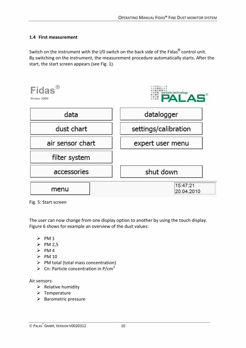
1.4 First measurement
Switch on the instrument with the I/0 switch on the back side of the Fidas® control unit.
By switching on the instrument, the measurement procedure automatically starts. After the
start, the start screen appears (see Fig. 1).
Fig. 5: Start screen
The user can now change from one display option to another by using the touch display.
Figure 6 shows for example an overview of the dust values:
� PM 1
� PM 2,5
� PM 4
� PM 10
� PM total (total mass concentration)
� Cn: Particle concentration in P/cm3
Air sensors:
� Relative humidity
� Temperature
� Barometric pressure
Page 11
OPERATING MANUAL FIDAS® FINE DUST MONITOR SYSTEM
PALAS® GMBH, VERSION V0020312 11
Fig. 6: Data overview, e.g. PM values
Please see separate manual Fidas® Firmware for detailed information.
Page 12
OPERATING MANUAL FIDAS® FINE DUST MONITOR SYSTEM
PALAS® GMBH, VERSION V0020312 12
2 Fidas 200 S / Fidas 300 S – Implementation of the components in the IP-65
weather-protective housing
2.1 Mounting of the weather station
The shorter stainless steel tube is the mounting of the weather station. You need the
following components:
- Short stainless steel tube
- Fixing of the tube at the housing
- Weather station WS300-UMB – or optional instead WS600-UMB
You need the following tools:
- 13 mm open-end wrench
- 40 mm open-end wrench or adjustable tongs
Figure 7 shows the components of the fixing. Please take care that the sealing rings are also
used and that they are in an undamaged condition. These rings serve as sealing in order to
avoid that water enters the housing. If water enters from outside the housing, it is possible
that the control unit is damaged or even that the Fidas® breaks down.
Palas® assumes no liability for damages arising from a leak in the fixing.
Fig. 7: Components of the fixing of the weather station tube
Please make sure that all components are available. Then, combine the first 5 components
(from left to right in figure 7) and move them over the tube (there is a cover on the top and
under it there is the passage for the cable to the weather station. Then proceed with this
part of the fixing and the lower part of the tube from the outside through the left rear
opening of the weather-protective housing.
Then attach from inside first the sealing ring (shown in Figure 7, far right) and then the thin
nut (second from right in figure 7). Then screw tightly both the inner and outer nut with a
wrench or adjustable tongs.
Page 13
OPERATING MANUAL FIDAS® FINE DUST MONITOR SYSTEM
PALAS® GMBH, VERSION V0020312 13
Fig. 8: Fixing of the weather station tube
Figure 8 shows how the fixing of the weather station tube should look like.
Before mounting the weather station at the tube, please verify that the tube has a cover on
the top. Then slide the weather station on the tube (figure 9) and tighten the nuts slightly
(the weather station must rotate easily!).
Fig. 9: Mounting of the weather station at the tube
Set up the weather station to the north of.
Then tighten the two nuts on alternate so tight that the weather station can no longer move.
Attention: if you tighten the nuts too tight, the mounting of the weather station can split!
Then, connect the cable with the weather station (hand-tight!) as shown in figure 10.
Page 14
OPERATING MANUAL FIDAS® FINE DUST MONITOR SYSTEM
PALAS® GMBH, VERSION V0020312 14
Fig. 10: Connection of the cable with the weather station
2.2 Mounting of the antenna
The antenna consists of a plastic part that has to be mounted at the outside of the housing, a
sealing ring, a serrated washer, a nut and a cable as shown in figure 11.
Fig. 11: The antenna
Direct the cable from the outside through the small hole on the top of the housing. Then
attach the antenna from the inside by means of the serrated washer and the nut.
Make also sure that the sealing ring seals the opening, but do not tighten the nut too tight as
the plastic may crack then.
2.3 Mounting of the sampling tube
For the mounting of the sampling tube at the weather-protective housing, the same fixing is
used than for the mounting of the weather station tube. Figure 6 shows the components.
The sampling tube includes the heating for the IADS (intelligent aerosol drying system),
therefore a cable is connected.
First, direct the bottom end with the cable from the outside through the hole on the right
front (see figure 12). Then place the first sampling tube on the base of the control unit (not
on the control unit itself).
Page 15
OPERATING MANUAL FIDAS® FINE DUST MONITOR SYSTEM
PALAS® GMBH, VERSION V0020312 15
Fig. 12: Insert the sampling tube
Then slide the outer parts of the fixing on the sampling tube.
Figure 13 shows how the rubber gasket is directed from the top in the gray sleeve. What
remains are still the big outer nut which is mounted only at the very end, and the sealing ring
and the nut, which are inserted from the inside.
Fig. 13 A+B: Outer fixing of the sampling tube
Then attach first the remaining thin ring via the cable from the inside and then the thin nut
at the rest of the fixing. Tighten the nut.
However, please take care that sampling tube can still move for the later installation of the
Fidas® control unit.
2.4 Insertion of the Fidas® control unit
First, plug the aerosol inlet tube into the opening on the sensor head (figure 14).
Page 16
OPERATING MANUAL FIDAS® FINE DUST MONITOR SYSTEM
PALAS® GMBH, VERSION V0020312 16
Fig. 14 A+B: Mounting of the aerosol inlet tube
Lift the Fidas® control unit carefully and insert it as shown in figure 15 into the weather-
protective housing and place it on the platform.
Fig. 15: Insertion of the Fidas® control unit
Then connect the cables from the weather station and the IADS (sampling tube) with the
appropriate and designated ports (places shown in figure 16 can vary depending on model).
Also, connect the power cable (and possibly a network cable), but do not switch the Fidas®
on!
Page 17
OPERATING MANUAL FIDAS® FINE DUST MONITOR SYSTEM
PALAS® GMBH, VERSION V0020312 17
Fig. 16: Connection of the weather station, IADS with the ports on the back side
Then place the control unit so that you are exactly under the sampling tube with the opening
of the sampling inlet tube. You must have previously lifted the sampling tube. Then direct
carefully (!) the sampling tube through the sampling inlet guide tube as shown in Figure 17.
The sampling tube should be as vertical as possible, if necessary, please change the position
of the control unit accordingly.
Fig. 17: Connection of the sampling tube with the sampling inlet tube and the control unit
Continue like this until the sampling tube rests on the sensor unit, i.e. there should be no
gap. Figure 18 B shows the correct position.
Page 18
OPERATING MANUAL FIDAS® FINE DUST MONITOR SYSTEM
PALAS® GMBH, VERSION V0020312 18
Fig. 18 A+B: on the left wrong position of the sampling tube, on the right correct position
Then mount carefully the brackets of the mounting:
Fig. 19: Internal fixing of the sampling tube
Then slide the large remaining nut of the fixation of the sampling tube over the rest and
tighten it (figure 20). Make also sure that sealing ring seals the opening.
Fig. 20 A+B: Final fixing of the sampling tube
Incorrect!
Existing gap
Correct!
No gap
Page 19
OPERATING MANUAL FIDAS® FINE DUST MONITOR SYSTEM
PALAS® GMBH, VERSION V0020312 19
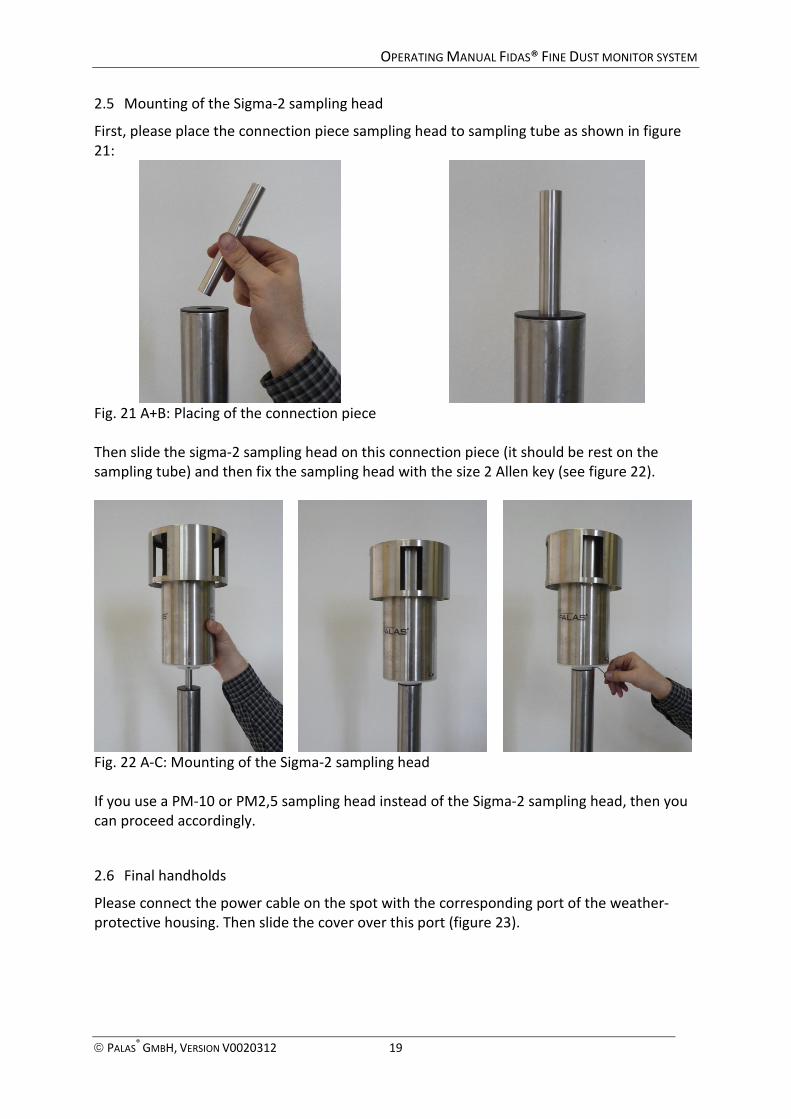
2.5 Mounting of the Sigma-2 sampling head
First, please place the connection piece sampling head to sampling tube as shown in figure
21:
Fig. 21 A+B: Placing of the connection piece
Then slide the sigma-2 sampling head on this connection piece (it should be rest on the
sampling tube) and then fix the sampling head with the size 2 Allen key (see figure 22).
Fig. 22 A-C: Mounting of the Sigma-2 sampling head
If you use a PM-10 or PM2,5 sampling head instead of the Sigma-2 sampling head, then you
can proceed accordingly.
2.6 Final handholds
Please connect the power cable on the spot with the corresponding port of the weather-
protective housing. Then slide the cover over this port (figure 23).
Page 20
OPERATING MANUAL FIDAS® FINE DUST MONITOR SYSTEM
PALAS® GMBH, VERSION V0020312 20
Fig. 23 A+B: Power connection of the weather-protective housing
Then press the power button on the back of Fidas ® control unit.
After booting up the Windows operating system and the Fidas ® start-up manager, you can
see the screen with the various PM fractions, particle number concentration and the
ambient conditions (temperature, relative humidity, atmospheric pressure). For the first
values of the PM fractions you must wait about 4 minutes due to the averaging.
Fig. 24: Fidas® during operation
Page 21
OPERATING MANUAL FIDAS® FINE DUST MONITOR SYSTEM
PALAS® GMBH, VERSION V0020312 21
3 Calibration/ Verification of the Fidas®
A calibration of the instrument should always be performed before the beginning of a
measurement campaign. During an actual measurement campaign, the calibration should be
performed every 6 months.
Before calibration, the instrument must be in operation for at least one hour so that it is in a
thermally stable condition. The ambient temperature must be within 10 and 25°C. To
calibrate, the device has to be in the calibration mode. At the beginning of the calibration
procedure, first the IADS (drying system) is heated up or cooled down to 35 °C so that the
volume flow and the gas dynamics are always the same and the dust that is used for
calibration is conditioned. Usually, you have to wait at least ten minutes. During this
procedure the temperature is displayed and the calibration begins if the user sees that the
temperature is stable at 35°C (+- 0.1°C).
The complete calibration consists of 5 steps:
1.) Automatic offset adjustment
2.) Check of the tightness of the total system
3.) Adjustment of the sensitivity of the particle sensor
4.) Check of the particle flow in the particle sensor
5.) Check of the volume flow
The different steps are described in the following:
3.1 Automatic offset adjustment
The electronical zero point of the system is aligned at the offset adjustment (see figure 26).
Thus, the inherent noise of the instrument is minimized. The offset adjustment is performed
fully automatically and is started via the button „adjust offset“. The adjustment lasts about
two minutes. The minimum of the measured offset voltage must be less than 0.2 mV, the
offset adjustment voltage must be within 2 and 3 V.
3.2 Check of the tightness of the total system
The tightness of the whole system is a precondition for a successful calibration. The Fidas®
200 has a sensor that is directly in front of the pump (see figure 25). To check the tightness
of the whole system, it is sufficient to seal the inlet for example with the thumb. The
measured volume flow must then decrease to 0 l/min (+- 0.1 l/min).
3.3 Adjustment of the sensitivity of the particle sensor
For the adjustment of the sensitivity of the particle sensor, the dust (CalDust 1100 which is
included in the delivery) is applied with particles of a defined size. The particle size
distribution of this dust is monodisperse. The instrument shows the raw data distribution of
the measurement (see figure 26). The peak of this raw data distribution must be in channel
130. This corresponds to a particle size of 0.93 µm. If this is not the case, the voltage of the
photomultiplier has to be changed and the procedure must be repeated then. The voltage
can be changed via the button „calibrate PM amplification“. If the peak is < 130, the voltage
of the photomultiplier must be increased. If the peak is > 130, the voltage of the
photomultiplier must be decreased. Through this adjustment of the photomultiplier voltage
Page 22
OPERATING MANUAL FIDAS® FINE DUST MONITOR SYSTEM
PALAS® GMBH, VERSION V0020312 22
at a particle size, the sensitivity of the measurement device for all particle sizes is
automatically adjusted as the instruments works - unlike other manufacturers of aerosol
spectrometers - with only one A/D converter. Please repeat this procedure until the peak of
the raw data distribution is at 130 (+- 0.5).
3.4 Check of the particle flow in the particle sensor
In addition to the signal amplitude for each individual particle, the sensor also measures the
signal length for each individual particle. This signal length is directly proportional to the
velocity of the particles in the sensor, since the height of the optical measuring volume is
known. If the velocity of the particles in the sensor is not correct, the flow rate in the sensor
is also not correct or the flow guide in the sensor is disturbed. For this reason, the velocity
must be checked; otherwise the concentration is determined incorrectly. If the reason for
the wrong velocity calibration is no leakage, the device must be returned to the
manufacturer. To calibrate the velocity also CalDust 1100 is used since particles of different
sizes show slightly different velocities. By using CalDust 1100, the same particle size is always
used also for the velocity calibration. The lower diagram (see figure 26) in the calibration
mode shows the signal length distribution. Two maxima can be seen.
The left maximum is the length of the signals in the border zone of the sensor (T-aperture),
the right maximum is at the length of the signals through the core zone. If you use the arrow
keys to direct the crosshair in the right maximum, you get the velocity with this signal length
("measured velocity"). This velocity must match the velocity set by the factory (+ - 0.2 m / s).
Due to manufacturing tolerances in the nozzle, the velocities in individual units are slightly
different.
3.5 Check of the volume flow
The volume flow of the instrument must be 4.8 l/min (+- 0.15 l/min) at 23 °C and 1013 hPa.
This can be verified for example with a „Bubble-flow-meter“. If the device is tight (point 2)
and if the velocity of the particle flow in the sensor is correct (point 4), then a check of the
volume flow is not necessary.
Page 23
OPERATING MANUAL FIDAS® FINE DUST MONITOR SYSTEM
PALAS® GMBH, VERSION V0020312 23
Fig. 25: Schematic set-up of the flow of the sampling volume flow
Fig. 26: Screen display during calibration (on the top: raw data distribution of channel 60 to
250 with maximum at 131.53; at the bottom: measured signal length distribution with
accordingly determined velocity – here 9.31 m/s)
Page 24
OPERATING MANUAL FIDAS® FINE DUST MONITOR SYSTEM
PALAS® GMBH, VERSION V0020312 24
Fig. 27: Screen display during automatic offset adjustment
Procedure Size to be calibrated Limits Remark
Automatic offset
adjustment
offset < 0.2 mV fully automated
offset adjustment
voltage
> 2 V; < 3V fully automated
Check of the tightness
of the total system
flow rate < 0.1 l/min by sealing the inlet
Adjustment of the
sensitivity of the
particle sensor
measured peak 130 +- 0.5 with calibration dust
CalDust1100
Check of the particle
flow in the particle
sensor
velocity (CalDust) +- 0.2 m/s of the
factory setting
with calibration dust
CalDust1100 by marking
the right maximum
Check of the volume
flow
4.8 l/min +- 0.15 l/min
referring to 23 °C and
1013 hPa
with gauged volume flow
measurement device
Table1: Calibration procedure
Page 25
OPERATING MANUAL FIDAS® FINE DUST MONITOR SYSTEM
PALAS® GMBH, VERSION V0020312 25
4 Demounting / exchanging the gravimetric filter
To demount the gravimetric filter, the gravimetric filter holder at the bottom side of the
aerosol sensor must be removed.
Fig. 28 A-C: Removing the filter holder
The filter holder (Fig. 28 A) can easily be detached by a downward movement (Fig. 28 B).
Then, the plug connection of the suction tube can be loosened. Therefore, press the plug
connection backwards and at the same time remove the tube with your other hand
(Fig. 28 C).
Now, the filter holder can easily be opened by a counter-clockwise rotation.
Fig. 29 A: Setup of the filter holder
Fig. 29B: Setup of the filter holder
The filter holder consists of an upper and a lower part
which are connected to each other by a screw closure
(see Fig. 29 A and B).
Additionally, on the bottom side, a little fence serves
as support for the gravimetric filter.
Lower part of the filter holder with connection
for the suction tube
Upper part of the filter holder with connection
for the aerosol sensor
Gravimetric filter
Support fence for the gravimetric filter
Page 26
OPERATING MANUAL FIDAS® FINE DUST MONITOR SYSTEM
PALAS® GMBH, VERSION V0020312 26
5 Cleaning the Fidas® System
5.1 How to clean the sensor
5.1.1 For Fidas® 200/200 S and Fidas® 300/300 S Systems
In case of using an aerosol humidity compensation module IADS, firstly, it has to be removed
from the aerosol inlet of the sensor in order to move the control unit with the integrated
sensor sideways.
Fig. 30: Connection of the aerosol inlet with the IADS
5.1.2 For all Fidas® Systems
To clean the internal optical glasses of the aerosol sensor, the filter holder has to be
removed from the sensor outlet. Additionally, the plug connection between the filter holder
and the inlet of the suction pump has to be removed.
Fig. 31 A-C: Removing the filter holder
The filter holder (Fig. 31 A) can now easily be detached by a downward movement (Fig. 31
B). Then, the plug connection of the suction tube can be loosened. Therefore, press the plug
connection backwards and at the same time remove the tube with your other hand
(Fig. 31 C).
IADS
Adapter to connect
the IADS
Move the adapter for the
connection of the IADS to the
aerosol inlet downwards.
Then, the IADS can be completely
moved upwards, so that the aerosol
inlet can easily be accessed.
Page 27
OPERATING MANUAL FIDAS® FINE DUST MONITOR SYSTEM
PALAS® GMBH, VERSION V0020312 27
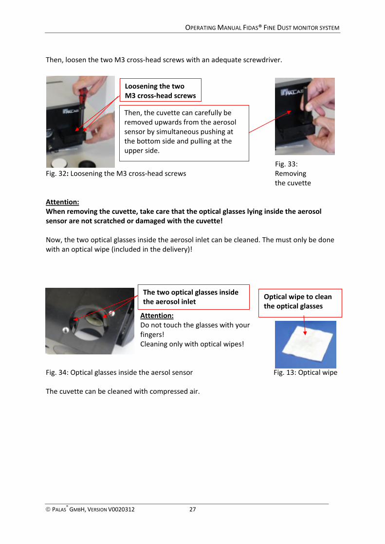
Then, loosen the two M3 cross-head screws with an adequate screwdriver.
Fig. 33:
Fig. 32: Loosening the M3 cross-head screws Removing
the cuvette
Attention:
When removing the cuvette, take care that the optical glasses lying inside the aerosol
sensor are not scratched or damaged with the cuvette!
Now, the two optical glasses inside the aerosol inlet can be cleaned. The must only be done
with an optical wipe (included in the delivery)!
Attention:
Do not touch the glasses with your
fingers!
Cleaning only with optical wipes!
Fig. 34: Optical glasses inside the aersol sensor Fig. 13: Optical wipe
The cuvette can be cleaned with compressed air.
Loosening the two
M3 cross-head screws
The two optical glasses inside
the aerosol inlet
Then, the cuvette can carefully be
removed upwards from the aerosol
sensor by simultaneous pushing at
the bottom side and pulling at the
upper side.
Optical wipe to clean
the optical glasses
Page 28
OPERATING MANUAL FIDAS® FINE DUST MONITOR SYSTEM
PALAS® GMBH, VERSION V0020312 28
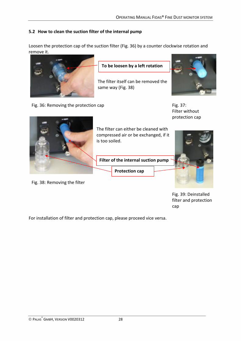
5.2 How to clean the suction filter of the internal pump
Loosen the protection cap of the suction filter (Fig. 36) by a counter clockwise rotation and
remove it.
The filter itself can be removed the
same way (Fig. 38)
Fig. 36: Removing the protection cap Fig. 37:
Filter without
protection cap
The filter can either be cleaned with
compressed air or be exchanged, if it
is too soiled.
Fig. 38: Removing the filter
Fig. 39: Deinstalled
filter and protection
cap
For installation of filter and protection cap, please proceed vice versa.
To be loosen by a left rotation
Protection cap
Filter of the internal suction pump
Page 29
OPERATING MANUAL FIDAS® FINE DUST MONITOR SYSTEM
PALAS® GMBH, VERSION V0020312 29
6 Particle measurement with the Fidas® System
6.1 Special features of the Fidas® system
• Due to white light source and 90° scattered light detection:
- clear calibration curve (also in the so called Mie-range)
• Due to the patented T-aperture technology:
- measurements without border zone error
- automatic coincidence detection and correction according to Dr. Umhauer
and Prof. Dr. Sachweh
• Very high resolution
- high number of measuring channels,
- display of 32 classes per decade ( ≅ 60 classes per measurement range)
• Very high classification accuracy
• Measurement range 0.18 – 18 µm
• Ability to measure even in high concentrations due to
• polychromatic light (LED)
• 90° scattered light detection
• even intensity distribution of light inside the measurement volume
• T-aperture technology
• optically defined measurement volume
• coincidence detection • Sophisticated single particle scattering sensor: max. concentration up to 20.000 P/cm³
Advantage:
The advantage of a counting measurement procedure compared to a collective procedure is
that the particle number and particle size are measured at the same time, but separately.
Page 30
OPERATING MANUAL FIDAS® FINE DUST MONITOR SYSTEM
PALAS® GMBH, VERSION V0020312 30
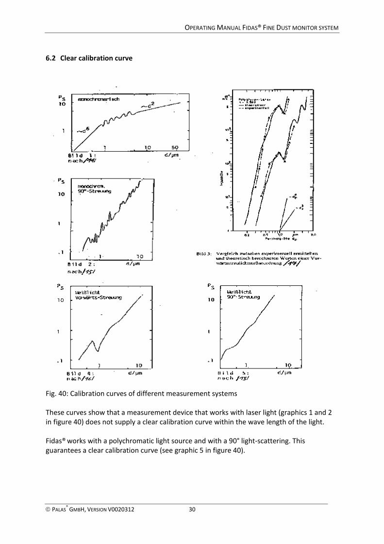
6.2 Clear calibration curve
Fig. 40: Calibration curves of different measurement systems
These curves show that a measurement device that works with laser light (graphics 1 and 2
in figure 40) does not supply a clear calibration curve within the wave length of the light.
Fidas® works with a polychromatic light source and with a 90° light-scattering. This
guarantees a clear calibration curve (see graphic 5 in figure 40).
Page 31
OPERATING MANUAL FIDAS® FINE DUST MONITOR SYSTEM
PALAS® GMBH, VERSION V0020312 31
6.3 High resolution capacity
Fig. 41: Distributions
These curves show that the measurement device can identify a bi-modal distribution in the
range between 0.3 µm and 0.6 µm. This is only possible due to the high-quality resolution
capacity of this device.
6.4 Basic definitions in measurement technology
Classification accuracy
How exact is the measurement of the testing aerosol? Does the determined particle size
distribution meet the actual particle size distribution of the testing aerosol?
Resolution capacity
How exact is the resolution of the device? Does the optical particle counter even determine
the difference between very close particle sizes?
Ambiguity
Does the optical particle counter determine unambiguously the particle sizes within the
range of wave length of the laser light?
There even 180° white light forward scattering delivers ambiguous results.
Border zone error
Does the device consider the tolerances in the border zones caused by the Gaussian
distribution of laser light?
Page 32
OPERATING MANUAL FIDAS® FINE DUST MONITOR SYSTEM
PALAS® GMBH, VERSION V0020312 32
Counting efficiency
How many particles of the testing aerosol are really measured at a known concentration?
Coincidence error
How do you assure that the light impulse is caused by only one particle?
6.5 Effects of the device’s characteristics
Border Zone Error
The particle size spectrum is measured with too many fines. The broader the particle size
spectrum is measured, the more important becomes the border zone error.
Coincidence Error
The particle size spectrum is measured too coarse, the particle concentration is measured
too small. According to the definition, a coincidence of 10% is tolerable.
Counting Efficiency
The lower counting efficiency results in a shifting of the particle size distribution towards
coarse particles because the fines are undervalued. The upper counting efficiency similarly
undervalues the coarse particles. The quantity is determined incorrectly. When measuring
with several particle counters, the counting efficiency difference between the used counters
has to be known. Only then, the results are comparable!
Classification Accuracy
During correlation measurements (e.g. with impactors), the correlation factor becomes
better, the higher is the classification precision.
Instruments with a good classification precision over the total measurement range supply
reliable distributions.
Resolution Capacity
During correlation measurements (e.g. with impactors), the correlation factor becomes
better, the higher is the resolution capacity. Instruments with a high resolution capacity are
able to measure bi- and tri-modal distributions that are located close to each other.
Page 33
OPERATING MANUAL FIDAS® FINE DUST MONITOR SYSTEM
PALAS® GMBH, VERSION V0020312 33
7 Ensuring correct measurement conditions
In case of disadvantageous test conditions, the measuring result, i.e. the determined particle
size distribution of the single measurements, can considerably differ from the actual existing
values in the aerosol flow.
Therefore, please pay attention to:
• Representative sample taking
• Isokinetic sampling
• Minimal particle losses through the aerosol transport
• No coincidence error
Please note: Palas® regularly offers training courses about these topics.
As a basic principle, the Fidas® System can only measure and display data it has been
registred in its optical measuring volume. That means, the aerosol sampling flow should be
lead there as straight as possible.
Therefore, please pay attention to:
- short tubes for the aerosol
- if possible, metal tubes, in no case longer plastic tubes (high particle separation due to
electrostatic charging)
- vertical aerosol guiding, as bigger particles (> 5 µm) sediment respectively the aerosol
seperates
As basic principle of all counting scattered light measuring technologies, just one single
particle may be in the optically limited measuring volume of the sensor at the same time.
This due to the fact, that the scattered light of the single particle is being evaluated for the
determination of the particle size.
If more than one particles are in the measuring volume at the same time, these particles are
measured as one, i.e. the particle is being measured too big and the number to small.
To measure correctly, one has to dilute. The Palas® dilution systems have proven themselves
in practice at the market. If requested, they can be heated and be used in overpressure and
underpressure.
If a measurement has been done correctly with a dilution, this measurement supplies a finer
particle size distribution and a higher particle concentration as result, compared to a
measurement in coincidence. A separation efficiency that was measured in coincidence is
always worse compared to one being measured under correct conditions.
The advices given here are surely not sufficient to ensure a correct measurement in any
case. In case of particular problems, please contact Palas® directly.
Page 34
OPERATING MANUAL FIDAS® FINE DUST MONITOR SYSTEM
PALAS® GMBH, VERSION V0020312 34
8 Technical data Fidas® System:
Size of optical measuring volume
(WxDxH) approx. 262 µm x 262 µm x 164 µm*
Maximum concentration for
10 % coincidence error
Sensor integrated into the control unit
max.concentration up to 4 x 10³ P/cm³
Communication between control
unit and evaluation PC USB or Modbus
Suction volume flow Standard value, depending on the model
Cleaning
The housings can be cleaned with non-aggressive
detergents (e.g. household detergent) or spirit.
For cleaning of the optical lenses, see
correspondent chapter in operation manual.
Mains connections
(see identification plate!)
mains voltage:
mains fuse:
230 V, +/-10%
2 pieces T 2 A / 250 V
115 V, +/-10%
2 pieces T 4 A / 130 V
Power consumption
frequency
200 W
47-63 Hz
Environmental conditions Temperature range from 0 °C to 40 °C
Sound emission << 85 dBA
Dimensions (HxWxD)
Control unit incl. integrated sensor:
195 mm x 450 mm x 310 mm
Weather protective housing with IADS and
weather station:
1810 mm x 600 mm x 400 mm
Weight Control unit incl. integrated sensor:
10 kg
Weather protective housing with IADS, Sigma-2
and weather station:
48 kg
Technical data are subject to change.
* The real size of the measuring volume is indicated in the software.
Page 35
OPERATING MANUAL FIDAS® FINE DUST MONITOR SYSTEM
PALAS® GMBH, VERSION V0020312 35
9 Annexes:
9.1 IP-65 weather-protective housing for Fidas® System:
Fig. 42: Weather-protective housing closed Fig. 43: Weather-protective housing open
Weather-protective
housing
Aerosol humidity
compensation module IADS
Sigma-2 sampling head
Weather station
WS600-UMB
GPS receiver
Fidas® control unit
with integrated
aerosol sensor
Electronics of the
GPS receiver
Electric manifold
Page 36
OPERATING MANUAL FIDAS® FINE DUST MONITOR SYSTEM
PALAS® GMBH, VERSION V0020312 36
9.2 Aerosol humidity compensation module IADS
With high ambient humidity, water condensates onto the particles and thus falsifies the
particle size. This effect can be avoided by use of the aerosol humidity compensation module
IADS.
The aerosol humidity compensation module IADS is connected with an adapter to the
aerosol sensor of the Fidas® system. For cleaning of the aerosol sensor, the adapter is
pushed downwards, so that the IADS can be pushed upwards completely. Then, the aerosol
inlet of the sensor is easy to access.
The aerosol humidity compensation module is controlled via the Fidas® Firmware (see
separate manual Fidas® Firmware for detailed information).
Fig. 44: Sigma-2 sampling head with IADS
Fig. 45: Fidas® control unit, aerosol sensor with IADS
Mouting of the IADS
IADS
Aerosol sensor
Sigma-2 sampling head
IADS
Page 37
OPERATING MANUAL FIDAS® FINE DUST MONITOR SYSTEM
PALAS® GMBH, VERSION V0020312 37
9.3 Sigma-2 sampling head
The Sigma-2 sampling head according to VDI 2119-4 for measurements widely independent
of winds is simply put on the aerosol inlet of the Fidas® sensor or, if there
is one, on the aerosol humidity compensation module IADS.
Using a hexagon socket screw key, it can be fixed by the locking screw.
Fig. 46: Sigma-2 sampling head
9.4 Compact weather station WS600-UMB
Fig. 47: Compact weather station WS600-UMB
The weather station WS600-UMB is readout by the Fidas® Firmware (see separate manual
Fidas® Firmware for detailed information).
Special features:
• All in One
• Aspirated temperature/humidity measurement
• Maintenance-free operation
• Open communication protocol
Sigma-2 sampling head
Compact weather station
WS600-UMB
For measurement of:
• wind speed
• wind direction
• precipitation quantity
• type of precipitation
• temperature
• humidity
• pressure
Mounting of the WS600-UMB at the IP65 weather-protective housing
IP65 weather-protective housing
Locking screw
Page 38
OPERATING MANUAL FIDAS® FINE DUST MONITOR SYSTEM
PALAS® GMBH, VERSION V0020312 38
Description country version: EU, USA and Canada:
WS600-UMB compact weather station for air temperature, relative humidity, precipitation
intensity, precipitation type, precipitation quantity, air pressure, wind direction and wind
speed. Relative humidity is measured by means of a capacitive sensor element; a precision
NTC measuring element is used to measure air temperature. Precipitation is measured by
way of a 24 GHz Doppler radar, which measures the drop speed of an individual drop of
rain/snow. Precipitation quantity and intensity are calculated from the correlation between
drop size and speed. The difference in drop speed determines the type of precipitation
(rain/snow). Maintenance-free measurement offers a major advantage over the common
tipping spoon and tipping bucket processes. Ultrasound sensor technology is used to take
wind measurements. Measurement data are available for further processing in the form of a
standard protocol (Lufft-UMB protocol).
Page 39
OPERATING MANUAL FIDAS® FINE DUST MONITOR SYSTEM
PALAS® GMBH, VERSION V0020312 39
9.4.1 Technical data WS600-UMB
Dimensions Ø ca. 150mm, height ca. 345mm
Weight ca. 2,2kg
Interface RS485, 2-wire, half-duplex
Power supply 24 VDC ± 10 % <4 VA (without heating)
Operating temperature -50...60 °C
Operating rel. humidity 0...100 % r.H.
Heating 40 VA at 24 VDC
Cable length 10 m
Sensor for temperature:
Principle NTC
Measuring range -50 .. 60 °C
Unit °C
Accuracy ± 0,2 °C (-20...50 °C), otherwise ± 0,5 °C (> -30 °C)
Sensor for relative humidity:
Principle capacitive
Measuring range 0 .. 100 % r.H.
Unit % r.H.
Accuracy ± 2 % r.H.
Sensor for air pressure:
Principle MEMS capacitive
Measuring range 300 .. 1200 hPa
Unit hPa
Accuracy ± 1.5 hPa
Sensor for wind direction:
Principle Ultrasonic
Measuring range 0 .. 359.9 °
Unit °
Accuracy ± 3 °
Sensor for wind speed:
Principle Ultrasonic
Measuring range 0 .. 60 m/s
Unit m/s
Accuracy ± 0,3 m/s or 3 % (0...35 m/s)
Sensor for precipitation amount:
Resolution 0.01 mm
Reproducibility Typical > 90 %
Measuring range drop size 0,3...5mm
Type of precipitation Rain/snow
Accessories of the WS600-UMB compact weather station:
UMB Interface converter ISOCON
Mast 4.5m, hot-dip galvanized, tiltable
Power supply 24V/4A
Page 40
OPERATING MANUAL FIDAS® FINE DUST MONITOR SYSTEM
PALAS® GMBH, VERSION V0020312 40
10 Reader’s comments sheet
In order to improve our manuals continuously we kindly ask you to fill in this questionnaire and to
return it to Palas®. Thank you for your cooperation.
How to contact us:
Address: Greschbachstraße 3 b, 76229 Karlsruhe, Germany
Phone: +49 721 96213-0 Fax: +49 721 96213-33 E-mail: [email protected]
This evaluation concerns: Fidas fine dust monitor systems, V0020312
Please inform us about your contact data:
Company: ______________________________________________________________________
Name: _________________________________________________________________________
Address: ________________________________________________________________________
Telephone or e-mail: ______________________________________________________________
Were the procedures clearly written and easy to understand?
� yes � no
If not, please explain: _____________________________________________________________
_______________________________________________________________________________
Did you miss some information?
� yes � no
If yes, please explain: _____________________________________________________________
_______________________________________________________________________________
Have you been satisfied with the structure of the manual? Did you quickly find the required
information?
� yes � no
If not, please explain: _____________________________________________________________
_______________________________________________________________________________
In case of technical problems, have you been satisfied with the telephone support?
� yes � no
If not, please explain: _____________________________________________________________
_______________________________________________________________________________
Please feel free to add any comments you may find necessary or helpful:
_______________________________________________________________________________
_______________________________________________________________________________
_______________________________________________________________________________
_______________________________________________________________________________
_______________________________________________________________________________