English ® Chapters 1. General warnings and safety specifications pag. 3 2. Definition of available models pag. 4 3. Installation pag. 7 4. Operating the machine and preparing coffee pag. 9 5. Preparing other hot drinks pag. 12 6. Maintenance and weekly cleaning operations pag. 13 7. De-commissioning and demolition pag.14 8. History and use of the La Marzocco coffee machines pag. 15 Operating Manual Operating Manual MODEL. “LINEA” - “FB 70” / VERSION. “EE” - “AV” Via Bolognese 68 Pian Di San Bartolo 50010 Firenze, Italy t: +39. 055.401.390 f: +39.055.401.349 e-mail: marzocco @ webitaly.com - www.lamarzocco.com La Marzocco s.r.l.
Transcript
En
gli
sh
®
C h a p t e r s
1. General warnings and safety specifications pag. 3
2. Definition of available models pag. 4
3. Installation pag. 7
4. Operating the machine and preparing coffee pag. 9
5. Preparing other hot drinks pag. 12
6. Maintenance and weekly cleaning operations pag. 13
7. De-commissioning and demolition pag.14
8. History and use of the La Marzoccocoffee machines pag. 15
O p e r a t i n g M a n u a lO p e r a t i n g M a n u a lMODEL. “LINEA” - “FB 70” / VERSION. “EE” - “AV”
Via Bolognese 68 Pian Di San Bartolo 50010 Firenze, Italy
1) This operating manual is an integral and essen-tial part of the product and must be supplied tousers. Users are asked to read the enclosed warningscarefully, as they provide valuable information con-cerning safety during installation, operation andmaintenance.This manual must be kept in a safe place and be avail-able for consultation to new and experienced usersalike.
2) Make sure of the product’s integrity by inspectingthe packaging, making sure it presents no signs of dam-age which might have affected the enclosed machine.
3) Check the machine’s integrity after having careful-ly removed the packaging.Notes 2 and 3:in case of doubt, do not go on any further and contactyour dealer or retailer immediately. They will send outspecialized personnel authorized to do work on themachine.
4) Packaging (boxes, plastic bags, foam parts andwhatever else) must not be left around within easy reachof children, due to the potential danger it represents, norbe discarded in the environment.
5) Check to see that data on the rating plate corre-spond to those of the mains electrical supply which themachine will be hooked up to.
The installation must be done according to currentregulations and to the manufacturer’s instructions, andmust be performed by qualified and authorized person-nel.
Incorrect installation may be cause for injury/dam-ages to people, animals or objects, for which the manu-facturer shall not be held responsible.
Safe electrical operation of this device will beachieved only when the connection to the power outlethas been completed correctly and in observance of cur-rent safety regulations, and particularly by grounding theunit very carefully. Make sure grounding has been donecorrectly as it represents a fundamental safety require-ment and, in case of doubt, do not hesitate to have qual-ified personnel check such connection.
Furthermore, you must ensure that the capacity ofthe available electrical system is suitable for the maxi-mum power consumption indicated on the rating plate;make sure also that electrical cables are of a suitable size.
We do not recommend using adapters, multipleplugs and/or extension cords. If you cannot avoid usingthem, make sure that they are exclusively of the kindwhich conforms to current safety regulations, beingcareful not to exceed the power and current ratings indi-cated on such adapters and extension cords.
6) This device must be used exclusively for the func-tions it has been designed and built for. Any other appli-cation is inappropriate and dangerous. The manufac-turer shall not be held responsible for any damagescaused by improper and irrational use.
7) Using any electrical device requires that certainfundamental rules be observed.In particular:- do not touch the device while having wet or humid
hands and feet;- do not use the device while having no shoes on yourfeet;- do not use extension cords in bath or shower rooms;- do not unplug the device from the power outlet bypulling on the power supply cable;- do not expose the device to atmospheric agents (rain,sun, etc.);- do not allow children or untrained people to use thisdevice;- do not clean the control panel with a wet cloth since itis not watertight.
8) Before carrying out any maintenance and/or clean-ing operations, turn the main switch, which is located onthe machine, to the “0” position, and disconnect themachine from the electrical network by unplugging thecord or by switching off the relative circuit breaker. Forany cleaning operation, follow exclusively the instruc-tions contained in this manual.
9) In case the machine is operating in a faulty man-ner or breaks down, disconnect it from the electrical net-work (as described in the preceding point) and close thewater supply tap. Do not attempt to repair it, and con-tact qualified and authorized professionals. Any repairsmust be performed exclusively by the manufacturer orby an authorized centre using only original parts. Noncompliance with the above forfeits the warranty andcould compromise the safe operation of the machine.
10) You should plan to make use of an omnipolarconnector during installation, as required by currentsafety regulations, complete with fuses suitable to bearthe power of the machine being connected.
11) In order to avoid dangerous overheating prob-lems, it is recommended that the power supply cable befully unfurled.
12) Do not obstruct air intake and exhaust grilles and,in particular, do not cover the cup warmer tray withcloths or other items.
13) The machine’s power supply cable must not bereplaced by users, as also specified on the rating platelocated near the outlet of such cable, on the body. Incase the cable gets damaged, shut off the machine (asdescribed in point 8) and close off the water supply; toreplace it, contact qualified professionals exclusively.
CAUTION:As already mentioned in the preceding notes, themanufacturer shall not be held responsible for dam-ages to objects, animals and/or people whenever themachine has not been installed according to theinstructions contained in this manual, and is not usedto do what it was designed for (i.e. preparing coffeeand hot drinks).
3
En
gli
sh
1. General Warnings and Safety Specifications
This operating manual refers exclusively to the followingmodels, of our own manufacture:
Mod. EE - Mod. AV with 1, 2, 3 e 4 groups
Everything set out in this operating manual is also validfor the “FB70” series. The only differences are the exter-nal dimension of the machine.
4
En
glish
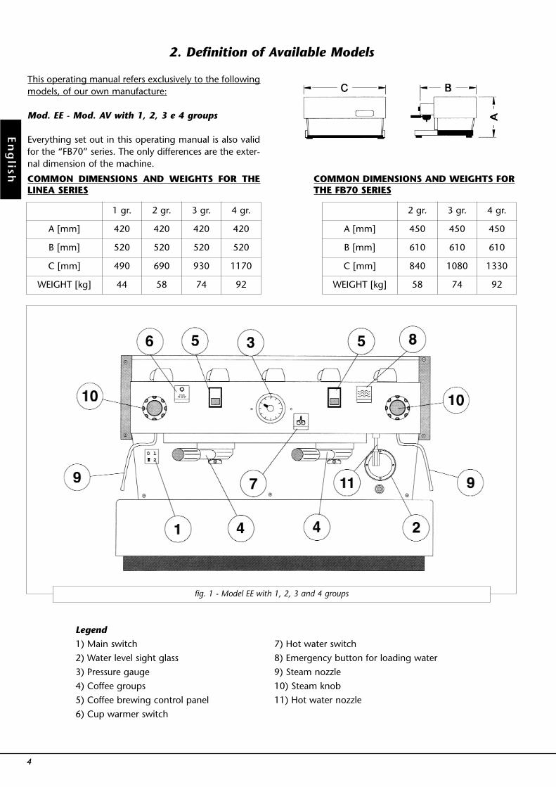
2. Definition of Available Models
fig. 1 - Model EE with 1, 2, 3 and 4 groups
Legend
1) Main switch
2) Water level sight glass
3) Pressure gauge
4) Coffee groups
5) Coffee brewing control panel
6) Cup warmer switch
7) Hot water switch
8) Emergency button for loading water
9) Steam nozzle
10) Steam knob
11) Hot water nozzle
COMMON DIMENSIONS AND WEIGHTS FOR THELINEA SERIES
A [mm]
B [mm]
C [mm]
WEIGHT [kg]
420
520
490
44
420
520
690
58
420
520
930
74
420
1 gr. 2 gr. 3 gr. 4 gr.
520
1170
92
COMMON DIMENSIONS AND WEIGHTS FORTHE FB70 SERIES
A [mm]
B [mm]
C [mm]
WEIGHT [kg]
450
610
840
58
450
610
1080
74
450
610
1330
92
2 gr. 3 gr. 4 gr.
General descriptionThe model EE machine is built in the 1, 2, 3, and 4 groupversions and is essentially composed of the followingparts:
1. Water boiler (produces steam and hot water);2. Coffee (“saturation”) boiler;3. Brewing groups;4. Cover;5. Motor pump;6. Water purifier.
Description of the various parts
1. Water BoilerIt consists of a cylindrical tank, of varying length accord-ing to the number of coffee groups, which is made of Aisi304 stainless steel. Each unit is subjected to a hydraulictest, at a pressure of 3 bar, and has an operating pressureof 1.5 bar. In the following, you will find a list of effectivevolumes and power ratings according to the number ofgroups installed:
1 group 3,5 litres 1300 Watts2 groups 7 litres 2000 Watts3 groups 11 litres 3000 Watts4 groups 15 litres 3800 Watts
Covers are installed at either end of the cylindrical tankand on one of them there is a housing for the water heat-ing and vapourizing electrical elements, which allowreaching operating pressure within 25’ approximately.Operating pressure is maintained by a manostat. Thewater boiler has various fittings used for safety devices,for supplying hot water and steam, and for the powersupply.
2. Coffee BoilerEach unit is subjected to a hydraulic test, at a pressure of16 bar, and has an operating pressure of 9 bar. In the fol-lowing, you will find a list of effective volumes and powerratings according to the number of groups installed:
1 group 1.8 litres 1000 Watts2 groups 3.4 litres 1400 Watts3 groups 5.0 litres 1600 Watts4 groups 3.4 + 3.4 litres 1400 + 1400 Watts
(2 boilers installed)
It consists of a cylindrical tank, of varying length accord-ing to the number of coffee groups, which is made of Aisi304 stainless steel.
Covers are installed at either end of the cylindrical tankand on one of them there is a housing for the water heat-ing and vapourizing electrical elements, regulated by aprecision thermostat with a dT of ± 1°C wich keeps thewater temperature constant. This temperature can beadjusted to reach optimal temperature according to thetype of coffee blend being used. The groups are installedon the boiler.
3. Brewing GroupsThey consist of a die-cast block made of nickel-platedbrass, on which to install the filter-holder handle used tohold the ground coffee; the espresso flows from theblock, through a spout, into the cup(s) after the brewingbutton has been pressed.
4. CoverIt consists of a painted and stainless sheet steel body. Thestructure has been the object of specific studies to pro-vide good aesthetics, to lower ergonometric costs for theoperator and to reduce the chance of damage to a min-imum.
5. Motor PumpThe pump, which is of the “positive-displacement” type,is installed on the water supply tubing and is set-up tooperate anytime the coffee groups are activated, andthrough an electric level gauge whenever the water boil-er needs to be replenished.
6. Water PurifierIt is of the “ion exchange” resin type, for water softeningpurposes. Resins must be regenerated weekly accordingto the instructions and the diagrams shown on the labelsaffixed to the purifiers themselves. See Chapter 6.
5
En
gli
sh
En
glish
6
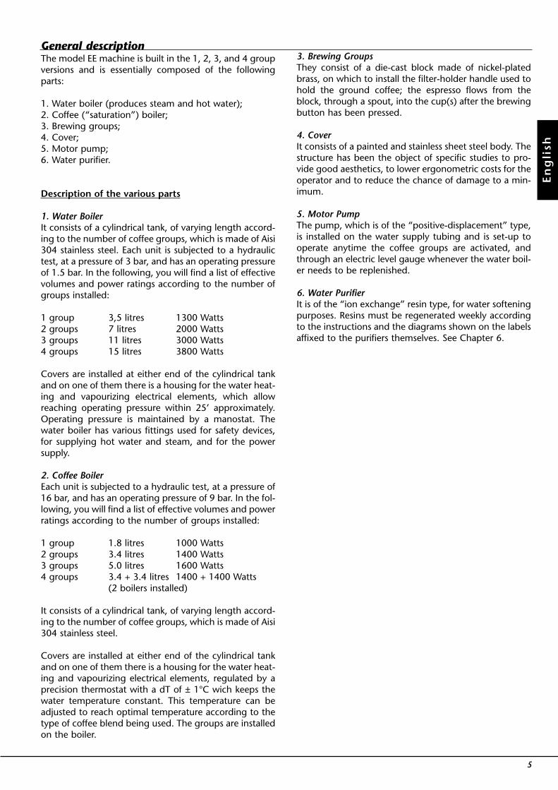
fig. 2 - MODEL AV with 1, 2, 3 and 4 groups
Legend1. Main switch2. Water level sight glass3. Pressure gauge4. Coffee groups5. Coffee dispensing control panel6. Cup warmer switch7. Hot water switch8. Emergency button for loading water9. Steam nozzle10. Steam knob11. Hot water nozzle12. Key operated switch to enable dosage programming
Not available in Version 3D513. Manual brew switch
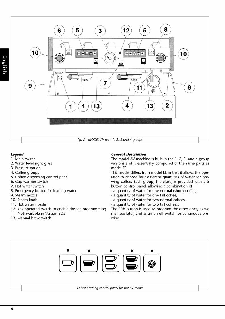
General DescriptionThe model AV machine is built in the 1, 2, 3, and 4 groupversions and is essentially composed of the same parts asmodel EE.This model differs from model EE in that it allows the ope-rator to choose four different quantities of water for bre-wing coffee. Each group, therefore, is provided with a 5button control panel, allowing a combination of:- a quantity of water for one normal (short) coffee;- a quantity of water for one tall coffee;- a quantity of water for two normal coffees;- a quantity of water for two tall coffees.The fifth button is used to program the other ones, as weshall see later, and as an on-off switch for continuous bre-wing.
Coffee brewing control panel for the AV model
En
gli
sh
7
Legend
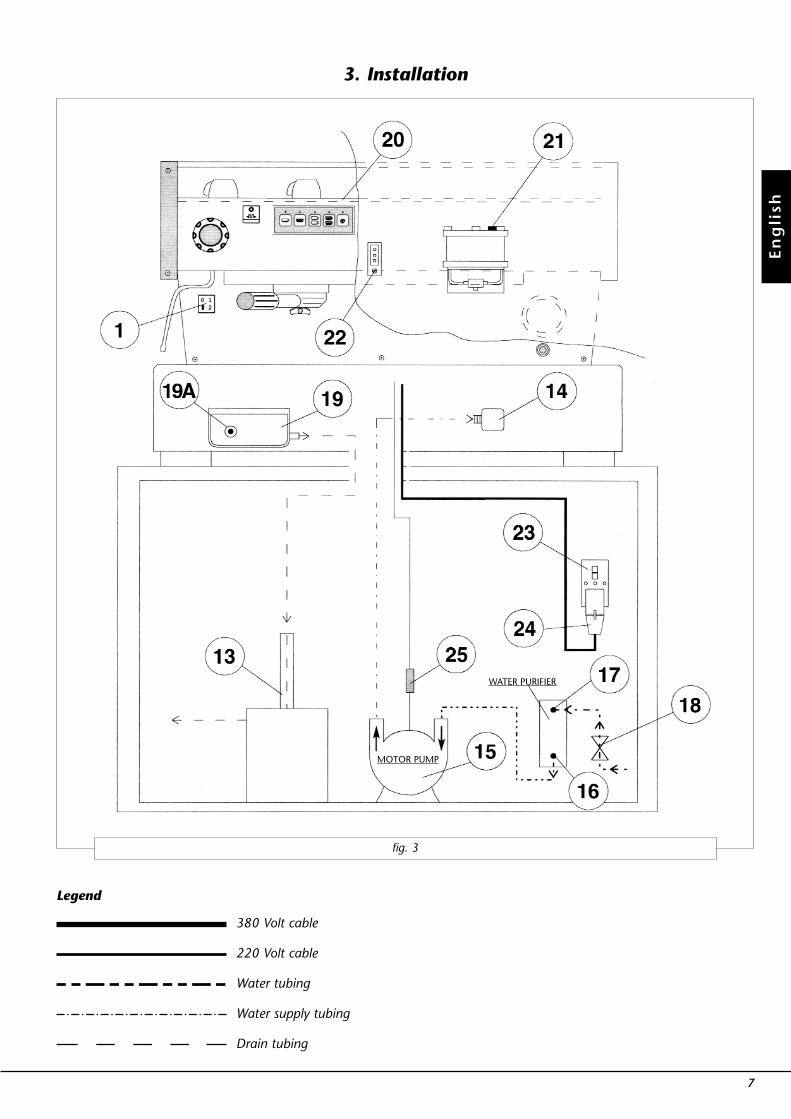
fig. 3
3. Installation
380 Volt cable
220 Volt cable
Water tubing
Water supply tubing
Drain tubing
MOTOR PUMP
WATER PURIFIER
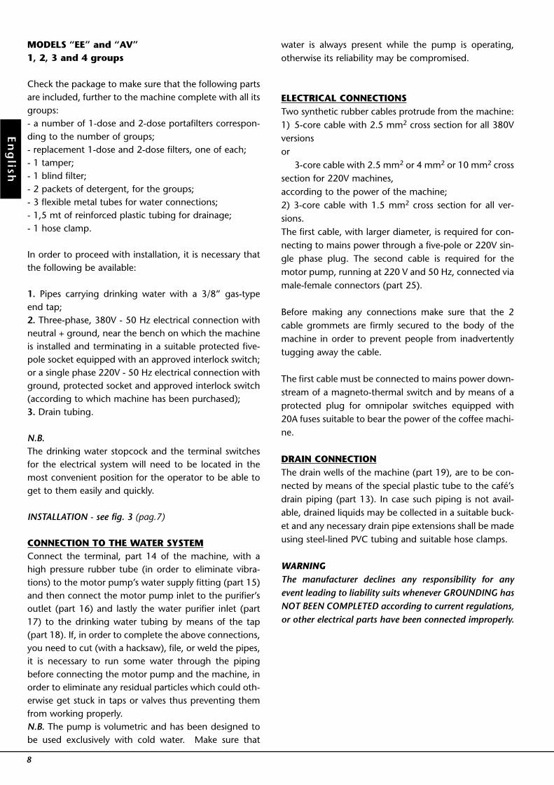
MODELS “EE” and “AV”1, 2, 3 and 4 groups
Check the package to make sure that the following partsare included, further to the machine complete with all itsgroups:- a number of 1-dose and 2-dose portafilters correspon-ding to the number of groups;- replacement 1-dose and 2-dose filters, one of each;- 1 tamper;- 1 blind filter;- 2 packets of detergent, for the groups;- 3 flexible metal tubes for water connections;- 1,5 mt of reinforced plastic tubing for drainage;- 1 hose clamp.
In order to proceed with installation, it is necessary thatthe following be available:
1. Pipes carrying drinking water with a 3/8” gas-typeend tap;2. Three-phase, 380V - 50 Hz electrical connection withneutral + ground, near the bench on which the machineis installed and terminating in a suitable protected five-pole socket equipped with an approved interlock switch;or a single phase 220V - 50 Hz electrical connection withground, protected socket and approved interlock switch(according to which machine has been purchased);3. Drain tubing.
N.B.The drinking water stopcock and the terminal switchesfor the electrical system will need to be located in themost convenient position for the operator to be able toget to them easily and quickly.
INSTALLATION - see fig. 3 (pag.7)
CONNECTION TO THE WATER SYSTEMConnect the terminal, part 14 of the machine, with ahigh pressure rubber tube (in order to eliminate vibra-tions) to the motor pump’s water supply fitting (part 15)and then connect the motor pump inlet to the purifier’soutlet (part 16) and lastly the water purifier inlet (part17) to the drinking water tubing by means of the tap(part 18). If, in order to complete the above connections,you need to cut (with a hacksaw), file, or weld the pipes,it is necessary to run some water through the pipingbefore connecting the motor pump and the machine, inorder to eliminate any residual particles which could oth-erwise get stuck in taps or valves thus preventing themfrom working properly.N.B. The pump is volumetric and has been designed tobe used exclusively with cold water. Make sure that
water is always present while the pump is operating,otherwise its reliability may be compromised.
ELECTRICAL CONNECTIONSTwo synthetic rubber cables protrude from the machine:1) 5-core cable with 2.5 mm2 cross section for all 380Vversionsor
3-core cable with 2.5 mm2 or 4 mm2 or 10 mm2 crosssection for 220V machines,according to the power of the machine;2) 3-core cable with 1.5 mm2 cross section for all ver-sions.The first cable, with larger diameter, is required for con-necting to mains power through a five-pole or 220V sin-gle phase plug. The second cable is required for themotor pump, running at 220 V and 50 Hz, connected viamale-female connectors (part 25).
Before making any connections make sure that the 2cable grommets are firmly secured to the body of themachine in order to prevent people from inadvertentlytugging away the cable.
The first cable must be connected to mains power down-stream of a magneto-thermal switch and by means of aprotected plug for omnipolar switches equipped with20A fuses suitable to bear the power of the coffee machi-ne.
DRAIN CONNECTIONThe drain wells of the machine (part 19), are to be con-nected by means of the special plastic tube to the café’sdrain piping (part 13). In case such piping is not avail-able, drained liquids may be collected in a suitable buck-et and any necessary drain pipe extensions shall be madeusing steel-lined PVC tubing and suitable hose clamps.
WARNINGThe manufacturer declines any responsibility for anyevent leading to liability suits whenever GROUNDING hasNOT BEEN COMPLETED according to current regulations,or other electrical parts have been connected improperly.
8
En
glish
Once installation has been completed, you can proceedto hook up the filter holders (Fig. 4), together with theirfilters, to the bottom of the groups by rotating themfrom left to right; before operating the various switchesand thus powering up the heater elements, fill up theboiler tanks with water, as follows:1. COFFEE BOILERThe water flows inside the coffee boiler directly, as soonas the water system and purifier taps are opened. Sincethe inflowing water will compress the air in the boiler, itwill be necessary, in order to completely “saturate” theboiler-groups assembly, to remove the group cover plate(part 20 Fig. 3) and unscrew the small bolt (part 21) a lit-tle way so as to allow air to escape until a few drops ofwater leak out, at which point you should repeat suchoperation for each group and then tighten the smallbolts again and reinstall the cover plate.2) WATER BOILERBy turning the main switch (part 1) to position “1”, theautomatic level gauge will be switched on which, byactivating the solenoid valve and the motor pump (part15), will fill the water boiler up to a predetermined levelselected by adjusting the probe inside the boiler itself.
N.B.It may happen that the air inside the boiler builds uppressure (which may be detected through the pressuregauge - part 3, Fig 1 or 2) when the water is allowed toflow in; this “false” pressure must be eliminated by open-ing the vapourizing tap (part 10, Fig. 1 or 2).Once you have completed these operations, turn themain switch (part 1) to position “2” and wait for the boil-ers to reach operating temperature and pressure (whichtakes from 20 to 35 minutes, depending on the type ofmachine), which will be subsequently maintained at aconstant value automatically.During this time, it may happen that the pointer of thelower scale on the pressure gauge (part 3, Fig. 1 or 2)reach as high as 14-15 bar; this may occur any time that,while activating the groups, the motor pump forces coldwater into the coffee boiler at a pressure of 8-9 bar and,simultaneously, the thermostat regulating the tempera-ture of the boiler itself switches on the heating elements
in order to bring the water contained in such boiler upto operating temperature. However, in this case it is nec-essary to adjust the 19A expansion valve (Fig. 3) in sucha way that the pressure may never exceed 11 bar.
For model EE - fig. 1Once you have ensured that the filter holders (Fig. 4) areproperly tightened, you should press the brewing but-tons (part 5) 2 or 3 times and hold them pressed a fewseconds each time, in order to pre-heat the holders. Youmay then remove the one that you want to make coffeewith (1 or 2 cups), together with its own filter, and pro-ceed to place some ground coffee in the filter itself: 1dose (approximately 6 g) for the small filter, 2 doses (2coffees) for the larger filter. Press down on the groundcoffee with the supplied tamper and hook the filter hold-er up again to the bottom of the group and then pressthe switch (part 5) thus allowing coffee to be brewed;
when you have obtained the right amount of coffee,press the switch again (part 5), at which point themachine discharges the pressure built up in the filterholder. The holder may then be removed to proceedwith making the next cup of coffee, if so desired.
CAUTION:Do not remove the filter holder when its relative group isbrewing hot liquids. Such action may be cause for severeburns.
9
En
gli
sh
4. Operating the Machine and Preparing Coffee
fig. 4 - Filter Holder (see part. 4, fig. 1 or 2)
COFFEE BREWING BUTTON (part 5)
FILTER HOLDER
FILTER
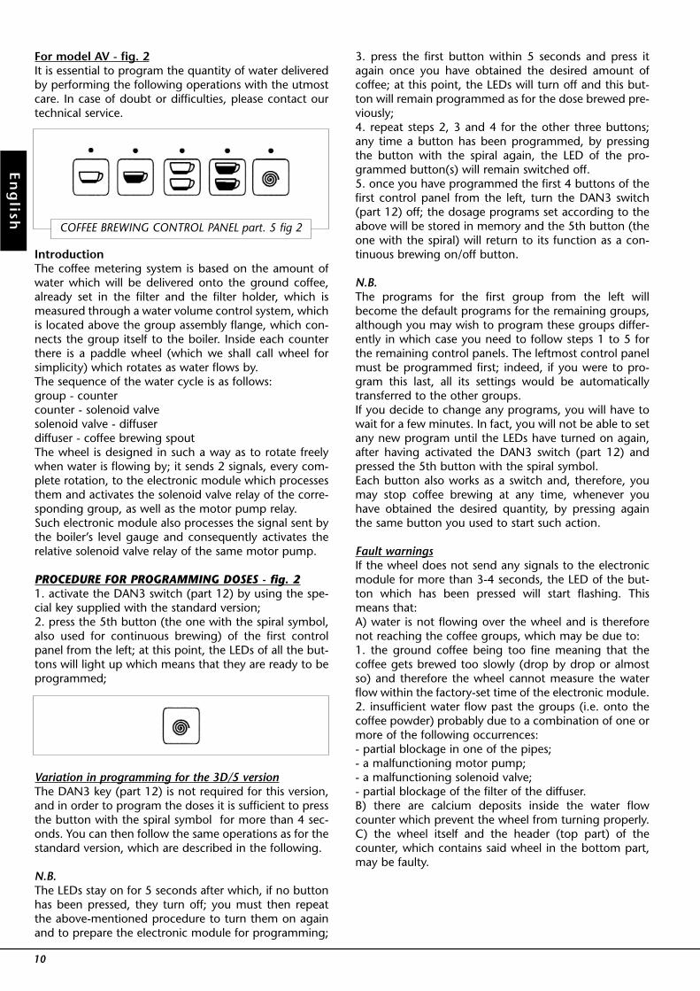
For model AV - fig. 2It is essential to program the quantity of water deliveredby performing the following operations with the utmostcare. In case of doubt or difficulties, please contact ourtechnical service.
IntroductionThe coffee metering system is based on the amount ofwater which will be delivered onto the ground coffee,already set in the filter and the filter holder, which ismeasured through a water volume control system, whichis located above the group assembly flange, which con-nects the group itself to the boiler. Inside each counterthere is a paddle wheel (which we shall call wheel forsimplicity) which rotates as water flows by.The sequence of the water cycle is as follows:group - countercounter - solenoid valvesolenoid valve - diffuserdiffuser - coffee brewing spoutThe wheel is designed in such a way as to rotate freelywhen water is flowing by; it sends 2 signals, every com-plete rotation, to the electronic module which processesthem and activates the solenoid valve relay of the corre-sponding group, as well as the motor pump relay.Such electronic module also processes the signal sent bythe boiler’s level gauge and consequently activates therelative solenoid valve relay of the same motor pump.
PROCEDURE FOR PROGRAMMING DOSES - fig. 21. activate the DAN3 switch (part 12) by using the spe-cial key supplied with the standard version;2. press the 5th button (the one with the spiral symbol,also used for continuous brewing) of the first controlpanel from the left; at this point, the LEDs of all the but-tons will light up which means that they are ready to beprogrammed;
Variation in programming for the 3D/5 versionThe DAN3 key (part 12) is not required for this version,and in order to program the doses it is sufficient to pressthe button with the spiral symbol for more than 4 sec-onds. You can then follow the same operations as for thestandard version, which are described in the following.
N.B.The LEDs stay on for 5 seconds after which, if no buttonhas been pressed, they turn off; you must then repeatthe above-mentioned procedure to turn them on againand to prepare the electronic module for programming;
3. press the first button within 5 seconds and press itagain once you have obtained the desired amount ofcoffee; at this point, the LEDs will turn off and this but-ton will remain programmed as for the dose brewed pre-viously;4. repeat steps 2, 3 and 4 for the other three buttons;any time a button has been programmed, by pressingthe button with the spiral again, the LED of the pro-grammed button(s) will remain switched off.5. once you have programmed the first 4 buttons of thefirst control panel from the left, turn the DAN3 switch(part 12) off; the dosage programs set according to theabove will be stored in memory and the 5th button (theone with the spiral) will return to its function as a con-tinuous brewing on/off button.
N.B.The programs for the first group from the left willbecome the default programs for the remaining groups,although you may wish to program these groups differ-ently in which case you need to follow steps 1 to 5 forthe remaining control panels. The leftmost control panelmust be programmed first; indeed, if you were to pro-gram this last, all its settings would be automaticallytransferred to the other groups.If you decide to change any programs, you will have towait for a few minutes. In fact, you will not be able to setany new program until the LEDs have turned on again,after having activated the DAN3 switch (part 12) andpressed the 5th button with the spiral symbol.Each button also works as a switch and, therefore, youmay stop coffee brewing at any time, whenever youhave obtained the desired quantity, by pressing againthe same button you used to start such action.
Fault warningsIf the wheel does not send any signals to the electronicmodule for more than 3-4 seconds, the LED of the but-ton which has been pressed will start flashing. Thismeans that:A) water is not flowing over the wheel and is thereforenot reaching the coffee groups, which may be due to:1. the ground coffee being too fine meaning that thecoffee gets brewed too slowly (drop by drop or almostso) and therefore the wheel cannot measure the waterflow within the factory-set time of the electronic module.2. insufficient water flow past the groups (i.e. onto thecoffee powder) probably due to a combination of one ormore of the following occurrences:- partial blockage in one of the pipes;- a malfunctioning motor pump;- a malfunctioning solenoid valve;- partial blockage of the filter of the diffuser.B) there are calcium deposits inside the water flowcounter which prevent the wheel from turning properly.C) the wheel itself and the header (top part) of thecounter, which contains said wheel in the bottom part,may be faulty.
10
En
glish
COFFEE BREWING CONTROL PANEL part. 5 fig 2
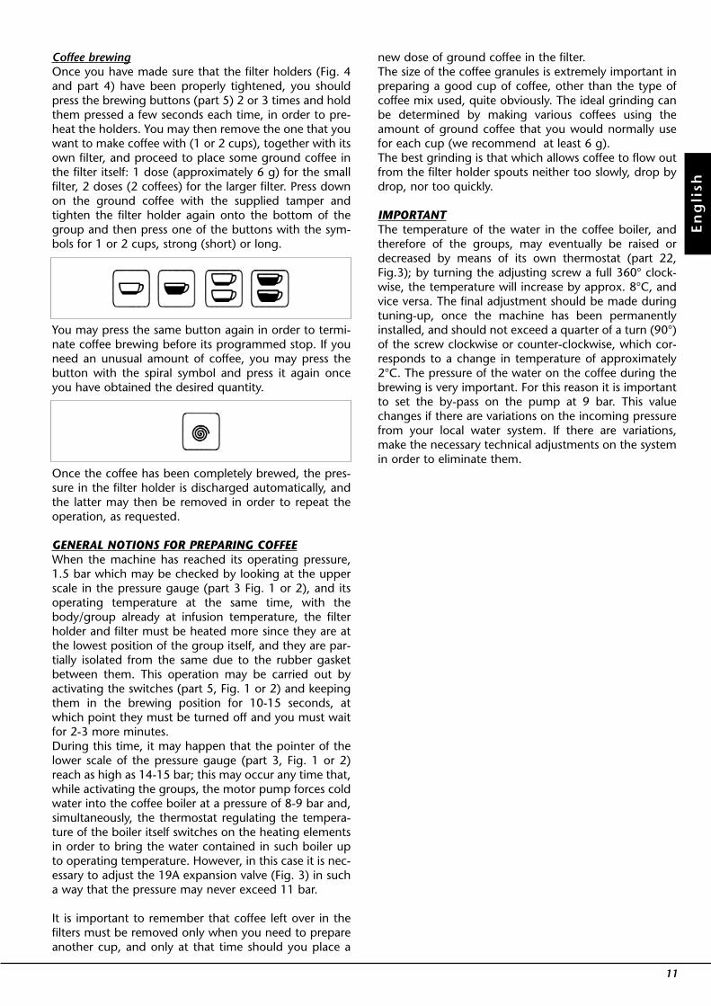
Coffee brewingOnce you have made sure that the filter holders (Fig. 4and part 4) have been properly tightened, you shouldpress the brewing buttons (part 5) 2 or 3 times and holdthem pressed a few seconds each time, in order to pre-heat the holders. You may then remove the one that youwant to make coffee with (1 or 2 cups), together with itsown filter, and proceed to place some ground coffee inthe filter itself: 1 dose (approximately 6 g) for the smallfilter, 2 doses (2 coffees) for the larger filter. Press downon the ground coffee with the supplied tamper andtighten the filter holder again onto the bottom of thegroup and then press one of the buttons with the sym-bols for 1 or 2 cups, strong (short) or long.
You may press the same button again in order to termi-nate coffee brewing before its programmed stop. If youneed an unusual amount of coffee, you may press thebutton with the spiral symbol and press it again onceyou have obtained the desired quantity.
Once the coffee has been completely brewed, the pres-sure in the filter holder is discharged automatically, andthe latter may then be removed in order to repeat theoperation, as requested.
GENERAL NOTIONS FOR PREPARING COFFEEWhen the machine has reached its operating pressure,1.5 bar which may be checked by looking at the upperscale in the pressure gauge (part 3 Fig. 1 or 2), and itsoperating temperature at the same time, with thebody/group already at infusion temperature, the filterholder and filter must be heated more since they are atthe lowest position of the group itself, and they are par-tially isolated from the same due to the rubber gasketbetween them. This operation may be carried out byactivating the switches (part 5, Fig. 1 or 2) and keepingthem in the brewing position for 10-15 seconds, atwhich point they must be turned off and you must waitfor 2-3 more minutes.During this time, it may happen that the pointer of thelower scale of the pressure gauge (part 3, Fig. 1 or 2)reach as high as 14-15 bar; this may occur any time that,while activating the groups, the motor pump forces coldwater into the coffee boiler at a pressure of 8-9 bar and,simultaneously, the thermostat regulating the tempera-ture of the boiler itself switches on the heating elementsin order to bring the water contained in such boiler upto operating temperature. However, in this case it is nec-essary to adjust the 19A expansion valve (Fig. 3) in sucha way that the pressure may never exceed 11 bar.
It is important to remember that coffee left over in thefilters must be removed only when you need to prepareanother cup, and only at that time should you place a
new dose of ground coffee in the filter.The size of the coffee granules is extremely important inpreparing a good cup of coffee, other than the type ofcoffee mix used, quite obviously. The ideal grinding canbe determined by making various coffees using theamount of ground coffee that you would normally usefor each cup (we recommend at least 6 g).The best grinding is that which allows coffee to flow outfrom the filter holder spouts neither too slowly, drop bydrop, nor too quickly.
IMPORTANTThe temperature of the water in the coffee boiler, andtherefore of the groups, may eventually be raised ordecreased by means of its own thermostat (part 22,Fig.3); by turning the adjusting screw a full 360° clock-wise, the temperature will increase by approx. 8°C, andvice versa. The final adjustment should be made duringtuning-up, once the machine has been permanentlyinstalled, and should not exceed a quarter of a turn (90°)of the screw clockwise or counter-clockwise, which cor-responds to a change in temperature of approximately2°C. The pressure of the water on the coffee during thebrewing is very important. For this reason it is importantto set the by-pass on the pump at 9 bar. This valuechanges if there are variations on the incoming pressurefrom your local water system. If there are variations,make the necessary technical adjustments on the systemin order to eliminate them.
11
En
gli
sh
En
glish
12
HOT DRINKS
Dip one of the 2 nozzles (part 9, Fig. 1 or 2) which areconnected to the steam tap, into the liquid to be heat-ed, turn the knob (part 10, Fig. 1 or 2) gradually untilsteam comes out at the end of the nozzle (1).The steam will transfer heat to the liquid raising its tem-perature up to boiling point.Be careful not to allow liquid to overflow in order toavoid severe burns.In order to prepare milk for making cappuccino with theright amount of foam, go through the following steps:- Place the container half-full of milk under the steamnozzle, open the tap and bring the temperature of themilk almost up to boiling point.- Lower the container so as to bring the nozzle end to apoint just below the surface of the milk; at this point,move the container up and down just enough to dip thenozzle end in and out of the milk until you get the rightamount of foam.You can then pour this milk into a cup containing warmespresso and you will end up with a fresh cup of cap-puccino.
PREPARING TEA - CHAMOMILEAND OTHER DRINKS
You can get hot water by using the fixed nozzle (part 11),located between the group furthest to the right and the steamnozzle (part 9), and pressing the button (part 7, Fig. 1 or 2)
which commands hot water delivery; you can then addthe bag containing tea, chamomile, etc. The purifiedwater delivered by the nozzle will usually make the drinkdarker in colour.If you wish to have a drink with a lighter colour, just takesome cold water from an ordinary water tap and heat itup by using the steam nozzle (part 9) and then add thetea bag or other bag.
5. Preparing other hot drinks
N.B.
In order to prevent part of the liquid to be heated from being sucked back into the boiler (due to a possible tempo-rary decompression inside the boiler tank) which would cause, after a few days, both the steam and the liquid deliv-ered by nozzle part 9 and nozzle part 11 respectively to smell bad, we recommend that you de-vapourize the machineonce or twice for just a few seconds, which consists of quickly opening and closing the tap (part 10) with the nozzle(part 9) not dipped in the liquid before starting such operation.Furthermore, once you have immersed the steam wand into the liquid to be steamed in the pitcher, open the steamtap immediately. Once the liquid has been heated, follow this procedure:- lower the steam pressure- remove the pitcher- close the steam tap
En
gli
sh
13
The machine must not be dipped in, nor splashedwith, water in order to clean it. For cleaning opera-tions, please follow the instructions listed below verycarefully.
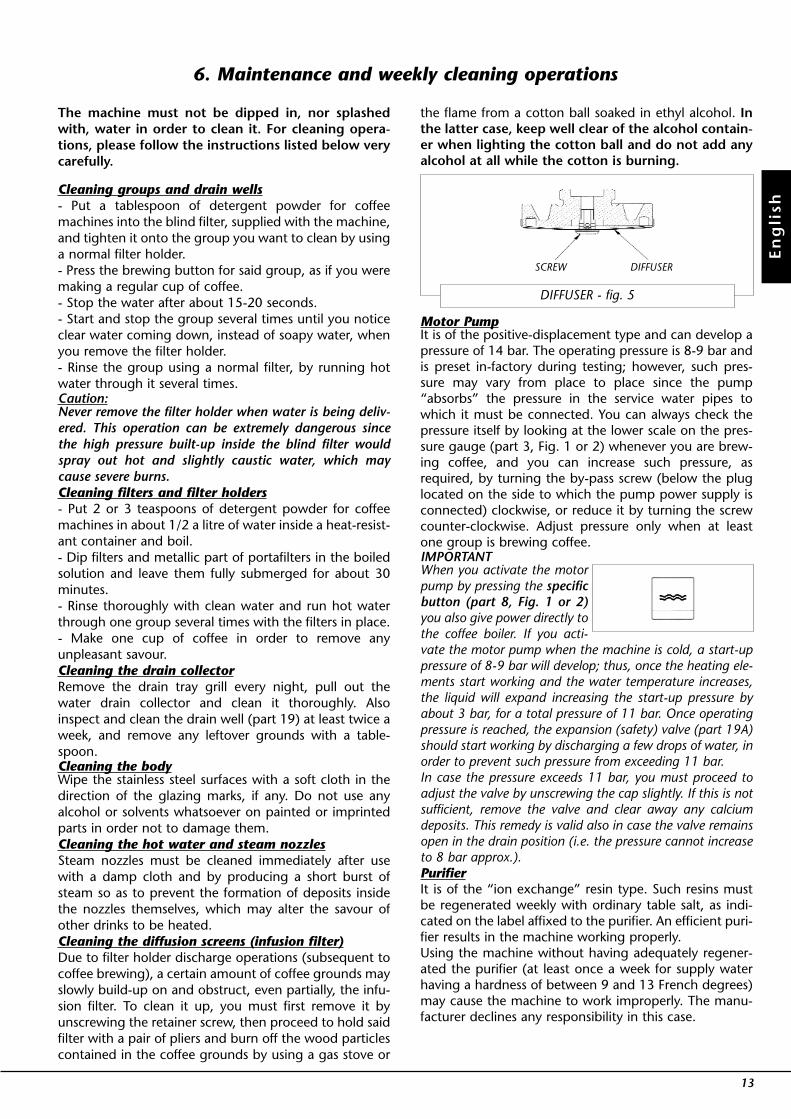
Cleaning groups and drain wells- Put a tablespoon of detergent powder for coffeemachines into the blind filter, supplied with the machine,and tighten it onto the group you want to clean by usinga normal filter holder.- Press the brewing button for said group, as if you weremaking a regular cup of coffee.- Stop the water after about 15-20 seconds.- Start and stop the group several times until you noticeclear water coming down, instead of soapy water, whenyou remove the filter holder.- Rinse the group using a normal filter, by running hotwater through it several times.Caution:Never remove the filter holder when water is being deliv-ered. This operation can be extremely dangerous sincethe high pressure built-up inside the blind filter wouldspray out hot and slightly caustic water, which maycause severe burns.Cleaning filters and filter holders- Put 2 or 3 teaspoons of detergent powder for coffeemachines in about 1/2 a litre of water inside a heat-resist-ant container and boil.- Dip filters and metallic part of portafilters in the boiledsolution and leave them fully submerged for about 30minutes.- Rinse thoroughly with clean water and run hot waterthrough one group several times with the filters in place.- Make one cup of coffee in order to remove anyunpleasant savour.Cleaning the drain collectorRemove the drain tray grill every night, pull out thewater drain collector and clean it thoroughly. Alsoinspect and clean the drain well (part 19) at least twice aweek, and remove any leftover grounds with a table-spoon.Cleaning the bodyWipe the stainless steel surfaces with a soft cloth in thedirection of the glazing marks, if any. Do not use anyalcohol or solvents whatsoever on painted or imprintedparts in order not to damage them.Cleaning the hot water and steam nozzlesSteam nozzles must be cleaned immediately after usewith a damp cloth and by producing a short burst ofsteam so as to prevent the formation of deposits insidethe nozzles themselves, which may alter the savour ofother drinks to be heated.Cleaning the diffusion screens (infusion filter)Due to filter holder discharge operations (subsequent tocoffee brewing), a certain amount of coffee grounds mayslowly build-up on and obstruct, even partially, the infu-sion filter. To clean it up, you must first remove it byunscrewing the retainer screw, then proceed to hold saidfilter with a pair of pliers and burn off the wood particlescontained in the coffee grounds by using a gas stove or
the flame from a cotton ball soaked in ethyl alcohol. Inthe latter case, keep well clear of the alcohol contain-er when lighting the cotton ball and do not add anyalcohol at all while the cotton is burning.
Motor PumpIt is of the positive-displacement type and can develop apressure of 14 bar. The operating pressure is 8-9 bar andis preset in-factory during testing; however, such pres-sure may vary from place to place since the pump“absorbs” the pressure in the service water pipes towhich it must be connected. You can always check thepressure itself by looking at the lower scale on the pres-sure gauge (part 3, Fig. 1 or 2) whenever you are brew-ing coffee, and you can increase such pressure, asrequired, by turning the by-pass screw (below the pluglocated on the side to which the pump power supply isconnected) clockwise, or reduce it by turning the screwcounter-clockwise. Adjust pressure only when at leastone group is brewing coffee.IMPORTANTWhen you activate the motorpump by pressing the specificbutton (part 8, Fig. 1 or 2)you also give power directly tothe coffee boiler. If you acti-vate the motor pump when the machine is cold, a start-uppressure of 8-9 bar will develop; thus, once the heating ele-ments start working and the water temperature increases,the liquid will expand increasing the start-up pressure byabout 3 bar, for a total pressure of 11 bar. Once operatingpressure is reached, the expansion (safety) valve (part 19A)should start working by discharging a few drops of water, inorder to prevent such pressure from exceeding 11 bar.In case the pressure exceeds 11 bar, you must proceed toadjust the valve by unscrewing the cap slightly. If this is notsufficient, remove the valve and clear away any calciumdeposits. This remedy is valid also in case the valve remainsopen in the drain position (i.e. the pressure cannot increaseto 8 bar approx.).PurifierIt is of the “ion exchange” resin type. Such resins mustbe regenerated weekly with ordinary table salt, as indi-cated on the label affixed to the purifier. An efficient puri-fier results in the machine working properly.Using the machine without having adequately regener-ated the purifier (at least once a week for supply waterhaving a hardness of between 9 and 13 French degrees)may cause the machine to work improperly. The manu-facturer declines any responsibility in this case.
6. Maintenance and weekly cleaning operations
DIFFUSER - fig. 5
SCREW DIFFUSER
MOTOR PUMP
WATER PURIFIER
En
glish
14
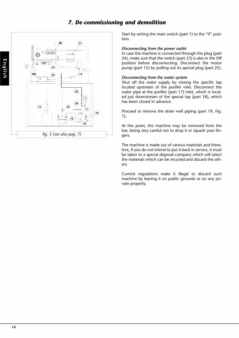
Start by setting the main switch (part 1) to the “0” posi-tion.
Disconnecting from the power outletIn case the machine is connected through the plug (part24), make sure that the switch (part 23) is also in the Offposition before disconnecting. Disconnect the motorpump (part 15) by pulling out its special plug (part 25).
Disconnecting from the water systemShut off the water supply by closing the specific taplocated upstream of the purifier inlet. Disconnect thewater pipe at the purifier (part 17) inlet, which is locat-ed just downstream of the special tap (part 18), whichhas been closed in advance.
Proceed to remove the drain well piping (part 19, Fig.1).
At this point, the machine may be removed from thebar, being very careful not to drop it or squash your fin-gers.
The machine is made out of various materials and there-fore, if you do not intend to put it back in service, it mustbe taken to a special disposal company which will selectthe materials which can be recycled and discard the oth-ers.
Current regulations make it illegal to discard suchmachine by leaving it on public grounds or on any pri-vate property.
7. De-commissioning and demolition
fig. 3 (see also pag. 7)
La Marzocco has been producing espresso coffeemachines for use in cafés since 1927.In February of 1939, when machines being manufactu-red were exclusively of the vertical boiler type, “LaMarzocco” designed and built the first horizontal boilermachines, for which it obtained a “patent”.Second World War brought an end to production of cof-fee machines, and it prevented the Bambi brothers frommaintaining the patent obtained and therefore, at theend of the war, all the coffee machine producers beganmanufacturing again and they adopted the “horizontal”boiler, which was more practical and suitable for newdemands and which is still in use now.Throughout time, various machines have been designedand built: of the type operating on “Water/Steam” andon the principle of “Hydrocompression”, and of the leveroperated, air and steam type; semi-automatic and auto-matic, with mechanical and electrical actuators, up untilcurrent production which consists of machines allowingcontinuous “brewing” operation.
CHARACTERISTICS PARTICULARTO THE LA MARZOCCO MACHINESThe great majority of the espresso coffee machines beingbuilt today, of almost any brand, are of the “continuousbrewing” type, whose basic concept is to use the samewater in the tubing, directly to brew coffee by increasingits pressure mechanically and heating it in advance.In any case, a good cup of coffee is the result of 4 highlyinterdependent components, to such extent that if onlyone of them is not quite in perfect harmony with theothers, the resulting cup of coffee will turn out not quiteas pleasant in taste.
1) Coffee MixIndependently of the various qualities of coffee thatmake it up, the type of toasting, etc., the freshness of thecoffee beans and the way they are preserved is veryimportant.For coffee beans to be used on espresso machines, it’s agood rule of thumb to wait at least 8-10 days after toa-sting, so that the beans may re-absorb part of the humi-dity they lost during the toasting process itself, and touse coffee beans within 3-4 days of opening their con-tainer.
2) WaterWithin the limits imposed by the type supplied locally,water should be free of bad savours and “softened”using a suitable water softener in order to avoid calciumbuild-up; in any case, hardness should not exceed 9°F. Ifwater tastes like chlorine it is recommended that you usean active carbon filter.
3) Coffee GrinderIt must allow you to grind coffee beans in a wide varietyof granule sizes, in the most uniform manner possibleand, once you have established the amount of groundcoffee required for each cup, the grinder must guaranteea constant amount from dose to dose. It is best to grindcoffee from time to time, trying not to leave any groundcoffee in the grinder overnight and during days off.
4) Espresso machineAmong other things, the espresso machine must gua-rantee the following qualities:A) the most appropriate water temperature for the typeof coffee mix used, constant in time so as to ensure thata good cup of coffee may be prepared any time, whetheryou have to make several, one after the other, or onefrom time to time.B) a constant water pressure through the brewing groupand the coffee mix.As far as the “B quality” is concerned, it is usually obtai-ned by means of the same system in all the “continuousbrewing” type machines, that is by using a positive-dis-placement motor pump, while “quality A” can be obtai-ned with various systems. The great majority of manufacturers uses systems whichare very similar to one another. The underlying principleis to heat up the water used for brewing coffee, whichcomes directly from the pipes and is pushed by themotor pump, by running it through coils or cartridges(small containers) which are located in the boiler. It fol-lows that the latter must be quite large, which entails anoticeable power consumption, and the temperaturemay be controlled exclusively through a manostat, adevice which is specifically designed for controlling pres-sure and not temperature; indeed, the temperaturechanges every time the water/steam ratio in the boilerchanges, and even more so when the latter is replenis-hed with cold water.It is quite obvious that the coils or cartridges whichsupply water to the brewing groups are very sensitive tothe above changes. Furthermore, the heat exchange bet-ween the main boiler and the coil varies greatly when, astime goes on, conduction of heat is reduced due to cal-cium deposits forming on the inside and outside of coilsor cartridges. In light of the above, and to avoid wasta-ge of electric energy required to keep large quantities ofwater at operating temperature/pressure, when only asmall part is utilized, our machines have been designedwith 2 small boilers, of the size which is most suited tothe kind of services they have to offer. One of them, a “STEAM GENERATOR”, is used to deliversteam and hot water for various drinks while the other, a“HOT WATER GENERATOR”, is used for the coffee. Thelatter, therefore, produces hot water used exclusively forbrewing coffee, which will flow out, every time the spe-cific group is activated, thanks to the force of the coldwater (actually produced by the positive-displacementpump). The temperature of such water is controlled by aTHERMOSTAT-like device which is extremely sensitiveand has a differential of ±1° C, adjustable to 1/10 of a
15
En
gli
sh
8. History and use of the “La Marzocco” Coffee Machines
degree in order to adapt it to the optimal temperature,depending on the type of coffee mix being used.The brewing groups, cast in brass and weighing 3 Kgeach approximately, work like thermal “flywheels”. Theyare connected directly to the boiler by means of a largemanifold and are thus an integral part of the boiler itself.The manifold is shaped in such a way that each group islocated at a greater height than the boiler, so that, justlike in the elements of a thermosiphon, a natural circula-tion of hot water takes place within each group, at thesame temperature of the boiler and kept constant by thethermostatic system described previously. The use ofthese small boilers, completely independent from oneanother, the special manifold and fastening system of thegroups to the boiler as well as the “thermostatic” tem-perature control, have allowed us to:1) achieve an excellent thermal equilibrium between thebrewing groups, both at times of discontinuous opera-tion and during peak times;2) be able to control the temperature of the water run-ning through the brewing groups, independently of the“pressure” and the level in the small steam boiler, andtherefore to optimize the water temperature itself inorder to obtain the best possible coffee with whatevercoffee mixes are available commercially;3) save on electrical energy by more than 30%, in manycases, when compared to other machines.The “LINEA” series machines are produced in the 1, 2, 3and 4 group versions, the model “EE” having continuousbrewing operation and the “AV” model positive-displa-cement automatic brewing.
CONTROL SYSTEMS AND SAFETY DEVICES BUILT INTO“LA MARZOCCO” COFFEE MACHINESAll models are equipped with:- automatic level regulator;- automatic pressure regulator;- automatic temperature regulator;- safety devices
Spring operated safety valve;Manual thermostats.
In both models, coffee is brewed by opening a solenoidvalve, one for each group. For the “EE” model, the quan-tity of coffee brewed is regulated manually by the ope-rator through a switch, while in the “AV” model thequantity is regulated automatically in 4 different doses,which may be programmed at will for each brewinggroup. This last model is equipped with control panels,one located above each group, with 4 buttons whichmay be programmed in such a way that by pressing the1st button you get 1 regular coffee, pressing the 2nd oneyou get one tall coffee, pressing the 3rd you get 2 regu-lar coffees and by pressing the 4th one you get 2 tall cof-fees. The fifth button, which has a spiral sign, allows con-tinuous brewing operation which can be interrupted bypressing the very same button again.
CONSTRUCTION DETAILSThey consist essentially of 2 small boilers, of which:1. “C.C.” hot water generator for brewing coffee.2. “C.V.” steam generator for producing steam and hotwater for making tea and other hot drinks.
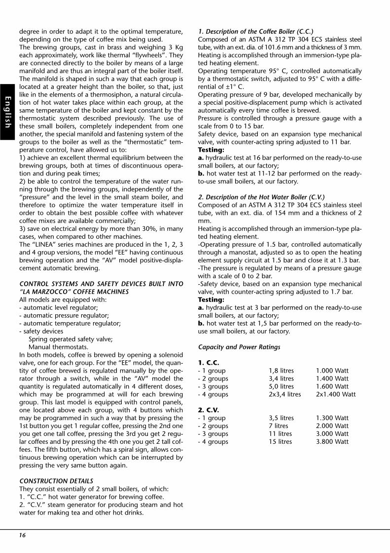
1. Description of the Coffee Boiler (C.C.)Composed of an ASTM A 312 TP 304 ECS stainless steeltube, with an ext. dia. of 101.6 mm and a thickness of 3 mm.Heating is accomplished through an immersion-type pla-ted heating element.Operating temperature 95° C, controlled automaticallyby a thermostatic switch, adjusted to 95° C with a diffe-rential of ±1° C.Operating pressure of 9 bar, developed mechanically bya special positive-displacement pump which is activatedautomatically every time coffee is brewed.Pressure is controlled through a pressure gauge with ascale from 0 to 15 bar.Safety device, based on an expansion type mechanicalvalve, with counter-acting spring adjusted to 11 bar.Testing:a. hydraulic test at 16 bar performed on the ready-to-usesmall boilers, at our factory;b. hot water test at 11-12 bar performed on the ready-to-use small boilers, at our factory.
2. Description of the Hot Water Boiler (C.V.)Composed of an ASTM A 312 TP 304 ECS stainless steeltube, with an ext. dia. of 154 mm and a thickness of 2mm.Heating is accomplished through an immersion-type pla-ted heating element.-Operating pressure of 1.5 bar, controlled automaticallythrough a manostat, adjusted so as to open the heatingelement supply circuit at 1.5 bar and close it at 1.3 bar.-The pressure is regulated by means of a pressure gaugewith a scale of 0 to 2 bar.-Safety device, based on an expansion type mechanicalvalve, with counter-acting spring adjusted to 1.7 bar.Testing:a. hydraulic test at 3 bar performed on the ready-to-usesmall boilers, at our factory;b. hot water test at 1,5 bar performed on the ready-to-use small boilers, at our factory.
Capacity and Power Ratings
1. C.C.- 1 group 1,8 litres 1.000 Watt- 2 groups 3,4 litres 1.400 Watt- 3 groups 5,0 litres 1.600 Watt- 4 groups 2x3,4 litres 2x1.400 Watt
2. C.V.- 1 group 3,5 litres 1.300 Watt- 2 groups 7 litres 2.000 Watt- 3 groups 11 litres 3.000 Watt- 4 groups 15 litres 3.800 Watt
16
En
glish
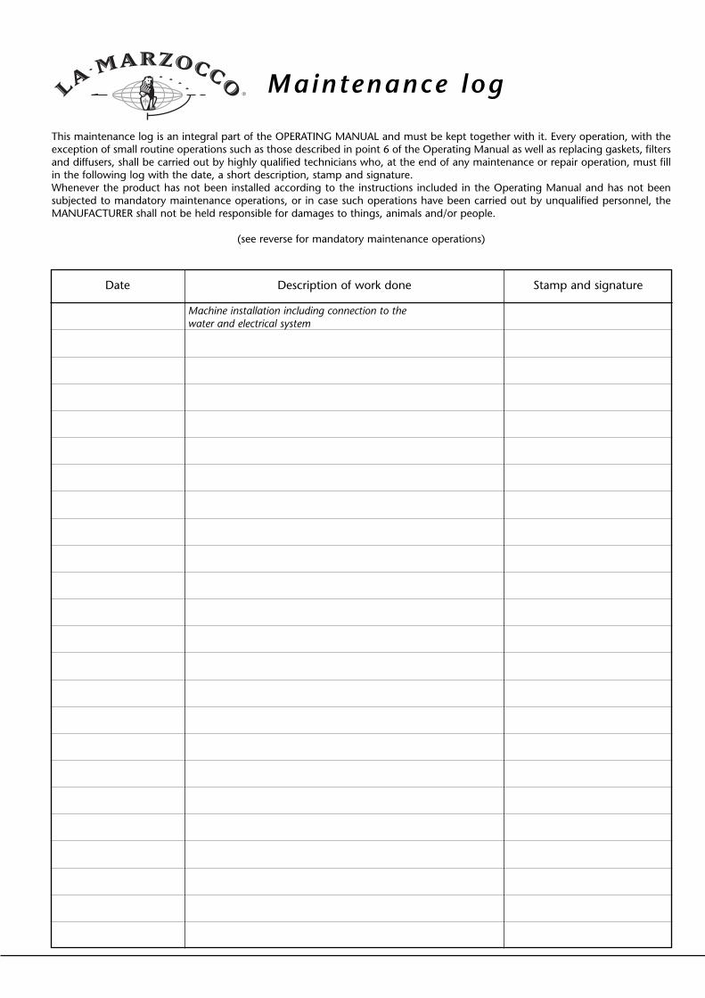
®Maintenance log
This maintenance log is an integral part of the OPERATING MANUAL and must be kept together with it. Every operation, with theexception of small routine operations such as those described in point 6 of the Operating Manual as well as replacing gaskets, filtersand diffusers, shall be carried out by highly qualified technicians who, at the end of any maintenance or repair operation, must fillin the following log with the date, a short description, stamp and signature.Whenever the product has not been installed according to the instructions included in the Operating Manual and has not beensubjected to mandatory maintenance operations, or in case such operations have been carried out by unqualified personnel, theMANUFACTURER shall not be held responsible for damages to things, animals and/or people.
(see reverse for mandatory maintenance operations)
Date Description of work done Stamp and signature
Machine installation including connection to thewater and electrical system
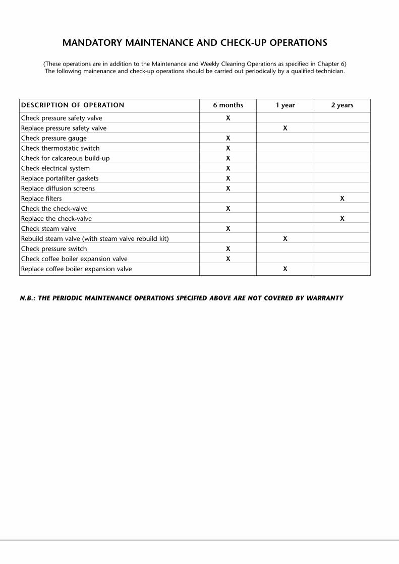
(These operations are in addition to the Maintenance and Weekly Cleaning Operations as specified in Chapter 6)The following mainenance and check-up operations should be carried out periodically by a qualified technician.
DESCRIPTION OF OPERATION 6 months
X
XXXXXX
X
X
XX
X
X
X
X
X
1 year 2 years
N.B.: THE PERIODIC MAINTENANCE OPERATIONS SPECIFIED ABOVE ARE NOT COVERED BY WARRANTY