33
| Date post: | 20-Apr-2018 |
| Category: |
Documents |
| Upload: | nguyenphuc |
| View: | 216 times |
| Download: | 2 times |


1.1. Tables of
Contents 1.1. Tables of Contents..…………………………………………………
1.2. Getting Started…………………………………….…………………
1.3. Product Overview..……………………………….…………………
1.4. Product Specifications..………………………….…………………
1.5. Parts and Functions………..…………………….…………………
1.6. Operating………………………………………….…………………
1.7. Warning………………………………………………………………
1.8. Trouble Shooting…… ………………………………………………
1.2. Getting Thank you very much for purchasing OYO
Started GC Series Programmable Growth Chamber.
Your Growth Chamber has been designed with function, reliability, and
safety in mind. It is your responsibility to install it in conformance with local
electrical codes. For safe operation, please pay attention to the alert
symbols through the manual.
This manual contains important operating and safety information. You
must carefully read and understand the contents of this manual prior to
the use of this equipment.
Warning Warning alert you to a possibility of personal injury Caution Caution alert you to a possibility of damage to the equipment. Note Notes alert you to pertinent facts and conditions. Hot Surface Hot surface alert you possibility of burning injury by hot instrument surface Explosive Explosive alerts you to possibility of explosion by high pressure.
HOT

1.3. Product Overview GC-Series Plant Growth Chamber
Microprocessor PID Controller
10 Step Programmable Control
Self Diagnostic Function
Light Bank System
Temperature Range from 0 to 50
Reliable and Accurate Temperature Control
Tempered Pair Glass Viewing Window
Optional RS-485 Communication Interface †
Optional Mobile Alert Control System ††
Programmable Microprocessor PID Control
provides precise temperature control from 0 to 50, relative humidity from 50
to 90%, and illumination from 0 to 25,000 Lux.
10 Step Programmable Controller
provides automatic operation of variable temperature and humidity and illumination
up to 999 cycles
Light Bank System
With 6 step programmable control from 0 to 25,000 Lux
Back Light LCD
displays current value and set value simultaneously


1.5. Parts and Functions
1.5.1. Main Parts 1) Water Inlet
Supply water to the humidity steam chamber
Connect tap water or any water supply through connector
2) Door Handle
Handle to open light bank
3) Light Bank
Equipped with Fluorescent and Metal Halide Lamp Systems for illumination
4) Door Latch
Pull the handle to open front door.
Push door to close door
Equipped with key lock and key
5) Viewing Window
Small door for viewing chamber not opening front door
6) Main Control
Main controller and on/off switch
Refer Main Controller section for more detail
7) Stop Bolt
Screw clockwise to fix your Growth Chamber on the right place
8) Drain
Drain water from humidity steam chamber
Drain water from humidity steam chamber when not in use to keep the steam chamber dry.
Connect Drain fitting to sink-hole with provided silicone tubing
9) Overflow
Water from the humidity chamber overflows through overflow fitting.
Connect overflow to sink-hole with provided silicone tubing

1.5.2. Main Controller
( Circuit Breaker )
Main Electric Leakage Circuit Breaker
( Main Power Switch )
( Over Temp. )
Over temperature protection
Set 10 to 20% higher than the maximum operating
temperature.
LCD Screen
RUN LED
Power LED

Back-Light LCD Display
Display operating information of the Growth Chamber
START/STOP BUTTON
Press to start and stop operation
PROGM/MNUL BUTTON
Press to shift Program Operating Mode to Manual Operating Mode.
Vise versa
Press and hold 5 seconds to change mode
MODE BUTTON
Press to set various operating parameters
ENTER (AT) BUTTON
Press to confirm changes
Press to go next parameter during parameter setting mode
Press and hold 5 seconds to start auto-tuning
See Auto-Tuning section for more information
NUM BUTTONS
Numeric input buttons. ( 0 to 9 )
SHIFT BUTTON
Press to shift to adjacent digit during parameter setting mode
MINUS BUTTON
Press to input – (minus) sign

Indication Lamps
HEATING LAMP
Heater on Indicator
Lamp on and off during controller give output signal to heater to heating up the
chamber
COOLING
Cooler on indicator
Lamp on and off during controller give output signal to compressor to cool
down the chamber
HUMIDITY
Humidity heater on indicator
Lamp on and off during controller give output signal to heater for humidity
heater to keep operating humidity in the chamber
TIMER
Timer on indicator
Lamp on and off during counting down timer
PGM/MNL MODE INDICATOR
Program Mode or Manual Operating Mode Indicator
CO2 INDICATOR
CO2 control indicator
Lamp on and off during controller give output signal to controlling CO2 level in
the chamber
ERROR INDICATOR
Low water level indicator
Indicator on if the water level of the humidity steam chamber is low
AUTO-TUNE INDICATOR
Blinks during auto-tuning

Indication Lamps
LAMP 1 INDICATOR
Lamp On when F parameter is 10000000
LAMP 2 INDICATOR
Lamp On when F parameter is 01000000
LAMP 3 INDICATOR
Lamp On when F parameter is 00100000
LAMP 4 INDICATOR
Lamp On when F parameter is 00010000
LAMP 5 INDICATOR
Lamp On when F parameter is 00001000
LAMP 6 INDICATOR
Lamp On when F parameter is 000000100
LAMP 7 INDICATOR
Lamp On when F parameter is 00000010
LAMP 8 INDICATOR
Lamp On when F parameter is 00000001

1.6. Operating * Before Operation 1) The main voltage must correspond to the voltage given on the name-
plate.
Place growth chamber on the flat and level surface
Put growth chamber for one to two hours before running to stabilize
compressor.
* Getting Started 1) Open the front door and remove packing materials
2) Install shelves in the chamber
3) Connect water supply to the connector on the back panel
Be sure to there is any water leakage through tubing lines
4) Connect tubing to the drain and over flow valve
Put the other end of the tubing to sink-hole which is lower than the
valve
5) Turn the circuit breaker on.
6) Turn the Main Power Switch on.
7) Turn the Cooler Switch on.

* Start Operation <Manual Mode> You can operate your growth chamber at fixed temperature,
humidity and illumination. 1) LCD turn on after main power switch on
Main controller perform self-testing for 5 seconds to start up
2) If your growth chamber turned off after manual operating cycle, the
controller waiting for a manual operating mode
<MNL READY> : Manual operating mode ready
T : 35.0C : Current temperature (PV) of the chamber
H : 40.0% : Current humidity (PV) of the chamber
CO2 : 0000P : Current CO2 concentration (PV) of the chamber
LUX : 2000 : Current LUX (PV) of the chamber
Tm : 00.00 : Timer
SvT : 60.0C : Operating Temperature (SV)
SvH : 70.0% : Operating Humidity (SV)
SvC : 0000P : Operating CO2 Concentration
SvT, SvH and SvC alternatively displays on the LCD display
* If the LCD displays <Pgm Ready> Step 1, press ‘PROGM/MNUL’
button to shift to Manual Mode
3) Press START/STOP button to start operation
<MNL READY> sign change into <MNL RUN…> and start controlling
temperature, humidity and CO2 level in the chamber

* Setting Operating Parameters <Manual Mode> Temperature, Humidity, Illumination and Timer
1) Press STOP button to stop operation before changing operating
parameters.
2) Press MODE button to get into Setting Mode
3) LCD displays SV parameters user input
4) Press SHIFT button to move next adjacent digit.
5) Press minus button to put minus sign
6) Press Numeric buttons to change or put SV values
7) Press ENTER button to go next parameter
Parameter Descriptions
T: 35.0 C Operating Temperature (SV)
CO2 : 0000P Operating CO2 Concentration (SV) – optional
H : 40.0% Operating Humidity (SV)
Tm: 00.00 Timer (preset scale = HH:MM)
F : 00000000 Lamp
1 : Lamp On 0 : Lamp Off
ex) F : 111111000 F:11010000
Your growth chamber can control up to 6 (SIX) different cases and its
combination
F : 10000000 [One FL Lamp on]
F : 01000000 [Three FL Lamps on]
F : 00100000 [Four FL Lamps on]
F : 00010000 [One Metal Lamp on]
F : 00001000 [One Metal Lamp on]
F : 00000100 [One Metal Lamp on]
F : 000000xx [xx – reserved]
Ex) F : 11000000 [Four FL Lamps on]
F : 11100000 [Eight FL Lamps on]
F : 10100000 [Five FL Lamps on]
F : 10010000 [One FL Lamps and One Metal Lamp on]
You can check the LUX shown on the control panel and make different
combinations to set at operating illumination.

* Start Operation <Program Mode> You can operate your growth chamber up to 10 step, 999 cycle
with variable temperature, humidity, illumination and time 1) LCD turn on after main power switch on
Main controller perform self-testing for 5 seconds to start up
2) If your growth chamber turned off after program operating cycle, the
controller waiting for a program operating mode
<PGM READY> STEP 1… : Program operating mode ready
T : 35.0C : Current temperature (PV) of the chamber
H : 40.0% : Current humidity (PV) of the chamber
CO2 : 0000P : Current CO2 concentration (PV) of the chamber
LUX : 2000 : Current LUX (PV) of the chamber
Tm : 00.00 : Timer
SvT : 60.0C : Operating Temperature (SV)
SvH : 70.0% : Operating Humidity (SV)
SvC : 0000P : Operating CO2 Concentration
SvT, SvH and SvC alternatively displays on the LCD display
* If the LCD displays <MNL Ready> , press ‘PROGM/MNUL’ button
to shift to Program Mode
Press START/STOP button to start operation
<PGM READY> sign change into <PRM RUN…> and start controlling
temperature, humidity and CO2 level according to the program.
LCD displays STEP number and cycle number alternatively.

* Setting Operating Parameters of Program Temperature, Humidity, Illumination, Timer, Step and Cycle
1) Press STOP button to stop operation before changing operating
parameters.
2) Press PROGM/MNUL button to shift to program mode
3) Press MODE button to get into Setting Mode
4) LCD displays STEP Number and SV parameters user input
5) Press SHIFT button to move next adjacent digit.
6) Press minus button to put minus sign
7) Press Numeric buttons to change or put SV values
8) Press ENTER button to go next parameter
9) If you set all parameters, press MODE button to go next STEP
10) If you want make program have only three steps, input time 00.00 in
PGM STEP <03>.
Parameter Descriptions
PGM STEP <01> Program Step <01> ~ <10> Steps
T: 35.0 C Operating Temperature (SV)
CO2 : 0000P Operating CO2 Concentration (SV) – optional
H : 40.0% Operating Humidity (SV)
Tm: 00.00 Time of the Step (preset scale = HH:MM)
F : 00000000 Lamp
1 : Lamp On 0 : Lamp Off
ex) F : 111111000 F:11010000
Your growth chamber can control up to 6 (SIX)
different cases and its combination
F : 10000000 [One FL Lamp on]
F : 01000000 [Three FL Lamps on]
F : 00100000 [Four FL Lamps on]
F : 00010000 [One Metal Lamp on]
F : 00001000 [One Metal Lamp on]
F : 00000100 [One Metal Lamp on]
F : 000000xx [xx – reserved]
Ex) F : 11000000 [Four FL Lamps on]

F : 11100000 [Eight FL Lamps on]
F : 10100000 [Five FL Lamps on]
F : 10010000 [One FL Lamps and One
Metal Lamp on]
You can check the LUX shown on the control panel
and make different combinations to set at operating
illumination.
11) Press MODE button to finish parameter setting for each STEPS.
12) The controller prompt user to input cycles to run and lamp on delay
time
RUN CYCLE NO. : The total number of repeated cycle of the
program
Maximum : 999 cycles
Infinite Cycle : 000
LMP ON DELAY : Lamp on delay time (sec.)
To reduce the stress of the plant in the growth
chamber against light, the lamp on time is delays
during the time.

< EXAMPLE >
A program having
STEP <01> to STEP <06>
60 Cycles
1) Set parameters of STEP1
(Temp. Hum. Conc. & Time 1 hr)
2) Set parameters of STEP2
(Temp. Hum. Conc. & Time 1 hr)
3) Set parameters of STEP3
(Temp. Hum. Conc. & Time 1 hr)
4) Set parameters of STEP4
(Temp. Hum. Conc. & Time 1 hr)
5) Set parameters of STEP5
(Temp. Hum. Conc. & Time 1 hr)
6) Set parameters of STEP6
(Temp. Hum. Conc.)
Set Time (Tm) 00:00
7) Press MODE Button
8) Input Cycle number 60
9) Press MODE button
10) Press START/STOP
* The program timer starts count down after the PV temperature
reaches and stabilized at SV temperature at the STEP.

* Setting Control Parameters
Your growth chamber has many control parameters.
To set factory parameter, press and hold MODE button for 5
seconds.
Press MODE button again to get into control parameter setting
mode. (factory default password is 0000)
Press SHIFT and NUM button to move and change parameters
Press MODE to go next parameter
Parameter
Symbol
Name of
Parameter Setting Range and Descriptions Factory Dafault
User Set
Value
DISPLAY
PASSWORD Password Password to set factory parameters 000000
DISPLAY
PERIOD PERIOD
Output Period of Temperature (seconds)
Controller output signal to the heater by
designated time interval
5 sec. DO NOT
CHANGE
P PROPORTION Proportion of Temperature Auto-Tuned Value DO NOT
CHANGE
I INTEGRAL Integral of Temperature Auto-Tuned Value DO NOT
CHANGE
D DIFFERENTIAL Differential of Temperature Auto-Tuned Value DO NOT
CHANGE

DISPLAY
PERIOD PERIOD
Output Period of Humidity (seconds)
Controller output signal to the heater for
humidity control by designated time interval
5 sec. DO NOT
CHANGE
P PROPORTION Proportion of Humidity Auto-Tuned Value DO NOT
CHANGE
I INTEGRAL Integral of Humidity Auto-Tuned Value DO NOT
CHANGE
D DIFFERENTIAL Differential of Humidity Auto-Tuned Value DO NOT
CHANGE
DISPLAY
PERIOD PERIOD
Output Period of CO2 Conc. (seconds)
Controller output signal to the Solenoid
valve for CO2 concentration control by
designated time interval
5 sec. DO NOT
CHANGE
P PROPORTION Proportion of CO2 Auto-Tuned Value DO NOT
CHANGE
I INTEGRAL Integral of CO2 Auto-Tuned Value DO NOT
CHANGE
D DIFFERENTIAL Differential of CO2 Auto-Tuned Value DO NOT
CHANGE

DISPLAY
COOLER
START
COOLER STARTING
TEMPERATURE
Temperature where the relay turn on and
off cooler
Cooler Start Temp. > SV = Cooler ON
Cooler Start Temp. < SV = Cooler OFF
This function protects cooler from over load
at high operating temperature
35.0 C DO NOT
CHANGE
BEEP-TIME BEEP ON TIME
Time duration of beep sound after timer
finish
Set at 0 for continuous beep
Press any key to stop beep
30 sec.
LOCK MODE PARAMETER LOCK
MODE
0001 : Protect parameter of Manual
Operating Mode
0010 : Protect parameter of Program
Operating Mode
0100 : Protect factory parameter
1000 : All key (button) lock
Just viewing SV available.
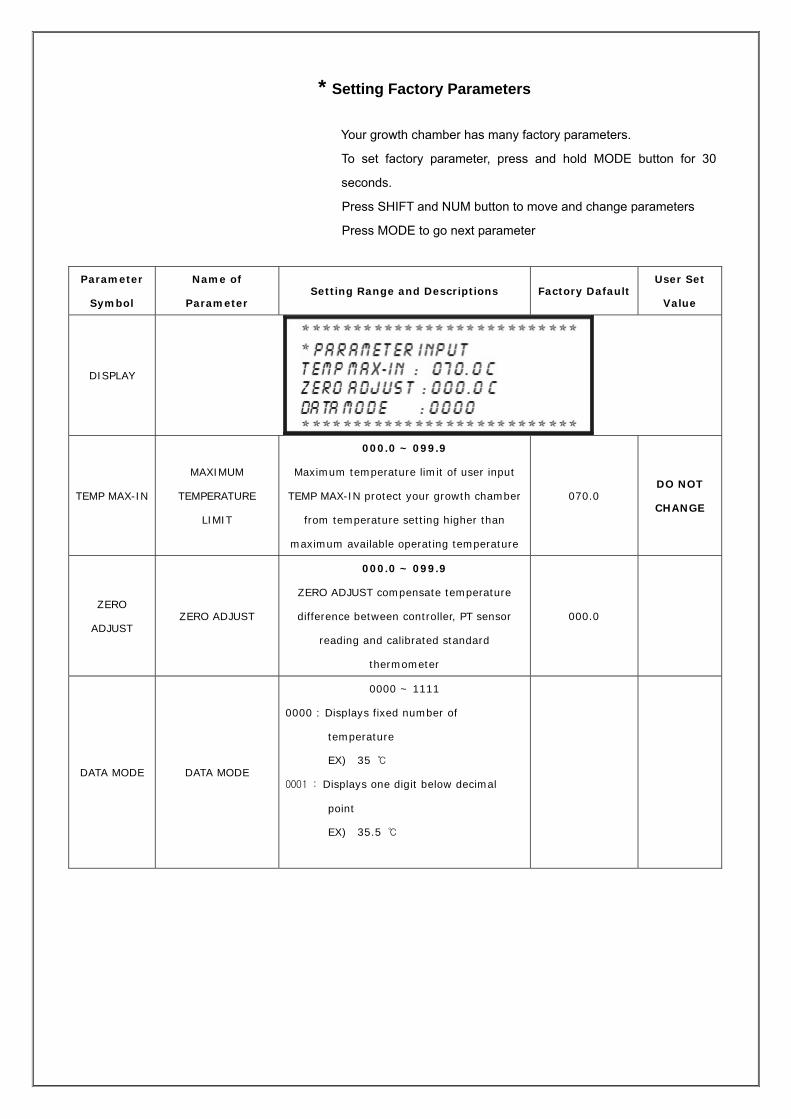
* Setting Factory Parameters
Your growth chamber has many factory parameters.
To set factory parameter, press and hold MODE button for 30
seconds.
Press SHIFT and NUM button to move and change parameters
Press MODE to go next parameter
Parameter
Symbol
Name of
Parameter Setting Range and Descriptions Factory Dafault
User Set
Value
DISPLAY
TEMP MAX-IN
MAXIMUM
TEMPERATURE
LIMIT
000.0 ~ 099.9
Maximum temperature limit of user input
TEMP MAX-IN protect your growth chamber
from temperature setting higher than
maximum available operating temperature
070.0 DO NOT
CHANGE
ZERO
ADJUST ZERO ADJUST
000.0 ~ 099.9
ZERO ADJUST compensate temperature
difference between controller, PT sensor
reading and calibrated standard
thermometer
000.0
DATA MODE DATA MODE
0000 ~ 1111
0000 : Displays fixed number of
temperature
EX) 35
0001 : Displays one digit below decimal
point
EX) 35.5

DISPLAY
HUMI MAX-IN
MAXIMUM
HUMIDITY
LIMIT
000.0 ~ 099.9
Maximum humidity reading where the
output signal from the sensor is 1V
DO NOT
CHANGE
ZERO
ADJUST ZERO ADJUST
000.0 ~ 099.9
ZERO ADJUST compensate humidity
difference between controller, humidity
sensor reading and calibrated standard
humidity sensor
000.0
DATA MODE DATA MODE
0000 ~ 1111
0000 : Displays fixed number of
humidity
EX) 80%
0001: Displays one digit below decimal
point
EX) 80.5 %
0000 : reserved
0010 : reserved
0000 : reserved
0100 : reserved
0000 : Use humidity control
1000 : Do not use humidity control
(Humidity value is not displaying on the
LCD display)

DISPLAY
CO2 MAX-IN MAXIMUM CO2
LIMIT
000.0 ~ 9999
Maximum CO2 reading where the output
signal from the sensor is 1V
DO NOT
CHANGE
ZERO
ADJUST ZERO ADJUST
000.0 ~ 9999
ZERO ADJUST compensate CO2 level
difference between controller, CO2 sensor
reading and calibrated standard CO2 sensor
0000
DATA MODE DATA MODE
0000 ~ 1111
0000 : Displays fixed number of CO2 Conc.
EX) 5 %
0001: Displays one digit below decimal
point
EX) 5.1 %
0000 : Displays CO2 level in %
0010 : Displays CO2 level in ppm
0000 : reserved
0100 : reserved
0000 : reserved
1000 : reserved

DISPLAY
LUX MAX-IN MAXIMUM LUX
LIMIT
000.0 ~ 9999
Maximum Illumination reading where the
output signal from the sensor is 1V
DO NOT
CHANGE
ZERO
ADJUST ZERO ADJUST
000.0 ~ 9999
ZERO ADJUST compensate illumination
intensity difference between controller,
sensor reading and calibrated standard
sensor
0000
DATA MODE DATA MODE
0000 ~ 1118
0000 : Number of lamps (do not use illumination)
0006 : Number of lamps (sex lamps installed)
0008 : Number of lamps (eight lamps installed)
0000 : reserved
0010 : reserved
0000 : reserved
0100 : reserved
0000 : Use illumination function
1000 : Do not use illumination function
(LUX value is not displaying on LCD
display)
0008 DO NOT
CHANGE

DISPLAY
TIMER START 000.0 ~ 99.9
Temperature where timer start count down
TIMER START
Absolute value (Current Temp. - Set Temp) > ACTP then timer starts
Temp Temp
Set temp - ACTP
set temp. set temp.
timer start timer end Time timer start timer end Time
Where ACTP = 0 Where ACTP > 0
DATA MODE DATA MODE
0000 ~ 1111
0000 : Program Memory Off
0001 : Program Memory On
Program and operating condition recovery
after power fail and restore
0000 : Time Scale in Minutes:Seconds (MM:SS)
0010 : Time Scale in Hour:Minutes (HH:MM)
0000 : reserved
0100 : reserved
0000 : reserved
1000 : reserved
0011
PASSWORD PASSWORD Password to protect unauthorized lock
control parameter change 0000

"A" : AC INLET
1 - 0 Volt 2 - 110 Volt 3 - 220 Volt
"B" : COOL RELAY (COOL ON – ON/STOP COOL OFF – OFF WHEN TIME END.)
1- NO RELAY 2- COMMON RELAY 3- NC RELAY
"C" : Water Supply Error Input ( REPLAY ON: ERROR, RELAY OFF: NORMAL)
"D" : Pt100 ohm Thermocouple Input
1: - (minus) 2: + (plus) 3: - (minus)
"E" : 0-1V Humidity Sensor Input
1: + (plus) 2: - (minus) 3: resrrved
"F" : 0-1V CO2 Sensor Input
1: + (plus) 2: - (minus)
"G" : 0-1V Lux Sensor Input
1: + (plus) 2: - (minus)
"H" : Triac Temperature Control Output
1- Triac gate
2- Triac MT2
"I" : Triac Humidity Control Output
1- Triac gate
2- Triac MT2
"J" : Triac CO2 Control Output
1- Triac gate
2- Triac MT2
"L8"-"L1" : 8 each of LAMP Triac ON/OFF Output Control
1- Triac gate
2- Triac MT2
(Remarks: On the LCD display,
where F:11111111 is
F : L8 L7 L6 L5 L4 L3 L2 L1

1.8. Warning
1. The main voltage must correspond to the voltage given on the name-
plate
2. Some parts of the growth chamber is extremely hot. Do not touch
any part of the growth chamber without personal safety device
during operation.
3. Place your growth chamber on the flat and level surface
4. Do not put volatile, flammable and explosive material in the
growth chamber.

1.9. Service Part List
Cabinet & Hardware Components Part# Part Material/Model Q’ty
GC-H007-1 Ceiling Glass Pair Glass 455x1355x5t 2 EA
GC-H007-2 Door Glass Glass 667x1502x5t 1 EA
GC-H008 Door Packing Silicone Foam Packing
Bumjin Type Packing 2 EA
GC-H010 Caster Poot master / 80 Kg 4 EA
GC-H011 Stop Bolt 27 x 100 mm EA
GC-H012 Door Handle D-9 Normal Handle 2 EA
GC-H013 Shelve Coated Shelve 5 EA
GC-H014 Shelve Support SUS 20 EA
GC-H015 Membrane Key Pad PVC 1 EA
GC-H016 Shock Absorber EA
Electric Components
Part# Part Model Specifications Q’ty
GC -E001 PID Controller BK4-PL Calibration Cert#:N/A 1 EA
GC -E003 PT-100 Sensor for PID Controller PT-100Ω Calibration Cert# : N/A 1 EA
GC-E004 Humidity Sensor tdk(R/T) 40~95RH, 4~20mA( 1~5v ) 250 ohm 1 EA
GC-E005 OPT Sensor (Hi-Temp.) Rainbow TS-120S AC250V 18A 1 EA
GC-E005-1 OPT Sensor (Low Temp.) PCC TS –20~40 10A 1 EA
GC -E006 Power S/W Series 82.X.X.8 16A 250 VAC 1 EA
GC-E007 Cool S/W Series 82.X.X.8 16A 250 VAC 1 EA
GC –E008 Circuit Breaker GRH-32 220/110V 1 EA
GC –E009 Heater for Heating 1.6KW 1 EA
GC-E009-1 Heater for Humidity 1.5KW EA
GC -E010 TRIAC TG25C60 100Ω 35A 8 EA
GC -E011 Fuse Holder HY-F15-1P AC 250V, 15A EA
GC -E012 Fuse 15A, 30mm 2 EA
GC -E013 Noise Filter WYF-S06A2 250 VAC, 6A
50/60Hz
1 EA
LGC-E014 Timer EH715 110/220V EA
GC -E015 Relay SLY-2S 250V 10A 2 EA
GC -E016 Relay Socket LR-LY2 250V 10A 2 EA
GC -E017 Power Relay DPR-302S 220V 7A 2 EA
GC -E018 Power Relay Socket DR-06 250V 10A EA
GC -E019 Packing Heater Silicon Heater 30W 1 SET
GC -E020 Heat Sink N027 70Χ80, 100Χ105 8 EA
GC -E021 Power Cord 250V 30A 1 EA
GC-E022 Terminal Strip SH-15A 25P25A, 4P30A, 3 EA

GC-E023 Solenoid Valve DS10 200A 200V 50/60Hz 1 EA
GC-E024 Fluorescent Lamp 40 Watt 22 EA
GC-E025 Metal Lamp MH250 EA
GC-E027 Fluorescent Lamp Ballast KSC810Z 230V60Hz 0.34A 42W 8 EA
GC-E028 Power Supply VSF15-24 50/60Hz 0.4A 264V EA
GC-E029 Fan NMB
STC
120Χ120 Χ40 220V 50/60Hz 4 EA
EA
Refrigeration Components
Part# Part Model Specifications Q’ty
GAB-R001 Compressor SC12G 1/3HP 220~240V 50/60Hz
Danfuss
2 EA
GAB-R002 Air Cooled
Condenser
CCI-04 0.4 Kw
Surface Area : 2.9 m2
Capacity : 525 kCal/hr
Fitting : INPUT 3/8” OUTPUT 3/8”
2 EA
GAB-R003 Evaporator 580x110x160 mm 2 EA
GAB-R004 Condenser Fan FS-20 225φ 2 EA
GAB-R005 Condenser Motor IS-4415YSA AC220V 50/60Hz 9W 4P 2 EA
GAB-R006 Condenser YP04P 1072 40 uF –0/20% (65C) 330V 50/60Hz 2 EA
GAB-R007 Compressor Relay MSRL 59D98
M107
2 EA
GAB-R008 Compressor OPT T150 T0517/55
GAB-R009 Dryer Filter ADK-032 2 EA
GAB-R010 Anti Vibration Rubber
Support
Φ30 x 22x 4 ea 2 SET
GAB-R011 Capillary Copper Wire Dia. 2.2φ x 1500mm 1 SET
GAB-R012 Refrigerant R-134A
GAB-R013 Solenoid Valve Y-267 220V 1 EA


