12
TW-7700 Operating Manual FISHER RESEARCH LABORATORY Digital Line Tracer
Q U A L I T YFisher detectors are renowned for their quality.
Each detector is hand crafted in the USA with pride
P E R F O R M A N C EThe worldwide underground utility industry relys on Fisher.
Our instruments are durable, dependable, and locate deeper.
R E P U T A T I O NFisher produced the first patented metal detector in 1931. For over 70 years, the Fisher logo has been a mark of excellence.
2 - YEAR LIMITED WARRANTYFisher believes in the products we produce and backs this belief
with a 2 year limited warranty.
Proof of purchase is required to make a claim under this warranty.
NOTE TO CUSTOMERS OUTSIDE THE U.S.A.This warranty may vary in other countries, check with your
distributor for details.Factory warranty follows the channel of distribution.
Warranty does not cover shipping costs.
S E R V I C EFisher is committed to providing you, our valued customer, with
superior service. Each and every instrument is rigidly tested and carefully inspected during assembly and before shipment.
Should you have any questions or problems, contact:
FISHER RESEARCH LABORATORY1465-H Henry Brennan, El Paso, Texas 79936
Tel 915.225.0333 Fax 915.225.0336www.fisherlab.com email:[email protected]
TW-7700
Operating ManualF I S H E R R E S E A R C H L A B O R A T O R Y
Digital Line Tracer
According to FCC part 15.21 Changes or Modifications made to this device not expressly approved by the party responsible for compliance could void
the users authority to operate this equipment.
FRL 8708002000 06-09-10

Description .............................................................................. pg. 3Transmitter ............................................................................ pg. 4Receiver ................................................................................... pg. 6Accessories .............................................................................. pg. 8Operating Instructions ........................................................ pg. 9Depth Accuracy ...................................................................... pg. 10Specifications ......................................................................... pg. 11
CONTENTS SPECIFICATIONSSubject to improvement or modification without notice.
TRANSMITTER
RECEIVERDepth Accuracy ........................+1 inch per foot in nominal conditionsReadout Units .......................... Inches or cm (factory preset)Left/Right Guidance .................Audio: continuous tone=Left, pulsed tone=Right. VCO (varying pitch) output for easy over ............................................ target location. Visual: Left/Right/ ............................................Over Target messagesSignal Strength ........................Digital Numeric Readout (0-99%) & Bar GraphSensitivity Adjust .....................AutomaticLCD Backlight .......................... IncludedBattery Test ..............................Automatic Low Battery alert Push button readoutBattery Type .............................Six “C” cellsBattery Life ..............................80 HoursWeight .......................................5.4 lbs.Operating Temp ....................... -4 0 to +1400F (-200 to +600C)
Fisher Research Laboratory does not warrant suitability to specific use. Fisher Research Laboratory shall in no event be liable for any direct, incidental, conse-quential or indirect damages.
Output Frequency ....................82.175 kHzOutput Power (nominal) ..........Normal Setting = 0.25 watt High Setting = 1.0 wattConductive Tracing ..................2 to 3,000 ohms normal power-6dBMagnetic Strength ...................2 to 8,000 ohms high power-6dBInductive Tracing .....................15 Vm2, normal powerMagnetic Strength ...................25 Vm2, high powerBattery Type .............................Four D-cell batteries (included)Battery Life ..............................160 hours in normal power modeWeight, with batteries ..............3.73 lbs
11
DESCRIPTION
1
3
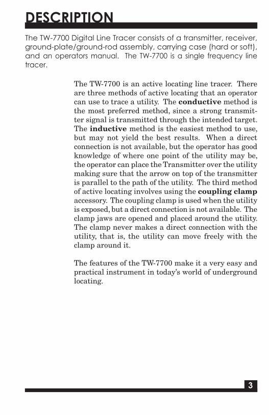
The TW-7700 Digital Line Tracer consists of a transmitter, receiver, ground-plate/ground-rod assembly, carrying case (hard or soft), and an operators manual. The TW-7700 is a single frequency line tracer.
The TW-7700 is an active locating line tracer. There are three methods of active locating that an operator can use to trace a utility. The conductive method is the most preferred method, since a strong transmit-ter signal is transmitted through the intended target. The inductive method is the easiest method to use, but may not yield the best results. When a direct connection is not available, but the operator has good knowledge of where one point of the utility may be, the operator can place the Transmitter over the utility making sure that the arrow on top of the transmitter is parallel to the path of the utility. The third method of active locating involves using the coupling clamp accessory. The coupling clamp is used when the utility is exposed, but a direct connection is not available. The clamp jaws are opened and placed around the utility. The clamp never makes a direct connection with the utility, that is, the utility can move freely with the clamp around it.
The features of the TW-7700 make it a very easy and practical instrument in today’s world of underground locating.
10
DEPTH ACCURACY
Depth measurement is a feature of the TW-7700. Accuracy is defined on an ideal target, that is, one that is continuous, a good conductor, and not surrounding by other utilities. There are factors that can cause the operator to question the accu-racy of the utility being traced.
Inductive Transmitter SetupInductively, only a small portion of the signal attaches it-self to the utility. With a weakened signal, trace should be accurate, but depth may not. The conductive method will yield better results.Low Receiver Signal StrengthWhen the signal strength falls below 20 – 25%, depth read-out may not be accurate. It would be beneficial to move the transmitter to a closer point of contact.Nearby UtilitiesClose, nearby utilities may have some influence on the accuracy of the Depth readout. This is more prone to hap-pen in the higher frequencies where signals can jump to nearby utilities. Switching to a lower frequency can give better results.MoistureGround that is too dry or overly saturated may skew the depth readout.“T’s”, elbows, or splits in the utility can distort the transmitted signal in that general area.
WARNING: Do not connect output leads to a live (energized) utility. Please prevent shock hazard and equipment damage.

94
TW-7700 TRANSMITTER
Transmitter
The TW-7700 Transmitter.
The Transmitter has two controls: On/Off & Power/Mode.The Power/Mode Button has a dual function1. When transmitter is powered on, Power/Mode switches
between normal (1/4 watt) and high (1.0 watt) output.2. When transmitter is powered off, press-and-hold Power/Mode to program the Auto Power-Down feature.
With the Auto Power-Down feature activated, the Transmitter will automatically turn off 30 minutes after the last key-pad press by the user.
This is a battery-saving feature.
With the unit powered off (and Power/Mode depressed), successive presses of On/Off will show a flashing battery indictor, followed by a blank screen or the illuminated battery indicator.
• An illuminated Battery Indicator means that Auto Power-Down is activated
• A blank screen means that Auto Power-Down is deactivated.
Set-up Transmitter either Inductively or ConductivelyInductiveBe aware of air coupling, the transmitted signal travelling to the Receiver via the air, not the utility. Conductive Connect the ground plate/ground rod assembly to the trans-mitter. Connect the red lead to the non-energized utility. Connect the black lead to the ground plate/ground rod. Place the plate/rod at a 90 degree angle in reference to the utility. Be sure not to place the wires over any other utility. After transmitter set-up, move away from the point of con-nection (or Induction) about 25 feet (8 meters). Sweep a circle around the point of connection. Initially, disregard the LEFT/RIGHT indicator and rely on the signal strength read-out. Make note of the high readings. These are areas that need to be traced/examined in more detail.TracingAfter locating the point(s) where the signal strength was the highest, return to that/those points and start tracing your util-ity. This is where the LEFT/RIGHT indicator is very helpful. Swing the receiver from left to right and listen for the change of tone. When the target is to the RIGHT of the receiver, the tone is pulsed tone. As the receiver gets closer to the target, the pitch gets higher. When the target is to the LEFT of the receiver, the tone is a continuous tone. As the receiver gets close to the target, the pitch also becomes higher. When the receiver is over the target, OVER TARGET is displayed on the display screen, and the tone is at its highest peak sound.Depth MeasuringWhen an OVER TARGET response is displayed, position the blade of the receiver directly over the utility and place the tip on the ground. Hold the receiver steady, press and hold the DEPTH pad. Depth will be measured to the center of the utility.
INITIAL SCAN
OPERATING INSTRUCTIONSThe following instructions are designed for a safe and effective method of line tracing and utility avoidance. Some of the steps may not be applicable in all situations. The underlying guide-line is that operator safety must be maintained at all times. Use of safety equipment, extra personnel, and up to date as-built plans should be considered when necessary.

58
ACCESSORIES
The coupling clamp is useful when the utility is exposed, and a direct connection is not possible. It is plugged into the same plug-in socket as the ground-plate/ground-rod assembly. The coupling clamp only operates at the 82 kHz frequency. The coupling clamp will fit around utilities that are 3-¼ inches in diameter or smaller. The length of the cable is approximately 10 feet.
Coupling Clamp
Fisher Research Laboratory has a variety of headsets avail-able. •Ultra-quiet deluxe Fisher Phones. High quality sound while reducing the outside noise.•Standard Stereo Headphones•Single Earpiece Headset. Enables the operator to effec-tively listen to the TW-7700 and remain aware of noise in close proximity.
Headsets
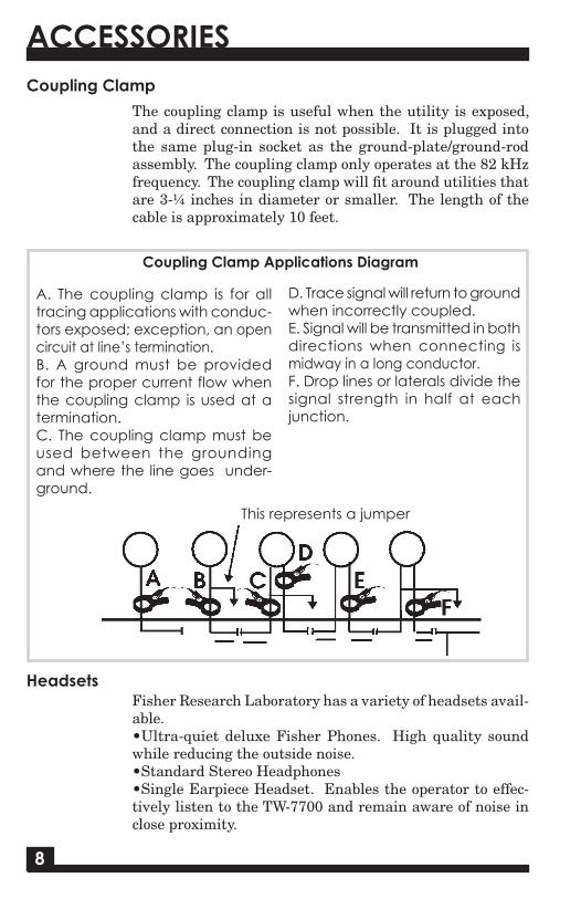
This represents a jumper
Coupling Clamp Applications Diagram
A. The coupling clamp is for all tracing applications with conduc-tors exposed; exception, an open circuit at line’s termination.B. A ground must be provided for the proper current flow when the coupling clamp is used at a termination.C. The coupling clamp must be used between the grounding and where the line goes under-ground.
D. Trace signal will return to ground when incorrectly coupled.E. Signal will be transmitted in both directions when connecting is midway in a long conductor.F. Drop lines or laterals divide the signal strength in half at each junction.
TW-7700 TRANSMITTER
WARNING: Do not handle output leads unless power is off.ELECTRIC SHOCK HAZARD: Servicing to be performed by qualified personnel only.
After you release Power/Mode, the transmitter power will turn on.
Accessory Output1. Flip up the black protective cover to expose the
Accessory Output.2. Plug in the Cable Jack for conductive tracing.
When the conductive tracing cable is connected, Signal Current will be displayed. The Signal Current Bar Graph shows the quality of the connection.
Automatic Load Impedance Matching adjusts output to provide full rated power over a wide range of loads (e.g. utility types and conditions). It is tolerant of both dry (high resistance) and shunted (low resistance) ground connections.
The Transmitter has a built-in antenna for inductive locating.When the Cable Jack is not connected, the inductive antenna automatically engages and begins transmitting. When locating inductively, the Signal Current Bar Graph will not be displayed, as there is no conductive trace load to be measured.

76
TW-7700 RECEIVER
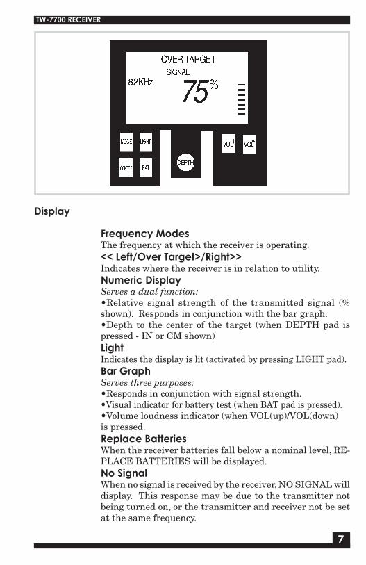
Frequency ModesThe frequency at which the receiver is operating.<< Left/Over Target>/Right>>Indicates where the receiver is in relation to utility.Numeric DisplayServes a dual function:•Relative signal strength of the transmitted signal (% shown). Responds in conjunction with the bar graph. •Depth to the center of the target (when DEPTH pad is pressed - IN or CM shown) Light Indicates the display is lit (activated by pressing LIGHT pad).Bar Graph Serves three purposes:•Responds in conjunction with signal strength.•Visual indicator for battery test (when BAT pad is pressed).•Volume loudness indicator (when VOL(up)/VOL(down) is pressed.Replace BatteriesWhen the receiver batteries fall below a nominal level, RE-PLACE BATTERIES will be displayed.No SignalWhen no signal is received by the receiver, NO SIGNAL will display. This response may be due to the transmitter not being turned on, or the transmitter and receiver not be set at the same frequency.
Display
Receiver
ModeThis button does not have a function on the TW-7700. (It allows users of the TW-8800 Multi-Frequency Line Tracer to change frequencies.)Power On/OffTurns the receiver on or off. Light Lights up the display for usage in dark areas. When the display is backlit, LIGHT is shown on the bottom left hand side of the display screen.BatPress and hold this pad to check the battery level of the re-ceiver. A bar graph on the right side of the display will give status of the batteries. When the graph shows 1 bar, it is time to replace the batteries. Additionally, as the operator uses the Receiver, if the batteries get low, REPLACE BATTERIES will appear in the lower area of the Display screen.Vol(up)/Vol(down)Increases or decreases the volume of the speaker.Depth After determining the centerline of the utility, set the blade of the receiver on the ground, press and hold this pad to get the depth to the center of the target.
TW-7700 RECEIVER
Controls
The TW-7700 Receiver.
76
TW-7700 RECEIVER
Frequency ModesThe frequency at which the receiver is operating.<< Left/Over Target>/Right>>Indicates where the receiver is in relation to utility.Numeric DisplayServes a dual function:•Relative signal strength of the transmitted signal (% shown). Responds in conjunction with the bar graph. •Depth to the center of the target (when DEPTH pad is pressed - IN or CM shown) Light Indicates the display is lit (activated by pressing LIGHT pad).Bar Graph Serves three purposes:•Responds in conjunction with signal strength.•Visual indicator for battery test (when BAT pad is pressed).•Volume loudness indicator (when VOL(up)/VOL(down) is pressed.Replace BatteriesWhen the receiver batteries fall below a nominal level, RE-PLACE BATTERIES will be displayed.No SignalWhen no signal is received by the receiver, NO SIGNAL will display. This response may be due to the transmitter not being turned on, or the transmitter and receiver not be set at the same frequency.
Display
Receiver
ModeThis button does not have a function on the TW-7700. (It allows users of the TW-8800 Multi-Frequency Line Tracer to change frequencies.)Power On/OffTurns the receiver on or off. Light Lights up the display for usage in dark areas. When the display is backlit, LIGHT is shown on the bottom left hand side of the display screen.BatPress and hold this pad to check the battery level of the re-ceiver. A bar graph on the right side of the display will give status of the batteries. When the graph shows 1 bar, it is time to replace the batteries. Additionally, as the operator uses the Receiver, if the batteries get low, REPLACE BATTERIES will appear in the lower area of the Display screen.Vol(up)/Vol(down)Increases or decreases the volume of the speaker.Depth After determining the centerline of the utility, set the blade of the receiver on the ground, press and hold this pad to get the depth to the center of the target.
TW-7700 RECEIVER
Controls
The TW-7700 Receiver.
58
ACCESSORIES
The coupling clamp is useful when the utility is exposed, and a direct connection is not possible. It is plugged into the same plug-in socket as the ground-plate/ground-rod assembly. The coupling clamp only operates at the 82 kHz frequency. The coupling clamp will fit around utilities that are 3-¼ inches in diameter or smaller. The length of the cable is approximately 10 feet.
Coupling Clamp
Fisher Research Laboratory has a variety of headsets avail-able. •Ultra-quiet deluxe Fisher Phones. High quality sound while reducing the outside noise.•Standard Stereo Headphones•Single Earpiece Headset. Enables the operator to effec-tively listen to the TW-7700 and remain aware of noise in close proximity.
Headsets
This represents a jumper
Coupling Clamp Applications Diagram
A. The coupling clamp is for all tracing applications with conduc-tors exposed; exception, an open circuit at line’s termination.B. A ground must be provided for the proper current flow when the coupling clamp is used at a termination.C. The coupling clamp must be used between the grounding and where the line goes under-ground.
D. Trace signal will return to ground when incorrectly coupled.E. Signal will be transmitted in both directions when connecting is midway in a long conductor.F. Drop lines or laterals divide the signal strength in half at each junction.
TW-7700 TRANSMITTER
WARNING: Do not handle output leads unless power is off.ELECTRIC SHOCK HAZARD: Servicing to be performed by qualified personnel only.
After you release Power/Mode, the transmitter power will turn on.
Accessory Output1. Flip up the black protective cover to expose the
Accessory Output.2. Plug in the Cable Jack for conductive tracing.
When the conductive tracing cable is connected, Signal Current will be displayed. The Signal Current Bar Graph shows the quality of the connection.
Automatic Load Impedance Matching adjusts output to provide full rated power over a wide range of loads (e.g. utility types and conditions). It is tolerant of both dry (high resistance) and shunted (low resistance) ground connections.
The Transmitter has a built-in antenna for inductive locating.When the Cable Jack is not connected, the inductive antenna automatically engages and begins transmitting. When locating inductively, the Signal Current Bar Graph will not be displayed, as there is no conductive trace load to be measured.
94
TW-7700 TRANSMITTER
Transmitter
The TW-7700 Transmitter.
The Transmitter has two controls: On/Off & Power/Mode.The Power/Mode Button has a dual function1. When transmitter is powered on, Power/Mode switches
between normal (1/4 watt) and high (1.0 watt) output.2. When transmitter is powered off, press-and-hold Power/Mode to program the Auto Power-Down feature.
With the Auto Power-Down feature activated, the Transmitter will automatically turn off 30 minutes after the last key-pad press by the user.
This is a battery-saving feature.
With the unit powered off (and Power/Mode depressed), successive presses of On/Off will show a flashing battery indictor, followed by a blank screen or the illuminated battery indicator.
• An illuminated Battery Indicator means that Auto Power-Down is activated
• A blank screen means that Auto Power-Down is deactivated.
Set-up Transmitter either Inductively or ConductivelyInductiveBe aware of air coupling, the transmitted signal travelling to the Receiver via the air, not the utility. Conductive Connect the ground plate/ground rod assembly to the trans-mitter. Connect the red lead to the non-energized utility. Connect the black lead to the ground plate/ground rod. Place the plate/rod at a 90 degree angle in reference to the utility. Be sure not to place the wires over any other utility. After transmitter set-up, move away from the point of con-nection (or Induction) about 25 feet (8 meters). Sweep a circle around the point of connection. Initially, disregard the LEFT/RIGHT indicator and rely on the signal strength read-out. Make note of the high readings. These are areas that need to be traced/examined in more detail.TracingAfter locating the point(s) where the signal strength was the highest, return to that/those points and start tracing your util-ity. This is where the LEFT/RIGHT indicator is very helpful. Swing the receiver from left to right and listen for the change of tone. When the target is to the RIGHT of the receiver, the tone is pulsed tone. As the receiver gets closer to the target, the pitch gets higher. When the target is to the LEFT of the receiver, the tone is a continuous tone. As the receiver gets close to the target, the pitch also becomes higher. When the receiver is over the target, OVER TARGET is displayed on the display screen, and the tone is at its highest peak sound.Depth MeasuringWhen an OVER TARGET response is displayed, position the blade of the receiver directly over the utility and place the tip on the ground. Hold the receiver steady, press and hold the DEPTH pad. Depth will be measured to the center of the utility.
INITIAL SCAN
OPERATING INSTRUCTIONSThe following instructions are designed for a safe and effective method of line tracing and utility avoidance. Some of the steps may not be applicable in all situations. The underlying guide-line is that operator safety must be maintained at all times. Use of safety equipment, extra personnel, and up to date as-built plans should be considered when necessary.

DESCRIPTION
1
3
The TW-7700 Digital Line Tracer consists of a transmitter, receiver, ground-plate/ground-rod assembly, carrying case (hard or soft), and an operators manual. The TW-7700 is a single frequency line tracer.
The TW-7700 is an active locating line tracer. There are three methods of active locating that an operator can use to trace a utility. The conductive method is the most preferred method, since a strong transmit-ter signal is transmitted through the intended target. The inductive method is the easiest method to use, but may not yield the best results. When a direct connection is not available, but the operator has good knowledge of where one point of the utility may be, the operator can place the Transmitter over the utility making sure that the arrow on top of the transmitter is parallel to the path of the utility. The third method of active locating involves using the coupling clamp accessory. The coupling clamp is used when the utility is exposed, but a direct connection is not available. The clamp jaws are opened and placed around the utility. The clamp never makes a direct connection with the utility, that is, the utility can move freely with the clamp around it.
The features of the TW-7700 make it a very easy and practical instrument in today’s world of underground locating.
10
DEPTH ACCURACY
Depth measurement is a feature of the TW-7700. Accuracy is defined on an ideal target, that is, one that is continuous, a good conductor, and not surrounding by other utilities. There are factors that can cause the operator to question the accu-racy of the utility being traced.
Inductive Transmitter SetupInductively, only a small portion of the signal attaches it-self to the utility. With a weakened signal, trace should be accurate, but depth may not. The conductive method will yield better results.Low Receiver Signal StrengthWhen the signal strength falls below 20 – 25%, depth read-out may not be accurate. It would be beneficial to move the transmitter to a closer point of contact.Nearby UtilitiesClose, nearby utilities may have some influence on the accuracy of the Depth readout. This is more prone to hap-pen in the higher frequencies where signals can jump to nearby utilities. Switching to a lower frequency can give better results.MoistureGround that is too dry or overly saturated may skew the depth readout.“T’s”, elbows, or splits in the utility can distort the transmitted signal in that general area.
WARNING: Do not connect output leads to a live (energized) utility. Please prevent shock hazard and equipment damage.

Description .............................................................................. pg. 3Transmitter ............................................................................ pg. 4Receiver ................................................................................... pg. 6Accessories .............................................................................. pg. 8Operating Instructions ........................................................ pg. 9Depth Accuracy ...................................................................... pg. 10Specifications ......................................................................... pg. 11
CONTENTS SPECIFICATIONSSubject to improvement or modification without notice.
TRANSMITTER
RECEIVERDepth Accuracy ........................+1 inch per foot in nominal conditionsReadout Units .......................... Inches or cm (factory preset)Left/Right Guidance .................Audio: continuous tone=Left, pulsed tone=Right. VCO (varying pitch) output for easy over ............................................ target location. Visual: Left/Right/ ............................................Over Target messagesSignal Strength ........................Digital Numeric Readout (0-99%) & Bar GraphSensitivity Adjust .....................AutomaticLCD Backlight .......................... IncludedBattery Test ..............................Automatic Low Battery alert Push button readoutBattery Type .............................Six “C” cellsBattery Life ..............................80 HoursWeight .......................................5.4 lbs.Operating Temp ....................... -4 0 to +1400F (-200 to +600C)
Fisher Research Laboratory does not warrant suitability to specific use. Fisher Research Laboratory shall in no event be liable for any direct, incidental, conse-quential or indirect damages.
Output Frequency ....................82.175 kHzOutput Power (nominal) ..........Normal Setting = 0.25 watt High Setting = 1.0 wattConductive Tracing ..................2 to 3,000 ohms normal power-6dBMagnetic Strength ...................2 to 8,000 ohms high power-6dBInductive Tracing .....................15 Vm2, normal powerMagnetic Strength ...................25 Vm2, high powerBattery Type .............................Four D-cell batteries (included)Battery Life ..............................160 hours in normal power modeWeight, with batteries ..............3.73 lbs
11

Q U A L I T YFisher detectors are renowned for their quality.
Each detector is hand crafted in the USA with pride
P E R F O R M A N C EThe worldwide underground utility industry relys on Fisher.
Our instruments are durable, dependable, and locate deeper.
R E P U T A T I O NFisher produced the first patented metal detector in 1931. For over 70 years, the Fisher logo has been a mark of excellence.
2 - YEAR LIMITED WARRANTYFisher believes in the products we produce and backs this belief
with a 2 year limited warranty.
Proof of purchase is required to make a claim under this warranty.
NOTE TO CUSTOMERS OUTSIDE THE U.S.A.This warranty may vary in other countries, check with your
distributor for details.Factory warranty follows the channel of distribution.
Warranty does not cover shipping costs.
S E R V I C EFisher is committed to providing you, our valued customer, with
superior service. Each and every instrument is rigidly tested and carefully inspected during assembly and before shipment.
Should you have any questions or problems, contact:
FISHER RESEARCH LABORATORY1465-H Henry Brennan, El Paso, Texas 79936
Tel 915.225.0333 Fax 915.225.0336www.fisherlab.com email:[email protected]
TW-7700
Operating ManualF I S H E R R E S E A R C H L A B O R A T O R Y
Digital Line Tracer
According to FCC part 15.21 Changes or Modifications made to this device not expressly approved by the party responsible for compliance could void
the users authority to operate this equipment.
FRL 8708002000 06-09-10


