36
941211-000 -D1 OPERATING MANUAL SESAM 800 L15, M6, S6, S3, K3, RXD, RX, RX DIN
941211-000 -D1
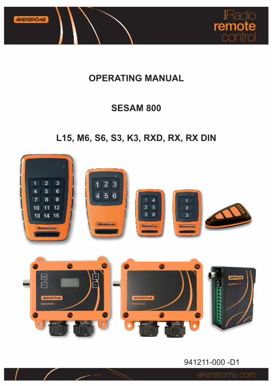
OPERATING MANUAL
SESAM 800
L15, M6, S6, S3, K3, RXD, RX, RX DIN

2 (36)
Sesam 800 Operating Manual Document-ID: 941211-000Version: D1 Author: SH
Table of Contents1 Introduction _________________________________________ 4
2 Scope _____________________________________________ 4
3 TechnicalSpecifications _______________________________ 5
4 Description of the System _____________________________ 74.1 Receivers ________________________________________________74.2 Transmitters ______________________________________________8
5 Description of the Receivers ___________________________ 9
6 Installation of the Receiver ____________________________ 126.1 Placement of the Receiver __________________________________126.2 Antenna Placement ________________________________________136.3 Connections on the Receiver (All Models) ______________________13
7 Indicators On the Receivers ___________________________ 147.1 Sesam 800 RX ___________________________________________147.2 Sesam 800 RXD Model _____________________________________157.3 Sesam 800 RX DIN ________________________________________15
8 ConfigurationOftheReceiver _________________________ 168.1 Sesam 800 RX Model ______________________________________168.1.1 BasicConfiguration ______________________________________________ 16
8.1.2 AdvancedConfiguration ___________________________________________ 17
8.1.3 ErasingAllTransmittersintheReceiver _______________________________ 17
8.2 Sesam 800 RXD Model _____________________________________188.2.1 BasicConfiguration ______________________________________________ 18
8.2.2 AdvancedConfiguration ___________________________________________ 18
8.2.3 ErasingTransmittersintheReceiverSESAM800RXD __________________ 20
8.2.4 Re-configuringaTransmitterintheReceiver __________________________ 20
8.2.5 PIN Lock in the Receiver __________________________________________ 21
3 (36)
Sesam 800 Operating Manual Document-ID: 941211-000Version: D1 Author: SH
8.3 Sesam 800 RX DIN _______________________________________238.3.1 BasicConfiguration ______________________________________________ 23
8.3.2 AdvancedConfiguration ___________________________________________ 23
8.3.3 ErasingAllTransmittersintheReceiverSESAM800RXDIN ______________ 24
8.4 HighSecurityTransmissionModeforRXandRXD _______________258.5 MemoryCard(OnlyRXD) ___________________________________268.5.1 CopyingInformationfromaMemoryCardtoaNewReceiver ______________ 26
8.5.2 CopyingInformationfromaReceivertoaMemoryCard __________________ 27
9 Description of the Transmitters ________________________ 289.1 Indicators on the Transmitter _________________________________28
10 ReplacingBatteriesintheTransmitters _________________ 3010.1 ReplacingBatteriesinSesamK3 _____________________________3010.2 ReplacingBatteriesintheSesam800S3&S6 __________________3110.3 ReplacingBatteriesinSesam800M6 _________________________3210.4 ReplacingBatteriesintheSesam800L15 ______________________33
11 Error Codes ________________________________________ 3411.1 Error Codes, Sesam 800 RXD _______________________________3411.2 Error Codes, Sesam 800 RX and RX DIN ______________________34
12 Receiver Drill Measure for RX and RXD _________________ 3512.1 MeasureforRXDIN _______________________________________35
Introduction 4 (36)
Sesam 800 Operating Manual Document-ID: 941211-000Version: D1 Author: SH
1 IntroductionThis manual only covers the installation of the Sesam radio remote door opening system. The Sesam System is not a complete door opening system: it provides only the set of outputs that are driven according to the actions performed by the operator of the transmitter. The way the set of outputs is used for controlling the doors depends on the specific installation and is outside the scope of the Sesam.
The complete remote control system, where the controlled object is one part, has to be tested and approved according to the standards/norms that are ap-plicable and specific to the controlled object. This is not the responsibility of Åkerströms Björbo.
2 ScopeThe following guide must be used when installing Åkerströms Sesam door opening system to ensure secure, safe operation. The installation must be car-ried out by a certified electrician.
Technical Specifications 5 (36)
Sesam 800 Operating Manual Document-ID: 941211-000Version: D1 Author: SH
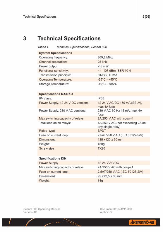
3 TechnicalSpecificationsTabell 1. TechnicalSpecifications,Sesam800
SystemSpecificationsOperating frequency: 869,8 MHz Channel separation: 25 kHzPower output: < 5 mWFunctional sensitivity: <= -107 dBm BER 10-4Transmission principle: GMSK, TDMAOperating Temperature: -25°C - +55°CStorage Temperature: -40°C - +85°C
SpecificationsRX/RXDIP- class: IP65Power Supply, 12-24 V DC versions: 12-24 V AC/DC 150 mA (SELV),
max 4A fusePower Supply, 230 V AC versions: 230 V AC 50 Hz 15 mA, max 4A
fuseMax switching capacity of relays: 2A/250 V AC with cosφ=1Total load on all relays: 4A/250 V AC (not exceeding 2A on
any single relay)Relay- type SPDTFuse on current loop: 2,5AT/250 V AC (IEC 60127-2/V)Dimensions: 135 x120 x 50 mmWeight: 450gScrew size TX20
SpecificationsDINPower Supply 12-24 V AC/DCMax switching capacity of relays: 2A/250 V AC with cosφ=1Fuse on current loop: 2,5AT/250 V AC (IEC 60127-2/V)Dimensions: 92 x72,5 x 30 mmWeight: 84g

Technical Specifications 6 (36)
Sesam 800 Operating Manual Document-ID: 941211-000Version: D1 Author: SH
SpecificationsK3IP- class: IP65Dimensions: 67x44x13 mmWeight: 30gBattery type: 2* CR 2025 Lithium cellsScrew Size PH00
SpecificationsS3IP- class: IP67Dimensions: 75 x 46 x 22 mmWeight: 80gBattery type: 2*AAA/LR03 AlkalineScrew Size PH00
SpecificationsS6IP- class: IP67Dimensions: 75 x 46 x 22 mmWeight: 80gBattery type: 2*AAA/LR03 AlkalineScrew Size PH00
SpecificationsM6IP- class: IP67Dimensions: 100 x 60 x 25 mmWeight: 130gBattery type: 2*AA/LR06 AlkalineScrew Size PH2
SpecificationsL15IP- class: IP67Dimensions: 120x75x30Weight: 200gBattery type: 2*AA/LR06 AlkalineScrew Size PH2There is also a L99 with a display. For information see the Installation Manual SESAM L99, 800RX and 800RXD

Description of the System 7 (36)
Sesam 800 Operating Manual Document-ID: 941211-000Version: D1 Author: SH
4 Description of the System
4.1 ReceiversThis document covers three receiver models. RX, RXD and RX DIN. RX and RXD can be ordered as 230 V AC or 12-24 V AC/DC. RX DIN only as 12-24 V AC/DC.
Sesam 800 RX:
• 3 Single Pole Double Throw relays.
• Memory capacity: up to 100 transmitters.
Sesam 800 RXD:
• 3 Single Pole Double Throw relays.
• Integrated display and configuration buttons.
• Memory capacity: up to 500 transmitters.
• The receiver can be equipped with an detachable memory card containing a backup of all configuration parameters.
Sesam 800 RX DIN:
• 3 Single Pole Double Throw relays.
• Memory capacity: up to 100 transmitters.
• Designed for DIN rail
Description of the System 8 (36)
Sesam 800 Operating Manual Document-ID: 941211-000Version: D1 Author: SH
4.2 TransmittersThis document covers five transmitter models:
Keyring K3:
• Miniature 3 button transmitter.
• Suitable for controlling 3 non-response time critical func tions.
Small S3:
• Small size 3 button transmitter.
• Suitable for controlling 3 func tions.
Small S6:
• Small size 6 button transmitter.
• Suitable for controlling 6 func tions.
Medium M6:
• Medium size 6 button transmitter.
• Suitable for controlling 6 functions and/or where a larger transmitter is preferred, for example industrial applications.
Large L15:
• Large 15 button transmitter.
• Suitable for controlling up to 15 functions, for example industrial applica-tions.

Description of the Receivers 9 (36)
Sesam 800 Operating Manual Document-ID: 941211-000Version: D1 Author: SH
5 Description of the Receivers
1 2 3 4 5 6 7 8 9
R1 R2 R3
4
567
12
3
89
14
10 11 12 13
Figure1.Sesam 800 RX 230 V AC model indicators, connections andjumper. 1.LED1Relay1status 2.LED2Relay2status 3.LED3Relay3status 4.LED4Power 5.LED5Squelch 6.LED6Status 7. LED 7 Learn 8.Powerconnection230VAC 9.JumperJ1HighSecurity TransmissionModesetting 10.Learn/Erasebutton 11.Connectiontorelay1 12.Connectiontorelay2 13.Connectiontorelay3 14. Antenna connector
1 2 3 4 5 6 7 8 9
R1 R2 R3
4
567
12
3
89
14
10 11 12 13
Figure2.Sesam 800 RX 12-24 V DC model indicators, connections and jumper. 1.LED1Relay1status 2.LED2Relay2status 3.LED3Relay3status 4.LED4Power 5.LED5Squelch 6.LED6Status 7. LED 7 Learn 8.Powerconnection12-24VAC/DC 9.JumperJ1HighSecurity TransmissionModesetting 10.Learn/Erasebutton 11.Connectiontorelay1 12.Connectiontorelay2 13.Connectiontorelay3 14. Antenna connector

Description of the Receivers 10 (36)
Sesam 800 Operating Manual Document-ID: 941211-000Version: D1 Author: SH
1 2 3 4
5
Figure3. Sesam 800 RXD 12-24 V DC/AC model connections 1.Powerconnection 2.Connectiontorelay1 3.Connectiontorelay2 4.Connectiontorelay3 5. Antenna connector
1 2 3 4
5
Figure4. Sesam 800 RXD 230 V AC model connections 1.Powerconnection, 2.Connectiontorelay1 3.Connectiontorelay2 4.Connectiontorelay3 5. Antenna connector

Description of the Receivers 11 (36)
Sesam 800 Operating Manual Document-ID: 941211-000Version: D1 Author: SH
1 2
34
5
Figure5. Sesam800RXDmodeldisplayandbuttons 1.Learn/Erasebutton 2.Enterbutton 3.Memorypositionupbutton 4.Memorypositiondownbutton 5.Display
Figure6. Sesam 800 RX DIN model connectionsandbuttons 1.Learn/Erasebutton 2.Powerconnection, 3.Connectiontorelay1 4.Connectiontorelay2 5.Connectiontorelay3 6.LED5Squelch LED6Status LED 7 Learn

Installation of the Receiver 12 (36)
Sesam 800 Operating Manual Document-ID: 941211-000Version: D1 Author: SH
6 Installation of the ReceiverThe permanent installation of the receiver must include fuses that protect the equipment and wiring from over current and short-circuit. In detail the power supply of the receiver and all relay contacts must be fused.
All fuses are used as disconnecting devices. The fuses shall be easily accessible, must submit a contact gap of at least 3.0 mm and have to be placed in the line pole. Note that the fuse must be compatible with IEC 60127-2/V.
After the installation of the equipment, the installed cables must be bound together in pairs (i.e. by using a cable binder) very close to the terminal blocks.
Note that there might be hazardous voltage in the receiver, therefore only certi-fied electricians are allowed to open the lid.
6.1 Placement of the ReceiverSelect a location that is within the environmental limitations of the receiver and where it is difficult for unauthorized persons to obtain access to the receiver. If possible, mount the receiver with the cable glands facing downwards.
For the drilling measure of SESAM RX and RXD see chap-ter 12.
These receivers are preferably screwed with 4 mm screws suitable for the surface. Think of the antenna’s size and influ-ence of any metal objects when choosing placement.
SESAM RX DIN is to be mounted on a DIN rail. On the back there is a recess that the rail fits in (see 1 in fig. 7). When the recess is pressed against the rail the snap fit (see 2 in fig. 7) will lock the reciever to the rail automatically. Make sure that the snap. To remove, withdraw the snap fit and lift the receiver off the rail.
Figure7. DIN receiver, the lock for the rail.

Installation of the Receiver 13 (36)
Sesam 800 Operating Manual Document-ID: 941211-000Version: D1 Author: SH
6.2 Antenna PlacementAttach the supplied antenna to the antenna connector on the receiver. Note that the antenna must not be placed near metal objects such as wiring, tinroof, etc.
If an antenna cable is needed, contact Åkerströms Björbo AB.
6.3 Connections on the Receiver (All Models)The receiver is equipped with connections for relays, power and an external antenna (see fig. 1, fig. 2, fig. 3, fig. 4 and fig. 6).
The connections for power connection are, from left to right:
• Line (L)
• Neutral (N)
The connections for each relay are, from left to right:
• Common terminal
• Normally opened (NO)
• Normally closed (NC)
L N1 2 3 4 5 6 7 8 9(C) (NO) (NC) (C) (NO) (NC) (C) (NO) (NC)
R1 R2 R3
Figure8. PowerconnectionandRelayconnection

Indicators on the Receivers 14 (36)
Sesam 800 Operating Manual Document-ID: 941211-000Version: D1 Author: SH
7 Indicators on the Receivers
7.1 Sesam 800 RX The Sesam 800 RX model has seven LED indicators that is displaying system information (see fig. 1 for positions of the LEDs).
The indications on the LEDs are as follows:
LED 1, Relay 1 status: LED ON indicates that the relay is active.
LED 2, Relay 2 status: LED ON indicates that the relay is active.
LED 3, Relay 3 status: LED ON indicates that the relay is active.
LED 4, Power: Indicates whether the receiver is powered on or not.
LED 5, Squelch: Indicates a detected signal on the operating frequency band.
LED 6, Status: Indicates that information from a transmitter associated with the receiver has been received.
LED 7, Learn: Indicates if the transmitter is in Learn Mode.

Indicators on the Receivers 15 (36)
Sesam 800 Operating Manual Document-ID: 941211-000Version: D1 Author: SH
7.2 Sesam 800 RXD ModelThe Sesam 800 RXD model has an integrated display that shows additional system relevant information (see fig. 5).
At activation of a certain function, the transmitter memory position will be shown in the display window.
If a relay is activated, the following will be shown in the display:
• Left decimal point: Relay 1 activated.
• Both decimal points: Relay 2 activated.
• Right decimal point: Relay 3 activated.
At start up, the display will show system information in the following order:
• System version.
• “ r ” if a memory card is installed.
• Number of used memory position.
7.3 Sesam 800 RX DINThe Sesam 800 RX DIN model has three LED indicators that is displaying system information (see fig. 6 for positions of the LEDs).
The indications on the LEDs are as follows:
LED 5, Squelch: Indicates a detected signal on the operating frequency band.
LED 6, Status: Indicates that information from a transmitter associated with the receiver has been received.
LED 7, Learn: Indicates if the transmitter is in Learn Mode.

Configuration of the Receiver 16 (36)
Sesam 800 Operating Manual Document-ID: 941211-000Version: D1 Author: SH
8 ConfigurationoftheReceiver
8.1 Sesam 800 RX Model
8.1.1 BasicConfiguration1. Open the lid on the receiver (6 TX20 screws).
2. Press the Learn/Erase button until LED 7 is ON. The Learn Mode will be active for 10 seconds (as long as LED 7 is ON).
a. Transmitters Keyring K3 and Small S3: Press button 1 on the transmit-ter if buttons 1-3 shall be used for activating the relays in the receiver.
b. Transmitter Small S6 and Medium M6: Press button 1 on the transmitter if button 1-3 shall be used for activat-ing the relays in the receiver. Press button 4 on the transmitter if button 4-6 shall be used for activat-ing the relays in the receiver.
c. Transmitter Large L15: Press the button on the transmitter that shall be used for activating relay 1 in the receiver.
3. LED 7 on the receiver flashes 3 times if the Learn procedure is successful.
4. Mount the lid on the receiver. Tighten the screws with TX20, torque 2,0 Nm.

Configuration of the Receiver 17 (36)
Sesam 800 Operating Manual Document-ID: 941211-000Version: D1 Author: SH
8.1.2 AdvancedConfiguration
This configuration allows the user to determine which button activates a specific relay.
1. Open the lid on the receiver (6 TX20 screws).
2. Press the Learn/Erase button until LED 7 is ON. The Learn Mode will be active for 10 seconds.
a. Press the Learn/Erase button once in order to select relay one (the status LED will flash once).
b. Press the Learn/Erase button twice in order to activate relay two (the status LED will flash twice).
c. Press the Learn/Erase button three times in order to activate relay three (the status LED will flash three times).
3. Press the button that shall be used for activating the selected relay in the receiver. If the configuration is accepted by the receiver, LED 7 flashes 3 times.
4. Mount the lid on the receiver. Tighten the screws with TX20, torque 2,0 Nm.
8.1.3 ErasingAllTransmittersintheReceiver
1. Open the lid on the receiver (6 TX20 screws).
2. Press the Learn/Erase button until LED 7 is ON. The Learn Mode will be active for 10 seconds.
3. Press the Learn/Erase button for 5 seconds (until LED 7 is OFF). All trans-mitters are now erased from the receiver memory.
4. Mount the lid on the receiver. Tighten the screws with with TX20, torque 2,0 Nm.

Configuration of the Receiver 18 (36)
Sesam 800 Operating Manual Document-ID: 941211-000Version: D1 Author: SH
8.2 Sesam 800 RXD Model
8.2.1 BasicConfiguration
1. Press the Learn/Erase button. The display window shall show “L r n” followed by the memory position that the transmitter will be stored in. The right decimal on the display flashes as long as the Learn mode is active (10 seconds).
a. Transmitters Keyring K3 and Small S3: Press button 1 on the transmitter if buttons 1-3 shall be used for activat-ing the relays in the receiver.
b. Transmitter Small S6 and Medium M6: Press button 1 on the transmitter if button 1-3 shall be used for activat-ing the relays in the receiver. Press button 4 on the transmitter if button 4-6 shall be used for activat-ing the relays in the receiver.
c. Transmitter Large L15: Press the button on the transmitter that shall be used for activating relay 1 in the receiver.
2. The display shows “A ” if the learn process is successful and the receiver will return to normal operating mode automatically.
8.2.2 AdvancedConfiguration
This configuration allows the user to choose at what memory position a certain transmitter shall be stored in and to determine which button activates a specific relay.
Adding a transmitter in a certain memory position
1. Press the Learn/Erase button. The display window shall show “L r n” followed by the memory position that the transmitter will be stored in. The right decimal on the display flashes as long as the Learn mode is active (10 seconds)

Configuration of the Receiver 19 (36)
Sesam 800 Operating Manual Document-ID: 941211-000Version: D1 Author: SH
2. To select what memory position to use (memory positions can be 1-500) press the Memory Position UP or Memory Position DOWN buttons (see fig. 5). The flashing left decimal on the display indicates whether the cho-sen memory position is already used.
a. Transmitters Keyring K3 and Small S3: Press button 1 on the transmitter if buttons 1-3 shall be used for activat-ing the relays in the receiver.
b. Transmitter Small S6 and Medium M6: Press button 1 on the transmitter if button 1-3 shall be used for activat-ing the relays in the receiver. Press button 4 on the transmitter if button 4-6 shall be used for activating the relays in the receiver.
c. Transmitter Large L15: Press the button on the transmitter that shall be used for activating relay 1 in the receiver.
3. The display will show “A ” and will return to normal operating mode.
Changing the transmitter push button number and receiver relay relation-ship
1. Press the Learn/Erase button.
2. Press the Enter button to choose relay, repeated pressure switches relay. The display shows what relay that will be used. The format is “R=X” where X is the relay used.
3. Press the button on the transmitter that will activate the relay.
4. The display will show “A ” and will return to normal operating mode.

Configuration of the Receiver 20 (36)
Sesam 800 Operating Manual Document-ID: 941211-000Version: D1 Author: SH
8.2.3 ErasingTransmittersintheReceiverSESAM800RXD
Erasing individual transmitters
1. Press the Learn/Erase button. The display shows “L r n” followed by the memory position that will be erased. This mode will be active for 10 seconds.
2. Change what memory position to delete (1 to 500) by using “+” and “-” buttons. The left decimal in the display window indicates whether the memory posi-tion is in use or not (note that two decimals are shown in the display).
3. Press the Learn/Erase button to remove the selected memory position.
4. The display will show “D E L” and return to normal operation.
Erasing all transmitters
1. Press the Learn/Erase button. The display shows “L r n” followed by the memory position that will be erased. This mode will be active for 10 seconds.
2. Press and hold the Learn/Erase button for 5 seconds to erase all memory positions.
3. The display will show “D E L” “A L L” and return to normal operation.
All transmitters are now erased from the receiver memory and, if connected, the memory card.
8.2.4 Re-configuringaTransmitterintheReceiver
If the user attempts to program a transmitter that is already programmed in the receiver, the display will show “E r r 1” followed by the original memory position on the display.
Erase the original memory position before proceeding with the configuration.

Configuration of the Receiver 21 (36)
Sesam 800 Operating Manual Document-ID: 941211-000Version: D1 Author: SH
8.2.5 PIN Lock in the Receiver
The Sesam 800 RXD can be protected from unauthorized configuration by us-ing a 4-digit PIN-code.
When a PIN-code is configured, all buttons on the receiver are locked except the button used to enter the code (Enter button).
To configure the PIN-lock do the following:
• Power on the receiver.
• Press the Enter button and hold it down for 5 seconds. The display should now show “Pin new” followed by “_ _ _”. If the user is inactive for more than 10 seconds in the PIN configuration mode the receiver will return to normal operations.
• Enter the first digit of the code by using the ‘+’ and ‘-‘ buttons. Press the ‘Enter’ button when finished.
• Repeat the above step for digit 2-4.
• When all 4 digits are entered the display will show ‘rpt’ (repeat). The code must be repeated to be accepted. Enter the code once more.
• If the code is entered successfully the display will show ‘Sto’ (stored).
• The receiver will automatically be locked after 10 seconds of button inac-tivity. The display will show “LOC” when the receiver switches to locked mode.
To unlock the receiver do the following:
• Press the Enter button and hold it down for 5 seconds. The display should now show “Pin” followed by “_ _ _”. If the user is inactive for more than 10 seconds in the PIN configuration mode the receiver will return to nor-mal operations.
• Enter the first digit of the code by using the ‘+’ and ‘-‘ buttons. Press the ‘Enter’ button when finished.
• Repeat the above step for digit 2-4.
Configuration of the Receiver 22 (36)
Sesam 800 Operating Manual Document-ID: 941211-000Version: D1 Author: SH
• When all 4 digits are entered correctly the display will show ‘PAS’ (passed) and the buttons on the receiver will be unlocked for 60 seconds. If the PIN is incorrect the display will show ‘Err’.
• The receiver will automatically be locked after 60 seconds of button inactivity. The receiver can also be manually locked by pressing the Enter button for 5 seconds. The display will show “LOC” when the receiver switches to locked mode.
To change /delete Receiver PIN do the following:
• The PIN can only be changed by unlocking the receiver and making a “delete all” erasing all configurations on the receiver.
MC Manager Compatibility:
In the new version of the MC Manager PC application version 1.1 there is an additional field for PIN code. This allows the user to pre-configure receiver PIN.
If a memory card is pre-configured with a PIN that is identical to the PIN in the receiver an automatic copy will be done from the memory card to the receiver at start-up.
A lost receiver PIN-code can be retrieved with the MC manager.

Configuration of the Receiver 23 (36)
Sesam 800 Operating Manual Document-ID: 941211-000Version: D1 Author: SH
8.3 Sesam 800 RX DIN
8.3.1 BasicConfiguration1. Open the lid on the receiver. Open the lid of the receiver by pressing the
snap fits on the sides with a screwdriver or similar and pull apart the cover.
2. Press the Learn/Erase button until LED 7 is ON. The Learn Mode will be active for 10 seconds (as long as LED 7 is ON).
a. Transmitters Keyring K3 and Small S3: Press button 1 on the transmit-ter if buttons 1-3 shall be used for activating the relays in the receiver.
b. Transmitter Small S6 and Medium M6: Press button 1 on the transmitter if button 1-3 shall be used for activat-ing the relays in the receiver. Press button 4 on the transmitter if button 4-6 shall be used for activat-ing the relays in the receiver.
c. Transmitter Large L15: Press the button on the transmitter that shall be used for activating relay 1 in the receiver.
3. LED 7 on the receiver flashes 3 times if the Learn procedure is successful.
4. Mount the receiver cover by match top and bottom together and press, the snap fits on the sides locks.
8.3.2 AdvancedConfiguration
This configuration allows the user to determine which button activates a specific relay.
1. Open the lid on the receiver, see basic configuration.
2. Press the Learn/Erase button until LED 7 is ON. The Learn Mode will be active for 10 seconds.
a. Press the Learn/Erase button once in order to select relay one (the status LED will flash once).
b. Press the Learn/Erase button twice in order to activate relay two (the status LED will flash twice).

Configuration of the Receiver 24 (36)
Sesam 800 Operating Manual Document-ID: 941211-000Version: D1 Author: SH
c. Press the Learn/Erase button three times in order to activate relay three (the status LED will flash three times).
3. Press the button that shall be used for activating the selected relay in the receiver. If the configuration is accepted by the receiver, LED 7 flashes 3 times.
4. Mount the lid on the receiver, see basic configuration.
8.3.3 ErasingAllTransmittersintheReceiverSESAM800RXDIN
1. Open the lid on the receiver.
2. Press the Learn/Erase button until LED 7 is ON. The Learn Mode will be active for 10 seconds.
3. Press the Learn/Erase button for 5 seconds (until LED 7 is OFF). All trans-mitters are now erased from the receiver memory.
4. Mount the lid on the receiver.

Configuration of the Receiver 25 (36)
Sesam 800 Operating Manual Document-ID: 941211-000Version: D1 Author: SH
8.4 HighSecurityTransmissionModeforRXandRXDThe High Security Transmission Mode uses encrypted authentication to ensures that the receiver only replies to commands from transmitters stored in the mem-ory. This mode makes it difficult to scan and record messages that could, with the right technology, open doors without using an authentic coded transmitter.
1 2 3 4 5 6 7 8 9
R1 R2 R3
Normal mode
Security mode
Figure9. JumperJ1shownwithhighsecuritytransmissionmodeenabled.
To enable the High Security Transmission Mode, close jumper J1 (see fig. 9) and restart the receiver. At startup, the display will show “S E ”.
The high security mode will slightly increase the response time and reduce the operating range.

Configuration of the Receiver 26 (36)
Sesam 800 Operating Manual Document-ID: 941211-000Version: D1 Author: SH
8.5 Memory Card (Only RXD)In applications where many transmitter is used to control one single receiver the receiver can be equipped with a detachable memory card containing a backup of all configuration parameters.
If a receiver needs replacement, the user only has to install a new receiver of the same type and insert the memory card in the new receiver in order to get the same functionality as in the old receiver.
If more receivers with the same configuration is needed, remove the card and perform the copy operation on a new receiver.
8.5.1 CopyingInformationfromaMemoryCardtoaNewReceiver
1. Power off the receiver.
2. Unscrew the 6 screws holding the receiver lid.
3. Carefully remove the display card.
4. Insert the memory card that you want to copy in the memory card slot in the receiver (see fig. 10).
5. Mount the display card in the display card slot (see fig. 10).
6. Start the receiver.
The display will show “ P Y” when the copy operation is completed.
Note that the memory in the receiver has to be empty before copying the memory card to the receiver (see chap. 8.2 for information on how to delete the memory).
7. If the memory card will be used to copy the configuration on to other receivers or if the memory card shall be used as a backup, remove it. If not, mount the lid and tighten all screws with TX20, torque 2,0 Nm.

Configuration of the Receiver 27 (36)
Sesam 800 Operating Manual Document-ID: 941211-000Version: D1 Author: SH
8.5.2 CopyingInformationfromaReceivertoaMemoryCard
Note that the memory card has to be empty before copying the receiver memory to the card. To remove information from a memory card, insert the card in a new receiver and erase all transmitters (see chap. 8.2).
1. Power off the receiver.
2. Unscrew the 6 screws holding the receiver lid and remove the lid.
3. Carefully remove the display card.
4. Insert the memory card that you want to copy all parameters to in the memory card slot (see fig. 10).
5. Mount the display card in the display card slot (see fig. 10).
6. Start the receiver and wait for approx. 5 seconds.
The display will show “ P Y” “to” “ R D” when the copy operation is completed.
7. Remove the display card and the memory card. If the memory card shall be stored; store it in a clean environment free from static electricity.
8. Mount the display card and the lid. Tighten all screws with TX20, torque 2,0 Nm.
1 2
Figure10. Memorycardanddisplayslots in the receiver 1.Memorycardslot 2.Displayslot
Description of the Transmitters 28 (36)
Sesam 800 Operating Manual Document-ID: 941211-000Version: D1 Author: SH
9 Description of the Transmitters
9.1 Indicators on the Transmitter
Normal operation
Quick flashing RED = sending message. Continuous GREEN = Relay activated in the receiver (Feedback information from receiver).
Fault indications
3 long RED flashes = Battery depleted, transmitter can not send commands. Continuous RED after activating command = Low battery. Very quick flashing RED = Hardware error.
After battery insertion:
Yellow LED ON for 1 second followed by one GREEN flash.
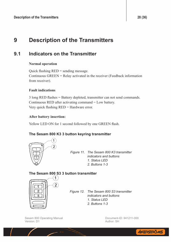
TheSesam800K33buttonkeyringtransmitter
1
2Figure11. TheSesam800K3transmitter indicatorsandbuttons 1.StatusLED 2.Buttons1-3
The Sesam 800 S3 3 button transmitter 1
2Figure12. The Sesam 800 S3 transmitter indicatorsandbuttons 1.StatusLED 2.Buttons1-3
Description of the Transmitters 29 (36)
Sesam 800 Operating Manual Document-ID: 941211-000Version: D1 Author: SH
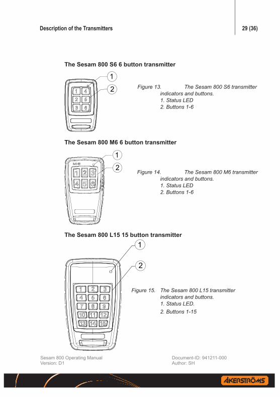
The Sesam 800 S6 6 button transmitter
1
2
Figure13. The Sesam 800 S6 transmitter indicatorsandbuttons. 1.StatusLED 2.Buttons1-6
The Sesam 800 M6 6 button transmitter
1
2Figure14. The Sesam 800 M6 transmitter indicatorsandbuttons. 1.StatusLED 2.Buttons1-6
The Sesam 800 L15 15 button transmitter1
2
Figure15. The Sesam 800 L15 transmitter indicatorsandbuttons. 1.StatusLED. 2.Buttons1-15
Replacing Batteries in the Transmitters 30 (36)
Sesam 800 Operating Manual Document-ID: 941211-000Version: D1 Author: SH
10 ReplacingBatteriesintheTransmitters
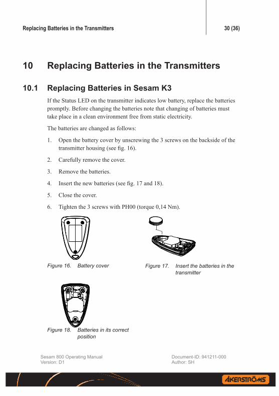
10.1 ReplacingBatteriesinSesamK3If the Status LED on the transmitter indicates low battery, replace the batteries promptly. Before changing the batteries note that changing of batteries must take place in a clean environment free from static electricity.
The batteries are changed as follows:
1. Open the battery cover by unscrewing the 3 screws on the backside of the transmitter housing (see fig. 16).
2. Carefully remove the cover.
3. Remove the batteries.
4. Insert the new batteries (see fig. 17 and 18).
5. Close the cover.
6. Tighten the 3 screws with PH00 (torque 0,14 Nm).
Figure16. Batterycover Figure17. Insert the batteries in the transmitter
Figure18. Batteries in its correct position

Replacing Batteries in the Transmitters 31 (36)
Sesam 800 Operating Manual Document-ID: 941211-000Version: D1 Author: SH
10.2 ReplacingBatteriesintheSesam800S3&S6
Figure19. Batterycoverandthescrewsholdingthe cover
Figure20. Batteries in the transmitter
Figure21. Back side of the cover inserted in its position.
If the Status LED on the transmitter in-dicates low battery, replace the batteries promptly. Before changing the batteries note that changing of batteries must take place in a clean environment free from static electricity.
The batteries are changed as follows:
1. Open the battery cover by unscrewing the 6 screws on the backside of the transmitter housing (see fig. 19).
2. Carefully remove the cover by lifting up the front of the cover (see fig. 21).
3. Insert the new batteries.
4. Close the cover by first inserting the backside of the cover in the transmitter, and then press the front down (see fig. 21).
5. Tighten the 6 screws with PH00 (torque 0,14 Nm).

Replacing Batteries in the Transmitters 32 (36)
Sesam 800 Operating Manual Document-ID: 941211-000Version: D1 Author: SH
10.3 ReplacingBatteriesinSesam800M6
Figure22. Batterycoverandthescrewsholdingthe cover
Figure23. Batteries in the transmitter
Figure24. Backside of the cover inserted in its position
If the Status LED on the transmitter indicates low battery, replace the batteries promptly. Before changing the batteries note that changing of batteries must take place in a clean environment free from static electricity.
The batteries are changed as follows:
1. Open the battery cover by unscrewing the 6 screws on the backside of the trans-mitter housing (see fig. 22).
2. Carefully remove the cover by lifting up the front of the cover (see fig. 24).
3. Remove the batteries.
4. Insert the new batteries.
5. Close the cover by first inserting the back-side of the cover in the transmitter, and then press the front down (see fig. 24).
6. Tighten the 6 screws with PH2 (torque 1 Nm)
Replacing Batteries in the Transmitters 33 (36)
Sesam 800 Operating Manual Document-ID: 941211-000Version: D1 Author: SH
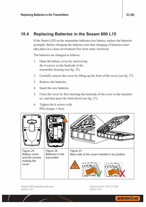
10.4 ReplacingBatteriesintheSesam800L15If the Status LED on the transmitter indicates low battery, replace the batteries promptly. Before changing the batteries note that changing of batteries must take place in a clean environment free from static electricity.
The batteries are changed as follows:
1. Open the battery cover by unscrewing the 6 screws on the backside of the transmitter housing (see fig. 25).
2. Carefully remove the cover by lifting up the front of the cover (see fig. 27).
3. Remove the batteries.
4. Insert the new batteries.
5. Close the cover by first inserting the backside of the cover in the transmit-ter, and then press the front down (see fig. 27).
6. Tighten the 6 screws with PH2 (torque 1 Nm).
Figure25. Batterycoverandthescrewsholdingthecover
Figure26. Batteries in the transmitter
Figure27. Back side of the cover inserted in its position

Error Codes 34 (36)
Sesam 800 Operating Manual Document-ID: 941211-000Version: D1 Author: SH
11 Error CodesThe Sesam 800 receivers can display a number of error codes. The error codes depends on the model of the receiver.
11.1 Error Codes, Sesam 800 RXDTabell 2. Error codes Sesam 800 RXD
Id already programmed. 1
Memory full. 2
Memory card mismatch during power- up. 10
Memory card write error. Possible memory card removal during operation.
11
Memory card copy to verify error. 12
Internal errors. The unit needs service. 3, 5 30, 31 and 32
Line power unstable. 4
11.2 Error Codes, Sesam 800 RX and RX DINAny of the above error states is displayed with ten quick flashes on the Status LED (LED 6) regardless of fault.

Receiver Drill Measure for RX and RXD 35 (36)
Sesam 800 Operating Manual Document-ID: 941211-000Version: D1 Author: SH
12 Receiver Drill Measure for RX and RXD
102-103,5 mm
102 mm
120 m
m
145 m
m
120 mm
225 mm
Figure28. Thereceivershallbeattachedwith4mmscrewsthataresuitableforthesurroundingenvironment
12.1 Measure for RX DIN
Figure29. TheDINreceivermeasure

ÅkerströmsBjörboABBox 7, SE-785 21 Gagnef, Swedenstreet Björbovägen 143SE-785 45 Björbo, SwedenPhone +46 241 250 00Fax +46 241 232 99E-mail [email protected]
©ÅkerströmsBjörboAB,2013


