.556.5 Pulling Vacuums .................................................................................. 62 7.0 NORMAL STARTUP .......................................................................................... 65 7.1 Normal Startup of LCO Hydrotreater .................................................................. 65 7.2 Startup Following a Major Turnaround ............................................................... 67 7.2.1 Pre-Start Check List ........................................................................................ 68 7.2.2 Unit Startup ................................................................................................... 69 7.3 Heater or Reboiler Startup ................................................................................. 73 7.4 Compressor Startup ........................................................................................... 74 7.5 Commissioning "D" Charge Pump ..................................................................... 75 8.0 SAFETY and HEALTH CONSIDERATIONS ...................................................... 77 8.1 Chemical Properties and Hazards ...................................................................... 77 8.2 Personal Protective Equipment and Precautions to Prevent Exposure . . . . . . . . . . . . . . . . . 78 8.3 Actions to be Taken if Physical Contact or Airborne Exposure Occur . . . . . . . . . . . . . . . . . . 79 8.4 Inventory and Quality Control of Hazardous Chemicals. . . . . . . . . . . . . . . . . . . . . 79 8.5 Special or Unique Hazards Associated With the Chemicals and or the Process . . . . . . . . . . . 79 8.6 Safety Systems and Their Functions . . . . . . . . 79 8.7 Safe Work Practices. . . . . . . . . . . . . . . . 79
KLM Technology Group
Operating Manuals
LIGHT CYCLE OIL HYDROTREATER
(OPERATING MANUALS )
Page 1 of 103 Rev: 01
Rev 01: MAY 2013
1
Introduction This operating manual is only a guide and reference for personnel connected with the operation and maintenance of the LCO Hydrotreater Unit. As such, this manual does not cover every step to be taken in ordinary operation of the unit. Some flow sheets and equipment specifications are furnished, in this manual, for ready reference. For details beyond those included, refer to mechanical specifications, manufacturers' data books and special instructions, technical books, etc. Throughout this manual, certain notes, cautions, and danger statements are provided. These statements will be used to clarify certain points of interest and to inform the unit personnel of any possible dangers associated with the operation of LCO Hydrotreater unit. 1.0 INITIAL STARTUP This section of the manual will incorporate information on the operation and installation of any future equipment installed in the LCO Hydrotreater area. This information will give the operators of the unit a background for understanding the equipment being installed. Along with operating instructions, Process and Information diagrams will be supplied to insure the operator's comprehension of the changes that are to be made.
KLM Technology Group
Operating Manuals
LIGHT CYCLE OIL HYDROTREATER
(OPERATING MANUALS )
Page 2 of 103 Rev: 01
Rev 01: MAY 2013
2
2.0 NORMAL OPERATIONS 2.1 LCO Hydrotreater Objective Hydrotreating is the process of hydrodesulfurization for improving the quality of Light Cycle Oil or Naptha by hydrogenation in the presence of catalyst. Goals of the LCO Hydrotreater unit are the: 1. Reduction of sulphur, nitrogen, and oxygen compounds. 2. Improvement of color, doctor, flash, and corrosion specifications. 3. Fabrication of a high quality finished Light Cycle Oil or Naphtha product. 2.1.1 LCO Hydrotreater Process Description The contaminant we will be concerned with primarily is sulphur. Sulphur compounds, in the form of mercaptans, sulfides, and disulfides will be converted to H2S. The contaminants are in the form where they can be easily removed from the oil by stripping fractionation and treating methods. The catalyst is relatively unaffected by most components of the charge stock which are known poisons to other catalytic refining processes such as Catalytic Reforming. The activity of the catalyst usually falls off by gradual deposition of coke upon it, rather than by metals contamination. The catalyst can be regenerated, off site, by burning of the coke. Hydrogenation liberates heat. In straight run stocks, very little heat is liberated because very little hydrogen is consumed. With cracked stocks, more heat is liberated because more hydrogen is consumed. LCO Hydrotreater runs a cracked stock from the FCC, and therefore requires considerably more hydrogen than the other Hydrotreaters. As mentioned above, the activity of the catalyst usually falls off by gradual deposition of coke upon it. With charge stock such as Light Cycle Oil or Naphtha, more coke may be laid down due to the higher operating temperatures necessary for the heavier stocks to obtain the needed sulfur conversion.
KLM Technology Group
Operating Manuals
LIGHT CYCLE OIL HYDROTREATER
(OPERATING MANUALS )
Page 3 of 103 Rev: 01
Rev 01: MAY 2013
3
LCO Hydrotreater is designed to remove sulfur compounds through the process of heat and reaction. This will be done in the Reactor of the unit. The Reactor section of the unit will be concerned with such elements as doctor, color, and sulfur. Natural gas is used on the Stripper tower to help remove corrosive gases from the product before it enters the Rerun tower. The Rerun tower separates the light hydrocarbons from the heavy hydrocarbons through a process of heating and cooling. The Rerun tower will be concerned with such elements as corrosion, flash, and distillation. The overhead product on the Rerun tower will be very corrosive in nature at this point in the process. Therefore, it is sent to a Caustic Scrubbing system before being sent to storage. There are two finished streams on LCO Hydrotreater. The bottoms stream is sent to a finished storage tank and blended with the finished #2 Oil. The overhead product is sent to a caustic treating system on the unit before being sent to storage.
KLM Technology Group
Operating Manuals
(OPERATING MANUALS
2.2 LCO Hydrotreater Flow Sequence The following flow sequence should be used in conjuction with the diagram in this section to better understand the process flow of the unit.
LIGHT CYCLE OIL HYDROTREATER
(OPERATING MANUALS )
Page
Rev: 01
Rev 01
4
Flow Sequence
The following flow sequence should be used in conjuction with the diagram in this section to better understand the process flow of the unit.
Page 4 of 103
Rev: 01
Rev 01: MAY 2013
The following flow sequence should be used in conjuction with the diagram in this section
KLM Technology Group
Operating Manuals
LIGHT CYCLE OIL HYDROTREATER
(OPERATING MANUALS )
Page 5 of 103 Rev: 01
Rev 01: MAY 2013
5
2.2.1 Reactor Section Flow Sequence Charge is taken from tanks into the suction of the charge pump. From the charge pump, the charge goes through the main charge control valve, before being split into two passes. The charge then flows through an "A" and "B" charge pass control valves where it is introduced with recycle hydrogen. The charge then enters the shell side of the two (2) sets of Reactor charge/Reactor effluent exchangers . From the outlet of these exchangers, in split passes, the charge enters the top of the Reactor heater. Leaving the bottom of the Reactor heater, the charge then enters the top of the Reactor in a single stream. From the bottom of the Reactor, the charge then enters the tube side of the Reactor charge/Reactor effluent exchangers in split streams again. The charge, back into a single stream, then flows through a single Stripper charge/Reactor effluent exchanger From this exchanger, the product enters the Product Separator fin fans. From the bottom of the fin fans, the product then flows through a single product cooler before entering the top of the Product Separator. The level in the separator is controlled with a liquid level control valve. The pressure on the Separator is controlled by way of an off gas line flowing to the Amine unit. Sour water is removed from the bottom of the separator . 2.2.2 Stripper Tower Flow Sequence Once the product leaves the bottom of the Product Separator, it will flow through the shell side of the Stripper charge/Reactor effluent exchanger before entering the top of the Stripper tower. Natural gas is added to the stripper tower. The Stripper tower bottoms is the charge to the Rerun tower. The off gas on the Stripper tower flows through a knock out drum before being sent to the Amine unit. 2.2.3 Rerun Tower Flow Sequence As the charge leaves the Stripper tower, it will flow through the Rerun charge/Rerun bottoms exchanger on the shell side. Leaving the top of these exchangers, the charge enters the Rerun tower. The Rerun bottoms pump will take suction from the bottom of the tower. From the discharge of the pump, the Rerun bottoms circulation will split into
KLM Technology Group
Operating Manuals
LIGHT CYCLE OIL HYDROTREATER
(OPERATING MANUALS )
Page 6 of 103 Rev: 01
Rev 01: MAY 2013
6
two streams. One stream will flow back through the shell side of the Rerun charge/ Rerun bottoms exchanger. Leaving these exchangers, the product will flow through two product coolers before leaving the unit by way of the Rerun bottoms control valve. The bottoms will be sent to storage tanks. The other stream off of the circulation line will split into two streams before entering the Rerun reboiler. Leaving the Rerun reboiler, the circulation stream will flow back into one line before going back into the tower. Through the heated circulation in the tower, light hydrocarbons will flow out the top of the tower through an overhead fin fan cooler. From there, the overhead product will flow into the overhead receiver. The Rerun overhead pump will take suction from the receiver and split into two streams. The Reflux stream will be sent back into the top of the tower to control the top temperature. The overhead to storage stream will be sent to the Caustic Settler for additional treatment. The pressure on the Rerun tower will be controlled by an off gas line off the top of the overhead receiver. The off gas will be sent to the suction of the Sat Gas compressor at the Crude unit or to the flare with the use of the back pressure controller. 2.2.4 Caustic Settler Flow Sequence There are two flows at the Caustic Settler: a Caustic flow and a Rerun overhead flow. The Caustic circulation pump will take suction from the bottom of the Caustic Settler and send the caustic through a control valve to mix with the Rerun overhead. The Rerun overhead will enter the unit just past the caustic control valve. Both streams will then enter the Caustic Mixer before entering the top of the Caustic Settler. In the Settler, the caustic will settle to the bottom, and the Rerun overhead will flow out the top of the Settler into the top of the Sand Filter. From the bottom of the Sand Filter, the Rerun overhead to storage will be sent to tankage.
KLM Technology Group
Operating Manuals
LIGHT CYCLE OIL HYDROTREATER
(OPERATING MANUALS )
Page 7 of 103 Rev: 01
Rev 01: MAY 2013
7
2.2.5 V.G.O. Flow Sequence The V.G.O. flow, like the charge flow, will take suction from tanks. The V.G.O. pump can send the charge four different ways. First, the charge can be sent into the suction of the charge pump (though this is rarely done). Second, the charge can be sent to the Rerun charge control valve. Third, it can be sent to Gas Oil Hydrotreater suction. Finally, it can be sent to storage as a means of transferring product. When product is transferred to storage, it will be sent to the downstream side of the rerun bottoms control valve. It can also be sent through the cutter stock control valve tankage. 2.2.6 Fresh and Recycle Hydrogen Flow Like the other Hydrotreaters, there are two hydrogen flows on LCO Hydrotreater: A makeup or fresh hydrogen flow and a recycle flow. The makeup flows from the Unifiner manifold and enters the makeup drum. From the top of this drum, the hydrogen flows into the top of #1 and #2 compressor makeup suction and is pumped out the bottom of both compressors through the makeup discharge into a G-Fin cooler. From the G-Fin cooler, the hydrogen enters a knockout drum. From where the fresh hydrogen enters the makeup drum, a line comes off this line through a back pressure control valve and also enters the knockout drum. Hydrogen is taken off this line and sent through a control valve and sends makeup hydrogen to the top of the Separator fin fans. Here it is introduced with the Reactor charge. The recycle gas stream takes suction off the top of the Separator and flows through #1 and #2 compressor recycle suction. It is pumped out the recycle discharge and is, in separate streams, introduced with the charge before the Reactor charge/Reactor effluent exchangers. 2.2.7 Condensate Injection Although various sources supply the condensate on LCO Hydrotreater, the majority comes from the service condensers. These sources flow into the top of the condensate receiver. From the bottom of the receiver, the condensate flows through a control valve and into a G-fin cooler where it is cooled with water. From the outlet of the cooler, the condensate flows into the suction of the condensate injection pump. From the discharge of the pump, the condensate can flow into the top of the separator condensers and/or to
KLM Technology Group
Operating Manuals
LIGHT CYCLE OIL HYDROTREATER
(OPERATING MANUALS )
Page 8 of 103 Rev: 01
Rev 01: MAY 2013
8
the charge side of the Reactor charge/Reactor effluent exchangers. All remaining water is removed from the bottom of the separator water boot. 2.4 Operating Conditions 2.4.1 Reactor Section Operating Conditions As mentioned in the Process Description, LCO Hydrotreater will be concerned with the removal of sulfur and other contaminants. The type of catalyst used on LCO Hydrotreater is different from that of the Catalytic Reformer. It is designed to remove sulfur compounds which are known poisons to the Catalytic Reformer Reactors. LCO Hydrotreater has a capacity of approximately 8,600 B/D through the reactor section of the unit. The unit employs one reactor. LCO Hydrotreater, unlike the other Hydrotreaters, employs a stripper section after the Reactor section (discussed in the next section). The stripper section helps to strip the corrosive gases or light ends with the use of natural gas. A Rerun tower is also used to remove the light ends and finalize the product prior to sending the product ot storage. The following is a guide of parameter ranges along with optimal conditions for the operation of the LCO Hydrotreater Reactor section. Though these parameters may vary from their stated ranges, due to charge stock changes or specific operating conditions, they are considered good operational control.
KLM Technology Group
Operating Manuals
LIGHT CYCLE OIL HYDROTREATER
(OPERATING MANUALS )
Page 9 of 103 Rev: 01
Rev 01: MAY 2013
9
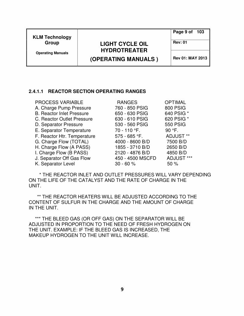
2.4.1.1 REACTOR SECTION OPERATING RANGES PROCESS VARIABLE RANGES OPTIMAL A. Charge Pump Pressure 760 - 850 PSIG 800 PSIG B. Reactor Inlet Pressure 650 - 630 PSIG 640 PSIG * C. Reactor Outlet Pressure 630 - 610 PSIG 620 PSIG * D. Separator Pressure 530 - 560 PSIG 550 PSIG
E. Separator Temperature 70 - 110 °F. 90 °F.
F. Reactor Htr. Temperature 575 - 685 °F. ADJUST ** G. Charge Flow (TOTAL) 4000 - 8600 B/D 7500 B/D H. Charge Flow (A PASS) 1855 - 3710 B/D 2650 B/D I. Charge Flow (B PASS) 2120 - 4876 B/D 4850 B/D J. Separator Off Gas Flow 450 - 4500 MSCFD ADJUST *** K. Separator Level 30 - 60 % 50 % * THE REACTOR INLET AND OUTLET PRESSURES WILL VARY DEPENDING ON THE LIFE OF THE CATALYST AND THE RATE OF CHARGE IN THE UNIT. ** THE REACTOR HEATERS WILL BE ADJUSTED ACCORDING TO THE CONTENT OF SULFUR IN THE CHARGE AND THE AMOUNT OF CHARGE IN THE UNIT. *** THE BLEED GAS (OR OFF GAS) ON THE SEPARATOR WILL BE ADJUSTED IN PROPORTION TO THE NEED OF FRESH HYDROGEN ON THE UNIT. EXAMPLE: IF THE BLEED GAS IS INCREASED, THE MAKEUP HYDROGEN TO THE UNIT WILL INCREASE.