12
OPERATING INSTRUCTION Conversion instructions FOR DX30/60 TO DX35/50 UPGRADE KIT

O p e r a t i n g i n s t r u c t i O n
Conversion instructions for DX30/60 to DX35/50 UpgraDe Kit

Instructions for DX30/60 to DX35/50 Upgrade Kit Record the current sensor type
2 8017183/2014-03-18
1 Correct use The “DX30/60 to DX35/50 Upgrade Kit” is designed for carrying out the conversion from the previously used DS60 or DS40 distance sensor to the current DS35 or DS50 distance sensor with the lowest possible cost and effort. The SICK upgrade kit contains all the accessories required for mechanically mounting the DS35 or DS50 with the help of an adapter plate on the existing DS40 or DS60 drill pattern. Once you have the required DS35 or DS50 distance sensor you can start with the conversion.
2 Safety information • Before performing any work with the distance sensor, read this conversion instruction • The available operating instructions for DS35 or DS50 must also be observed. These can be found
on the product pages on our website (www.mysick.com/en/ds35 or www.mysick.com/en/ds50) • Do not stare into the laser beam. • Connection, mounting and setting must be performed by qualified personnel. • Lines must only be established and disconnected with the supply voltage switched off. • Conducting cross sections of the supply cable from the customer's power system should be
designed in accordance with the applicable standards. • No safety component pursuant to EU machinery directive.
3 Carrying out the conversion
3.1. Record the current sensor type 1. Identify the currently used sensor and write down type code and order number. This is important to
choose the correct replacement type (see also chapter 3.3.) and set up the replacement device correctly. Sensor type: __________________________ Order number: __________
3.2. Record the current settings For DS60 and DS40 1. Check the position of the switching point and the behavior for output Q1 and write this down:
Switching point at: __________ mm □ Q (active-high) □ Q not (active-low)
For DS60 2. Check the position of the switching point and the behavior for output Q2 and write this down:
Switching point at: __________ mm □ Q (active-high) □ Q not (active-low) Remark: Please consider that the on and off switching point are different due to the hysteresis of the switching output. In order to allow an easy alignment of the future sensor later on, please mark the position of the light spot of the current sensor. This may for example be done by use of a pen, an adhesive tape or a reference object depending on the application environment you are facing.

Instructions for DX30/60 to DX35/50 Upgrade Kit
Choose the correct replacement model
8017183/2014-03-18 3
3.3. Choose the correct replacement model Look for the type code of the sensor you are currently using and identify the correct replacement product. For an easy conversion please mark the relevant steps of conversion:
3.4. Remove the DS40 or DS60 distance sensor 1. Switch off the system as well as the power supply of the sensor and assure that it can not be
switched on again accidentally. 2. Disconnect the cable from the sensor. 3. Dismount and remove the sensor from its base and put the screws and nuts in a safe place in case
you may need those later on. 4. Store the DS40 or DS60 distance sensors or properly dispose the ones which are no longer
needed.
3.5. Mount the DS35 or DS50 Mount the plate on the existing drill pattern and the DS35 or DS50 on the adapter plate.

Instructions for DX30/60 to DX35/50 Upgrade Kit Electrical connection
4 8017183/2014-03-18
3.6. Electrical connection Electrical connection with existing 5-pin cable: The existing cable from the PLC to the sensor can also be used for the connection of DS35 or DS50. PLC
Existing cable DS35 or DS50 From PLC to sensor
Electrical connection with existing 4-pin cable: In case the existing cable does not provide the 5th pin hole either the existing cable has to be replaced by a M12 5 pin cable or an adapter cable is needed in order to be able to connect the DS35 or DS50. An adapter cable from 4-pin to 5-pin is offered by SICK as an accessory. This adapter cable is available with the order number 6053730.
PLC
Existing cable adapter cable 4-pin to 5-pin DS35 or DS50 From PLC to sensor
In case the cables are not fully stores, please fasten the cables with cable ties.
3.7. Alignment of the sensor Depending on the conversion process recommended for the product you are replacing, please follow one of the options described below:
a. Alignment of red light version
Align red light spot to desired detection or measurement position.
b. Align infrared light version of DS35 1. Position object 2. Attach a small reflective tape to the center of the object for performing alignment. → See the
figure below. For a simpler alignment, you can also first use the reflective stripe (provided with this upgrade kit) in the horizontal direction and then in the vertical direction.
3. Change the distance sensor to alignment mode. To do this, in run mode, press and hold the set pushbutton for longer than 5 seconds.
4. Align the distance sensor roughly in the direction of the reflective tape. 5. Perform fine adjustment. Align the distance sensor such that the highest possible alignment
quality is indicated. The alignment quality is indicated as follows: - Using the vertically arranged LEDs Q1 near to slow … fast: The greater the number of LEDs that light up, the better the alignment quality. - using the LEDs Q1 and Q2: The faster both LEDs flash, the better the alignment quality. Slow flashing at approx. 1 Hz corresponds to poor alignment quality (no reflective tape). Rapid flashing at approx. 15 Hz corresponds to high alignment quality (highest reflective level).
6. In order to leave alignment mode, either press and hold the set pushbutton longer than 5 seconds or wait 5 minutes without pressing the pushbuttons.
7. Remove the small reflective tape used for alignment from the object.

Instructions for DX30/60 to DX35/50 Upgrade Kit
Check light spot geometry
8017183/2014-03-18 5
3.8. Check light spot geometry Due to the fact that the light spot geometries of DS35 or DS50 may be different to the previously used DS60 or DS40, please check the light spot size and geometry for its application capabilities. Please optimize the alignment of the new sensor according to the new light spot geometry in order to solve your application best. In case the application can not be solved with the new sensor, please get in contact with your sales representative to select an alternative sensor according to your specific needs.
3.9. Prepare application environment Depending on the conversion process recommended for the product you are replacing, please follow one of the options described below: a. Make available an object for detection
Make an object available if needed for the configuration of the sensor later on.
b. Install background or reference surface. Install a reference surface if needed for the configuration of the sensor later on.
c. Apply reflector on the measured object For sensors requiring a reflector, please attach a large reflective tape on the object to be measured or detected. Ensure that the reflective tape is arranged in a way that no direct reflections affect the sensor. In order to do so, the reflector should be tilted by approx. 1° ... 3° as shown in the figure below.

Instructions for DX30/60 to DX35/50 Upgrade Kit Check required measuring range, response time and repeatability
6 8017183/2014-03-18
4 Configuring the DS35 In case the DS35 is used as replacement product the configuration of the sensor is described in the following chapters. In case the DS50 is used for the replacement of the old sensor this section can be skipped and you can proceed starting from chapter 5.
4.1. Check required measuring range, response time and repeatability For the replacement of some sensors it is recommended to adjust the measurement speed of the DS35 distance sensor. If it is recommended to adjust the speed in case of your replacement, please follow the described option below. For all other user the adjustable speed of the DS35 is an additional option to solve your application even better than before. The selected measurement speed of the DS35 will affect range and repeatability. In order to achieve a wider range and better repeatability the speed can be reduced. At a loss of range and repeatability the speed can be increased which will result in a faster response time of the sensor. In case one of the previous options is desired you may also choose one of the following options.
a. Increase measurement speed of the DS35
1. Press and hold the select pushbutton for longer than 5 seconds. The Q1 near LED lights up.
2. Press repeatedly the select pushbutton until the LED slow… fast flashes. 3. Press repeatedly the set pushbutton until the desired speed has been set to medium, fast
or super fast: • LED slow … fast flashes cyclically 2 x: slow (factory setting) • LED slow … fast flashes cyclically 3 x: medium • LED slow … fast flashes cyclically 4 x: fast • LED slow … fast flashes cyclically 5 x: super-fast
4. In order to leave the teach mode, either press and hold the select pushbutton for more than 5 seconds or wait 5 minutes without pressing the pushbuttons.
b. Reduce measurement speed of the DS35 1. Press and hold the select pushbutton for longer than 5 seconds. The Q1 near LED lights
up. 2. Press repeatedly the select pushbutton until the LED slow… fast flashes. 3. Press repeatedly the set pushbutton until the desired speed has been set to super-slow
• LED slow … fast flashes cyclically 1 x: super-slow • LED slow … fast flashes cyclically 2 x: slow (factory setting)
4. In order to leave teach mode, either press and hold the select pushbutton for more than 5 seconds or wait 5 minutes without pressing the pushbuttons.
4.2. Set up the outputs Depending on the conversion process recommended for the product you are replacing, please follow one of the options described below:
a. Teach in Q1 and/or Q2 in Distance to Object (DtO) mode
Option A: In case the output behavior of the previously used sensor was active-high (Q) please follow this description. Otherwise, please proceed with Option A.
1 Teach point
1. Position object at teach point 2. Press and hold the select pushbutton for longer than 5 seconds. Q1 near LED lights up.

Instructions for DX30/60 to DX35/50 Upgrade Kit
Set up the outputs
8017183/2014-03-18 7
3. To teach in the switching point For Q1: Press the set pushbutton. For Q2: Repeatedly press the select pushbutton until the Q2 near LED lights up. Press the set pushbutton.
4. If the teach was successful Q1 and Q2 LEDs flash twice simultaneously. If the teach was not successful, the Q1 and Q2 LEDs flash alternately.
5. If fine teach is necessary please refer to the operating instructions of DS35 6. In order to leave teach mode, either press and hold the select pushbutton longer than 5
seconds or wait 5 minutes without pressing the pushbuttons.
Option B: In case the output behavior of the previously used sensor was active-low (Q not) please follow this description. Otherwise, please proceed with Option A.
1 Teach point
1. Position object at teach point 2. Press and hold the select pushbutton for longer than 5 seconds. Q1 near LED lights up. 3. To teach in the switching point:
For Q1: Press the select pushbutton. The Q1 far LED lights up. Press the set pushbutton. For Q2: Repeatedly press the select pushbutton until the Q2 far LED lights up. Press the set pushbutton.
4. If the teach was successful Q1 and Q2 LEDs flash twice simultaneously. If the teach was not successful, the Q1 and Q2 LEDs flash alternately.
5. If fine teach is necessary please refer to the operating instructions of DS35 6. In order to leave teach mode, either press and hold the select pushbutton longer than 5
seconds or wait 5 minutes without pressing the pushbuttons.
b. Teach in Q1 and/or Q2 in Object between Sensor and Background (ObSB) mode In case of the ObSB mode the output is activated when objects are detected that differ from the background. The tolerance range around the taught-in background is ± 25 mm plus a hysteresis of 25 mm. The hysteresis can be configured only via IO-Link.
1 Teach point 2 Tolerance around teach point: ± 25 mm
1. Align distance sensor on background (teach point 1). 2. Press and hold the select pushbutton for longer than 5 seconds. Q1 near LED lights up. 3. To teach in the switching point
For Q1: Repeatedly press the select pushbutton until Q1 near and Q1 far (ObSB) LEDs light up. Press the set pushbutton. For Q2: Repeatedly press the select pushbutton until Q1 near and Q1 far (ObSB) LEDs light up.

Instructions for DX30/60 to DX35/50 Upgrade Kit Set up the multifunctional input
8 8017183/2014-03-18
Press the set pushbutton. 4. If the teach was successful Q1 and Q2 LEDs flash twice simultaneously. If the teach was not
successful, the Q1 and Q2 LEDs flash alternately. 5. If fine teach is necessary please refer to the operating instructions of DS35 6. In order to leave teach mode, either press and hold the select pushbutton longer than 5
seconds or wait 5 minutes without pressing the pushbuttons.
Remark: For DS35 no ObSB mode with an active-low (Q not) output behavior is available for teach in. In case this is needed please use DS50 instead or use IO-Link for the setup of the sensor.
4.3. Set up the multifunctional input Depending on the conversion process recommended for the product you are replacing, please follow one of the options described below:
a. Do not use or deactivate the multifunctional (MF) input
For DS60 and DS40 in most cases no multifunctional input was available. Therefore it needs to be assured that no signals are applied to pin 5 of the DS35 in order to avoid that a teach is carried out accidentally. If this is not possible the multifunctional input needs to be deactivated as described in the following: 1. Press and hold select and set pushbuttons simultaneously in the run mode for longer than 10
seconds. The Q1 near LED lights up and the LED slow … fast flashes cyclically according to the actual setting.
2. Repeatedly press the set pushbutton until the LED slow … fast cyclically flashes three times: • LED slow … fast flashes 1 x: external teach (default setting) • LED slow … fast flashes 3 x: multifunctional input MF inactive.
3. To leave the expert mode, press and hold the select and set pushbuttons simultaneously for longer than 10 seconds or wait 5 minutes without pressing the pushbuttons.
b. Set the function of the multifunctional input to laser off
In case the multifunctional input is required to directly switch off the laser whenever a signal is applied to pin 5 of the DS35 the steps described below have to be followed: 1. Press and hold select and set pushbuttons simultaneously in the run mode for longer than 10
seconds. The Q1 near LED lights up and the LED slow … fast flashes cyclically according to the actual setting.
2. Repeatedly press the set pushbutton until the LED slow … fast cyclically flashes twice: • LED slow … fast flashes 1 x: external teach (default setting) • LED slow … fast flashes 2 x: laser off
3. To leave expert mode, press and hold the select and set pushbuttons simultaneously for longer than 10 seconds or wait 5 minutes without pressing the pushbuttons.
c. Use the multifunctional input for external teach
In case the multifunctional input is used for the external teach no settings have to be changed, as this is the default setting of the Dx35. Therefore, please check which teach functions are used and adjust the settings in the PLC according to the timing of the DS35 as shown in the following table:
The timing tolerance for the two "Move last teach point" functions is ± 20 ms. For all other teach functions the timing tolerance is ± 30 ms.
Teach function Time Move last teach point + 10 mm 60 ms Move last teach point - 10 mm 120 ms Switch off laser 200 ms Switch on laser 300 ms Teach in active-high behavior for Q1 distance to object 400 ms Teach in active-low behavior for Q1 distance to object 500 ms Teach in Q1 object between sensor and background 800 ms Teach in active-high behavior for Q2 distance to object 1000 ms
Instructions for DX30/60 to DX35/50 Upgrade Kit
Additional settings or possibilities
8017183/2014-03-18 9
Teach in active-low behavior for Q2 distance to object 1100 ms Teach in Q2 object between sensor and background 1400 ms Laser off > 3000 ms
For more information regarding the external teach functionality of DS35 incl. additional teach options, please refer to the operating instructions of the sensor.
4.4. Additional settings or possibilities The DS35 offers a much wider range of settings and possibilities than the DS60 or DS40. This may allow solving applications in an easier or better way than in the past. For more details regarding these additional features and settings, please refer to the operating instructions of your new DS35 sensor.
5 Configuring the DS50 In case the DS50 is used as replacement product the configuration of the sensor is described in the following chapters. In case the DS35 is used for the replacement of the old sensor please refer to chapter 4 instead.
5.1. Check required response time and repeatability For the replacement of some sensors it is recommended to adjust the averaging setting of the DS50 distance sensor. If it is recommended to adjust the averaging in case of your replacement, please follow the described option below. Otherwise you can skip the next step.
a. Increase measurement speed of the DS35
1. In run-mode press the set-pushbutton for less than 1 second. Menu will be displayed in the set-mode.
2. Press the set-pushbutton. Mode will be displayed in the men-mode. 3. Repeatedly press the down pushbutton until Averag is displayed. Press the set-pushbutton.
Choose Fast by pressing the down-pushbutton and confirm setting by pressing the set-pushbutton.
4. In order to leave the set-mode press the esc-pushbutton repeatedly until the run-mode is shown again.
5.2. Set up the outputs Depending on the conversion process recommended for the product you are replacing, please follow one of the options described below:
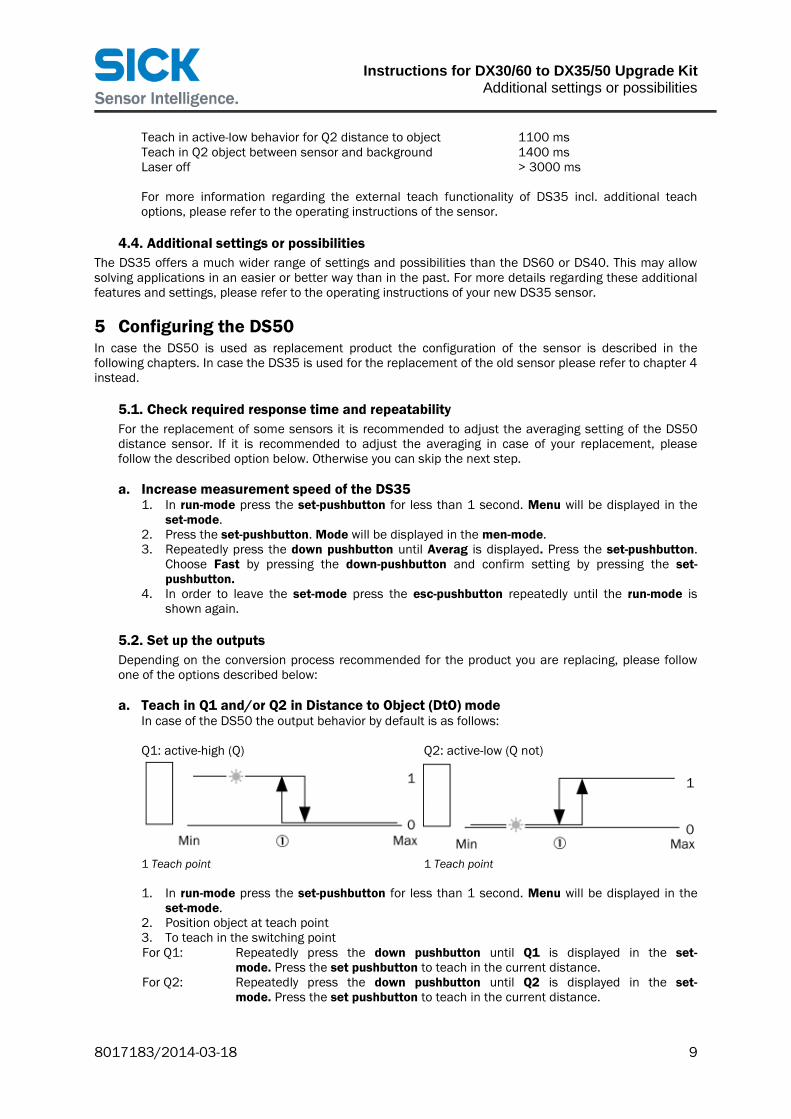
a. Teach in Q1 and/or Q2 in Distance to Object (DtO) mode
In case of the DS50 the output behavior by default is as follows: Q1: active-high (Q) Q2: active-low (Q not)
1 Teach point 1 Teach point
1. In run-mode press the set-pushbutton for less than 1 second. Menu will be displayed in the
set-mode. 2. Position object at teach point 3. To teach in the switching point For Q1: Repeatedly press the down pushbutton until Q1 is displayed in the set- mode. Press the set pushbutton to teach in the current distance. For Q2: Repeatedly press the down pushbutton until Q2 is displayed in the set- mode. Press the set pushbutton to teach in the current distance.

Instructions for DX30/60 to DX35/50 Upgrade Kit Optional: Change the output behavior of DS50
10 8017183/2014-03-18
4. If the teach was successful Q1 and Q2 LEDs flash twice simultaneously. If the teach was not successful, the Q1 and Q2 LEDs flash alternately.
5. If the switching point needs to be adjusted manually please refer to the operating instructions of DS50
6. In order to leave the set-mode press the esc-pushbutton.
Remark: In case your application requires a different output behavior, please change the behavior as described in chapter “5.3 Optional: Change the output behavior of DS50”.
b. Teach in Q1 and/or Q2 in Object between Sensor and Background (ObSB) mode In case of the DS50 the output behavior by default is as follows: Q1: active-high (Q) Q2: active-low (Q not)
1 Teach point 1 Teach point 2 Tolerance around teach point: ± 25 mm 2 Tolerance around teach point: ± 25 mm
1. In run-mode press the set-pushbutton for less than 1 second. Menu will be displayed in the set-
mode. 2. Press the down-pushbutton. Mode with be displayed in the set-mode 3. Press the set-pushbutton. Choose ObSB by pressing the down-pushbutton and confirm setting by
pressing the set-pushbutton. 4. Position reference background to be taught in. 5. To teach in the background:
For Q1: Press the down pushbutton. Q1 is displayed in the set-mode. Press the set pushbutton to teach in the current background. For Q2: Repeatedly press the down pushbutton until Q2 is displayed in the set- mode. Press the set pushbutton to teach in the current background.
6. If the teach was successful Q1 and Q2 LEDs flash twice simultaneously. If the teach was not successful, the Q1 and Q2 LEDs flash alternately.
7. If the switching point needs to be adjusted manually please refer to the operating instructions of DS50
8. In order to leave the set-mode press the esc-pushbutton.
Remark: In case your application requires a different output behavior, please change the behavior as described in chapter “5.3 Optional: Change the output behavior of DS50”.
5.3. Optional: Change the output behavior of DS50 In case your application requires a different output behavior, the behavior can be changed as described in the following: 1. In run-mode press the set-pushbutton for less than 1 second. Menu will be displayed in the set-
mode. 2. Press the set-pushbutton. Mode will be displayed in the men-mode. 3. To invert the switching behavior:
For Q1: Repeatedly press the down pushbutton until Q1Log is displayed. Press the set-pushbutton. Choose /Q by pressing the down-pushbutton and confirm setting by pressing the set-pushbutton. For Q2: Repeatedly press the down pushbutton until Q2Log is displayed. Press the set-pushbutton. Choose Q by pressing the down-pushbutton and confirm setting by pressing the set-pushbutton.

Instructions for DX30/60 to DX35/50 Upgrade Kit
Set up the multifunctional input
8017183/2014-03-18 11
4. In order to leave the set-mode press the esc-pushbutton repeatedly until the run-mode is shown again.
5.4. Set up the multifunctional input Depending on the conversion process recommended for the product you are replacing, please follow one of the options described below: a. Do not use or deactivate the multifunctional (MF) input
For DS60 and DS40 in most cases no multifunctional input was available. Therefore it needs to be assured that no signals are applied to pin 5 of the DS50 in order to avoid that the laser is switched off accidentally. If this is not possible the multifunctional input needs to be deactivated as described in the following: 1. In run-mode press the set-pushbutton for less than 1 second. Menu will be displayed in the
set-mode. 2. Press the set-pushbutton. Mode will be displayed in the men-mode. 3. Repeatedly press the down pushbutton until MF is displayed. Press the set-pushbutton.
Choose MF-Off by repeatedly pressing the down-pushbutton and confirm the setting by pressing the set-pushbutton.
4. In order to leave the set-mode press the esc-pushbutton repeatedly until the run-mode is shown again.
b. Use laser off function for MF (multifunctional input)
In case the multifunctional input is used to directly switch off the laser whenever a signal is applied to pin 5 no settings have to be changed, as this is the default setting of the DS50. Therefore it only has to be checked that the signal levels are set up in the PLC accordingly.
c. Choose external teach functionality and adjust PLC accordingly
In case the multifunctional input is required for the external teach functionality the steps described below have to be followed: 1. In run-mode press the set-pushbutton for less than 1 second. Menu will be displayed in the
set-mode. 2. Press the set-pushbutton. Mode will be displayed in the men-mode. 3. Repeatedly press the down pushbutton until MF is displayed. Press the set-pushbutton.
Choose Teach by pressing the down-pushbutton and confirm the setting by pressing the set-pushbutton.
4. In order to leave the men-mode press the esc-pushbutton repeatedly until the run-mode is shown again.
After that, please check which teach functions are used and adjust the settings in the PLC according to the timing of the DS50 as shown in the following table:
The timing tolerance is ± 30 ms for all teach functions. Teach function Time Teach in active-high behavior for Q1: 100 ms Teach in active-low behavior for Q1: 300 ms Teach in active-high behavior for Q2: 500 ms Teach in active-low behavior for Q2: 700 ms Laser Off: > 1500 ms For more information regarding the external teach functionality of DS50 incl. additional teach options, please refer to the operating instructions of the sensor.
5.5. Additional settings or possibilities The DS50 offers a much wider range of settings and possibilities than the DS60 or DS40. This may allow solving applications in an easier or better way than in the past. For more details regarding these additional features and settings, please refer to the operating instructions of your new DS50 sensor.

SICK AG | Waldkirch | Germany | www.sick.com
8017
183/
2014
-03-
18 ∙
NP_
8M (2
014-
03) ∙
A4
4c in
t42
AustraliaPhone +61 3 9457 0600 1800 334 802 – tollfreeE-Mail [email protected]
Belgium/LuxembourgPhone +32 (0)2 466 55 66E-Mail [email protected]
BrasilPhone +55 11 3215-4900E-Mail [email protected]
CanadaPhone +1 905 771 14 44E-Mail [email protected]
Česká republikaPhone +420 2 57 91 18 50E-Mail [email protected]
ChinaPhone +86 4000 121 000E-Mail [email protected] +852-2153 6300E-Mail [email protected]
DanmarkPhone +45 45 82 64 00E-Mail [email protected]
DeutschlandPhone +49 211 5301-301E-Mail [email protected]
EspañaPhone +34 93 480 31 00E-Mail [email protected]
FrancePhone +33 1 64 62 35 00E-Mail [email protected]
Great BritainPhone +44 (0)1727 831121E-Mail [email protected]
IndiaPhone +91–22–4033 8333E-Mail [email protected]
IsraelPhone +972-4-6881000E-Mail [email protected]
ItaliaPhone +39 02 27 43 41E-Mail [email protected]
JapanPhone +81 (0)3 3358 1341E-Mail [email protected]
MagyarországPhone +36 1 371 2680E-Mail [email protected]
NederlandPhone +31 (0)30 229 25 44E-Mail [email protected]
Norge Phone +47 67 81 50 00E-Mail [email protected]
ÖsterreichPhone +43 (0)22 36 62 28 8-0E-Mail [email protected]
PolskaPhone +48 22 837 40 50E-Mail [email protected]
RomâniaPhone +40 356 171 120 E-Mail [email protected]
RussiaPhone +7-495-775-05-30E-Mail [email protected]
SchweizPhone +41 41 619 29 39E-Mail [email protected]
SingaporePhone +65 6744 3732E-Mail [email protected]
SlovenijaPhone +386 (0)1-47 69 990E-Mail [email protected]
South AfricaPhone +27 11 472 3733E-Mail [email protected]
South KoreaPhone +82 2 786 6321/4E-Mail [email protected]
SuomiPhone +358-9-25 15 800E-Mail [email protected]
SverigePhone +46 10 110 10 00E-Mail [email protected]
TaiwanPhone +886 2 2375-6288E-Mail [email protected]
TürkiyePhone +90 (216) 528 50 00E-Mail [email protected]
United Arab EmiratesPhone +971 (0) 4 88 65 878E-Mail [email protected]
USA/MéxicoPhone +1(952) 941-6780 1 (800) 325-7425 – tollfreeE-Mail [email protected]
More representatives and agencies at www.sick.com


