18
Operating principle Bolero XL (2008)

Operating principle
Bolero XL (2008)

All rights reserved.
No part of this document may be copied and/or published by means of printing, photocopying,microfilming or by any other means whatsoever without the prior written consent of the manufacturer.This applies equally to the included drawings and/or diagrams.
The information contained in this document is based on general data concerning the construction, materialscharacteristics and working methods known to us at the time of publication and therefore we reserve the rightto make changes without notice. For this reason the instructions contained in this document should betreated as a guide to the installation, maintenance and repair, of the machine indicated on the front cover.
This document applies to the standard version of this machine. The manufacturer therefore accepts noliability for any damage arising from specifications that deviate from the standard version of the machineas delivered to you.
Every possible care has been taken in the production of this document, but the manufacturer accepts noliability for any errors in this document or for any consequences arising therefrom.
Table of contents
III�Copyright Bravilor Bonamat BV
1. OPERATING PRINCIPLE 1. . . . . . . . . . . . . . . . . . . . . . . . . . . . . . . . . . . . . . . . . . 1.1 General operation 1. . . . . . . . . . . . . . . . . . . . . . . . . . . . . . . . . . . . . . . . . . . . . . . . . 1.2 Water dosing system 2. . . . . . . . . . . . . . . . . . . . . . . . . . . . . . . . . . . . . . . . . . . . . .
1.2.1 Initialisation 3. . . . . . . . . . . . . . . . . . . . . . . . . . . . . . . . . . . . . . . . . . . . . . . . . . . . . . . . 1.2.2 Filling 3. . . . . . . . . . . . . . . . . . . . . . . . . . . . . . . . . . . . . . . . . . . . . . . . . . . . . . . . . . . . . 1.2.3 Heating 3. . . . . . . . . . . . . . . . . . . . . . . . . . . . . . . . . . . . . . . . . . . . . . . . . . . . . . . . . . . . 1.2.4 Dosing 4. . . . . . . . . . . . . . . . . . . . . . . . . . . . . . . . . . . . . . . . . . . . . . . . . . . . . . . . . . . .
1.3 Powder dosing system 6. . . . . . . . . . . . . . . . . . . . . . . . . . . . . . . . . . . . . . . . . . . . 1.4 Mixing system 7. . . . . . . . . . . . . . . . . . . . . . . . . . . . . . . . . . . . . . . . . . . . . . . . . . . . 1.5 Ventilation system 7. . . . . . . . . . . . . . . . . . . . . . . . . . . . . . . . . . . . . . . . . . . . . . . . 1.6 Operating system 8. . . . . . . . . . . . . . . . . . . . . . . . . . . . . . . . . . . . . . . . . . . . . . . . .
1.6.1 Keyboard 8. . . . . . . . . . . . . . . . . . . . . . . . . . . . . . . . . . . . . . . . . . . . . . . . . . . . . . . . . . 1.6.2 Main board 8. . . . . . . . . . . . . . . . . . . . . . . . . . . . . . . . . . . . . . . . . . . . . . . . . . . . . . . . .
1.7 Hardware protections 9. . . . . . . . . . . . . . . . . . . . . . . . . . . . . . . . . . . . . . . . . . . . . 1.7.1 Overflow protection 9. . . . . . . . . . . . . . . . . . . . . . . . . . . . . . . . . . . . . . . . . . . . . . . . . 1.7.2 Back−flow protection 9. . . . . . . . . . . . . . . . . . . . . . . . . . . . . . . . . . . . . . . . . . . . . . . . 1.7.3 Boiling protection 9. . . . . . . . . . . . . . . . . . . . . . . . . . . . . . . . . . . . . . . . . . . . . . . . . . . 1.7.4 High temperature safety switch 9. . . . . . . . . . . . . . . . . . . . . . . . . . . . . . . . . . . . . . .
1.8 Software protection 10. . . . . . . . . . . . . . . . . . . . . . . . . . . . . . . . . . . . . . . . . . . . . . . 1.9 Programming 11. . . . . . . . . . . . . . . . . . . . . . . . . . . . . . . . . . . . . . . . . . . . . . . . . . . . .
Table of figures
IV �Copyright Bravilor Bonamat BV
Fig. 1 The water dosing system 2. . . . . . . . . . . . . . . . . . . . . . . . . . . . . . . . . . . . . . . . . . . . . . . . . . . . . . . . Fig. 2 Float tank, complete 2. . . . . . . . . . . . . . . . . . . . . . . . . . . . . . . . . . . . . . . . . . . . . . . . . . . . . . . . . . . . Fig. 3 Water selector, complete 2. . . . . . . . . . . . . . . . . . . . . . . . . . . . . . . . . . . . . . . . . . . . . . . . . . . . . . . . . Fig. 4 Pump motor + rotor 4. . . . . . . . . . . . . . . . . . . . . . . . . . . . . . . . . . . . . . . . . . . . . . . . . . . . . . . . . . . . . Fig. 5 Pump housing 4. . . . . . . . . . . . . . . . . . . . . . . . . . . . . . . . . . . . . . . . . . . . . . . . . . . . . . . . . . . . . . . . . . Fig. 6 Encoder 4. . . . . . . . . . . . . . . . . . . . . . . . . . . . . . . . . . . . . . . . . . . . . . . . . . . . . . . . . . . . . . . . . . . . . . . Fig. 7 Water selector 4. . . . . . . . . . . . . . . . . . . . . . . . . . . . . . . . . . . . . . . . . . . . . . . . . . . . . . . . . . . . . . . . . . Fig. 8 Water selector internal 4. . . . . . . . . . . . . . . . . . . . . . . . . . . . . . . . . . . . . . . . . . . . . . . . . . . . . . . . . . . Fig. 9 Water distribution disc 5. . . . . . . . . . . . . . . . . . . . . . . . . . . . . . . . . . . . . . . . . . . . . . . . . . . . . . . . . . . Fig. 10 Water distribution disc 5. . . . . . . . . . . . . . . . . . . . . . . . . . . . . . . . . . . . . . . . . . . . . . . . . . . . . . . . . . Fig. 11 Water distribution disc with wide cam 5. . . . . . . . . . . . . . . . . . . . . . . . . . . . . . . . . . . . . . . . . . . . . Fig. 12 Water selector components 5. . . . . . . . . . . . . . . . . . . . . . . . . . . . . . . . . . . . . . . . . . . . . . . . . . . . . Fig. 13 Outlet canister 6. . . . . . . . . . . . . . . . . . . . . . . . . . . . . . . . . . . . . . . . . . . . . . . . . . . . . . . . . . . . . . . . Fig. 14 Exhaust hood 7. . . . . . . . . . . . . . . . . . . . . . . . . . . . . . . . . . . . . . . . . . . . . . . . . . . . . . . . . . . . . . . . . Fig. 15 Mixing unit 7. . . . . . . . . . . . . . . . . . . . . . . . . . . . . . . . . . . . . . . . . . . . . . . . . . . . . . . . . . . . . . . . . . . . Fig. 16 Exhaust system for three mixing systems 7. . . . . . . . . . . . . . . . . . . . . . . . . . . . . . . . . . . . . . . . . Fig. 17 Ventilation system 7. . . . . . . . . . . . . . . . . . . . . . . . . . . . . . . . . . . . . . . . . . . . . . . . . . . . . . . . . . . . . Fig. 18 Drip tray water selector 9. . . . . . . . . . . . . . . . . . . . . . . . . . . . . . . . . . . . . . . . . . . . . . . . . . . . . . . . . Fig. 19 LCD display with error message 10. . . . . . . . . . . . . . . . . . . . . . . . . . . . . . . . . . . . . . . . . . . . . . . . . Fig. 20 Door open 11. . . . . . . . . . . . . . . . . . . . . . . . . . . . . . . . . . . . . . . . . . . . . . . . . . . . . . . . . . . . . . . . . . . . Fig. 21 Programming key 11. . . . . . . . . . . . . . . . . . . . . . . . . . . . . . . . . . . . . . . . . . . . . . . . . . . . . . . . . . . . . . Fig. 22 Total counter 11. . . . . . . . . . . . . . . . . . . . . . . . . . . . . . . . . . . . . . . . . . . . . . . . . . . . . . . . . . . . . . . . . . Fig. 23 Separate counter contents 11. . . . . . . . . . . . . . . . . . . . . . . . . . . . . . . . . . . . . . . . . . . . . . . . . . . . . . Fig. 24 Day counter 11. . . . . . . . . . . . . . . . . . . . . . . . . . . . . . . . . . . . . . . . . . . . . . . . . . . . . . . . . . . . . . . . . . . Fig. 25 Day counter to zero 12. . . . . . . . . . . . . . . . . . . . . . . . . . . . . . . . . . . . . . . . . . . . . . . . . . . . . . . . . . . . Fig. 26 General selection screen 12. . . . . . . . . . . . . . . . . . . . . . . . . . . . . . . . . . . . . . . . . . . . . . . . . . . . . . . Fig. 27 Descaling symbol 12. . . . . . . . . . . . . . . . . . . . . . . . . . . . . . . . . . . . . . . . . . . . . . . . . . . . . . . . . . . . . . Fig. 28 Programming key / Door closed 13. . . . . . . . . . . . . . . . . . . . . . . . . . . . . . . . . . . . . . . . . . . . . . . . .

1�Copyright Bravilor Bonamat BV
1. OPERATING PRINCIPLE
1.1 General operationThe machine works according to a pump systemdeveloped by Bravilor Bonamat. This system hasthe following advantages:� The components that are responsible for the
correct dosing of the water are housed in a coldwater unit. As a result, the largest cause offaults with machines, the formation of scale onthe dosing valves, is limited to a minimum.
� The float that regulates the water level is alsolocated in the cold−water circuit. This is anotherreason why the formation of scale is limited to aminimum.
2 �Copyright Bravilor Bonamat BV
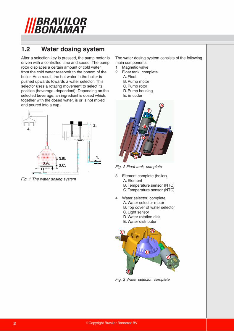
1.2 Water dosing systemAfter a selection key is pressed, the pump motor isdriven with a controlled time and speed. The pumprotor displaces a certain amount of cold waterfrom the cold water reservoir to the bottom of theboiler. As a result, the hot water in the boiler ispushed upwards towards a water selector. Thisselector uses a rotating movement to select itsposition (beverage−dependent). Depending on theselected beverage, an ingredient is dosed which,together with the dosed water, is or is not mixedand poured into a cup.
3.A.
1.
2. 4.
3.C.
3.B.
Fig. 1 The water dosing system
The water dosing system consists of the followingmain components:1. Magnetic valve2. Float tank, complete
A. FloatB. Pump motorC.Pump rotorD.Pump housingE. Encoder
ÁÁC
ÁÁ
ÁÁÁÁ
ÁÁ
A
B
ÁÁÁÁ
D
E
Fig. 2 Float tank, complete
3. Element complete (boiler)A. ElementB. Temperature sensor (NTC)C.Temperature sensor (NTC)
4. Water selector, completeA. Water selector motorB. Top cover of water selectorC.Light sensorD.Water rotation diskE. Water distributor
ÁÁA
ÁÁÁÁ
BÁÁC
ÁÁÁÁ
D
ÁÁÁÁ
E
Fig. 3 Water selector, complete

3�Copyright Bravilor Bonamat BV
1.2.1 Initialisation
The machine is switched on with the main switch.On the LCD (Liquid Crystal Display) the followingappear in succession: � all symbols that the display can show.
� the version number of the software(microprocessor) loaded from the factory.
� the version of the software table (Eeprom), alsoloaded from the factory.
This process takes approx. 3 seconds and endswith the steaming cup in the LCD display to showthat this phase has successfully finished.
1.2.2 Filling
The float tank and the boiler are connected by asiphon hose. Together, they form a communicatingvessel. When the machine is switched on for thefirst time, the float tank (fig.2 ) will be empty andthe float (fig.2 A.) will be low.� The magnetic valve (fig.1 ,1.) is opened and fills
water in the float tank with a speed of 2 litresper minute, depending on the pressure.
� The water in the float tank flows to the boilerthrough the hose under the float tank.
� After the water level has pushed the floatupwards, the water level in the float tank is thesame as that of the boiler. The magnetic valveis switched off.
Please note:Because the float tank is filled faster than thewater ”drops” to the boiler, the filling process willbe made with short intervals.
1.2.3 Heating
After the system is completely filled with water,element (fig.1 ,3.A.) is switched on by means of anelectronic relay (solid−state relay) in the machine.
The temperature sensor (fig.1 ,3.B.), which ismounted on the outside of the boiler, measuresthe actual temperature of the water. This ensuresthat the water in the boiler is heated to the desiredfinal temperature.
During the heating, a thermometer flashes in theLCD display. This indicates that the machine is notyet ready for use.
The temperature sensor is of the type NTC(Negative Temperature Coefficient). The higherthe measured temperature the lower theresistance of the sensor.
Hot water has a lower specific weight than coldwater. As a result, the hot water in the boiler willnot want to flow back to the float tank through thesiphon hose at the bottom. That part of the systemwill therefore remain cold. The latter is veryimportant because precisely the parts of the floattank are sensitive for scale.
The temperature sensor is mounted on the outsideof the boiler. As a result, there is no feed−throughin the wall and therefore there cannot be anylong−term leakage.
This measurement is less direct. This is why thetemperature is regulated proportionally. Theheating switches on for a certain time and off for acertain time.
After the period that the heating has been off, ameasurement is made. The next time, the heatingwill be on for longer or shorter.
The higher the temperature in the boiler, theshorter the moments become that the element ison, and the longer the intermediate time becomes.In this way, an accurate temperature is obtained inthe boiler.
There is a second temperature sensor on theboiler (fig.1 ,3.C.). This sensor monitors the outlettemperature of the dosed water. If this sensormeasures a too low temperature, the machine isblocked. No more water is dosed.
4 �Copyright Bravilor Bonamat BV
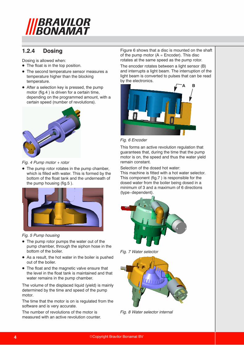
1.2.4 Dosing
Dosing is allowed when:� The float is in the top position.
� The second temperature sensor measures atemperature higher than the blockingtemperature.
� After a selection key is pressed, the pumpmotor (fig.4 ) is driven for a certain time,depending on the programmed amount, with acertain speed (number of revolutions).
Fig. 4 Pump motor + rotor
� The pump rotor rotates in the pump chamber,which is filled with water. This is formed by thebottom of the float tank and the underneath ofthe pump housing (fig.5 ).
Fig. 5 Pump housing
� The pump rotor pumps the water out of thepump chamber, through the siphon hose in thebottom of the boiler.
� As a result, the hot water in the boiler is pushedout of the boiler.
� The float and the magnetic valve ensure thatthe level in the float tank is maintained and thatwater remains in the pump chamber.
The volume of the displaced liquid (yield) is mainlydetermined by the time and speed of the pumpmotor.
The time that the motor is on is regulated from thesoftware and is very accurate.
The number of revolutions of the motor ismeasured with an active revolution counter.
Figure 6 shows that a disc is mounted on the shaftof the pump motor (A = Encoder). This discrotates at the same speed as the pump rotor.
The encoder rotates between a light sensor (B)and interrupts a light beam. The interruption of thelight beam is converted to pulses that can be readby the electronics.
A B
Fig. 6 Encoder
This forms an active revolution regulation thatguarantees that, during the time that the pumpmotor is on, the speed and thus the water yieldremain constant.
Selection of the dosed hot water: This machine is fitted with a hot water selector.This component (fig.7 ) is responsible for thedosed water from the boiler being dosed in aminimum of 3 and a maximum of 6 directions(type−dependent).
Fig. 7 Water selector
Fig. 8 Water selector internal
5�Copyright Bravilor Bonamat BV
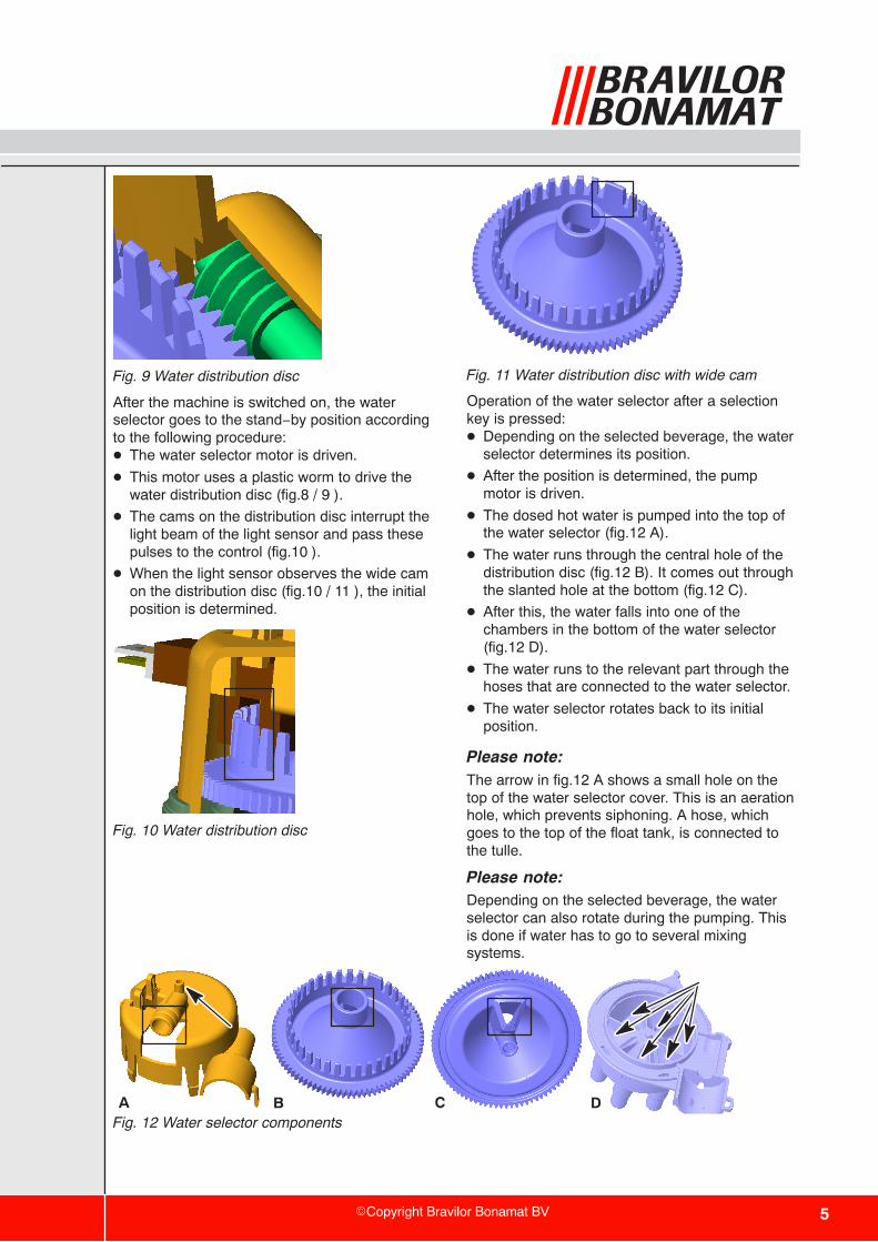
Fig. 9 Water distribution disc
After the machine is switched on, the waterselector goes to the stand−by position accordingto the following procedure:� The water selector motor is driven.
� This motor uses a plastic worm to drive thewater distribution disc (fig.8 / 9 ).
� The cams on the distribution disc interrupt thelight beam of the light sensor and pass thesepulses to the control (fig.10 ).
� When the light sensor observes the wide camon the distribution disc (fig.10 / 11 ), the initialposition is determined.
Fig. 10 Water distribution disc
Fig. 11 Water distribution disc with wide cam
Operation of the water selector after a selectionkey is pressed:� Depending on the selected beverage, the water
selector determines its position.
� After the position is determined, the pumpmotor is driven.
� The dosed hot water is pumped into the top ofthe water selector (fig.12 A).
� The water runs through the central hole of thedistribution disc (fig.12 B). It comes out throughthe slanted hole at the bottom (fig.12 C).
� After this, the water falls into one of thechambers in the bottom of the water selector(fig.12 D).
� The water runs to the relevant part through thehoses that are connected to the water selector.
� The water selector rotates back to its initialposition.
Please note:The arrow in fig.12 A shows a small hole on thetop of the water selector cover. This is an aerationhole, which prevents siphoning. A hose, whichgoes to the top of the float tank, is connected tothe tulle.
Please note:Depending on the selected beverage, the waterselector can also rotate during the pumping. Thisis done if water has to go to several mixingsystems.
A B C DFig. 12 Water selector components

6 �Copyright Bravilor Bonamat BV
1.3 Powder dosing systemThe powder dosing system consists of aningredient holder (canister) that is driven by amotor (canister motor).
After the start key is pressed, the canister motorwill rotate after a certain delay. This motor drives aworm, which transports the ingredient to thecanister outlet.
The control of the canister motor makes it possibleto regulate timing and dosing speedindependently. As a result, the ingredient can bepoured into the mixer at the same time that thewater flows out. However, the canister motor willstop slightly earlier than the water, to rinse themixing jug clean.
Depending on the type of ingredient, “beatersprings” are used in the canister. These springsensure that less tunnel formation occurs. This isthe caking of ingredient against the walls.
Fig. 13 Outlet canister

7�Copyright Bravilor Bonamat BV
1.4 Mixing systemThe mixing unit (fig.15 ) mixes the hot water andthe ingredient. After a selection key is pressed, thewater will be dosed in the mixing chamber after acertain delay. The product falls into the mixingchamber from above. Depending on the selectedbeverage, the mixer will start to rotate with acertain number of revolutions.
An exhaust opening is mounted on top of themixing chamber (fig.14 ). This cover has anopening at the rear, which is pressed into anexhaust opening through the sheet−metal work.The function of this exhaust system is to ensurethat vapour from the mixing chamber does not getthe chance to reach the ingredient holder outlet.Figure 16 shows an example of an exhaustsystem suited for three mixing systems.
Fig. 14 Exhaust hood
Fig. 15 Mixing unit
Fig. 16 Exhaust system for three mixing systems
1.5 Ventilation systemThe ventilation system (fig.17 ) removes thesteam, that developes during dosing. So thesettling of warm steam and condensation in themixing chamber will be prevented. Therefore themixing chamber will get less dirty.
Fig. 17 Ventilation system

8 �Copyright Bravilor Bonamat BV
1.6 Operating systemThe operating system consists of a:� Keyboard
� Main board
1.6.1 Keyboard
The keyboard is the printed circuit board with selection keys. Settings that can be changed inthe programming menu are also saved in theEeprom of this printed circuit board. When thekeyboard is replaced, the machine will thereforehave the factory settings.
1.6.2 Main board
The main board is located in the machine and isfitted with electronics to drive the machine. Thepower supply for the low−voltage currentcomponents is regulated from this board, as wellas the temperature regulation. On this board,there are one or more relays and semiconductorsthat can switch the electrical components on oroff.The main board is also fitted with amicroprocessor that regulates the boiler routine.

9�Copyright Bravilor Bonamat BV
1.7 Hardware protectionsThe machine is equipped with a number ofhardware protections. These protections ensurethat no dangerous situations can arise, such asoverheating and/or water in the machine.
1.7.1 Overflow protection
This protection is in the float tank and ensuresthat, if the water becomes too high, excess wateris passed through the overflow and hose to thebottom of the machine.
1.7.2 Back−flow protection
The water from the magnetic valve is sprayedagainst the cover of the float tank, via a pipe in thefloat tank. Then, it goes into the float tank itself. Inthis way, water is prevented from flowing back intothe system and getting into the water system if thewater pressure is released from the magneticvalve.
1.7.3 Boiling protection
The boiling protection consists of a relay on themain board (printed circuit relay) and atemperature sensor against the boiler. Thisprotection ensures that the machine can not boil.The separate electronic relay (solid−state relay) inthe machine is connected in series to amechanical printed circuit relay on the main board.This printed circuit relay is switched on when themachine is switched on and contains water, andswitched off when the machine is switched off.The solid−state relay is regularly switched on andoff to keep the water in the boiler at the righttemperature. The printed circuit relay does notswitch much. If the solid−state relay becomesdefective, this can make a direct connection. Thisis why the heating element is permanentlyswitched on. The temperature sensor constantlymeasures the temperature of the water. When thewater temperature is too high, the operatingsystem switches the printed circuit relay off. Thus,the heating element will also be switched off. Thisprevents the water from boiling.
1.7.4 High temperature safetyswitch
The high temperature safety switch is mounted onthe outside of the boiler by means of two Klixons.If, for whatever reason, the operating system doesnot switch the boiler off, the Klixons ensure thatthe voltage on the element is mechanicallyswitched off.
During the boiling dry process, evaporationescapes from the boiler. This vapour enters thewater selector and can possibly exit between thecover and distributor. To prevent a few drops fromentering the machine, a drip tray for the waterselector has been made (fig.18 ).
Fig. 18 Drip tray water selector

10 �Copyright Bravilor Bonamat BV
1.8 Software protectionDepending on the type of machine, it is providedwith a number of software protections. Thesoftware looks at all inputs and outputs of themachine during the entire process. If situationsarise that are not allowed, the software intervenes.This intervention usually results in the machinebeing switched off and an Error message in theLCD display. For possible solutions to these Errormessages, see the Error list underneath.
Fig. 19 LCD display with error message
ERROR LIST
Error 1 Not applicable
Error 2 Temperature in boiler too high:− If the temperature sensor (NTC)
measures a value that is outside its range(0 Ohm or infinity), the machine isswitched off and ’Error 2’ appears in theLCD display. This also applies if theboiling protection (see hardwareprotection) is activated.
Error 3 Magnetic valve open without selection:− When the start key is pressed, the
magnetic valve is activated. If this valve isactivated without the start key beingpressed, a timer is switched on. If themagnetic valve is activated again withinthis time without the start key beingpressed, this indicates a leakage in thewater system or that the water is boiling.The machine is switched off and ’Error 3’appears in the LCD display.
Error 4 Not applicable
Error 5 Water selector in wrong position:− The water selector returns to its initial
position during start−up and after eachdosing. If the selector cannot find itsposition during the execution of thisroutine, it switches off and ’Error 5’appears in the LCD display.
Error 6 Magnetic valve opened too long:− If, for whatever reason, the process of
filling the float tank takes too long, themachine is switched off and ’Error 6’appears in the LCD display.
Error 7 Wrong Chip card:− In a number of cases, it is possible to place
a chip card in a chip card reader. This ispresent on the keyboard. Any data presentcan be downloaded or uploaded. If thesoftware on this chip card does notcorrespond with the software in themachine, ’Error 7’ appears in the LCDdisplay.
Error 8 Communication error between both prints:− There is constant communication during
machine start−up and during use. This isdone via the flatcable between thekeyboard and the main board. Ifcommunication is impossible, ’Error 8’appears in the LCD display.
Error 9 Pump motor rotates too slow or does notrotate at all:
− The pump motor is rotating during machinestart−up and during use. The light sensordetects no or too little pulses and ’Error 9’will appear in the LCD display.
11�Copyright Bravilor Bonamat BV
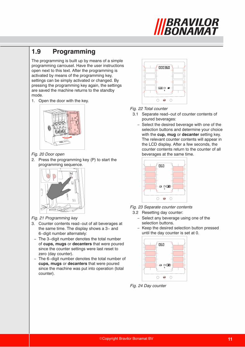
1.9 ProgrammingThe programming is built up by means of a simpleprogramming carrousel. Have the user instructionsopen next to this text. After the programming isactivated by means of the programming key,settings can be simply activated or changed. Bypressing the programming key again, the settingsare saved the machine returns to the standbymode.1. Open the door with the key.
Fig. 20 Door open2. Press the programming key (P) to start the
programming sequence.
Fig. 21 Programming key3. Counter contents read−out of all beverages at
the same time. The display shows a 3− and6−digit number alternately:
− The 3−digit number denotes the total numberof cups, mugs or decanters that were pouredsince the counter settings were last reset tozero (day counter).
− The 6−digit number denotes the total number ofcups, mugs or decanters that were pouredsince the machine was put into operation (totalcounter).
Fig. 22 Total counter3.1 Separate read−out of counter contents of
poured beverages:− Select the desired beverage with one of the
selection buttons and determine your choicewith the cup, mug or decanter setting key.The relevant counter contents will appear inthe LCD display. After a few seconds, thecounter contents return to the counter of allbeverages at the same time.
Fig. 23 Separate counter contents3.2 Resetting day counter:− Select any beverage using one of the
selection buttons.− Keep the desired selection button pressed
until the day counter is set at 0.
Fig. 24 Day counter
12 �Copyright Bravilor Bonamat BV
Fig. 25 Day counter to zero− Press the Enter key to go to the general
selection screen (fig.26 ).4. General selection screen:− General programming: press the Enter key
and continue with point 5.− Beverage−dependent settings: press the
selection key and continue with point 21.
Fig. 26 General selection screen5. Descaling program:− This machine is fitted with a descaling
program. After the START key is pressed inthis state of the LCD display, the de−scalingprogram is started. (For this purpose, read therelevant section of the user instructions.)
− Press CANCEL within 5 seconds if you decidenot to start the de−scaling program.
6. Boiler temperature:− Set the maximum temperature of the water in
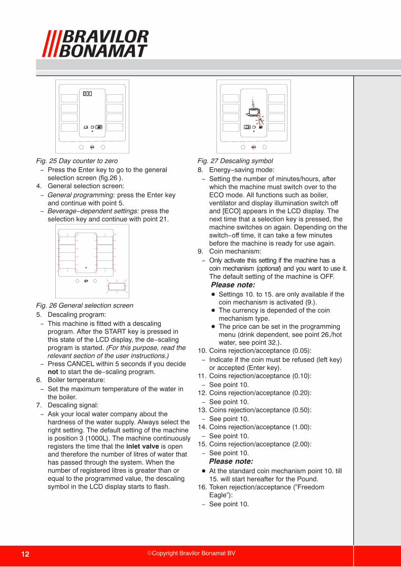
the boiler.7. Descaling signal:− Ask your local water company about the
hardness of the water supply. Always select theright setting. The default setting of the machineis position 3 (1000L). The machine continuouslyregisters the time that the inlet valve is openand therefore the number of litres of water thathas passed through the system. When thenumber of registered litres is greater than orequal to the programmed value, the descalingsymbol in the LCD display starts to flash.
Fig. 27 Descaling symbol8. Energy−saving mode:− Setting the number of minutes/hours, after
which the machine must switch over to theECO mode. All functions such as boiler,ventilator and display illumination switch offand [ECO] appears in the LCD display. Thenext time that a selection key is pressed, themachine switches on again. Depending on theswitch−off time, it can take a few minutesbefore the machine is ready for use again.
9. Coin mechanism:− Only activate this setting if the machine has a
coin mechanism (optional) and you want to use it.The default setting of the machine is OFF.Please note:� Settings 10. to 15. are only available if the
coin mechanism is activated (9.).� The currency is depended of the coin
mechanism type.� The price can be set in the programming
menu (drink dependent, see point 26./hotwater, see point 32.).
10. Coins rejection/acceptance (0.05):− Indicate if the coin must be refused (left key)
or accepted (Enter key).11. Coins rejection/acceptance (0.10):− See point 10.
12. Coins rejection/acceptance (0.20):− See point 10.
13. Coins rejection/acceptance (0.50):− See point 10.
14. Coins rejection/acceptance (1.00):− See point 10.
15. Coins rejection/acceptance (2.00):− See point 10.
Please note:� At the standard coin mechanism point 10. till
15. will start hereafter for the Pound.16. Token rejection/acceptance (”Freedom
Eagle”):− See point 10.
13�Copyright Bravilor Bonamat BV
17. Token rejection/acceptance (freeprogrammable):
− See“Azkoyen validator §1.4.7.1 en §1.4.7.2”.18. Copy Card:− Customer specific settings can be copied on
the chipcard, whereupon these can bedownloaded to other equivalent machines.� The procedure can be found on the
extranet “Special Codes”.19. General selection screen (all keys that are
now lit can be selected).20. Amount per cup.− Setting the amount of water in ml. The
software will convert a larger amount to alonger pumping time. If the amount of water ischanged, the basic strength is automaticallyadapted, so that the strength increases ordecreases proportionally.
21. Programming (drink dependent).22. Amount per cup (drink dependent):− Setting the amount of water in ml. The
software will convert a larger amount to alonger pumping time. If the amount of water ischanged, the basic strength is automaticallyadapted, so that the strength increases ordecreases proportionally.
23. Amount per mug (drink dependent):− See ”amount for mug (drink dependent)”.23.1 Blocking mugs:− Decrease the value set for mug to the
minimum. The display will show ’OFF’.− If the machine has been set to paid delivery,
it is not possible to pour a mug.24. Amount per decanter (drink dependent):− See ”amount for cup (drink dependent)”.− With a number of beverages, the decanter
function is blocked in the factory.24.1 Blocking decanters:− Decrease the value set per decanter to the
minimum. The display will show ’OFF’.− If the machine has been set to paid delivery,
it is not possible to pour a decanter.
25. Basic strength (drink dependent):− Setting amount of ingredient (in %). The
software translates the programmedpercentage to the speed of the canister motorand therefore the strength of the ingredient.(See ingredient sheet).
26. Price−fixing (drink dependent) (optional):− Set the desired price.
27. General selection screen.28. Programming (hot water):29. Amount per cup (hot water):− Here, the amount of water can be set in ml.
The software will convert a larger amount to alonger pumping time.
30. Amount for mug (hot water):− See ”amount for cup (hot water)”.30.1 Manually blocking mugs:− Decrease the value set for mug to the
minimum. The display will show ’OFF’.− If the machine has been set to paid delivery,
it is not possible to pour a mug.31. Amount per decanter (hot water):− See ”amount for cup (hot water)”.31.1 Manually blocking decanters:− Decrease the value set per decanter to the
minimum. The display will show ’OFF’.− If the machine has been set to paid delivery,
it is not possible to pour a decanter.32. Price−fixing (hot water) (optional):− Set the desired price.
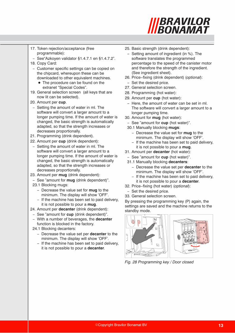
33. General selection screen.By pressing the programming key (P) again, thesettings are saved and the machine returns to thestandby mode.
Fig. 28 Programming key / Door closed

© 06−2008


