COMPRESSOR MODEL P600/XP535WCU-T4i (E90) HP450/VHP400WCU-T4i (E91) Doosan Infracore Portable Power 1293 Glenway Drive Statesville, N.C. 28625 DoosanPortablePower.com P/N: 46614501 (07-2012) Rev A This manual contains important safety information. Do not destroy this manual. This manual must be available to the personnel who operate and maintain this compressor. OPERATION and MAINTENANCE MANUAL
Transcript
COMPRESSOR MODEL
P600/XP535WCU-T4i (E90)
HP450/VHP400WCU-T4i (E91)
Doosan Infracore Portable Power 1293 Glenway DriveStatesville, N.C. 28625DoosanPortablePower.com
P/N: 46614501 (07-2012) Rev A
This manual contains important safety information.Do not destroy this manual.This manual must be available to the personnel who operate and maintain this compressor.
InformationThe contents of this manual are considered to be proprietary and confidential to Doosan Infracore Portable Power (herein referred to as “Portable Power”), and should not be reproduced without the prior written permission of Portable Power.
Nothing contained in this document is intended to extend any promise, warranty or representation, expressed or implied, regarding the Portable Power products described herein. Any such warranties or other terms and conditions of sale of products shall be in accordance with the standard terms and conditions of sale for such products, which are available upon request.
This manual contains instructions and technical data to cover all routine operation and scheduled maintenance tasks by operation and maintenance staff. Major overhauls are outside the scope of this manual and should be referred to an authorized Portable Power Service department.
All components, accessories, pipes, and connectors added to the compressed air system should be:
• of good quality, procured from a reputable manufacturer and, wherever possible, beof a type approved by Portable Power.
• clearly rated for a pressure at least equal to the compressor safety valve setting.
• compatible with the compressor oil.
• accompanied with instructions for safe installation, operation, and maintenance.
Details of approved equipment are available from the Portable Power Service departments. The use of repair parts other than those included within the approved parts list may create hazardous conditions over which Portable Power has no control. Therefore, Portable Power cannot be held responsible for equipment in which non-approved repair parts are installed.
Portable Power reserves the right to make changes and improvements to products without notice and without incurring any obligation to make such changes or add such improvements to products sold previously.
The intended uses of this compressor are outlined below and examples of unapproved usage are also given. However, Portable Power cannot anticipate every application or work situation that may arise. If in doubt, consult supervision.
This compressor has been designed and supplied for above ground operation to be used for compression of normal ambient air containing no additional gases, vapors, or particles within the ambient temperature range specified in the General Data Section of this manual.
Foreword Operation & Maintenance Manual
9
This compressor should NOT be used:
A. For direct or indirect human consumption of the compressed air.
B. Outside the ambient temperature range specified in the General Data Sectionof this manual.
C. When an actual or foreseeable risk of hazardous levels of flammable gases orvapors exists.
D. With other than Portable Power approved components.
E. With guards, controls, or switches missing or disabled.
F. For storage or transportation of materials inside or on the enclosure.
Portable Power accepts no responsibility for errors in translation of this manual from the original English version.
You, as the customer, are expected to provide certain service and maintenance items. Your Portable Power dealer will provide all other more detailed service and maintenance items on a special preventive maintenance schedule for each compressor. It is very important that the minimum service and maintenance requirements explained in this manual be performed at the required intervals. Exceeding these intervals may reduce the reliability of the compressor.
The purpose of this manual is to train the operator with functions, operation, and basic service and maintenance requirements of the compressor. During the preparation of this manual, every effort was made to ensure the accuracy and adequacy of the contents.
Your Portable Power dealer will assist with setup and initial startup of the compressor and will also provide brief operating and service instructions. Before starting the compressor, this manual and instructions should be carefully read to obtain a thorough knowledge of the duties to be performed. Please take pride in the compressor, keep it clean and in good mechanical condition.
To enable proper maintenance records, Portable Power provides a Noise Emission Control Maintenance Log in the Noise Emission Section of this manual. The Noise Emission Section contains a recommended Maintenance schedule and provides space in the log for the technician to note what service and maintenance was done, by whom, where, and when.
Operation & Maintenance Manual Foreword
10
11
Safety
Operation & Maintenance Manual Safety
12
Safety PrecautionsNever operate the compressor without first observing all safety warnings and carefully reading the Operation and Maintenance Manual shipped from the factory with this compressor.
Ensure the operator reads and understands the decals and consults the manuals before operation or performing maintenance.
Ensure all maintenance personnel are adequately trained, competent, and have read the manuals.
Ensure all protective covers are in place and the canopy/doors are closed during operation.
The specification of this compressor is such that the compressor is not suitable for use in flammable gas risk areas. If such an application is required, all local regulations, codes of practice, and site rules must be observed. To ensure the compressor can operate in a safe and reliable manner, additional equipment such as gas detection, exhaust spark arrestors, and intake (shut-off) valves may be required, dependent on local regulations or the degree of risk involved.
A weekly visual check must be made of all fasteners/fixing screws securing mechanical parts. In particular, safety-related parts such as coupling hitch, drawbar components, wheels, tires, and lifting bail should be checked for total security.
All components which are loose, damaged, or unserviceable must be rectified without delay.
Air discharged from this compressor may contain carbon monoxide or other contaminants which will cause serious injury or death. Do not breathe discharged air.
This compressor produces loud noise with the doors open or service valve vented. Extended exposure to loud noise can cause hearing loss. Always wear hearing protection when doors are open or service valve is vented.
Never inspect or service the compressor without first disconnecting battery cable(s) to prevent accidental starting.
Do not use petroleum products (solvents or fuels) under high pressure as this can penetrate the skin and result in serious illness. Wear eye protection while cleaning the compressor with compressed air to prevent debris from injuring eye(s).
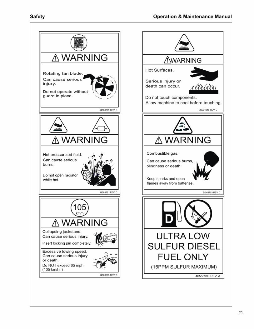
Rotating fan blade can cause serious injury. Do not operate without fan guard in place.
Use care to avoid contacting hot surfaces (engine exhaust manifold and piping, air receiver, and air discharge piping, etc.).
Ether is an extremely volatile, highly flammable gas. When it is specified as a starting aid, use sparingly. Do not use Ether if the engine has glow plugs or inlet heater starting aids. Engine damage will result.
Never operate the compressor with guards, covers, or screens removed. Keep hands, hair, clothing, tools, blow gun tips, etc. well away from moving parts.
Safety Operation & Maintenance Manual
13
Compressed AirCompressed air can be dangerous if incorrectly handled. Prior to performing maintenance or service on the compressor, ensure all pressure is vented from the system and the compressor cannot be started accidentally.
Ensure the compressor is operating at the rated pressure and the rated pressure is known to all relevant personnel.
All air pressure equipment installed in, or connected to, the compressor must have safe working pressure ratings of at least the compressor safety valve setting.
If more than one compressor is connected to one common downstream plant, effective check valves and isolation valves must be fitted and controlled by work procedures, to ensure one compressor cannot accidentally be pressurized or over pressurized by another.
Compressed air must NOT be used for a direct feed to any form of breathing apparatus or mask.
Compressed air can cause serious injury or death. Relieve pressure before removing filler plugs/caps, fittings, or covers.
Air pressure can remain trapped in air supply line which can result in serious injury or death. Always carefully vent air supply line at tool or vent valve before performing any service or maintenance.
Discharged air contains a very small percentage of compressor lubricating oil and care should be taken to ensure downstream equipment is compatible.
If discharged air is to be ultimately released into a confined space, adequate ventilation must be provided.
When using compressed air, always use appropriate personal protective equipment.
All pressure containing parts, especially flexible hoses and their couplings, must be regularly inspected, be free from defects, and be replaced according to the manual instructions.
Avoid bodily contact with compressed air.
The safety valve located in the separator tank must be checked periodically for correct operation.
Whenever the compressor is stopped, air will flow back into the compressor from downstream devices or systems unless the service valve is closed. Install a check valve at the compressor service valve to prevent reverse flow in the event of an unexpected shutdown when the service valve is open.
Disconnected air hoses whip and can cause serious injury or death. Always attach a safety flow restrictor to each hose at the source of supply or branch line in accordance with OSHA Regulation 29CFR Section 1926.302(b).
Never allow the compressor to sit stopped with pressure in the separator tank or piping.
Operation & Maintenance Manual Safety
14
Exhaust SystemHot engine exhaust gas and hot exhaust system surfaces are produced during and after compressor operation. Avoid contact with exhaust gas and hot exhaust system surfaces. Keep flammable and combustible materials away. Do not operate compressor on, under, or near flammable or combustible materials.
The potential for higher temperatures is present when the exhaust aftertreatment system undergoes regeneration. Refer to Engine Manual for further safety instructions and information on the exhaust aftertreatment system and controls.
MaterialsThe following substances may be produced during the operation of this compressor:
• brake lining dust
• engine exhaust fumes
WARNING!
Avoid inhalation of material substances.
Ensure that adequate ventilation of the cooling system and exhaust gases is maintained at all times.
The following substances are used in the manufacture of this compressor and may be hazardous to health if used incorrectly:
• antifreeze
• compressor oil
• engine oil
• preservative grease, lubricating grease
• rust preventative
• diesel fuel
• battery electrolyte
WARNING!
Avoid ingestion, skin contact, and inhalation of fumes.
Should compressor oil come into contact with the eyes, irrigate with water for at least 5 minutes.
Safety Operation & Maintenance Manual
15
Should compressor oil come into contact with the skin, wash off immediately. Consult a physician if large amounts of compressor oil are ingested or if compressor oil is inhaled. Never give fluids or induce vomiting if the patient is unconscious or having convulsions.
Safety data sheets for compressor and engine oils should be obtained from the oil supplier.
Do NOT start or operate this compressor in a confined area. Avoid breathing exhaust fumes when working on or near the compressor.
This compressor may include such materials as oil, diesel fuel, antifreeze, brake fluid, oil/air filters, and batteries which may require proper disposal when performing maintenance or service tasks. Contact local authorities for proper disposal of these materials.
BatteryA battery contains sulfuric acid and can produce gases which are corrosive and potentially explosive. Avoid contact with skin, eyes, and clothing. In case of contact, flush area immediately with water.
WARNING!
Do not attempt to jump-start a frozen battery since this may cause it toexplode.
Exercise extreme caution when using an external method to jump-start a unit. Verify the electrical systems on the weak battery system and the external jump system are the same voltage type system, 12VDC or 24VDC. Connect the Positive (+) terminal of the external system to the Positive (+) terminal on the weak system. Connect the Negative (-) terminal of the external system to the Negative (-) terminal of the weak system. Always disconnect the two systems in reverse order.
RadiatorHot engine coolant and steam can cause injury. Ensure the Radiator Pressure Cap is removed with due care and attention.
Do not remove the pressure cap from a HOT radiator. Allow radiator to cool before removing pressure cap.
Operation & Maintenance Manual Safety
16
WARNING!
Hot engine coolant and steam can cause injury. When adding coolant orantifreeze solution to the engine radiator, stop the engine and allowradiator to cool prior to releasing the radiator pressure cap. Using a clothto protect the hand, slowly release the radiator pressure cap, absorbingany released fluid with the cloth. Do not remove the radiator pressure capuntil all excess fluid is released and the engine cooling system fullydepressurized.
WARNING!
Follow the instructions provided by the antifreeze supplier when addingor draining the antifreeze solution. It is advisable to wear personalprotective equipment to prevent skin and eye contact with the antifreezesolution.
TransportWhen loading or transporting the compressor, ensure that the specified lifting and tie down points are used.
When loading or transporting the compressor, ensure that the towing vehicle, its size, weight, towing hitch, and electrical supply are all suitable to provide safe and stable towing at speeds either, up to the legal maximum for the country in which it is being towed or as specified for the compressor model if lower than the legal maximum. Do not exceed gross vehicle weight rating.
Before towing the compressor, ensure:
• the tires and towing hitch are in a serviceable condition and tires are properly inflated.
• the canopy is secure.
• all ancillary equipment is stored in a safe and secure manner.
• the brakes and lights are functioning correctly and meet necessary road trafficrequirements.
• breakaway cables/safety chains are connected to the towing vehicle.
The compressor must be towed in a level attitude in order to maintain correct handling, braking, and lighting functions. This can be achieved by correct selection and adjustment of the vehicle towing hitch and, on variable height running gear, adjustment of the drawbar.
1. Ensure wheels, tires, and drawbar connectors are in safe operating conditionand drawbar is properly connected before towing.
2. When parking, always use the handbrake and, if necessary, suitable wheelchocks.
Safety Operation & Maintenance Manual
17
Safety chains/breakaway cable and their adjustment (where fitted).
Ensure breakaway cable is securely coupled to the towed compressor and also to a substantial anchorage point on the towing vehicle.
Ensure cable length is as short as possible, while still allowing enough slackness for the towed compressor to articulate without the brake being applied.
Attach safety chains to the towing vehicle at substantial anchorage points of suitable strength.
Ensure effective chain length is as short as possible while still allowing normal articulation of the towed compressor and proper operation of the breakaway cable.
Operation & Maintenance Manual Safety
18
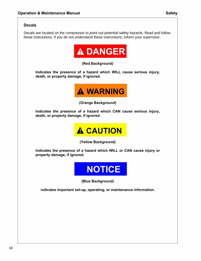
Decals
Decals are located on the compressor to point out potential safety hazards. Read and follow these instructions. If you do not understand these instructions, inform your supervisor.
DANGER!
(Red Background)
Indicates the presence of a hazard which WILL cause serious injury,death, or property damage, if ignored.
WARNING!
(Orange Background)
Indicates the presence of a hazard which CAN cause serious injury,death, or property damage, if ignored.
CAUTION!
(Yellow Background)
Indicates the presence of a hazard which WILL or CAN cause injury orproperty damage, if ignored.
NOTICE(Blue Background)
Indicates important set-up, operating, or maintenance information.
Safety Operation & Maintenance Manual
19
Free Safety Decals
To promote communication of Safety Warnings on products manufactured by the Portable Power Division in Statesville, N.C., Safety Decals are available FREE of charge. Safety Decals are identified by the decal heading: DANGER, WARNING, CAUTION, NOTICE.
Decal part numbers are located in the lower right hand corner of each decal and are also listed in the compressor Parts Manual. Submit orders for Safety Decals to the Statesville Parts Service Dept. The no charge order should contain only Safety Decals.
Help promote product safety! Ensure decals are present on the compressor. Replace decals that are not readable.
Operation & Maintenance Manual Safety
20
54629902 REV. C
attach safety device(OSHA Valve) at source of
When using air tools
air supply for each tool.
Close service valve andoperate tool to venttrapped air beforeperforming any service.
Do not breathe this air.
54568795 REV. C 4655988
54749163 REV. C
5 S 3M
Hot
Safety Operation & Maintenance Manual
21
Operation & Maintenance Manual Safety
22
Safety Operation & Maintenance Manual
23
Operation & Maintenance Manual Safety
24
Decals
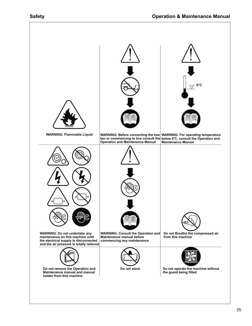
Graphic Form and Meaning of ISO Symbols
Prohibition / Mandatory Information / Instructions Warning
WARNING: Electrical Shock Risk WARNING: Pressurized Component or System
WARNING: Hot Surface
WARNING: Pressure Control WARNING: Corrosion Risk WARNING: Air/Gas Flow or Air Discharge
WARNING: Pressurized Vessel WARNING: Hot and harmful exhaust gas
WARNING: Maintain correct tire pressure (Refer to the GENERAL
INFORMATION section of this manua
Safety Operation & Maintenance Manual
25
0 Co
WARNING: Flammable Liquid WARNING: Before connecting the towbar or commencing to tow consult theOperation and Maintenance Manual
WARNING: For operating temperaturebelow 0 C, consult the Operation andMaintenance Manual
o
WARNING: Do not undertake anymaintenance on this machine untilthe electrical supply is disconnectedand the air pressure is totally relieved
WARNING: Consult the Operation andMaintenance manual beforecommencing any maintenance
Do not Breathe the compressed airfrom this machine
Do not remove the Operation andMaintenance manual and manualholder from this machine
Do not stack Do not operate the machine withoutthe guard being fitted
Operation & Maintenance Manual Safety
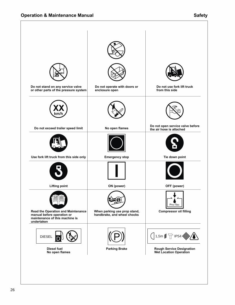
26
XXkm/h
DIESEL IP541,5m
Do not operate with doors orenclosure open
Do not stand on any service valveor other parts of the pressure system
Do not use fork lift truckfrom this side
Diesel fuelNo open flames
Parking Brake Rough Service DesignationWet Location Operation
Read the Operation and Maintenancemanual before operation ormaintenance of this machine isundertaken
When parking use prop stand,handbrake, and wheel chocks
Compressor oil filling
Lifting point ON (power) OFF (power)
Use fork lift truck from this side only Emergency stop Tie down point
Do not exceed trailer speed limit No open flamesDo not open service valve beforethe air hose is attached
Safety Operation & Maintenance Manual
27
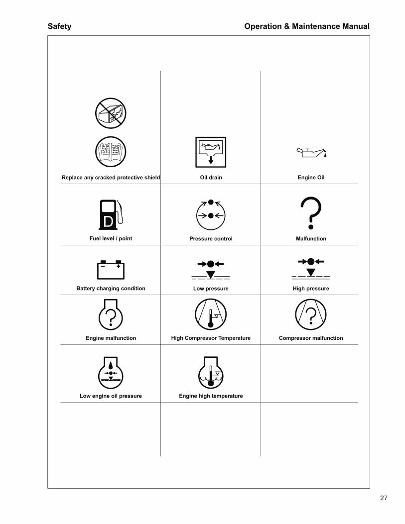
Replace any cracked protective shield Oil drain Engine Oil
Fuel level / point Pressure control Malfunction
Battery charging condition Low pressure High pressure
Engine malfunction High Compressor Temperature Compressor malfunction
Low engine oil pressure Engine high temperature
Operation & Maintenance Manual Safety
28
29
Noise Emission
Operation & Maintenance Manual Noise Emission
30
Noise EmissionThis section pertains only to compressors distributed within the United States.
WARNING!
TAMPERING WITH NOISE CONTROL SYSTEM PROHIBITED
Federal law prohibits the following acts or the causing thereof:
(1) The removal or rendering inoperative by any persons, other than for purposes of maintenance, repair, or replacement, of any device or element of design incorporated into any new compressor for the purpose of noise control prior to its sale or delivery to the ultimate purchaser or while it is in use; or (2) the use of the compressor after such device or element of design has been removed or rendered inoperative by any person.
Among those acts included in the prohibition against tampering are these:
1. Removal or rendering inoperative any of the following:
a. the engine exhaust system or parts thereofb. the air intake system or parts thereofc. enclosure or parts thereof
2. Removal of any of the following:
a. fan shroudb. vibration mountsc. sound absorption material
3. Operation of the compressor with any of the enclosure doors open.
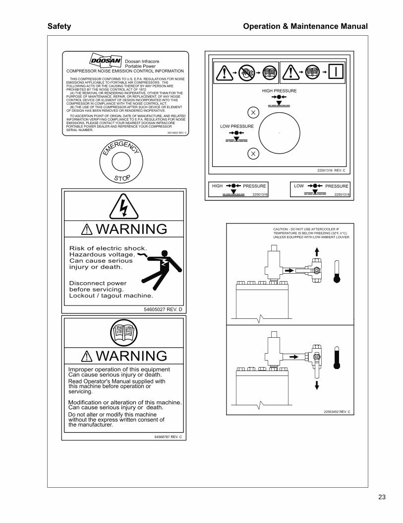
Compressor Noise Emission Control Information
A. The removal or rendering inoperative, other than for the purpose ofmaintenance, repair, or replacement of any noise control device or element ofdesign incorporated into this compressor in compliance with the noise controlact;
B. The use of this compressor after such device or element of design has beenremoved or rendered inoperative.
NOTE: the above information applies only to compressors that are builtin compliance with the U.S. Environmental Protection Agency.
Portable Power reserves the right to make changes or add improvements without notice and without incurring any obligation to make such changes or add such improvements to products sold previously.
The Purchaser is urged to include the above provisions in any agreement for any resale of this compressor.
Noise Emission Operation & Maintenance Manual
31
Maintenance Log
The Noise Control Act of 1972 (86 Stat. 1234) prohibits tampering with the noise control system of any compressor manufactured and sold under the above regulations, specifically the following acts or the causing thereof:
(1) the removal or rendering inoperative by any persons, other than for purposes of maintenance, repair, or replacement, of any device or element of design incorporated into new compressor for the purpose of noise control prior to its sale or delivery to the ultimate purchaser or while it is in use; or (2) the use of the compressor after such device or element of design has been removed or rendered inoperative by any person.
Noise Emission WarrantyThe manufacturer warrants to the ultimate purchaser and each subsequent purchaser that this air compressor was designed, built and equipped to conform at the time of sale to the first retail purchaser, with all applicable U.S. EPA Noise Control Regulations.
This warranty is not limited to any particular part, component, or system of the air compressor. Defects in the design, assembly or in any part, component, or system of the compressor which, at the time of sale to the first retail purchaser, caused noise emissions to exceed Federal Standards are covered by this warranty for the life of air compressor.(40CFR204.58-1)
COMPRESSOR MODEL_________________________
SERIAL NO. __________________________________
USER UNIT NO. _______________________________
UNIT IDENTIFICATION
Engine Make & Model:_________________
DEALER OR DISTRIBUTOR FROMWHOM PURCHASED:
Serial No.:__________________________ __________________________________
Purchaser or Owner:__________________ __________________________________
Address: ___________________________ Date Purchased:_____________________
Operation & Maintenance Manual Noise Emission
32
IntroductionThe compressor for which this Maintenance Log is provided conforms to U.S. E.P.A. Regulations for Noise Emissions, applicable to Portable Air Compressors.
The purpose of this book is to provide (1) the Maintenance Performance Schedule for all required noise emission controls and (2) space so that the purchaser or owner can record what maintenance was done, by whom, where and when. The Maintenance Schedule and detailed instructions on the maintenance items are given on following page.
Maintenance Schedule
A. Compressed Air Leaks
Correct all compressed air leaks during the first shutdown period after discovery. If severe enough to cause serious noise problems and efficiency loss, shut down immediately and correct the leak(s).
B. Safety and Control Systems
Repair or replace all safety and control systems or circuits as malfunction occurs. No compressor should be operated with either system bypassed, disabled, or nonfunctional.
C. Acoustic Materials
In daily inspections, observe these materials. Maintain all acoustic material as nearly as possible in its original condition. Repair or replace all sections that have: 1) sustained damage, 2) have partially separated from panels to which they were attached, 3) are missing, or have otherwise deteriorated due to severe operating or storage conditions.
ITEM AREA PERIOD
A. Compressed Air Leaks As Detected
B. Safety and Control Systems As Detected
C. Acoustic Materials Daily
D. Fasteners 100 hours
E. Enclosure Panels 100 hours
F. Air Intake & Engine Exhaust 100 hours
G. Cooling Systems 250 hours
H. Isolation Mounts 250 hours
I. Engine Operation See Operator’s Manual
J. Fuels & Lubricants See Operator’s Manual
Noise Emission Operation & Maintenance Manual
33
D. Fasteners
All fasteners such as hinges, nuts, bolts, clamps, screws, rivets, and latches should be inspected for looseness after each 100 hours of operation. They should be retightened, repaired, or if missing, replaced immediately to prevent subsequent damage and noise emission increase.
E. Enclosure Panels
Enclosure panels should be inspected at 100 hour operational intervals. All panels that are warped, punctured, torn, or otherwise deformed, such that their noise containment function is reduced, should be repaired or replaced before the next operation interval. Doors, access panels, and hatch closures especially, should be checked and adjusted at this time to ensure continuous seating between gasket or acoustic material and the mating frame.
F. Air Intake and Engine Exhaust
Engine and compressor air intake and engine exhaust systems should be inspected after each 100 hours of operation for loose, damaged, or deteriorated components. Repairs or replacements should be made before the next period of use.
G. Cooling Systems
All components of the cooling system for engine water and compressor oil should be inspected every 250 hours of use. Any discrepancies found should be corrected before placing the compressor back in operation. Unrestricted airflow over the radiator and oil cooler must be maintained at all times during operation.
H. Isolation Mounts
Engine/airend isolation mounts should be inspected after each 250 hours of operation. Those mounts with cracks or splits in the molded rubber or with bent or broken bolts due to operation or storage in severe environments should be replaced with equivalent parts.
I. Engine Operation
Inspect and maintain engine condition and operation as recommended in the manuals supplied by the engine manufacturer.
J. Fuels and Lubricants
Use only the types and grades of fuels and lubricants recommended in the Operator and Maintenance Manual and Engine Manual.
Operation & Maintenance Manual Noise Emission
34
MAINTENANCE RECORD FOR NOISE EMISSION CONTROL AND EXTENDED WARRANTY
SERVICE AIR: Allows operator to load compressor after warm-up.
HI PRESSURE: Allows operator to switch to high pressure mode.
LO PRESSURE: Allows operator to switch to low pressure mode.
UP: Pressing and releasing the UP Button scrolls up through parameter lists and menu choices or increases a value one item/unit at a time. Pressing and holding the UP Button continuously scrolls up through parameter lists, menu choices, or increases a value until the end of the parameter list, menu choices, or maximum parameter value is reached.
DOWN: The DOWN Button functions identical to the UP Button with the exception that its direction for all displays, menu choices, and values is down or decreasing.
ENTER: Pressing and releasing this button provides enter functionality when the display requires you to choose a menu item, parameter selection, or value input. Pressing and holding this switch for approximately three seconds while any of the Main Screens are displayed brings up the Main Menu. Pressing the ENTER Button after an alert or fault has been displayed acknowledges the message and the display unit returns to the Default Screen.
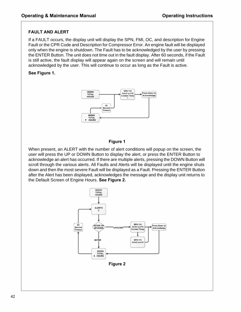
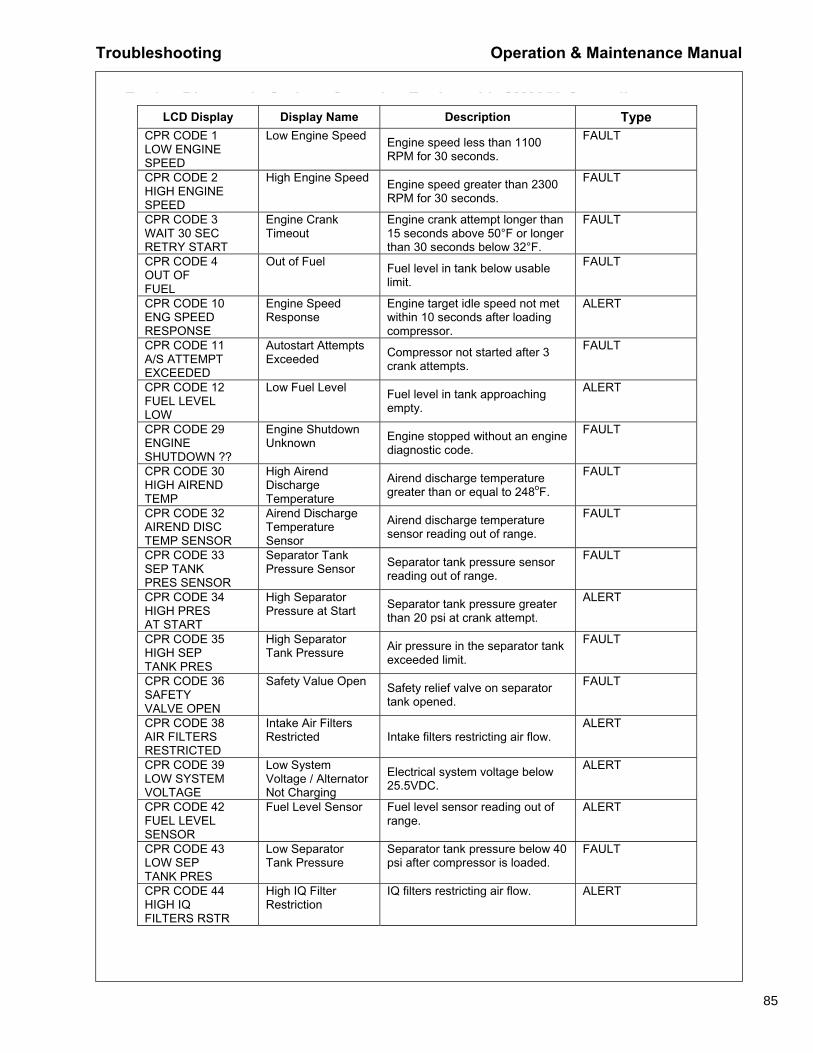
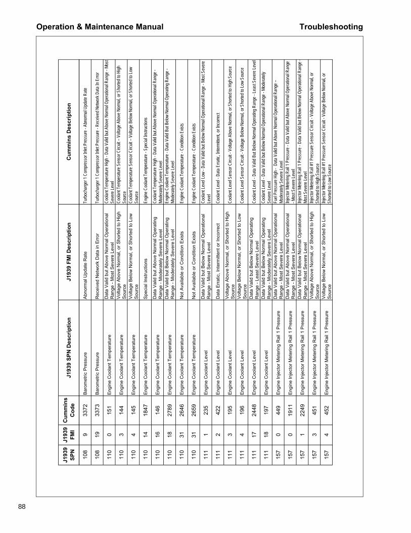
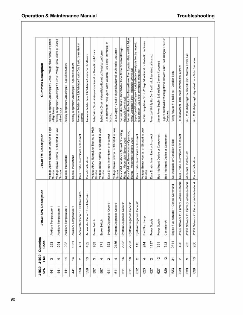
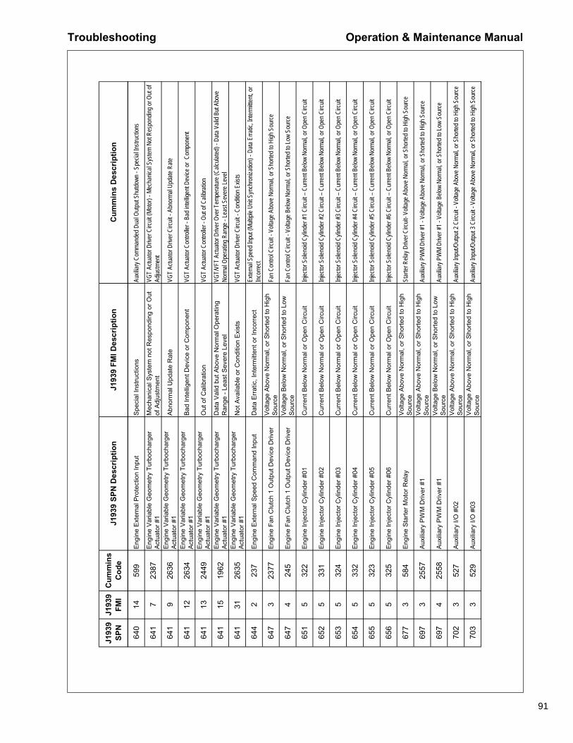
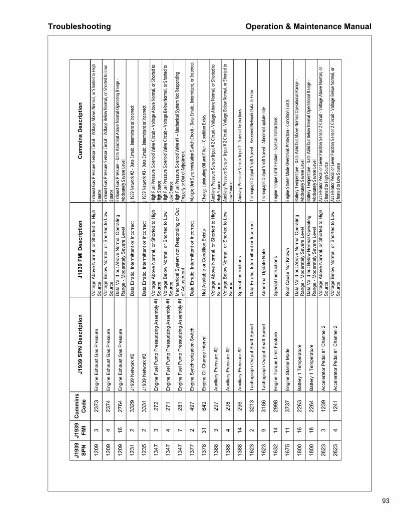
If a FAULT occurs, the display unit will display the SPN, FMI, OC, and description for Engine Fault or the CPR Code and Description for Compressor Error. An engine fault will be displayed only when the engine is shutdown. The Fault has to be acknowledged by the user by pressing the ENTER Button. The unit does not time out in the fault display. After 60 seconds, if the Fault is still active, the fault display will appear again on the screen and will remain until acknowledged by the user. This will continue to occur as long as the Fault is active.
See Figure 1.
Figure 1
When present, an ALERT with the number of alert conditions will popup on the screen, the user will press the UP or DOWN Button to display the alert, or press the ENTER Button to acknowledge an alert has occurred. If there are multiple alerts, pressing the DOWN Button will scroll through the various alerts. All Faults and Alerts will be displayed until the engine shuts down and then the most severe Fault will be displayed as a Fault. Pressing the ENTER Button after the Alert has been displayed, acknowledges the message and the display unit returns to the Default Screen of Engine Hours. See Figure 2.
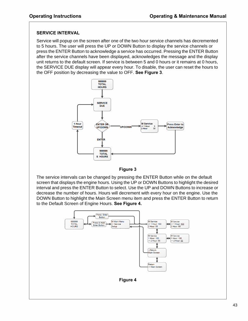
Service will popup on the screen after one of the two hour service channels has decremented to 5 hours. The user will press the UP or DOWN Button to display the service channels or press the ENTER Button to acknowledge a service has occurred. Pressing the ENTER Button after the service channels have been displayed, acknowledges the message and the display unit returns to the default screen. If service is between 5 and 0 hours or it remains at 0 hours, the SERVICE DUE display will appear every hour. To disable, the user can reset the hours to the OFF position by decreasing the value to OFF. See Figure 3.
Figure 3
The service intervals can be changed by pressing the ENTER Button while on the default screen that displays the engine hours. Using the UP or DOWN Buttons to highlight the desired interval and press the ENTER Button to select. Use the UP and DOWN Buttons to increase or decrease the number of hours. Hours will decrement with every hour on the engine. Use the DOWN Button to highlight the Main Screen menu item and press the ENTER Button to return to the Default Screen of Engine Hours. See Figure 4.
The MidPort is user configured to display in English, Spanish, or French languages and in either English or Metric units. The Language and Display units can be changed by accessing the Setup Menu. To access the Setup Menu, press and hold the ENTER Button while the Default Screen of Engine Hours is displayed until the Main Menu appears. Scroll to the Setup option using the DOWN Button then press the ENTER Button. Use the DOWN or UP Buttons to highlight the chosen unit and PRESS the ENTER Button to select. To return to the Default Screen of Engine Hours, use the DOWN Button to highlight the Main Screen menu item and press the ENTER Button. See Figure 5.
QUICKVIEW SCREENS (ENGINE AND COMPRESSOR PARAMETERS)
The Quick View Screens allow for easy viewing of up to 18 commonly used parameters by pressing the UP and DOWN Buttons. Pressing the UP and DOWN Buttons continuously loops through the Quick View Screens (i.e., when the last screen is reached pressing the DOWN Button displays the first screen and vice versa).
Figure 6
Note 1: Only the parameters that are available from the engine or compressor will be displayed.
Note 2: Unit times out after 3 minutes of inactivity and returns to the Default Screen of Engine Hours.
Note 3: Pressing the Enter Button while viewing a Quickview Screen will return to the Default Screen of Engine Hours.
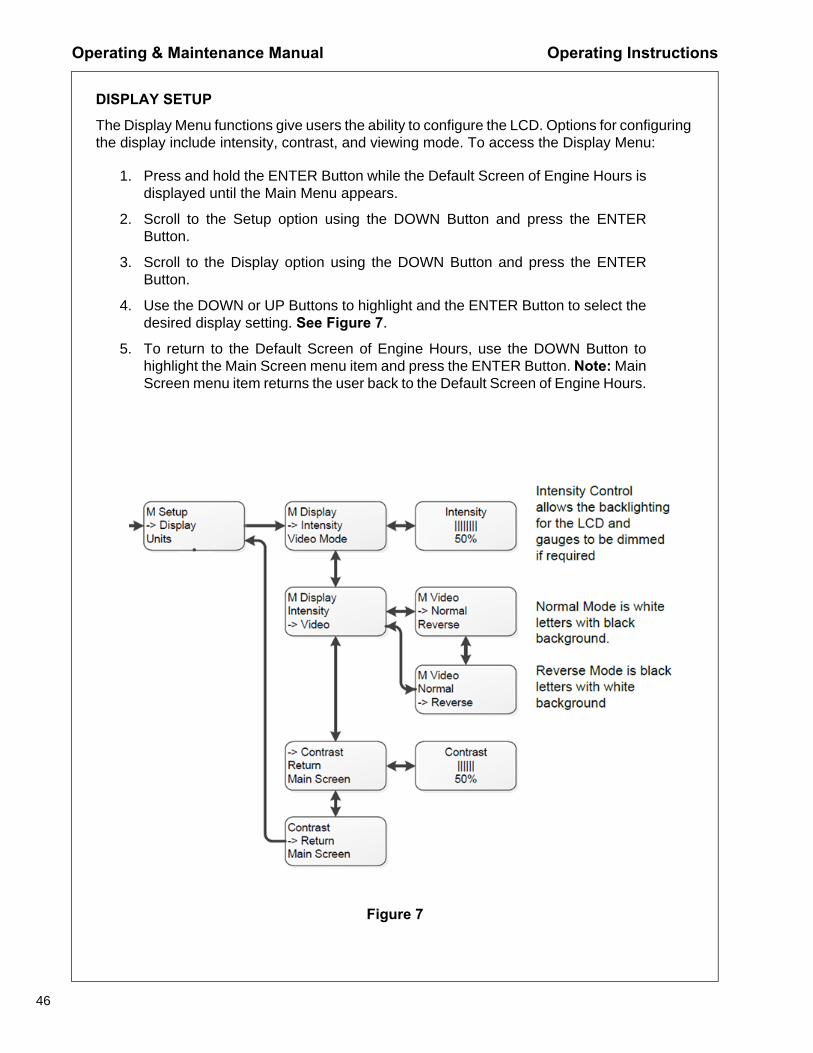
The Display Menu functions give users the ability to configure the LCD. Options for configuring the display include intensity, contrast, and viewing mode. To access the Display Menu:
1. Press and hold the ENTER Button while the Default Screen of Engine Hours isdisplayed until the Main Menu appears.
2. Scroll to the Setup option using the DOWN Button and press the ENTERButton.
3. Scroll to the Display option using the DOWN Button and press the ENTERButton.
4. Use the DOWN or UP Buttons to highlight and the ENTER Button to select thedesired display setting. See Figure 7.
5. To return to the Default Screen of Engine Hours, use the DOWN Button tohighlight the Main Screen menu item and press the ENTER Button. Note: MainScreen menu item returns the user back to the Default Screen of Engine Hours.
The Compressor Control System has a power save feature designed to prevent drain on the batteries when the compressor engine is not running. If the Control Panel is powered ON and the engine has not run for 3 minutes (above 45°F (7°C) or 15 minutes at or below 45°F (7° C)), the control system will automatically power OFF. Power can be restored by pressing the Main Power Button.
In the event of a fault, this feature is not active and the power will remain on until the fault has been acknowledged or the control system is manually powered off.
WAIT TO START
When the Main Power Button is pressed, the display will initialize and the Wait to Start message will be displayed. While the Wait to Start message is displayed, the engine will receive heat from the intake heater if required. It is best to start the engine immediately after the Wait to Start message changes to Engine Total Hours.
Lifting
The central lifting bail allows the compressor to be lifted from a single point. Use hoist or crane capable of lifting compressor weight (See General Data).
WARNING!
Falling off the compressor can cause serious injury or death. Use ladder and handholds to access lifting bail.
Before Towing
Ensure the tires, wheels and running gear are in good condition and secure.
High Speed Running Gear
• Use jack to raise or lower drawbar.
• Use tow vehicle whose towing capacity is greater than the weight of the compressor(See General Data).
• Do not tow the compressor in excess of the maximum towing speed (See GeneralData).
• Place wheel chocks under tires and/or set parking brake before disconnecting fromtowing vehicle.
• When raising or lowering drawbar, always stand to one side.
Setting Up Place the compressor in an open, well-ventilated area. Ensure sufficient clearance for ventilation and exhaust requirements. Adequate clearance needs to be allowed around and above the compressor to permit safe access for specified maintenance tasks.
Position as level as possible. Do not exceed the out-of-level operating limit (See General Data).
When the compressor is to be operated out-of-level, it is important: (1) to keep the engine oil level near the high level mark (with the compressor level), and (2) to have the compressor oil level gauge show no more than mid-scale (with the compressor running at full load). Do not overfill either the engine oil or the compressor oil.
Ensure the compressor is positioned securely and on a stable foundation. Any risk of movement should be removed by suitable means, especially to avoid strain on air discharge piping.
Chock wheels and/or set parking brake.
Ensure all transport and packing materials are removed.
Compressor MountingPortable compressors, which are modified to remove the running gear and mount the compressor directly to trailers, truck beds, or frames, etc. may experience failure of the enclosure, frame, and/or other components. It is necessary to isolate the compressor package from the carrier base with a flexible mounting system. Such a system must also prevent detachment of the package from the carrier base in the event the isolators fail. Contact your Portable Power representative for flexible mounting kits.
Warranty does not cover failures attributable to mounting of the compressor package to the carrier base unless it is a Portable Power provided system.
Service Air Connection(s)
WARNING!
All air pressure equipment installed in or connected to the compressormust have safe working pressure ratings of at least the safety valvesetting and materials compatible with the compressor oil (Refer to theGeneral Data).
Do not connect the air discharge on this compressor onto a commonheader with any other unit of any description, or any other source ofcompressed air, without first ensuring a check-valve is used between theheader and the compressor. If this compressor is connected in parallelwith another compressor of higher discharge pressure and capacity asafety hazard could occur in a back-flow condition.
WARNING!
Unrestricted air flow from a hose will result in a whipping motion of thehose which can cause serious injury or death. A safety device must beattached to the hose at the source of supply to reduce pressure in caseof hose failure or other sudden pressure release. Reference: OSHAregulation 29 CFR Section 1926.302 (b).
Air Hose Restraint InstallationSafety devices such as hose restraints (whipchecks) must be used to prevent hose whipping if a connection fails. Whipchecks are to be constructed of woven stainless steel, galvanized steel wire rope, or chain with a minimum strength adequate for the supplied pressure and hose diameter. Whipchecks must be fastened to suitable mounting points or shackles.
The mounts and/or shackles are to be of the same or greater strength as the whipchecks. An engineer should be consulted about suitability of whipchecks, mounts, mounting points, shackles, and fittings as well as strength rating of materials. Whipchecks must be used at the hose origination, termination, and each hose to hose connection.
Hoses can fail in areas other than at connecting points and require daily inspection of the hoses for:
• Cuts, cracks, or kinks
• Weakened clamps due to rust and corrosion
• Damaged connections
• Deformity
• Incorrect or incompatible components or fittings
• Any visual damage
Hoses must be selected that are rated for the application as to the maximum pressure and temperature to be encountered as well as compatible with the materials being conveyed inside the hose. Hoses must be compatible with the compressor oil.
Before StartingOpen Manual Blowdown Valve to ensure the separator tank has been vented of all pressure. Close the valve before starting. Inspect the complete installation including remote fuel lines (if any) and air hose routing and connections. Check battery for proper connections and condition.
WARNING!
Combustible gas can cause severe burns, blindness, or death. Keepsparks and open flame away from battery.
Check the compressor oil level. Maintain the oil level between bottom and midway of the sight glass on the separator tank.
Check engine oil level. The proper level is labeled on the engine dipstick. Add oil when required. Do not overfill.
CAUTION!
Exercise extreme caution when using an external method to jumpstart aunit. Verify the electrical systems on the weak battery system and theexternal jump system are the same voltage type system, 12VDC or24VDC. Connect the Positive (+) terminal of the external system to thePositive (+) terminal on the weak system. Connect the Negative (-)terminal of the external system to the Negative (-) terminal of the weaksystem. Always disconnect the two systems in reverse order.
WARNING!
Do not remove the pressure cap from a HOT engine radiator. The suddenrelease of pressure from a heated cooling system can result in a loss ofcoolant and possible severe personal injury.
WARNING!
Hot pressurized fluid can cause serious burns. Do not open radiator whilehot.
Check coolant to ensure coolant level is at or above minimum level when the engine is cold. Check engine coolant level at radiator pressure cap. Add coolant as required. Ensure pressure cap is installed properly and tightened.
NOTICEIf the appropriate mixture of antifreeze is not used during freezingtemperatures, failure to drain the engine may cause costly enginedamage. Never use water only, as corrosion inhibitors are required inengine coolant fluid.
CAUTION!
No smoking, sparks, or open flame near fuel.
Check the fuel level and add fuel as necessary. Ultra-low sulfur diesel fuel (ULSD), with a maximum sulfur content of 15 ppm is required. If ultra-low sulfur diesel is not used, the engine could possibly not meet emissions regulations and the engine or aftertreatment system may be damaged. Refer to the Engine Operator Manual for fuel specifications.
NOTICETo minimize condensation (water) in the fuel tank, it is recommended tofill the tank at the end of each day.
NOTE: Compressor will not allow engine starting if the fuel level is belowthe minimum fuel shut off level.
WARNING!
Compressor produces loud noise with doors open. Extended exposure toloud noise can cause hearing loss. Wear hearing protection when doorsor valve(s) are open.
Close the doors to maintain a cooling air path and to avoid recirculation of hot air. This will maximize the life of the engine and compressor and protect the hearing of surrounding personnel.
Ensure no one is IN or ON the compressor.
Ensure that the location of the Emergency Stop Button (if equipped) is known and recognized by its markings. Ensure that it is functioning correctly and that the method of operation is known.
Ensure that the access panels for heat exchanger cleaning are closedand secure before starting the compressor. Rotating fan blades cancause serious injury or death. Do not operate without all guards in place.
Starting
CAUTION!
Do not use ether or any other starting fluid. Starting fluids can cause anexplosion, fire, and severe engine damage. The engine is equipped withan electric heater starting aid.
NOTICEThis compressor is equipped with a battery disconnect switch whichdisconnects power for long term storage. The switch is located on thefuel tank side.
This switch must be in the ON position to provide power to the ControlPanel for starting the compressor.
1. Press the Main Power Button.
2. When the Wait To Start message on the MidPort changes to Total EngineHours =, press and release Green Start Button .
3. Engine will crank until engine starts or engine starting time limit is reached. Thefirst Green light on the Start Button will illuminate.
4. If engine fails to start, press Main Power Button to remove power fromengine, then repeat steps 1-3.
5. When engine starts, the first two lights on the Start Button will illuminate.
6. Wait for Engine Temperature to reach 150°F (65°C). Press Service AirButton. The third light on the Start Button will illuminate.
7. The compressor will start in the Low Pressure Mode and the Low PressureLight will be illuminated on the Low Pressure Button.
8. To change to the High Pressure Mode, press the High Pressure Button. Threelights on the button will illuminate.
To ensure an adequate flow of oil to the airend, never allow the discharge pressure to fall below 50 psi.
Normal Operation The operator may observe and monitor operating parameters using the MidPort and gauges. In the event the compressor controller detects a parameter outside normal operating limits, the compressor will alert and/or shutdown, and display a diagnostic code.
In the event the compressor controller detects a parameter at a dangerously high or low level, the compressor will be automatically shut down with the cause of the shutdown shown on the MidPort.
Two Pressure Modes of Operation
The compressor is capable of operating at two pressure modes:
1. The Low Pressure Mode is activated by pressing the Lo Pressure Button. In thismode, the compressor will regulate according to the air demand, between 0 and rated airdelivery (See General Data) at the lower regulated set pressure (See General Data). Theregulated set pressure of this mode can be regulated as low as 80 psi.
2. The High Pressure Mode is activated by pressing the Hi Pressure Button. In HighPressure Mode, the compressor will regulate according to air demand, between 0 and ratedair delivery (See General Data) at the higher regulated set pressure (See General Data). Theregulated set pressure of this mode can be regulated as low as 80 psi.
The mode of the compressor can be changed between the Low and High at anytime. Enginespeed will be lower at the HI Pressure Mode setting.
Operation - Loaded
Assume engine has been started and is running in the unload state at idle speed. If there is air demand (pressure falls below the load point pressure), compressor will load at idle speed by opening the inlet valve. As air demand rises and falls, engine speed is controlled between idle speed and full load speed to match the required flow while maintaining load point pressure.
Operation - UnloadedIf there is no air demand at idle speed (pressure rises above the unload point pressure), the compressor will unload by closing the inlet valve. The compressor then runs at idle speed unloaded with no air delivery. If air demand increases (pressure falls below the load point pressure), the compressor reloads to meet the required air demand.
2. Allow the engine to idle for 3 minutes to cool down.
3. Press the Red Stop Button.
4. Press the Main Power Button xxxxxxxxx when use of the compressor is notneeded.
Note: Until Main Power Button is pressed, the gauges can be read and the MidPortcan be navigated using the UP, DOWN, and ENTER Buttons.
5. If the Main Power Button is not pressed within 3 minutes (if ambienttemperature is above 45°F (7°C) or 15 minutes if ambient temperature is 45°F(7°C) or below of the keypad use the compressor will automatically shut off.
NOTICEFailure to allow turbocharger cool down prior to stopping can causeturbocharger damage.
NOTICEThis compressor is equipped with a battery disconnect switch whichdisconnects power for long term storage. The switch is located on thefuel tank side.
Do not use the battery disconnect switch for normal stopping. Wait 1minute after stopping engine before turning the battery disconnectswitch to the OFF position.
CAUTION!
Use the Emergency Stop, if equipped, only for emergency conditions. Donot use for normal stopping. Emergency Stop must be reset beforestarting can be accomplished.
NOTICEOnce the engine stops, the Automatic Blowdown Valve will relievepressure from the separator tank. If the Automatic Blowdown Valve failsto operate, pressure must be relieved from the system by means of theManual Blowdown Valve.
WARNING!
Pressure will remain in the system between the Minimum Pressure Valveand the Service Valve after shutdown and operation of the AutomaticBlowdown Valve. This pressure must be relieved by disconnecting anydownstream equipment and opening the Discharge Valve to atmosphere.
CAUTION!
Never allow the compressor to sit stopped with pressure in the separatortank or piping. As a precaution, open the Service Valve.
DecommissioningWhen the compressor is to be permanently decommissioned or dismantled, it is important to ensure that all hazard risk are either eliminated or recepient of the compressor notified. In particular:
• Do not destroy batteries or components containing asbestos without containing thematerials safely.
• Do not dispose of any pressure vessel that is not clearly marked with its relevant dataplate information or rendered unusable by drilling, cutting, etc.
• Do not allow lubricants or coolants to be released into land surfaces, water, or drains.
• Do not dispose of a complete compressor without documentation relating toinstructions for its use.
This section refers to the various components which require periodic maintenance and replacement.
The Maintenance Schedule indicates the various components' descriptions and the intervals when maintenance has to take place. Fluid capacities can be found in the General Data Section of this manual. For any specification or specific requirement on service or preventative maintenance for the engine, refer to the Engine Manual.
Compressed air can be dangerous if incorrectly handled. Review all maintenance precautions listed below before attempting any maintenance work on the compressor.
Maintenance PrecautionsPrior to attempting any maintenance work, ensure:
1. All pressure is vented from the system and the compressor cannot be startedaccidentally.
2. If the Automatic Blowdown Valve fails to operate, pressure must be graduallyrelieved by operating the Manual Blowdown Valve.
3. The discharge pipe/manifold area is depressurized by opening the dischargevalve while keeping clear of any air flow.
4. Maintenance personnel are adequately trained, competent, and have read theOperation and Maintenance Manual.
WARNING!
Pressure will remain in the system between the Minimum Pressure Valveand the Service Valve after shutdown and operation of the AutomaticBlowdown Valve. This pressure must be relieved by disconnecting anydownstream equipment and opening the discharge valve to atmosphere.
Prior to opening or removing panels or covers inside a compressor, ensure:
1. Anyone entering the compressor is aware of the reduced level of protection andthe additional hazards, including hot surfaces and intermittently moving parts.
2. The compressor cannot be started. Post warning signs and/or fit anti-startdevices.
3. Battery cables are disconnected.
Maintenance Operation & Maintenance Manual
59
Prior to attempting any maintenance work on a running compressor, ensure:
1. The work carried out is limited to only those tasks which require the compressorto run.
2. The work carried out with safety protection devices disabled or removed islimited to only those tasks which require the compressor to be running withsafety protection devices disabled or removed.
3. All hazards present are known (e.g. pressurized components, electrically livecomponents, removed panels, covers and guards, extreme temperatures,inflow and outflow of air, intermittently moving parts, safety valve discharge).
4. Appropriate personal protective equipment is worn.
5. Loose clothing, jewelry, long hair etc. is made safe.
6. Warning signs indicating that Maintenance Work is in Progress are posted in aposition that can be clearly seen.
Upon completion of maintenance task and prior to returning the compressor into service, ensure:
1. The compressor is suitably tested.
2. All guards and safety protection devices are refitted.
3. All panels are replaced, canopy and doors closed.
4. Hazardous materials are effectively contained and disposed of.
NOTICEThe maintenance schedule in this manual describes the service intervalsthat should be followed for normal applications of this compressor. Thispage may be reproduced and used as a checklist by service personnel.
In more severe applications (i.e., sandblasting, quarry drilling, welldrilling, and oil and gas drilling) more frequent service intervals will berequired to ensure long component life.
Dust and dirt, high humidity, and high temperatures will affect lubricantlife and service intervals for components such as inlet air filters, oilseparation elements, and oil filters.
Operation & Maintenance Manual Maintenance
60
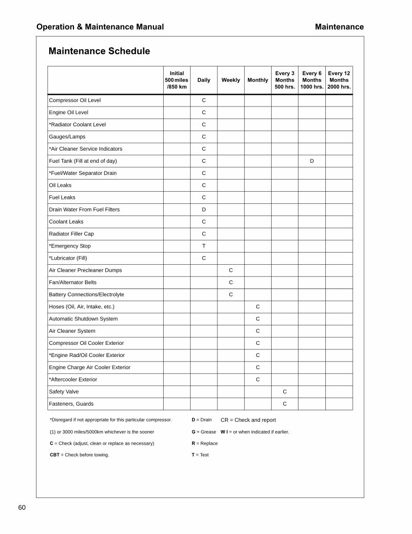
Maintenance Schedule
Initial 500 miles /850 km
Daily Weekly MonthlyEvery 3 Months 500 hrs.
Every 6 Months
1000 hrs.
Every 12 Months
2000 hrs.
Compressor Oil Level C
Engine Oil Level C
*Radiator Coolant Level C
Gauges/Lamps C
*Air Cleaner Service Indicators C
Fuel Tank (Fill at end of day) C D
*Fuel/Water Separator Drain C
Oil Leaks C
Fuel Leaks C
Drain Water From Fuel Filters D
Coolant Leaks C
Radiator Filler Cap C
*Emergency Stop T
*Lubricator (Fill) C
Air Cleaner Precleaner Dumps C
Fan/Alternator Belts C
Battery Connections/Electrolyte C
Hoses (Oil, Air, Intake, etc.) C
Automatic Shutdown System C
Air Cleaner System C
Compressor Oil Cooler Exterior C
*Engine Rad/Oil Cooler Exterior C
Engine Charge Air Cooler Exterior C
*Aftercooler Exterior C
Safety Valve C
Fasteners, Guards C
*Disregard if not appropriate for this particular compressor. D = Drain CR = Check and report
(1) or 3000 miles/5000km whichever is the sooner G = Grease W I = or when indicated if earlier.
C = Check (adjust, clean or replace as necessary) R = Replace
CBT = Check before towing. T = Test
Maintenance Operation & Maintenance Manual
61
Initial 500 miles /850 km
Daily Weekly MonthlyEvery
6Months 500 hrs.
Every 12 Months 1000 hrs
Every 48 Months5000 hrs
Air Cleaner Elements R/WI
*Fuel/Water Separator Element R
Fuel Filter Element R
Engine Oil Change R
Engine Oil Filter R
*Engine Coolant Cond. Element R
Compressor Oil Filter Element R
Compressor Oil R
Oil Separator Element R
Separator Tank Exterior (2) CR
*Engine Coolant C R
Engine Crankcase Breather Element
R
*Water Pump Grease. G
Shutdown Switch Settings T
Scavenge Orifice & Related Parts C
Scavenge Line C
*Valve Clearance Check C
*Feed Pump Strainer Cleaning C
*Injection Nozzle Check C
*Disregard if not appropriate for this particular compressor. D = Drain
(1) or 3000 miles/5000km whichever is the sooner G = Grease
(2) or as defined by local or national legislation R = Replace
C = Check (adjust, clean or replace as necessary) T = Test
CBT = Check before towing. W I = or when indicated if earlier.
CR = Check and report
Operation & Maintenance Manual Maintenance
62
Initial 500 miles /850 km
Daily Weekly Monthly 3 Months 500 hrs.
6 Months 1000 hrs
12 Months2000 hrs
*Brake linkage C C
*Brakes C C
*Lights (running, brake, & turn) CBT
*Pintle Eye Bolts CBT
*Tire Pressure and Condition C
*Wheel Lug Nuts C
*Running gear linkage G
*Running gear bolts(1) C
*Wheels (Bearings, Seals, etc.) C G
2 Yrs 4 Yrs 6 Yrs
Safety valve C
Hoses R
Separator tank (2) interior C
*Disregard if not appropriate for this particular compressor. D = Drain
(1) or 3000 miles/5000km whichever is the sooner G = Grease
(2) or as defined by local or national legislation R = Replace
C = Check (adjust, clean or replace as necessary) T = Test
CBT = Check before towing. W I = or when indicated if earlier.
CR = Check and report Refer to specific sections of the operator's manual for more information.
Maintenance Operation & Maintenance Manual
63
Scavenge LineThe scavenge line runs from the combined orifice/check valve at drop tube in the separator tank to the fitting located in the airend.
Check that the scavenge line and tube are clear of any obstruction. Refer to the Maintenance Schedule for recommended servicing intervals. Any blockage will result in oil carryover into the discharge air.
Compressor Oil FilterRefer to the Maintenance Schedule for the recommended servicing intervals.
Removal
WARNING!
Do not remove the filter(s) without first ensuring the compressor is shutoff and the system has been completely relieved of all air pressure. (Referto STOPPING in the OPERATING INSTRUCTIONS section of this manual).
Clean the exterior of the filter housing and remove the spin-on element.
lnspectionInspect the oil filter head to be sure the gasket was removed with the oil filter element. Clean the gasket seal area on the oil filter head.
CAUTION!
If there is any indication of the formation of varnishes, shellacs, orlacquers on the filter element, it is a warning that the compressorlubricating and cooling oil has deteriorated and should be changedimmediately. Refer to LUBRICATION section.
NOTICEInstalling a new oil filter element when the old gasket remains on the filterhead will cause an oil leak and can cause property damage.
ReassemblyClean the filter gasket contact area and install the new element. Tighten until the gasket makes contact with the filter housing. Tighten an additional 1/2 to 3/4 of a revolution.
Operation & Maintenance Manual Maintenance
64
CAUTION!
Start the compressor (refer to BEFORE STARTING and STARTING in theOPERATING INSTRUCTIONS section of this manual) and check forleakage before the compressor is put back into service.
Compressor Oil Separator ElementRefer to the Maintenance Schedule in this section for the recommended servicing intervals. If the element has to be replaced, then proceed as follows:
Removal
WARNING!
Do not remove the filter(s) without first ensuring the compressor is shutoff and the system has been completely relieved of all air pressure. (Referto STOPPING in the OPERATING INSTRUCTIONS section of this manual).
Disconnect all hoses and tubes from the separator tank cover plate. Remove the drop tube from the separator tank cover plate and remove the cover plate. Remove the separator element.
lnspection
Examine the separator element. Examine all hoses and tubes, and replace if necessary.
Reassembly
Thoroughly clean the orifice/drop tube and filter gasket contact area before reassembly. Install the new element.
WARNING!
DO NOT remove the staple from the anti-static gasket on the separatorelement since it serves to ground any possible static build-up. DO NOTuse gasket sealant since this will affect electrical conductance.
Maintenance Operation & Maintenance Manual
65
Reposition the cover plate, taking care not to damage the gasket. Replace the cover plate screws tightening in a criss-cross pattern to the recommended torque (refer to the torque values in this section).
Reconnect all hoses and tubes to the separator tank cover plate.
Replace the compressor oil (refer to LUBRICATION section).
CAUTION!
Start the compressor (refer to BEFORE STARTING and STARTING in theOPERATING INSTRUCTIONS section of this manual) and check forleakage before the compressor is put back into service.
Compressor Oil Cooler, Engine Radiator, and other Heat ExchangersWhen grease, oil, and dirt accumulate on the exterior surfaces of the heat exchangers, the efficiency is impaired. It is recommended that the heat exchangers be cleaned per the Maintenance Schedule in this manual by a jet of compressed air. This should remove any accumulation of oil, grease, and dirt from the exterior cores of the cooler so the entire cooling area can radiate heat into the air stream. Access doors are located on each side of the compressor to provide access to aid in cleaning the heat exchangers.
WARNING!
Ensure the heat exchanger access doors are closed and secure beforestarting the engine.
WARNING!
Hot engine coolant and steam can cause injury. When adding coolant orantifreeze solution to the engine radiator, stop the engine and allowradiator to cool prior to releasing the radiator pressure cap. Using a clothto protect the hand, slowly release the pressure cap, absorbing anyreleased fluid with the cloth. Do not remove the pressure cap until allexcess fluid is released and the engine cooling system fullydepressurized.
Operation & Maintenance Manual Maintenance
66
WARNING!
Follow the instructions provided by the antifreeze supplier when addingor draining the antifreeze solution. It is advisable to wear personalprotective equipment to prevent skin and/or eye contact with theantifreeze solution.
Air Filter ElementsThe air filter elements should be replaced regularly (refer to the Maintenance Schedule) or when indicated on the Control Panel, whichever comes first. The aircleaner precleaner dumps should be cleaned as indicated in the Maintenance Schedule (more frequently in dusty operating conditions).
Removal
CAUTION!
Never remove and replace element(s) when the compressor is running.
Clean the exterior of the filter housing and remove the filter element by following instructions on the filter.
If the safety element is to be replaced, thoroughly clean the interior of the filter housing prior to removing the safety element.
Inspection
Check for cracks, holes, or any other damage to the element by holding it up to a light source or by passing a lamp inside.
CAUTION!
If inspection reveals damage to the main element, the safety elementmust be replaced.
Check the seal at the end of the element and replace if any sign of damage is evident.
Reassembly
Assemble the new element into the filter housing ensuring the seal seats properly. Secure element following instructions on the filter.
Before restarting the compressor, ensure all clamps are tight.
Maintenance Operation & Maintenance Manual
67
VentilationEnsure air inlets and outlets are clear of debris etc.
Cooling Fan DriveEvery 3 months check to ensure fan drive mounting bolts to the engine have not loosened. If, for any reason, it becomes necessary to remove or re-tighten the mounting bolts, apply a good grade of commercially available thread locking compound to the bolt threads and tighten to 23Nm (17 ft-lbF) of torque.
The fan belt(s) should be checked monthly for wear and correct tensioning.
This compressor is equipped with a variable speed fan clutch and requires no periodic maintenance.
Fuel SystemThe fuel tank(s) should be filled daily or every eight hours. To minimize condensation in the fuel tank(s), it is advisable to top up after the compressor is shut down or at the end of each working day. Drain any sediment or condensate that may have accumulated in the tank(s). Refer to Maintenance Schedule.
Fuel Filter Water SeparatorThe fuel filter water separator contains a filter element which should be replaced as required by the Maintenance Schedule.
Charge Air Cooler PipeworkForeign particles can damage the engine and turbocharger. Maintain internal cleanliness and integrity of the air filtration, intake piping, and charge air cooler piping to help avoid damage. Monthly inspect systems for leaks and that hoses, clamps, and connections are sealed. Check for damaged or deteriorated components. Pay careful attention to keep the internal surfaces clean, particularly when parts are removed for inspection or service.
HosesAll components of the fuel, engine cooling, and air intake system should be checked monthly to keep the engine at peak efficiency.
At the recommended intervals, (see the Maintenance Schedule), inspect all of the intake lines to the air filter, and all flexible hoses used for air lines, oil lines, and fuel lines.
Every 3 months inspect all pipework for cracks, leaks, etc. and replace immediately if damaged.
Operation & Maintenance Manual Maintenance
68
Electrical System
WARNING!
Disconnect the battery cables before performing any maintenance orservice.
Check the security of electrical devices and sensors to ensure terminals and/or connectors are tight. Loose connections may cause local hot spot oxidation.
When removing connectors from electrical devices and sensors, inspect the terminals to ensure they have electrical grease on them. If electrical grease is not present or very minimal, add a small amount of Doosan Part No. 22409114 Electrical Grease to the terminals.
Dirty and/or corroded electrical terminals can be cleaned using electrical contact cleaner.
Inspect the components and wiring for signs of overheating (i.e., discoloration, charring of cables, deformation of parts, acrid smells, and blistered paint).
BatteryKeep the battery terminals and cable clamps clean and lightly coated with petroleum jelly to prevent corrosion. The battery restraint should be kept tight enough to prevent the battery from moving.
Pressure SystemRegularly, it is necessary to inspect the external surfaces of the pressure system, from the Airend through to the Service Valve(s) including hoses, tubes, tube fittings, and the separator tank for visible signs of impact damage, excessive corrosion, abrasion, tightness, and chafing. Any suspect parts should be replaced before the compressor is put back into service.
Tire PressureSee the General Data Section of this manual.
Running Gear/WheelsCheck wheel nut torque 20 miles (30 kilometers) after refitting the wheels. Refer to Torque Values later in this section.
Lifting jacks should only be used under the axle.
Bolts securing the running gear to the chassis should be checked for tightness (refer to the Maintenance Schedule for frequency). Re-tighten where necessary. Refer to Torque Values later in this section.
Maintenance Operation & Maintenance Manual
69
Lubrication
CAUTION!
Always check the oil levels before a new compressor is put into service.
If, for any reason, the compressor oil has been drained, it must be re-filled with new oil before putting into operation.
Engine Oil
The engine oil and oil filter element should be changed at the engine manufacturer's recommended intervals. Refer to the Engine Operator Manual.
The Tier 4 engine in this compressor requires engine lubricating oil to ensure proper Aftertreatment System operation and engine durability. Doosan Tier 4 Premium Engine Oil is recommended. Refer to the Engine Operator Manual for engine oil specifications.
Compressor Oil
Refer to the Maintenance Schedule in this section for service intervals.
NOTE: If the compressor has been operating under adverse conditions orhas suffered long shutdown periods, more frequent service intervals willbe required.
WARNING!
DO NOT, under any circumstances, remove any drain plugs or the oil fillerplug from the compressor lubricating and cooling system without firstensuring the compressor is stopped and the system has been completelyrelieved of all air pressure (refer to STOPPING in the OperatingInstructions Section of this manual).
Completely drain the separator tank, piping, and oil cooler by removing the drain plug(s) and collecting the used oil in a suitable container.
Replace the drain plug(s) ensuring that each one is secure.
NOTE: If the oil is drained immediately after the compressor has been in operation,most of the sediment will be in suspension and will drain more readily.
Operation & Maintenance Manual Maintenance
70
CAUTION!
Some oil mixtures are incompatible and result in the formation ofvarnishes, shellacs, or lacquers which may be insoluble. Refer to thePortable Compressor Oil Chart.
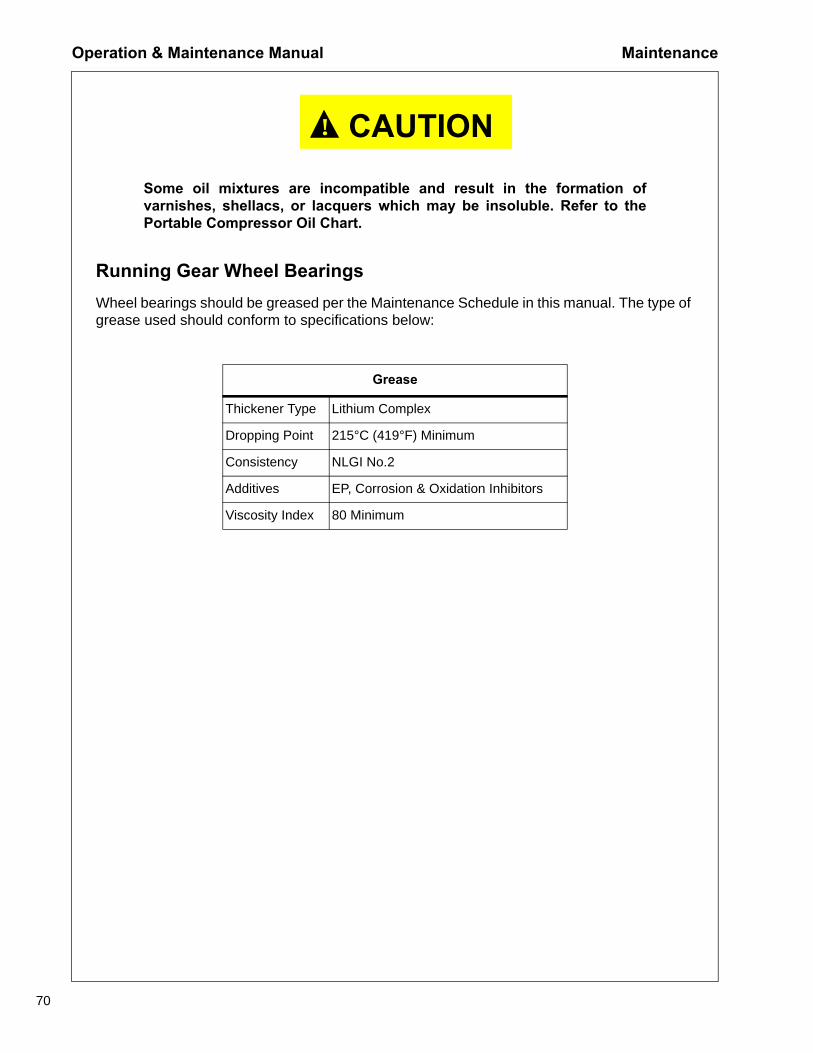
Running Gear Wheel BearingsWheel bearings should be greased per the Maintenance Schedule in this manual. The type of grease used should conform to specifications below:
Grease
Thickener Type Lithium Complex
Dropping Point 215°C (419°F) Minimum
Consistency NLGI No.2
Additives EP, Corrosion & Oxidation Inhibitors
Viscosity Index 80 Minimum
Maintenance Operation & Maintenance Manual
71
Pressure Regulator Adjusting Instructions
Before Starting
1. Select Low Pressure Mode by pressing the LO Pressure Button.
2. At the Low Pressure Regulator, loosen the jam nut and turn screw counterclockwise until tension is no longer felt at the screw. Turn screw clockwise one full turn.
3. If high pressure regulation needs adjustment, repeat Step 2 at High Pressure Regulator.
4. Close Service Valves.
After Starting Unit
5. Push the Service Air Button on the Control Panel. The unit should speed up and then unload (and drop back to IDLE). With the unit unloaded, turn the adjusting screw on the Low Pressure Regulator clockwise until the discharge pressure gauge indicates 25 psi over the rated pressure. Tighten the pressure regulator jam nut.
6. To adjust the high pressure regulation, repeat Step 5 on High Pressure Regulator except adjust pressure at idle to 25 psi over the rated pressure while in High Pressure Mode.
Note: The High Pressure Regulator must be set at a higher pressure than the Low Pressure Regulator.
Low Pressure Regulator High Pressure Regulator
Operation & Maintenance Manual Maintenance
72
Torque Values
TABLE 1 INCH FASTENERS
SAEJ249 SAEJ249
Maintenance Operation & Maintenance Manual
73
Note: Cooling Fan Drive Bolts (10.9 M8x1.25) should be torqued to 23Nm (17ft-lbF).
Wheel Torque Chart - Inch Wheel Torque Chart - Metric
General InformationLubrication is an essential part of preventive maintenance, affecting to a great extent the useful life of the compressor. Different lubricants are needed and some components require more frequent lubrication than others. Therefore, it is important that the instructions regarding types of lubricants and the frequency of their application be explicitly followed. Periodic lubrication of the moving parts reduces to a minimum the possibility of mechanical failures.
The Maintenance Schedule shows those items requiring regular service and the interval in which they should be performed. A regular service program should be developed to include all items and fluids. These intervals are based on average operating conditions. In the event of extremely severe (hot, cold, dusty, or wet) operating conditions, more frequent lubrication than specified may be necessary.
All filters and filter elements for air and compressor oil must be obtained through Portable Power to ensure the proper size and filtration for the compressor.
Compressor Oil ChangeThese compressors are furnished with an initial supply of oil sufficient to allow operation until the first service interval indicated in the Maintenance Schedule. If a compressor has been drained of all oil, it must be refilled with new oil before it is placed in operation. Refer to specifications in the Portable Compressor Oil Chart.
NOTICESome oil types are incompatible when mixed and result in the formationof varnishes, shellacs, or lacquers which may be insoluble. Suchdeposits can cause serious troubles including clogging of the filters. DONOT mix oils of different types and avoid mixing different brands. A typeor brand change is best made at the time of a complete oil drain and refill.
If the compressor has been operated for the time/hours indicated in the Maintenance Schedule, it should be drained of oil. If the compressor has been operated under adverse conditions, or after long periods in storage, an earlier change may be necessary as oil deteriorates with time as well as by operating conditions.
CAUTION!
In most severe applications (i.e., sandblasting, quarry drilling, welldrilling, and oil and gas drilling) more frequent service intervals will berequired to ensure long component life.
Lubrication Operation & Maintenance Manual
77
WARNING!
High pressure air can cause severe injury or death from hot oil and flyingparts. Always relieve pressure before removing caps, plugs, covers, orother parts from pressurized air system. Ensure that the air pressuregauge reads zero (0) pressure and ensure there is no air discharge whenopening the manual blowdown valve.
An oil change is good insurance against the accumulation of dirt, sludge, or oxidized oil products.
Completely drain the separator tank, piping, and cooler. Note: If the compressor has been operating under adverse conditions or has suffered long shutdown periods, more frequent service intervals will be required. If the oil is drained immediately after the compressor has been run for some time, most of the sediment will be in suspension and, therefore, will drain more readily. However, the oil will be hot and care must be taken to avoid contact with the skin or eyes.
After the compressor has been drained of all old oil, close the drain valves and/or plugs and install new oil filter elements. Add oil in the specified quantity at the filler plug. Tighten the filler plug and run the compressor to circulate the oil. Check the oil level. DO NOT OVERFILL.
NOTICEPortable Power provides compressor oil specifically formulated forPortable Compressors. Use of these fluids is required to obtain extendedlimited airend warranty.
Operation & Maintenance Manual Lubrication
78
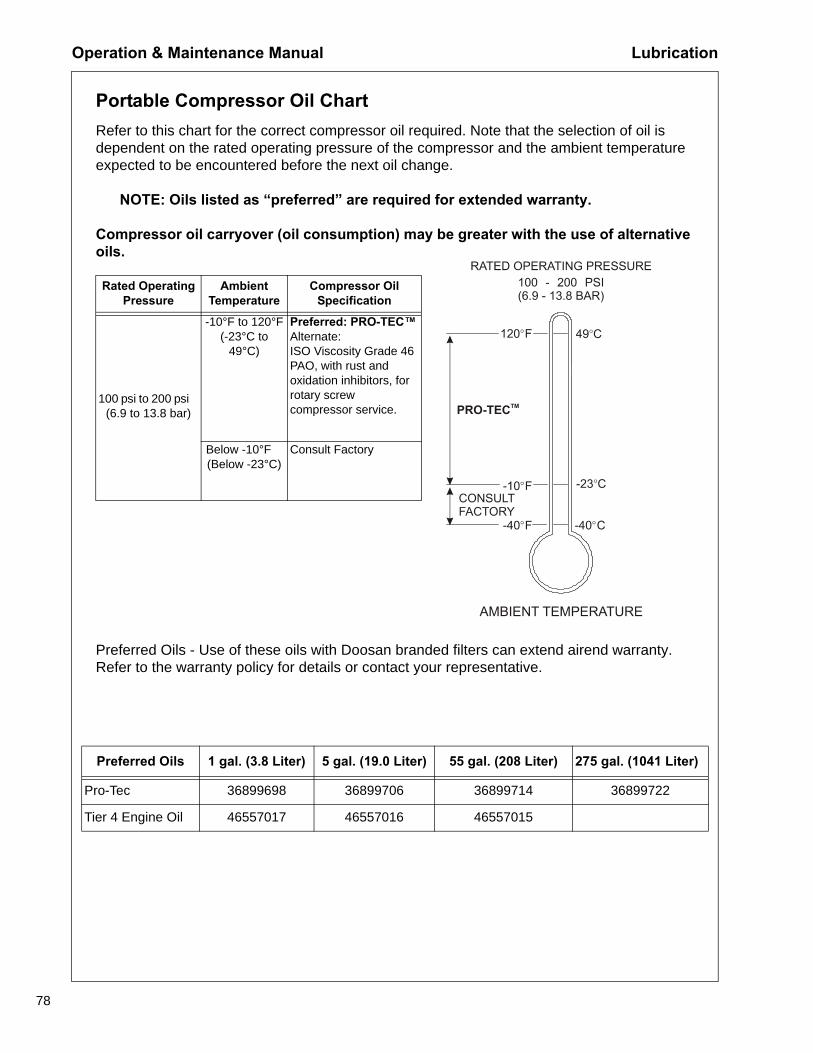
Portable Compressor Oil ChartRefer to this chart for the correct compressor oil required. Note that the selection of oil is dependent on the rated operating pressure of the compressor and the ambient temperature expected to be encountered before the next oil change.
NOTE: Oils listed as “preferred” are required for extended warranty.
Compressor oil carryover (oil consumption) may be greater with the use of alternative oils.
Preferred Oils - Use of these oils with Doosan branded filters can extend airend warranty. Refer to the warranty policy for details or contact your representative.
Table 1:
Rated Operating Pressure
Ambient Temperature
Compressor Oil Specification
100 psi to 200 psi ( (6.9 to 13.8 bar)
-10°F to 120°F(-23°C to
49°C)
Preferred: PRO-TEC™Alternate:ISO Viscosity Grade 46 PAO, with rust and oxidation inhibitors, for rotary screw compressor service.
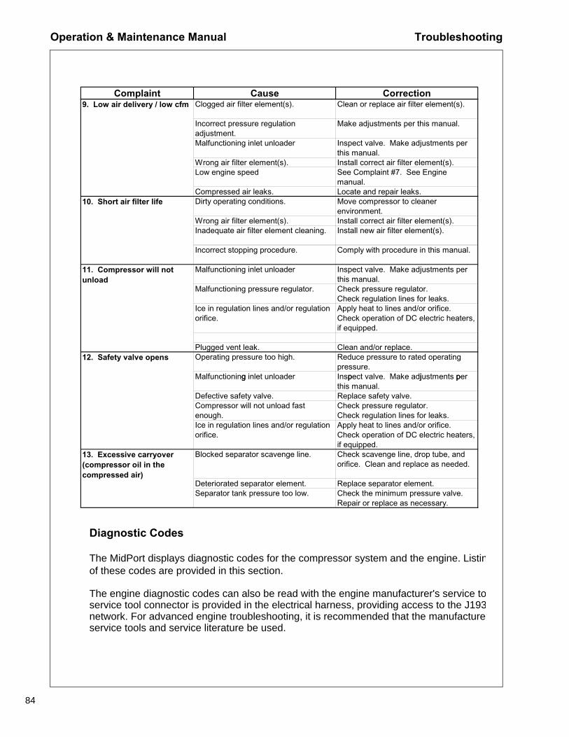
Troubleshooting for a portable air compressor is an organized study of a particular problem or series of problems and a planned method of procedure for investigation and correction. The troubleshooting chart that follows includes some of the problems that an operator may encounter during the operation of a portable compressor.
The chart does not attempt to list all of the complaints that may occur, nor does it attempt to give all of the solutions for correction of the complaints. The chart does list the complaints that are most likely to occur. To use the Troubleshooting Chart:
A. Find the complaint depicted as a bold heading.
B. Follow down that column to find the potential cause or causes. The causes arelisted in order to suggest an order to follow in troubleshooting.
Think Before ActingStudy the problem thoroughly and ask yourself these questions:
1. What were the warning signals that preceded the problem?2. Has a similar problem occurred before?3. What previous maintenance work has been done?4. If the compressor will still operate, is it safe to continue operating to make
further checks?
Do the Simplest Things FirstMost problems are simple and easily corrected. For example, most complaints are “low capacity” which may be caused by too low an engine speed or “compressor overheats” which may be caused by low oil level.
Always check the easiest and most obvious things first. Following this simple rule will save time and trouble.
Double Check Before DisassemblyThe source of most compressor troubles can be traced not to one component alone, but to the relationship of one component with another. Too often, a compressor can be partially disassembled in search of the cause of a certain problem and all evidence is destroyed during disassembly. Check again to be sure an easy solution to the problem has not been overlooked.
Find and Correct Basic CauseAfter a mechanical failure has been corrected, be sure to locate and correct the cause of the problem so the same failure will not be repeated. For example, a complaint of “premature breakdown” may be corrected by repairing any improper wiring connections but something caused the defective wiring. The cause may be excessive vibration.
Troubleshooting Operation & Maintenance Manual
81
Troubleshooting Chart
Complaint Cause Correction1. Compressor has stopped unexpectedly
Out of fuel. Add clean fuel.
Compressor oil temperature too high. See Complaint #6.
Engine coolant temperature too high. Check coolant level. If low, add coolant.See Complaint #3.
Engine oil pressure too low. See Complaint #4.Loose or broken belts. Tighten or replace belt set.Loose wire connection. Check wires at switches and
connectors to find loose connection. Make repairs. See Electronic Service Manual.
Low fuel level fault. If adequate fuel in the tank, check fuel level sender device. Replace if determined faulty. See Electronic Service Manual.
Defective sensor. Identify and check sensor. Replace if necessary. See Electronic Service Manual.
Malfunctioning relay. Identify and check relay. Replace if necessary. See Electronic Service Manual.
Blown fuse. Identify and replace fuse. See Electronic Service Manual.
Engine malfunctioning. See troubleshooting in Engine manual.
Airend malfunctioning. See Complaint #6.2. Compressor won't start or Battery disconnect switch off. Check switch position and operation.2. Compressor won t start orrun
Battery disconnect switch off. Check switch position and operation.
Emergency stop pushed. Check emergency stop switch position and operation.
Low battery voltage. Check battery condition; recharge if necessary. Check electrolyte level; add if necessary. Check cable connections; clean and tighten as needed.
Blown fuse. Identify and replace fuse. See Electronic Service Manual.
Malfunctioning main power switch. Check switch. Replace if necessary. See Electronic Service Manual.
Clogged fuel filters. Service fuel filters. See Engine manual.
Out of fuel. Add clean fuel.Compressor oil temperature too high. See Complaint #6.
Engine coolant temperature too high. Check coolant level. If low, add coolant.See Complaint #3.
Engine oil pressure too low. See Complaint #4.Loose wire connection. Check wires at switches and
connectors to find loose connection. Make repairs. See Electronic Service Manual.
Operation & Maintenance Manual Troubleshooting
82
Complaint Cause Correction(continued) 2. Compressor won't start or run
Defective sensor. Identify and check sensor. Replace if necessary. See Electronic Service Manual.
Malfunctioning relay. Identify and check relay. Replace if necessary. See Electronic Service Manual.
Engine malfunctioning. See troubleshooting in Engine manual.
Airend malfunctioning. See Complaint #6.3. High engine Coolant Temperature
Low coolant level. Check coolant level. If low, add coolant.
Loose or broken belts. Tighten or replace belt set.Ambient temperature above rated ambient temperature range.
Operate in cooler environment.
Dirty operating conditions. Move compressor to cleaner environment.
Dirty cooler(s). Clean exterior of cooler(s).Dirty operating conditions. Move compressor to cleaner
environment.Clogged compressor oil filter(s). Replace compressor oil filter(s) and
change compressor oil.Loose or broken belts. Tighten or replace belt set.Operating pressure too high. Reduce pressure to rated operating
pressure.Recirculation of cooling air. Close enclosure doors. Close and
secure access panels. Check for loose or missing belly pans.
Malfunctioning compressor oil thermostat.
Replace thermostat element in conventional bypass valve, if equipped.
Loose or broken belts. Tighten or replace belt set.Replace valve.
Malfunctioning minimum pressure valve.
Repair or replace valve.
Blocked or restricted oil lines. Clean by flushing, or replace lines.Airend malfunctioning. See Complaints #11, #12.g p ,
7. Low engine speed Clogged fuel filters. Service fuel filters. See Engine manual. Drain and clean fuel tanks. Add clean fuel.
Operating pressure too high. Reduce pressure to rated operating pressure.
Clogged air filter element(s). Clean or replace air filter element(s).Wrong air filter element(s). Install correct air filter element(s).Engine malfunctioning. See troubleshooting in Engine manual.
Airend malfunctioning. See Complaints #11, #12.8. Excessive vibration Rubber mounting isolators loose or
damaged.Tighten or replace.
Defective or imbalanced fan. Replace fan.Defective airend drive coupling. Replace coupling.Engine malfunctioning. See troubleshooting in Engine manual.
Airend malfunctioning. See Complaints #7, #11, #12.Engine idle speed too low. See Complaint #7. See Engine
manual.
Operation & Maintenance Manual Troubleshooting
84
Complaint Cause Correction9. Low air delivery / low cfm Clogged air filter element(s). Clean or replace air filter element(s).
Incorrect pressure regulation adjustment.
Make adjustments per this manual.
Malfunctioning inlet unloader / butterfly valve
Inspect valve. Make adjustments per this manual.
Wrong air filter element(s). Install correct air filter element(s).Low engine speed See Complaint #7. See Engine
manual.Compressed air leaks. Locate and repair leaks.
10. Short air filter life Dirty operating conditions. Move compressor to cleaner environment.
Wrong air filter element(s). Install correct air filter element(s).Inadequate air filter element cleaning. Install new air filter element(s).
Incorrect stopping procedure. Comply with procedure in this manual.
11. Compressor will not unload
Malfunctioning inlet unloader / butterfly valve.
Inspect valve. Make adjustments per this manual.
Malfunctioning pressure regulator. Check pressure regulator.Check regulation lines for leaks.
Ice in regulation lines and/or regulation orifice.
Apply heat to lines and/or orifice. Check operation of DC electric heaters, if equipped.
LPlugged vent leak. Clean and/or replace.
12. Safety valve opens Operating pressure too high. Reduce pressure to rated operating pressure.
Malfunctioning inlet unloader / butterfl Inspect valve. Make adjustments per g yvalve.
p j pthis manual.
Defective safety valve. Replace safety valve.Compressor will not unload fast enough.
Check pressure regulator.Check regulation lines for leaks.
Ice in regulation lines and/or regulation orifice.
Apply heat to lines and/or orifice. Check operation of DC electric heaters, if equipped.
13. Excessive carryover (compressor oil in the compressed air)
Blocked separator scavenge line. Check scavenge line, drop tube, and orifice. Clean and replace as needed.
Deteriorated separator element. Replace separator element.Separator tank pressure too low. Check the minimum pressure valve.
Repair or replace as necessary.
Diagnostic Codes
The MidPort displays diagnostic codes for the compressor system and the engine. Listinof these codes are provided in this section.
The engine diagnostic codes can also be read with the engine manufacturer's service toservice tool connector is provided in the electrical harness, providing access to the J193network. For advanced engine troubleshooting, it is recommended that the manufactureservice tools and service literature be used.
Troubleshooting Operation & Maintenance Manual
85
Engine Diagnostic Codes - Cummins Engine with CM2250 Controller
LCD Display Display Name Description TypeCPR CODE 1LOW ENGINE SPEED
Low Engine Speed Engine speed less than 1100 RPM for 30 seconds.
FAULT
CPR CODE 2HIGH ENGINE SPEED
High Engine Speed Engine speed greater than 2300 RPM for 30 seconds.
FAULT
CPR CODE 3WAIT 30 SEC RETRY START
Engine Crank Timeout
Engine crank attempt longer than 15 seconds above 50°F or longer than 30 seconds below 32°F.
FAULT
CPR CODE 4OUT OF FUEL
Out of Fuel Fuel level in tank below usable limit.
FAULT
CPR CODE 10 ENG SPEEDRESPONSE
Engine Speed Response
Engine target idle speed not met within 10 seconds after loading compressor.
ALERT
CPR CODE 11 A/S ATTEMPT EXCEEDED
Autostart Attempts Exceeded Compressor not started after 3
crank attempts.
FAULT
CPR CODE 12 FUEL LEVEL LOW
Low Fuel Level Fuel level in tank approaching empty.
ALERT
CPR CODE 29 ENGINESHUTDOWN ??
Engine Shutdown Unknown Engine stopped without an engine
diagnostic code.
FAULT
CPR CODE 30 HIGH AIRENDTEMP
High Airend Discharge Temperature
Airend discharge temperature greater than or equal to 248oF.
FAULT
CPR CODE 32 AIREND DISCTEMP SENSOR
Airend Discharge Temperature Sensor
Airend discharge temperature sensor reading out of range.
FAULT
CPR CODE 33 SEP TANK PRES SENSOR
Separator Tank Pressure Sensor Separator tank pressure sensor
reading out of range.
FAULT
CPR CODE 34 HIGH PRESAT START
High Separator Pressure at Start Separator tank pressure greater
than 20 psi at crank attempt.
ALERT
CPR CODE 35 HIGH SEP TANK PRES
High Separator Tank Pressure Air pressure in the separator tank
exceeded limit.
FAULT
CPR CODE 36 SAFETY VALVE OPEN
Safety Value Open Safety relief valve on separator tank opened.
FAULT
CPR CODE 38 AIR FILTERS RESTRICTED
Intake Air Filters Restricted Intake filters restricting air flow.
ALERT
CPR CODE 39 LOW SYSTEM VOLTAGE
Low System Voltage / Alternator Not Charging
Electrical system voltage below 25.5VDC.
ALERT
CPR CODE 42 FUEL LEVEL SENSOR
Fuel Level Sensor Fuel level sensor reading out of range.
ALERT
CPR CODE 43 LOW SEP TANK PRES
Low Separator Tank Pressure
Separator tank pressure below 40 psi after compressor is loaded.
FAULT
CPR CODE 44 HIGH IQ FILTERS RSTR
High IQ Filter Restriction
IQ filters restricting air flow. ALERT
Operation & Maintenance Manual Troubleshooting
86
LCD Display Display Name Description TypeCPR CODE 50 HIGH SEP TANK TEMP
High Separator Tank Temperature
Separator tank temperature greater than or equal to 248oF.
FAULT
CPR CODE 51 COMPRESSORID INVALID
Compressor ID Invalid
The Titan controller and MidPortDisplay do not have a valid compressor ID.
FAULT
CPR CODE 52 IQ FILTERS RESTRICTED
IQ Filter Restricted IQ filters restricted past usable level.
FAULT
CPR CODE 53 SEP TANK TEMP SENSOR
Separator Tank Temperature Sensor
Separator tank temperature sensor reading out of range.
FAULT
CPR CODE 54 REG SYSTEM PRES SENSOR
Regulation System Pressure Sensor
Regulation system pressure sensor reading out of range.
FAULT
CPR CODE 55 E-STOPACTIVATED
Emergency Stop Activated
Emergency Stop button has been activated.
FAULT
CPR CODE 58 AMBIENTTEMP SENSOR
AmbientTemperature Sensor
Ambient temperature sensor reading out of range.
ALERT
CPR CODE 61 IQ FILTER PRES ERROR
IQ Filter Pressure Error
IQ filter outlet pressure reading higher than inlet pressure.
ALERT
CPR CODE 63 IQ DIFF PRES SENSOR
IQ Differential Pressure Sensor
IQ differential pressure sensor reading out of range.
ALERT
CPR CODE 71 ENG ECMCOMMS
Engine ECM Communication
Communication between Titan controller and engine ECM not functional.
FAULT
CPR CODE 73 AUTOSTART CTRL COMMS
Auto Start Controller Communication
Communication between Titan controller and AutoStart controller not functional.
ALERT
CPR CODE 75 IQ TCU CTRL COMMS
IQ TCU Controller Communication
Communication between Titan controller and OTC controller not functional.
ALERT
CPR CODE 76 CPRCTRL COMMS
Compressor Controller Communication
Communication between Titan controller and Engine Tachometerwith MidPort Display not functional.
ALERT
CPR CODE 77 KEYPADCOMMS
Keypad Communication
Communication between Titan controller and Keypad not functional.
FAULT
Troubleshooting Operation & Maintenance Manual
87
J193
9S
PN
J193
9F
MI
Cu
mm
ins
Co
de
J193
9 S
PN
Des
crip
tio
nJ1
939
FM
I Des
crip
tio
nC
um
min
s D
escr
ipti
on
274
2272
Eng
ine
Exh
aust
Gas
Rec
ircul
atio
n 1
Val
ve
Pos
ition
Vol
tage
Bel
ow N
orm
al, o
r S
hort
ed to
Low
S
ourc
eE
GR
Val
ve P
ositi
on C
ircui
t -
Vol
tage
Bel
ow N
orm
al,
or S
hort
ed t
o Lo
w S
ourc
e
8116
2754
Eng
ine
Die
sel P
artic
ulat
e F
ilter
Inta
ke
Pre
ssur
eD
ata
Val
id b
ut A
bove
Nor
mal
Ope
ratin
g R
ange
- M
oder
atel
y S
ever
e Le
vel
Eng
ine
Par
ticul
ate
Tra
p In
let
Pre
ssur
e -
Dat
a V
alid
But
Abo
ve N
orm
al O
pera
ting
Ran
ge -
Mod
erat
ely
Sev
ere
Leve
l
842
241
Whe
el-B
ased
Veh
icle
Spe
edD
ata
Err
atic
, Int
erm
itten
t or
Inco
rrec
tV
ehic
le S
peed
Sen
sor
Circ
uit
- D
ata
Err
atic
, In
term
itten
t, o
r In
corr
ect
8410
242
Whe
el-B
ased
Veh
icle
Spe
edA
bnor
mal
Rat
e of
Cha
nge
Veh
icle
Spe
ed S
enso
r C
ircui
t ta
mpe
ring
has
been
det
ecte
d –
Abn
orm
al R
ate
of
Cha
nge
910
148
Acc
eler
ator
Ped
al P
ositi
on 1
Dat
a V
alid
but
Abo
ve N
orm
al O
pera
tiona
l R
ange
- M
ost S
ever
e Le
vel
Acc
eler
ator
Ped
al o
r Le
ver
Pos
ition
Sen
sor
Circ
uit
– A
bnor
mal
Fre
quen
cy,
Pul
se
Wid
th,
or P
erio
d
911
147
Acc
eler
ator
Ped
al P
ositi
on 1
Dat
a V
alid
but
Bel
ow N
orm
al O
pera
tiona
l R
ange
- M
ost S
ever
e Le
vel
Acc
eler
ator
Ped
al o
r Le
ver
Pos
ition
Sen
sor
Circ
uit
– A
bnor
mal
Fre
quen
cy,
Pul
se
Wid
th,
or
Per
iod
912
1242
Acc
eler
ator
Ped
al P
ositi
on 1
Dat
a E
rrat
ic, I
nter
mitt
ent o
r In
corr
ect
Acc
eler
ator
Ped
al o
r Le
ver
Pos
ition
Sen
sor
1 an
d 2
- D
ata
Err
atic
, In
term
itten
t, o
r
Inco
rrec
t
913
131
Acc
eler
ator
Ped
al P
ositi
on 1
Vol
tage
Abo
ve N
orm
al, o
r S
hort
ed to
Hig
h S
ourc
eA
ccel
erat
or P
edal
or
Leve
r P
ositi
on S
enso
r C
ircui
t -
Vol
tage
Abo
ve N
orm
al,
or
Sho
rted
to
Hig
h S
ourc
e
914
132
Acc
eler
ator
Ped
al P
ositi
on 1
Vol
tage
Bel
ow N
orm
al, o
r S
hort
ed to
Low
S
ourc
eA
ccel
erat
or P
edal
or
Leve
r P
ositi
on S
enso
r C
ircui
t -
Vol
tage
Bel
ow N
orm
al,
or
Sho
rted
to
Low
Sou
rce
919
3326
Acc
eler
ator
Ped
al P
ositi
on 1
Abn
orm
al U
pdat
e R
ate
SA
E J
1939
Mul
tiple
xed
Acc
eler
ator
Ped
al o
r Le
ver
Sen
sor
Sys
tem
- A
bnor
mal
upda
te r
ate
9119
287
Acc
eler
ator
Ped
al P
ositi
on 1
Rec
eive
d N
etw
ork
Dat
a in
Err
orS
AE
J19
39 M
ultip
lexi
ng A
ccel
erat
or P
edal
or
Leve
r S
enso
r S
yste
m E
rror
-
Rec
eive
d N
etw
ork
Dat
a In
Err
or
932
528
Eng
ine
Net
Bra
ke T
orqu
eD
ata
Err
atic
, Int
erm
itten
t or
Inco
rrec
tA
uxili
ary
Con
stra
ined
Ope
ratio
n C
urve
Val
idat
ion
Sw
itch
- D
ata
Err
atic
, In
term
itten
t,
orIn
corr
ect
or I
ncor
rect
9516
2372
Fue
l Pre
ssur
eD
ata
Val
id b
ut A
bove
Nor
mal
Ope
ratin
g R
ange
- M
oder
atel
y S
ever
e Le
vel
Fue
l Filt
er D
iffer
entia
l Pre
ssur
e -
Dat
a V
alid
But
Abo
ve N
orm
al O
pera
ting
Ran
ge -
Mod
erat
ely
Sev
ere
Leve
l
973
428
Wat
er in
Fue
l Ind
icat
orV
olta
ge A
bove
Nor
mal
, or
Sho
rted
to H
igh
Sou
rce
Wat
er in
Fue
l Sen
sor
Circ
uit
- V
olta
ge A
bove
Nor
mal
, or
Sho
rted
to
Hig
h S
ourc
e
974
429
Wat
er in
Fue
l Ind
icat
orV
olta
ge B
elow
Nor
mal
, or
Sho
rted
to L
ow
Sou
rce
Wat
er in
Fue
l Sen
sor
Circ
uit
- V
olta
ge B
elow
Nor
mal
, or
Sho
rted
to
Low
Sou
rce
9715
418
Wat
er in
Fue
l Ind
icat
orD
ata
Val
id b
ut A
bove
Nor
mal
Ope
ratin
g R
ange
- L
east
Sev
ere
Leve
lW
ater
in F
uel I
ndic
ator
Hig
h -
Dat
a V
alid
but
Abo
ve N
orm
al O
pera
tiona
l Ran
ge –
Leas
t S
ever
e Le
vel
9716
1852
Wat
er in
Fue
l Ind
icat
orD
ata
Val
id b
ut A
bove
Nor
mal
Ope
ratin
g R
ange
- M
oder
atel
y S
ever
e Le
vel
Wat
er in
Fue
l Ind
icat
or -
Dat
a V
alid
but
Abo
ve N
orm
al O
pera
tiona
l Ran
ge -
Mod
erat
ely
Sev
ere
Leve
l
100
141
5E
ngin
e O
il P
ress
ure
Dat
a V
alid
but
Bel
ow N
orm
al O
pera
tiona
l R
ange
- M
ost S
ever
e Le
vel
Oil
Pre
ssur
e Lo
w –
Dat
a V
alid
but
Bel
ow N
orm
al O
pera
tiona
l Ran
ge -
Mos
t S
ever
e
Leve
l
100
243
5E
ngin
e O
il P
ress
ure
Dat
a E
rrat
ic, I
nter
mitt
ent o
r In
corr
ect
Oil
Pre
ssur
e S
enso
r C
ircui
t -
Dat
a E
rrat
ic,
Inte
rmitt
ent,
or
Inco
rrec
t
100
313
5E
ngin
e O
il P
ress
ure
Vol
tage
Abo
ve N
orm
al, o
r S
hort
ed to
Hig
h S
ourc
eO
il P
ress
ure
Sen
sor
Circ
uit
- V
olta
ge A
bove
Nor
mal
, or
Sho
rted
to
Hig
h S
ourc
e
100
414
1E
ngin
e O
il P
ress
ure
Vol
tage
Bel
ow N
orm
al, o
r S
hort
ed to
Low
S
ourc
eO
il P
ress
ure
Sen
sor
Circ
uit
- V
olta
ge B
elow
Nor
mal
, or
Sho
rted
to
Low
Sou
rce
Engine Diagnostic Codes - Cummins Engine with CM2250 Controller
Operation & Maintenance Manual Troubleshooting
88
J193
9S
PN
J193
9F
MI
Cu
mm
ins
Co
de
J193
9 S
PN
Des
crip
tio
nJ1
939
FM
I Des
crip
tio
nC
um
min
s D
escr
ipti
on
108
933
72B
arom
etric
Pre
ssur
eA
bnor
mal
Upd
ate
Rat
eT
urbo
char
ger
1 C
ompr
esso
r In
let
Pre
ssur
e -
Abn
orm
al U
pdat
e R
ate
108
1933
73B
arom
etric
Pre
ssur
eR
ecei
ved
Net
wor
k D
ata
in E
rror
Tur
boch
arge
r 1
Com
pres
sor
Inle
t P
ress
ure
- R
ecei
ved
Net
wor
k D
ata
In E
rror
110
015
1E
ngin
e C
oola
nt T
empe
ratu
reD
ata
Val
id b
ut A
bove
Nor
mal
Ope
ratio
nal
Ran
ge -
Mos
t Sev
ere
Leve
lC
oola
nt T
empe
ratu
re H
igh
- D
ata
Val
id b
ut A
bove
Nor
mal
Ope
ratio
nal R
ange
- M
ost
Sev
ere
Leve
l
110
314
4E
ngin
e C
oola
nt T
empe
ratu
reV
olta
ge A
bove
Nor
mal
, or
Sho
rted
to H
igh
Sou
rce
Coo
lant
Tem
pera
ture
Sen
sor
Circ
uit
– V
olta
ge A
bove
Nor
mal
, or
Sho
rted
to
Hig
h
Sou
rce
110
414
5E
ngin
e C
oola
nt T
empe
ratu
reV
olta
ge B
elow
Nor
mal
, or
Sho
rted
to L
ow
Sou
rce
Coo
lant
Tem
pera
ture
Sen
sor
Circ
uit
– V
olta
ge B
elow
Nor
mal
, or
Sho
rted
to
Low
Sou
rce
110
1418
47E
ngin
e C
oola
nt T
empe
ratu
reS
peci
al In
stru
ctio
nsE
ngin
e C
oola
nt T
empe
ratu
re -
Spe
cial
Ins
truc
tions
110
1614
6E
ngin
e C
oola
nt T
empe
ratu
reD
ata
Val
id b
ut A
bove
Nor
mal
Ope
ratin
g R
ange
- M
oder
atel
y S
ever
e Le
vel
Coo
lant
Tem
pera
ture
Hig
h -
Dat
a V
alid
but
Abo
ve N
orm
al O
pera
tiona
l Ran
ge -
Mod
erat
ely
Sev
ere
Leve
l
110
1827
89E
ngin
e C
oola
nt T
empe
ratu
reD
ata
Val
id b
ut B
elow
Nor
mal
Ope
ratin
g R
ange
- M
oder
atel
y S
ever
e Le
vel
Eng
ine
Coo
lant
Tem
pera
ture
- D
ata
Val
id B
ut B
elow
Nor
mal
Ope
ratin
g R
ange
-
Mod
erat
ely
Sev
ere
Leve
l
110
3126
46E
ngin
e C
oola
nt T
empe
ratu
reN
ot A
vaila
ble
or C
ondi
tion
Exi
sts
Eng
ine
Coo
lant
Tem
pera
ture
- C
ondi
tion
Exi
sts
110
3126
59E
ngin
e C
oola
nt T
empe
ratu
reN
ot A
vaila
ble
or C
ondi
tion
Exi
sts
Eng
ine
Coo
lant
Tem
pera
ture
- C
ondi
tion
Exi
sts
111
123
5E
ngin
e C
oola
nt L
evel
Dat
a V
alid
but
Bel
ow N
orm
al O
pera
tiona
l R
ange
- M
ost S
ever
e Le
vel
Coo
lant
Lev
el L
ow -
Dat
a V
alid
but
Bel
ow N
orm
al O
pera
tiona
l Ran
ge -
Mos
t S
ever
e
Leve
l
111
242
2E
ngin
e C
oola
nt L
evel
Dat
a E
rrat
ic, I
nter
mitt
ent o
r In
corr
ect
Coo
lant
Lev
el -
Dat
a E
rrat
ic,
Inte
rmitt
ent,
or
Inco
rrec
t
111
319
5E
ngin
e C
oola
nt L
evel
Vol
tage
Abo
ve N
orm
al, o
r S
hort
ed to
Hig
h S
ourc
eC
oola
nt L
evel
Sen
sor
Circ
uit
- V
olta
ge A
bove
Nor
mal
, or
Sho
rted
to
Hig
h S
ourc
e
111
419
6E
ngin
e C
oola
nt L
evel
Vol
tage
Bel
ow N
orm
al, o
r S
hort
ed to
Low
S
ourc
eC
oola
nt L
evel
Sen
sor
Circ
uit
- V
olta
ge B
elow
Nor
mal
, or
Sho
rted
to
Low
Sou
rce
111
1724
48E
ngin
e C
oola
nt L
evel
Dat
a V
alid
but
Bel
ow N
orm
al O
pera
ting
Ran
ge -
Lea
st S
ever
e Le
vel
Coo
lant
Lev
el -
Dat
a V
alid
But
Bel
ow N
orm
al O
pera
ting
Ran
ge -
Lea
st S
ever
e Le
vel
111
1819
7E
ngin
e C
oola
nt L
evel
Dat
a V
alid
but
Bel
ow N
orm
al O
pera
ting
Ran
ge -
Mod
erat
ely
Sev
ere
Leve
lC
oola
nt L
evel
- D
ata
Val
id b
ut B
elow
Nor
mal
Ope
ratio
nal R
ange
- M
oder
atel
y
Sev
ere
Leve
l
157
044
9E
ngin
e In
ject
or M
eter
ing
Rai
l 1 P
ress
ure
Dat
a V
alid
but
Abo
ve N
orm
al O
pera
tiona
l R
ange
- M
ost S
ever
e Le
vel
Fue
l Pre
ssur
e H
igh
- D
ata
Val
id b
ut A
bove
Nor
mal
Ope
ratio
nal R
ange
–
Mod
erat
ely
Sev
ere
Leve
l
157
019
11E
ngin
e In
ject
or M
eter
ing
Rai
l 1 P
ress
ure
Dat
a V
alid
but
Abo
ve N
orm
al O
pera
tiona
l R
ange
- M
ost S
ever
e Le
vel
Inje
ctor
Met
erin
g R
ail 1
Pre
ssur
e -
Dat
a V
alid
but
Abo
ve N
orm
al O
pera
tiona
l Ran
ge
- M
ost
Sev
ere
Leve
l
157
122
49E
ngin
e In
ject
or M
eter
ing
Rai
l 1 P
ress
ure
Dat
a V
alid
but
Bel
ow N
orm
al O
pera
tiona
l R
ange
- M
ost S
ever
e Le
vel
Inje
ctor
Met
erin
g R
ail 1
Pre
ssur
e -
Dat
a V
alid
but
Bel
ow N
orm
al O
pera
tiona
l Ran
ge -
Mos
t S
ever
e Le
vel
157
345
1E
ngin
e In
ject
or M
eter
ing
Rai
l 1 P
ress
ure
Vol
tage
Abo
ve N
orm
al, o
r S
hort
ed to
Hig
h S
ourc
eIn
ject
or M
eter
ing
Rai
l #1
Pre
ssur
e S
enso
r C
ircui
t -
Vol
tage
Abo
ve N
orm
al,
or
Sho
rted
to
Hig
h S
ourc
e
157
445
2E
ngin
e In
ject
or M
eter
ing
Rai
l 1 P
ress
ure
Vol
tage
Bel
ow N
orm
al, o
r S
hort
ed to
Low
S
ourc
eIn
ject
or M
eter
ing
Rai
l #1
Pre
ssur
e S
enso
r C
ircui
t -
Vol
tage
Bel
ow N
orm
al,
or
Sho
rted
to
Low
Sou
rce
Troubleshooting Operation & Maintenance Manual
89
J193
9S
PN
J193
9F
MI
Cu
mm
ins
Co
de
J193
9 S
PN
Des
crip
tio
nJ1
939
FM
I Des
crip
tio
nC
um
min
s D
escr
ipti
on
157
1655
3E
ngin
e In
ject
or M
eter
ing
Rai
l 1 P
ress
ure
Dat
a V
alid
but
Abo
ve N
orm
al O
pera
ting
Ran
ge -
Mod
erat
ely
Sev
ere
Leve
lIn
ject
or M
eter
ing
Rai
l #1
Pre
ssur
e H
igh
– D
ata
Val
id b
ut A
bove
Nor
mal
Ope
ratio
nal
Ran
ge -
Mod
erat
ely
Sev
ere
Leve
l
157
1855
9E
ngin
e In
ject
or M
eter
ing
Rai
l 1 P
ress
ure
Dat
a V
alid
but
Bel
ow N
orm
al O
pera
ting
Ran
ge -
Mod
erat
ely
Sev
ere
Leve
lIn
ject
or M
eter
ing
Rai
l #1
Pre
ssur
e Lo
w –
Dat
a V
alid
but
Bel
ow N
orm
al O
pera
tiona
l
Ran
ge -
Mod
erat
ely
Sev
ere
Leve
l
166
295
1E
ngin
e R
ated
Pow
erD
ata
Err
atic
, Int
erm
itten
t or
Inco
rrec
tC
ylin
der
Pow
er I
mba
lanc
e B
etw
een
Cyl
inde
rs -
Dat
a er
ratic
, in
term
itten
t or
inco
rrec
t
168
1644
2B
atte
ry P
oten
tial /
Pow
er In
put 1
Dat
a V
alid
but
Abo
ve N
orm
al O
pera
ting
Ran
ge -
Mod
erat
ely
Sev
ere
Leve
lB
atte
ry #
1 V
olta
ge H
igh
- D
ata
Val
id b
ut A
bove
Nor
mal
Ope
ratio
nal R
ange
–
Mod
erat
ely
Sev
ere
Leve
l
168
1844
1B
atte
ry P
oten
tial /
Pow
er In
put 1
Dat
a V
alid
but
Bel
ow N
orm
al O
pera
ting
Ran
ge -
Mod
erat
ely
Sev
ere
Leve
lB
atte
ry #
1 V
olta
ge L
ow -
Dat
a V
alid
but
Bel
ow N
orm
al O
pera
tiona
l Ran
ge –
Mod
erat
ely
Sev
ere
Leve
l
171
933
69A
mbi
ent A
ir T
empe
ratu
reA
bnor
mal
Upd
ate
Rat
eT
urbo
char
ger
1 C
ompr
esso
r In
let
Tem
pera
ture
Sen
sor
- A
bnor
mal
Upd
ate
Rat
e
171
1933
71A
mbi
ent A
ir T
empe
ratu
reR
ecei
ved
Net
wor
k D
ata
in E
rror
Tur
boch
arge
r 1
Com
pres
sor
Inle
t T
empe
ratu
re S
enso
r -
Rec
eive
d N
etw
ork
Dat
a In
Err
or
190
023
4E
ngin
e S
peed
Dat
a V
alid
but
Abo
ve N
orm
al O
pera
tiona
l R
ange
- M
ost S
ever
e Le
vel
Eng
ine
Spe
ed H
igh
- D
ata
Val
id b
ut A
bove
Nor
mal
Ope
ratio
nal R
ange
- M
ost
Sev
ere
Leve
l
190
024
68E
ngin
e S
peed
Dat
a V
alid
but
Abo
ve N
orm
al O
pera
tiona
l R
ange
- M
ost S
ever
e Le
vel
Eng
ine
Cra
nksh
aft
Spe
ed/P
ositi
on -
Dat
a V
alid
But
Abo
ve N
orm
al O
pera
ting
Ran
ge -
Mod
erat
ely
Sev
ere
Leve
l
190
268
9E
ngin
e S
peed
Dat
a E
rrat
ic, I
nter
mitt
ent o
r In
corr
ect
Prim
ary
Eng
ine
Spe
ed S
enso
r E
rror
– D
ata
Err
atic
, In
term
itten
t, o
r In
corr
ect
190
223
21E
ngin
e S
peed
Dat
a E
rrat
ic, I
nter
mitt
ent o
r In
corr
ect
Eng
ine
Spe
ed /
Pos
ition
Sen
sor
#1
- D
ata
Err
atic
, In
term
itten
t, o
r In
corr
ect
191
933
28T
rans
mis
sion
Out
put S
haft
Spe
edA
bnor
mal
Upd
ate
Rat
eT
rans
mis
sion
Out
put
Sha
ft S
peed
- A
bnor
mal
upd
ate
rate
191
1634
9T
rans
mis
sion
Out
put S
haft
Spe
edD
ata
Val
id b
ut A
bove
Nor
mal
Ope
ratin
g R
ange
- M
oder
atel
y S
ever
e Le
vel
Tra
nsm
issi
on O
utpu
t S
haft
Spe
ed -
Dat
a V
alid
but
Abo
ve N
orm
al O
pera
tiona
l
Ran
ge -
Mod
erat
ely
Sev
ere
Leve
l
191
1848
9T
rans
mis
sion
Out
put S
haft
Spe
edD
ata
Val
id b
ut B
elow
Nor
mal
Ope
ratin
g R
ange
- M
oder
atel
y S
ever
e Le
vel
Tra
nsm
issi
on O
utpu
t S
haft
Spe
ed -
Dat
a V
alid
but
Bel
ow N
orm
al O
pera
tiona
l
Ran
ge -
Mod
erat
ely
Sev
ere
Leve
l
411
218
66E
ngin
e E
xhau
st G
as R
ecirc
ulat
ion
1 D
iffer
entia
l Pre
ssur
eD
ata
Err
atic
, Int
erm
itten
t or
Inco
rrec
tE
xhau
st G
as R
ecirc
ulat
ion
(EG
R)
Val
ve D
elta
Pre
ssur
e -
Dat
a E
rrat
ic,
Inte
rmitt
ent
or I
ncor
rect
411
322
73E
ngin
e E
xhau
st G
as R
ecirc
ulat
ion
1 D
iffer
entia
l Pre
ssur
eV
olta
ge A
bove
Nor
mal
, or
Sho
rted
to H
igh
Sou
rce
Exh
aust
Gas
Rec
ircul
atio
n (E
GR
) V
alve
Del
ta P
ress
ure
Sen
sor
Circ
uit
- V
olta
ge
Abo
ve N
orm
al,
or S
hort
ed t
o H
igh
Sou
rce
411
422
74E
ngin
e E
xhau
st G
as R
ecirc
ulat
ion
1 D
iffer
entia
l Pre
ssur
eV
olta
ge B
elow
Nor
mal
, or
Sho
rted
to L
ow
Sou
rce
Exh
aust
Gas
Rec
ircul
atio
n (E
GR
) V
alve
Del
ta P
ress
ure
Sen
sor
Circ
uit
- V
olta
ge
Bel
ow N
orm
al,
or S
hort
ed t
o Lo
w S
ourc
e
412
323
75E
ngin
e E
xhau
st G
as R
ecirc
ulat
ion
1 T
empe
ratu
reV
olta
ge A
bove
Nor
mal
, or
Sho
rted
to H
igh
Sou
rce
Exh
aust
Gas
Rec
ircul
atio
n (E
GR
) T
empe
ratu
re S
enso
r C
ircui
t -
Vol
tage
Abo
ve
Nor
mal
, or
Sho
rted
to
Hig
h S
ourc
e
412
423
76E
ngin
e E
xhau
st G
as R
ecirc
ulat
ion
1 T
empe
ratu
reV
olta
ge B
elow
Nor
mal
, or
Sho
rted
to L
ow
Sou
rce
Exh
aust
Gas
Rec
ircul
atio
n (E
GR
) T
empe
ratu
re S
enso
r C
ircui
t -
Vol
tage
Bel
ow
Nor
mal
, or
Sho
rted
to
Low
Sou
rce
412
1529
61E
ngin
e E
xhau
st G
as R
ecirc
ulat
ion
1 T
empe
ratu
reD
ata
Val
id b
ut A
bove
Nor
mal
Ope
ratin
g R
ange
- L
east
Sev
ere
Leve
lE
xhau
st G
as R
ecirc
ulat
ion
(EG
R)
Tem
pera
ture
- D
ata
Val
id B
ut A
bove
Nor
mal
Ope
ratin
g R
ange
- L
east
Sev
ere
Leve
l
412
1629
62E
ngin
e E
xhau
st G
as R
ecirc
ulat
ion
1 T
empe
ratu
reD
ata
Val
id b
ut A
bove
Nor
mal
Ope
ratin
g R
ange
- M
oder
atel
y S
ever
e Le
vel
Exh
aust
Gas
Rec
ircul
atio
n (E
GR
) T
empe
ratu
re -
Dat
a V
alid
But
Abo
ve N
orm
al
Ope
ratin
g R
ange
- M
oder
atel
y S
ever
e Le
vel
Operation & Maintenance Manual Troubleshooting
90
J193
9S
PN
J193
9F
MI
Cu
mm
ins
Co
de
J193
9 S
PN
Des
crip
tio
nJ1
939
FM
I Des
crip
tio
nC
um
min
s D
escr
ipti
on
441
329
3A
uxili
ary
Tem
pera
ture
1V
olta
ge A
bove
Nor
mal
, or
Sho
rted
to H
igh
Sou
rce
Aux
iliar
y T
empe
ratu
re S
enso
r In
put
# 1
Circ
uit
- V
olta
ge A
bove
Nor
mal
, or
Sho
rted
to H
igh
Sou
rce
441
429
4A
uxili
ary
Tem
pera
ture
1V
olta
ge B
elow
Nor
mal
, or
Sho
rted
to L
ow
Sou
rce
Aux
iliar
y T
empe
ratu
re S
enso
r In
put
# 1
Circ
uit
- V
olta
ge B
elow
Nor
mal
, or
Sho
rted
to L
ow S
ourc
e
441
1429
2A
uxili
ary
Tem
pera
ture
1S
peci
al In
stru
ctio
nsA
uxili
ary
Tem
pera
ture
Sen
sor
Inpu
t 1
- S
peci
al I
nstr
uctio
ns
441
1413
81A
uxili
ary
Tem
pera
ture
1S
peci
al In
stru
ctio
nsA
uxili
ary
Tem
pera
ture
Sen
sor
Inpu
t 1
- S
peci
al I
nstr
uctio
ns
558
243
1A
ccel
erat
or P
edal
1 L
ow Id
le S
witc
hD
ata
Err
atic
, Int
erm
itten
t or
Inco
rrec
tA
ccel
erat
or P
edal
or
Leve
r Id
le V
alid
atio
n C
ircui
t -
Dat
a E
rrat
ic,
Int
erm
itten
t, o
r
Inco
rrec
t
558
1343
2A
ccel
erat
or P
edal
1 L
ow Id
le S
witc
hO
ut o
f Cal
ibra
tion
Acc
eler
ator
Ped
al o
r Le
ver
Idle
Val
idat
ion
Circ
uit
- O
ut o
f C
alib
ratio
n
597
376
9B
rake
Sw
itch
Vol
tage
Abo
ve N
orm
al, o
r S
hort
ed to
Hig
h S
ourc
eB
rake
Sw
itch
Circ
uit
- V
olta
ge A
bove
Nor
mal
, or
Sho
rted
to
Hig
h S
ourc
e
597
477
1B
rake
Sw
itch
Vol
tage
Bel
ow N
orm
al, o
r S
hort
ed to
Low
S
ourc
eB
rake
Sw
itch
Circ
uit
- V
olta
ge B
elow
Nor
mal
, or
Sho
rted
to
Low
Sou
rce
611
252
3S
yste
m D
iagn
ostic
Cod
e #1
Dat
a E
rrat
ic, I
nter
mitt
ent o
r In
corr
ect
OE
M I
nter
med
iate
(P
TO
) S
peed
sw
itch
Val
idat
ion
- D
ata
Err
atic
, In
term
itten
t, o
r
Inco
rrec
t
611
421
86S
yste
m D
iagn
ostic
Cod
e #1
Vol
tage
Bel
ow N
orm
al, o
r S
hort
ed to
Low
S
ourc
eS
enso
r S
uppl
y 4
Circ
uit-
Vol
tage
Bel
ow N
orm
al,
or S
hort
ed t
o Lo
w S
ourc
e
611
1622
92S
yste
m D
iagn
ostic
Cod
e #1
Dat
a V
alid
but
Abo
ve N
orm
al O
pera
ting
Ran
ge -
Mod
erat
ely
Sev
ere
Leve
lF
uel I
nlet
Met
er D
evic
e -
Dat
a V
alid
but
Abo
ve N
orm
al O
pera
tiona
l Ran
ge -
Mod
erat
ely
Sev
ere
Leve
l
611
1822
93S
yste
m D
iagn
ostic
Cod
e #1
Dat
a V
alid
but
Bel
ow N
orm
al O
pera
ting
Ran
ge-
Mod
erat
ely
Sev
ere
Leve
lF
uel I
nlet
Met
er D
evic
e F
low
Dem
and
Low
er T
han
Exp
ecte
d -
Dat
a V
alid
But
Bel
ow
Nor
mal
Ope
ratio
nalR
ange
-M
oder
atel
yS
ever
eLe
vel
Ran
geM
oder
atel
yS
ever
eLe
vel
Nor
mal
Ope
ratio
nal R
ange
M
oder
atel
y S
ever
e Le
vel
612
211
5S
yste
m D
iagn
ostic
Cod
e #2
Dat
a E
rrat
ic, I
nter
mitt
ent o
r In
corr
ect
Eng
ine
Spe
ed/P
ositi
on S
enso
r C
ircui
t lo
st b
oth
of t
wo
sign
als
from
the
mag
netic
pick
up s
enso
r -
Dat
a E
rrat
ic,
Inte
rmitt
ent,
or
inco
rrec
t
623
424
4R
ed S
top
Lam
pV
olta
ge B
elow
Nor
mal
, or
Sho
rted
to L
ow
Sou
rce
Red
Sto
p La
mp
Driv
er C
ircui
t -
Vol
tage
Bel
ow N
orm
al,
or S
hort
ed t
o Lo
w S
ourc
e
627
211
17P
ower
Sup
ply
Dat
a E
rrat
ic, I
nter
mitt
ent o
r In
corr
ect
Pow
er L
ost
With
Ign
ition
On
- D
ata
Err
atic
, In
term
itten
t, o
r In
corr
ect
627
1235
1P
ower
Sup
ply
Bad
Inte
llige
nt D
evic
e or
Com
pone
ntIn
ject
or P
ower
Sup
ply
- B
ad I
ntel
ligen
t D
evic
e or
Com
pone
nt
629
1234
3C
ontr
olle
r #1
Bad
Inte
llige
nt D
evic
e or
Com
pone
ntE
ngin
e C
ontr
ol M
odul
e W
arni
ng in
tern
al h
ardw
are
failu
re -
Bad
Int
ellig
ent
Dev
ice
or
Com
pone
nt
633
3123
11E
ngin
e F
uel A
ctua
tor
1 C
ontr
ol C
omm
and
Not
Ava
ilabl
e or
Con
ditio
n E
xist
sF
uelin
g A
ctua
tor
#1
Circ
uit
Err
or –
Con
ditio
n E
xist
s
639
242
6J1
939
Net
wor
k #1
, Prim
ary
Veh
icle
Net
wor
kD
ata
Err
atic
, Int
erm
itten
t or
Inco
rrec
tJ1
939
Net
wor
k #
1 -
Dat
a er
ratic
, in
term
itten
t or
inco
rrec
t
639
928
5J1
939
Net
wor
k #1
, Prim
ary
Veh
icle
Net
wor
kA
bnor
mal
Upd
ate
Rat
eS
AE
J19
39 M
ultip
lexi
ng P
GN
Tim
eout
Err
or -
Abn
orm
al U
pdat
e R
ate
639
1328
6J1
939
Net
wor
k #1
, Prim
ary
Veh
icle
Net
wor
kO
ut o
f Cal
ibra
tion
SA
E J
1939
Mul
tiple
xing
Con
figur
atio
n E
rror
– O
ut o
f C
alib
ratio
n
Troubleshooting Operation & Maintenance Manual
91
J193
9S
PN
J193
9F
MI
Cu
mm
ins
Co
de
J193
9 S
PN
Des
crip
tio
nJ1
939
FM
I Des
crip
tio
nC
um
min
s D
escr
ipti
on
640
1459
9E
ngin
e E
xter
nal P
rote
ctio
n In
put
Spe
cial
Inst
ruct
ions
Aux
iliar
y C
omm
ande
d D
ual O
utpu
t S
hutd
own
- S
peci
al I
nstr
uctio
ns
641
723
87E
ngin
e V
aria
ble
Geo
met
ry T
urbo
char
ger
Act
uato
r #1
Mec
hani
cal S
yste
m n
ot R
espo
ndin
g or
Out
of
Adj
ustm
ent
VG
T A
ctua
tor
Driv
er C
ircui
t (M
otor
) -
Mec
hani
cal S
yste
m N
ot R
espo
ndin
g or
Out
of
Adj
ustm
ent
641
926
36E
ngin
e V
aria
ble
Geo
met
ry T
urbo
char
ger
Act
uato
r #1
Abn
orm
al U
pdat
e R
ate
VG
T A
ctua
tor
Driv
er C
ircui
t -
Abn
orm
al U
pdat
e R
ate
641
1226
34E
ngin
e V
aria
ble
Geo
met
ry T
urbo
char
ger
Act
uato
r #1
Bad
Inte
llige
nt D
evic
e or
Com
pone
ntV
GT
Act
uato
r C
ontr
olle
r -
Bad
inte
llige
nt D
evic
e or
C
ompo
nent
641
1324
49E
ngin
e V
aria
ble
Geo
met
ry T
urbo
char
ger
Act
uato
r #1
Out
of C
alib
ratio
nV
GT
Act
uato
r C
ontr
olle
r -
Out
of
Cal
ibra
tion
641
1519
62E
ngin
e V
aria
ble
Geo
met
ry T
urbo
char
ger
Act
uato
r #1
Dat
a V
alid
but
Abo
ve N
orm
al O
pera
ting
Ran
ge -
Lea
st S
ever
e Le
vel
VG
T/V
FT
Act
uato
r D
river
Ove
r T
empe
ratu
re (
Cal
cula
ted)
- D
ata
Val
id B
ut A
bove
Nor
mal
Ope
ratin
g R
ange
- L
east
Sev
ere
Leve
l
641
3126
35E
ngin
e V
aria
ble
Geo
met
ry T
urbo
char
ger
Act
uato
r #1
Not
Ava
ilabl
e or
Con
ditio
n E
xist
sV
GT
Act
uato
r D
river
Circ
uit
- C
ondi
tion
Exi
sts
644
223
7E
ngin
e E
xter
nal S
peed
Com
man
d In
put
Dat
a E
rrat
ic, I
nter
mitt
ent o
r In
corr
ect
Ext
erna
l Spe
ed I
nput
(M
ultip
le U
nit
Syn
chro
niza
tion)
- D
ata
Err
atic
, In
term
itten
t, o
r
Inco
rrec
t
647
323
77E
ngin
e F
an C
lutc
h 1
Out
put D
evic
e D
river
Vol
tage
Abo
ve N
orm
al, o
r S
hort
ed to
Hig
h S
ourc
eF
an C
ontr
ol C
ircui
t -
Vol
tage
Abo
ve N
orm
al,
or S
hort
ed t
o H
igh
Sou
rce
647
424
5E
ngin
e F
an C
lutc
h 1
Out
put D
evic
e D
river
Vol
tage
Bel
ow N
orm
al, o
r S
hort
ed to
Low
S
ourc
eF
an C
ontr
ol C
ircui
t -
Vol
tage
Bel
ow N
orm
al,
or S
hort
ed t
o Lo
w S
ourc
e
651
532
2E
ngin
e In
ject
or C
ylin
der
#01
Cur
rent
Bel
ow N
orm
al o
r O
pen
Circ
uit
Inje
ctor
Sol
enoi
d C
ylin
der
#1
Circ
uit
– C
urre
nt B
elow
Nor
mal
, or
Ope
n C
ircui
t
652
533
1E
ngin
e In
ject
or C
ylin
der
#02
Cur
rent
Bel
ow N
orm
al o
r O
pen
Circ
uit
Inje
ctor
Sol
enoi
d C
ylin
der
#2
Circ
uit
– C
urre
nt B
elow
Nor
mal
, or
Ope
n C
ircui
t
653
532
4E
ngin
e In
ject
or C
ylin
der
#03
Cur
rent
Bel
ow N
orm
al o
r O
pen
Circ
uit
Inje
ctor
Sol
enoi
d C
ylin
der
#3
Circ
uit
– C
urre
nt B
elow
Nor
mal
, or
Ope
n C
ircui
t
654
533
2E
ngin
e In
ject
or C
ylin
der
#04
Cur
rent
Bel
ow N
orm
al o
r O
pen
Circ
uit
Inje
ctor
Sol
enoi
d C
ylin
der
#4
Circ
uit
– C
urre
nt B
elow
Nor
mal
, or
Ope
n C
ircui
t
655
532
3E
ngin
e In
ject
or C
ylin
der
#05
Cur
rent
Bel
ow N
orm
al o
r O
pen
Circ
uit
Inje
ctor
Sol
enoi
d C
ylin
der
#5
Circ
uit
– C
urre
nt B
elow
Nor
mal
, or
Ope
n C
ircui
t
656
532
5E
ngin
e In
ject
or C
ylin
der
#06
Cur
rent
Bel
ow N
orm
al o
r O
pen
Circ
uit
Inje
ctor
Sol
enoi
d C
ylin
der
#6
Circ
uit
– C
urre
nt B
elow
Nor
mal
, or
Ope
n C
ircui
t
677
358
4E
ngin
e S
tart
er M
otor
Rel
ayV
olta
ge A
bove
Nor
mal
, or
Sho
rted
to H
igh
Sou
rce
Sta
rter
Rel
ay D
river
Circ
uit-
Vol
tage
Abo
ve N
orm
al,
or S
hort
ed t
o H
igh
Sou
rce
697
325
57A
uxili
ary
PW
M D
river
#1
Vol
tage
Abo
ve N
orm
al, o
r S
hort
ed to
Hig
h S
ourc
eA
uxili
ary
PW
M D
river
#1
- V
olta
ge A
bove
Nor
mal
, or
Sho
rted
to
Hig
h S
ourc
e
697
425
58A
uxili
ary
PW
M D
river
#1
Vol
tage
Bel
ow N
orm
al, o
r S
hort
ed to
Low
S
ourc
eA
uxili
ary
PW
M D
river
#1
- V
olta
ge B
elow
Nor
mal
, or
Sho
rted
to
Low
Sou
rce
702
352
7A
uxili
ary
I/O #
02V
olta
ge A
bove
Nor
mal
, or
Sho
rted
to H
igh
Sou
rce
Aux
iliar
y In
put/
Out
put
2 C
ircui
t -
Vol
tage
Abo
ve N
orm
al,
or S
hort
ed t
o H
igh
Sou
rce
703
352
9A
uxili
ary
I/O #
03V
olta
ge A
bove
Nor
mal
, or
Sho
rted
to H
igh
Sou
rce
Aux
iliar
y In
put/
Out
put
3 C
ircui
t -
Vol
tage
Abo
ve N
orm
al,
or S
hort
ed t
o H
igh
Sou
rce
Operation & Maintenance Manual Troubleshooting
92
J193
9S
PN
J193
9F
MI
Cu
mm
ins
Co
de
J193
9 S
PN
Des
crip
tio
nJ1
939
FM
I Des
crip
tio
nC
um
min
s D
escr
ipti
on
703
1177
9A
uxili
ary
I/O #
03R
oot C
ause
Not
Kno
wn
War
ning
Aux
iliar
y E
quip
men
t S
enso
r In
put
# 3
(O
EM
Sw
itch)
- R
oot
Cau
se N
ot
Kno
wn
703
1421
95A
uxili
ary
I/O #
03S
peci
al In
stru
ctio
nsA
uxili
ary
Equ
ipm
ent
Sen
sor
Inpu
t 3
Eng
ine
Pro
tect
ion
Crit
ical
- S
peci
al I
nstr
uctio
ns
723
277
8E
ngin
e S
peed
2D
ata
Err
atic
, Int
erm
itten
t or
Inco
rrec
tE
ngin
e S
peed
Sen
sor
(Cam
shaf
t) E
rror
– D
ata
Err
atic
, In
term
itten
t, o
r In
corr
ect
723
223
22E
ngin
e S
peed
2D
ata
Err
atic
, Int
erm
itten
t or
Inco
rrec
tE
ngin
e S
peed
/ P
ositi
on S
enso
r #
2 -
Dat
a E
rrat
ic,
Inte
rmitt
ent,
or
Inco
rrec
t
723
773
1E
ngin
e S
peed
2M
echa
nica
l Sys
tem
not
Res
pond
ing
or O
ut
of A
djus
tmen
tE
ngin
e S
peed
/Pos
ition
#2
Mec
hani
cal M
isal
ignm
ent
Bet
wee
n C
amsh
aft
and
Cra
nksh
aft
Sen
sors
- M
echa
nica
l Sys
tem
Not
Res
pond
ing
Pro
perly
or
Out
of
729
325
55E
ngin
e In
take
Air
Hea
ter
Driv
er #
1V
olta
ge A
bove
Nor
mal
, or
Sho
rted
to H
igh
Sou
rce
Inta
ke A
ir H
eate
r #
1 C
ircui
t -
Vol
tage
Abo
ve N
orm
al,
or S
hort
ed t
o H
igh
Sou
rce
729
425
56E
ngin
e In
take
Air
Hea
ter
Driv
er #
1V
olta
ge B
elow
Nor
mal
, or
Sho
rted
to L
ow
Sou
rce
Inta
ke A
ir H
eate
r #
1 C
ircui
t -
Vol
tage
Bel
ow N
orm
al,
or S
hort
ed t
o Lo
w S
ourc
e
974
313
3R
emot
e A
ccel
erat
or P
edal
Pos
ition
Vol
tage
Abo
ve N
orm
al, o
r S
hort
ed to
Hig
h S
ourc
eR
emot
e A
ccel
erat
or P
edal
or
Leve
r P
ositi
on S
enso
r C
ircui
t –
Vol
tage
Abo
ve
Nor
mal
, or
Sho
rted
to
Hig
h S
ourc
e
974
413
4R
emot
e A
ccel
erat
or P
edal
Pos
ition
Vol
tage
Bel
ow N
orm
al, o
r S
hort
ed to
Low
S
ourc
eR
emot
e A
ccel
erat
or P
edal
or
Leve
r P
ositi
on S
enso
r C
ircui
t –
Vol
tage
Bel
ow N
orm
al,
or S
hort
ed t
o Lo
w S
ourc
e
974
1928
8R
emot
e A
ccel
erat
or P
edal
Pos
ition
Rec
eive
d N
etw
ork
Dat
a in
Err
orS
AE
J19
39 M
ultip
lexi
ng R
emot
e A
ccel
erat
or P
edal
or
Leve
r D
ata
Err
or -
Rec
eive
d
Net
wor
k D
ata
In E
rror
1073
323
67E
ngin
e (C
ompr
essi
on)
Bra
ke O
utpu
t #2
Vol
tage
Abo
ve N
orm
al, o
r S
hort
ed to
Hig
h S
ourc
eE
ngin
e B
rake
Act
uato
r D
river
Out
put
2 C
ircui
t -
Vol
tage
Abo
ve N
orm
al,
or S
hort
ed
to H
igh
Sou
rce
1073
423
63E
ngin
e (C
ompr
essi
on)
Bra
ke O
utpu
t #2
Vol
tage
Bel
ow N
orm
al, o
r S
hort
ed to
Low
S
ourc
eE
ngin
e B
rake
Act
uato
r D
river
Out
put
2 C
ircui
t -
Vol
tage
Bel
ow N
orm
al,
or S
hort
ed
toLo
wS
ourc
eS
ourc
eto
Low
Sou
rce
1075
322
65E
ngin
e E
lect
ric L
ift P
ump
for
Eng
ine
Fue
l S
uppl
yV
olta
ge A
bove
Nor
mal
, or
Sho
rted
to H
igh
Sou
rce
Fue
l Prim
ing
Pum
p C
ontr
ol
Sig
nal C
ircui
t –
Vol
tage
Abo
ve N
orm
al,
or S
hort
ed t
o
Hig
h S
ourc
e
1075
422
66E
ngin
e E
lect
ric L
ift P
ump
for
Eng
ine
Fue
l S
uppl
yV
olta
ge B
elow
Nor
mal
, or
Sho
rted
to L
ow
Sou
rce
Fue
l Prim
ing
Pum
p C
ontr
ol S
igna
l Circ
uit
– V
olta
ge B
elow
Nor
mal
, or
Sho
rted
to
Low
Sou
rce
1112
323
68E
ngin
e (C
ompr
essi
on)
Bra
ke O
utpu
t #3
Vol
tage
Abo
ve N
orm
al, o
r S
hort
ed to
Hig
h S
ourc
eE
ngin
e B
rake
Act
uato
r D
river
3 C
ircui
t -
Vol
tage
Abo
ve N
orm
al,
or S
hort
ed t
o H
igh
Sou
rce
1112
423
65E
ngin
e (C
ompr
essi
on)
Bra
ke O
utpu
t #3
Vol
tage
Bel
ow N
orm
al, o
r S
hort
ed to
Low
S
ourc
eE
ngin
e B
rake
Act
uato
r D
river
Out
put
3 C
ircui
t -
Vol
tage
Bel
ow N
orm
al,
or S
hort
ed
to L
ow S
ourc
e
1136
369
7E
ngin
e E
CU
Tem
pera
ture
Vol
tage
Abo
ve N
orm
al, o
r S
hort
ed to
Hig
h S
ourc
eE
CM
Int
erna
l Tem
pera
ture
Sen
sor
Circ
uit
- V
olta
ge A
bove
Nor
mal
, or
Sho
rted
to
Hig
h S
ourc
e
1136
469
8E
ngin
e E
CU
Tem
pera
ture
Vol
tage
Bel
ow N
orm
al, o
r S
hort
ed to
Low
S
ourc
eE
CM
Int
erna
l Tem
pera
ture
Sen
sor
Circ
uit
- V
olta
ge B
elow
Nor
mal
, or
Sho
rted
to
Low
Sou
rce
1172
369
1E
ngin
e T
urbo
char
ger
1 C
ompr
esso
r In
take
T
empe
ratu
reV
olta
ge A
bove
Nor
mal
, or
Sho
rted
to H
igh
Sou
rce
Tur
boch
arge
r 1
Com
pres
sor
Inle
t T
empe
ratu
re C
ircui
t-V
olta
ge A
bove
Nor
mal
, or
Sho
rted
to
Hig
h S
ourc
e
1188
239
25E
ngin
e T
urbo
char
ger
Was
tega
te A
ctua
tor
1 P
ositi
onD
ata
Err
atic
, Int
erm
itten
t or
Inco
rrec
tE
ngin
e T
urbo
char
ger
Was
tega
te A
ctua
tor
1 P
ositi
on -
Dat
a er
ratic
, in
term
itten
t or
inco
rrec
t
1209
225
54E
ngin
e E
xhau
st G
as P
ress
ure
Dat
a E
rrat
ic, I
nter
mitt
ent o
r In
corr
ect
Exh
aust
Gas
Pre
ssur
e -
Dat
a E
rrat
ic,
Inte
rmitt
ent
or I
ncor
rect
Troubleshooting Operation & Maintenance Manual
93
J193
9S
PN
J193
9F
MI
Cu
mm
ins
Co
de
J193
9 S
PN
Des
crip
tio
nJ1
939
FM
I Des
crip
tio
nC
um
min
s D
escr
ipti
on
1209
323
73E
ngin
e E
xhau
st G
as P
ress
ure
Vol
tage
Abo
ve N
orm
al, o
r S
hort
ed to
Hig
h S
ourc
eE
xhau
st G
as P
ress
ure
Sen
sor
Circ
uit
- V
olta
ge A
bove
Nor
mal
, or
Sho
rted
to
Hig
h
Sou
rce
1209
423
74E
ngin
e E
xhau
st G
as P
ress
ure
Vol
tage
Bel
ow N
orm
al, o
r S
hort
ed to
Low
S
ourc
eE
xhau
st G
as P
ress
ure
Sen
sor
Circ
uit
- V
olta
ge B
elow
Nor
mal
, or
Sho
rted
to
Low
Sou
rce
1209
1627
64E
ngin
e E
xhau
st G
as P
ress
ure
Dat
a V
alid
but
Abo
ve N
orm
al O
pera
ting
Ran
ge -
Mod
erat
ely
Sev
ere
Leve
lE
xhau
st G
as P
ress
ure
- D
ata
Val
id B
ut A
bove
Nor
mal
Ope
ratin
g R
ange
-
Mod
erat
ely
Sev
ere
Leve
l
1231
233
29J1
939
Net
wor
k #2
Dat
a E
rrat
ic, I
nter
mitt
ent o
r In
corr
ect
J193
9 N
etw
ork
#2
- D
ata
Err
atic
, In
term
itten
t or
Inc
orre
ct
1235
233
31J1
939
Net
wor
k #3
Dat
a E
rrat
ic, I
nter
mitt
ent o
r In
corr
ect
J193
9 N
etw
ork
#3
- D
ata
Err
atic
, In
term
itten
t or
Inc
orre
ct
1347
327
2E
ngin
e F
uel P
ump
Pre
ssur
izin
g A
ssem
bly
#1V
olta
ge A
bove
Nor
mal
, or
Sho
rted
to H
igh
Sou
rce
Hig
h F
uel P
ress
ure
Sol
enoi
d V
alve
Circ
uit
– V
olta
ge A
bove
Nor
mal
, or
Sho
rted
to
Hig
h S
ourc
e
1347
427
1E
ngin
e F
uel P
ump
Pre
ssur
izin
g A
ssem
bly
#1V
olta
ge B
elow
Nor
mal
, or
Sho
rted
to L
ow
Sou
rce
Hig
h F
uel P
ress
ure
Sol
enoi
d V
alve
Circ
uit
– V
olta
ge B
elow
Nor
mal
, or
Sho
rted
to
Low
Sou
rce
1347
728
1E
ngin
e F
uel P
ump
Pre
ssur
izin
g A
ssem
bly
#1M
echa
nica
l Sys
tem
not
Res
pond
ing
or O
ut
of A
djus
tmen
tH
igh
Fue
l Pre
ssur
e S
olen
oid
Val
ve #
1 –
Mec
hani
cal S
yste
m N
ot R
espo
ndin
g
Pro
perly
or
Out
of
Adj
ustm
ent
1377
249
7E
ngin
e S
ynch
roni
zatio
n S
witc
hD
ata
Err
atic
, Int
erm
itten
t or
Inco
rrec
tM
ultip
le U
nit
Syn
chro
niza
tion
Sw
itch
Circ
uit
- D
ata
Err
atic
, In
term
itten
t, o
r In
corr
ect
1378
3164
9E
ngin
e O
il C
hang
e In
terv
alN
ot A
vaila
ble
or C
ondi
tion
Exi
sts
Cha
nge
Lubr
icat
ing
Oil
and
Filt
er –
Con
ditio
n E
xist
s
1388
329
7A
uxili
ary
Pre
ssur
e #2
Vol
tage
Abo
ve N
orm
al, o
r S
hort
ed to
Hig
h S
ourc
eA
uxili
ary
Pre
ssur
e S
enso
r In
put
# 2
Circ
uit
- V
olta
ge A
bove
Nor
mal
, or
Sho
rted
to
Hig
h S
ourc
e
1388
429
8A
uxili
ary
Pre
ssur
e #2
Vol
tage
Bel
ow N
orm
al, o
r S
hort
ed to
Low
S
ourc
eA
uxili
ary
Pre
ssur
e S
enso
r I
nput
# 2
Circ
uit
- V
olta
ge B
elow
Nor
mal
, or
Sho
rted
to
Low
Sou
rce
Sou
rce
Low
Sou
rce
1388
1429
6A
uxili
ary
Pre
ssur
e #2
Spe
cial
Inst
ruct
ions
Aux
iliar
y P
ress
ure
Sen
sor
Inpu
t 1
- S
peci
al I
nstr
uctio
ns
1623
232
13T
acho
grap
h O
utpu
t Sha
ft S
peed
Dat
a E
rrat
ic, I
nter
mitt
ent o
r In
corr
ect
Tac
hogr
aph
Out
put
Sha
ft S
peed
- R
ecei
ved
Net
wor
k D
ata
In E
rror
1623
931
86T
acho
grap
h O
utpu
t Sha
ft S
peed
Abn
orm
al U
pdat
e R
ate
Tac
hogr
aph
Out
put
Sha
ft S
peed
- A
bnor
mal
upd
ate
rate
1632
1429
98E
ngin
e T
orqu
e Li
mit
Fea
ture
Spe
cial
Inst
ruct
ions
Eng
ine
Tor
que
Lim
it F
eatu
re -
Spe
cial
Ins
truc
tions
1675
1137
37E
ngin
e S
tart
er M
ode
Roo
t Cau
se N
ot K
now
nE
ngin
e S
tart
er M
ode
Ove
rcra
nk P
rote
ctio
n -
Con
ditio
n E
xist
s
1800
1622
63B
atte
ry 1
Tem
pera
ture
Dat
a V
alid
but
Abo
ve N
orm
al O
pera
ting
Ran
ge -
Mod
erat
ely
Sev
ere
Leve
lB
atte
ry T
empe
ratu
re -
Dat
a V
alid
but
Abo
ve N
orm
al O
pera
tiona
l Ran
ge -
Mod
erat
ely
Sev
ere
Leve
l
1800
1822
64B
atte
ry 1
Tem
pera
ture
Dat
a V
alid
but
Bel
ow N
orm
al O
pera
ting
Ran
ge -
Mod
erat
ely
Sev
ere
Leve
lB
atte
ry T
empe
ratu
re -
Dat
a V
alid
but
Bel
ow N
orm
al O
pera
tiona
l Ran
ge -
Mod
erat
ely
Sev
ere
Leve
l
2623
312
39A
ccel
erat
or P
edal
#1
Cha
nnel
2V
olta
ge A
bove
Nor
mal
, or
Sho
rted
to H
igh
Sou
rce
Acc
eler
ator
Ped
al o
r Le
ver
Pos
ition
Sen
sor
2 C
ircui
t -
Vol
tage
Abo
ve N
orm
al,
or
Sho
rted
to
Hig
h S
ourc
e
2623
412
41A
ccel
erat
or P
edal
#1
Cha
nnel
2V
olta
ge B
elow
Nor
mal
, or
Sho
rted
to L
ow
Sou
rce
Acc
eler
ator
Ped
al o
r Le
ver
Pos
ition
Sen
sor
2 C
ircui
t -
Vol
tage
Bel
ow N
orm
al,
or
Sho
rted
to
Low
Sou
rce
Operation & Maintenance Manual Troubleshooting
94
J193
9S
PN
J193
9F
MI
Cu
mm
ins
Co
de
J193
9 S
PN
Des
crip
tio
nJ1
939
FM
I Des
crip
tio
nC
um
min
s D
escr
ipti
on
2630
325
71E
ngin
e C
harg
e A
ir C
oole
r 1
Out
let
Tem
pera
ture
Vol
tage
Abo
ve N
orm
al, o
r S
hort
ed to
Hig
h S
ourc
eE
ngin
e C
harg
e A
ir C
oole
r O
utle
t T
empe
ratu
re -
Vol
tage
Abo
ve N
orm
al,
or S
hort
ed
to H
igh
Sou
rce
2630
425
72E
ngin
e C
harg
e A
ir C
oole
r 1
Out
let
Tem
pera
ture
Vol
tage
Bel
ow N
orm
al, o
r S
hort
ed to
Low
S
ourc
eE
ngin
e C
harg
e A
ir C
oole
r O
utle
t T
empe
ratu
re -
Vol
tage
Bel
ow N
orm
al,
or S
hort
ed
to L
ow S
ourc
e
2789
1523
46E
ngin
e T
urbo
char
ger
1 C
alcu
late
d T
urbi
ne
Inta
ke T
empe
ratu
reD
ata
Val
id b
ut A
bove
Nor
mal
Ope
ratin
g R
ange
- L
east
Sev
ere
Leve
lT
urbo
char
ger
Tur
bine
Inl
et T
empe
ratu
re (
Cal
cula
ted)
- D
ata
Val
id b
ut A
bove
Nor
mal
Ope
ratio
nal R
ange
– L
east
Sev
ere
Leve
l
2791
423
51E
ngin
e E
xhau
st G
as R
ecirc
ulat
ion
1 (E
GR
1)
Val
ve C
ontr
olV
olta
ge B
elow
Nor
mal
, or
Sho
rted
to L
ow
Sou
rce
EG
R V
alve
Con
trol
Circ
uit
- V
olta
ge b
elow
nor
mal
, or
sho
rted
to
low
sou
rce
2791
523
49E
ngin
e E
xhau
st G
as R
ecirc
ulat
ion
1 (E
GR
1)
Val
ve C
ontr
olC
urre
nt B
elow
Nor
mal
or
Ope
n C
ircui
tE
GR
Val
ve C
ontr
ol C
ircui
t -
Cur
rent
bel
ow n
orm
al o
r op
en c
ircui
t
2791
623
53E
ngin
e E
xhau
st G
as R
ecirc
ulat
ion
1 (E
GR
1)
Val
ve C
ontr
olC
urre
nt A
bove
Nor
mal
or
Gro
unde
d C
ircui
tE
GR
Val
ve C
ontr
ol C
ircui
t -
Cur
rent
abo
ve n
orm
al o
r gr
ound
ed c
ircui
t
2791
723
57E
ngin
e E
xhau
st G
as R
ecirc
ulat
ion
1 (E
GR
1)
Val
ve C
ontr
olM
echa
nica
l Sys
tem
not
Res
pond
ing
or O
ut
of A
djus
tmen
tE
GR
Val
ve C
ontr
ol C
ircui
t -
Mec
hani
cal s
yste
m n
ot r
espo
ndin
g or
out
of
adju
stm
ent
2791
1318
96E
ngin
e E
xhau
st G
as R
ecirc
ulat
ion
1 (E
GR
1)
Val
ve C
ontr
olO
ut o
f Cal
ibra
tion
EG
R V
alve
Con
trol
ler
- O
ut o
f C
alib
ratio
n
2797
1327
65E
ngin
e In
ject
or G
roup
1O
ut o
f Cal
ibra
tion
Eng
ine
Inje
ctor
Ban
k 1
Bar
code
s -
Out
of
Cal
ibra
tion
3050
1126
37C
atal
yst B
ank
1 S
yste
m M
onito
rR
oot C
ause
Not
Kno
wn
Aft
ertr
eatm
ent
Die
sel O
xida
tion
Cat
alys
t F
ace
Plu
gged
- R
oot
Cau
se N
ot K
now
n
3050
1726
38C
atal
yst B
ank
1 S
yste
m M
onito
rD
ata
Val
id b
ut B
elow
Nor
mal
Ope
ratin
g R
ange
- L
east
Sev
ere
Leve
lA
fter
trea
tmen
t D
iese
l Oxi
datio
n C
atal
yst
Sys
tem
- D
ata
Val
id B
ut B
elow
Nor
mal
Ope
ratin
g R
ange
- L
east
Sev
ere
Leve
l
3050
1816
91C
atal
yst B
ank
1 S
yste
m M
onito
rD
ata
Val
id b
ut B
elow
Nor
mal
Ope
ratin
g R
ange
-M
oder
atel
yS
ever
eLe
vel
Aft
ertr
eatm
ent
Die
sel O
xida
tion
Cat
alys
t S
yste
m -
Dat
a V
alid
But
Bel
ow N
orm
al
Ope
ratin
gR
ange
-M
oder
atel
yS
ever
eLe
vel
Ran
geM
oder
atel
yS
ever
eLe
vel
Ope
ratin
g R
ange
M
oder
atel
y S
ever
e Le
vel
3058
3127
74E
GR
Sys
tem
Mon
itor
Not
Ava
ilabl
e or
Con
ditio
n E
xist
sE
ngin
e E
xhau
st G
as R
ecirc
ulat
ion
(EG
R)
Sys
tem
- C
ondi
tion
Exi
sts
3241
216
67A
ftert
reat
men
t 1 E
xhau
st G
as T
empe
ratu
re 1
Dat
a E
rrat
ic, I
nter
mitt
ent o
r In
corr
ect
Aft
ertr
eatm
ent
Exh
aust
Gas
Tem
pera
ture
1 -
Dat
a E
rrat
ic,
Inte
rmitt
ent
or I
ncor
rect
3241
316
66A
ftert
reat
men
t 1 E
xhau
st G
as T
empe
ratu
re 1
Vol
tage
Abo
ve N
orm
al, o
r S
hort
ed to
Hig
h S
ourc
eA
fter
trea
tmen
t E
xhau
st G
as T
empe
ratu
re 1
Circ
uit
- V
olta
ge B
elow
Nor
mal
, or
Sho
rted
to
Low
Sou
rce
3241
416
65A
ftert
reat
men
t 1 E
xhau
st G
as T
empe
ratu
re 1
Vol
tage
Bel
ow N
orm
al, o
r S
hort
ed to
Low
S
ourc
eA
fter
trea
tmen
t E
xhau
st G
as T
empe
ratu
re 1
Circ
uit
- V
olta
ge B
elow
Nor
mal
, or
Sho
rted
to
Low
Sou
rce
3241
1316
63A
ftert
reat
men
t 1 E
xhau
st G
as T
empe
ratu
re 1
Out
of C
alib
ratio
nA
fter
trea
tmen
t E
xhau
st G
as T
empe
ratu
re 1
Sw
appe
d -
Out
of
Cal
ibra
tion
3242
033
11A
ftert
reat
men
t 1 D
iese
l Par
ticul
ate
Filt
er
Inta
ke G
as T
empe
ratu
reD
ata
Val
id b
ut A
bove
Nor
mal
Ope
ratio
nal
Ran
ge -
Mos
t Sev
ere
Leve
lA
fter
trea
tmen
t D
iese
l Par
ticul
ate
Filt
er I
ntak
e G
as T
empe
ratu
re –
Dat
a va
lid b
ut
abov
e no
rmal
ope
ratio
nal r
ange
– M
ost
Sev
ere
Leve
l
3242
233
18A
ftert
reat
men
t 1 D
iese
l Par
ticul
ate
Filt
er
Inta
ke G
as T
empe
ratu
reD
ata
Err
atic
, Int
erm
itten
t or
Inco
rrec
tA
fter
trea
tmen
t 1
Die
sel P
artic
ulat
e F
ilter
Int
ake
Tem
pera
ture
- D
ata
erra
tic,
inte
rmitt
ent
or in
corr
ect
3242
333
17A
ftert
reat
men
t 1 D
iese
l Par
ticul
ate
Filt
er
Inta
ke G
as T
empe
ratu
reV
olta
ge A
bove
Nor
mal
, or
Sho
rted
to H
igh
Sou
rce
Aft
ertr
eatm
ent
1 D
iese
l Par
ticul
ate
Filt
er I
ntak
e T
empe
ratu
re S
enso
r C
ircui
t -
Vol
tage
abo
ve n
orm
al,
or s
hort
ed t
o hi
gh s
ourc
e
3242
433
16A
ftert
reat
men
t 1 D
iese
l Par
ticul
ate
Filt
er
Inta
ke G
as T
empe
ratu
reV
olta
ge B
elow
Nor
mal
, or
Sho
rted
to L
ow
Sou
rce
Aft
ertr
eatm
ent
1 D
iese
l Par
ticul
ate
Filt
er I
ntak
e T
empe
ratu
re S
enso
r C
ircui
t -
Vol
tage
bel
ow n
orm
al,
or s
hort
ed t
o lo
w s
ourc
e
Troubleshooting Operation & Maintenance Manual
95
J193
9S
PN
J193
9F
MI
Cu
mm
ins
Co
de
J193
9 S
PN
Des
crip
tio
nJ1
939
FM
I Des
crip
tio
nC
um
min
s D
escr
ipti
on
3242
1532
54A
ftert
reat
men
t 1 D
iese
l Par
ticul
ate
Filt
er
Inta
ke G
as T
empe
ratu
reD
ata
Val
id b
ut A
bove
Nor
mal
Ope
ratin
g R
ange
- L
east
Sev
ere
Leve
lA
fter
trea
tmen
t 1
Die
sel P
artic
ulat
e F
ilter
Int
ake
Tem
pera
ture
- D
ata
Val
id B
ut A
bove
Nor
mal
Ope
ratin
g R
ange
- L
east
Sev
ere
Leve
l
3242
1632
53A
ftert
reat
men
t 1 D
iese
l Par
ticul
ate
Filt
er
Inta
ke G
as T
empe
ratu
reD
ata
Val
id b
ut A
bove
Nor
mal
Ope
ratin
g R
ange
- M
oder
atel
y S
ever
e Le
vel
Aft
ertr
eatm
ent
1 D
iese
l Par
ticul
ate
Filt
er I
ntak
e T
empe
ratu
re -
Dat
a V
alid
But
Abo
ve
Nor
mal
Ope
ratin
g R
ange
- M
oder
atel
y S
ever
e Le
vel
3245
218
78A
ftert
reat
men
t 1 E
xhau
st G
as T
empe
ratu
re 3
Dat
a E
rrat
ic, I
nter
mitt
ent o
r In
corr
ect
Aft
ertr
eatm
ent
Exh
aust
Gas
Tem
pera
ture
3 -
Dat
a E
rrat
ic,
Inte
rmitt
ent
or I
ncor
rect
3245
318
76A
ftert
reat
men
t 1 E
xhau
st G
as T
empe
ratu
re 3
Vol
tage
Abo
ve N
orm
al, o
r S
hort
ed to
Hig
h S
ourc
eA
fter
trea
tmen
t E
xhau
st G
as T
empe
ratu
re 3
Circ
uit
- V
olta
ge A
bove
Nor
mal
, or
Sho
rted
to
Hig
h S
ourc
e
3245
418
77A
ftert
reat
men
t 1 E
xhau
st G
as T
empe
ratu
re 3
Vol
tage
Bel
ow N
orm
al, o
r S
hort
ed to
Low
S
ourc
eA
fter
trea
tmen
t E
xhau
st G
as T
empe
ratu
re 3
Circ
uit
- V
olta
ge B
elow
Nor
mal
, or
Sho
rted
to
Low
Sou
rce
3245
1619
72A
ftert
reat
men
t 1 E
xhau
st G
as T
empe
ratu
re 3
Dat
a V
alid
but
Abo
ve N
orm
al O
pera
ting
Ran
ge -
Mod
erat
ely
Sev
ere
Leve
lA
fter
trea
tmen
t E
xhau
st G
as T
empe
ratu
re 3
- D
ata
Val
id B
ut A
bove
Nor
mal
Ope
ratin
g R
ange
- M
oder
atel
y S
ever
e Le
vel
3246
033
12A
ftert
reat
men
t 1 D
iese
l Par
ticul
ate
Filt
er
Out
let G
as T
empe
ratu
reD
ata
Val
id b
ut A
bove
Nor
mal
Ope
ratio
nal
Ran
ge -
Mos
t Sev
ere
Leve
lA
fter
trea
tmen
t D
iese
l Par
ticul
ate
Filt
er O
utle
t G
as T
empe
ratu
re –
Dat
a va
lid b
ut
abov
e no
rmal
ope
ratio
nal r
ange
– M
ost
Sev
ere
Leve
l
3249
216
76A
ftert
reat
men
t 1 E
xhau
st G
as T
empe
ratu
re 2
Dat
a E
rrat
ic, I
nter
mitt
ent o
r In
corr
ect
Aft
ertr
eatm
ent
Exh
aust
Gas
Tem
pera
ture
2 -
Dat
a er
ratic
, in
term
itten
t or
inco
rrec
t
3249
316
75A
ftert
reat
men
t 1 E
xhau
st G
as T
empe
ratu
re 2
Vol
tage
Abo
ve N
orm
al, o
r S
hort
ed to
Hig
h S
ourc
eA
fter
trea
tmen
t E
xhau
st G
as T
empe
ratu
re 2
Circ
uit
- V
olta
ge B
elow
Nor
mal
, or
Sho
rted
to
Low
Sou
rce
3249
416
74A
ftert
reat
men
t 1 E
xhau
st G
as T
empe
ratu
re 2
Vol
tage
Bel
ow N
orm
al, o
r S
hort
ed to
Low
S
ourc
eA
fter
trea
tmen
t E
xhau
st G
as T
empe
ratu
re 2
Circ
uit
- V
olta
ge B
elow
Nor
mal
, or
Sho
rted
to
Low
Sou
rce
3249
1619
68A
ftert
reat
men
t 1 E
xhau
st G
as T
empe
ratu
re 2
Dat
a V
alid
but
Abo
ve N
orm
al O
pera
ting
Ran
ge -
Mod
erat
ely
Sev
ere
Leve
lA
fter
trea
tmen
t E
xhau
st G
as T
empe
ratu
re 2
- D
ata
Val
id B
ut A
bove
Nor
mal
Ope
ratin
g R
ange
- M
oder
atel
y S
ever
e Le
vel
3249
1727
42A
ftert
reat
men
t 1 E
xhau
st G
as T
empe
ratu
re 2
Dat
a V
alid
but
Bel
ow N
orm
al O
pera
ting
Ran
ge-
Leas
tSev
ere
Leve
lA
fter
trea
tmen
t E
xhau
st G
as T
empe
ratu
re 2
- D
ata
Val
id B
ut B
elow
Nor
mal
Ope
ratin
gR
ange
-Le
ast
Sev
ere
Leve
lR
ange
Leas
tSev
ere
Leve
lO
pera
ting
Ran
ge
Lea
st S
ever
e Le
vel
3249
1827
43A
ftert
reat
men
t 1 E
xhau
st G
as T
empe
ratu
re 2
Dat
a V
alid
but
Bel
ow N
orm
al O
pera
ting
Ran
ge -
Mod
erat
ely
Sev
ere
Leve
lA
fter
trea
tmen
t E
xhau
st G
as T
empe
ratu
re 2
- D
ata
Val
id B
ut B
elow
Nor
mal
Ope
ratin
g R
ange
- M
oder
atel
y S
ever
e Le
vel
3251
019
22A
ftert
reat
men
t 1 D
iese
l Par
ticul
ate
Filt
er
Diff
eren
tial P
ress
ure
Dat
a V
alid
but
Abo
ve N
orm
al O
pera
tiona
l R
ange
- M
ost S
ever
e Le
vel
Aft
ertr
eatm
ent
Par
ticul
ate
Filt
er D
iffer
entia
l Pre
ssur
e -
Dat
a V
alid
But
Abo
ve N
orm
al
Ope
ratio
nal R
ange
- M
ost
Sev
ere
Leve
l
3251
218
83A
ftert
reat
men
t 1 D
iese
l Par
ticul
ate
Filt
er
Diff
eren
tial P
ress
ure
Dat
a E
rrat
ic, I
nter
mitt
ent o
r In
corr
ect
Aft
ertr
eatm
ent
Par
ticul
ate
Filt
er D
iffer
entia
l Pre
ssur
e S
enso
r -
Dat
a E
rrat
ic,
Inte
rmitt
ent
or I
ncor
rect
3251
318
79A
ftert
reat
men
t 1 D
iese
l Par
ticul
ate
Filt
er
Diff
eren
tial P
ress
ure
Vol
tage
Abo
ve N
orm
al, o
r S
hort
ed to
Hig
h S
ourc
eA
fter
trea
tmen
t P
artic
ulat
e F
ilter
Diff
eren
tial P
ress
ure
Sen
sor
Circ
uit
- V
olta
ge A
bove
Nor
mal
, or
Sho
rted
to
Hig
h S
ourc
e
3251
418
81A
ftert
reat
men
t 1 D
iese
l Par
ticul
ate
Filt
er
Diff
eren
tial P
ress
ure
Vol
tage
Bel
ow N
orm
al, o
r S
hort
ed to
Low
S
ourc
eA
fter
trea
tmen
t P
artic
ulat
e F
ilter
Diff
eren
tial P
ress
ure
Sen
sor
Circ
uit
- V
olta
ge B
elow
Nor
mal
, or
Sho
rted
to
Low
Sou
rce
3251
1526
39A
ftert
reat
men
t 1 D
iese
l Par
ticul
ate
Filt
er
Diff
eren
tial P
ress
ure
Dat
a V
alid
but
Abo
ve N
orm
al O
pera
ting
Ran
ge -
Lea
st S
ever
e Le
vel
Aft
ertr
eatm
ent
Par
ticul
ate
Filt
er D
iffer
entia
l Pre
ssur
e -
Dat
a V
alid
But
Abo
ve N
orm
al
Ope
ratin
g R
ange
- L
east
Sev
ere
Leve
l
3251
1619
21A
ftert
reat
men
t 1 D
iese
l Par
ticul
ate
Filt
er
Diff
eren
tial P
ress
ure
Dat
a V
alid
but
Abo
ve N
orm
al O
pera
ting
Ran
ge -
Mod
erat
ely
Sev
ere
Leve
lA
fter
trea
tmen
t P
artic
ulat
e F
ilter
Diff
eren
tial P
ress
ure
- D
ata
Val
id B
ut A
bove
Nor
mal
Ope
ratin
g R
ange
- M
oder
atel
y S
ever
e Le
vel
3481
1627
78A
ftert
reat
men
t 1 F
uel R
ate
Dat
a V
alid
but
Abo
ve N
orm
al O
pera
ting
Ran
ge -
Mod
erat
ely
Sev
ere
Leve
lA
fter
trea
tmen
t F
uel R
ate
- D
ata
Val
id B
ut A
bove
Nor
mal
Ope
ratin
g R
ange
-
Mod
erat
ely
Sev
ere
Leve
l
3509
338
6S
enso
r su
pply
vol
tage
1V
olta
ge A
bove
Nor
mal
, or
Sho
rted
to H
igh
Sou
rce
Sen
sor
Sup
ply
Vol
tage
#1
Circ
uit
– V
olta
ge A
bove
Nor
mal
, or
Sho
rted
to
Hig
h
Sou
rce
Operation & Maintenance Manual Troubleshooting
96
J193
9S
PN
J193
9F
MI
Cu
mm
ins
Co
de
J193
9 S
PN
Des
crip
tio
nJ1
939
FM
I Des
crip
tio
nC
um
min
s D
escr
ipti
on
3509
435
2S
enso
r su
pply
vol
tage
1V
olta
ge B
elow
Nor
mal
, or
Sho
rted
to L
ow
Sou
rce
Sen
sor
Sup
ply
Vol
tage
#1
Circ
uit
– V
olta
ge B
elow
Nor
mal
, or
Sho
rted
to
Low
Sou
rce
3510
322
7S
enso
r su
pply
vol
tage
2V
olta
ge A
bove
Nor
mal
, or
Sho
rted
to H
igh
Sou
rce
Sen
sor
Sup
ply
Vol
tage
#2
Circ
uit
– V
olta
ge A
bove
Nor
mal
, or
Sho
rted
to
Hig
h
Sou
rce
3510
418
7S
enso
r su
pply
vol
tage
2V
olta
ge B
elow
Nor
mal
, or
Sho
rted
to L
ow
Sou
rce
Sen
sor
Sup
ply
Vol
tage
#2
Circ
uit
– V
olta
ge B
elow
Nor
mal
, or
Sho
rted
to
Low
Sou
rce
3511
323
9S
enso
r su
pply
vol
tage
3V
olta
ge A
bove
Nor
mal
, or
Sho
rted
to H
igh
Sou
rce
Sen
sor
Sup
ply
Vol
tage
#3
Circ
uit
- V
olta
ge A
bove
Nor
mal
, or
Sho
rted
to
Hig
h
Sou
rce
3511
423
8S
enso
r su
pply
vol
tage
3V
olta
ge B
elow
Nor
mal
, or
Sho
rted
to L
ow
Sou
rce
Sen
sor
Sup
ply
Vol
tage
#3
Circ
uit
– V
olta
ge B
elow
Nor
mal
, or
Sho
rted
to
Low
Sou
rce
3512
321
85S
enso
r su
pply
vol
tage
4V
olta
ge A
bove
Nor
mal
, or
Sho
rted
to H
igh
Sou
rce
Sen
sor
Sup
ply
4 C
ircui
t -
Vol
tage
abo
ve n
orm
al,
or s
hort
ed t
o hi
gh s
ourc
e
3513
316
95S
enso
r su
pply
vol
tage
5V
olta
ge A
bove
Nor
mal
, or
Sho
rted
to H
igh
Sou
rce
Sen
sor
Sup
ply
5 -
Vol
tage
Abo
ve N
orm
al,
or S
hort
ed t
o H
igh
Sou
rce
3513
416
96S
enso
r su
pply
vol
tage
5V
olta
ge B
elow
Nor
mal
, or
Sho
rted
to L
ow
Sou
rce
Sen
sor
Sup
ply
5 -
Vol
tage
Bel
ow N
orm
al,
or S
hort
ed t
o Lo
w S
ourc
e
3514
351
5S
enso
r su
pply
vol
tage
6V
olta
ge A
bove
Nor
mal
, or
Sho
rted
to H
igh
Sou
rce
Sen
sor
Sup
ply
6 C
ircui
t -
Vol
tage
abo
ve n
orm
al,
or s
hort
ed t
o hi
gh s
ourc
e
3514
451
6S
enso
r su
pply
vol
tage
6V
olta
ge B
elow
Nor
mal
, or
Sho
rted
to L
ow
Sou
rce
Sen
sor
Sup
ply
6 C
ircui
t -
Vol
tage
bel
ow n
orm
al,
or s
hort
ed t
o lo
w s
ourc
e
3555
1719
43A
mbi
ent A
ir D
ensi
tyD
ata
Val
id b
ut B
elow
Nor
mal
Ope
ratin
g R
ange
- L
east
Sev
ere
Leve
lA
mbi
ent
Air
Den
sity
- D
ata
Val
id B
ut B
elow
Nor
mal
Ope
ratin
g R
ange
- L
east
Sev
ere
Leve
l
3556
1627
28A
ftert
reat
men
t 1 H
ydro
carb
on D
oser
Dat
a V
alid
but
Abo
ve N
orm
al O
pera
ting
Ran
ge-
Mod
erat
ely
Sev
ere
Leve
lA
fter
trea
tmen
t F
uel I
njec
tor
1 -
Dat
a V
alid
But
Abo
ve N
orm
al O
pera
ting
Ran
ge -
Mod
erat
ely
Sev
ere
Leve
lR
ange
Mod
erat
ely
Sev
ere
Leve
lM
oder
atel
y S
ever
e Le
vel
3597
319
39E
CU
Pow
er O
utpu
t Sup
ply
Vol
tage
#1
Vol
tage
Abo
ve N
orm
al, o
r S
hort
ed to
Hig
h S
ourc
eE
CU
Pow
er O
utpu
t S
uppl
y V
olta
ge 1
- V
olta
ge A
bove
Nor
mal
, or
Sho
rted
to
Hig
h
Sou
rce
3597
419
41E
CU
Pow
er O
utpu
t Sup
ply
Vol
tage
#1
Vol
tage
Bel
ow N
orm
al, o
r S
hort
ed to
Low
S
ourc
eE
CU
Pow
er O
utpu
t S
uppl
y V
olta
ge 1
- V
olta
ge B
elow
Nor
mal
, or
Sho
rted
to
Low
Sou
rce
3597
1819
38E
CU
Pow
er O
utpu
t Sup
ply
Vol
tage
#1
Dat
a V
alid
but
Bel
ow N
orm
al O
pera
ting
Ran
ge -
Mod
erat
ely
Sev
ere
Leve
lE
CU
Pow
er O
utpu
t S
uppl
y V
olta
ge 1
- D
ata
Val
id B
ut B
elow
Nor
mal
Ope
ratin
g
Ran
ge -
Mod
erat
ely
Sev
ere
Leve
l
3610
231
35D
iese
l Par
ticul
ate
Filt
er O
utle
t Pre
ssur
e 1
Dat
a E
rrat
ic, I
nter
mitt
ent o
r In
corr
ect
Aft
ertr
eatm
ent
Die
sel P
artic
ulat
e F
ilter
Out
let
Pre
ssur
e -
Dat
a E
rrat
ic,
Inte
rmitt
ent
or
Inco
rrec
t
3610
331
33D
iese
l Par
ticul
ate
Filt
er O
utle
t Pre
ssur
e 1
Vol
tage
Abo
ve N
orm
al, o
r S
hort
ed to
Hig
h S
ourc
eA
fter
trea
tmen
t D
iese
l Par
ticul
ate
Filt
er O
utle
t P
ress
ure
Sen
sor
Circ
uit
- V
olta
ge
Abo
ve N
orm
al,
or S
hort
ed t
o H
igh
Sou
rce
3610
431
34D
iese
l Par
ticul
ate
Filt
er O
utle
t Pre
ssur
e 1
Vol
tage
Bel
ow N
orm
al, o
r S
hort
ed to
Low
S
ourc
eA
fter
trea
tmen
t D
iese
l Par
ticul
ate
Filt
er O
utle
t P
ress
ure
Sen
sor
Circ
uit
- V
olta
ge
Bel
ow N
orm
al,
or S
hort
ed t
o Lo
w S
ourc
e
3667
331
39E
ngin
e A
ir S
huto
ff S
tatu
sV
olta
ge A
bove
Nor
mal
, or
Sho
rted
to H
igh
Sou
rce
Eng
ine
Air
Shu
toff
Circ
uit
- V
olta
ge a
bove
nor
mal
, or
sho
rted
to
high
sou
rce
3667
431
41E
ngin
e A
ir S
huto
ff S
tatu
sV
olta
ge B
elow
Nor
mal
, or
Sho
rted
to L
ow
Sou
rce
Eng
ine
Air
Shu
toff
Circ
uit
- V
olta
ge b
elow
nor
mal
, or
sho
rted
to
low
sou
rce
3703
3127
77D
iese
l Par
ticul
ate
Filt
er A
ctiv
e R
egen
erat
ion
Inhi
bite
d D
ue to
Inhi
bit S
witc
hN
ot A
vaila
ble
or C
ondi
tion
Exi
sts
Par
ticul
ate
Tra
p A
ctiv
e R
egen
erat
ion
Inhi
bite
d D
ue t
o In
hibi
t S
witc
h -
Con
ditio
n
Exi
sts
Troubleshooting Operation & Maintenance Manual
97
J193
9S
PN
J193
9F
MI
Cu
mm
ins
Co
de
J193
9 S
PN
Des
crip
tio
nJ1
939
FM
I Des
crip
tio
nC
um
min
s D
escr
ipti
on
3936
1519
81A
ftert
reat
men
t Die
sel P
artic
ulat
e F
ilter
S
yste
mD
ata
Val
id b
ut A
bove
Nor
mal
Ope
ratin
g R
ange
- L
east
Sev
ere
Leve
lA
fter
trea
tmen
t D
iese
l Par
ticul
ate
Filt
er S
yste
m -
Dat
a V
alid
But
Abo
ve N
orm
al
Ope
ratin
g R
ange
- L
east
Sev
ere
Leve
l
3936
1631
68A
ftert
reat
men
t Die
sel P
artic
ulat
e F
ilter
S
yste
mD
ata
Val
id b
ut A
bove
Nor
mal
Ope
ratin
g R
ange
- M
oder
atel
y S
ever
e Le
vel
Aft
ertr
eatm
ent
Die
sel P
artic
ulat
e F
ilter
Sys
tem
- D
ata
Val
id B
ut A
bove
Nor
mal
Ope
ratin
g R
ange
- M
oder
atel
y S
ever
e Le
vel
4765
032
51A
ftert
reat
men
t 1 D
iese
l Oxi
datio
n C
atal
yst
Inta
ke G
as T
empe
ratu
reD
ata
Val
id b
ut A
bove
Nor
mal
Ope
ratio
nal
Ran
ge -
Mos
t Sev
ere
Leve
lA
fter
trea
tmen
t 1
Die
sel O
xida
tion
Cat
alys
t In
take
Tem
pera
ture
- D
ata
Val
id B
ut
Abo
ve N
orm
al O
pera
ting
Ran
ge -
Mod
erat
ely
Sev
ere
Leve
l
4765
233
15A
ftert
reat
men
t 1 D
iese
l Oxi
datio
n C
atal
yst
Inta
ke G
as T
empe
ratu
reD
ata
Err
atic
, Int
erm
itten
t or
Inco
rrec
tA
fter
trea
tmen
t 1
Die
sel O
xida
tion
Cat
alys
t In
take
Tem
pera
ture
- D
ata
erra
tic,
inte
rmitt
ent
or in
corr
ect
4765
333
14A
ftert
reat
men
t 1 D
iese
l Oxi
datio
n C
atal
yst
Inta
ke G
as T
empe
ratu
reV
olta
ge A
bove
Nor
mal
, or
Sho
rted
to H
igh
Sou
rce
Aft
ertr
eatm
ent
1 D
iese
l Oxi
datio
n C
atal
yst
Inta
ke T
empe
ratu
re S
enso
r C
ircui
t -
Vol
tage
abo
ve n
orm
al,
or s
hort
ed t
o hi
gh s
ourc
e
4765
433
13A
ftert
reat
men
t 1 D
iese
l Oxi
datio
n C
atal
yst
Inta
ke G
as T
empe
ratu
reV
olta
ge B
elow
Nor
mal
, or
Sho
rted
to L
ow
Sou
rce
Aft
ertr
eatm
ent
1 D
iese
l Oxi
datio
n C
atal
yst
Inta
ke T
empe
ratu
re S
enso
r C
ircui
t -
Vol
tage
bel
ow n
orm
al,
or s
hort
ed t
o lo
w s
ourc
e
4765
1333
25A
ftert
reat
men
t 1 D
iese
l Oxi
datio
n C
atal
yst
Inta
ke G
as T
empe
ratu
reO
ut o
f Cal
ibra
tion
Aft
ertr
eatm
ent
1 D
iese
l Oxi
datio
n C
atal
yst
Inta
ke T
empe
ratu
re S
wap
ped
- O
ut o
f
Cal
ibra
tion
4795
3119
93A
ftert
reat
men
t 1 D
iese
l Par
ticul
ate
Filt
er
Mis
sing
Not
Ava
ilabl
e or
Con
ditio
n E
xist
sA
fter
trea
tmen
t D
iese
l Par
ticul
ate
Filt
er M
issi
ng -
Con
ditio
n E
xist
s
4796
3116
64A
ftert
reat
men
t 1 D
iese
l Oxi
datio
n C
atal
yst
Mis
sing
Not
Ava
ilabl
e or
Con
ditio
n E
xist
sA
fter
trea
tmen
t D
iese
l Oxi
datio
n C
atal
yst
Mis
sing
- C
ondi
tion
Exi
sts
5246
037
12A
ftert
reat
men
t SC
R O
pera
tor
Indu
cem
ent
Sev
erity
Dat
a V
alid
but
Abo
ve N
orm
al O
pera
tiona
l R
ange
- M
ost S
ever
e Le
vel
Aft
ertr
eatm
ent
SC
R O
pera
tor
Indu
cem
ent
- D
ata
valid
but
abo
ve n
orm
al o
pera
tiona
l
rang
e -
Mos
t S
ever
e Le
vel
5421
539
22E
ngin
e T
urbo
char
ger
Was
tega
te A
ctua
tor
1C
urre
nt B
elow
Nor
mal
or
Ope
n C
ircui
tE
ngin
e T
urbo
char
ger
Was
tega
te A
ctua
tor
- C
urre
nt b
elow
nor
mal
or
open
circ
uit
5421
639
23E
ngin
e T
urbo
char
ger
Was
tega
te A
ctua
tor
1C
urre
nt A
bove
Nor
mal
or
Gro
unde
d C
ircui
tE
ngin
e T
urbo
char
ger
Was
tega
te A
ctua
tor
- C
urre
nt a
bove
nor
mal
or
grou
nded
circ
uit
circ
uit
5421
739
21E
ngin
e T
urbo
char
ger
Was
tega
te A
ctua
tor
1M
echa
nica
l Sys
tem
not
Res
pond
ing
or O
ut
of A
djus
tmen
tE
ngin
e T
urbo
char
ger
Was
tega
te A
ctua
tor
- M
echa
nica
l sys
tem
not
res
pond
ing
or
out
of a
djus
tmen
t
5421
1139
27E
ngin
e T
urbo
char
ger
Was
tega
te A
ctua
tor
1R
oot C
ause
Not
Kno
wn
Eng
ine
Tur
boch
arge
r W
aste
gate
Act
uato
r -
Roo
t C
ause
Not
Kno
wn
5421
1139
28E
ngin
e T
urbo
char
ger
Was
tega
te A
ctua
tor
1R
oot C
ause
Not
Kno
wn
Eng
ine
Tur
boch
arge
r W
aste
gate
Act
uato
r -
Con
ditio
n E
xist
s
5421
1339
18E
ngin
e T
urbo
char
ger
Was
tega
te A
ctua
tor
1O
ut o
f Cal
ibra
tion
Eng
ine
Tur
boch
arge
r W
aste
gate
Act
uato
r -
Out
of
Cal
ibra
tion
5571
737
27H
igh
Pre
ssur
e C
omm
on R
ail F
uel P
ress
ure
Rel
ief V
alve
Mec
hani
cal S
yste
m n
ot R
espo
ndin
g or
Out
of
Adj
ustm
ent
Hig
h P
ress
ure
Com
mon
Rai
l Fue
l Pre
ssur
e R
elie
f V
alve
- M
echa
nica
l sys
tem
not
resp
ondi
ng o
r ou
t of
adj
ustm
ent
5201
993
193
Cru
ise
Con
trol
(R
esis
tive)
Sig
nal C
ircui
tV
olta
ge A
bove
Nor
mal
, or
Sho
rted
to H
igh
Sou
rce
Cru
ise
Con
trol
(R
esis
tive)
Sig
nal C
ircui
t -
Vol
tage
Abo
ve N
orm
al,
or S
hort
ed t
o H
igh
Sou
rce
5201
994
194
Cru
ise
Con
trol
(R
esis
tive)
Sig
nal C
ircui
tV
olta
ge B
elow
Nor
mal
, or
Sho
rted
to L
ow
Sou
rce
Cru
ise
Con
trol
(R
esis
tive)
Sig
nal C
ircui
t -
Vol
tage
Bel
ow N
orm
al,
or S
hort
ed t
o Lo
w
Sou
rce
5203
207
2699
Cra
nkca
se D
epre
ssio
n V
alve
Mec
hani
cal S
yste
m n
ot R
espo
ndin
g or
Out
of
Adj
ustm
ent
Cra
nkca
se D
epre
ssio
n V
alve
- M
echa
nica
l Sys
tem
Not
Res
pond
ing
or O
ut o
f
Adj
ustm
ent
5204
3512
3222
Glo
w P
lug
Mod
ule
Bad
Inte
llige
nt D
evic
e or
Com
pone
ntG
low
Plu
g M
odul
e -
Bad
inte
llige
nt d
evic
e or
com
pone
nt
Operation & Maintenance Manual Troubleshooting
98
J193
9S
PN
J193
9F
MI
Cu
mm
ins
Co
de
J193
9 S
PN
Des
crip
tio
nJ1
939
FM
I Des
crip
tio
nC
um
min
s D
escr
ipti
on
5204
413
3136
Eng
ine
Exh
aust
Gas
Rec
ircul
atio
n (E
GR
) O
utle
t Pre
ssur
e S
enso
r C
ircui
tV
olta
ge A
bove
Nor
mal
, or
Sho
rted
to H
igh
Sou
rce
Eng
ine
Exh
aust
Gas
Rec
ircul
atio
n (E
GR
) O
utle
t P
ress
ure
Sen
sor
Circ
uit
- A
bove
Nor
mal
, or
Sho
rted
to
Hig
h S
ourc
e
5204
414
3137
Eng
ine
Exh
aust
Gas
Rec
ircul
atio
n (E
GR
) O
utle
t Pre
ssur
e S
enso
r C
ircui
tV
olta
ge B
elow
Nor
mal
, or
Sho
rted
to L
ow
Sou
rce
Eng
ine
Exh
aust
Gas
Rec
ircul
atio
n (E
GR
) O
utle
t P
ress
ure
Sen
sor
Circ
uit
- V
olta
ge
Bel
ow N
orm
al,
or S
hort
ed t
o Lo
w S
ourc
e
5204
423
3295
Eng
ine
Exh
aust
Gas
Rec
ircul
atio
n (E
GR
) M
ixer
Inle
t Tem
pera
ture
Sen
sor
Circ
uit
Vol
tage
Abo
ve N
orm
al, o
r S
hort
ed to
Hig
h S
ourc
eE
ngin
e E
xhau
st G
as R
ecirc
ulat
ion
(EG
R)
Mix
er I
nlet
Tem
pera
ture
Sen
sor
Circ
uit
-
Vol
tage
Abo
ve N
orm
al,
or S
hort
ed t
o H
igh
Sou
rce
5204
424
3296
Eng
ine
Exh
aust
Gas
Rec
ircul
atio
n (E
GR
) M
ixer
Inle
t Tem
pera
ture
Sen
sor
Circ
uit
Vol
tage
Bel
ow N
orm
al, o
r S
hort
ed to
Low
S
ourc
eE
ngin
e E
xhau
st G
as R
ecirc
ulat
ion
(EG
R)
Mix
er I
nlet
Tem
pera
ture
Sen
sor
Circ
uit
-
Vol
tage
Bel
ow N
orm
al,
or S
hort
ed t
o Lo
w S
ourc
e
5204
4831
3377
Eng
ine
Cra
nkca
se V
entil
atio
n H
ose
Dis
conn
ecte
dN
ot A
vaila
ble
or C
ondi
tion
Exi
sts
Eng
ine
Cra
nkca
se V
entil
atio
n H
ose
Dis
conn
ecte
d -
Con
ditio
n E
xist
s
5205
5311
3924
Util
ity R
ever
se k
W F
ault
Roo
t Cau
se N
ot K
now
nU
tility
Rev
erse
kW
Fau
lt -
Con
ditio
n E
xist
s
5242
8631
952
Res
erve
d fo
r te
mpo
rary
use
Not
Ava
ilabl
e or
Con
ditio
n E
xist
sR
eser
ved
for
tem
pora
ry u
se -
Con
ditio
n E
xist
s
5242
8631
953
Res
erve
d fo
r te
mpo
rary
use
Not
Ava
ilabl
e or
Con
ditio
n E
xist
sR
eser
ved
for
tem
pora
ry u
se -
Con
ditio
n E
xist
s
Troubleshooting Operation & Maintenance Manual
99
Operation & Maintenance Manual Troubleshooting
100
103
Options
Operation & Maintenance Manual Options
104
IQ SystemThe IQ System is a complete, self-contained system which provides cooler, cleaner air than from a standard portable compressor. The system utilizes an integral aftercooler, high-efficiency filtration, and a patented condensate disposal system to provide the cool, clean air. The condensate disposal system injects all liquid condensed from the moisture separator and filters into the engine exhaust system where it is vaporized by heat. This eliminates the need for collecting the condensate and the added cost of disposing of the condensate which is often regulated by local, state, and/or federal regulations.
All drain points for the condensate handling system are heated with 24VDC heaters which are integral to the compressor heater system.
Standard configuration not to be operated below freezing.
NOTICEDo not operate aftercooler at temperatures less than 0°C (32°F) unlessequipped with Low Ambient IQ Option.
Theory of OperationThe compressed air exits the separator tank through the top cover piping and can then travel along one of two paths, selectable via manual valving.
One path allows Standard Operation, which bypasses the IQ System and delivers air quality equivalent to a standard oil-flooded portable compressor. If the IQ System is enabled by proper setting of the selector valve, the compressed air first enters the aftercooler.
The compressed air and condensate (water with a small amount of compressor oil) exits the aftercooler and enters the moisture separator where most of the condensate is removed. The compressed air then flows through two stages of filtration. The aerosol oil is removed down to approximately 0.01 ppm and all particulates are removed down to 0.01 micron.
Condensate drain lines are located at the bottom of the Moisture Separator and both filters.
The condensate lines are then piped together and the condensate is injected at a single point into the engine exhaust piping. The compressed air then travels through the check valve and out through the Service Air Valve. The Air Pressure Gauge on the instrument panel indicates the pressure inside the Separator Tank.
If the IQ System is bypassed (Standard Operation selected), the delivered air pressure will be approximately equal to the separator tank pressure. If the IQ System operation is selected, the delivered air pressure will be slightly less, depending on the restriction of the filters.
Options Operation & Maintenance Manual
105
CAUTION!
The compressor regulation system is adjusted to maintain regulatedpressure at the Separator Tank. DO NOT adjust regulation to provide fullrated pressure at the Service Valve when the IQ System is enabled. Thiswill result in operation at excessive horsepower levels, causingoverheating, reduced engine life, and reduced airend life.
NOTICEKeep all doors and panels closed during operation to direct proper flowof cooling air across the aftercooler and maintain aftercoolingperformance.
Operation & Maintenance Manual Options
106
IQ System ConfigurationIQ System Active
Standard Operation (IQ System Bypassed)
(1) Separator Tank (6) Primary IQ Filter
(2) Minimum Pressure Valve (7) Secondary IQ FIlter
(3) 3 Way Selector Valve (8) Check Valve
(4) Aftercooler (9) Service Valve
(5) Water Separator
Options Operation & Maintenance Manual
107
MaintenanceDaily Maintenance
Verify, during fullload (maximum compressed air delivery) operation, the IQ System filter restriction is not excessive. Filter restriction can be checked at the control panel. The compressor will shutdown if restriction exceeds recommended values.
CAUTION!
Excessively restricted filter elements may cause an increase in theamount of aerosol water and oil carryover which could result in damageto downstream equipment. Normal service intervals should not beexceeded.
Weekly Maintenance
• Remove Y-strainer screens at the bottom of the moisture separator and both filters.Clean out any residue.
• Verify the orifices below the Y-strainers are not clogged.• Verify the piping from the orifice purge points to the exhaust system is not clogged.
CAUTION!
Blockage of the Y-strainers, orifices, or piping can result in flooding ofthe vessels with condensate. If flooding occurs, excessive condensatemay enter the airstream and could result in damage to downstreamequipment.
Yearly Maintenance
The normal maintenance interval on the primary and secondary IQ System filter elements is one year (earlier if pressure drop becomes excessive). High filter restriction will shutdown the compressor if restriction exceeds recommended values.
CAUTION!
Excessively restricted filter elements may cause an increase in theamount of aerosol water and oil carryover, which could result in damageto downstream equipment. Normal service intervals should not beexceeded.
Operation & Maintenance Manual Options
108
Filter Replacement
• With engine shutdown, ensure pressure is relieved from air system.
• Disconnect drains on the bottom of each filter housing. Inspect fittings and hoses forany blockage. Clean if necessary.
• Using a chain wrench or similar tool, loosen the housing. The housing should beremoved by hand after initial loosening, taking care to prevent the housing fromfalling.
• Remove and replace the filter element being careful not to damage outer wrap.
Verify the part number and positions of new element vs. old element, as the two IQ filter stages are of different media.
• Put a small amount of petroleum jelly or other non-synthetic grease on the elementO-Ring to aid installation into the filter head.
• Replace housing, making sure to not overtighten.
• Repeat the above procedure on the remaining filter element.
• Reconnect drains on the bottom of each filter housing.
Revision History
Rev. EC Number CommentsA CN023581 Original release