- I - Operation and maintenance manual – Integrated Compressor SCI BM/FM Rev. August ‘07 FOREWARD 1. DOCUMENTATION OBJECT AND LAYOUT The documentation for SCI series compressors contains information and instructions addressed to with the aim to: - Operative Staff: using the system at its best, optimizing its performances during operation; - Workshop Staff: perform emergency operations to assure service continuity and quality in case of failure; - Technical Staff: keeping the apparatus at the best of its performances operating, controlling and providing its preventive and corrective maintenance, including the monitoring and tests that are to be performed during the scheduled interventions. The operating and maintenance manual for SCI series compressors is laid out in a main part (this volume), divided in 8 sections, common for all machines of the series, and some additional volumes specific for each model, to which this part refers, named Supplementary Technical Manuals, or MTI. To learn the basis of the operation of SCI series compressors it is sufficient to examine the main manual, but to operate on a compressor model it is necessary to examine both the main manual and the specific manual (MTI).
Transcript
- I -
Operation and maintenance manual – Integrated
Compressor SCI BM/FM
Rev. August ‘07
FOREWARD
1. DOCUMENTATION OBJECT AND LAYOUT
The documentation for SCI series compressors contains information and
instructions addressed to with the aim to:
- Operative Staff: using the system at its best, optimizing its performances during operation;
- Workshop Staff: perform emergency operations to assure service
continuity and quality in case of failure; - Technical Staff: keeping the apparatus at the best of its
performances operating, controlling and providing its preventive and corrective maintenance, including the monitoring and tests that are to be performed during the scheduled interventions.
The operating and maintenance manual for SCI series compressors is laid out in a main part (this volume), divided in 8 sections, common for all machines of the series, and some additional volumes specific for each model, to which this part refers, named Supplementary Technical Manuals, or MTI.
To learn the basis of the operation of SCI series compressors it is sufficient to examine the main manual, but to operate on a compressor model it is necessary to examine both the main manual and the specific manual (MTI).
- II -
Operation and maintenance manual – Integrated
Compressor SCI BM/FM
Rev. August ‘07
2. MANUAL CONTENT
The main manual provides the following information: – a global view of the machine; – various functions of the single Unit and the related mode of operation;
The Supplementary Technical Manual provides the following information: – procedures, data, information regarding functional description, planned and corrective
maintenance, failure search.
NOTE
MAINTENANCE OPERATIONS MUST BE CARRIED OUT BY SKILLED STAFF, CAREFULLY OBSERVING THE SPECIFIED
PROCEDURES AND MODALITIES.
Considering both the main and the technical manuals (MTI), all operations are widely explained, to easily identify the interest issue. The information in the manual provides a complete view of the machine. The main arguments are:
a. Description and Functioning
This subject describes sub-systems/components and their functioning. This argument provides to the Staff in charge of maintenance a complete view of characteristics and functionality of SCI series compressors, that are required to carry out the maintenance operations.
b. Failure identification
This subject enables the skilled technicians to identify the failed unit/apparatus or component by means of the failure search procedures. For each failure, the symptom, the probable cause and the cure are provided.
c. Scheduled maintenance
This subject includes the materials that are to be inspected, as well as the implementation procedures. Moreover, the recommended frequency, method and materials are provided as well.
- III -
Operation and maintenance manual – Integrated
Compressor SCI BM/FM
Rev. August ‘07
d. Disassembly /Installation
This subject provides the procedures for disassembly and installation of components, sets, subsets and combinations of parts. The procedures illustrate All the operations in a logical sequence with a step-by-step method of disassembly and installation.
e. Adjustments/Tests
This subject provides all the procedures and the parameters required to assess the running efficiency and the integrity of the system, subsystem, unit, component or parts connected thereto contributing to the running efficiency thereof.
f. Inspections/Monitoring
This subject provides the detailed procedures to assess the efficiency of a part, set, system, component or parts connected thereto contributing to the running efficiency thereof. If an adjustment/test is required, prior to an inspection, it is provided.
g. Special tools
This subject provides, for what may concern any special tool used in the maintenance and repair activities, the following information:
1. What it is for
2. Operating instructions
3. Instructions for adjustment
4. Instructions for maintenance (e.g., inspections, lubrications,
scheduled maintenance, failure search, repair)
5. Conservation instructions
6. Replaceable parts
Every special tool is identified by a code and a description.
- IV -
Operation and maintenance manual – Integrated
Compressor SCI BM/FM
Rev. August ‘07
h. Cleaning/Painting
This subject illustrates the methods and the processes required for the cleaning and/or the painting of specific parts or areas. The instructions are provided in a logical operation-by-operation sequence. The required directions and precautions for the Staff safety and to prevent possible damages of the material are also provided. The required material is identified.
3. INSTRUCTIONS FOR THE INTERVENTION The interventions must be carried out with tools that are specific and suitable for the apparatus at issue. The replacement of the machine or of components must exclusively be carried out using original components. The numeric values of the technical data are generally expressed by means of the International System (I.S.). However, numeric expression of the traditional Technical System, reported inside brackets when applicable. The precautions to adopt are indicated throughout the text in two different ways:
a. With the word ATTENTION, for indications related to the maintenance and operative Staff safety.
b. With the word NOTE, for indications that are useful to prevent damages to the components, that might compromise the plant normal running.
4. RELATED DOCUMENTATION
Technical specifications, item, equipment, parts list for a determined SCI compressor, could be find in the Supplementary Technical Manuals, typical for each model.
5. UPDATES
The content of this manual could be updated from TM.C. TERMOMECCANICA COMPRESSORI S.p.A. with new information, drawings, modification. TM.C. can include those modifications and/or add information necessary according to eventual variance noticed in operation and confirmed by maintenance activities, or
- V -
Operation and maintenance manual – Integrated
Compressor SCI BM/FM
Rev. August ‘07
succeeding any configuration changes on the machine. Any updates or additional copies of this manual should be requested from the customer contacting TM.C. to the following address:
Chapter 2 PAGE Fig. 2.1 Functional lay-out of SCI with electric motor outline 35 Fig. 2.2 Functional lay-out of SCI with heat engine motor outline 39
- XI -
Operation and maintenance manual – Integrated
Compressor SCI BM/FM
Rev. August ‘07
LIST OF TABLES
Tables PAGE
Tab. 5-1 Preventive Maintenance Index 49 Tab. 6-1 SCI Compressor – Failure search 53-54-55 Tab. 7-1 Driving Torques 56 Tab. 7-2 Standard tools list for maintenance operations 57 Tab. 7-3 Viscosity Grade 59 Tab. 7-4 Mineral Oils 60 Tab. 7-5 Synthetic Oils 61
- 12 -
Operation and maintenance manual – Integrated
Compressor SCI BM/FM
Rev. August ‘07
1. GENERAL DESCRIPTION
1.1. Introduction
In this Section a functional description of the SCI Compressors is provided.
The description is divided into sections and is completed with figures identifying all the main components that take part in the functioning of the apparatus/unit.
The SCI compressor has been studied to be used in different applications, both coupled with and electric motor and an heat engine motor.
The SCI compressor is composed by a casting in which a rotors pair, horizontally positioned, can rotate. The pair is formed by a main rotor, named drive or male, and a secondary rotor, named driven or female. The same casting has function of tank, with integrated valves, filters, sight glasses and other components.
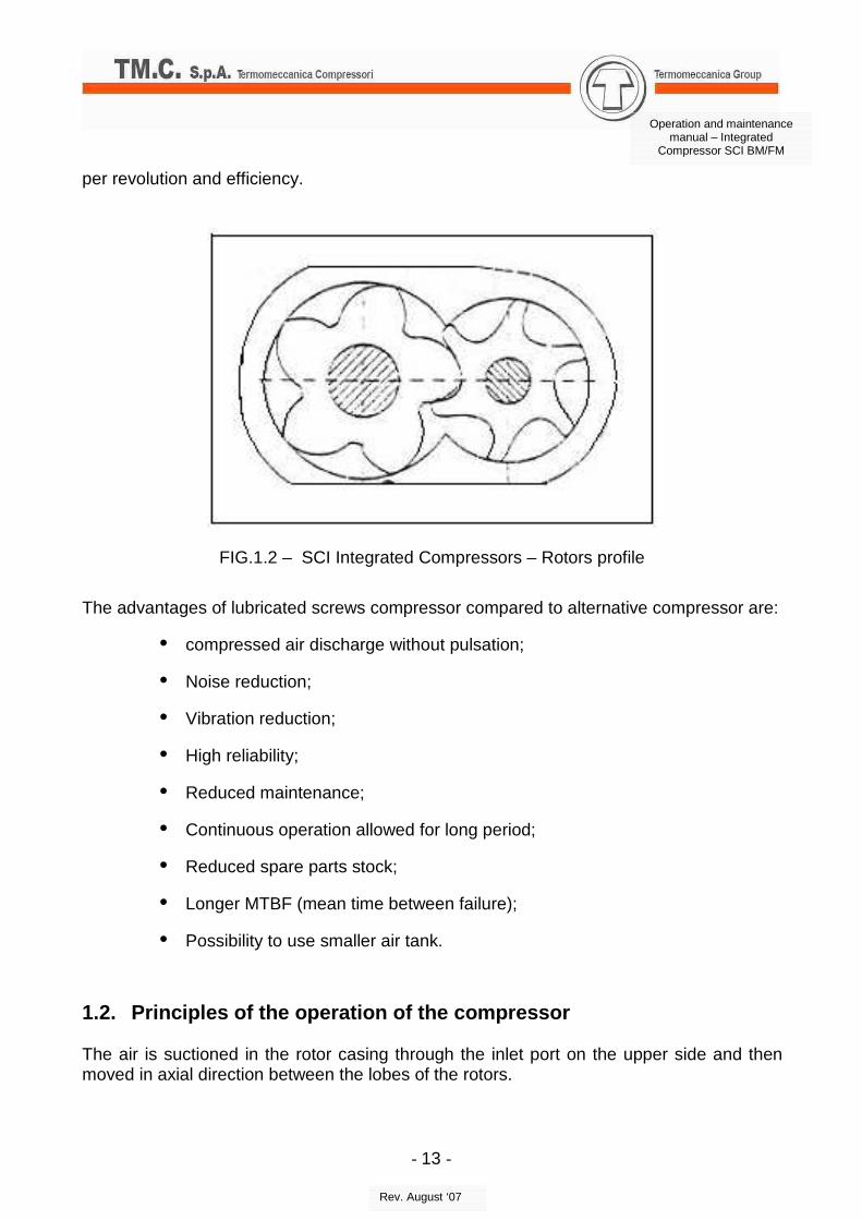
FIG.1.1 – Integrated Compressors SCI – a) SCI7, b) SCI8 The profile is the S.R.M. asymmetric, with 5 lobes on the male rotor and 6 lobes on the female rotor. This solution can guarantee the optimal result regarding stiffness, air volume
The advantages of lubricated screws compressor compared to alternative compressor are:
• compressed air discharge without pulsation;
• Noise reduction;
• Vibration reduction;
• High reliability;
• Reduced maintenance;
• Continuous operation allowed for long period;
• Reduced spare parts stock;
• Longer MTBF (mean time between failure);
• Possibility to use smaller air tank.
1.2. Principles of the operation of the compressor The air is suctioned in the rotor casing through the inlet port on the upper side and then moved in axial direction between the lobes of the rotors.
- 14 -
Operation and maintenance manual – Integrated
Compressor SCI BM/FM
Rev. August ‘07
Due to the rotation, the spaces between the lobes become larger, in the upper side of the rotors, till the maximum opening for the entire length. In this way it is possible to intake the air.
As the rotation continues, the space between the lobes, now full of air, becomes smaller and after a first phase of simple axial delivery, the compression starts in the lower part of the machine.
The compression phase is made by the meshing of the lobes of the male rotor in the spaces of the female rotor.
The “V” chambers, formed by the closing of the spaces between the rotors, due to the rotation, are constantly reducing their volume towards the discharge.
The air closed in each chamber is consequently compressed, during the axial movement , until the outlet port, where it is discharged.
The described process is repeated the same number of time as the number of lobes of the male rotor.
During the operation, inside the SCI compressors it is necessary to inject a big quantity of oil, to lubricate the mechanical parts (rotors, bearings, seal), to guarantee the seal between the rotors and between the rotor casing and the rotors, to dissipate the heat.
All the oil is discharged with the air from the outlet port, and has to be separated from it and then cooled to be used again.
The separated oil is collected in the lower part of the compressor tank and passing through the thermostatic valve it flows to an internal circuit or the external cooling circuit. In the first case the oil flows through the thermostatic valve, the oil filter and then injected to the rotors. In case the temperature raises over 70°C, the therm ostatic valve opens the external circuit to the cooler. Then the oil flows back to the compressor, through the oil filter and then is injected to the rotors. The discharge pressure must be high enough to guarantee the oil circulation (> 3 bar). The compressed air, with residual oil, is collected in the upper part of the tank of the SCI compressor casing, and then delivered to the oil separator filter. The oil residual, separated by the oil separator filter, are carried back to the suction area through internal channels. The clean air, in case of load running (solenoid valve energized and closed) is discharged through the minimum pressure valve. In case of idle condition (solenoid valve not energized and open), the clean air is discharged to atmosphere through the suction valve. A small quantity of the air is used to close the suction valve and avoid further air is passing through.
- 15 -
Operation and maintenance manual – Integrated
Compressor SCI BM/FM
Rev. August ‘07
1.3. Unit \ Apparatus of the compressor In this paragraph the main parts composing the SCI compressor and others necessary to package it are listed. 1.3.1 Unit \ Apparatus internal to the compressor In the SCI Integrated Compressors casings are present the seats for all main components necessary to operate and regulate the compressor. Internally are also present all the channels necessary to recover the oil separated in the oil separator filter, to switch the compressor to idle condition and discharge the air, to rubricate the machine, a part from the cooler. The most relevant components of the SCI compressor are listed here:
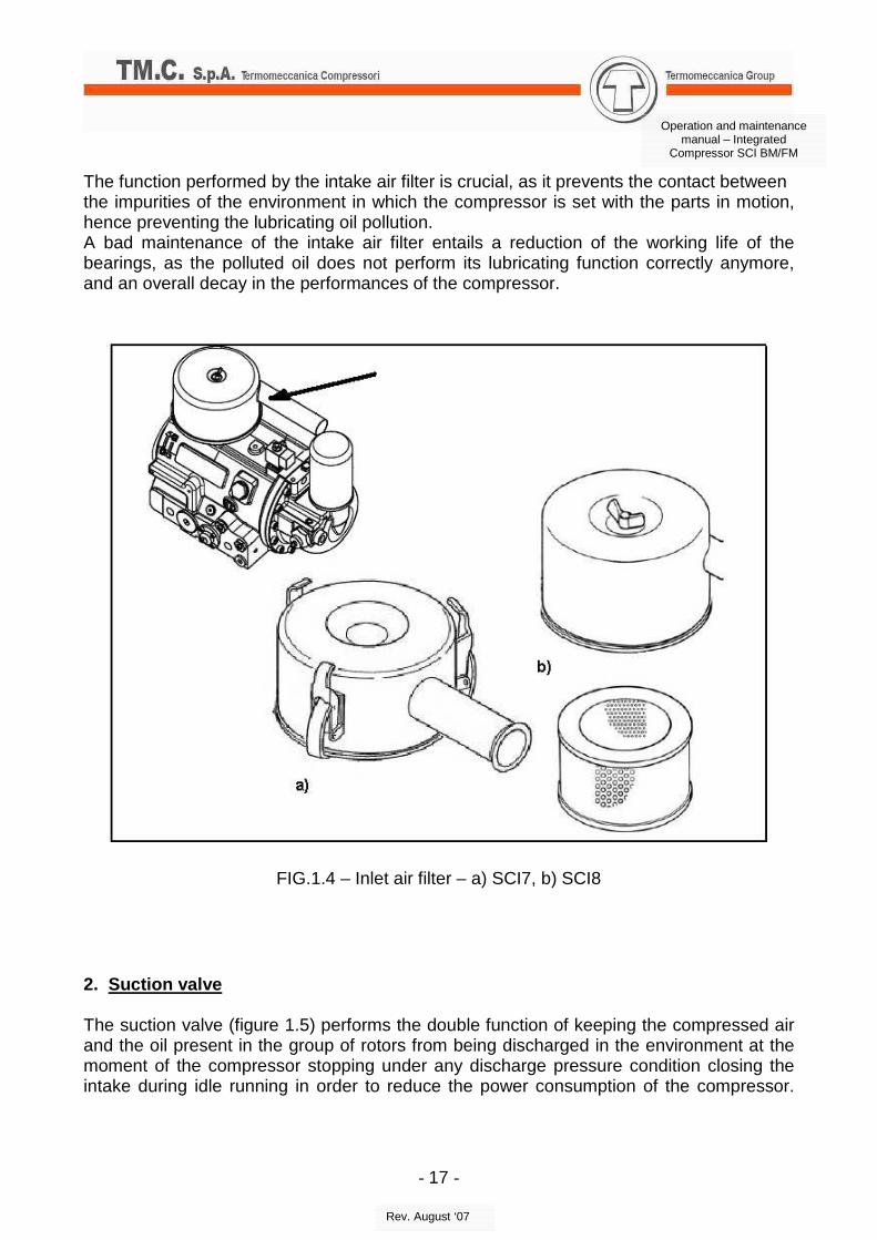
1. Air Filter The air filter (figure 1.4) consists of a container in painted metal specifically designed to reduce the noise generated by the air intake and by the paper cartridge having a filtration grading of 0.010 mm.
- 17 -
Operation and maintenance manual – Integrated
Compressor SCI BM/FM
Rev. August ‘07
The function performed by the intake air filter is crucial, as it prevents the contact between the impurities of the environment in which the compressor is set with the parts in motion, hence preventing the lubricating oil pollution. A bad maintenance of the intake air filter entails a reduction of the working life of the bearings, as the polluted oil does not perform its lubricating function correctly anymore, and an overall decay in the performances of the compressor.
FIG.1.4 – Inlet air filter – a) SCI7, b) SCI8
2. Suction valve The suction valve (figure 1.5) performs the double function of keeping the compressed air and the oil present in the group of rotors from being discharged in the environment at the moment of the compressor stopping under any discharge pressure condition closing the intake during idle running in order to reduce the power consumption of the compressor.
- 18 -
Operation and maintenance manual – Integrated
Compressor SCI BM/FM
Rev. August ‘07
According to operation condition it is necessary to ad just idle pressure, by the use of the appropriate screw, already adjusted by TM.C..
FIG.1.5 – Suction valve – a) SCI7, b) SCI8
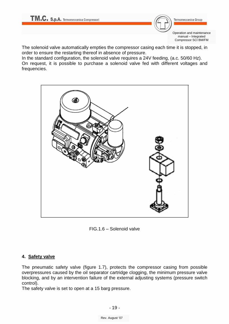
3. Solenoid valve The solenoid valve (figure 1.6), normally open, is controlled with a pressure switch (not included in the compressor) that keeps it closed during the loaded running phase. Once the required pressure has been reached, the solenoid valve opens, discharging all the suctioned air by the compressor inside the intake filter.
- 19 -
Operation and maintenance manual – Integrated
Compressor SCI BM/FM
Rev. August ‘07
The solenoid valve automatically empties the compressor casing each time it is stopped, in order to ensure the restarting thereof in absence of pressure. In the standard configuration, the solenoid valve requires a 24V feeding, (a.c. 50/60 Hz). On request, it is possible to purchase a solenoid valve fed with different voltages and frequencies.
FIG.1.6 – Solenoid valve
4. Safety valve The pneumatic safety valve (figure 1.7), protects the compressor casing from possible overpressures caused by the oil separator cartridge clogging, the minimum pressure valve blocking, and by an intervention failure of the external adjusting systems (pressure switch control). The safety valve is set to open at a 15 barg pressure.
- 20 -
Operation and maintenance manual – Integrated
Compressor SCI BM/FM
Rev. August ‘07
FIG.1.7 – Safety valve
5. Oil separator filter The oil coalescence separator cartridge (figure 1.8) completes the operation of separating the oil from the compressed air which started inside the casing by means of a flapping labyrinth and a successive speed change. The filter is of the spin-on cartridge kind, easy to replace, ensuring a percentage of oil in air lower than 5 ppm (at 80°C temperature). A good functioning of the oil separator depends on the operative temperature of the compressor, on the quality of the oil and on the general maintenance of the machine. It is possible to check the clogging of the oil separator, by the use of the pressure ports (G 1/8”) upstream and downstream the separator. It is recommended to substitute the cartridge as the differential pressure exceeds 0,5 bar.
- 21 -
Operation and maintenance manual – Integrated
Compressor SCI BM/FM
Rev. August ‘07
FIG.1.8 – Oil separator filter
FIG.1.9 – Oil drainage sight glass
- 22 -
Operation and maintenance manual – Integrated
Compressor SCI BM/FM
Rev. August ‘07
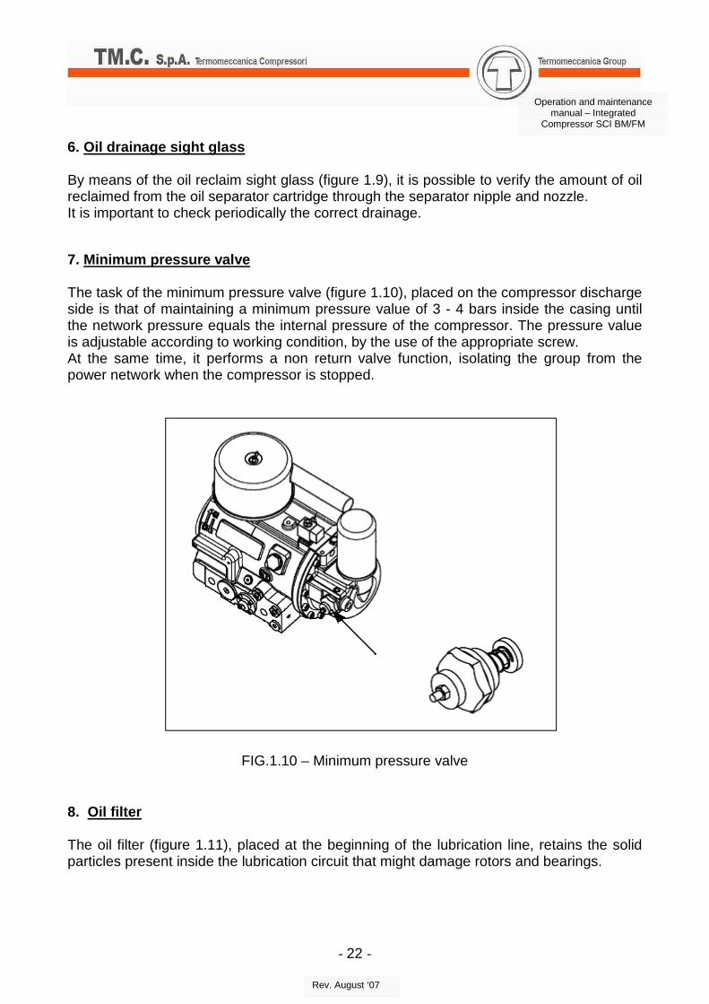
6. Oil drainage sight glass By means of the oil reclaim sight glass (figure 1.9), it is possible to verify the amount of oil reclaimed from the oil separator cartridge through the separator nipple and nozzle. It is important to check periodically the correct drainage. 7. Minimum pressure valve The task of the minimum pressure valve (figure 1.10), placed on the compressor discharge side is that of maintaining a minimum pressure value of 3 - 4 bars inside the casing until the network pressure equals the internal pressure of the compressor. The pressure value is adjustable according to working condition, by the use of the appropriate screw. At the same time, it performs a non return valve function, isolating the group from the power network when the compressor is stopped.
FIG.1.10 – Minimum pressure valve
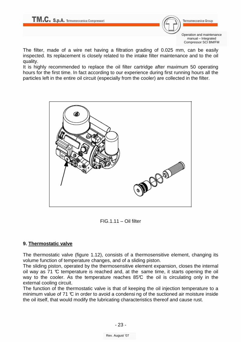
8. Oil filter The oil filter (figure 1.11), placed at the beginning of the lubrication line, retains the solid particles present inside the lubrication circuit that might damage rotors and bearings.
- 23 -
Operation and maintenance manual – Integrated
Compressor SCI BM/FM
Rev. August ‘07
The filter, made of a wire net having a filtration grading of 0.025 mm, can be easily inspected. Its replacement is closely related to the intake filter maintenance and to the oil quality. It is highly recommended to replace the oil filter cartridge after maximum 50 operating hours for the first time. In fact according to our experience during first running hours all the particles left in the entire oil circuit (especially from the cooler) are collected in the filter.
FIG.1.11 – Oil filter
9. Thermostatic valve The thermostatic valve (figure 1.12), consists of a thermosensitive element, changing its volume function of temperature changes, and of a sliding piston. The sliding piston, operated by the thermosensitive element expansion, closes the internal oil way as 71 °C temperature is reached and, at the same time, it starts opening the oil way to the cooler. As the temperature reaches 85°C the oil is circulating only in the external cooling circuit. The function of the thermostatic valve is that of keeping the oil injection temperature to a minimum value of 71 °C in order to avoid a condensi ng of the suctioned air moisture inside the oil itself, that would modify the lubricating characteristics thereof and cause rust.
- 24 -
Operation and maintenance manual – Integrated
Compressor SCI BM/FM
Rev. August ‘07
FIG.1.12 – Thermostatic valve
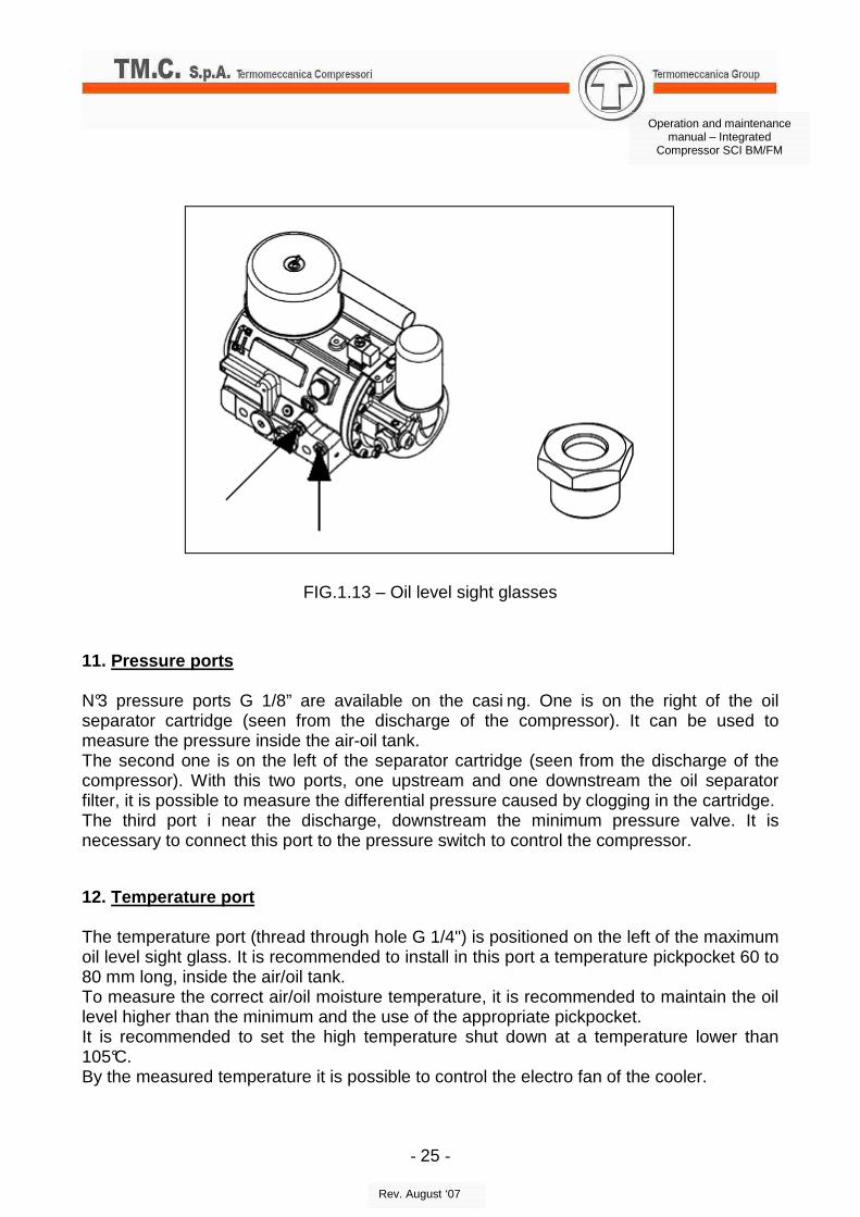
10. Oil level sight glasses The minimum oil level can be checked by means of the oil level sight glass provided for the purpose (figure 1.13), placed on the right of the thermostatic valve. The oil level must not sink below the lower half of the oil level sight glass when the compressor is not running. The maximum oil level can be checked by means of the oil level sight glass provided for the purpose placed above the thermostatic valve. The oil level must not exceed a half of the oil level sight glass.
- 25 -
Operation and maintenance manual – Integrated
Compressor SCI BM/FM
Rev. August ‘07
FIG.1.13 – Oil level sight glasses
11. Pressure ports N°3 pressure ports G 1/8” are available on the casi ng. One is on the right of the oil separator cartridge (seen from the discharge of the compressor). It can be used to measure the pressure inside the air-oil tank. The second one is on the left of the separator cartridge (seen from the discharge of the compressor). With this two ports, one upstream and one downstream the oil separator filter, it is possible to measure the differential pressure caused by clogging in the cartridge. The third port i near the discharge, downstream the minimum pressure valve. It is necessary to connect this port to the pressure switch to control the compressor.
12. Temperature port The temperature port (thread through hole G 1/4") is positioned on the left of the maximum oil level sight glass. It is recommended to install in this port a temperature pickpocket 60 to 80 mm long, inside the air/oil tank. To measure the correct air/oil moisture temperature, it is recommended to maintain the oil level higher than the minimum and the use of the appropriate pickpocket. It is recommended to set the high temperature shut down at a temperature lower than 105°C. By the measured temperature it is possible to control the electro fan of the cooler.
- 26 -
Operation and maintenance manual – Integrated
Compressor SCI BM/FM
Rev. August ‘07
13. Oil unload The oil unload plug (figure 1.14), placed directly on the compressor casing, eases the oil change operations at the required maintenance intervals. Removing the plug the periodical operations of checking the presence of condensate in the oil can be carried out. All the operations must be carried out in absence of internal pressure.
FIG.1.14 – Oil unload
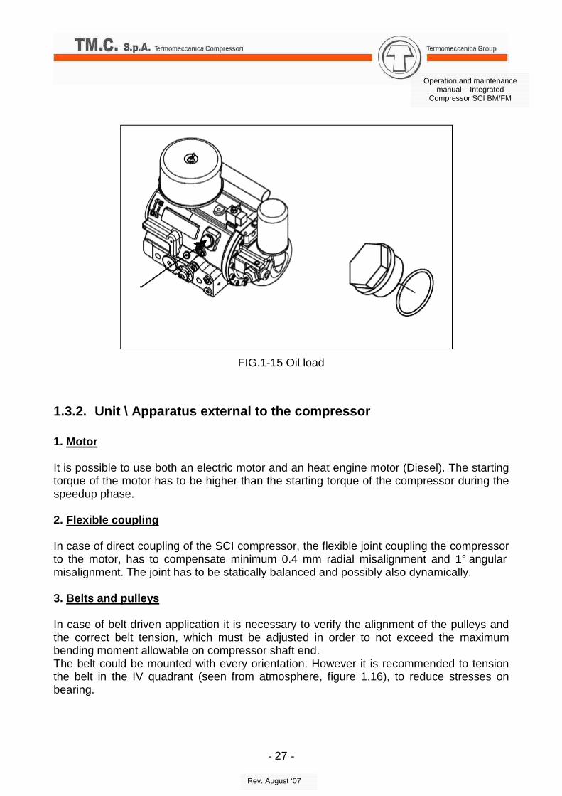
14. Oil load The oil load plug (figure 1.15), is placed directly on the compressor casing and is marked by a filler cap. The accessing to the filler cap must be carried out in only in absence of internal pressure. The maximum level of the oil can be checked by means of the oil level sight glass placed over the thermostatic valve. The maximum oil level must not exceed a half of the oil level sight glass horizontal length.
- 27 -
Operation and maintenance manual – Integrated
Compressor SCI BM/FM
Rev. August ‘07
FIG.1-15 Oil load
1.3.2. Unit \ Apparatus external to the compressor 1. Motor It is possible to use both an electric motor and an heat engine motor (Diesel). The starting torque of the motor has to be higher than the starting torque of the compressor during the speedup phase. 2. Flexible coupling In case of direct coupling of the SCI compressor, the flexible joint coupling the compressor to the motor, has to compensate minimum 0.4 mm radial misalignment and 1° angular misalignment. The joint has to be statically balanced and possibly also dynamically. 3. Belts and pulleys In case of belt driven application it is necessary to verify the alignment of the pulleys and the correct belt tension, which must be adjusted in order to not exceed the maximum bending moment allowable on compressor shaft end. The belt could be mounted with every orientation. However it is recommended to tension the belt in the IV quadrant (seen from atmosphere, figure 1.16), to reduce stresses on bearing.
- 28 -
Operation and maintenance manual – Integrated
Compressor SCI BM/FM
Rev. August ‘07
FIG.1.16 – Belt driven assembly lay-out 4. Connections (air oil, water) The piping used must be of the correct dimensions, to guarantee that the flow speed is lower than admissible. Reference values for flow speed are given here after:
� Inlet line (air) 15 – 20 m/s
� Discharge line (air with residual oil) 5 – 8 m/s
� Discharge line (air without residual oil) 20 – 25 m/s
� Oil line 0.5 – 2 m/s
� Water line 2 – 3 m/s
5. Air cooler and condensate drainage The air is discharged at a temperature of about 80 – 100 °C, than it could be necessary to cool it down.
- 29 -
Operation and maintenance manual – Integrated
Compressor SCI BM/FM
Rev. August ‘07
If an air cooler is used, the temperature could become lower than the dew point., so it is necessary to mount on the line a condensate drainage system, to separate the water from the air. 6. Electrical panel The electrical panel controls the entire compressor package. Correct setting must be carried out:
˘ High temperature emergency stop (105°C);
˘ Load/unload cycles timing according to ambient temperature and operation condition to avoid condensate inside the compressor;
˘ Hour counter and maintenance operation timer;
˘ Alarms: high temperature, high pressure, high power absorption, etc...
1.4. Assembly/operation of the compressor a) Assembly
SCI compressors are available in two different models:
� BM to be used base mounted, fixing it by n°4 M10 r eference holes (named A in
figure 1.17);
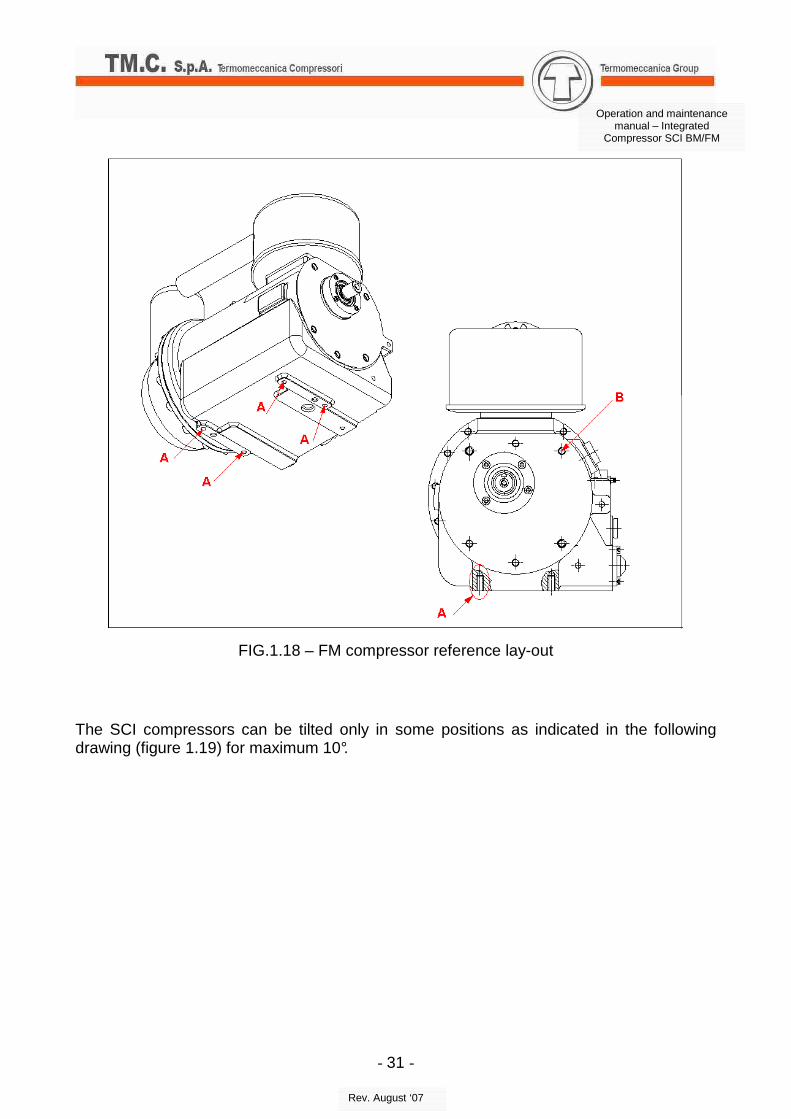
� FM to be used flange mounted, fixing it by n°6 M10 reference holes (named B in
figure 1.18); if necessary it is possible to mount it on the base too, by n°4 M10
reference holes (named A in figure 1.18)
It is possible to use the seal cover, machined in the external diameter with the g6 tolerance range, for the centering of a bell housing or connection adaptor to the motor.
- 30 -
Operation and maintenance manual – Integrated
Compressor SCI BM/FM
Rev. August ‘07
FIG.1.17 – BM compressor reference lay-out
- 31 -
Operation and maintenance manual – Integrated
Compressor SCI BM/FM
Rev. August ‘07
FIG.1.18 – FM compressor reference lay-out
The SCI compressors can be tilted only in some positions as indicated in the following drawing (figure 1.19) for maximum 10°.
The compressor must be electrically isolated from the other parts of the plant, through its dedicated ground cable. The lack of observance of this rule can cause the origin of galvanic current, through the compressor itself, that could seriously damage the machine. The lack of a ground cable in the compressor causes electrostatic charge storage inside it, during the operation, with the risk of explosion and fire in the machine. b) Operation
The operation of the SCI compressor is possible in two different solutions:
� With direct driving, both belt driven or direct driven configuration
� With internal Gear box (named with the suffix G)
SCI Compressor direct driving The male rotor is driven by belt or directly from the motor. The rotor requested rotation speed is achieved by the transmission ratio given by the selected pulleys in case of belt driven, whereas it is exactly the same of the motor in case of direct driven.
- 33 -
Operation and maintenance manual – Integrated
Compressor SCI BM/FM
Rev. August ‘07
SCI G Compressor
The male rotor is driven by a gear box, to ad just the motor speed to the requested rotation speed of the rotor. The coupling of the motor is to be realized by an appropriate flexible joint.
- 34 -
Operation and maintenance manual – Integrated
Compressor SCI BM/FM
Rev. August ‘07
2. FUNCTIONAL DESCRIPTION 2.1 Introduction
In this Section a functional description of the SCI series compressors is provided.
The description is divided into sections and is complete with figures identifying all the main components that concur to the functioning of the apparatus/unit.
Please refer to the Supplementary Technical Manual for technical data specific for each compressor model.
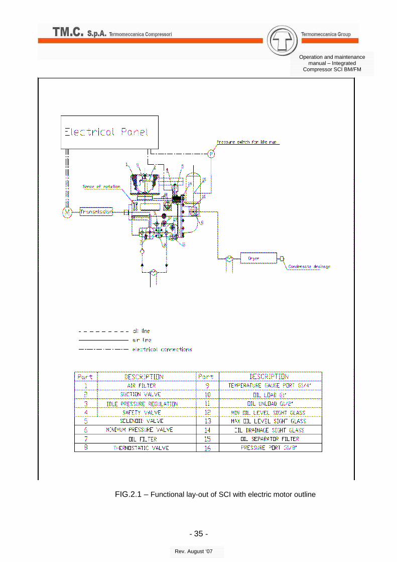
2.2. Functional description of SCI with electric motor This paragraph shows, with reference to the functional diagram in fig. 2.1, the SCI compressor coupled to an electric motor.
a. Motor start/star connection The suction valve (2) is closed, The discharge valve is open. The solenoid valve (5) is switched on idle running. The electric motor (M) is started with star connection. b. Motor star/delta switching Electric motor (M) is switched to delta connection. The solenoid valve (5) is switched to load running.. The discharge valve closes. Suction valve (2) opens. c. Load running The minimum pressure valve (6) does not open till a pressure of 3.5-4 barg is reached inside the tank. This pressure guarantees a sufficient lubrication of the compressor. The compressor conveys the air to the user circuit as soon as the pressure upstream the check valve (6) is higher than the pressure downstream. The minimum pressure valve service and the check valve service are obtained by a single valve.
- 35 -
Operation and maintenance manual – Integrated
Compressor SCI BM/FM
Rev. August ‘07
FIG.2.1 – Functional lay-out of SCI with electric motor outline
- 36 -
Operation and maintenance manual – Integrated
Compressor SCI BM/FM
Rev. August ‘07
d. Load running/idle running As soon as the pressure switch (P) reaches the maximum switching point, the solenoid valve (5) switches to idle running and the suction valve (2) closes. The compressor is unloaded at the idle pressure through the discharge valve, the check valve (6) closes and separates the compressor unit from the line. The idle pressure must be higher than 1.5 barg. As soon as the line air pressure reaches the minimum switching point of the switch (P), the solenoid valve (5) switches to load and the suction valve (2) opens, The minimum pressure valve (6) opens as described in the load running (point c).
e. Stop The compressor stop should occur according to the procedure described hereinafter:
e.1. The solenoid valve (5) switches to idle condition and the suction valve (2) closes
e.2. The discharge line opens and the unit is discharged to atmospheric pressure, while it is separated from the line by the check valve (6)
e.3. The motor (M) can be stopped f. Emergency stop Should the lack of power occur, or owing to the intervention of a safety device, the unit is disconnected. The check valve (6) closes to avoid a reflux of air and oil through the compressor, preventing its inverted running. The suction valve (2), which is working as check valve too, closes to avoid oil leakage from inlet.
- 37 -
Operation and maintenance manual – Integrated
Compressor SCI BM/FM
Rev. August ‘07
2.3. Functional description of SCI with heat engine moto r This paragraph shows, with reference to the functional diagram in fig. 2.2, the SCI compressor coupled to an heat engine motor.
a. Compressor start up
While the compressor is in stand by: The suction valve (2) is closed The discharge valve (6) is open. The solenoid valve (5) is switched to idle running At start-up: The motor (M) is stated at the minimum speed. discharge valve (10) is closed.
b. Load running The solenoid valve (5) is switched to load condition; the motor (M) runs at maximum speed and the suction valve (2) opens. The minimum pressure valve (6) does not open till the compressor unit reaches the 3.5-4 barg. The compressor conveys the air to the user circuit as soon as the pressure upstream the check valve (6) is higher than the pressure downstream. The minimum pressure valve service and the check valve service are obtained by a single valve.
c. Load running/idle running As soon as the pressure switch (P) reaches the maximum switching point, the solenoid valve (5) switches to idle running and the suction valve (2) closes. The motor (M) runs at minimum speed. As soon as the line air pressure reaches the minimum switching point of the switch (P), the solenoid valve (5) switches to load and the suction valve (2) opens. The motor (M) runs at maximum speed. The minimum pressure valve (6) opens as described in the load running (point b).
- 38 -
Operation and maintenance manual – Integrated
Compressor SCI BM/FM
Rev. August ‘07
d. Stop
d.1. The compressor is discharged at atmospheric pressure and separated from the line by the check valve (6).
d.2. At the same time the solenoid valve (5) opens and the suction valve (2) closes. The motor (M) runs at minimum speed.
d.3. Subsequently the motor (M) can be stopped e. Emergency stop Should the lack of power occur, or owing to the intervention of a safety device, the unit is disconnected. The check valve (6) closes to avoid a reflux of air and oil through the compressor, preventing its inverted running. The suction valve (2), which is working as check valve too, closes to avoid oil leakage from inlet.
- 39 -
Operation and maintenance manual – Integrated
Compressor SCI BM/FM
Rev. August ‘07
FIG.2.2 – Functional lay-out of SCI with heat engine motor outline
- 40 -
Operation and maintenance manual – Integrated
Compressor SCI BM/FM
Rev. August ‘07
3. SAFETY RULES 3.1 Introduction In this section general safety rules for the use of a compressor SCI are provided.
Particular safeguard, referred to specific operation for assembly, maintenance and check, are specified in the MTI.
NOTE
The lack of observance of the safety rules can cause serious injuries to the personnel working and/or to everyone in proximity.
3.2 Precaution for installation and standard operat ion Position the compressor in a clean and cool air ambient.
If it is necessary to position the compressor in a dusty and/or hot ambient, must design a suction line to convey clean and cool air.
The suctioned air must be free of inflammable gas and vapour, to eliminate any risk of fire and explosion inside the compressor. To prevent the temperature increase in the convey system, check and clean periodically the heat exchange surfaces Assure that the discharge line of the compressor, to the distribution line, is free to expand, if an high temperature increase occurs, and it is not in contact with inflammable materials. Preserve the compressor clean and remove dust and oil deposits as much as possible. Design the lay-out of inlet line, in order to avoid any possible danger: contact with prominent parts, entrapment of clothes or hair.
NOTE The compressor must be electrically isolated from the other parts of the plant, through its dedicated ground cable. The lack of observance of this rule can cause the origin of galvanic current, through the compressor itself, that could seriously damage the machine. The lack of a ground cable in the compressor causes electrostatic charge storage inside it, during the operation, with the risk of explosion and fire in the machine.
3.3 Use of an air blow The use of an air blow, that must be always lower than 8 bar, to dry parts after cleaning with solvent, causes the dispersion in the ambient of dust particles or solvent drops; this can cause irritation to skin, eyes or breathing apparatus.
While using an air blow, never direct it to the skin or another person.
Do not use the air blow to clean clothes.
- 41 -
Operation and maintenance manual – Integrated
Compressor SCI BM/FM
Rev. August ‘07
Improper use of an air blow can cause injuries or death.
While using an air blow, it is necessary to wear a safeplate. 3.4 Use of solvent The use of solvent or chemical agents can affect health and safety.
Manufacturers of those kind of products should be contacted to obtain information on safeguard and their precautions should be followed.
Never use inflammable liquids to clean valves, filters, tank connections, inlet and outlet piping, air tank or any other component exposed to the airflow during the operation. 3.5 Electric components The use of electric material must comply with the main characteristics indicated by the manufacturer, to avoid any dangerous situation.
Components must be used to avoid temperature excess, electric arc, radiations.
To prevent electric shock during tests, do not touch electric components, connections and bin and the operative staff do not touch the test bench.
NOTE
The lack of observance of the safety rules can cause serious injuries or death.
3.6 Intervention safeguard Before executing any intervention on the compressor, check that the compressor is disconnected from the motor.
Air delivery or electric current to the unit and/or any components must be shut before the removal of the unit and/or any components from their seat.
After disconnecting the motor, check that the air inside the compressor has been discharged, before proceeding to any intervention on it.
Follow the instructions to avoid starting unsought, sudden or out of control.
Disassemble with care, to avoid any components to cause injuries.
Assemble with care, positioning carefully all the components, even the small ones, to avoid accidental disassembly during the compressor operation.
Be careful to not touch hot parts of the compressor: rotor casing, discharge casing, minimum pressure valve, oil separator filter.
- 42 -
Operation and maintenance manual – Integrated
Compressor SCI BM/FM
Rev. August ‘07
3.7 Handling safeguard A lift with the adequate capacity should be available during the execution of the removal, installation and maintenance operations. The SCI compressors are heavy(56kg SCI7; 57kg SCI8); take care during each operation.
While handling, take care particularly to the prominent parts (male shaft end, oil separator filter, air filter), because the contact could cause serious injuries to the personnel and/or people in proximity.
3.8 Testing safeguard While executing any test on an equipment or components, if it is mounted on the plant (during a plant test, etc.) check it is not possible to start the compressor accidentally, to avoid injuries to the personnel or damages to the parts.
- 43 -
Operation and maintenance manual – Integrated
Compressor SCI BM/FM
Rev. August ‘07
4. OPERATION PROCEDURES 4.1. Air flow adjustment on a SCI compressor
The SCI compressor can be equipped with an air flow adjustment control system of these types:
���� Full load – idle running
���� Full load – stop
It is possible to install both control types to be used alternate.
If the air delivery must be reduced or stopped for a short period, it is recommended to use a control full load – idle running.
If the air delivery must be stopped for a long period, or if small air quantity is required, it is recommended to use a control full load – stop, to avoid an extended idle running of the unit. In this case it is important that the motor will not start more than 3 – 4 times per hour.
4.2. Pressure adjustment on a SCI compressor Discharge pressure is adjusted by the use of a pressure switch on discharge line.
4.3. Operation procedures with limited functionalit y Due to different reasons the SCI compressor and/or units/apparatus part of the compressor or controlling its functions could fail. In this case, assuming that the compressor will stop for lack of power or the intervention of a safety system ( see Par.2.2 point f.), it is possible, due to operative reasons, to continue operation in the following cases:
4.4.a Oil leakage.
In this case check constantly the oil level and if it gets down under the minimum level, STOP IMMEDIATELY THE COMPRESSOR.
4.3.b Anomalous motor power absorption
If the power absorption is remaining 5 – 10 % higher than nominal, it is possible to continue operation. If the power absorption exceeds 10 % higher than nominal STOP IMMEDIATELY THE COMPRESSOR.
- 44 -
Operation and maintenance manual – Integrated
Compressor SCI BM/FM
Rev. August ‘07
3.4.c Low air flow
If the actual air flow is lower than the nominal value of 5 to 20 %, and there are no other fail as noise, high power absorption, etc, it is possible to continue operation. If the air flow decreases under -20 % lower than nominal STOP IMMEDIATELY THE COMPRESSOR
Follow safety rules while operating on equipments and/or components of SCI compressor system.
Never exceed recommended pressure, speed, bending moment 4.4. Operation procedures in case of failure
In case of failure, execute the following intervention steps:
1. Obtain as much information as possible. Try to look for information essential to understand what happened and in which conditions, and if the problem is “local” or from the plant (affecting different units).
2. The first step before looking for the failure is to repeat it, if possible, and LEAVE THE SYSTEM IN FAIL STATUS
This course of action allows the following:
2.1. to verify the origin of the problem and to record the information in the failure report.
2.2. to start with targeted intervention to avoid any random trails to fix the failure.
3. As the failure has be repeated, it is important to avoid the use of the equipments in this status, until full working condition is not achieved. The problem at first sight could seems to be temporarily solved but it is possible to find it again.
4. Next step is to identify the problem and its reason. Proceed carefully, leaving the plant in failure condition, and localize the problem by the failure search instructions. It depends on the plant system and personal preference to isolate the plant. The best way to proceed is to isolated monitoring, to avoid random trials. If the problem is a breakage it is easy to isolate the broken component. But most of the reasons for failure are not so evident. Every time a component is removed, substituted or repaired, it is necessary to perform a functional operative test of the system, to be sure the component is working correctly.
5. While the system is in failure it is recommended to refer to the information in the manuals, to learn about how the system works, before to modify the failure status. It is important to consider that the system is in failure condition and it is not working correctly.
- 45 -
Operation and maintenance manual – Integrated
Compressor SCI BM/FM
Rev. August ‘07
6. Sometimes just intervening in a random way on the system in failure, could seem to solve the problem, it is recommended to verify the identified component, under suspicion, is really the cause of the failure, by installing it again on the system, to verify the failure condition is still present. The procedure is the following:
6.1 As a component is identified to be in fail, substitute it with a new one, to verify the correct working.
6.2 Install again the component not working and verify the failure condition is present again.
6.3 If the check confirms the not working component, conclusively substitute it and check again the system, to verify all the other isolated parts are restored to standard working position.
7. As the work is completed, it is recommended to record all information useful for the solution of the failure (description of the failure, intervention performed, description of the failed component, etc.), to collect a document to refer to in case of a future similar failure.
4.5. Cleaning and storage
It is important that the compressor be kept free of dirt, to reduce risks of malfunctioning.
The cleaning of the outer parts must be performed with water, but special attention should be paid to the use of cleaning devices employing high pressure or steam, especially in the housings of the electrical components (motor).
To remove grease use Varsol or similar.
After the cleaning operations the compressor needs to be dried.
If the compressor should be kept stored it is necessary to periodically fill with oil (0,2-0,5 dm3 from inlet) and rotate the shaft.
The compressor should be stored in a dry room and it is necessary to apply protective matter on external surfaces after the first three months.
- 46 -
Operation and maintenance manual – Integrated
Compressor SCI BM/FM
Rev. August ‘07
5. PREVENTIVE MAINTENANCE 5.1. Introduction The purpose of this section is to provide to the maintenance staff procedures and data that are required for a correct and swift execution of the maintenance operations for SCI compressors. The scheduled maintenance operations for the SCI Compressor correspond to the carrying out of the following test:
a. Maintenance procedures
b. Performance checks
The scheduled maintenance procedures are reported as cards, and all the information pertaining to each card are summarized in the maintenance procedures.
The section is divided as follows:
a. Maintenance Card Index
b. Maintenance Procedures
c. Performance check
Explanations regarding the use of the maintenance procedure index and of the maintenance cards are provided here below.
5.1.1. Use of the maintenance procedure index
The maintenance procedure index reported in table 4-1 of each Supplementary Technical Manuals (MTI) provides the index and the cross references of all the maintenance procedures, listed according to their periodicity. This index is the basic document on which the maintenance program is realized and the tasks are assigned to the staff in charge.
The information provided by the maintenance procedure index are::
a. The configuration of the apparatus to which the document refers;
b. The list of the reference publications where further information on the maintenance of the apparatus at issue can be found;
c. A list of all the maintenance operations according to their periodicity, in a decreasing order;
d. The maintenance periodicity code;
e. The level of the staff in charge of the maintenance;
f. The man hours needed to carry out the procedure.
- 47 -
Operation and maintenance manual – Integrated
Compressor SCI BM/FM
Rev. August ‘07
5.1.2. Use of the scheduled maintenance cards
The scheduled maintenance cards reported in table 4-2 (available in each Supplementary Technical Manuals) provide all the technical information required to perform the maintenance procedure of interest.
Every scheduled maintenance card is divided into the following blocks:
a. SYSTEM
The system to which the subsystem object of the maintenance belongs is
indicated.
b. SUBSYSTEM
The Subsystem object of the maintenance is indicated.
c. UNIT
The Unit object of the maintenance is indicated.
d. PERIODICITY CODE
The abbreviations of the adopted periodicities are the following:
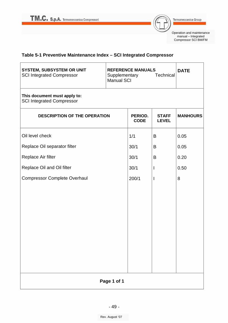
1/1 = corresponding to about 100 hrs of running
30/1 = corresponding to about 3000 hrs of running
200/1 = corresponding to about 20.000 hrs of running and to about 7 years.
e. STAFF LEVEL
The competence level or the professional aptitude of the Staff in charge of maintenance, is indicated with the following abbreviations:
B = Basic
I = Intermediate
f. MANHOURS
The time expressed in man hours (hours and tenths of hours) needed to carry out the maintenance is indicated.
g. TOTAL MANHOURS
The total time needed to perform the maintenance is indicated.
h. ENGAGEMENT OF APPARATUS
The time, expressed in hours and tenths of hours, during which the apparatus is engaged for the maintenance is indicated.
i. DESCRIPTION
The title assigned to the maintenance is indicated.
- 48 -
Operation and maintenance manual – Integrated
Compressor SCI BM/FM
Rev. August ‘07
l. SAFETY PRECAUTIONS
Precautions for the safety of the staff in charge of the apparatus maintenance are indicated.
m. TOOLS AND CONSUMABLES
All the tools, materials and measures needed to perform the maintenance procedure are listed.
n. PROCEDURE
The procedure for the maintenance execution is described, and the precautions needed to prevent harm to the staff or material damages are recalled case wise.
- 49 -
Operation and maintenance manual – Integrated
Compressor SCI BM/FM
Rev. August ‘07
Table 5-1 Preventive Maintenance Index – SCI Integr ated Compressor SYSTEM, SUBSYSTEM OR UNIT SCI Integrated Compressor
This document must apply to: SCI Integrated Compressor
DESCRIPTION OF THE OPERATION
PERIOD. CODE
STAFF LEVEL
MANHOURS
Oil level check Replace Oil separator filter Replace Air filter Replace Oil and Oil filter Compressor Complete Overhaul
1/1 30/1 30/1 30/1 200/1
B B B I I
0.05 0.05 0.20 0.50 8
Page 1 of 1
- 50 -
Operation and maintenance manual – Integrated
Compressor SCI BM/FM
Rev. August ‘07
5.1.3. Post - overhaul setting at work of the Compr essor
This section contains the operative directions concerning how to manage the various functions and adjustments, after the disassembly and the complete overhaul of the SCI Compressor.
a. Compressor repositioning
Insert the corresponding joint or pulley on the compressor shaft end.
Position the compressor on the base after the insertion, when needed, of the joint spacer, and lock it with the fixing screws
In case of belt driven application:
• Insert the belt;
• Ad just the compressor position to align the pulley on the compressor shaft end and the pulley on the motor shaft;
• Tension the belt following the instructions given by the belt manufacturer, considering that the radial force on the compressor shaft end must never exceed the maximum bending moment (allowable on the protrusion of the male rotor in correspondence of the pulley beating surface section), indicated in each specific MTI.
In case of direct driven application:
align the compressor and the motor so that the transversal, longitudinal and angular shaft misalignments do not exceed the maximum ones that can be compensated by the coupling, according to the instructions of the manufacturer.
b. Filling with oil of the compressor
Before first start up it is necessary to fill the compressor with 3.5 dm3 of suitable mineral or synthetic oil. 0.5 dm3 of oil must be filled directly from the inlet port of the compressor.
This operation must be repeated before starting, every time maintenance operations are performed.
Refers to paragraph 7.3 of this manual to define the recommended oils.
- 51 -
Operation and maintenance manual – Integrated
Compressor SCI BM/FM
Rev. August ‘07
c. Connection check
Make sure that all the connections with the apparatus and the compressor have been completed.
d. Direction of rotation check
Make sure that the driving rotor is operated in the direction of rotation indicated by the arrow highlighted on the compressor casing.
e. Electric isolation check
The compressor must be electrically isolated from the other parts of the plant, through its dedicated ground cable. The lack of observance of this rule can cause the origin of galvanic current, through the compressor itself, that could seriously damage the machine. The lack of a ground cable in the compressor causes electrostatic charge storage inside it, during the operation, with the risk of explosion and fire in the machine.
f. Compressor starting
After having performed the operations described in the preceding points a.-d., the starting can be performed, with the following steps:
f.1 Start the motor
f.2 Wait for the discharge pressure to reach the preset operative value
f.3 Make sure that anomalous vibration, noise values etc are not detectable
- 52 -
Operation and maintenance manual – Integrated
Compressor SCI BM/FM
Rev. August ‘07
6. Failure search 6.1. Introduction This section contains directions and information required to locate failures or discharge anomalies on the SCI Compressor. A failure logical table is provided as an aid for the failure search. This logical scheme is based on the failure indications observed in the process of failure search. The table includes the symptoms and the probable causes related to the failure isolation Each cause implies a specific cure, thereby gradually reducing the uncertainty field. Therefore, the functional area of the set wherein the failure is located will gradually be reduced, and lastly the information needed to complete the isolation and to perform the repair will be provided. Table 6-1 indicates the inconvenient and the cures that can be applied to eliminate the inconvenient found. In particular, for each failure found the corresponding corrective actions are listed to locate the damaged subsystems and/or components and restore the normal operative conditions..
NOTE
In the realization of the logical failure schemes, the assumption was made that the
incoming feeds and signals be present and that the harness be in order. The technical staff in charge of the failure search will have to make sure of the aforesaid
If, after having performed the indicated operations, the failure persists, contact the
TM.C. TERMOMECCANICA COMPRESSORI S.p.A. service center.
- 53 -
Operation and maintenance manual – Integrated
Compressor SCI BM/FM
Rev. August ‘07
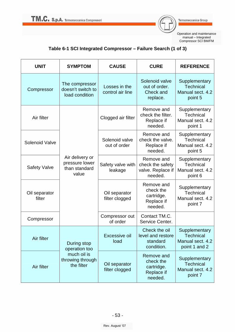
Table 6-1 SCI Integrated Compressor – Failure Searc h (1 of 3)
UNIT SYMPTOM CAUSE CURE REFERENCE
Compressor The compressor doesn’t switch to
load condition
Losses in the control air line
Solenoid valve out of order. Check and
replace.
Supplementary Technical
Manual sect. 4.2 point 5
Air filter Clogged air filter
Remove and check the filter.
Replace if needed.
Supplementary Technical
Manual sect. 4.2 point 1
Solenoid Valve Solenoid valve
out of order
Remove and check the valve.
Replace if needed.
Supplementary Technical
Manual sect. 4.2 point 5
Safety Valve Safety valve with
leakage
Remove and check the safety valve. Replace if
needed.
Supplementary Technical
Manual sect. 4.2 point 6
Oil separator filter
Oil separator filter clogged
Remove and check the cartridge. Replace if needed.
Supplementary Technical
Manual sect. 4.2 point 7
Compressor
Air delivery or pressure lower than standard
value
Compressor out of order
Contact TM.C. Service Center.
Air filter Excessive oil
load
Check the oil level and restore
standard condition.
Supplementary Technical
Manual sect. 4.2 point 1 and 2
Air filter
During stop operation too
much oil is throwing through
the filter Oil separator filter clogged
Remove and check the cartridge. Replace if needed.
Supplementary Technical
Manual sect. 4.2 point 7
- 54 -
Operation and maintenance manual – Integrated
Compressor SCI BM/FM
Rev. August ‘07
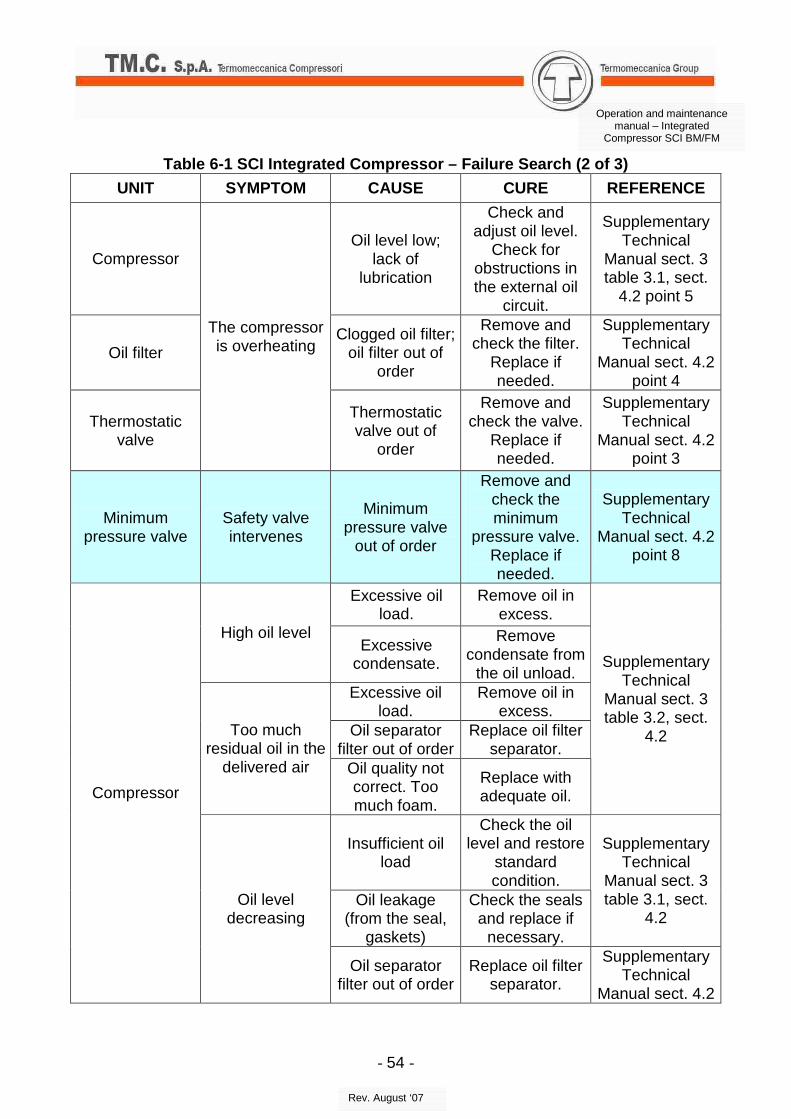
Table 6-1 SCI Integrated Compressor – Failure Searc h (2 of 3)
UNIT SYMPTOM CAUSE CURE REFERENCE
Compressor Oil level low;
lack of lubrication
Check and adjust oil level.
Check for obstructions in the external oil
circuit.
Supplementary Technical
Manual sect. 3 table 3.1, sect.
4.2 point 5
Oil filter Clogged oil filter;
oil filter out of order
Remove and check the filter.
Replace if needed.
Supplementary Technical
Manual sect. 4.2 point 4
Thermostatic valve
The compressor is overheating
Thermostatic valve out of
order
Remove and check the valve.
Replace if needed.
Supplementary Technical
Manual sect. 4.2 point 3
Minimum pressure valve
Safety valve intervenes
Minimum pressure valve
out of order
Remove and check the minimum
pressure valve. Replace if needed.
Supplementary Technical
Manual sect. 4.2 point 8
Excessive oil load.
Remove oil in excess.
High oil level Excessive
condensate.
Remove condensate from
the oil unload. Excessive oil
load. Remove oil in
excess. Oil separator
filter out of order Replace oil filter
separator. Too much
residual oil in the delivered air Oil quality not
correct. Too much foam.
Replace with adequate oil.
Supplementary Technical
Manual sect. 3 table 3.2, sect.
4.2
Insufficient oil load
Check the oil level and restore
standard condition.
Oil leakage (from the seal,
gaskets)
Check the seals and replace if
necessary.
Supplementary Technical
Manual sect. 3 table 3.1, sect.
4.2
Compressor
Oil level decreasing
Oil separator filter out of order
Replace oil filter separator.
Supplementary Technical
Manual sect. 4.2
- 55 -
Operation and maintenance manual – Integrated
Compressor SCI BM/FM
Rev. August ‘07
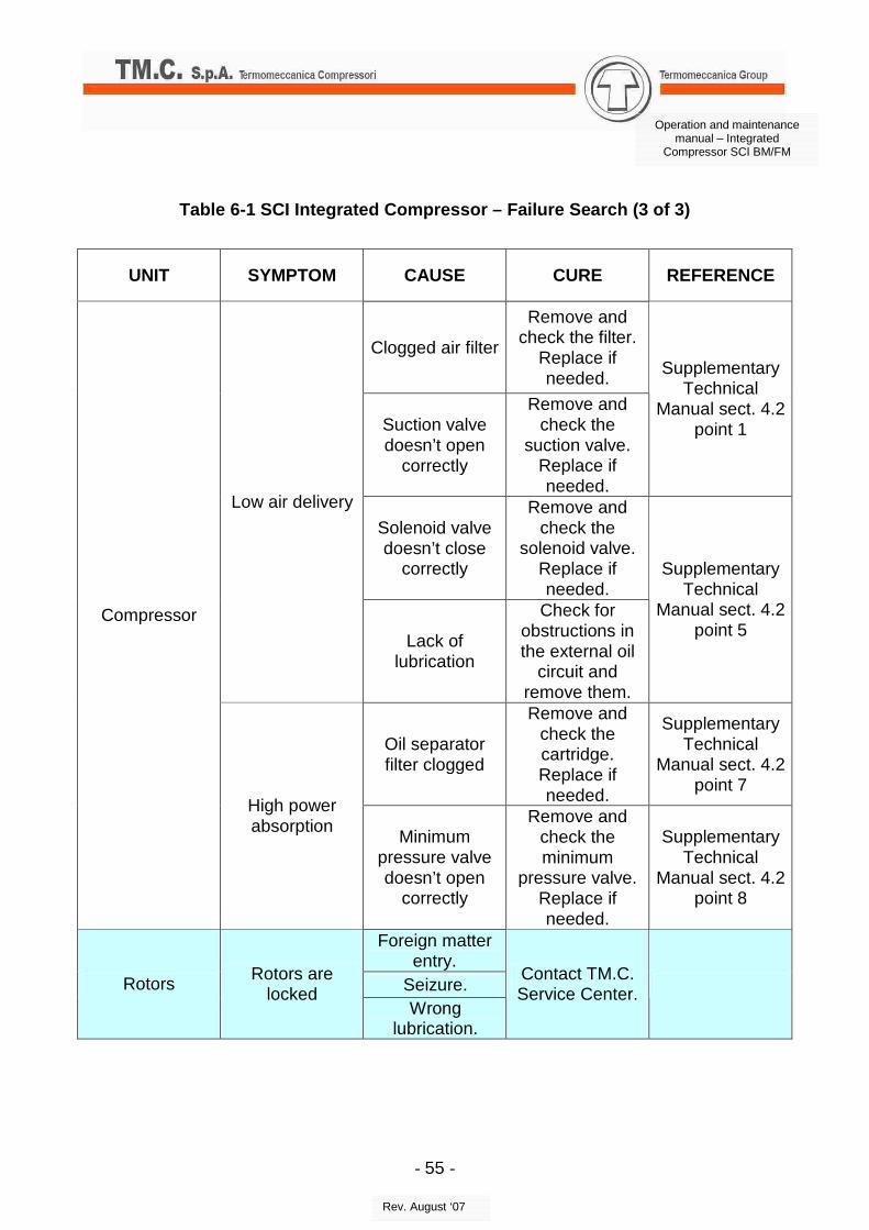
Table 6-1 SCI Integrated Compressor – Failure Searc h (3 of 3)
UNIT SYMPTOM CAUSE CURE REFERENCE
Clogged air filter
Remove and check the filter.
Replace if needed.
Suction valve doesn’t open
correctly
Remove and check the
suction valve. Replace if needed.
Supplementary Technical
Manual sect. 4.2 point 1
Solenoid valve doesn’t close
correctly
Remove and check the
solenoid valve. Replace if needed.
Low air delivery
Lack of lubrication
Check for obstructions in the external oil
circuit and remove them.
Supplementary Technical
Manual sect. 4.2 point 5
Oil separator filter clogged
Remove and check the cartridge. Replace if needed.
Supplementary Technical
Manual sect. 4.2 point 7
Compressor
High power absorption
Minimum pressure valve doesn’t open
correctly
Remove and check the minimum
pressure valve. Replace if needed.
Supplementary Technical
Manual sect. 4.2 point 8
Foreign matter entry.
Seizure. Rotors Rotors are
locked Wrong
lubrication.
Contact TM.C. Service Center.
- 56 -
Operation and maintenance manual – Integrated
Compressor SCI BM/FM
Rev. August ‘07
7. COMPLETE OVERHAUL
7.1. Introduction
The term complete overhaul implies the SCI Compressor disassembly, the thorough cleaning and an accurate check of all the parts thereof; the replacement of all the rubber parts and of other worn out or defective parts, the replacement of all the clamps. The rusty parts must be replaced or repainted.
This section contains the instructions needed to disassemble, replace and overhaul all the parts constituting the SCI Compressor.
The maintenance staff must strictly observe the maintenance procedures, and particularly the general safety regulations.
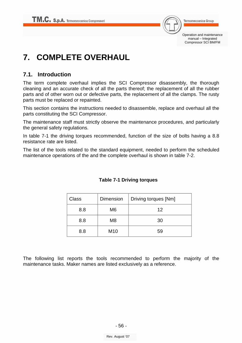
In table 7-1 the driving torques recommended, function of the size of bolts having a 8.8 resistance rate are listed.
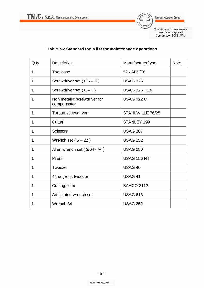
The list of the tools related to the standard equipment, needed to perform the scheduled maintenance operations of the and the complete overhaul is shown in table 7-2.
Table 7-1 Driving torques
Class Dimension Driving torques [Nm]
8.8 M6 12
8.8 M8 30
8.8 M10 59
The following list reports the tools recommended to perform the majority of the maintenance tasks. Maker names are listed exclusively as a reference.
- 57 -
Operation and maintenance manual – Integrated
Compressor SCI BM/FM
Rev. August ‘07
Table 7-2 Standard tools list for maintenance opera tions
Q.ty Description Manufacturer/type Note
1 Tool case 526.ABS/T6
1 Screwdriver set ( 0.5 – 6 ) USAG 326
1 Screwdriver set ( 0 – 3 ) USAG 326 TC4
1 Non metallic screwdriver for compensator
USAG 322 C
1 Torque screwdriver STAHLWILLE 76/25
1 Cutter STANLEY 199
1 Scissors USAG 207
1 Wrench set ( 6 – 22 ) USAG 252
1 Allen wrench set ( 3/64 - ¼ ) USAG 280”
1 Pliers USAG 156 NT
1 Tweezer USAG 40
1 45 degrees tweezer USAG 41
1 Cutting pliers BAHCO 2112
1 Articulated wrench set USAG 613
1 Wrench 34 USAG 252
- 58 -
Operation and maintenance manual – Integrated
Compressor SCI BM/FM
Rev. August ‘07
7.2. Instructions on reference documents for comple te overhaul of a specific SCI model
It is necessary to complete the advice given in this manual with the information included in the Supplementary Technical Manual (MTI) specific for each machine, before proceeding with the complete overhaul of the compressor.
Ask for the specific Supplementary Technical Manual while purchasing a SCI compressor model.
In the MTI, the user can find all the information related to the specific SCI compressor model (technical data, maintenance card, reference drawings, etc.).
Together with this manual, the use of MTI is needed to operate on a SCI compressor.
The customer should refer to the specific MTI every time it is requested in this manual.
- 59 -
Operation and maintenance manual – Integrated
Compressor SCI BM/FM
Rev. August ‘07
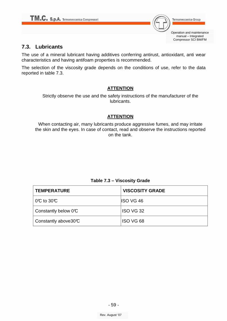
7.3. Lubricants
The use of a mineral lubricant having additives conferring antirust, antioxidant, anti wear characteristics and having antifoam properties is recommended.
The selection of the viscosity grade depends on the conditions of use, refer to the data reported in table 7.3.
ATTENTION
Strictly observe the use and the safety instructions of the manufacturer of the lubricants.
ATTENTION
When contacting air, many lubricants produce aggressive fumes, and may irritate the skin and the eyes. In case of contact, read and observe the instructions reported
on the tank.
Table 7.3 – Viscosity Grade
TEMPERATURE VISCOSITY GRADE
0°C to 30°C ISO VG 46
Constantly below 0°C ISO VG 32
Constantly above30°C ISO VG 68
- 60 -
Operation and maintenance manual – Integrated
Compressor SCI BM/FM
Rev. August ‘07
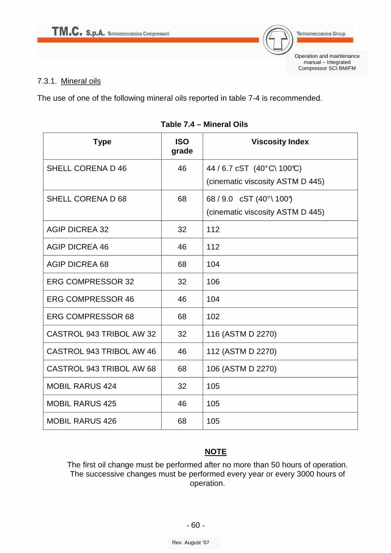
7.3.1. Mineral oils
The use of one of the following mineral oils reported in table 7-4 is recommended.
Table 7.4 – Mineral Oils
Type ISO grade
Viscosity Index
SHELL CORENA D 46 46 44 / 6.7 cST (40° C\ 100°C)
(cinematic viscosity ASTM D 445)
SHELL CORENA D 68 68 68 / 9.0 cST (40° \ 100°)
(cinematic viscosity ASTM D 445)
AGIP DICREA 32 32 112
AGIP DICREA 46 46 112
AGIP DICREA 68 68 104
ERG COMPRESSOR 32 32 106
ERG COMPRESSOR 46 46 104
ERG COMPRESSOR 68 68 102
CASTROL 943 TRIBOL AW 32 32 116 (ASTM D 2270)
CASTROL 943 TRIBOL AW 46 46 112 (ASTM D 2270)
CASTROL 943 TRIBOL AW 68 68 106 (ASTM D 2270)
MOBIL RARUS 424 32 105
MOBIL RARUS 425 46 105
MOBIL RARUS 426 68 105
NOTE
The first oil change must be performed after no more than 50 hours of operation. The successive changes must be performed every year or every 3000 hours of
operation.
- 61 -
Operation and maintenance manual – Integrated
Compressor SCI BM/FM
Rev. August ‘07
7.3.2. Synthetic oils
Alternatively to the mineral oils, synthetic oils can be used as well, capable of prolonging the time between oil changes and the working life of the various components (filters etc..). The list is reported in table 7.5.
Table 7.5 - Synthetic Oils
Type ISO grade
Viscosity Index
SHELL CORENA AS 46 46 46 / 83 Cst (40° C / 100° C)
The areas of the compressor where the paint is damaged must be repaired to prevent further decay.
The areas to paint must be clean, dry and free of rust. If the rust is already present it will be necessary to perform a sand blasting of the area at issue and an integral cleaning thereof before applying the paint in accordance with the following directions.
Electrostatic painting
This is carried out by means of suitable equipment that permits atomization of the paint product and brings the particles to a high electric potentiality by means of a high voltage source.
These particles are attracted by means of the electrostatic field of the surface to be painted that has a charge that is opposite to that of the particles.
Main features of this method are:
• a complete coating effect;
• a good distribution of the product;
• limited product loss.
6.1. Handling To handle the compressor it is necessary to use an eye bolt, fixed to the appropriate hole on the machine. It is necessary to lock the compressor during handling to avoid any ranger or touch.
- 63 -
Operation and maintenance manual – Integrated
Compressor SCI BM/FM
Rev. August ‘07
8. SPECIAL TOOLS
8.1. Introduction
To proceed with the disassembly/assembly and to ad just the SCI compressor, it is necessary to use in some phases some apposite special tools.
These tools are specifically designed to perform particular operations.
8.2. Instructions on reference documents for descri ption and use of a specific special tool
The specific information regarding the special tools are included in the Supplementary Technical Manual (MTI) specific for each machine.
Ask for the specific Supplementary Technical Manual while purchasing a SCI compressor model.
In the MTI, the user can find all the information related to the specific SCI compressor model (technical data, maintenance card, reference drawings, etc.).
Together with this manual, the use of MTI is needed to operate on a SCI compressor.
The customer should refer to the specific MTI for the data regarding special tools.