When the equipment is received, each shipping container should be carefully examined for anyevidence of mishandling during shipment. Note its condition, if abnormal, carefully unpack allparts and examine for damage. If any damage is noted, immediately report it to the carrier in theproper manner. All printed matter supplied with the unit should be saved for installation,operation, and future reference.
Notes
Page 3Page 18
Introduction
Purpose
The ARU-01CF Command Air X-ray System provides a portable and practical way to obtaindental radiographs in the field. To receive the best service and longest life from your Asepticoproduct, follow the instructions detailed in this manual.
1 Measurements taken with a 50mm diameter sphere gap.2 The stated mA and line current are under conditions of input line voltage of 110 - 130 V (220 - 260 V)
with 2 ~ 5% regulation. If regulation is less, the amps drawn and mA can be higher than stated.3 Using a precise DC mA meter across points N and NE of the high tension transformer (see schematic
diagram) to measure mA. Input is 117 V AC (230 V AC), 50/60 Hz. Tolerance is ± 15%.
Notes
Page 17Page 4
Safety Precautions
WARNING - Careless or improper use of x-ray equipment can be extremely hazardous.
WARNING - It is imperative that this equipment be operated and serviced only by trainedpersonnel familiar with the safety precautions required to prevent excessive exposureto primary x-ray radiation, the dangers of exposure to x-ray radiation, and the properuse of the equipment discussed in this manual.
1. During exposure, the operator must stand as far as possible from the patient being x-rayedand should wear a lead apron or stand behind a lead shield.
2. The operator must not stand in the primary x-ray beam.
3. The operator must wear a monitoring badge while operating this unit. It should be on thecollar, not on an area covered by the lead apron.
4. X-ray exposure should be as short as possible.
All personnel authorized to operate or service this equipment should be fully acquainted with theestablished maximum permissible doses, safety recommendations, and procedures derived fromthe following sources:
A. National Council on Radiation Protection Report No. 33 (Medical X-ray and Gamma RayProtection for Energies up to 10 MEV - Equipment Design and Use); from NCRPPublications; P.O. Box 30175, Washington, D.C. 20014.
B. National Bureau of Standards Handbook No. 76 (Medical X-ray Protection up to ThreeMillion Volts); from the Superintendent of Documents, Government Printing Office,Washington, D.C. 20401.
C. All documents relating to the Performance Standard for Diagnostic X-ray Systems, 21 CFRSubchapter J, Part 1020; obtainable from FDA Center for Devices and RadiologicalHealth, Department of HHS, 2098 Gaither Road, Rockville, MD 20850.
D. State and local regulations governing radiation protection and the use of diagnostic x-rayequipment.
E. Requirements of the user's in-house radiation protection program.
F. Instructions and precautionary notices of this manual.
Although this equipment incorporates protective design features for limiting both the direct(primary) x-ray beam and the secondary radiation produced by this beam, design factors alonecannot prevent human carelessness, negligence, or lack of knowledge. This apparatus is sold withthe understanding that the user assumes sole responsibility for radiation safety and that Aseptico,Inc., its agent and representatives, do not accept any responsibility for:
1. Injury or danger to patient or other personnel from x-ray exposure.
2. Overexposure due to poor operating techniques or procedures.
3. Equipment not properly serviced or maintained in accordance with this manual.
4. Equipment which has been modified or tampered with in any way.
Notes
Page 5Page 16
mA
outp
ut
mA
outp
ut
CN
3
LV
RS
WL
VR
SW
off
F1
10A
F1
10
A
CN
1A
C1
20
VC
N1
AC
12
0V
VA
R1
VA
RIS
TO
R
SS
R1
T1
CN
2
4 3 2 14 3 2 1
65
90
2-0
04
X-R
AY
LE
DX
-RA
YL
ED
X-R
AY
SW
X-R
AY
SW
Vcc
1 2 3 4 5 6 71 2 3 4 5 6 7 4 3 2 14 3 2 1
12
11
10 9 8 7 6 5 4 3 2 1
12
11
10 9 8 7 6 5 4 3 2 1
Vcc
SS
R(-
)
AC
12
V
AC
12
V
JP2
JP1
JP3
PC
B109
3
D1
R1
20
W/1
0R
12
0W
/10
off
1
LV
RS
WL
VR
SW
1 2 3 4 5 6 7 8 91 2 3 4 5 6 7 8 9
1 2 3 4 5 6 7 8 91 2 3 4 5 6 7 8 9
mA
+
mA
-
0V
11
0V
11
5V
12
0V
12
5V
13
0V
CN
4
31
91
-9R
31
91
-9P
31
91
-9R
31
91
-9P
mA
+m
A-
0V
110V
11
5V
120V
125V
130V
T1
R1
X-R
AY
TU
BE
D-0
82B
X-R
AY
TU
BE
D-0
82B
YE
LL
OW
EX
PO
SU
RE
YE
LL
OW
EX
PO
SU
RE
RE
DO
VE
RR
ED
OV
ER
GR
EE
NC
EN
TE
RG
RE
EN
CE
NT
ER
RE
DU
ND
ER
RE
DU
ND
ER
2
LV
RS
WL
VR
SW
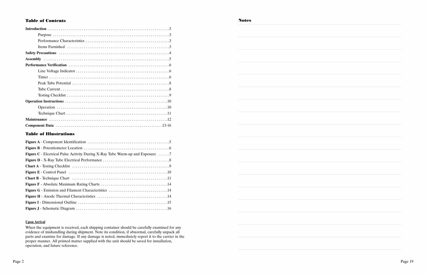
Figure J - Schematic Diagram
Aseptico ARU-01CF X-Ray System (MinXray P200D Mark III)
1
2 3 4
Figure A - Component Identification
Assembly
1. Remove the x-ray tube head and control, cone, exposure cord, and power cord from thecarrying case.
2. Screw the cone on to the front of the tubehead.3. Plug the exposure cord into the rear of the tubehead.4. Plug the power cord into the rear of the tubehead5. Set up tripod6. Attach the assembled x-ray unit to the stand.7. Check the line voltage and the voltage on the rating label;
115 V type requires line voltage between 110 and 130 V.230 V type requires line voltage between 220 and 260 V.These voltages must be with 15 ampere #12 three-wire service, if not,the films may be light or show lack of sufficient penetration.
8. Plug the power cord into the wall outlet.The unit is now assembled and ready for testing.
Since the filament of the x-ray tube is off when the unit is not emitting radiation, it takesapproximately 0.15 seconds (9 electrical pulses) for the x-ray tube filament to warm up be fore anx-ray is emitted (see Figure C). Because of this warm up time, the electronic timer has a built inlag of approximately 0.15 seconds, therefore, when checking the timer with a cycle counter, 0.15seconds must be added to the time set on the timer.
� 9
519
51
±2
51
102
±5
M5, 8 DEEP
� 24
FOCAL SPOT
5M
AX
13
MA
X
50
MIN
� 31 MAX
F: FILAMENTC: CATHODE
C C
C
CF
F
60°
SHORT PIN
CENTRAL X-RAY
Terminals “C” are connectedmutually inside the tube.
SCALE= 1:1
UNITS= mm
�
� ±17.25 0.1
Figure I - Dimensional Outline
Toshiba D-082B Stationary Anode X-Ray Tube
Performance Verification
The following tests must be conducted without fail before the ARU-01CF Command Air X-RaySystem can be used for radiology. Fill out the checklist for these tests when installation of x-rayunit is complete.
Line Voltage (LV) Indicator
1-1 LV Indicator Test Method:
Measure voltage of wall outlet, and confirm that the following conditions are fulfilled.
Wall outlet voltage:
130 ~ 125 V (260 ~ 250 V) Green LED goes on when LV knob turns 1 click clockwise.125 ~ 120 V (250 ~ 240 V) Green LED goes on when LV knob turns 2 clicks clockwise.120 ~ 115 V (240 ~ 230 V) Green LED goes on when LV knob turns 3 clicks clockwise.115 ~ 110 V (230 ~ 220 V) Green LED goes on when LV knob turns 4 clicks clockwise.110 ~ 105 V (220 ~ 210 V) Green LED goes on when LV knob turns 5 clicks clockwise.
If the LV indicator needs adjustment:
1. Remove the 4 screws on the cover.2. Adjust the potentiometer "A" (See Figure B) on the printed circuit board so that the green
LED goes on at the above settings.3. Replace the cover and the 4 screws.
+
-
A
B
Figure B - Potentiometer Location
Figure I - Dimensional Outline
Page 7Page 14
0.1 0.2 0.3 0.5 0.7 1 2 3 5 7 106
8
10
12
14
16
18
20
TU
BE
CU
RR
EN
T(m
A)
EXPOSURE TIME (s)
70 kV
60 kV
50 kV
0
5
10
15
20
1.5 1.6 1.7 1.8 1.9 2.0
2.0
2.5
3.0
3.5
FILAMENT CURRENT (A)
TU
BE
CU
RR
EN
T(m
A)
FIL
AM
EN
TV
OL
TA
GE
(V)
60 kV
E�
0 1 2 3 40
1
2
3
4
5
6
7
210
W
170 W
130 W
HEATING
COOLING
TIME (min)
HE
AT
ST
OR
AG
E(k
J)
Figure F - Absolute Maximum Rating Charts
SELF RECTIFIED FOCAL SPOT: 0.8 mm
SELF RECTIFIED
Figure H - Anode Thermal Characteristics
Figure G - Emission and Filament Characteristics
Figures F, G, & H - Standard Value Charts
Toshiba D-082B Stationary Anode X-Ray Tube
Exposure start
Exposure end
Visible Pulses
Warm-up Time Exposure Time
Total Electrical Pulses
Figure C - Electrical Pulse Activity During X-Ray Tube Warm-up and Exposure
2-1 Timer Test Method:
1. Set timer to 0.08 sec.2. Set NERO to the following settings.
NERO Model 6000M X-ray Beam Analyzer, Manufactured by Victoreen, Inc. or equivalent
2-3 Rejection Limit:
± 2 pulse (0.08 sec. ~ 2.0 sec.), ± 10% (0.25 sec. ~ 2.0 sec.)
If the timer needs adjustment:
1. Remove the 4 screws on the cover.2. Adjust the potentiometer "B" (See Figure B) on the printed circuit board so that the radiation
exposure time equals the time indicated on the timer dial, taking into consideration theaccuracy tolerances.
3. Replace the cover and the 4 screws.
TW = P - Dx
TW = Filament warm-up time
P = Total number of electrical pulses
Dx = Number of readable dots on film as determined by a spin top test
Page 13Page 8
Peak Tube Potential
The ARU-01CF has a filament warm-up time of 0.15 sec. (9 electrical pulses) built into itssettings. The kV is as shown on Figure D. For that reason, measure kV with 0.15 sec. delay time.
Tube Current
The ARU-01CF has a filament warm-up time of 0.15 sec. (9 electrical pulses) built into itssettings. The kV is as shown on Figure D. For that reason, measure kV with 0.15 sec. delay time.
4-1 Tube Current Test Method:
1. Set timer to 2.0 sec.2. Connect the DC-mA meter to the pin jack terminal on rear panel.3. Make exposure and measure the mA value.4. Measure High value of ch2 at the following kV settings, and timer to 2.0 sec. with same
procedure.
4-2 Instruments:
Portable standard DC ammeter Model 2011 Yokogawa Electric Works, Ltd. or equivalent
4-3 Rejection Limit:
± 15%
0 0.15 sec
kVp
80
63
mA
12Tube Current
Peak Tube Potential
3-1 Peak Tube Potential Test Method:
1. Set timer to 0.2 sec.2. Set NERO to the following settings:
Cautions for the Toshiba D-082B Stationary Anode X-ray TubeSince the X-ray tube will emit x-rays when it is energized with high voltage, special knowledge is required to handle it. The items below show general cau-tions for the tube.
1. The tube shall be handled or operated only by qualified personnel. Only a specialist who has good knowledge of the x-ray tube should assemble,maintain, and remove the tube.
2. The tube envelope is made of glass. In transporting and handling the tube, sufficient care should be taken to avoid strong impacts or vibrations.
3. Adequate radiation protection must be used in the unit assembled with the tube. The leakage technique factor of the tube unit must not exceed themaximum anode cooling rate of the tube.
4. Fulfill the regulations and standards for the minimum source-skin distance (SSD) and the minimum filtration of the useful beam before using tube.
5. The tube might be broken by only one overload operation. Provide a proper overload protection circuit. Operate the tube by selecting a proper inputcondition according to the conditions for operation and tube characteristics charts.
6. If any abnormality is found when using this tube, immediately cut off the power supply and contact the TOSHIBA service department.
7. The following data sheet charts indicate standard values.
Page 9Page 12
Maintenance:
The following must be checked at least every six (6) months.1. Tubehead
A. Make sure certification and identification labels are in place.B. Check for any loose or missing screws.C. Check for oil leaks.D. Check for any physical damage.E. Check the LV knob for proper operation.F. Check the timer for proper operation.G. Check all the cord connections.H. Check the exposure button; the exposure must terminate if the button is released during an
exposure.
2. Beam Limiting Device (Dental Cone)A. Make sure the certification label is on the cone.B. Check for any physical damage.
3. IndicatorsA. Make sure the green light goes on when the LV knob is turned to the right from the off
position.B. Check the x-ray "ON" light for proper operation.C. Make sure the audible signal operates during an exposure.
Chart A - Testing Checklist
Complete this check list when assembly and testing are complete.
Serial Number:
Date Manufactured: Equipment Location:
Test Acceptance Results CheckDescription Limits
Line Voltage 110 ~ 130 V V GO NO GO(220 - 260 V)
Line Voltage 2 ~ 5% % GO NO GORegulation
Peak Tube 63 kVp ± 15% kVp GO NO GOPotential
Tube Current 12 mA ± 15% mA GO NO GO9.5 mA ± 15% mA
Exposure Time 0.08 sec ± 2 pulse sec GO NO GO0.1 sec ± 2 pulse sec0.2 sec ± 2 pulse sec
Instruments Used Manufacturer Model Accuracy Last Calibrated
Page 11Page 10
Operation Instructions
It is assumed by the distributors and manufacturer of the equipment that the person responsiblefor its operation has a general knowledge of the use of x-rays, including the precautions whichmust be taken.
Note: Confirm the wall outlet voltage and the voltage on the rating label of the ARU-01CF beforeconnecting the power cord.
Operation:
1. Position the tubehead for the radiograph desired.2. Line voltage compensation. Turn the LV knob clockwise until the center green LED lights. The
green LED must be lit before each exposure.3. Radiology
A. After positioning the patient and adjusting the line voltage compensator, set the electronictimer for the desired time. The following technique chart can be used as a guide.
B. Stand as far as possible from the x-ray unit, press the exposure switch to initiate the exposureand keep it pressed for the duration of the exposure. During the exposure, there will be anaudible signal and the "X-ray" light will illuminate on the unit.
C. The timer will automatically recycle; e.g. successive exposures can be made at the previouslyset time by merely pressing the exposure button.
D. An exposure can be interrupted at any time by releasing the exposure button.E. When an exposure is terminated, the "X-ray" light goes out and the audible signal ends.
Line VoltageSelector
TimerControl
Exposure CordReceptacle
Power CordReceptacle
X-Ray L.E.D.(Yellow)
Line VoltageL.E.D. (Green)
Figure E - Control Panel
Operation Precautions:
1. During exposure, the operator must stand as far as possible from the patient being x-rayed andshould wear a lead apron or stand behind a lead shield.
2. The operator must not stand in the primary x-ray beam.3. The operator must wear a monitoring badge while operating this unit. It should be on the collar,
not on an area covered by the lead apron.4. X-ray exposure should be as short as possible.
Chart B - Technique Chart
Exposure Time and Angulation of Central RayNote: Exposure times are intended as guides only.They are based on averages and may be modified to suit the individual patient.When modifying exposure times, the increase or decrease should be made in steps of 20-25%.