Engineering Journal of Qatar University, Vol. 5, 1992, p. 265-285 OPERATION AND MAINTENANCE OF SEWAGE TREATMENT PLANT IN DOHA Fawzi T. Shadid* and Shamim Ahmed** *Manager, Sewage Treatment Plant, Doha West, Ministry of Municipal Affairs and Agriculture, Qatar **Professor, Department of Civil Engineering, Qatar University, Doha-Qatar (First Received June 1992; accepted in revised form October 1992) ABSTRACT The sewage treatment plant in Doha-South uses primary, secondary and tertiary treatment units for treating predominantly domestic sewage. The treated effluent, is used in irrigating agricultural farms for growing animal fodder and in landscape irrigation in Doha. The stabilized sludge is used as a soil conditioner. Samples are collected regularly at the plant inlet as well as before and after each treatment process. The raw sewage is characterized by high dissolved solids, medium strength BOD, low COD/BOD ratio, high concentration of chloride, sulphate and sulfide due to septic sewage. These are typical characteristics of the sewage in this region. The plant is designed, operated and maint,ined so as to ensure safety and reliability in the treated effluent quality. Any overloading of the treatment processes is handled effectively. The reclaimed ·later quality meets the internation- al standards and guidelines for landscape irrigation and farming. No evidence of disease amongst workers or the public has been observed from the water reuse. INTRODUCTION The municipal sewage treatment in Doha is predominantly domestic in character. The sewage treatment plant uses primary, secondary and tertiary treatment units. A schematic flow diagram of the unit operations and flow processes is given in Fig. 1. Both pre- and post- chlorination are practiced. The sludge is anaerobically digested, dewatered and dried. The treated effluent is used in irrigating agricultural farms for growing animal fodder and landscape irrigation. Any excess reclaimed water is stored in balancing tanks or pumped to the natural depressions outside the city. The stabilized sludge is used as a soil conditioner. The construction, operation and maintenance costs of the sewage treatment plant are fully financed by the State of Qatar. The reclaimed water quality meets the international. standards and guidelines for landscape irrigation and farms (Ahmed, 1989). No evidence of disease amongst workers or the pubHc has been observed arising from the water reuse (Banks, 1991). The objective of this paper is to discuss the strategy used in the design, operation and maintenance of the treatment plant so as to ensure safety and reliability in the 265
Transcript
Engineering Journal of Qatar University, Vol. 5, 1992, p. 265-285
OPERATION AND MAINTENANCE OF SEWAGE TREATMENT PLANT IN DOHA
Fawzi T. Shadid* and Shamim Ahmed** *Manager, Sewage Treatment Plant, Doha West, Ministry of Municipal Affairs and Agriculture, Qatar
**Professor, Department of Civil Engineering, Qatar University, Doha-Qatar (First Received June 1992; accepted in revised form October 1992)
ABSTRACT
The sewage treatment plant in Doha-South uses primary, secondary and tertiary treatment units for treating predominantly domestic sewage. The treated effluent, is used in irrigating agricultural farms for growing animal fodder and in landscape irrigation in Doha. The stabilized sludge is used as a soil conditioner. Samples are collected regularly at the plant inlet as well as before and after each treatment process. The raw sewage is characterized by high dissolved solids, medium strength BOD, low COD/BOD ratio, high concentration of chloride, sulphate and sulfide due to septic sewage. These are typical characteristics of the sewage in this region.
The plant is designed, operated and maint,ined so as to ensure safety and reliability in the treated effluent quality. Any overloading of the treatment processes is handled effectively. The reclaimed ·later quality meets the international standards and guidelines for landscape irrigation and farming. No evidence of disease amongst workers or the public has been observed from the water reuse.
INTRODUCTION
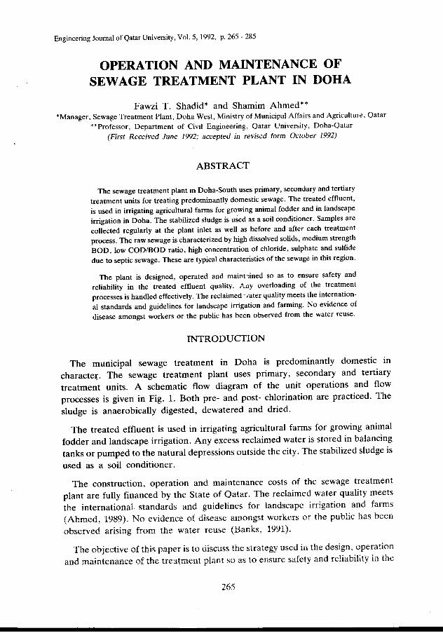
The municipal sewage treatment in Doha is predominantly domestic in character. The sewage treatment plant uses primary, secondary and tertiary treatment units. A schematic flow diagram of the unit operations and flow processes is given in Fig. 1. Both pre- and post- chlorination are practiced. The sludge is anaerobically digested, dewatered and dried.
The treated effluent is used in irrigating agricultural farms for growing animal fodder and landscape irrigation. Any excess reclaimed water is stored in balancing tanks or pumped to the natural depressions outside the city. The stabilized sludge is
used as a soil conditioner.
The construction, operation and maintenance costs of the sewage treatment plant are fully financed by the State of Qatar. The reclaimed water quality meets the international. standards and guidelines for landscape irrigation and farms (Ahmed, 1989). No evidence of disease amongst workers or the pubHc has been observed arising from the water reuse (Banks, 1991).
The objective of this paper is to discuss the strategy used in the design, operation and maintenance of the treatment plant so as to ensure safety and reliability in the
265
Fawzi T. Shadid and Shamim Ahmed
Screenings Grit Disposo.l Disposo.l
Dried s tudge di sposo. t
To Alou Nukh luh < Lo. ter to Govt , Fo.rM)
Tertio.ry Treo.i:Ment fl l ters
Effluent Tower
To Doha TSE Network
Fig. 1: Schematic flow diagram of sewage treatment plant
treated effluent quality. The various treatment operations, components and systems of the plant are described herein. The main equipment and units of the treatment plant, are given in Table 1. The greater part of the plant structures are
Table 1 List of Main Equipment and Units
Sr. Equipment Capacity No. No.
1. Screens machinery raked curved bar screens with 20 mm spaces 4
screenting press and bagging machine 0.5 m3/h 1
2. Grit removals removes 0.3 mm grit at 610 1/s 4
3. Primary settling 22 m diameter, 2.3 m deep and floor
tanks slope 10 degrees with travelling bridge scraper and scum draw off 6
4. Aeration Tanks 12.0 X 12.0 x 4.0 deep containing one 1 surface aerator in 4 series of 3 pockets 1 per channel 18
- ----
266
I
5. Final settling tanks
Operation and Maintenance of Sewage Treatment Plant
Table 1 Contd.
24.0 m diameter with floor slope of 30 degrees with travelling bridge scraper and scum draw off 6
6.
7.
8.
9.
10.
11.
Effuent balancing tank
Chlorination
Tertiary treatment sand filters
Primary sludge consolidation tanks
Surplus activated sludge thickners
Primary digesters
10,000 m3 capacity
pre and post chlorination.
8.0 x 9.0 x 1.0 m deep
each tank with low level scraper to pump, 160m3 capacity
each unit accepts 25 Lis at 5g/l sludge solids concentration
18.0 m diameter, 2656 m3 capacity with floating roof gas storage under bell 770m3
12. Secondary digesters 17.0 m diameter, 948 m3 capacity open
1
2
14
2
5
4
tanks with decanter dewatering valves 4
13. Sludge pressing plant presses containing 82 plates, each 1.2 x 1.2 m, capacity 42 m3 of sludge at 3%. Polyelectrolyte mixers and feeding pumps 6
constructed above the ground because of the high cost of construction, due to difficulty of excavation caused by the hard rocky ground.
The various process components must be routinely taken out of service for repairs, painting and other maintenance functions. For this reason each unit process has a duplicate to permit continuity in treatment whenever any unit is out of service. The out of service unit can be dewatered as well.
267
Fawzi T. Shadid and Shamim Ahmed
Intake Works and Screening
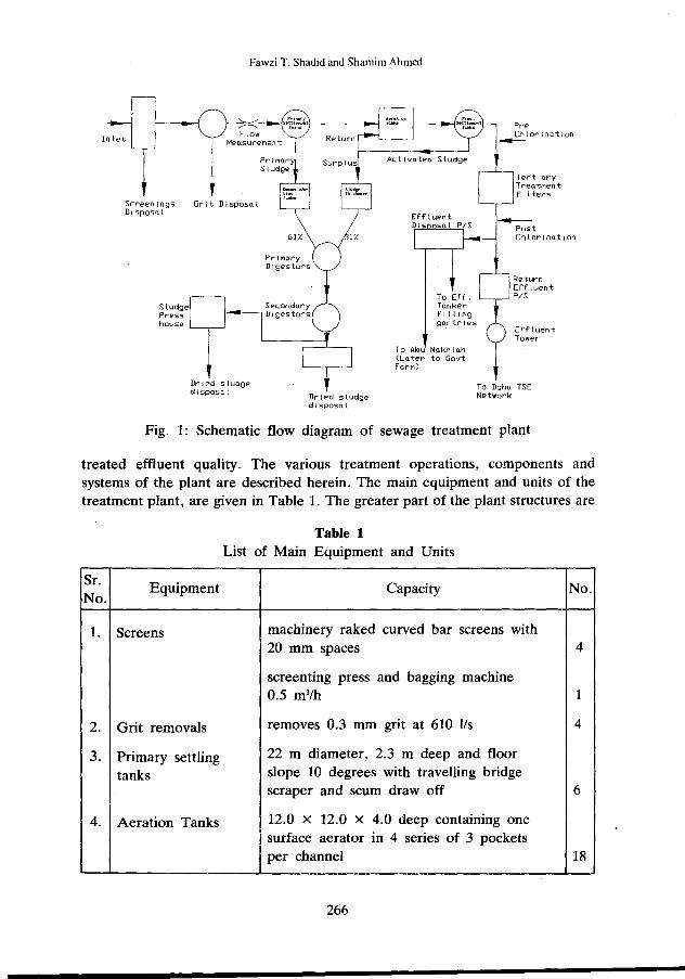
The pumped sewage from the city of Doha enters the plant at a height of about 7 m above the ground level so that it could flow under gravity though the primary and secondary units (Fig. 2). It then flows through four curved mechanically raked bars with 20 mm openings which remove objects like rags, papers, plastic and large floating matters, so as not to block subsequent stages of treatment. The screens are cleaned by mechanical combs operated intermittently by timer. Pieces of buoyant solids and plastics which succeed in passing the screens are removed manually by the operators, otherwise these may interfere with the operation of sludge mixing pumps.
Fig. 2: Inlet Works: Racks and detritors with the new effluent tower m the background.
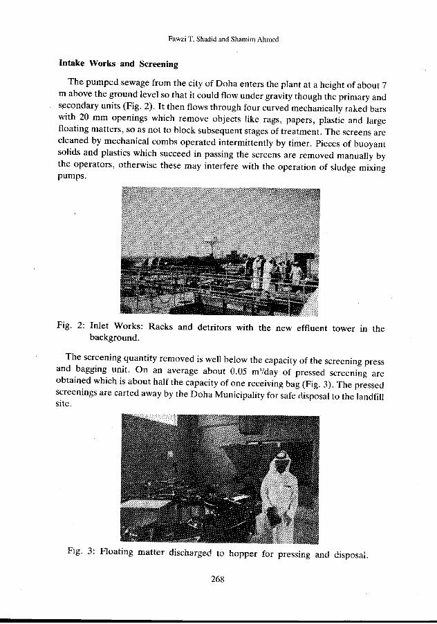
The screening quantity removed is well below the capacity of the screening press and bagging unit. On an average about 0.05 m'/day of pressed screening are obtained which is about half the capacity of one receiving bag (Fig. 3). The pressed screenings are carted away by the Doha Municipality for safe ciisposal to the landfill site.
Fig. 3: Floating matter discharged to hopper for pressing and disposal.
268
Operation and Maintenance of Sewage Treatment Plant
Detritus Tanks
Four circular detritus tanks (Dorr-Detritor) are used for the removal of grit (Escritt, 1984), which otherwise would cause unduly rapid wear and tear of the mechanical equipment including leather seals of piston pumps.
Sewage from the screening plant flows along a channel to grit collection tanks at a velocity high enough to prevent settling of solid matter. At the inlet to tank a deflector arrangement consisting of twelve baffles directs the flow over the complete width of the tank (Fig. 4). Due to the increase in width and depth of flow the velocity across the tank is reduced. Details of the tank are given in Fig. 4. Sewage flows across the basically square plan to the outlet weir. sufficiently slowly and evenly for grit particles down to 0.2 - 0.3 mm size to settle.
Fig. 4: Detritors with grit removal equipments
The settled matter is deposited on a flat, circular central floor which is swept periodically by a grit scraper. Each scraper is a three-armed assembly driven by a bridge-mounted electric motor and gear unit. The action of the scraper is to collect the solids settled on the tank floor, pushing them towards the periphery and depositing them in a hopper which feeds the grit elevator trough.
The elevator is housed in a trough built just outside the area of the tank at a tangent to the peripheral motion of the scraper. The main element of the elevator is a reciprocating, multiplebar rake mechanism which propels grit, delivered to it by the scrapers, up the inclined trough. During this process the grit is washed and
269
Fawzi T. Shadid and Shamim Ahmed
lifted clear of the sewage level to a point where it drops into the skip provided on the ground surface.
In order that the grit raked out by the elevator be as free as possible from organic matter, an organic return washing system is provided, the main element being the washwater pump arrangement. The pump draws grit-free liquor from the collection tank through a rag screen and a short length of pipe to a sump directly connected with the grit elevator trough. The pump gives a slight increase in water level in the trough relative to the main tank; and the agitating action of the elevator allows light organic matter to be washed off the grit and returned to the collection tank over a fixed weir plate.
In the hand mode of operation all equipment may be started and stopped manually when required; however the normal mode of the Grit Removal Plant is automatic. Normal operation of the grit collection equipment associated with each tank is by time control. Each grit scraper operates for a predetermined period of up to 60 minutes with intervals between starts of up to 24 hours; a typical setting would be 45 minutes running every three hours. These values are set by timing devices in the Inlet Works Control Panel.
Primary Settling Tanks
Upward flow type circular shaped settling tanks are used to remove settleable solids, floating scum and grease from the raw sewage. The settleable solids are collected in the central hopper of the tank (Fig. 5.) A travelling bridge on each tank allows scum and sludge removal to a common collection chamber and then by gravity to the sludge consolidation tanks. Any greasy matter and algae collected on the side walls, over weirs and weir channels are cleaned manually.
Fig. 5: Primary setting tank
270
Operation and Maintenance of Sewage Treatment Plant
The main equipment installed in the tanks include, central column, fixed bridge, scraper assembly, central drive equipment, scum and grease collection equipment, scum board and outlet weir plates. Settled sewage passes over the outlet weirs to a common collection chamber before flowing to the aeration tanks. The primary settling tank reduces the suspended solids by 60% and the BOD by 25%.
Even at high hydraulic loadings the sludge holding capacity is such that primary desludging could be delayed for up to three days without carry over to the aeration tanks. Under normal conditions desludging is done on a daily basis with a sludge of 3 to 6% solid content.
Activated Sludge Process
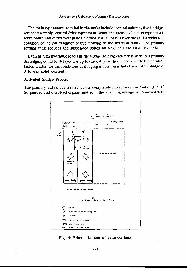
The primary effluent is treated in the completely mixed aeration tanks. (Fig. 6) Suspended and dissolved organic matter in the incoming sewage are removed with
L _.)_-_I- _j_ I
I
.(, KE'I'•
Mixed LiquDr to Flna.l s ... ttlel'lent Tank,;
p Dl,;solved Oxygen Meo.syrlng Probe
~ CJ Adj1.1stable Outlet Weir
Reot...-n o.ctlvo.ted :sludge
Fig. 6: Schematic plan of aeration tank
271
Fawzi T. Shadid and Shamim Ahmed
the help of microorganisms by adsorption, assimilation and oxidation. In the activated sludge process organic impurities are either converted to simple stabilized chemical compounds or assimilated into the cell of living microorganisms which are in the form of floes and can thus be separated from the sewage by settling (Mullick, 1987).
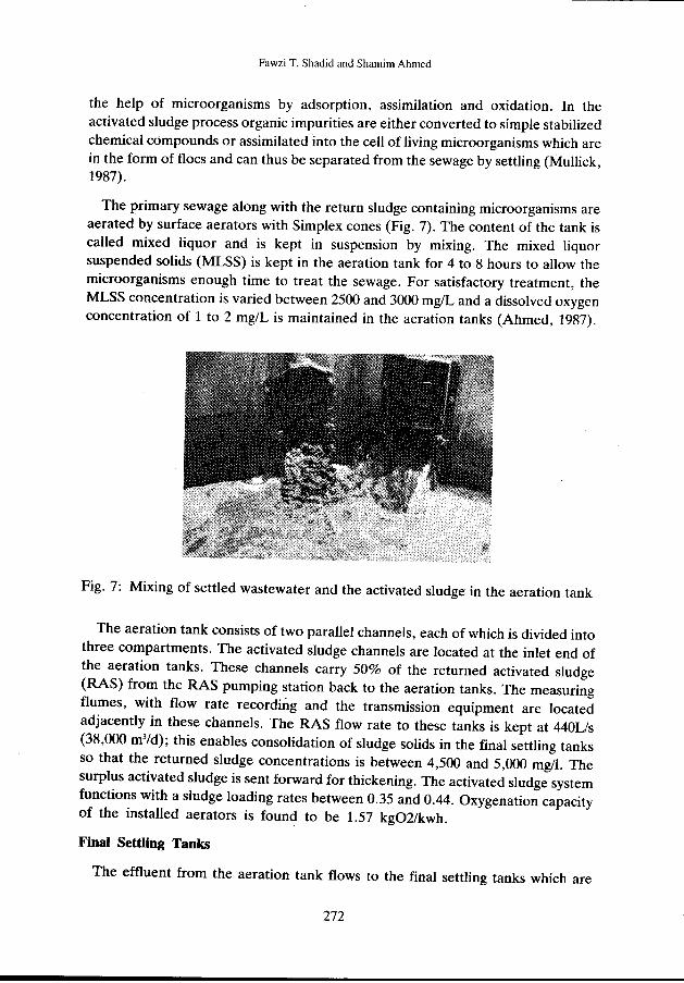
The primary sewage along with the return sludge containing microorganisms are aerated by surface aerators with Simplex cones (Fig. 7). The content of the tank is called mixed liquor and is kept in suspension by mixing. The mixed liquor suspended solids (MLSS) is kept in the aeration tank for 4 to 8 hours to allow the microorganisms enough time to treat the sewage. For satisfactory treatment, the MLSS concentration is varied between 2500 and 3000 mg/L and a dissolved oxygen concentration of 1 to 2 mg/L is maintained in the aeration tanks (Ahmed, 1987).
Fig. 7: Mixing of settled wastewater and the activated sludge in the aeration tank
The aeration tank consists of two parallel channels, each of which is divided into three compartments. The activated sludge channels are located at the inlet end of the aeration tanks. These channels carry 50% of the returned activated sludge (RAS) from the RAS pumping station back to the aeration tanks. The measuring flumes, with flow rate recording and the transmission equipment are located adjacently in these channels. The RAS flow rate to these tanks is kept at 440L/s (38,000 m3/d); this enables consolidation of sludge solids in the final settling tanks so that the returned sludge concentrations is between 4,500 and 5,000 mg/l. The surplus activated sludge is sent forward for thickening. The activated sludge system functions with a sludge loading rates between 0.35 and 0.44. Oxygenation capacity of the installed aerators is found to be 1.57 kg02/kwh.
Final Settling Tanks
The effluent from the aeration tank flows to the final settling tanks which are
272
Operation and Maintenance of Sewage Treatment Plant
circular with external diameter of 26.0 m, and an internal diameter of 24.0 m (Fig. 8). The internal side wall depth is 0.525 m. An outer coping walll.5 m high above ground level surrounds the tank forming a circumferential outlet channel.
The effluent sometimes shows the presence of filamentous organisms (Fig. 9), specially when the sludge volume index is larger than 150, indicating sludge bulking. Regular microscopic examination is carried out to detect the presence of the filamentous organisms. For controlling sludge bulking 5 to 6 mg/L of chlorine is added to the return sludge.
Fig. 8: Final setting tank with the rapid gravity filter beds in the background
Fig. 9: Filamentous organisms in the final effluent
Tertiary Treatment
Tertiary treatment is given to the effluent coming out of the secondary treatment because the reclaimed water is meant to be used for landscape irrigation in an
273
Fawzi T. Shadid and Shamim Ahmed
urban environment where children and adults are used to consider water coming out of a tap safe. The effluent from the final settling tanks is raised by screw pumps (Fig. 10) to rapid sand gravity filters.
The filters are operated in automatic mode under normal circumstances with backwashing for each filter in sequence at 24 hour intervals. If a secondary effluent of high quality is received the measured head loss through the filters is only 0.1 to 0.2 m. In this case the filters could run for 60 hours without backwashing. Whenever there are exceptionally high flows or operational problems the increasing head loss across all filters is usually offset by manually initiated backwash of each unit. The treated effluent produced after tertiary treatment has a suspended solid less than 10 mg!L and a 5-day BOD of less than 10 mg/L. The tertiary treatment unit is capable of handling 202,000 m3/d, of biologically treated sewage.
Fig. 10: View of screw pumps
Chlorination
Liquid chlQTine is added before tertiary treatment filtration to prevent algae blinding of sand filters and to kill pathogens. Disinfection of the final effluent is also done using liquid chlorine to maintain a residual chlorine concentration fo 0.5 mg!L even at the extreme end of the irrigation network. Microbiological quality of the treated effluent is below the maximum coliform count of 100/100 ml of sample on an average of 85% of the samples analyzed. The Ministry of Public Health Laboratories and the Laboratory at the treatment plant have reported absence of E-Coli in the samples collected in various locations of the irrigation network.
The final effluent is pumped to the effluent tower for reuse in the city irrigation network and to the agricultural farms. Four variable speed pumps are used to
274
Operation and Maintenance ofSell'age Treatment Plant
transfer the treated effluent to the agricultural farms and to the storage lagoons. Four double outlet tanker filling gantries are installed at the treatment works to fill road tankers for use in those areas of the city which are not covered by the irrigation network.
Sludge Treatment
The primary setting tanks are manually desludged on daily basis to the consolidation tanks. After settling, the supernatant water is decanted off to the intake works; and the remaining sludge is pumped to sludge digesters. The consolidated sludge has a solids content of about 6%.
The surplus activated sludge contains about 0.5% solids which is too bulky to handle, therefore dissolved air floatation units (DAF) are used to thicken the surplus activated sludge. Each unit has a design capacity of 25 Lis of sludge at 5,000 mg/L concentration to produce a flow containing 5% solids. Polyelectrolyte is used to assist in concentrating the sludge to 7% solids at a feeding rate of 0. 7 kg/h using a special dosing pump.
The sludge is pumped through an air pressure vessel which is pressurized to seven times the atmospheric pressure. The sludge with excess air in solution is released to atmospheric pressure in the tank with surge baffles which reduce turbulence caused by a drop in pressure. The rising air bubbles carry the sludge floes to the top of the tank from where they are scraped to a discharge point by a flight of scrapers. These DAF units are capable of automatic and continuous mode of operation as well as manual. The sludge produced from the thickening plant is about 360 m3
•
Sludge Digestion
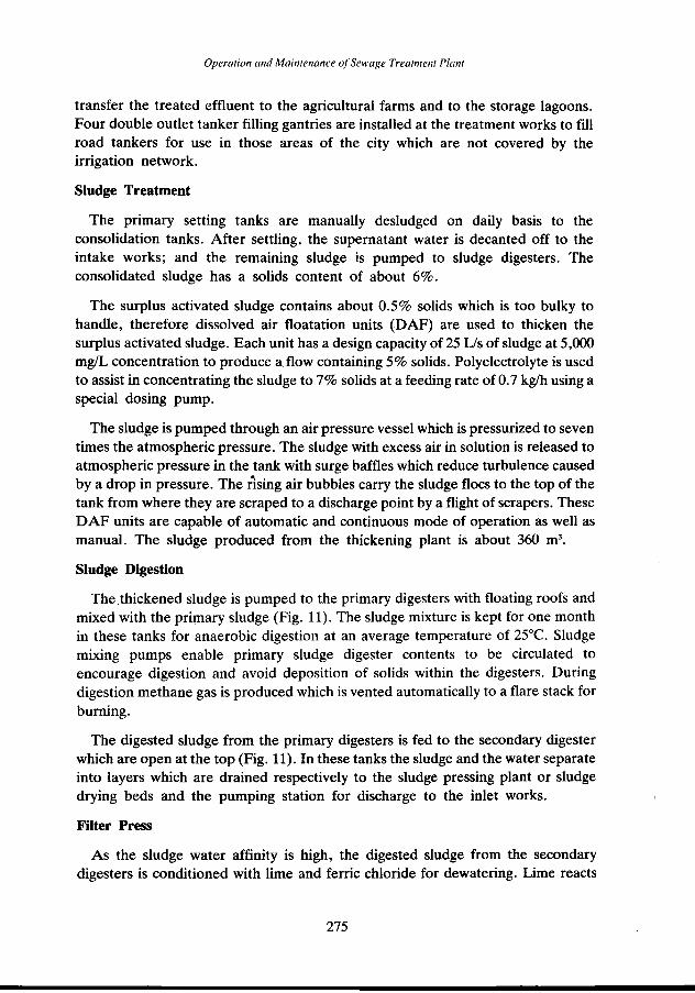
The .thickened sludge is pumped to the primary digesters with floating roofs and mixed with the primary sludge (Fig. 11). The sludge mixture is kept for one month in these tanks for anaerobic digestion at an average temperature of 25°C. Sludge mixing pumps enable primary sludge digester contents to be circulated to encourage digestion and avoid deposition of solids within the digesters. During digestion methane gas is produced which is vented automatically to a flare stack for burning.
The digested sludge from the primary digesters is fed to the secondary digester which are open at the top (Fig. 11). In these tanks the sludge and the water separate into layers which are drained respectively to the sludge pressing plant or sludge drying beds and the pumping station for discharge to the inlet works.
Filter Press
As the sludge water affinity is high, the digested sludge from the secondary digesters is conditioned with lime and ferric chloride for dewatering. Lime reacts
275
Fawzi T. Shadid and Shamim Ahmed
Fig. 11: Prim~ry and secondary digesters
with grease to produce insoluable calcium soaps. The triple positive charge on each ferric iron neutralizes the charge on colloids and permits coagulation. Together these two chemicals flocculate sludge particles sufficiently so that a cake of 30 -35% solids is formed.
The conditioned sludge is pumped into the space between the plates and is pressed in hydraulic plate presses at a pressure of 1250 KN/m2 for 2 hours to form sludge cakes. The liquid is forced out through the filter cloths and plate outlet ports. The filtrate is returned to the inlet works of the treatment plant and the sludge cake, which has a moisture content of about 65 - 70% is transferred to the drying beds.
Sludge Drying Beds
They are used to dewater the digested sludge by the action of natural drainage and evaporation processes. The sludge is placed on the beds in 200-250 mm layer and allowed to dry in the open air for 9 days. After drying the sludge is removed by Doha municipality trucks for use as soil conditioner in farms and landscaping. About 16-20 tons of dry solids with 30% solid content is produced every day.
Safety and Security
Workers safety is paramount (Joint Committee WPCF 1977, Mullick 1987, Qasim 1985). All the workers attend lectures on safety procedures, use of protection gear, handling of sewage and reclaimed water and emergency situations. Workers carry a portable chlorine analyzer while entering Chlorine Room. An alarm system is installed in the chlorine dosing area to warn against any chlorine leakage. Carbon dioxide and hydrogen sulphide portable dete~tion units are used to check the concentration of these gases while working in the wet well or any
276
Operation and Maintenance of Sewage Treatment Plant
enclosed space containing the sewage. Protective masks and outfits with breathing units, hand gloves and footwear are used wherever necessary. Workers are never allowed to enter alone inside the danger zone. They must work in a group of three.
A compound wall runs around the sewage treatment plant and the entrance to the works is controlled by a guard.
Electric Power System
Main electricity (3.3 KV A) is received on site and distributed from five substations to various work areas at 440 volts.
Two separate and independent sources of electric power are installed, one from a sub-station and the other from a diesel generator. The independent sources of power are distributed to separate the transformers in such a way as to minimize common mode failures from affecting both sources. Power distribution reliability features within the plant include service to motor control centers, power transfer, co-ordinated breaker settings or fuse ratings equipment location, and emergency power generator starting.
Automatic controls, instrumentation, alarms, alignment and calibration of equipment are checked and maintained routinely.
Monitoring Water Quality
For assessing the efficiency of the treatment plant the raw sewage and the treated sewage are characterized. Hourly samples from various locations including inlet works and all stages of treatment are collected four days in a week in an automatic sampler and then composited for analysis. All the tests are conducted as per APHA et al, Standard Methods, 1989. The results of the analysis assist the operators in identifying the problems and controlling the processes.
Typical characteristics of the raw and treated sewage are presented in Table 2. The raw sewage is characterized by high dissolved solids, medium BOD, low COD/BOD ratio indicating readily biodegradable organics; and high concentrations of chloride, sulphate and sulfide due to septic sewage. These are the typical characteristics of the sewage in the Gulf region (Ahmed, 1989, Bank, 1991 & Mullick, 1987). Due to the high ground water table, the infiltration of saline groundwater to the sewer network in large, causing an increase in the total dissolved solids. The sewage becomes septic due to (a) the high temperature and humidity, (b) long residence time of sewage in the sewerage network due to low density of urban development; and a higher than normal number of pumping stations. During summer and fall months, strong odor occurs near pumping stations and the sewage treatment plant. There have been public complaints regarding the odor. A pilot plant study is planned in the near future to control the odor by adding ferric nitrate in the sewage system.
Operation and Maintenance of Sewage Treatment Plant
The flow to the plant and the outflow are monitored and recorded (Fig. 12). On an average the flow is about 60,000 m'ld, whereas the design capacity of the plant is 40,000 m3/d indicating that the plant is overloaded. However due to the conservative design and efficient operation and maintenance. the overloading is being handled effectively. The flow to the plant sometimes increases twice the average flow after heavy storms (Ahmed. 1987, 1989).
m3/d
socco r················,······:·· ...... , ... .
70000
60000
50000 ____.__INFLOW
--<>--TO FARM 40000
-.--To LAGOON
30000 ~TO TOWER
10000
g ~ ~ ~ ~ g g ~ ~ ~ ~ g ~ ~ ~ ~ m m ~ ~ ~ ~ ~ ~ ~ ~~·~k·~~i~~~~~i~~·±~~~~~~
Fig. 12: Average flow to various locations
Reliability
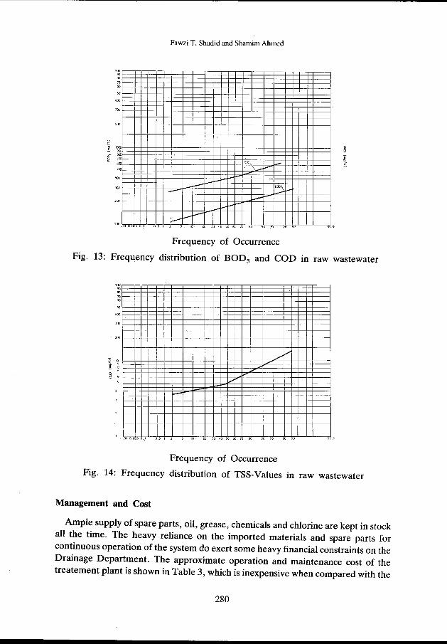
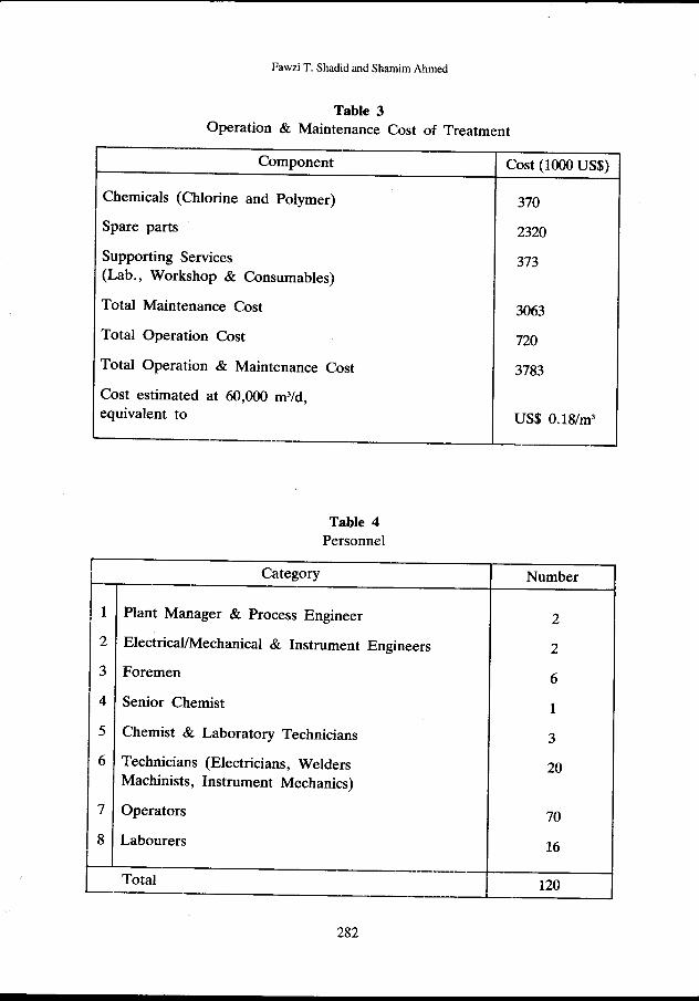
Reliability of a treatment plant must cover performance under normal as well as adverse circumstances (Joint Committee WPCF, 1977). An array of typical BOD, COD and suspended solids concentration data characterizing the raw and treated sewage are presented on frequency distribution plot (Figs. 13, 14, 15, 16). The BOD and suspended solids removal are mostly high which depicts the effluent reliability and shows that the plant is well managed.
The suspended solids, BOD, COD and the coliform organisms in the treated effluent, meet the water quality requirements and guidelines set for the irrigation water used in landscape and agriculture (Ahmed, 1989). The Public Health laboratory of the Ministry of Health, State of Qatar regularly monitors the bacteriological quality of the treated effluent at the plant and in the irrigation network. Total coliform and E-coli bacteria counts have mostly been absent in the samples.
Fig. 13: Frequency distribution of BOD5 and COD in raw wastewater
1 .01 .0050.1
Frequency of Occurrence
Fig. 14: Frequency distribution of TSS-Values in raw wastewater
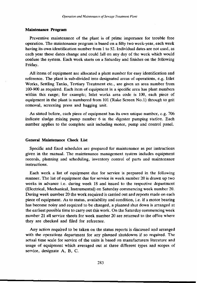
Management and Cost
Ample supply of spare parts, oil, grease, chemicals and chlorine are kept in stock all the time. The heavy reliance on the imported materials and spare parts for continuous operation of the system do exert some heavy financial constraints on the Drainage Department. The approximate operation and maintenance cost of the treatement plant is shown in Table 3, which is inexpensive when compared with the
280
Operation and Maintenance ()(Se\\'age Treatment PlanT
.01 .050 .. 1
Frequency of Occurrence
Fig. 15: Treated effluent reliability in terms of COD
1/
01 .OOSO.) zo 30 40 so 60 70 80 90 95
Frequency of Occurrence
Fig. 16: Treated effluent reliability in terms of TSS-Values
cost of desalinated water which is about QR 5/m3 (US$ 1.4). The cost of electrical power (430 MWhr) is fully subsidized by the State of Qatar.
Personnel
The break down of the personnel employed at the treatment works is given in Table 4.
Operation and Maintenance of Sewage Treatment Plant
Maintenance Program
Preventive maintenance of the plant is of prime imporance for trouble free operation. The maintenance program is based on a fifty two week-year, each week having its own identification number from 1 to 52. Individual dates are not used, as each year these dates change and could fall on any day of the week which would confuse the system. Each week starts on a Saturday and finishes on the following Friday.
All items of equipment are allocated a plant number for easy identification and reference. The plant is sub-divided into designated areas of operations, e.g. Inlet Works, Settling Tanks, Tertiary Treatment etc., are given an area number from 100-900 as required. Each item of equipment in a specific area has plant numbers within this range; for example; Inlet works area code is 100, each piece of equipment in the plant is numbered from 101 (Rake Screen No.1) through to grit removal, screening press and bagging unit. ·
As stated before, each piece of equipment has its own unique number, e.g. 706 indicate sludge mixing pump number 6 in the digester pumping station. Each number applies to the complete unit including motor, pump and control panel.
General Maintenance Check List
Specific and fixed schedules are prepared for maintenance as per instructions given in the manual. The maintenance management system includes equipment records, planning and scheduling, inventory control of parts and maintenance instructions.
Each week a list of equipment due for service is prepared in the following manner. The list of equipment due for service in week number 20 is drawn up two weeks in advance i.e. during week 18 and issued to the respective department (Electrical, Mechanical, Instrumental) on Saturday commencing week number 20. During week number 20 the work required is carried out and reports made on each piece of equipment. As to status, availability and condition, i.e. if a motor bearing has become noisy and required to be changed, a planned shut down is arranged at the earliest possible time to carry out this work. On the Saturday commencing week number 21 all service sheets for week number 20 are returned to the office where they are checked and filed for reference.
Any action required to be taken on the status reports is discussed and arranged with the operations department for any planned shutdowns if so required. The actual time scale for service of the units is based on manufacturers literature and usage of equipment which averaged out at three different types and scopes of service, designate A, B, C.
283
Fawzi T. Shadid and Shamim Ahmed
Service (C) is carried out every 3/9 months. Service (B) is carried out every 6 months. Service (A) is carried out every 12 months.
It can be seen from the designations that Service (C) is included in Service (B) and (B) is included in Service (A). Consequently each year all the pieces of equipment have a comprehensive service cover. Daily and weekly checks are carried out on oiling and greasing as an ongoing operation. Valves and drains are operated and checked from time to time to ensure that these do not get clogged and operate with ease especially during an emergency.
In spite of the preventive maintenance some repairs have to be carried out on an emergency basis, as in case of breakdown. A full-fledged workshop caters to the needs of repair and routine maintenance of the plant equipment.
Apart from the aforesaid maintenance program, accumulations (greasy matter and algae) from the influent and effluent baffles, weirs and scum box in various units are removed regularly. All the inside exposed walls and channels are cleaned by squeegee manually. The tanks are drained annually for the inspection of mechanical parts and the underwater part of the concrete structure. The metal surface are cleaned and painted if necessary. The defective concrete parts areal o repaired.
Summary
Sewage treatment plants in Doha-South is producing water for reuse in landscape irrigation and agricultural farms (Fig. 17). The treated effluent contributes positively to the environment of the country which lies in the arid region. The greeen areas which have developed in the city due to water reuse creates a pleasing effect in an otherwise harsh desert environment.
Fig. 17: Animal fodder farm using treated effluent for irrigation (The depression is due to the tyre of the rotating arm of the sprinkler)
284
Operation and Maintenance of Sewage Treatment Plant
The reclaimed water quality meets the international water quality requirements and guidelines indicating that the plant is well maintained and its operation is reliable.
Financial support from the government shows the commitment of the State of Qatar to maximizing the use of its water resources for the benefit of the people and improving and protecting the environment from pollution hazards.
ACKNOWLEDGEMENT
We wish to acknowledge with thanks the encouragement and support given by Eng. Mohd. M. Al-Hajri, Head Drainage Division and Paul Gillete, Manager Sewage Treatment Works, Doha, during this study.
REFERENCES
1. Ahmad, S., 1987. Field Study of a completely mixed activ'lted sludge process in arid climate . Proceedings of the International Symposium of Environmental Management, Istanbul, p. 23-30.
2. Ahmad, S., 1989. Wastewater Reuse in Landscape and Agricultural Development in Doha, Qatar . Water Science and Technology, Vo. 21, Brighton, p. 421-426.
3. APHA, AWWA and WPCF, 1989. Standard Methods for the Examination of Water and Wastewater, 17th Edition , American Public Health Association, New York.
4. Banks, P.A., 1991. Wastewater Reuse Case Studies in the Middle East Water, Science and Technology, Vol. 23, Kyoto, p. 2141-2148.
5. Escritt, L.B., 1984. Sewerage and Sewage Treatment International Practice, John Wiley and Sons, New York.
6. Joint Committee of the Water Pollution Control Federation and the American Society of Civil Engineers, 1977. Wastewater Treatment Plant Design -Manual of Practice No. 8, Water Pollution Control Federation, Washington, D.C.
7. MuUick, M.A., 1987. Wastewater Treatment Processes in the Middle East The Book Guilds Ltd., Sussex, England.
8. Qasim, S.R., 1985. Wastewater Treatment Plants, Planning, Design and Operation , Holt, Rinehart and Winston, New York, USA.