62
Operation and Safety Manual Keep this manual with the machine at all times. Model(s) DVL & DVSP Series P/N - 3121135 September 27, 2005

Operation and Safety ManualKeep this manual with the machine at all times.
Model(s)DVL &DVSPSeries
P/N - 3121135
September 27, 2005


FOREWORD
FOREWORD
This manual is a very important tool! Keep it with the machine at all times.
The purpose of this manual is to provide owners, users, operators, lessors, and lessees with the precautionsand operating procedures essential for the safe and proper machine operation for its intended purpose.
Due to continuous product improvements, JLG Industries, Inc. reserves the right to make specification changeswithout prior notification. Contact JLG Industries, Inc. for updated information.
Other Publications Available:
Service and Maintenance Manual .......................................................3121136
Illustrated Parts Manual (ANSI/CSA) ...................................................3121137
Illustrated Parts Manual (CE) ...............................................................3121839
3121135 – JLG Lift – a

SAFETY ALERT SYMBOLS AND SAFETY SIGNAL WORDS
SAFETY ALERT SYMBOLS AND SAFETY SIGNAL WORDS
This is the Safety Alert Symbol. It is used to alert you to thepotential personal injury hazards. Obey all safety messagesthat follow this symbol to avoid possible injury or death
INDICATES AN IMMINENTLY HAZARDOUS SITUATION. IF NOTAVOIDED, WILL RESULT IN SERIOUS INJURY OR DEATH. THISDECAL WILL HAVE A RED BACKGROUND.
INDICATES A POTENTIALITY HAZARDOUS SITUATION. IF NOTAVOIDED, COULD RESULT IN SERIOUS INJURY OR DEATH. THISDECAL WILL HAVE AN ORANGE BACKGROUND.
INDICATES A POTENTIALITY HAZARDOUS SITUATION. IF NOTAVOIDED, MAY RESULT IN MINOR OR MODERATE INJURY. IT MAYALSO ALERT AGAINST UNSAFE PRACTICES. THIS DECAL WILLHAVE A YELLOW BACKGROUND.
IMPORTANTINDICATES PROCEDURES ESSENTIAL FOR SAFE OPERATION.THIS DECAL WILL HAVE A GREEN BACKGROUND.
b – JLG Lift – 3121135

SAFETY ALERT SYMBOLS AND SAFETY SIGNAL WORDS
THIS PRODUCT MUST COMPLY WITH ALL SAFETY RELATED BULLETINS. CONTACT JLG INDUSTRIES, INC. OR THE LOCAL AUTHO-RIZED JLG REPRESENTATIVE FOR INFORMATION REGARDING SAFETY-RELATED BULLETINS WHICH MAY HAVE BEEN ISSUED FORTHIS PRODUCT.
JLG INDUSTRIES, INC. SENDS SAFETY RELATED BULLETINS TO THE OWNER OF RECORD OF THIS MACHINE. CONTACT JLG INDUS-TRIES, INC. TO ENSURE THAT THE CURRENT OWNER RECORDS ARE UPDATED AND ACCURATE.
JLG INDUSTRIES, INC. MUST BE NOTIFIED IMMEDIATELY IN ALL INSTANCES WHERE JLG PRODUCTS HAVE BEEN INVOLVED IN ANACCIDENT INVOLVING BODILY INJURY OR DEATH OF PERSONNEL OR WHEN SUBSTANTIAL DAMAGE HAS OCCURRED TO PER-SONAL PROPERTY OR THE JLG PRODUCT.
IMPORTANT
IMPORTANT
FOR :
•Accident Reporting
•Product Safety Publications
•Current Owner Updates
•Questions Regarding Product Safety
•Standards and Regulations Compliance Information
•Questions Regarding Special Product Applications
•Questions Regarding Product Modifications
CONTACT :
Product Safety and Reliability DepartmentJLG Industries, Inc.1 JLG DriveMcConnellsburg, PA 17233
or Your Local JLG Office(See addresses on back cover of manual)
In USA:
Toll Free: 877-JLG-SAFE877-554-7233
Outside USA:
717-485-5161
E-mail: [email protected]
3121135 – JLG Lift – c

REVISION LOG
REVISION LOG
October 1, 2001 – Original Issue of Manual
November 19, 2001 – Manual Revised
December 13, 2001 – Manual Revised
February 22, 2002 – Manual Revised
October 29, 2002 – Manual Revised
January 22, 2003 – Manual Revised
February 18, 2003 – Manual Revised
August 9, 2004 – Manual Revised
May 6, 2005 - Manual Revised
July 25, 2005 – Manual Revised
September 27, 2005 – Manual Revised
d – JLG Lift – 3121135

TABLE OF CONTENTS
TABLE OF CONTENTS
SUBJECT - SECTION, PARAGRAPH PAGE NO.
FOREWORD . . . . . . . . . . . . . . . . . . . . . . . . . . . . . . . . . . . . . . . . . . . . . . . . . . . . . . . . . . . . . . . . . . . . . . . . a
SAFETY ALERT SYMBOLS AND SAFETY SIGNAL WORDS . . . . . . . . . . . . . . . . . . . . . . . . . . . . . . . . . . . b
REVISION LOG . . . . . . . . . . . . . . . . . . . . . . . . . . . . . . . . . . . . . . . . . . . . . . . . . . . . . . . . . . . . . . . . . . . . . . d
SECTION 1 - SAFETY PRECAUTIONS
1.1 GENERAL . . . . . . . . . . . . . . . . . . . . . . . . . . . . . . . . . . . . . . . . . . . . . . . . . . . . . . . . . . . . . . . . . . . . .1-1
1.2 PRE-OPERATION . . . . . . . . . . . . . . . . . . . . . . . . . . . . . . . . . . . . . . . . . . . . . . . . . . . . . . . . . . . . . . .1-1Operator Training And Knowledge . . . . . . . . . . . . . . . . . . . . . . . . . . . . . . . . . . . . . . . . . . . . .1-1Workplace Inspection . . . . . . . . . . . . . . . . . . . . . . . . . . . . . . . . . . . . . . . . . . . . . . . . . . . . . . .1-1Machine Inspection . . . . . . . . . . . . . . . . . . . . . . . . . . . . . . . . . . . . . . . . . . . . . . . . . . . . . . . . .1-1
1.3 OPERATION . . . . . . . . . . . . . . . . . . . . . . . . . . . . . . . . . . . . . . . . . . . . . . . . . . . . . . . . . . . . . . . . . . .1-2General. . . . . . . . . . . . . . . . . . . . . . . . . . . . . . . . . . . . . . . . . . . . . . . . . . . . . . . . . . . . . . . . . . .1-2Trip and Fall Hazard . . . . . . . . . . . . . . . . . . . . . . . . . . . . . . . . . . . . . . . . . . . . . . . . . . . . . . . .1-2Electrocution Hazard . . . . . . . . . . . . . . . . . . . . . . . . . . . . . . . . . . . . . . . . . . . . . . . . . . . . . . . .1-3Tipping Hazard . . . . . . . . . . . . . . . . . . . . . . . . . . . . . . . . . . . . . . . . . . . . . . . . . . . . . . . . . . . .1-3Crushing And Collision Hazard . . . . . . . . . . . . . . . . . . . . . . . . . . . . . . . . . . . . . . . . . . . . . . . .1-4
1.4 TOWING, LIFTING, AND HAULING . . . . . . . . . . . . . . . . . . . . . . . . . . . . . . . . . . . . . . . . . . . . . . . . .1-4
SECTION 2 - PREPARATION AND INSPECTION
2.1 PERSONNEL TRAINING . . . . . . . . . . . . . . . . . . . . . . . . . . . . . . . . . . . . . . . . . . . . . . . . . . . . . . . . .2-1Operator Training. . . . . . . . . . . . . . . . . . . . . . . . . . . . . . . . . . . . . . . . . . . . . . . . . . . . . . . . . . .2-1Training Supervision . . . . . . . . . . . . . . . . . . . . . . . . . . . . . . . . . . . . . . . . . . . . . . . . . . . . . . . .2-1Operator Responsibility . . . . . . . . . . . . . . . . . . . . . . . . . . . . . . . . . . . . . . . . . . . . . . . . . . . . . .2-1
2.2 PREPARATION, INSPECTION, AND MAINTENANCE. . . . . . . . . . . . . . . . . . . . . . . . . . . . . . . . . . .2-2
2.3 PRE-START INSPECTION . . . . . . . . . . . . . . . . . . . . . . . . . . . . . . . . . . . . . . . . . . . . . . . . . . . . . . . .2-3
2.4 DAILY WALK-AROUND INSPECTION . . . . . . . . . . . . . . . . . . . . . . . . . . . . . . . . . . . . . . . . . . . . . . .2-3
2.5 FUNCTION CHECK . . . . . . . . . . . . . . . . . . . . . . . . . . . . . . . . . . . . . . . . . . . . . . . . . . . . . . . . . . . . .2-5
SECTION 3 - MACHINE CONTROLS, INDICATORS AND OPERATION
3.1 GENERAL . . . . . . . . . . . . . . . . . . . . . . . . . . . . . . . . . . . . . . . . . . . . . . . . . . . . . . . . . . . . . . . . . . . . .3-2
3.2 MACHINE DESCRIPTION . . . . . . . . . . . . . . . . . . . . . . . . . . . . . . . . . . . . . . . . . . . . . . . . . . . . . . . .3-2
3.3 MACHINE OPERATION . . . . . . . . . . . . . . . . . . . . . . . . . . . . . . . . . . . . . . . . . . . . . . . . . . . . . . . . . .3-2Getting Started. . . . . . . . . . . . . . . . . . . . . . . . . . . . . . . . . . . . . . . . . . . . . . . . . . . . . . . . . . . . .3-2
3.4 BATTERY CHARGING . . . . . . . . . . . . . . . . . . . . . . . . . . . . . . . . . . . . . . . . . . . . . . . . . . . . . . . . . . .3-2Battery Low Voltage Warning Indicators . . . . . . . . . . . . . . . . . . . . . . . . . . . . . . . . . . . . . . . . .3-3To Charge Batteries. . . . . . . . . . . . . . . . . . . . . . . . . . . . . . . . . . . . . . . . . . . . . . . . . . . . . . . . .3-3Battery Charging Status Indicators . . . . . . . . . . . . . . . . . . . . . . . . . . . . . . . . . . . . . . . . . . . . .3-3
3.5 GROUND CONTROL STATION - OPERATION . . . . . . . . . . . . . . . . . . . . . . . . . . . . . . . . . . . . . . . .3-4Main Power Selector Switch . . . . . . . . . . . . . . . . . . . . . . . . . . . . . . . . . . . . . . . . . . . . . . . . .3-4Emergency Stop/Shut Down Button . . . . . . . . . . . . . . . . . . . . . . . . . . . . . . . . . . . . . . . . . . .3-4 Master Disconnect Switch - (EE Option Only) . . . . . . . . . . . . . . . . . . . . . . . . . . . . . . . . . .3-4Brake Release Button . . . . . . . . . . . . . . . . . . . . . . . . . . . . . . . . . . . . . . . . . . . . . . . . . . . . . . .3-4Platform Up . . . . . . . . . . . . . . . . . . . . . . . . . . . . . . . . . . . . . . . . . . . . . . . . . . . . . . . . . . . . . .3-4Platform Down . . . . . . . . . . . . . . . . . . . . . . . . . . . . . . . . . . . . . . . . . . . . . . . . . . . . . . . . . . . .3-4Manual Descent Control Valve . . . . . . . . . . . . . . . . . . . . . . . . . . . . . . . . . . . . . . . . . . . . . . .3-4Machine Status LCD Display . . . . . . . . . . . . . . . . . . . . . . . . . . . . . . . . . . . . . . . . . . . . . . . . . .3-6LCD Display Fault Conditions . . . . . . . . . . . . . . . . . . . . . . . . . . . . . . . . . . . . . . . . . . . . . . . . .3-6
3121135 – JLG Lift – i

TABLE OF CONTENTS
3.6 GROUND CONTROL STATION - PROGRAMMING. . . . . . . . . . . . . . . . . . . . . . . . . . . . . . . . . . . . .3-8General . . . . . . . . . . . . . . . . . . . . . . . . . . . . . . . . . . . . . . . . . . . . . . . . . . . . . . . . . . . . . . . . . . 3-8Programming Levels . . . . . . . . . . . . . . . . . . . . . . . . . . . . . . . . . . . . . . . . . . . . . . . . . . . . . . . . 3-8Operator Programming Mode . . . . . . . . . . . . . . . . . . . . . . . . . . . . . . . . . . . . . . . . . . . . . . . . . 3-8Activating Programming Mode . . . . . . . . . . . . . . . . . . . . . . . . . . . . . . . . . . . . . . . . . . . . . . . .3-9Entering Password . . . . . . . . . . . . . . . . . . . . . . . . . . . . . . . . . . . . . . . . . . . . . . . . . . . . . . . . 3-9Programming Mode Selection . . . . . . . . . . . . . . . . . . . . . . . . . . . . . . . . . . . . . . . . . . . . . . . 3-9Selecting Programmable Item to Adjust . . . . . . . . . . . . . . . . . . . . . . . . . . . . . . . . . . . . . . .3-10Adjusting Programmable Setting . . . . . . . . . . . . . . . . . . . . . . . . . . . . . . . . . . . . . . . . . . . 3-10
3.7 PLATFORM CONTROL CONSOLE OPERATION -(MACHINES SERIAL NUMBER - 0130007616 TO PRESENT) . . . . . . . . . . . . . . . . . . . . . . . . . . . 3-11
General . . . . . . . . . . . . . . . . . . . . . . . . . . . . . . . . . . . . . . . . . . . . . . . . . . . . . . . . . . . . . . . . . 3-11Platform On/Off Key Switch . . . . . . . . . . . . . . . . . . . . . . . . . . . . . . . . . . . . . . . . . . . . . . . .3-12Platform Emergency Stop/Shut Down Button. . . . . . . . . . . . . . . . . . . . . . . . . . . . . . . . . . . .3-12Platform Control Display Panel . . . . . . . . . . . . . . . . . . . . . . . . . . . . . . . . . . . . . . . . . . . . . . 3-12Drive/Lift Mode Selector Switch . . . . . . . . . . . . . . . . . . . . . . . . . . . . . . . . . . . . . . . . . . . . . 3-13Horn Button . . . . . . . . . . . . . . . . . . . . . . . . . . . . . . . . . . . . . . . . . . . . . . . . . . . . . . . . . . . . .3-13Joystick Function Enable Lever . . . . . . . . . . . . . . . . . . . . . . . . . . . . . . . . . . . . . . . . . . . . . . 3-13Multifunction Joystick Control . . . . . . . . . . . . . . . . . . . . . . . . . . . . . . . . . . . . . . . . . . . . . . . . 3-13Drive Mode . . . . . . . . . . . . . . . . . . . . . . . . . . . . . . . . . . . . . . . . . . . . . . . . . . . . . . . . . . . . . . 3-14Lift Mode . . . . . . . . . . . . . . . . . . . . . . . . . . . . . . . . . . . . . . . . . . . . . . . . . . . . . . . . . . . . . . . 3-14Drive Speed Setting Controls . . . . . . . . . . . . . . . . . . . . . . . . . . . . . . . . . . . . . . . . . . . . . . . .3-14
3.8 PLATFORM CONTROL CONSOLE OPERATION -(MACHINES BEFORE SERIAL NUMBER - 0130007616) . . . . . . . . . . . . . . . . . . . . . . . . . . . . . . . 3-15
At Ground Control Station . . . . . . . . . . . . . . . . . . . . . . . . . . . . . . . . . . . . . . . . . . . . . . . . . . 3-15Emergency Stop/Shut-Down Button . . . . . . . . . . . . . . . . . . . . . . . . . . . . . . . . . . . . . . . . . . 3-15Battery Charge/Fault Code LED Indicator . . . . . . . . . . . . . . . . . . . . . . . . . . . . . . . . . . . . . .3-16Driving Machine . . . . . . . . . . . . . . . . . . . . . . . . . . . . . . . . . . . . . . . . . . . . . . . . . . . . . . . . . . .3-16Adjusting Maximum Drive Speed Control . . . . . . . . . . . . . . . . . . . . . . . . . . . . . . . . . . . . . . .3-17Elevating/Lowering the Platform . . . . . . . . . . . . . . . . . . . . . . . . . . . . . . . . . . . . . . . . . . . . . . 3-17
3.9 PARKING MACHINE. . . . . . . . . . . . . . . . . . . . . . . . . . . . . . . . . . . . . . . . . . . . . . . . . . . . . . . . . . . .3-17
3.10 PROGAMMABLE SECURITY LOCK (PSL™) (DVL/DVSP - OPTION) . . . . . . . . . . . . . . . . . . . . . . 3-18PSL™ Box and Ground Control Locations . . . . . . . . . . . . . . . . . . . . . . . . . . . . . . . . . . . . . . 3-18Machine Power Up using the PSL™ . . . . . . . . . . . . . . . . . . . . . . . . . . . . . . . . . . . . . . . . . . . 3-18Machine Power Down . . . . . . . . . . . . . . . . . . . . . . . . . . . . . . . . . . . . . . . . . . . . . . . . . . . . . . 3-18Changing the Operator’s Code . . . . . . . . . . . . . . . . . . . . . . . . . . . . . . . . . . . . . . . . . . . . . . . 3-18
3.11 PLATFORM CONFIGURATIONS . . . . . . . . . . . . . . . . . . . . . . . . . . . . . . . . . . . . . . . . . . . . . . . . . .3-19StockPicking Platform Operation . . . . . . . . . . . . . . . . . . . . . . . . . . . . . . . . . . . . . . . . . . . . . 3-20
3.12 FALL PROTECTION - LANYARD ATTACHMENT. . . . . . . . . . . . . . . . . . . . . . . . . . . . . . . . . . . . . .3-21
3.13 QUICK-CHANGE PLATFORM MOUNTING . . . . . . . . . . . . . . . . . . . . . . . . . . . . . . . . . . . . . . . . . . 3-21Platform Removal. . . . . . . . . . . . . . . . . . . . . . . . . . . . . . . . . . . . . . . . . . . . . . . . . . . . . . . . . . 3-21Platform Installation . . . . . . . . . . . . . . . . . . . . . . . . . . . . . . . . . . . . . . . . . . . . . . . . . . . . . . . . 3-21
3.14 OBSTRUCTION SENSING SYSTEM (DVSP - OPTION) . . . . . . . . . . . . . . . . . . . . . . . . . . . . . . . . 3-22System Description . . . . . . . . . . . . . . . . . . . . . . . . . . . . . . . . . . . . . . . . . . . . . . . . . . . . . . . . 3-22Operation . . . . . . . . . . . . . . . . . . . . . . . . . . . . . . . . . . . . . . . . . . . . . . . . . . . . . . . . . . . . . . . . 3-22OSS Pre-Start Inspection. . . . . . . . . . . . . . . . . . . . . . . . . . . . . . . . . . . . . . . . . . . . . . . . . . . . 3-22
3.15 TRANSPORTING, LIFTING AND TIE DOWN PROCEDURES . . . . . . . . . . . . . . . . . . . . . . . . . . . . 3-23General . . . . . . . . . . . . . . . . . . . . . . . . . . . . . . . . . . . . . . . . . . . . . . . . . . . . . . . . . . . . . . . . . 3-23Truck Transport . . . . . . . . . . . . . . . . . . . . . . . . . . . . . . . . . . . . . . . . . . . . . . . . . . . . . . . . . . .3-23Machine Tie-Down . . . . . . . . . . . . . . . . . . . . . . . . . . . . . . . . . . . . . . . . . . . . . . . . . . . . . . . . . 3-24Crane Hook Accessory (DVL Option). . . . . . . . . . . . . . . . . . . . . . . . . . . . . . . . . . . . . . . . . . 3-24Fork-Lift Truck Transport . . . . . . . . . . . . . . . . . . . . . . . . . . . . . . . . . . . . . . . . . . . . . . . . . . . . 3-24
3.16 RUG CARRIER ACCESSORY (DVSP - OPTION) . . . . . . . . . . . . . . . . . . . . . . . . . . . . . . . . . . . . . .3-25General . . . . . . . . . . . . . . . . . . . . . . . . . . . . . . . . . . . . . . . . . . . . . . . . . . . . . . . . . . . . . . . . . 3-25
ii – JLG Lift – 3121135

TABLE OF CONTENTS
Pre-Start Inspection . . . . . . . . . . . . . . . . . . . . . . . . . . . . . . . . . . . . . . . . . . . . . . . . . . . . . . . .3-25Hanging a Rug using the Rug Carrier Accessory Arms . . . . . . . . . . . . . . . . . . . . . . . . . . . .3-25Removing a Rug using Rug Carrier Accessory Arms . . . . . . . . . . . . . . . . . . . . . . . . . . . . . .3-26
3.17 STOCK-PICKER HANGER ACCESSORY. . . . . . . . . . . . . . . . . . . . . . . . . . . . . . . . . . . . . . . . . . . .3-27Pre-Start Inspection . . . . . . . . . . . . . . . . . . . . . . . . . . . . . . . . . . . . . . . . . . . . . . . . . . . . . . . .3-27Loading and Transporting an Item using the Hanger Accessory . . . . . . . . . . . . . . . . . . . . .3-27
SECTION 4 - EMERGENCY PROCEDURES
4.1 GENERAL INFORMATION . . . . . . . . . . . . . . . . . . . . . . . . . . . . . . . . . . . . . . . . . . . . . . . . . . . . . . . .4-1
4.2 EMERGENCY OPERATION . . . . . . . . . . . . . . . . . . . . . . . . . . . . . . . . . . . . . . . . . . . . . . . . . . . . . . .4-1Operator Unable to Control Machine . . . . . . . . . . . . . . . . . . . . . . . . . . . . . . . . . . . . . . . . . . .4-1Platform Caught Overhead . . . . . . . . . . . . . . . . . . . . . . . . . . . . . . . . . . . . . . . . . . . . . . . . . . .4-1
4.3 INCIDENT NOTIFICATION . . . . . . . . . . . . . . . . . . . . . . . . . . . . . . . . . . . . . . . . . . . . . . . . . . . . . . . .4-1
SECTION 5 - GENERAL SPECIFICATIONS AND OPERATOR MAINTENANCE
5.1 INTRODUCTION. . . . . . . . . . . . . . . . . . . . . . . . . . . . . . . . . . . . . . . . . . . . . . . . . . . . . . . . . . . . . . . .5-1
5.2 GENERAL SPECIFICATIONS. . . . . . . . . . . . . . . . . . . . . . . . . . . . . . . . . . . . . . . . . . . . . . . . . . . . . .5-1Machine Specifications . . . . . . . . . . . . . . . . . . . . . . . . . . . . . . . . . . . . . . . . . . . . . . . . . . . .5-1Electrical Specifications . . . . . . . . . . . . . . . . . . . . . . . . . . . . . . . . . . . . . . . . . . . . . . . . . . .5-2Platform Data . . . . . . . . . . . . . . . . . . . . . . . . . . . . . . . . . . . . . . . . . . . . . . . . . . . . . . . . . . .5-2Machine Component Weights . . . . . . . . . . . . . . . . . . . . . . . . . . . . . . . . . . . . . . . . . . . . . .5-2Serial Number Locations . . . . . . . . . . . . . . . . . . . . . . . . . . . . . . . . . . . . . . . . . . . . . . . . . . . . .5-2
5.3 OPERATOR MAINTENANCE . . . . . . . . . . . . . . . . . . . . . . . . . . . . . . . . . . . . . . . . . . . . . . . . . . . . . .5-3Lubrication . . . . . . . . . . . . . . . . . . . . . . . . . . . . . . . . . . . . . . . . . . . . . . . . . . . . . . . . . . . . . . . .5-3
SECTION 6 - INSPECTION AND REPAIR LOG
LIST OF FIGURES
FIGURE NO. TITLE PAGE NO.
2-1. Daily Walk-Around Inspection for DVL/DVSP Machines. . . . . . . . . . . . . . . . . . . . . . . . . . . . . . . . .2-43-1. Battery Charger Location. . . . . . . . . . . . . . . . . . . . . . . . . . . . . . . . . . . . . . . . . . . . . . . . . . . . . . . . .3-23-2. Ground Control Station. (Machine Rear View) . . . . . . . . . . . . . . . . . . . . . . . . . . . . . . . . . . . . . . . .3-53-3. Platform Control Console (Machines Serial Number - 0130007616 to Present) . . . . . . . . . . . . . .3-113-4. Platform Control Display Panel. . . . . . . . . . . . . . . . . . . . . . . . . . . . . . . . . . . . . . . . . . . . . . . . . . . .3-123-5. Platform Control Console (Machines Before Serial Number - 0130007616) . . . . . . . . . . . . . . . . .3-153-6. PSL™ Switch & Ground Control Station Locations - At Rear of Machine. . . . . . . . . . . . . . . . . . . .3-183-7. PSL™ Switch Controls & Indicators. . . . . . . . . . . . . . . . . . . . . . . . . . . . . . . . . . . . . . . . . . . . . . . . .3-183-8. OSS Transducer Sensor Array Location. . . . . . . . . . . . . . . . . . . . . . . . . . . . . . . . . . . . . . . . . . . . .3-223-9. OSS - Pre-Start Inspection of Operation. . . . . . . . . . . . . . . . . . . . . . . . . . . . . . . . . . . . . . . . . . . . .3-233-10. Crane Hook Accessory . . . . . . . . . . . . . . . . . . . . . . . . . . . . . . . . . . . . . . . . . . . . . . . . . . . . . . . . . .3-243-11. Forklift Truck Lifting Pockets and Machine Tie Down Bar Locations. . . . . . . . . . . . . . . . . . . . . . .3-243-12. DVL Series Decal Installation Chart - (See Table 3-5 for Specification) . . . . . . . . . . . . . . . . . . . . .3-283-13. DVSP Decal Installation Chart - (See Table 3-6. for Specification) . . . . . . . . . . . . . . . . . . . . . . . .3-30
3121135 – JLG Lift – iii

TABLE OF CONTENTS
LIST OF TABLES
TABLE NO. TITLE PAGE NO.
1-1 Minimum Safe Approach Distance (M.S.A.D.) . . . . . . . . . . . . . . . . . . . . . . . . . . . . . . . . . . . . . . . .1-32-1 Inspection and Maintenance Table. . . . . . . . . . . . . . . . . . . . . . . . . . . . . . . . . . . . . . . . . . . . . . . . .2-23-1 DVL And DVSP - Machine Operating Specifications . . . . . . . . . . . . . . . . . . . . . . . . . . . . . . . . . . .3-13-2 Battery Low Voltage Warning Indicators. . . . . . . . . . . . . . . . . . . . . . . . . . . . . . . . . . . . . . . . . . . . .3-33-3 LCD Display - Operating Fault Conditions. . . . . . . . . . . . . . . . . . . . . . . . . . . . . . . . . . . . . . . . . . .3-73-4 DVL/DVSP Ground Control Station - Level 3 - Programmable Settings and Factory Presets. . . .3-83-5 DVL Series - Decal Installation Chart . . . . . . . . . . . . . . . . . . . . . . . . . . . . . . . . . . . . . . . . . . . . . . .3-293-6 DVSP Decal Installation Chart. . . . . . . . . . . . . . . . . . . . . . . . . . . . . . . . . . . . . . . . . . . . . . . . . . . . .3-315-1 Lubrication Specifications . . . . . . . . . . . . . . . . . . . . . . . . . . . . . . . . . . . . . . . . . . . . . . . . . . . . . . . .5-35-2 Lubrication Intervals for Various Components . . . . . . . . . . . . . . . . . . . . . . . . . . . . . . . . . . . . . . . .5-46-1 Inspection and Repair Log . . . . . . . . . . . . . . . . . . . . . . . . . . . . . . . . . . . . . . . . . . . . . . . . . . . . . . .6-1
iv – JLG Lift – 3121135

SECTION 1 - SAFETY PRECAUTIONS
SECTION 1. SAFETY PRECAUTIONS
1.1 GENERALThis section outlines the necessary precautions for properand safe machine usage and maintenance. For propermachine use, it is mandatory that a daily routine is estab-lished based on the content of this manual. A mainte-nance program, using the information provided in thismanual and the Service and Maintenance Manual, mustalso be established by a qualified person and must be fol-lowed to ensure that the machine is safe to operate.
The owner/user/operator/lessor/lessee of the machineshould not accept operating responsibility until this man-ual has been read, training is accomplished, and opera-tion of the machine has been completed under thesupervision of an experienced and qualified operator.
If there are any questions with regard to safety, training,inspection, maintenance, application, and operation,please contact JLG Industries, Inc. (“JLG”).
FAILURE TO COMPLY WITH THE SAFETY PRECAUTIONS LISTEDIN THIS MANUAL COULD RESULT IN MACHINE DAMAGE, PROP-ERTY DAMAGE, PERSONAL INJURY OR DEATH.
1.2 PRE-OPERATION
Operator Training And Knowledge
• Read and understand this manual before operating themachine.
• Do not operate this machine until complete training isperformed by authorized persons.
• Only authorized and qualified personnel can operatethe machine.
• Read, understand, and obey all DANGERS, WARN-INGS, CAUTIONS, and operating instructions on themachine and in this manual.
• Use the machine in a manner which is within the scopeof its intended application set by JLG.
• All operating personnel must be familiar with the emer-gency controls and emergency operation of themachine as specified in this manual.
• Read, understand, and obey all applicable employer,local, and governmental regulations as they pertain tooperation of the machine.
Workplace Inspection
• The operator is to take safety measures to avoid all haz-ards in the work area prior to machine operation.
• Do not operate or raise the platform while on trucks,trailers, railway cars, floating vessels, scaffolds or otherequipment unless approved in writing by JLG.
• This machine can be operated in temperatures of 0° Fto 104° F (-20° C to 40° C). Consult JLG for operationoutside this range.
Machine Inspection
• Before machine operation, perform inspections andfunctional checks. Refer to Section 2 of this manual fordetailed instructions.
• Do not operate this machine until it has been servicedand maintained according to requirements specified inthe Service and Maintenance Manual.
3121135 – JLG Lift – 1-1

SECTION 1 - SAFETY PRECAUTIONS
• Ensure all safety devices are operating properly. Modifi-cation of these devices is a safety violation.
MODIFICATION OR ALTERATION OF AN AERIAL WORK PLAT-FORM SHALL BE MADE ONLY WITH PRIOR WRITTEN PERMIS-SION FROM THE MANUFACTURER
• Do not operate any machine on which the safety orinstruction placards or decals are missing or illegible.
• Avoid any build up of debris on platform floor. Keepmud, oil, grease, and other slippery substances fromfootwear and platform floor.
1.3 OPERATION
General
• Do not use the machine for any purpose other thanpositioning personnel, their tools and equipment, or forhand stock picking.
• Never operate a machine that is not working properly. Ifa malfunction occurs, shut down the machine.
• Never slam a control switch or lever through neutral toan opposite direction. Always return switch to neutraland stop before moving the switch to the next function.Operate controls with slow and even pressure.
• Do not allow personnel to tamper with or operate themachine from the ground with personnel in the plat-form, except in an emergency.
• Do not carry materials directly on platform railing unlessapproved by JLG.
• Always ensure that power tools are properly stowedand never left hanging by their cord from the platformwork area.
• Fully lower mast assembly and shut off all power beforeleaving machine.
• When performing welding operations at elevation, pre-cautions must be taken to protect all machine compo-nents from contact with weld splatter or molten metal.
• Battery fluid is highly corrosive. Avoid contact with skinand clothing at all times.
• Charge batteries on in a well ventilated area.
Trip and Fall Hazard
• JLG Industries, Inc. recommends that the operator inthe platform wear a full body harness with a lanyardattached to an authorized lanyard anchorage point. Forfurther information regarding fall protection require-ments on JLG products, contact JLG Industries, Inc.
• Before operating the machine, make sure all railing andgates are fastened in their proper position.
• Keep both feet firmly positioned on the platform floor atall times. Never use ladders, boxes, steps, planks, orsimilar items on platform to provide additional reach.
• Never use the mast assembly to enter or leave the plat-form.
• Use extreme caution when entering or leaving platform.Ensure that the mast assembly is fully lowered. Facethe machine when entering or leaving the platform.Always maintain “three point contact” with the machine,using two hands and one foot or two feet and one handat all times during entry and exit.
• Platform-to-structure transfers at elevated positions arediscouraged. Where transfer is necessary, enter/exitthrough the gate only with the platform within 1 foot(0.3m) of a safe and secure structure. 100% tie-off isalso required in this situation utilizing two lanyards.One lanyard must be attached to the platform with thesecond lanyard attached to the structure. The lanyardconnected to the platform must not be disconnecteduntil such time the transfer to the structure is safe andcomplete.
1-2 – JLG Lift – 3121135

SECTION 1 - SAFETY PRECAUTIONS
Electrocution Hazard
Maintain a clearance of at least 10 ft (3m) between anypart of the machine and its occupants, their tools, andtheir equipment from any electrical line or apparatus car-rying up to 50,000 volts. One foot (0.3m) additional clear-ance is required for every additional 30,000 volts or less.
The minimum safe approach distance may be reduced ifinsulating barriers are installed to prevent contact, and ifthe barriers are rated for the voltage of the line beingguarded. These barriers shall not be part of (or attachedto) the machine. The minimum safe approach distanceshall be reduced to a distance within the designed work-ing dimensions of the insulating barrier. This determina-tion shall be made by a qualified person in accordancewith employer, local, or governmental requirements forwork practices near energized equipment.
Tipping Hazard
• The user should be familiar with the surface before driv-ing. Do not exceed the allowable sideslope and gradewhile driving.
• Do not elevate platform or drive with platform elevatedwhile on a slope, or on an uneven or soft surface.
• Before driving on floors, bridges, trucks, and other sur-faces, check allowable capacity of the surfaces.
• Never exceed the maximum platform capacity. Distrib-ute loads evenly on platform floor.
• Keep the chassis of the machine a minimum of 2 ft.(0.6m) from holes, bumps, drop-offs, obstructions,debris, concealed holes, and other potential hazards atthe ground level.
• Never attempt to use the machine as a crane. Do nottie-off machine to any adjacent structure.
• Do not increase the platform size with unauthorizeddeck extensions or attachments, increasing the areaexposed to wind will decrease stability.
• If mast assembly or platform is caught so that one ormore wheels are off the ground, the operator must beremoved before attempting to free the machine. Usecranes, forklift trucks, or other appropriate equipment tostabilize machine and remove personnel.
Table 1-1. Minimum Safe Approach Distance (M.S.A.D.)
VOLTAGE RANGE(PHASE TO PHASE)
MINIMUM SAFE APPROACH DISTANCE - Feet (m)
0-50KV 10 (3)
Over 50KV to 200KV 15 (5)
Over 200KV to 350KV 20 (6)
Over 350KV to 500KV 25 (8)
Over 500KV to 750KV 35 (11)
Over 750KV to 1000KV 45 (14)
NOTE: This Minimum Safe Approach Distance shall apply
except where employer, local, or governmental regu-
lations are more stringent.
3121135 – JLG Lift – 1-3

SECTION 1 - SAFETY PRECAUTIONS
Crushing And Collision Hazard
• Personal protection equipment must be worn by alloperating and ground personnel.
• Check work area clearances above, on sides, and bot-tom of platform while driving and lifting or lowering plat-form.
• During operation, keep all body parts inside platformrailing.
• Always post a lookout when driving in areas wherevision is obstructed.
• Keep non-operating personnel at least 6 ft. (1.8m) awayfrom machine during all driving operations.
• Limit travel speed according to conditions of groundsurface, congestion, visibility, slope, location of person-nel, and other factors causing hazards of collision orinjury to personnel.
• Be aware of stopping distances in all drive speeds.
• Do not drive at high speeds in restricted or close quar-ters or when driving in reverse.
• Exercise extreme caution at all times to prevent obsta-cles from striking or interfering with operating controlsand persons in the platform.
• Ensure that operators of other overhead and floor levelmachines are aware of the aerial work platform’s pres-ence. Disconnect power to overhead cranes.
• Warn personnel not to work, stand, or walk under araised platform. Position barricades on floor as neces-sary.
1.4 TOWING, LIFTING, AND HAULING
• Never allow personnel in platform while towing, lifting,or hauling.
• This machine should not be towed, except in the eventof emergency, malfunction, power failure, or loading/unloading. Refer to the Emergency Procedures Sectionof this manual for emergency towing procedures.
• Ensure platform is fully retracted and completely emptyof tools prior to towing, lifting or hauling.
• Do not assist a stuck or disabled machine by pushingor pulling except by pulling at the chassis tie-downbars.
• When lifting machine with a forklift, position forks only atdesignated areas of the machine. Lift with a forklift ofadequate capacity.
• Refer to the Machine Operation section of this manualfor lifting information.
1-4 – JLG Lift – 3121135

SECTION 2 - PREPARATION AND INSPECTION
SECTION 2. PREPARATION AND INSPECTION
2.1 PERSONNEL TRAININGThe aerial platform is a personnel handling device; so it isnecessary that it be operated and maintained only bytrained personnel.
Persons under the influence of drugs or alcohol or whoare subject to seizures, dizziness or loss of physical con-trol must not operate this machine.
Operator Training
Operator training must cover:
1. Use and limitations of the controls in the platformand at the ground, emergency controls and safetysystems.
2. Control labels, instructions, and warnings on themachine.
3. Rules of the employer and government regulations.
4. Use of approved fall protection device.
5. Enough knowledge of the mechanical operation ofthe machine to recognize a malfunction.
6. The safest means to operate the machine whereoverhead obstructions, other moving equipment,and obstacles, depressions, holes, drop-offs arepresent.
7. Means to avoid the hazards of unprotected electricalconductors.
8. Specific job requirements or machine application.
Training Supervision
Training must be done under the supervision of a qualifiedperson in an open area free of obstructions until thetrainee has developed the ability to safely control andoperate the machine.
Operator Responsibility
The operator must be instructed that he/she has theresponsibility and authority to shut down the machine incase of a malfunction or other unsafe condition of eitherthe machine or the job site.
NOTE: The Manufacturer or Distributor will provide qualifiedpeople for training assistance with the first unit(s)delivered and from that time forward as requested bythe user or his/her personnel.
3121135 – JLG Lift – 2-1

SECTION 2 - PREPARATION AND INSPECTION
2.2 PREPARATION, INSPECTION, AND MAINTENANCE
The following table covers the periodic machine inspec-tions and maintenance recommended by JLG Industries,Inc. Consult local regulations for further requirements foraerial work platforms. The frequency of inspections andmaintenance must be increased as necessary when themachine is used in a harsh or hostile environment, if themachine is used with increased frequency, or if themachine is used in a severe manner.
IMPORTANTJLG IND USTRIES, INC . RECOGNIZES A QUALIFIED JLGMECHANIC AS A PERSON WHO HAS SUCCESSFULLY COM-PLETED THE JLG SERVICE TRAINING SCHOOL FOR THE SPE-CIFIC JLG PRODUCT MODEL.
Table 2-1. Inspection and Maintenance Table
TYPE FREQUENCYPRIMARY
RESPONSIBILITYSERVICE
QUALIFICATIONREFERENCE
Pre-StartInspection
Before using each day; or whenever there’s an Operator change.
User or Operator User or Operator Operator and Safety Manual
Pre-Delivery Inspection(See Note)
Before each sale, lease, or rental delivery. Owner, Dealer, or User Qualified JLG Mechanic
Service and Maintenance Manual and applicable JLG inspection form
FrequentInspection
In service for 3 months or 150 hours, whichever comes first; or;Out of service for a period of more than 3 months; orPurchased used.
Owner, Dealer, or User Qualified JLG Mechanic
Service and Maintenance Manual and applicable JLG inspection form
Annual Machine Inspection
Annually, no later than 13 months from the date of prior inspection.
Owner, Dealer, or User Qualified JLG Mechanic
Service and Maintenance Manual and applicable JLG inspection form
PreventativeMaintenance
At intervals as specified in the Service and Mainte-nance Manual.
Owner, Dealer, or User Qualified JLG Mechanic
Service and Maintenance Manual
NOTE: Inspection forms are available from JLG. Use the Service and Maintenance Manual to perform inspections.
2-2 – JLG Lift – 3121135
SECTION 2 - PREPARATION AND INSPECTION
2.3 PRE-START INSPECTIONThe Pre-Start Inspection should include each of the follow-ing:
1. Cleanliness – Check all surfaces for leakage (oil,fuel, or battery fluid) or foreign objects. Report anyleakage to the proper maintenance personnel.
2. Decals and Placards – Check all for cleanlinessand legibility. Make sure no decals or placards aremissing. Make sure all illegible decals and placardsare cleaned or replaced. (Reference "Decal Installa-tions" in Section 3).
3. Operators and Safety Manuals – Make sure a copyof the Operator and Safety Manual, EMI Safety Man-ual (Domestic only), and ANSI Manual of Responsi-bilities (Domestic only) is enclosed in the weatherresistant storage container.
4. Daily Walk-Around Inspection – (See Section 2.4)
5. Battery – Charge as required.
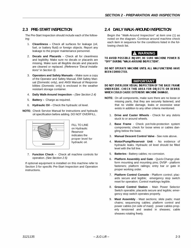
6. Hydraulic Oil – Check the hydraulic oil level.
NOTE: Check Service Manual for instructions and hydraulicoil specification before adding. DO NOT OVERFILL.
7. Function Check – Check all machine controls foroperation. (See Section 2.5)
If optional equipment is installed on this machine refer toSection 3 for specific Pre-Start Inspection and Operationinstructions.
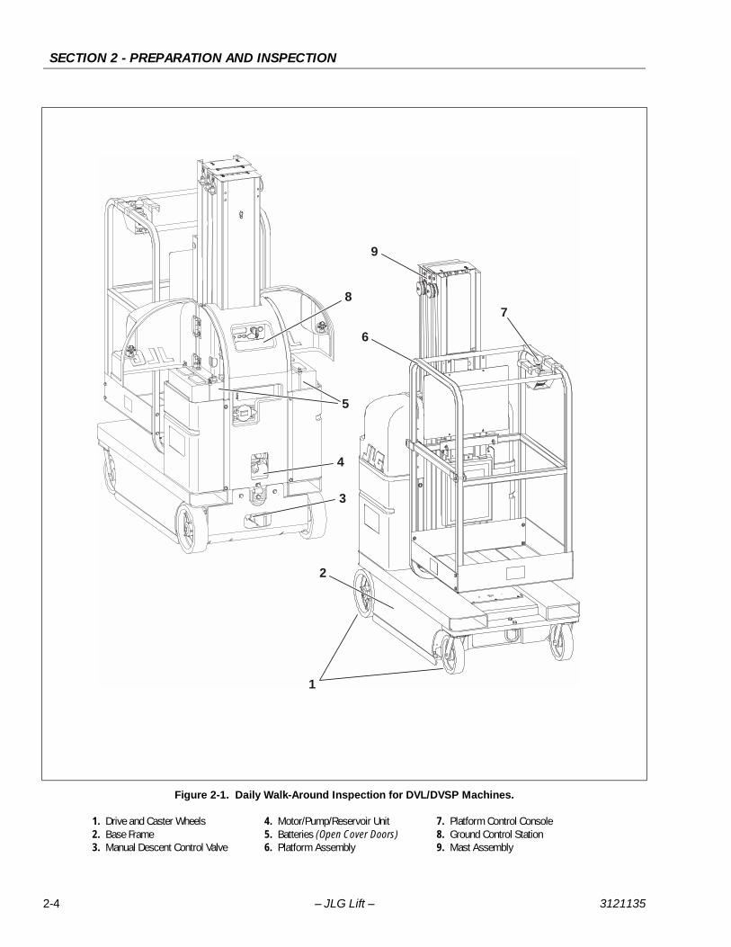
2.4 DAILY WALK-AROUND INSPECTIONBegin the “Walk-Around Inspection” at item one (1) asnoted on the diagram. Continue around machine checkeach item in sequence for the conditions listed in the fol-lowing check list.
TO AVOID POSSIBLE INJURY, BE SURE MACHINE POWER IS“OFF” DURING “WALK-AROUND INSPECTION”.
DO NOT OPERATE MACHINE UNTIL ALL MALFUNCTIONS HAVEBEEN CORRECTED.
IMPORTANTDO NOT OVERLOOK VISUAL INSPECTION OF THE BASE FRAMEUNDERSIDE. CHECK THIS AREA FOR OBJECTS OR DEBRISWHICH COULD CAUSE EXTENSIVE MACHINE DAMAGE.
NOTE: On all components, make sure there are no loose ormissing parts, that they are securely fastened, andthat no visible damage, leaks or excessive wearexists in addition to any other criteria mentioned.
1. Drive and Caster Wheels - Check for any debrisstuck to or around wheels.
2. Base Frame - Check pot-hole-protection systemcomponents; check for loose wires or cables dan-gling below the base.
3. Manual Descent Control Valve - See note above.
4. Motor/Pump/Reservoir Unit - No evidence ofhydraulic leaks. Hydraulic oil level should be filledlevel with the full line.
5. Batteries - Battery cables; no corrosion.
6. Platform Assembly and Gate - Quick-Change plat-form mounting and mounting pins; DVSP - platformfasteners; platform railings; entry bar or gate inproper working order.
7. Platform Control Console - Platform control; plac-ards secure and legible; emergency stop switchreset for operation; Control markings legible.
8. Ground Control Station - Main Power SelectorSwitch operable; placards secure and legible; emer-gency stop switch operates properly.
9. Mast Assembly - Mast sections; slide pads; mastchains; sequencing cables; platform control andpower cables (on side of mast); power cables prop-erly tensioned and seated in sheaves; cablesheaves rotating freely.
FILL TO LINEon HydraulicReservoirindicates theproper level forhydraulic oil.
3121135 – JLG Lift – 2-3
SECTION 2 - PREPARATION AND INSPECTION
Figure 2-1. Daily Walk-Around Inspection for DVL/DVSP Machines.
1. Drive and Caster Wheels 4. Motor/Pump/Reservoir Unit 7. Platform Control Console2. Base Frame 5. Batteries (Open Cover Doors) 8. Ground Control Station3. Manual Descent Control Valve 6. Platform Assembly 9. Mast Assembly
1
2
5
4
8
3
9
6
7
2-4 – JLG Lift – 3121135

SECTION 2 - PREPARATION AND INSPECTION
2.5 FUNCTION CHECKOnce the “Walk-Around” Inspection is complete, performa function check of all systems in an area free of overheadand ground level obstructions. Refer to Section 3 for morespecific operating instructions.
IF THE MACHINE DOES NOT OPERATE PROPERLY, TURN OFFTHE MACHINE IMMEDIATELY! REPORT THE PROBLEM TO THEPROPER MAINTENANCE PERSONNEL. DO NOT OPERATE THEMACHINE UNTIL IT IS DECLARED SAFE FOR OPERATION.
Perform a Function Check as follows:
1. From the ground controls with no load in the plat-form:
a. Operate ground control functions, platform liftup and lift down.
NOTE: Ensure Pot-Hole-Protection device is fully engaged(both bars down) when the platform is elevated.
b. Ensure that all machine functions are disabledwhen the Emergency Stop Button is activated.
c. Check Manual Descent Control valve is operat-ing properly.
2. From the platform control console:
a. Ensure that the control console is properlymounted and secure.
b. Raise and lower platform 2 ft. to 3 ft. (.61m to .92m) several times. Check for smooth elevationand lowering of platform.
c. Operate all functions and check all limit and cut-out switches.
d. Ensure that all machine functions are disabledwhen the Emergency Stop Button is activated.
3. With platform in the transport (stowed) position:
a. Drive the machine on a grade, not to exceed therated grade ability, and stop to ensure thebrakes hold.
b. Check the 1.5 degree tilt sensor alarm to ensureproper operation.
3121135 – JLG Lift – 2-5

SECTION 2 - PREPARATION AND INSPECTION
This page intentionally left blank.
2-6 – JLG Lift – 3121135

SECTION 3 - MACHINE CONTROLS, INDICATORS AND OPERATION
SECTION 3. MACHINE CONTROLS, INDICATORS AND OPERATION
Table 3-1. DVL And DVSP - Machine Operating Specifications
15DVL 20DVL 15DVSP 20DVSP
Maximum Occupants: 1
Maximum Work Load (Capacity):(DVL-Std. Platform / DVSP - Stockpicker Platform)
500 lb.(230 kg)
350 lb.(160 kg)
500 lb.(230 kg)
400 lb.(180 kg)
Maximum Travel Grade (Gradeability):(Platform STOWED ONLY)
20%
Maximum Travel Grade (Side Slope):(Platform STOWED ONLY)
5°
Machine Height (Platform Stowed) 78 in. (198cm)
Maximum Vertical Platform Height: 15 ft. (4.57 m) 19.5 ft. (5.94 m) 15 ft. (4.57 m) 19.5 ft. (5.94 m)
Maximum Wheel Load (Per Wheel): 800 lb. (360 kg)
Maximum Drive Speeds (Operator Variable): 0.5 - 2 mph (0.8 - 3.2 kph)
Max. Platform Speeds (w/Max. Load): Plat-form Up:
20 sec. 22.5 sec. 20 sec. 22.5 sec.
Platform Down: 15 - 21 sec. 21 - 26 sec. 15 - 21 sec. 21 - 26 sec.
Gross Machine Weight(Standard Equipment/Platform Empty):
2,105 lb.(955 kg)
2,105 lb.(955 kg)
2,150 lb.(975 kg)
2,150 lb.(975kg)
3121135 – JLG Lift – 3-1

SECTION 3 - MACHINE CONTROLS, INDICATORS AND OPERATION
3.1 GENERAL
IMPORTANTTHE M ANUFACTU RER HAS NO DIRECT CONTROL OVERMACHINE APPLICATION AND OPERATION. THE USER ANDOPERATOR ARE RESPONSIBLE FOR CONFORMING WITH GOODSAFETY PRACTICES.
This section provides the necessary information neededto understand control function and operation.
3.2 MACHINE DESCRIPTIONThe JLG DVL and DVSP Model Lifts are electric self-pro-pelled machines with an aerial work platform mounted toan elevating aluminum mast mechanism. The personnellift’s intended purpose is to provide personnel access toareas above ground level. The DVSP model lift is intendedfor stock picking purposes in retail stores or warehouses.
The primary control station is located in the platform.From the Platform Control Console the operator can drivethe machine and raise or lower the platform.
The controls of the programmable Ground Control Stationare to be used during machine power-up, machine main-tenance or in case of emergency should the operator inthe platform be unable to lower the platform.
Vibrations emitted by these machines are not hazardousto an operator working in the platform.
The continuous A-Weighted sound pressure level at thework platform is less than 70db (A).
NOTE: Machines built to the UL-EE electrical specification(option) include additional controls and design fea-tures. These controls are labeled as (EE Only).
3.3 MACHINE OPERATION
Getting Started
The following control conditions must be met before themachine can be operated from either the Ground or Plat-form Controls.
• The batteries contain enough voltage to operate themachine.
• The Main Power Selector Switch on the Gound ControlStation must be set for either Ground Control Mode orPlatform Control Mode.
• Both Emergency Stop Switches, one on the GroundControl Station the other on the Platform Control Con-sole must be in the RESET position.
• If equipped, the On/Off Key Switch on the PlatformConsole must be set to the ON position.
3.4 BATTERY CHARGINGDVL and DVSP machines are equipped with an AC volt-age input/DC voltage output battery charger. The chargerautomatically terminates charging when the batteriesreach full capacity.
NOTE: The machine’s platform drive function is disabledwhen the battery charger is plugged into an AC
receptacle.
Figure 3-1. Battery Charger Location.
1. Battery Charger
Battery Charger Front Panel
1. 120V/5 Amp Breaker 3. 240V/5 Amp Breaker 2. AC Input Voltage Selector
1
12 3
3-2 – JLG Lift – 3121135

SECTION 3 - MACHINE CONTROLS, INDICATORS AND OPERATION
Battery Low Voltage Warning Indicators
The Platform Control Console and Ground Control Station indicate battery low voltage at three (3) Warning Levels.
To Charge Batteries
1. Park machine in a well ventilated area near an AC volt-age electrical outlet.
2. Check the AC voltage selector switch on front of thebattery charger is set to correct local AC voltage.
NOTE: The batteries on DVL/DVSP machines requireapproximately five (5) hours to fully charge whendrained to LOW BATTERY VOLTAGE warning on theGround Control Module LCD display.
Battery Charging Status Indicators
The battery charging status indicators are located justabove the Charger AC input receptacle on the centercover section at the rear of the machine. (See Figure 3-2.)
When first plugged in, the charger runs through a self-diagnostic test, lighting the LEDs in sequence, then charg-ing will begin.
Table 3-2. Battery Low Voltage Warning Indicators.
IMPORTANT: The 3 Levels of Battery Low Voltage Warning indication will only activate on Ground Control Modules with version 29 or later Ground
Control Module software (implemented 8/2004). However, machines with earlier versions of software must follow the same LED/BAR indicator
guidelines and battery charging cycles to maximize battery life.
WARNING LEVEL
INDICATOR LOCATIONRESULT
ACTION REQUIRED TO CLEAR FAULTPLATFORM CONTROL LED GROUND CONTROL LCD
LEVEL-1 • 3 LEDs/BARS Flashing withan audible beep.
• Machine will Operate - NoControl Functions LockedOut.
Charge batteries to a level of four (4) LEDs/BARS or more before operating.
LEVEL-2 • 2 LEDs/BARS Flashing withan audible beep.
• Platform Lift-UP Function isLocked Out.
Charge batteries for a minimum of four (4) continuous hours or eight (8) LEDs/BARS lit before operating. (a)
LEVEL-3 • 1 LED/BAR Flashing with anaudible beep.
• Drive and Platform Lift-UPFunctions Locked Out.
Charge batteries for a minimum of four (4) continuous hours or eight (8) LEDs/BARS lit before operating. (a)
NOTE: (a) To maximize battery life, it is recommended that the factory supplied batteries be charged continuously for a minimum of 4 hours oruntil 8 bars are lit on the ground station LCD Display before operating the machine. When drained to Warning Level 2 or 3, batteriesmust be charged until 8 bars are lit on the ground station LCD display to clear the fault code.
3. Plug a heavy dutyAC extension cordinto the ChargerAC Input Recepta-cle on the centerrear cover of themachine.
CHARGE COMPLETE
GREEN (TOP) LED ON100% Complete
CHARGING
AMBER (MIDDLE) LED ONCharge Incomplete
CHARGING PROBLEM
RED (BOTTOM) LED ONConsult Troubleshooting Section
of the Service Manual.
+-
+-
+-
+-
+-
+-
3121135 – JLG Lift – 3-3
SECTION 3 - MACHINE CONTROLS, INDICATORS AND OPERATION
3.5 GROUND CONTROL STATION - OPERATION
(See Figure 3-2.)
NOTE: If equipped with optional Programmable SecurityLock (PSL) see Section 3.10 for additional instruc-tions.
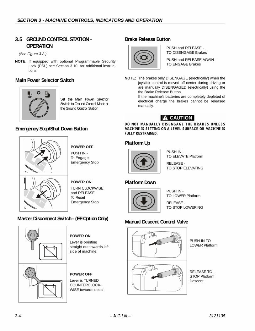
Main Power Selector Switch
Emergency Stop/Shut Down Button
Master Disconnect Switch - (EE Option Only)
Brake Release Button
NOTE: The brakes only DISENGAGE (electrically) when thejoystick control is moved off center during driving orare manually DISENGAGED (electrically) using thethe Brake Release Button.If the machine’s batteries are completely depleted ofelectrical charge the brakes cannot be releasedmanually.
CAUTIONDO NOT MAN UALLY DISENGAGE THE BRA KES UNLESSMACHINE IS SETTING ON A LEVEL SURFACE OR MACHINE ISFULLY RESTRAINED.
Platform Up
Platform Down
Manual Descent Control Valve
Set the Main Power SelectorSwitch to Ground Control Mode atthe Ground Control Station
POWER OFF
PUSH IN -To EngageEmergency Stop
POWER ON
TURN CLOCKWISEand RELEASE -To ResetEmergency Stop
POWER ON
Lever is pointing straight out towards left side of machine.
POWER OFF
Lever is TURNED COUNTERCLOCK-WISE towards decal.
-
-
xxxxxxx
PUSH and RELEASE -TO DISENGAGE Brakes
PUSH and RELEASE AGAIN -TO ENGAGE Brakes
PUSH IN -TO ELEVATE Platform
RELEASE - TO STOP ELEVATING
PUSH IN -TO LOWER Platform
RELEASE -TO STOP LOWERING
PUSH-IN TOLOWER Platform
RELEASE TO -STOP PlatformDescent
3-4 – JLG Lift – 3121135

SECTION 3 - MACHINE CONTROLS, INDICATORS AND OPERATION
Figure 3-2. Ground Control Station. (Machine Rear View)
1. Machine Status LCD Display 5. Platform Up 9. Hydraulic Oil Reservoir2. Main Power Selector Switch 6. Platform Down 10. Manual Descent Control Valve3. Emergency Stop 7. Battery Charging Status Indicators 11. Master Power Disconnect Switch (UL-EE Only)4. Brake Release 8. Charger A/C Input Receptacle
FILL TO LINE
2 31
654
11
+-
+-
7
8
9
10
-
xxxxxxx
3121135 – JLG Lift – 3-5

SECTION 3 - MACHINE CONTROLS, INDICATORS AND OPERATION
Machine Status LCD Display
At power-up and during operation the LCD display on theGround Control Module displays the current machineoperating status. The following illustration explains thesymbol indications.
In the LCD Display Symbols illustration item (2), the Func-tion Display or Function Disabled Indicators will vary asshown following:
LCD Display Fault Conditions
Table 3-3, LCD Display - Operating Fault Conditions showcommon LCD display Fault indications which may occurduring operation and are usually caused by either an errorin machine operation or a work area condition. Thesefault conditions can usually be corrected by the operatorand do not require a qualified mechanic to repair.
IMPORTANTAFTER A FAULT CONDITION IS CORRECTED THE MACHINEPOWER MAY NEED TO BE RECYCLED TO RESET THE GROUNDCONTROL STATION.
LCD Display Symbols
1. Battery Charge Indicator (BCI)2. Function Display or Function Disabled Indicators3. Hour Meter Display4. Fault Code Indicator 5. Fault Text Message Display (a)
Note: (a) When an Fault Code is indicated the LCD screen will alternate between the text and symbol display modes.
3
5
4
1 2
00
00
00000.0
DRIVE Disabled
LIFT UP Disabled
LIFT DOWN Disabled
Both LIFT UP and LIFT DOWNDisabled
Drive Speed Cut-Back (Turtle) ModeEngaged (When Platform is Elevated)
Battery Charger (AC) Plugged In
3-6 – JLG Lift – 3121135

SECTION 3 - MACHINE CONTROLS, INDICATORS AND OPERATION
Table 3-3. LCD Display - Operating Fault Conditions
FAULTCODE
PLATFORMCONSOLELED FAULT
CODE
LCD SYMBOL SCREEN LCD TEXT SCREENFAULT DESCRIPTION/MACHINE CONDITION
LOOK FOR THIS
— —Brakes Released(DRIVE Disabled)
To Engage Brakes - Press Brake Release Button on Ground Control Station
— — NONECharger AC Plugged InDRIVE Disabled
Unplug Charger AC Power Cord
— —Obstruction Sensor System(Platform Elevated)LIFT DOWN Disabled
Obstruction Under Platform or Sensor Defective
— —Programmable SecurityLock Password
Enter Code on PSL Keypad to Power-Up Machine
02 2Left PHP Bar UP(Platform Elevated)DRIVE and Lift UP Disabled
Lower Platform and Check the Left Pot Hole Protection Bar
03 2Right PHP Bar UP(Platform Elevated)DRIVE and Lift UP Disabled
Lower the Platform and Check the Right Pot Hole Protection Bar
04 3Tilt Condition(Platform Elevated)DRIVE and Lift UP Disabled
Lower the Platform and Drive off the Tilt Condition
13 6Traction ModuleOver Temperature(DRIVE Disabled)
Allow Drive System Traction Module to Cool BeforeOperating
17 7Ground Control ModuleOver Temperature(Machine Stopped)
Allow Ground ControlModule to Cool BeforeOperating
32 7Pump Motor Over Current(LIFT UP Disabled)
Platform Load Over Capacity
33 2Both PHP Bars UPDRIVE and Lift UP Disabled
Check for Object Blocking Both the Left and Right PHP Bars
34 —
Aux. #1 - Platform Gate Open or No Pressure on the Platform Enable switch.
Close Platform Gate or Depress Platform Enable switch during machineoperation.
35 —Aux. #1 - Platform Enable switch depressed during Machine Power-up.
Do Not Press on Platform Enable switch during Machine Power-Up.
NOTE: The fault conditions shown above are fault conditions which the Operator may be able to resolve. Should a faultoccur and be displayed on the LCD screen which cannot be corrected at the Operator’s level, the problem mustbe referred to a qualified mechanic. A complete table of Fault Codes is listed in the TroubleShooting Section of theService and Maintenance Manual.
00000.0
00000.0
00000.0
00000.0
02 0200000.0
03 0300000.0
04 0400000.0
13 1300000.0
17 1700000.0
32 3200000.0
33 3300000.0
3121135 – JLG Lift – 3-7

SECTION 3 - MACHINE CONTROLS, INDICATORS AND OPERATION
3.6 GROUND CONTROL STATION -PROGRAMMING
General
The DVL/DVSP machine Ground Control Station allowson-board programming of various component and controlfunction personality settings.
Programming may be required under circumstances suchas:
• Optional equipment has been added to the machine inthe field and a function must be enabled before opera-tion.
• Customizing the machine to fit a specific application,such as changing the LCD display language.
Programming Levels
There is one (1) password protected programming levelavailable to the Operator:
• Level-3: Operator’s Settings -Level-3 Password: 33271
Operator Programming Mode
In the Operator Level Programming Mode the followingitems are shown on the main menu (See Table 3-4 for Set-ting Range and Default Factory Setting):
• Tilt Sensor• Program
• Tilt Sensor
Allows viewing current tilt sensor individual X and Ydirection degree reading.
• Program
Allows programming of the items shown in Table 3-4,the following is a brief explanation of each program-ming item.
NOTE: There are two production modules available at thistime, one for North/South American and Europeanlanguages, and one for Asian languages. All pro-grammable items between these modules are identi-cal with the exception of language selection.
• Back To Main - When selected, will return to mainlevel menu.
• Set Language - Selects the language that text onthe LCD screen will be displayed.
• Set Sleep Time - Allows setting the length of timethe machine will remain powered up without controlinput before powering itself down.
• Set Polarity of Keypad Code - Turns on or off theProgrammable Security Lock switch circuit, ifequipped.
• Enable Detection of Horn Open Circuit - Enableshorn electrical circuit to be turned on (YES) or off(NO) if machine is equipped with a horn.
Table 3-4. DVL/DVSP Ground Control Station - Level 3 - Programmable Settings and Factory Presets.
Level-3: Operator Programmable Settings On LCD Display: YES = ! HIGH = ↑NO = ✕ LOW = ↓
LEVEL PROGRAMMABLE ITEMFACTORY PRESET
SETTING RANGE
3 Back to Main — Return to Main Menu
3 Set Language
NOTE: There are two production modules available at this
time, one for North/South American and European
Languages, and one for Asian Languages.
1 1 - English 6 - Italian2 - German 7 - Swedish3 - Dutch 8 - Brazilian Portuguese4 - French 9 - Finnish5 - Spanish
2 1 - English 3 - Japanese2 - Chinese
3 Set Sleep Time 5 MINS 0 - 60 MINS
3 Set Polarity of the Keypad Code LOW HIGH/LOW
3 Enable Detection of Horn Open Circuit NO (a) YES/NO
3 Enable Detection of Beacon Open Circuit NO (a) YES/NO
3 Forward Alarm Disable NO YES/NO
3 OSS Diagnostics NO YES/NO
Notes: (a) DVSP Models this feature is standard equipment and preset to YES at factory.
3-8 – JLG Lift – 3121135

SECTION 3 - MACHINE CONTROLS, INDICATORS AND OPERATION
• Enable Detection of Beacon Open Circuit -Enables mast/base beacon strobe electrical circuitsto be turned on (YES) or off (NO) if machine isequipped with either or both beacon strobes.
• Forward Alarm Disable - When turned on (YES) willdisable the alarm when driving forward.
• OSS Diagnostics - When turned on (YES) will causethe controller LCD to continuously display theObstruction Sensing System (OSS) Diagnostics untilturned back off (NO).......the machine will functionnormally, but only the OSS Diagnostics screen willdisplay until this setting is re-set to the off (NO) posi-tion.
Activating Programming Mode
NOTE: If machine does not power up, check that both theGround Control Station - Emergency Stop Button,and the Platform Control Console - Emergency StopButton, are in the RESET position.Also if machine is equipped with the (PSL) Program-mable Security Lock option, see Section 3.5 of thisOperators Manual for additional machine power-upsteps.
Entering Password
Programming Mode Selection
1. With machine power OFF, press and hold the BrakeRelease Button (1) on the Ground Control Station.
2. While holding the Brake Release Button in, powermachine up by turning the Main Power SelectorSwitch (2), to either the Ground Control or PlatformControl Mode.
3. Release the Brake Release Button (1) after machine ispowered up. The LCD display should now display fivezeros, one with a box around. Continue to next stepEntering Password.
1
2
1. The Brake Release button (1) moves the box from leftto right to select which digit to change.
2. Platform UP button (2) increases the numerical digit.
3. Platform DOWN button (3) decreases the numericaldigit.
4. Change all five digits (4) to match password level,then press the Brake Release button (1) again.
1. Use Platform UP/DOWN buttons (1) to move theselection box (2) up or down to select item to pro-gram.
2. Press the Brake Release button (3) to enter selectedmode then move on to Selecting Programmable Itemto Adjust.
1 2 3
00000
4
1
2
3
3121135 – JLG Lift – 3-9

SECTION 3 - MACHINE CONTROLS, INDICATORS AND OPERATION
Selecting Programmable Item to Adjust Adjusting Programmable Setting
TO EXIT Programming Mode after adjusting program-mable settings, power machine down with either theMain Power Selector Switch or Emergency Stop But-ton.
1. Use the Platform UP/DOWN buttons (1) to scrollthrough the list of programmable items available toyour programming level.
2. Once a programmable item to be adjusted is selected,press the Brake Release button (2) to enter that set-tings’ adjustment mode.
12
1. Adjust the programmable setting using the PlatformUP/DOWN buttons (1), see Table 3-4 for range of set-tings for that item.
2. Once parameter is set for the programmable item,press the Brake Release button (2), this will enter theparameter and return you to the Programmable Set-tings Menu.
12
3-10 – JLG Lift – 3121135

SECTION 3 - MACHINE CONTROLS, INDICATORS AND OPERATION
3.7 PLATFORM CONTROL CONSOLE OPERATION - (MACHINES SERIAL NUMBER - 0130007616 TO PRESENT)
General
The following conditions must be met before the machinecan be operated from the platform control console:
• Ground Control Station - Main Power Selector Switchmust be set to PLATFORM CONTROL MODE.
• Ground Control Station - Emergency Stop/Shut DownButton must be in the RESET position (POWER ON).
NOTE: See Section 3.5 on page 3-4, for Ground ControlStation operation.
• Platform Console - On/Off Key Switch must be set tothe ON position.
• Platform Console - Emergency Stop/Shut Down Buttonmust be in the RESET position (POWER ON).
• If equipped with the OPTIONAL - PSL (ProgrammableSecurity Lock) it must be set to the ON position.
NOTE: See Section 3.10 on page 3-18, for location and PSLinstructions.
NOTE: SLEEP MODE - During operation if no control func-tions have been activated for 10 minutes (defaultprogrammable setting), the ground control modulewill power the machine down to conserve batterypower. Cycle power back on using either the mainpower selector switch (key) or the emergency stop/power down button either on the platform controlleror on the ground control station.
1. On/Off Key Switch -(See page 3-12)
2. Emergency Stop/Shut Down Button -(See page 3-12)
3. Function Enable Lever - (on front of joystick)
(See page 3-13)
4. Multifunction Joystick Control -(See page 3-13)
5. Drive Speed Setting Selector Switch -(See page 3-14)
6. Platform Control Display Panel -(See page 3-12)
7. Horn Button - (See page 3-13)
8. Drive/Lift Mode Selector Switch -(See page 3-13)
Figure 3-3. Platform Control Console -(Machines Serial Number - 0130007616 to Present)
1
2
4
5
6
7
8
3
3121135 – JLG Lift – 3-11

SECTION 3 - MACHINE CONTROLS, INDICATORS AND OPERATION
Platform On/Off Key Switch
Set the ON/OFF Key Switch to the OFF position to powermachine down.
NOTE: If necessary, when machine is not in use, removekey from platform key switch to disable machine fromunauthorized use.
NOTE: During operation the operator in the platform canprevent unauthorized control of the machine (fromthe Ground Control Station) by either switching theOn/Off Key to the OFF position, or activating theEmergency Stop Button on the platform control con-sole.
Platform Emergency Stop/Shut Down Button
NOTE: The Platform and Ground Control Station Emer-gency Stop/Shut Down Buttons must both be in theRESET position to operate machine.
Platform Control Display Panel
1. Battery Charge/Flash Code Indicator LEDS
On normal power-up and operation this series of ten(10) LEDs visually indicates the amount of chargeremaining in the batteries.
The number of LEDs lit will change depending on thelevel of charge in the batteries.
• (+) All Three (3) GREEN LEDs lit up indicate maxi-mum battery charge.
• Four (4) YELLOW LEDs indicate a two thirds to onethird battery charge remaining.
• (–) Three (3) RED LED’s lit indicate minimum batterycharge remaining. The machine will continue tooperate at this charge level but will begin to indicatelow battery voltage warning indicators.
NOTE: For more information on Battery Warning Level Indi-cators See “Battery Low Voltage Warning Indicators”on page 3-3.
This set of ten (10) LEDs will also indicate a flash (fault)code if operating problems are detected by theGround Control Station.
NOTE: LED Flash (Fault) Code indications that can be cor-rected by the operator are shown on Table 3-3 onpage 3-7, this section of the manual.
At the Platform Control Console - Set the On/Off Key Switch to the ON position (2) to operate machine.
1. OFF Position2. ON Position
POWER OFF
PUSH IN -TO ENGAGEEmergency Stop
POWER ON
TURN CLOCKWISEand RELEASE toRESET Emergency Stop
12
Figure 3-4. Platform Control Display Panel.
1. Battery Charge/Flash Code LEDS2. Drive Mode Indicator
3. Lift Mode Indicator4. Drive Speed Setting
Indicator
3
14
2
3-12 – JLG Lift – 3121135

SECTION 3 - MACHINE CONTROLS, INDICATORS AND OPERATION
2. Drive Mode Indicator
When the Drive/Lift Mode Selector Switch is set toDRIVE MODE the round LED indicator on that portionof the display panel will light up indicating the DRIVEMode active.
3. Lift Mode Indicator
When the Drive/Lift Mode Selector Switch is set to LIFTMODE the round LED indicator on that portion of thedisplay panel will light up indicating the LIFT Modeactive.
4. Drive Speed Setting Indicator
The five (5) GREEN LEDs on the top of this indicatordisplay the drive speed setting with the TURTLE (onthe left) representing the MINIMUM speed setting andthe RABBIT (on the right) representing the MAXIMUMspeed setting.
Drive/Lift Mode Selector Switch
Horn Button
Joystick Function Enable Lever
Multifunction Joystick Control
The joystick will operate the following machine functions:
• Drive
• Platform Lift Up and Down
NOTE: Use the Drive/Lift Mode Selector Switch to selectwhich function the joystick will operate.The selected operating mode will only remain activefor 5 seconds if the function is not operated.Remember to press and hold the joystick functionenable lever to operate any joystick functions.
WARNINGWHEN DRIVING WITH PLATFORM LOWERED, DO NOT ATTEMPTTO DRIVE MACHINE UP A RAMP (GRADE) OF GREATER THANFIFTEEN PER CENT (15%).
DRIVING WITH PLATFORM ELEVATED IS RESTRICTED TO ASMOOTH, FIRM AND LEVEL SURFACE WITHIN 1.5 DEGREES OFLEVEL IN ANY DIRECTION.
Drive/Lift ModeSelector Switch
1. LIFT Mode
2. DRIVE Mode
PUSH the rocker switch to select mode of operation.Whichever mode is selected the appropri-ate LED indicator on the display panel below will light up showing which mode has been activated for joystick operation.
IMPORTANT:
The selected mode will only remain active for 5 sec-onds if the function is not operated.
1 2
When the machine is powered on, pressing this button will sound the Horn.
Joystick Function Enable Lever
The Function Enable lever on the front of the joystick con-trol, must be engaged and held in during any joystick operation.
3121135 – JLG Lift – 3-13

SECTION 3 - MACHINE CONTROLS, INDICATORS AND OPERATION
Drive Mode
Lift Mode
WARNINGTHE GROUND CONTROL STATION CONTAINS A 1.5 DEGREETILT ALARM, IF THE TILT ALARM HAS BEEN ACTIVATED, THEPLATFORM WILL NOT ELEVATE. ALSO IF THE TILT ALARM HASBEEN ACTIVATED WHEN THE PLATFORM IS ELEVATED, THEDRIVE AND LIFT UP FUNCTIONS WILL BE DISABLED UNTIL THEPLATFORM IS COMPLETELY LOWERED, THEN DRIVEN OFF THETILT CONDITION.
Drive Speed Setting Controls
NOTE: When the platform is elevated the maximum drivespeed is automatically cut-back to 1/4th the speedwhen the platform is fully lowered. The Ground Con-trol Module-LCD screen will display a turtle when inthis mode, See page 3-6 - Ground Control - LCDStatus Display in this section of the manual.
1. Activate the Drive Mode using the Drive/Lift Mode Selector switch.
Within 5 seconds of activa-tion - ENGAGE and HOLD the JOYSTICK ENABLE LEVER then move the joy-stick in the desired direction of travel. Drive power is applied proportionally the further the joystick is moved off center.
1. Activate the Lift Mode using the Drive/Lift Mode Selector switch.
2. Platform LIFT DOWN Direction
3. Platform LIFT UPDirection
Within 5 seconds of activa-tion - ENGAGE and HOLD the JOYSTICK ENABLE LEVER then move the joystick in the direction of LIFT (3) OR LOWER (2).
1
2
3
Drive Speed Setting Selector Switch
1. Selector Switch (on top of joystick)
Each PRESS on this side of the switch will DECREASE maximum drive speed.(FEWER LEDs Lit up on the Drive Speed Indicator.)
Each PRESS on this side of the switch will INCREASE maximum drive speed.(MORE LEDs Lit up on the Drive Speed Indicator.)
1
3-14 – JLG Lift – 3121135

SECTION 3 - MACHINE CONTROLS, INDICATORS AND OPERATION
3.8 PLATFORM CONTROL CONSOLE OPERATION - (MACHINES BEFORE SERIAL NUMBER - 0130007616)
At Ground Control Station Emergency Stop/Shut-Down Button
Figure 3-5. Platform Control Console - (Machines Before Serial Number - 0130007616
1. Battery Charge/Fault Code (LEDs) 4. Increase Max. Drive Speed 7. Platform Function (Enable)2. Max. Drive Speed Setting (LEDs) 5. Horn 8. Joystick with Enable Button3. Decrease Max. Drive Speed 6. Drive Function (Enable) 9. Emergency Stop
6
3
2
1 4
7
8
9
5
Set the Main Power SelectorSwitch to Platform ControlMode at the Ground ControlStation. (See Figure 3-2.)
POWER OFF
PUSH IN -TO ENGAGEEmergency Stop
POWER ON
TURN CLOCKWISEand RELEASE -TO RESETEmergency Stop
3121135 – JLG Lift – 3-15

SECTION 3 - MACHINE CONTROLS, INDICATORS AND OPERATION
Battery Charge/Fault Code LED Indicator
On normal power-up and operation this series of LEDsvisually indicates the amount of charge left in the batter-ies.
• (+) GREEN LEDs lit indicate maximum charge.
• (–) RED LED’s lit indicate minimum charge remaining.
• The number of LEDs lit will change depending on thelevel of charge in the batteries.
If battery voltage falls below 16.8 volts a fault condition willoccur and the machine will stop operating. The batterieswill need recharged.
NOTE: LED Fault Code indications are in Table 3-3, LCDDisplay - Operating Fault Conditions, this section ofthe manual.
Driving Machine
WARNINGWHEN DRIVING WITH PLATFORM LOWERED, DO NOT ATTEMPTTO DRIVE MACHINE UP A RAMP (GRADE) OF GREATER THANTWENTY PER CENT(20%), AS TIPPING COULD OCCUR.
1. Enter the platform.
– +
POINT & GO®
The Joystick can bemoved in any directionoff center.
Drive Power is appliedproportionally the fur-ther the Joyst ick ismoved off center.
2. PRESS and RELEASE theDrive Function Button. Theflashing LED indicates thefunction is active. The functionremains active 3 to 4 seconds.
3. While the Drive Function isactive. PRESS and HOLD theenable button on top the joy-stick
4. Move the joystick in thedesired direction of travel. TOSTOP the machine return thejoystick back to center.
RESET
POINT G
POINT G
3-16 – JLG Lift – 3121135

SECTION 3 - MACHINE CONTROLS, INDICATORS AND OPERATION
Adjusting Maximum Drive Speed Control
NOTE: When the platform is elevated the maximum drivespeed is cut-back to 1/4th the speed when the plat-form is fully lowered. The Ground Control Module-LCD screen will display a turtle when in this mode,see Machine LCD Status Display in this section ofthe manual.
Maximum Drive Speed Indicator
Elevating/Lowering the Platform
WARNINGIF THE TILT ALARM HAS BEEN ACTIVATED, THE PLATFORMWILL NOT ELEVATE. ALSO IF THE TILT ALARM HAS BEEN ACTI-VATED WHEN THE PLATFORM IS ELEVATED, THE DRIVE FUNC-T I O N W I L L B E D I S A B L E D U N T I L T H E P L A T F O R M I SCOMPLETELY LOWERED.
NOTE: For DVSP Models equipped with the optionalObstruction Sensing System, see Section 3.14 foradditional platform operation instructions.
1. Drive the machine to the area where overhead work isto be performed and position the machine into it’sapproximate work position.
5. If necessary, reposition (drive) lift using platform con-troller joystick to bring work object within reach.
3.9 PARKING MACHINE
1. Drive machine to a well-protected and well-ventilatedarea.
2. Ensure the platform is fully lowered, turn the mainpower selector switch to the OFF position (centered).
NOTE: If required, charge batteries in preparation for nextwork day.
Indicates currentMaximum DriveSpeed Setting.Slow to Fast.
1. Each Press of this button willreduce the Maximum DriveSpeed allowed.(LESS LEDs Lit.)
2. Each Press of this button willincrease the Maximum DriveSpeed allowed.(MORE LEDs Lit.)
2. PRESS and RELEASE thePlatform Function Button. Theflashing LED indicates thefunction is active and willremain active 3 to 4 seconds.
3. While the Platform Function isactive. PRESS and HOLD theEnable Button on top the Joy-stick
4. Push the Joystick FORWARDfrom center TO ELEVATE thePlatform.
TO STOP platform movementreturn the joystick back tocenter.
Pull the Joystick BACK fromcenter TO LOWER the Plat-form.
3121135 – JLG Lift – 3-17

SECTION 3 - MACHINE CONTROLS, INDICATORS AND OPERATION
3.10 PROGAMMABLE SECURITY LOCK (PSL™) (DVL/DVSP - OPTION)
The optional Programmable Security Lock switch can beprogrammed with a four (4) digit operators code to allowonly those persons with the code to power-up and oper-ate the machine.
PSL™ Box and Ground Control Locations
Machine Power Up using the PSL™
NOTE: When entering code on the key pad, a short beepindicates a properly depressed key, a long beep indi-cates an error in depressing key. If an error occurs,
you must restart the code entry process again.
1. Enter the four digit code on the PSL key pad. TheACCEPT - AMBER LED indicator will be lit if the code iscorrect.
2. Press the keypad ON button. The ON - GREEN LEDindicator will light and power will be supplied to theGround Control Station.
3. At the ground control station, turn the main powerselector switch from OFF to either Platform ControlMode or Ground Control Mode.
4. The machine will now operate normally.
Machine Power Down
1. At the Ground Control Station set the main powerselector switch to the OFF position.
2. Press the OFF button on the PSL keypad. No LEDs onthe PSL box will be lit.
Changing the Operator’s Code
The PSL Operators Code can be changed by a supervisorshould the need occur. A separate permanent Supervi-sor’s Code matched to the serial number of the PSL box isincluded on a sheet in the PSL user manual supplied withthe machine.
1. Enter the Supervisor’s code on the key pad. The PRO-GRAM - RED LED will be lit if correct code is entered.
NOTE: ON or OFF cannot be one of the four digits of thenew Operator’s code.
2. Enter a new four (4) digit Operator’s code on the key-pad. The ACCEPT - AMBER LED will light up if the newOperator’s code is accepted.
3. Press the OFF button on the keypad to activate thenew Operator’s code.
NOTE: The new Operator’s code will remain in the PSL evenwhen power is removed from the equipment, or untilthe Supervisor changes the Operator’s code.
Figure 3-6. PSL™ Switch & Ground Control Station Locations - At Rear of Machine.
1. PSL Switch (Inside Right Cover) (a)
2. Ground Control Station
Note: (a) Machines with bolt on (fixed) covers, the PSLSwitch is mounted on outside of right cover.
Figure 3-7. PSL™ Switch Controls & Indicators.
1. ON (Green LED) 4. Key Pad2. ACCEPT (Amber LED) 5. OFF Switch3. PROGRAM (Red LED) 6. ON Switch
1
2
PSL™
1 2 3
4 5 6
7 8 9
0
4
5
123
6
3-18 – JLG Lift – 3121135

SECTION 3 - MACHINE CONTROLS, INDICATORS AND OPERATION
3.11 PLATFORM CONFIGURATIONS
STANDARD PLATFORM (DVL)
Model Max. Capacity20DVL 350 lb. (160kg)
15DVL 500 lb. (230kg)
1. Sliding Side Entry Gate 3. Lanyard Attach Point - 2. Platform Control Console (Left side of mast)
MOLDED PLATFORM (OPTION) - SHOWN w/MATERIAL TRAY
Model Platform & TrayCombined Max. Capacity
Material TrayMax. Capacity
20DVL 350 lb. (160kg) 100 lb. (45kg)
15DVL/15DVSP 500 lb. (230kg) 150 lb. (70kg)
1. Swing Up Side Entry Gate 3. Lanyard Attach Point - (on mast)
2. Entry Gate Latch 4. Platform Control Console
2
3
1
3
2
1
4
EXTENDIBLE PLATFORM (GULL-WING ENTRY - NON CE)
Model Max. Capacity20DVL 350 lb. (160kg)
15DVL/15DVSP 500 lb. (230 kg)
1. Gullwing Entry Gate 4. Extension Slide/Lock Handle 2. Entry Gate Latch 5. Platform Control Console 3. Lanyard Attach Point (on mast) 6. Sliding Extendible Section
EXTENDIBLE PLATFORM (SLIDING BAR ENTRY - CE ONLY)
Model Max. Capacity20DVL 350 lb. (160kg)
15DVL/15DVSP 500 lb. (230 kg)
1. Sliding Bar Entry Gate 4. Platform Control Console 2. Lanyard Attach Point (on mast) 5. Sliding Extendible Section 3. Extension Slide/Lock Handle
1
3 4
4
5
6
2
1
2
3
3
4
5
3121135 – JLG Lift – 3-19

SECTION 3 - MACHINE CONTROLS, INDICATORS AND OPERATION
StockPicking Platform Operation
The stockpicking platform is available in two (2) versions.
• Fixed side-rail version
• Folding side-rail version
CAUTIONTHE STOCKPICKER PLATFORM ALLOWS THE MACHINE TO BEOPERATED IN AN OPEN RAIL CONFIGURATION (SEE ILLUSTRA-TION).
CE SPECIFICATION MACHINES:TH E O P ERA TO R MU ST WE AR A FU LL BO DY HARN ES SEQUIPPED WITH A LANYARD SHORT ENOUGH TO PREVENT AFA LL FR OM T H E PL A T FO R M . TH E LA N YA R D M U S T B EATTACHED TO THE AUTHROIZED LANYARD POINT. ALSO, JLGRECOMMENDS THAT CE SPECIFICATION MACHINES EQUIPPEDWITH THE STOCKPICKER PLATFORM ARE ONLY TO BE USEDFOR STOCKPICKING APPLICATIONS.
NON-CE UNITS:THE OPERATOR MUST WEAR A FULL BODY HARNESS WITH ALANYARD (MAX. 6 FT. (1M) ATTACHED TO THE AUTHORIZEDLANYARD POINT OR A BODY BELT EQUIPPED WITH A LANYARDSHORT ENOUGH TO PREVENT A FALL FROM THE PLATFORM.
WHILE OPERATING THE MACHINE IN THE OPEN RAIL CONFIGU-RATION, ALWAYS OPERATE THE MACHINE FROM THE REAR OFTHE PLATFORM WITH THE MID-GATE CLOSED AND THE PLAT-FORM CONTROL CONSOLE ATTACHED TO THE FIXED PORTIONOF THE GUARDRAIL.
STOCKPICKER PLATFORM(WITH FOLDING SIDE-RAILS) (DVSP)
Model Max. Capacity
15DVSP 500 lb. (230 kg)
20DVSP 400 lb. (180 kg)
1. Primary Entrance/Exit Gate 4. Platform Control Console2. Primary Entrance Latch 5. Mid-Gate3. Lanyard Attach Point - 6. Gate Release/Lock Pins (on side of mast) 7. Secondary Exit Gate
6
6
2
1
34
5
7
STOCKPICKER PLATFORM(OPEN RAIL CONFIGURATION) (DVSP)
1. Platform Mid-Gate (enter rear of platform and close mid-gate
when driving with front rails open).
2. Open Rail Configuration work area. (See previous Caution about
fall protection requirements).
3. Platform Control Console attached to fixed side-rail in the rear ofthe platform.
1
3
2
3-20 – JLG Lift – 3121135

SECTION 3 - MACHINE CONTROLS, INDICATORS AND OPERATION
3.12 FALL PROTECTION - LANYARD ATTACHMENT
CAUTIONJLG INDUSTRIES, INC. RECOMMENDS THE OPERATOR IN THEPLATFORM WEAR A FULL BODY HARNESS WITH A LANYARDATTACHED TO AN AUTHORIZED LANYARD ANCHORAGE POINT.
The main lanyard attach point for all DVL/DVSP machinesis located on the lower left side of the mast platformheader, just behind the operators platform.
CAUTIONAFTER ENTERING THE PLATFORM, BEFORE BEGINNING OPER-ATION ALWAYS CLOSE THE PLATFORM ENTRY GATE(S).
3.13 QUICK-CHANGE PLATFORM MOUNTINGDVL Model Lifts are equipped with quick-change platformmounts which allow quick removal and installation of cur-rently available quick-change platforms.
NOTE: DVSP Models require the installation of the Quick-Change mount kit to use Quick-Change Platforms.
Platform Removal
1. Remove the platform control console from the platformand lay aside.
2. Remove both upper and lower mount attach pinssecuring the platform support rails to the mast mount-ing channels.
3. Swing and lift the platform out of the mounts and layaside.
Platform Installation
1. Set platform in upper and lower mounts.
2. Install attach pins in upper and lower mounts.
3. Attach platform control console to platform rail.
WARNINGENSURE ALL PINS AND FASTENERS ARE INSTALLED ANDSECURE PRIOR TO OPERATION.
1. Upper Platform Mount 3. Lower Platform Mount2. Upper Mount Attach Pins 4. Lower Mount Pins
1
3
2
4
3121135 – JLG Lift – 3-21

SECTION 3 - MACHINE CONTROLS, INDICATORS AND OPERATION
3.14 OBSTRUCTION SENSING SYSTEM (DVSP -
OPTION)
System Description
The Obstruction Sensing System (OSS) is designed todetect the presence of obstructions within a predeter-mined detection zone beneath the platform, when lower-ing the platform from an elevated position.
NOTE: The OSS only operates normally when the GroundControl Module - Power Selector Switch is set toPLATFORM CONTROL MODE.When the Power Selector Switch is set to GROUNDCONTROL MODE the OSS will detect an obstruc-tion but will not stop platform downward movementor sound the horn. However, the OSS Control Mod-ule LED will flash if a sensor detects the presence ofan object.
Operation
NOTE: See Figure 3-9. for the location of the OSS Elec-tronic module.
When the machine is powered on a RED LED located onthe OSS electronics module will illuminate. During plat-form lowering, if no obstructions have entered the detec-tion zone beneath the platform, the platform will lowernormally.
If an obstruction is detected within the detection zonebeneath the platform, the platform will;
• Stop Lowering
• The RED LED on the electronics module will flash
• The horn will sound three short blasts
If an obstruction is detected, have the obstruction clearedby someone on the ground or carefully drive the lift untilclear of the obstruction. Reset the OSS by pressing thehorn button on the platform control once and continuemachine operation. Should the OSS falsely detect anobstruction, the system can be overridden by pressingand holding the horn button while operating the platformlowering controls.
WARNINGALWAYS CHECK THE AREA UNDER THE PLATFORM IS CLEAROF OBSTRUCTIONS BEFORE LOWERING THE PLATFORM.
OSS Pre-Start Inspection
(See Figure 3-9.)
From ground controls, raise platform approximately 5'-6'.The RED LED on the electronic module will be illuminatedwhen power is applied. If an obstruction, such as a pad ofpaper is placed under any of the transducer sensorarrays, the RED LED will flash and remain flashing whilethe obstruction is present and stop flashing 3 secondsafter the obstruction is removed. Check the operation ofeach transducer sensor array by placing an object individ-ually under each sensor array (within approximately 6"-12")and checking if the RED LED starts to "flash", and stopsflashing 3 seconds after the obstruction is removed. Also,inspect the transducer arrays and electronic module forphysical damage, loose wires, loose mounting hardware,etc.
Figure 3-8. OSS Transducer Sensor Array Location.
1. Transducer Arrays #1 through #62. Underside of DVSP Platform
#5
#3
#1#2
#4
#6
2
1
3-22 – JLG Lift – 3121135

SECTION 3 - MACHINE CONTROLS, INDICATORS AND OPERATION
3.15 TRANSPORTING, LIFTING ANDTIE DOWN PROCEDURES
General
All DVL Series and DVSP Model Personnel Lifts may betransported to a work site using the following methods:
• Driving the machine around on its base wheels if travelsurface area permits.
• Loaded, IN AN UPRIGHT POSITION ONLY onto aheavy-duty vehicle with the payload capacity capableof supporting the full weight of the machine (Checkmachine gross weights in the Operating Spec Chart atthe beginning of this Section).
• Moved with a fork-lift truck using the fork-lift pockets inthe base frame.
Truck Transport
CAUTIONDO NOT TRANSPORT THE MACHINE IN A HORIZONTAL POSI-TION DUE TO LEAKAGE OF BATTERY ACID FROM THE BATTER-IES OR HYDRAULIC FLUID FROM THE HYDRAULIC RESERVOIR.
The machine may be winched onto a tilted roll-back truckbed (see important note following) which has been rolledback to ground level. Disengage the brakes and alwayswinch (pull) from the mast (rear) end of the machine,using the rear tie-down loop attached to the base frame.
IMPORTANTDO NOT ATTEMPT TO DRIVE MACHINE ONTO, OFF OF, OR PUSHMACHINE ONTO A TILTED ROLL-BACK TRUCK BED.THE DVL AND DVSP MACHINES POWER MODULE COULD SUS-TAIN SERIOUS DAMAGE WHEN THE UNIT IS PUSHED, ORTOWED AT SPEEDS GREATER THAN 2 MPH.
WHEN TOWING OR WINCHING, THE MACHINE’S BRAKES MUSTBE DISENGAGED.
RE-ENGAGE THE BRAKES ONCE MACHINE IS IN PLACE WITHTRUCK BED LEVEL AND READY FOR TIE DOWN.
TIE DOWN LOOPS ARE PROVIDED ON BOTH ENDS OF THE BASEFRAME TO SECURE MACHINE TO BED OF TRANSPORT VEHICLE.
Figure 3-9. OSS - Pre-Start Inspection of Operation.
1. Electronic Module LED Indicator (a)2. Detection Zone 3. Place a pad of paper or similar size object, 6 to 12 in. (15 to 30cm) individually beneath each transducer to check detection.
Notes: (a) The LED Indicator will flash when an object isdetected at each sensor. Remove object and allowthe LED to stop flashing before testing next sensor.
1
2
3
3121135 – JLG Lift – 3-23

SECTION 3 - MACHINE CONTROLS, INDICATORS AND OPERATION
Machine Tie-Down
With machine in position to be tied down and brakesengaged, use the following guidelines for restraining themachine during transport.
IMPORTANTUSE OF EXCESSIVE FORCE WHEN SECURING MACHINE (DRIVEWHEEL LOAD), CAN CAUSE DAMAGE TO THE MACHINES DRIVEWHEEL COMPONENTS.
1. Secure machine with an adequate chain attachedthrough the tie down loops located at the front and rearof machine. (See Figure 3-11.)
2. The chain should be securely tightened with a force ofapproximately 100 lb. applied two feet from the pivothandle.
Crane Hook Accessory (DVL Option)
NOTE: Lifting devise must be capable of handling the grossweight of the machine, see the Operating Specifica-tions table at the beginning of this Section.
Fork-Lift Truck Transport
All DVL and DVSP Model Lifts are equipped with wide fork-lift pockets running through the base frame. (See Figure 3-11.) This allows the machine to be either transportedaround a work area or lifted onto a higher level using astandard fork-lift truck.
NOTE: Fork-lift trucks must be capable of handling thegross weight of the machine, see the OperatingSpecifications table at the beginning of this Section.
Figure 3-10. Crane Hook Accessory
1. Crane Hook Attachment 2. Back of Mast
1
2
Figure 3-11. Forklift Truck Lifting Pockets and Machine Tie Down Bar Locations.
1. Rear Tie-Down Loop 2. Fork Lift Pockets 3. Front Tie-Down Loop
3
2 2
3-24 – JLG Lift – 3121135

SECTION 3 - MACHINE CONTROLS, INDICATORS AND OPERATION
3.16 RUG CARRIER ACCESSORY(DVSP - OPTION)
NOTE: The Rug Carrier accessory is available only on theJLG DVSP model and is not authorized for use withany other JLG lift. The Rug Carrier Accessory isintended for use in hanging and removal of rugs inhanging display racks only. Use for any other pur-pose is not authorized by JLG.
General
The Rug Carrier Accessory consists of two pivoting armsmounted to the DVSP platform left side rails. The pivotingarms are locked in the plane of the platform side rail whennot in use (the stowed position). The arms are locked intoposition at approximately 90 degrees to the left side plat-form side rails when in use (the carry position). The pivot-ing arms’ position can be changed by lifting each arm torelease the lock, rotating the arm, and lowering each armback into a locked position.
Pre-Start Inspection
Prior to use of the Rug Carrier accessory, check the fol-lowing;
• Carrier arm mounting is secure to the platform railing,no missing or damaged fasteners.
• The arm lock pins are in place and working properly.
Hanging a Rug using the Rug Carrier Accessory Arms
The following is a description for use of the Rug Carrieraccessory in hanging rugs on horizontal pivoting arm dis-play racks.
1. Select the intended location in the display for mountingthe rug. Open the display rack to provide adequatespace for the DVSP lift and rug.
2. With the Rug Carrier Accessory arms stowed, drive theDVSP into position prior to loading the rug.
3. Swing and lock Rug Carrier Accessory arms into thecarry position.
4. Load the rolled rug with the finished side facing theplatform. As required, use an assistant to load the rugonto the Rug Carrier Accessory arms.
5. Make sure that the rug is centered over its length onthe Rug Carrier Accessory.
6. Elevate the platform to the required height for mount-ing the rug onto the display arm.
7. Properly attach the rug to the display arm. Never climbonto the platform rails for any reason.
8. After adequately attaching the rug to the display arm,lower the platform, stow the Rug Carrier Accessoryarms.
9. As required reposition and elevate the DVSP to com-pletely attach the rug.
Positioning Rug Carrier Arms
1. Carry Position 3. Lift Arm Up, Swing2. Stowed Position and Lock into Position
Positioning Carpet Roll On Rug Carrier
1. Center Carpet on Arms 3. Platform Front2. Rest on Arms Here (a)
Note: (a) Maximum Capacity of Arms - 150 lb. (68kg)
3
21
2
1
3
3121135 – JLG Lift – 3-25

SECTION 3 - MACHINE CONTROLS, INDICATORS AND OPERATION
Removing a Rug using Rug Carrier Accessory Arms
This section describes the use of the Rug Carrier acces-sory in removing a rug from a horizontal pivoting arm dis-play rack.
1. Select the intended location in the display for removalof the rug. Open the display rack to provide adequatespace for the DVSP lift and rug.
2. With the Rug Carrier Accessory arms stowed, drive theDVSP into position prior to loading the rug.
3. Swing and lock the Rug Carrier Accessory arms intothe carry position.
4. Elevate the platform a few feet. Start to roll the rug ontothe Rug Carrier Accessory arms.
5. Be certain the rug is centered over its length on theRug Carrier Accessory.
6. While elevating to the required height for removing therug from the display arm, continue to roll the rug until itis completely rolled up on the carrier arms.
7. Properly remove the rug from the display arm. Neverclimb onto the platform rails for any reason.
8. After adequately removing the rug from the displayarm, lower the platform.
9. Remove the rug from the Rug Carrier Accessory. Ifrequired, use an assistant to unload the rug from theRug Carrier Accessory Arms.
10. Replace the Rug Hanger Accessory arms to thestowed position for normal operation.
CAUTIONTHE RUG CARRIER ACCESSORY ARMS MUST BE LOCKED INTHE STOWED POSITION WHEN NOT IN USE.
EXTREME CAUTION MUST BE EXERCISED AT ALL TIMES WHILETHE RUG CARRIER ACCESSORY IS IN USE (DRIVING, RAISINGAND LOWERING) TO PREVENT OBSTACLES AND PERSONNELFROM STRIKING THE LOAD.
WHEN DRIVING WITH A RUG WITHIN THE RUG CARRIER ACCES-SORY, THE RUG MUST BE PROPERLY SECURED TO PREVENTINADVERTENT MOTION OR MOVEMENT OF THE RUG AND MUSTNOT EXCEED THE RATED CAPACITY OF THE RUG CARRIERACCESSORY.
NEVER OVERLOAD THE RUG CARRIER ACCESSORY. MAXIMUMCAPACITY OF THE RUG CARRIER ACCESSORY IS 150 LBS.
THE COMBINED WEIGHT OF PERSONNEL, MATERIALS, EQUIP-MENT PLUS ANY LOAD ON THE RUG CARRIER ACCESSORYMUST NOT EXCEED THE MAXIMUM CAPACITY OF THE PLAT-FORM.
NEVER USE A RUG CARRIER ACCESSORY THAT HAS DAMAGEOR LOOSE MOUNTINGS. IMMEDIATELY REPORT ANY DAMAGETO APPROPRIATE PERSONNEL. DISCONTINUE USE OF THERUG CARRIER ACCESSORY UNTIL ALL DISCREPANCIES HAVEBEEN CORRECTED.
Removing Rug From Display Arm.
1. Roll Rug onto Rug Carrier while Elevating Platform2. Rug Carrier in Carry Position
1
2
3-26 – JLG Lift – 3121135

SECTION 3 - MACHINE CONTROLS, INDICATORS AND OPERATION
3.17 STOCK-PICKER HANGER ACCESSORY
NOTE: The stock-picker hanger accessory is available onlyon the JLG DVSP model and is not authorized foruse with any other JLG lift. This hanger accessory isintended for use in placing or retrieving stock itemssuch as bicycles, ladders, etc., on racks or shelvesabove ground level. Use for any other purpose is notauthorized by JLG.
The hanger accessory is a pivoting arm mounted to theDVSP platform rail. The hanger accessory can bemounted to either side of the platform individually, or twocan be mounted, one on each side of the platform. Eachindividual hanger has a maximum load capacity of 100 lb.(45kg).
The hanger arm can be pivoted out of the way parallelwith the platform side rails when not in use, (the stowedposition). The hanger arm is pinned into position at 90degrees to the platform side rails when in use, (the carryposition).
Pre-Start Inspection
Prior to use of the hanger accessory, check the following;
• Hanger arm mounting is secure to the platform railing,no missing or damaged fasteners.
• The hanger arm lock pin is in place and secure.
CAUTIONTHE COMBINED WEIGHT OF PERSONNEL, MATERIALS, EQUIP-MENT PLUS ANY LOAD ON THE HANGER ARM ACCESSORYMUST NOT EXCEED THE MAXIMUM LOAD CAPACITY OF THEPLATFORM.
Loading and Transporting an Item using the Hanger Accessory
Use the following steps as a guide when loading andtransporting an object with the hanger accessory arm.
1. Keep the hanger arm in the stowed position when notin use.
2. When ready to use, pull the lock pin from the stowedposition hole and swing the hanger arm into the carryposition. Place pin in the carry position hole locking thehanger arm in place.
3. Load the object onto the hanger arm and use thehanger arm strap to secure the object during transport.
IMPORTANTDVSP MACHINE’S EQUIPPED WITH THE OBSTRUCTION SENSINGSYSTEM (OSS) OPTION – OBJECTS PLACED ON THE HANGERACCESSORY AND EXTENDING BELOW THE BASE OF THE PLAT-FORM MAY CAUSE AN OSS DETECTION - SOUNDING THE HORN
AND PREVENTING THE PLATFORM FROM LOWERING. IF NECES-SARY, REPOSITION THE OBJECT OUT OF THE OSS DETECTIONZONE.
4. Be aware of clearance above, below, and around theobject when driving and lifting or lowering the platform.
Stock Picker Hanger - Carry Position
1. Mounting Bracket 4. Lock Pin (Carry Position)2. Hanger Arm (Carry Position) 5. Hanger Arm Strap3. Capacity Decal (a)
Notes: (a) Maximum load capacity of hanger is 100 lb. (45kg).
Stock Picker Hanger - Stowed Position
1. Hanger Arm (Stowed Position)3. Hanger Arm (Carry Position)2. Lock Pin (Stowed Position)
1
2
4
3
5
1 2
3
3121135 – JLG Lift – 3-27

SECTION 3 - MACHINE CONTROLS, INDICATORS AND OPERATION
Figure 3-12. DVL Series Decal Installation Chart - (See Table 3-5 for Specification)
1
521
10
12
17
8
8
7
3
13
11
15
14
2
20
19
18
22
4
16
6
9
3-28 – JLG Lift – 3121135

SECTION 3 - MACHINE CONTROLS, INDICATORS AND OPERATION
Table 3-5. DVL Series - Decal Installation Chart (See Figure 3-12.)
ANSIANSI(LAT)
ANSI(BRZ)
ANSI(JPN)
ANSI(CHI)
CSA(FRE)
CE(ENG/(AUS)
CE(GER)
CE(FRE)
CE(SPA)
CE(ITA)
CE(DUT)
CE(SWE)
1 1700584 1700584 1700584 1700584 1700584 1700584 1700584 1700584 1700584 1700584 1700584 1700584 1700584
2 1701504 1701504 1701504 1701504 1701504 1701504 1701504 1701504 1701504 1701504 1701504 1701504 1701504
3 1702631 1702631 1702631 1702631 1702631 1702631 1702631 1702631 1702631 1702631 1702631 1702631 1702631
4 1703072 1703072 1703072 1703072 1703072 1703072 1703072 1703072 1703072 1703072 1703072 1703072 1703072
5 1703681 1703681 1703681 1703681 1703681 1703681 1703681 1703681 1703681 1703681 1703681 1703681 1703681
6 1703687 1703687 1703687 1703687 1703687 1703687 1703687 1703687 1703687 1703687 1703687 1703687 1703687
7 1703788 1703788 1703788 1703788 1703788 1703788 1703788 1703788 1703788 1703788 1703788 1703788 1703788
8 1703814 1703814 1703814 1703814 1703814 1703814 1703814 1703814 1703814 1703814 1703814 1703814 1703814
9 1703817 1703817 1703817 1703817 1703817 1703817 1703817 1703817 1703817 1703817 1703817 1703817 1703817
10 1705016 1705016 1705016 1705016 1705016 1705016 1705016 1705016 1705016 1705016 1705016 1705016 1705016
11
15DVL -170519120DVL -1705017
15DVL -170519120DVL -1705017
15DVL -170519120DVL -1705017
15DVL -170519120DVL -1705017
15DVL -170519120DVL -1705017
15DVL -170519120DVL -1705017
15DVL -170519120DVL -1705017
15DVL -170519120DVL -1705017
15DVL -170519120DVL -1705017
15DVL -170519120DVL -1705017
15DVL -170519120DVL -1705017
15DVL -170519120DVL -1705017
15DVL -170519120DVL -1705017
12 1705048 1705048 1705048 1705048 1705048 1705048 1705048 1705048 1705048 1705048 1705048 1705048 1705048
13 1705059 1705059 1705059 1705059 1705059 1705059 1705059 1705059 1705059 1705059 1705059 1705059 1705059
14 1705060 1705060 1705060 1705060 1705060 1705060 1705060 1705060 1705060 1705060 1705060 1705060 1705060
15 1705064 1705064 1705064 1705064 1705064 1705064 1705064 1705064 1705064 1705064 1705064 1705064 1705064
16 1703786 1704032 1704024 1705099 1704081 1704039 1705099 1705099 1705099 1705099 1705099 1705099 1705099
17 1702153 — — — — — — — — — — — —
18 1703684 1703685 1703686 1703723 1703751 1703719 1703684 1703718 1703719 1703685 1703721 1703722 1705100
19 1705046 1705104 1705105 1705118 1705106 1705107 1705049 1705113 1705114 1705112 1705115 1705116 1705117
20 1703785 1704031 1704023 1704089 1704079 1704797 1703785 1704071 1704042 1704031 1704063 1704055 1705102
21 1703779 — — — — — — — — — — — —
22 3252797 1702797 1702797 1702798 1702797 1702797 3252798 3252798 3252798 3252798 3252798 3252798 3252798
3121135 – JLG Lift – 3-29

SECTION 3 - MACHINE CONTROLS, INDICATORS AND OPERATION
Figure 3-13. DVSP Decal Installation Chart - (See Table 3-6. for Specification)
1521
10
12
178
8
7
3
13
11
15
142
20
23
19
18
22
4
16
26
2425
6
9
3-30 – JLG Lift – 3121135

SECTION 3 - MACHINE CONTROLS, INDICATORS AND OPERATION
Table 3-6. DVSP Decal Installation Chart (See Figure 3-13.)
ANSIANSI(LAT)
ANSI(BRZ)
ANSI(JPN)
ANSI(CHI)
CSA(FRE)
CE(ENG/(AUS)
CE(GER)
CE(FRE)
CE(SPA)
CE(ITA)
CE(DUT)
CE(SWE)
CE(FIN)
1 1700584 1700584 1700584 1700584 1700584 1700584 1700584 1700584 1700584 1700584 1700584 1700584 1700584 1700584
2 1701504 1701504 1701504 1701504 1701504 1701504 1701504 1701504 1701504 1701504 1701504 1701504 1701504 1701504
3 1702631 1702631 1702631 1702631 1702631 1702631 1702631 1702631 1702631 1702631 1702631 1702631 1702631 1702631
4 1703072 1703072 1703072 1703072 1703072 1703072 1703072 1703072 1703072 1703072 1703072 1703072 1703072 1703072
5 1703681 1703681 1703681 1703681 1703681 1703681 1703681 1703681 1703681 1703681 1703681 1703681 1703681 1703681
6 1703687 1703687 1703687 1703687 1703687 1703687 1703687 1703687 1703687 1703687 1703687 1703687 1703687 1703687
7 1703788 1703788 1703788 1703788 1703788 1703788 1703788 1703788 1703788 1703788 1703788 1703788 1703788 1703788
8 1703814 1703814 1703814 1703814 1703814 1703814 1703814 1703814 1703814 1703814 1703814 1703814 1703814 1703814
9 1703817 1703817 1703817 1703817 1703817 1703817 1703817 1703817 1703817 1703817 1703817 1703817 1703817 1703817
10 1705016 1705016 1705016 1705016 1705016 1705016 1705016 1705016 1705016 1705016 1705016 1705016 1705016 1705016
11
15DVSP -170501820DVSP -1705703
15DVSP -170501820DVSP -1705703
15DVSP -170501820DVSP -1705703
15DVSP -170501820DVSP -1705703
15DVSP -170501820DVSP -170570
15DVSP -170501820DVSP -170570
15DVSP -170501820DVSP -170570
15DVSP -170501820DVSP -170570
15DVSP -170501820DVSP -170570
15DVSP -170501820DVSP -170570
15DVSP -170501820DVSP -170570
15DVSP -170501820DVSP -170570
15DVSP -170501820DVSP -170570
15DVSP -170501820DVSP -170570
12 1705048 1705048 1705048 1705048 1705048 1705048 1705048 1705048 1705048 1705048 1705048 1705048 1705048 1705048
13 1705059 1705059 1705059 1705059 1705059 1705059 1705059 1705059 1705059 1705059 1705059 1705059 1705059 1705059
14 1705060 1705060 1705060 1705060 1705060 1705060 1705060 1705060 1705060 1705060 1705060 1705060 1705060 1705060
15 1705064 1705064 1705064 1705064 1705064 1705064 1705064 1705064 1705064 1705064 1705064 1705064 1705064 1705064
16 1703786 1704032 1704024 1705099 1704081 1704039 1705099 1705099 1705099 1705099 1705099 1705099 1705099 1705099
17 1702153 — — — — — — — — — — — — —
18 1703684 1703685 1703686 1703723 1703751 1703719 1703684 1703718 1703719 1703685 1703721 1703722 1705101 1705100
19
15DVSP -170504720DVSP -1705702
15DVSP -1705108
15DVSP -1705109
15DVSP -1705127
15DVSP -1705110
15DVSP -1705111
15DVSP -1705050
15DVSP -1705121
15DVSP -1705122
15DVSP -1705120
15DVSP -1705123
15DVSP -1705124
15DVSP -1705126
15DVSP -1705125
20 1703785 1704031 1704023 1704089 1704079 1704797 1703785 1704071 1704042 1704031 1704063 1704055 1705103 1705102
21 1703779 — — — — — — — — — — — — —
22 3252797 1702797 1702797 1702797 1702797 1702797 3252798 3252798 3252798 3252798 3252798 3252798 3252798 3252798
23 4420051 4420051 4420051 4420051 4420051 4420051 4420051 4420051 4420051 4420051 4420051 4420051 4420051 4420051
24 — — — 1705140 — 1704804 1704981 1705134 1705135 1705133 1705136 1705137 1705139 1705138
25 1704366 1705141 1705142 1704777 1704910 1704804 1704980 1705146 1705147 1705494 1705148 1705149 1705151 1705150
26 1704469 1705153 1705154 1705164 1705155 1705156 1704469 1705158 1705159 1705157 1705160 1705161 1705163 1705162
3121135 – JLG Lift – 3-31

SECTION 3 - MACHINE CONTROLS, INDICATORS AND OPERATION
This page intentionally left blank.
3-32 – JLG Lift – 3121135

SECTION 4 - EMERGENCY PROCEDURES
SECTION 4. EMERGENCY PROCEDURES
4.1 GENERAL INFORMATIONThis section explains the steps to be taken in case of anemergency situation during operation.
4.2 EMERGENCY OPERATION
Operator Unable to Control Machine
IF THE PLATFORM OPERATOR IS PINNED, TRAPPED ORUNABLE TO OPERATE OR CONTROL THE MACHINE:
1. Other personnel should operate the machine fromground controls only as required.
2. Only qualified personnel in the platform may use theplatform controls. DO NOT CONTINUE OPERATIONIF CONTROLS DO NOT FUNCTION PROPERLY.
3. Cranes, forklift trucks or other equipment can beused to remove the platform occupant and stabilizemotion of the machine.
Platform Caught Overhead
If the platform becomes jammed or snagged in overheadstructures or equipment, rescue the platform occupantprior to freeing the machine.
4.3 INCIDENT NOTIFICATIONJLG Industries, Inc. must be notified immediately of anyincident involving a JLG product. Even if no injury or prop-erty damage is evident, the factory should be contactedby telephone and provided with all necessary details.
JLG Phone:
U.S.A.: 877-JLG-SAFE (554-7233)(8am till 4:45pm EST)
EURO: (44) 1 698 811005
AUSTRALIA: (61) 2 65 811111
E-mail: [email protected]
Failure to notify the manufacturer of an incident involving aJLG Industries product within 48 hours of such an occur-rence may void any warranty consideration on that partic-ular machine.
IMPORTANTFOLLOWING ANY ACCIDENT, THOROUGHLY INSPECT THEMACHINE AND TEST ALL FUNCTIONS FIRST FROM THE GROUNDCONTROL STATION, THEN FROM THE PLATFORM CONTROLCONSOLE. DO NOT LIFT ABOVE 10 FT. (3 M) UNTIL YOU ARESURE THAT ALL DAMAGE HAS BEEN REPAIRED, IF REQUIRED,AND THAT ALL CONTROLS ARE OPERATING CORRECTLY.
3121135 – JLG Lift – 4-1

SECTION 4 - EMERGENCY PROCEDURES
This page intentionally left blank.
4-2 – JLG Lift – 3121135

SECTION 5 - GENERAL SPECIFICATIONS AND OPERATOR MAINTENANCE
SECTION 5. GENERAL SPECIFICATIONS AND OPERATOR MAINTENANCE
5.1 INTRODUCTIONThis section of the manual provides additional necessary information to the operator for proper operation and maintenanceof this machine.
The maintenance portion of this section is intended as information to assist the machine operator to perform daily mainte-nance tasks only, and does not replace the more thorough Preventive Maintenance and Inspection Schedule included in theService and Maintenance Manual.
Other Publications Available Specific to this Machine:
Service and Maintenance Manual
GLOBAL ...................................................................3121136
Illustrated Parts Manual
ANSI .........................................................................3121137
CE ............................................................................3121839
5.2 GENERAL SPECIFICATIONS
Machine Specifications
SPECIFICATION 15DVL 20DVL 15DVSP 20DVSP
Gross Machine Weight (Platform Empty): 2,105 lb.(955 kg)
2,105 lb.(955 kg)
2,150 lb.(975 kg)
2,150 lb.(975kg)
Machine Height (Platform Stowed): 78 in. (198cm)
Maximum Ground Bearing Pressure: (per wheel) 800 lb. (360 kg)
Maximum Operating Incline: 1.5°
Maximum Travel Grade (Gradeability):(Platform STOWED ONLY)
20%
Maximum Travel Grade (Side Slope):(Platform STOWED ONLY)
5°
Maximum Drive Speeds (Operator Variable): 0.5 - 2 mph (0.8 - 3.2 kph)
Machine Base - Overall : (Width x Length) 29.25 in.- W x 52 in.- L (74cm) x (132cm)
Maximum Wind Speed: 0 mph (0kph) - Machine rated for indoor use only
Maximum Horizontal Manual Side Force:(Platform fully extended with Maximum load)
45 Pound Force (200 Newtons)
Maximum Hydraulic System Pressure:(Recommended initial setting)
2600 PSI(180 Bars)
1800 PSI(124 Bars)
2600PSI(180 Bars)
2800 PSI(193 Bars)
Hydraulic System Capacity: 5 qts. U.S. (4.7 L)
Hydraulic Reservoir Capacity: 1 Gallon (3.78 L)
3121135 – JLG Lift – 5-1

SECTION 5 - GENERAL SPECIFICATIONS AND OPERATOR MAINTENANCE
Electrical Specifications
Platform Data
Machine Component Weights
Serial Number Locations
For machine identification, a serial number plate is affixed to the machine. The plate is located on the back of the mast, justabove the mast support bracket.
SPECIFICATION 15DVL 20DVL 15DVSP 20DVSP
System Voltage: 24 Volts DC
Battery Specifications: Battery Type: AGM (VRLA) (Sealed)
Voltage: 12 Volts DC
Amp Hour (AH) Rating: 100 Amp Hr. @ 20 Hr.
Battery Charger (DC Models) Input: 120/240 Volts AC - 50/60 Hz - Voltage Selectable
Output: 24 volt, 20 Amp Output - with 2 Amp Finish
SPECIFICATION 15DVL 20DVL 15DVSP 20DVSP
Occupants: (Persons allowed in Platform) 1
Maximum Work Load (Capacity): Standard: 500 lb.(230 kg)
350 lb.(160 kg)
— —
Stockpicker:— —
500 lb.(230 kg)
400 lb.(180 kg)
Extendible: 500 lb.(230 kg)
350 lb.(160 kg)
500 lb.(230 kg)
350 lb.(160 kg)
Molded: 500 lb.(230 kg)
350 lb.(160 kg)
500 lb.(230 kg)
350 lb.(160 kg)
Platform Height - Mast Fully Extended -(Ground to Platform Floor):
15 ft.(4.57 m)
19.5 ft.(5.94 m)
15 ft.(4.57 m)
19.5 ft.(5.94 m)
Platform Cycle Performance: Lift Up: 20 sec. 22.5 sec. 20 sec. 22.5 sec.
(in seconds) (w/max. rated load) Lift Down: 15 - 21 sec. 21 - 26 sec. 15 - 21 sec. 21 - 26 sec.
SPECIFICATION 15DVL 20DVL 15DVSP 20DVSP
Platform Weight : Standard Platform: 55 lb. (25 kg)
(Quick-Change Platforms) Molded Platform: 70 lb. (32 kg)
Battery: (per battery) 65.7 lb. (29.8 Kg)
5-2 – JLG Lift – 3121135

SECTION 5 - GENERAL SPECIFICATIONS AND OPERATOR MAINTENANCE
5.3 OPERATOR MAINTENANCE
Lubrication
Hydraulic Oil (HO)
Hydraulic oils must have anti-wear qualities at least to API Service Classification GL-3, and sufficient chemical stability formobile hydraulic system service. JLG Industries, recommends Mobilfluid 424 hydraulic oil, which has an SAE viscosity of10W-30 and a viscosity index of 152.
For cold weather applications, i.e. when temperatures remain consistently below +20°F (–7°C) JLG recommends usingMobil DTE 13 hydraulic oil.
Aside from JLG recommendations, it is not advisable to mix oils of different brands or types, as they may not contain thesame required additives or be of comparable viscosities. If use of hydraulic oil other than Mobilfluid 424 is desired, contactJLG Industries for proper recommendations.
NOTE: Refer to Lubrication Chart, Table 5-2 for specific lubrication locations on machine.
HYDRAULIC SYSTEM OPERATING TEMPERATURE RANGE SAE VISCOSITYGRADE
+0° F to +180° F (-18° C to -83° C) 10W
+0° F to +210° F (-18° C to +99° C) 10W-20, 10W-30
+50° F to +210° F (+10° C to +99° C) 20W-20
Table 5-1. - Lubrication Specifications
KEY SPECIFICATIONS
MPG - Multipurpose Grease having a minimum dripping point of 350° F. Excellent water resistance and adhesive qualities, and being of extreme pressure type. (Timken OK 40 pounds minimum.)
EPGL - Extreme Pressure Gear Lube (oil) meeting API service classification GL-5 or MIL-Spec MIL-L-2105.
HO - Hydraulic Oil. ISO-Vg grade 32, 46.
CL - Chain Lube. Use a good quality chain lubricant
3121135 – JLG Lift – 5-3

SECTION 5 - GENERAL SPECIFICATIONS AND OPERATOR MAINTENANCE
Table 5-2.Lubrication Intervals for Various Components
ITEM COMPONENT NO/TYPE (a)
LUBE POINTSLUBE/METHOD
INTERVAL (b)
COMMENTS3
MONTHS6
MONTHS1
YEAR2
YEARS
1 Hydraulic OilFill To Line onReservoir5 Qt. Reservoir
HO - Check Hyd. Oil LevelHO - Change Hyd. Oil
✔Check fluid level every day. (c)
Change hydraulic oil every 2 years.
2 Drive WheelGear Box 2 - Gear Boxes Gear Oil Change only when serviced
requires 6 oz. (175 cc’s) to fill.
3 Caster Axles 2 - Grease Fittings MPG - Pressure Gun ✔
4 Swivel Raceways 2 - Front Casters MPG - Pressure Gun ✔
5 Mast Chains 2 - Per Mast Section CL - Brush or Spray ✔ Inspect, lubricate if dry or rusting.
Key to Lubricants: MPG - Multipurpose GreaseHO - Hydraulic Oil - ISO-Vg grade 32, 46.GEAR OIL - Good Quality Worm Gear Oil - SAE 90 - AGMA#5 - EP CompoundedCL - Chain Lube. Use a good quality chain lubricant
Notes: (a) Be certain to lubricate like items on each side of the machine.(b) Recommended lubricating intervals are based on normal use. If machine is subjected to severe operating conditions,
such as a high number of cycles, location, corrosive/dirty environment, etc., user must adjust lubricating requirements accordingly.(c) Prior to checking hydraulic oil level, operate machine through one complete cycle of lift function (full up and down). Failure to do so
will result in incorrect oil level reading on the hydraulic reservoir.
1
2
4
3
5
5-4 – JLG Lift – 3121135

SECTION 6 - INSPECTION AND REPAIR LOG
SECTION 6. INSPECTION AND REPAIR LOG
Table 6-1. Inspection and Repair Log
Date Comments
Machine Serial Number:
3121135 – JLG Lift – 6-1

SECTION 6 - INSPECTION AND REPAIR LOG
Table 6-1. Inspection and Repair Log
Date Comments
6-2 – JLG Lift – 3121135
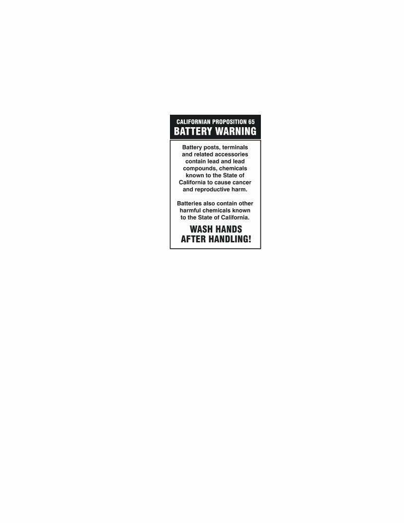

JLG Worldwide Locations
Corporate Office
JLG Industries, Inc.
1 JLG Drive
McConnellsburg PA. 17233-9533
USA
Phone: (717) 485-5161
Fax: (717) 485-6417
JLG Industries (Australia)P.O. Box 511911 Bolwarra RoadPort MacquarieN.S.W. 2444AustraliaPhone: (61) 2 65 811111Fax: (61) 2 65 810122
JLG Industries (UK)Unit 12, SouthsideBredbury Park Industrial EstateBredburyStockportSK6 2sPEnglandPhone: (44) 870 200 7700Fax: (44) 870 200 7711
JLG Deutschland GmbHMax Planck Strasse 21D-27721 Ritterhude/lhlpohlBei BremenGermanyPhone: (49) 421 693 500Fax: (49) 421 693 5035
JLG Industries (Italia)Via Po. 2220010 Pregnana Milanese - MIItalyPhone: (39) 02 9359 5210Fax: (39) 02 9359 5845
JLG Latino Americana Ltda.Rua Eng. Carlos Stevenson,80-Suite 7113092-310 Campinas-SPBrazilPhone: (55) 19 3295 0407Fax: (55) 19 3295 1025
JLG Europe B.V.Jupiterstraat 2342132 HJ FoofddorpThe NetherlandsPhone: (31) 23 565 5665Fax: (31) 23 557 2493
JLG Industries (Norge AS)Sofeimyrveien 12N-1412 SofienyrNorwayPhone: (47) 6682 2000Fax: (47) 6682 2001
JLG PolskaUI. Krolewska00-060 WarsawaPolandPhone: (48) 91 4320 245Fax: (48) 91 4358 200
JLG Industries (Europe)Kilmartin Place, Tannochside ParkUddingston G71 5PHScotlandPhone: (44) 1 698 811005Fax: (44) 1 698 811055
JLG Industries (Pty) Ltd.Unit 1, 24 Industrial ComplexHerman StreetMeadowdaleGermistonSouth AfricaPhone: (27) 11 453 1334Fax: (27) 11 453 1342
Plataformas Elevadoras JLG Iberica, S.L.Trapadella, 2P.I. Castellbisbal Sur08755CastellbisbalSpainPhone: (34) 93 77 24700Fax: (34) 93 77 11762
JLG Industries (Sweden)Enkopingsvagen 150Box 704SE - 175 27 JarfallaSwedenPhone: (46) 8 506 59500Fax: (46) 8 506 59534


