MaintenanceThis emergency lighting unit should be tested and maintained in accordance with National Electrical Code and NFPA 101 Life Safety Code requirements. It is recommended that emergency light fixtures be tested for 30 seconds once a month and for 90 minutes once a year.
Taking A Unit Out of ServiceIf a unit is to be deliberately taken out of service for an extended period, the battery lead connector should be disconnected from the charger circuit board and insulated so that the battery will go into storage in a fully charged condition.
Replacing the Battery:1. De-energize the AC power.2. Remove the front housing cover.3. Disengage the battery and heater (if provided) harness from the charger PCB harness.4. Disconnect the battery strap and remove battery pack.5. Replace with new battery (see unit model label or battery label for correct p/n) and repeat steps above in reverse.
Replacing LED LampsThe LED lamp heads are field replaceable. Please see Dual-Lite.com for further assistance.
TroubleshootingEmergency circuit does not work• Batteries are shipped uncharged, please charge for 24 hours before testing.• Make sure the switch pcb and the button/light pipe is correctly seated and aligned.• Check wiring connections.
0603638
INSTALLATION
This Industrial Unit is designed to be mounted on a wall, ceiling or pole (optional). Provide standard units with a single unswitchedpower supply from a 120 - 277VAC branch circuit used for normal lighting in the areas to be protected. For Spectronself-testing/self diagnostic units, provide unit with a 120/277VAC branch circuit.
The DYN Industrial unit is equipped with intelligent wiring. Connect the black wire from unit to the building hot wire (120 or 277VAC) and the white wire to the building com wire. (Exceptions: All Non-Spectron models should be connected to 120, 240 or 277VAC supplies only.)
WARNING- This product contains chemicals known to the State of Califorina to cause cancer, birth defects, and/or other reproductive harm. Thoroughly wash hands after installing, cleaning, or otherwire touching this product.
Initiating Action Test Cycle Press test switch once 1 minute Press test switch twice 90 minutes
Manual TestsUsing the unit test switch, users can initiate different duration test cycles based on the following table:
Pressing the test switch any time after a 90 minute test cycle has begun cancels the remainder of the 90 minute test and returns the unit to normal operation.
Testing Period Duration of Test Once a month 1 minute Once every Alternating: 6 months 30 minutes or 60 minutes
Automatic TestsThe unit will automatically initiate a self-test/self-diagnostic cycle based on the following table:
93052054
LED Status Indicator:A green/red LED is provided on the control paneof all models equipped with the Spectron option.
Green Operating Status LED:The green Operating Status LED serves as both an AC power and self-test indicator. During normal operation, the green Operating Status LED will be illuminated, indicating the presence of AC power. During all automatic or manual self-test cycles, the green Operating Status LED will blink “twice” per second for the 30 / 60 / 90 minute test.
Red Service Alert LED:Under normal operating conditions, the red Service AlertLED indicator will remain off. If the Spectron controllerdetects a malfunction, the red Service Alert LED will blinkin the pattern listed on the label around the test button.
= LAMP FAULT = LED DRIVER FAULT
= CHARGER FAULT = BATTERY FAULT
= BATTERY DISCONNECTED
SERVICE ALERT CODES
ALTERNATING = LOAD LEARN IN PROGRESS = LOAD LEARN FAILURE
OPERATION
ALBALBEC-1210170035/31/131
4 3 2 1
AAA
B
4 3 2 1
A
B
This document contains confidential and proprietary information of Dual Lite.Receipt or possession of this document does not convey any rights toreproduce or disclose its contents, or to make, use , or sell anything it maydisclose. Reproduction, disclosure, or use of the document or its contents,without the specific written authorization of Dual Lite, may violate theintellectual property rights of Dual Lite.
THIS ILLUSTRATION IS USED ON INSTRUCTION SHEET 93048898
ALBALBEC-1210170035/31/131
4 3 2 1
AAA
B
4 3 2 1
A
B
This document contains confidential and proprietary information of Dual Lite.Receipt or possession of this document does not convey any rights toreproduce or disclose its contents, or to make, use , or sell anything it maydisclose. Reproduction, disclosure, or use of the document or its contents,without the specific written authorization of Dual Lite, may violate theintellectual property rights of Dual Lite.
INSTALLATION INSTALLATIONWall, Ceiling or Pole Mounting
Pole Mounting
1. Loosen the three captive screws on the Food Processing clear cover.2. Remove cover. (all models without clear cover skip step 1 & 2)3 Rotate lamp heads to desired position.4. Loosen set screws 2 per head and adjust axially on stem.5. Lock set screws once desired position is set (hex wrench provided).6. Reverse steps 2 &1 (if required).
NOTE: IF UNIT IS IN A WET LOCATION ENVIRONMENT, ALL COVER SCREWS ARE TO BE TORQUED TO 5-6 INCH POUNDS OR UNTIL COVER SEATS WITH HOUSING!“DO NOT OVER TIGHTEN SCREWS” 7X PLCS
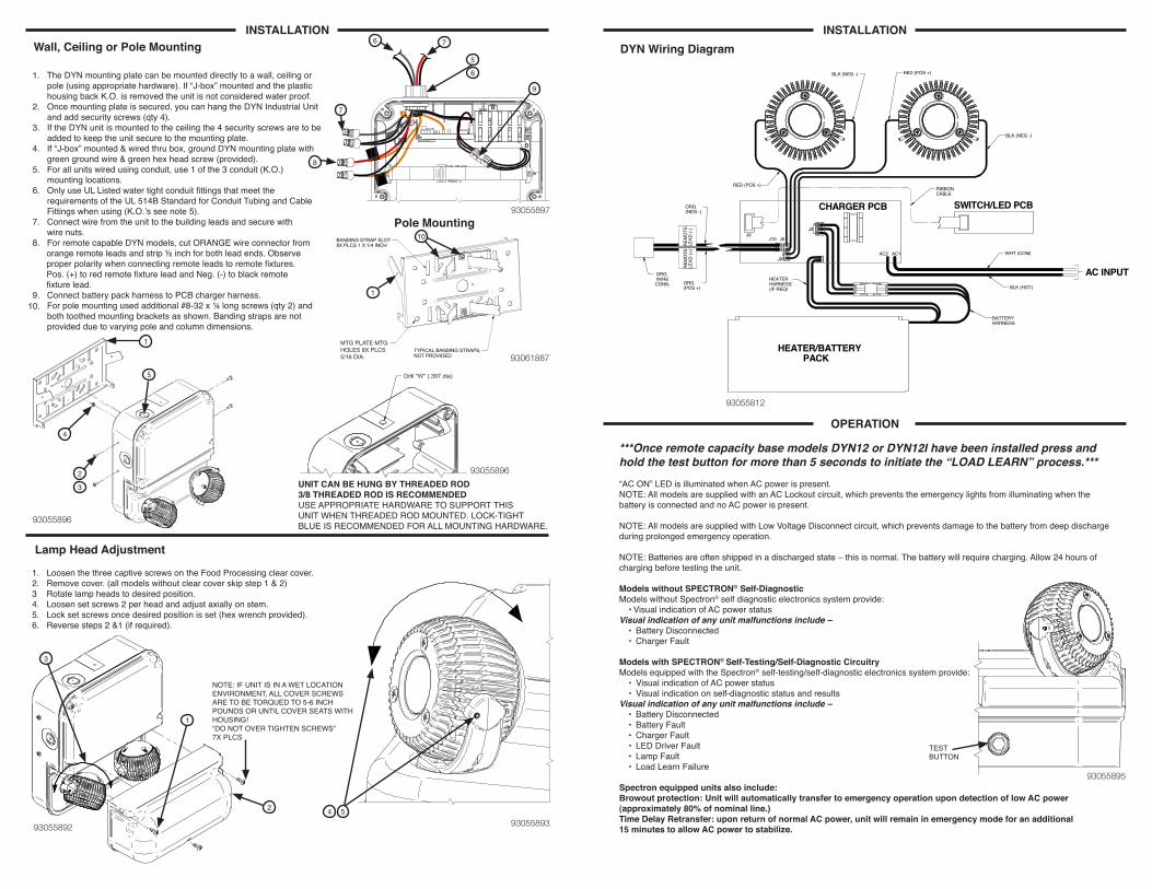
DYN Wiring Diagram
Lamp Head Adjustment
93055897
93061887
93055896
93055892 93055893
93055896
93055812
***Once remote capacity base models DYN12 or DYN12I have been installed press and hold the test button for more than 5 seconds to initiate the “LOAD LEARN” process.***“AC ON” LED is illuminated when AC power is present.NOTE: All models are supplied with an AC Lockout circuit, which prevents the emergency lights from illuminating when the battery is connected and no AC power is present.
NOTE: All models are supplied with Low Voltage Disconnect circuit, which prevents damage to the battery from deep discharge during prolonged emergency operation.
NOTE: Batteries are often shipped in a discharged state – this is normal. The battery will require charging. Allow 24 hours of charging before testing the unit.
Models without SPECTRON® Self-DiagnosticModels without Spectron® self diagnostic electronics system provide: • Visual indication of AC power status Visual indication of any unit malfunctions include – • Battery Disconnected • Charger Fault
Models with SPECTRON® Self-Testing/Self-Diagnostic CircuitryModels equipped with the Spectron® self-testing/self-diagnostic electronics system provide: • Visual indication of AC power status • Visual indication on self-diagnostic status and resultsVisual indication of any unit malfunctions include – • Battery Disconnected • Battery Fault • Charger Fault • LED Driver Fault • Lamp Fault • Load Learn Failure
Spectron equipped units also include:Browout protection: Unit will automatically transfer to emergency operation upon detection of low AC power (approximately 80% of nominal line.)Time Delay Retransfer: upon return of normal AC power, unit will remain in emergency mode for an additional 15 minutes to allow AC power to stabilize.
OPERATION
1. The DYN mounting plate can be mounted directly to a wall, ceiling or pole (using appropriate hardware). If “J-box” mounted and the plastic housing back K.O. is removed the unit is not considered water proof.2. Once mounting plate is secured, you can hang the DYN Industrial Unit and add security screws (qty 4).3. If the DYN unit is mounted to the ceiling the 4 security screws are to be added to keep the unit secure to the mounting plate.4. If “J-box” mounted & wired thru box, ground DYN mounting plate with green ground wire & green hex head screw (provided).5. For all units wired using conduit, use 1 of the 3 conduit (K.O.) mounting locations.6. Only use UL Listed water tight conduit fittings that meet the requirements of the UL 514B Standard for Conduit Tubing and Cable Fittings when using (K.O.’s see note 5).7. Connect wire from the unit to the building leads and secure with wire nuts.8. For remote capable DYN models, cut ORANGE wire connector from orange remote leads and strip ½ inch for both lead ends. Observe proper polarity when connecting remote leads to remote fixtures. Pos. (+) to red remote fixture lead and Neg. (-) to black remote fixture lead.9. Connect battery pack harness to PCB charger harness.10. For pole mounting used additional #8‐32 x ¼ long screws (qty 2) and both toothed mounting brackets as shown. Banding straps are not provided due to varying pole and column dimensions.
UNIT CAN BE HUNG BY THREADED ROD3/8 THREADED ROD IS RECOMMENDEDUSE APPROPRIATE HARDWARE TO SUPPORT THISUNIT WHEN THREADED ROD MOUNTED. LOCK-TIGHTBLUE IS RECOMMENDED FOR ALL MOUNTING HARDWARE.
DO NOT SCALE PRINTCONFORMS TO ASME Y14.5MDIMENSIONS IN [ ] IN MMDIMENSIONS IN INCHES
This document contains confidential and proprietary information of DualLite. Receipt or possession of this document does not convey any rights toreproduce or disclose its contents, or to make, use , or sell anything it maydisclose. Reproduction, disclosure, or use of the document or its contents,without the specific written authorization of Dual Lite, may violate theintellectual property rights of Dual Lite.
MATERIAL: FINISH: PART NO.
SCALE SIZE DRAWING NO. REV. SHT 11 SHTS
---
93055812
93055812
2
ILL-WIRING DIA DYNABrunelli 05/07/15
ALB 6/12/14
---
ALB 6/12/14
1:1
ALBEC-1210170036/12/141 ALB
---
ALBADDED WAGO ,EC-1210170035/7/152 ALB
THIS ILLUSTRATION IS USED ON INSTRUCTION SHEET 93048898
This document contains confidential and proprietary information of DualLite. Receipt or possession of this document does not convey any rights toreproduce or disclose its contents, or to make, use , or sell anything it maydisclose. Reproduction, disclosure, or use of the document or its contents,without the specific written authorization of Dual Lite, may violate theintellectual property rights of Dual Lite.
MATERIAL: FINISH: PART NO.
SCALE SIZE DRAWING NO. REV. SHT 11 SHTS
---
93055892
93055892
1
ILL-CLEAR CVR DYNALB 06/16/14
ALB 6/12/14
ALB 6/12/14
1:2
ALBEC-1210170036/12/141 ALB
---
THIS ILLUSTRATION IS USED ON INSTRUCTION SHEET 93048898
This document contains confidential and proprietary information of DualLite. Receipt or possession of this document does not convey any rights toreproduce or disclose its contents, or to make, use , or sell anything it maydisclose. Reproduction, disclosure, or use of the document or its contents,without the specific written authorization of Dual Lite, may violate theintellectual property rights of Dual Lite.
MATERIAL: FINISH: PART NO.
SCALE SIZE DRAWING NO. REV. SHT 11 SHTS
---
93055893
93055893
1
ILL-HD ADJ DYNALB 06/12/14
ALB 6/12/14
ALB 6/12/14
2:1
ALBEC-1210170036/12/141 ALB
---
THIS ILLISTRATION IS USED ON INSTRUCTION SHEET 93048898
This document contains confidential and proprietary information of DualLite. Receipt or possession of this document does not convey any rights toreproduce or disclose its contents, or to make, use , or sell anything it maydisclose. Reproduction, disclosure, or use of the document or its contents,without the specific written authorization of Dual Lite, may violate theintellectual property rights of Dual Lite.
MATERIAL: FINISH: PART NO.
SCALE SIZE DRAWING NO. REV. SHT 11 SHTS
---
93055895
93055895
1
ILL-TEST AC ON DYNALB 06/12/14
ALB 6/12/14
---
ALB 6/12/14
1:1
ALBEC-1210170036/12/141 ALB
---
THIS ILLISTRATION IS USED ON INSTRUCTION SHEET 93048898
This document contains confidential and proprietary information of DualLite. Receipt or possession of this document does not convey any rights toreproduce or disclose its contents, or to make, use , or sell anything it maydisclose. Reproduction, disclosure, or use of the document or its contents,without the specific written authorization of Dual Lite, may violate theintellectual property rights of Dual Lite.
MATERIAL: FINISH: PART NO.
SCALE SIZE DRAWING NO. REV. SHT 11 SHTS
---
93055897
93055897
1
ILL-WIRE ROUTING DYNALB 06/12/14
ALB 6/12/14
ALB 6/12/14
1:1
ALBEC-1210170036/12/141 ALB
---
THIS ILLISTRATION IS USED ON INSTRUCTION SHEET 93048898
This document contains confidential and proprietary information of DualLite. Receipt or possession of this document does not convey any rights toreproduce or disclose its contents, or to make, use , or sell anything it maydisclose. Reproduction, disclosure, or use of the document or its contents,without the specific written authorization of Dual Lite, may violate theintellectual property rights of Dual Lite.
MATERIAL: FINISH: PART NO.
SCALE SIZE DRAWING NO. REV. SHT 11 SHTS
---
3061887
93061887
1
ILL-POLE MTG DYNALB 03/02/15
ALB 6/12/14
---
ALB 6/12/14
1:1
ALBEC-12101700310/7/141 ALB
---
THIS ILLISTRATION IS USED ON INSTRUCTION SHEET 93048898
This document contains confidential and proprietary information of DualLite. Receipt or possession of this document does not convey any rights toreproduce or disclose its contents, or to make, use , or sell anything it maydisclose. Reproduction, disclosure, or use of the document or its contents,without the specific written authorization of Dual Lite, may violate theintellectual property rights of Dual Lite.
MATERIAL: FINISH: PART NO.
SCALE SIZE DRAWING NO. REV. SHT 11 SHTS
---
93055896
93055896
1
ILL-WALL MTG BRKTALB 06/12/14
ALB 6/12/14
---
ALB 6/12/14
1:2
ALBEC-1210170036/12/14 BLA1
---
THIS ILLISTRATION IS USED ON INSTRUCTION SHEET 93048898
Drill "W" (.397 dia)
UNIT CAN BE THREADED ROD MOUNTED3/8 THREADED ROD IS RECOMMENDED