To Suit Water Heater Models - Endurance 16 Endurance 20 Endurance 26 Endurance 32 Operation / Installation Manual Continuous flow water heaters This appliance shall be installed in accordance with:
Transcript
To Suit Water Heater Models - Endurance 16Endurance 20Endurance 26Endurance 32
Operation / InstallationManual
Continuous flow water heaters
This appliance shall be installed in accordance with:������������� ����������������������������������������������������������������������� ���!����"�#����������$������%���&���$��#���$�������$��#������'(�����)����*���+,����%%������*���.���������$��*�������$���$���*�/�$�.4������,�����$�5�����78���������$�����4����,����%%��������*���.���������$��%����$���$�*�������$�������$����9�,�,��*��������������������7
i Operation Manual - Dux Endurance Continuous Flow Hot Water®
PRODUCT RECORDS .............................................................................................25
OPERATION MANUAL
1 Operation Manual - Dux Endurance Continuous Flow Hot Water®
Your Dux Endurance Continuous Flow Water Heater has been certified by the Australian GasAssociation.The A.G.A. Certification Number is shown on the data plate.
This Appliance must be installed correctly by an authorised person. The installation of gas, water, andelectricity must conform to local regulations.
The installation must also comply with the instructions supplied by Dux.
All dimensions referred to in these instructions are in millimetres, unless otherwise specified.
Please keep this instruction booklet in a safe place for future reference.
Notice to Victorian Consumers
This appliance must be installed by a person licensed with the Plumbing Industry Commission.
Only a licensed person will have insurance protecting their workmanship.
So make sure you use a licensed person to install this appliance and ask for your ComplianceCertificate. For Further information contact the Plumbing Industry Commission on 1800 015 129.
Heated water can be dangerous, especially for youngchildren and the infirm.
Water temperatures above 50°C can cause severe burnsinstantly and may even result in death.
Those most at risk are children, disabled, elderly and theinfirm.
Hot water at 65°C (a very common hot water temperature inAustralia) can severely burn a child in less than half a second.At 50°C it takes five minutes.
ALWAYS......
Test the temperature of the water with your elbow before placing your child in the bath, alsocarefully feel water before bathing or showering yourself.
Supervise children whenever they are in the bathroom.
Make sure that the hot water tap is turned off tightly.
CONSIDER.....
Installing child proof tap covers or child resistant taps (both approaches will prevent a smallhand being able to turn on the tap).
Setting your appliance at a maximum temperature of 50°C (Contact Dux).
NEVER…..
Leave a toddler in the care of another child. They may not understand the need to have thewater temperature set at a safe level.
REGULATORY INFORMATION
WARNING ABOUT HOT WATER
FEATURES AND BENEFITS
Congratulations on purchasing the latest technology temperature controlled Dux EnduranceContinuous Flow Water Heating system.
• The Dux Endurance Continuous Flow Water Heater products NEVER RUN OUT of hot water. Whilstelectricity, water and gas supplies are connected, hot water is available whenever hot water taps areopen.
• Built into the main micro-processor is the facility to LIMIT THE MAXIMUM TEMPERATURE of thehot water supplied. The water temperature may be limited to various values. This is particularlyuseful when the hot water unit is installed where young children or the infirm may be using the hotwater.
• The Dux Endurance Continuous Flow Water Heater products are power flued appliances. Thismakes them COMPACT, saving both floor and wall space.
• The temperature of hot water is CONSTANTLY MONITORED by a BUILT-IN SENSOR. If thetemperature of the hot water rises to more than 3°C above the selected temperature the burner isturned OFF and only turned ON again when the temperature falls below the selected temperature.
• The burner lights automatically when the hot water tap is opened, and goes out when the tap isclosed. IGNITION IS ELECTRONIC, so there is no pilot light. When the hot water tap is off, no gas isused.
• The "Readyhot" system when fitted can pre-heat the water in the pipe-work between the waterheater and the hot water outlets. This results in water savings and reduces waiting time for heatedwater at the outlets.
• Operating NOISE LEVEL IS VERY LOW.
• ERROR MESSAGES ARE DISPLAYED on the Water Controllers assisting with service.
®
2 Operation Manual - Dux Endurance Continuous Flow Hot Water®
IMPORTANT INFORMATION
Always check water temperature carefully beforeuse. Refer to the WARNING ABOUT HOT WATERon "page 1" of this manual for important safetyinformation.
At low water flows, the hot water unit may extinguishwithout warning. Opening the tap further will restartthe appliance.
Do Not touch the unit cover or the flue outlet.Do Not insert objects into the flue outlet.
On colder days steam may discharged from the flueoutlet. This condition is normal for high efficiencyappliances and does not indicate a fault.
Keep flammable materials, spray cans, fuelcontainers, pool chemicals, trees, shrubs, etc. wellclear of the flue outlet.
Do Not spray water directly into the flue terminal.
If freezing conditions are expected, turn off water andgas and drain all water from the appliance. If powerand the automatic frost protection are connected,freezing will be prevented. (Anti-frost protection isfitted as standard equipment ).
The delivered water temperature is controlledautomatically. The flow may vary depending on thedelivery temperature selected and the ambient watertemperature.
OFF!
HOT!
Filter
Drain
GasValve
GasColdHot
Turn Water Off
Turn Gas Off
Drain Water
43°C 55°C
3 Operation Manual - Dux Endurance Continuous Flow Hot Water®
IMPORTANT INFORMATION
To clean your water controller(s) use a softdamp cloth with a mild detergent.
Do Not use solvents!
Whilst hot water outlets are open the settemperature may be lowered. However theycannot then be raised above 43°C. In additiontransfer of 'priority' between controllers is notpossible. These are safety features.
Depending on the weather conditions and thelength of the pipe between the hot water unitand the outlet in use, there may be a variationbetween the temperatures displayed at thewater controller(s) and the temperature of thewater at the outlet.
There is no need to turn the water controller(s)off after use. However, if you prefer to turn thewater controller(s) off, selected temperaturesto a maximum of 50°C will be stored in thesystem memory at all times whilst mains powerremains connected.
As a safety precaution, if a Kitchen Controller'stemperature is set above 50°C, transferringand then returning 'priority' to the KitchenController will result in a default settemperature of 50°C being selected. This is asafety feature.
Do Not push the On/Off button on anyController when the ‘Red’ water heater ‘In Use’indicator is illuminated as this will turn off thewater heater causing the water to go cold.Someone maybe in the middle of having ashower or filling a bath.
SOLVENT
Max.43°C
49°C
50°C
Kitchen Kitchen
Bathroom
4 Operation Manual - Dux Endurance Continuous Flow Hot Water®
OPERATION WITHOUT CONTROLLERS
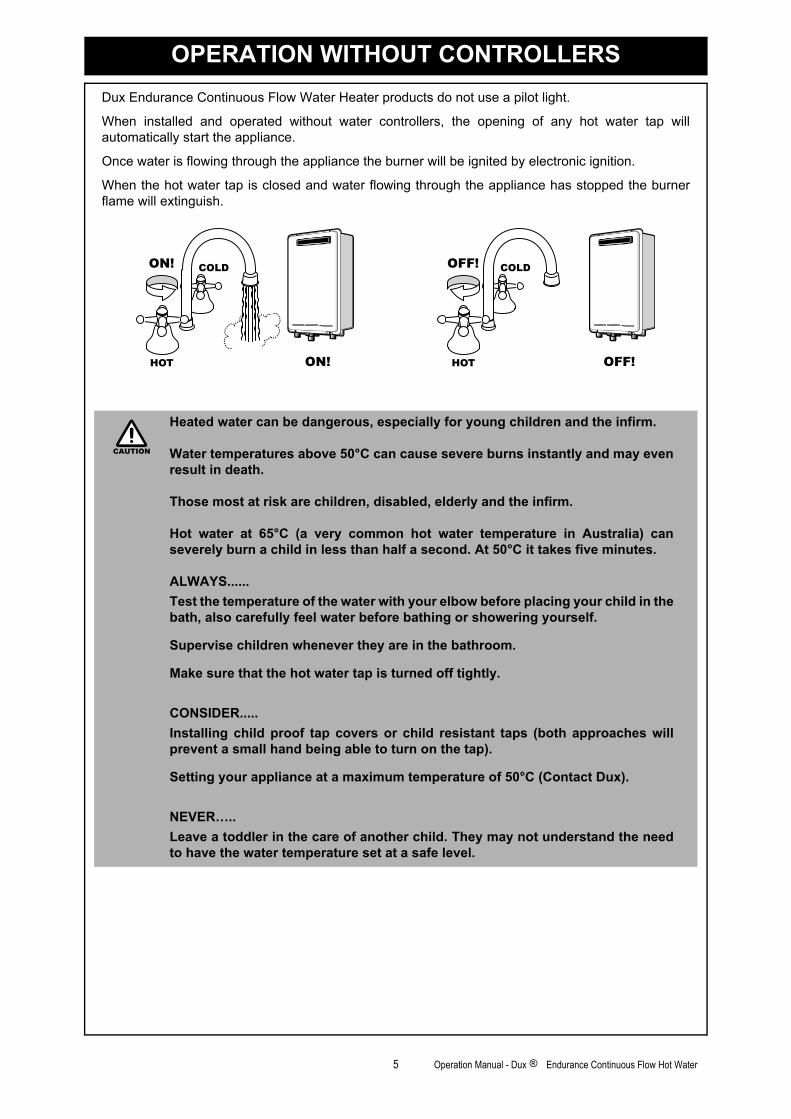
Dux Endurance Continuous Flow Water Heater products do not use a pilot light.
When installed and operated without water controllers, the opening of any hot water tap willautomatically start the appliance.
Once water is flowing through the appliance the burner will be ignited by electronic ignition.
When the hot water tap is closed and water flowing through the appliance has stopped the burnerflame will extinguish.
Heated water can be dangerous, especially for young children and the infirm.
Water temperatures above 50°C can cause severe burns instantly and may evenresult in death.
Those most at risk are children, disabled, elderly and the infirm.
Hot water at 65°C (a very common hot water temperature in Australia) canseverely burn a child in less than half a second. At 50°C it takes five minutes.
ALWAYS......
Test the temperature of the water with your elbow before placing your child in thebath, also carefully feel water before bathing or showering yourself.
Supervise children whenever they are in the bathroom.
Make sure that the hot water tap is turned off tightly.
CONSIDER.....
Installing child proof tap covers or child resistant taps (both approaches willprevent a small hand being able to turn on the tap).
Setting your appliance at a maximum temperature of 50°C (Contact Dux).
NEVER…..
Leave a toddler in the care of another child. They may not understand the needto have the water temperature set at a safe level.
HOTHOT
COLDCOLDON!ON!
ON!ON! HOTHOT
COLDCOLDOFF!OFF!
OFF!OFF!
CAUTION
5 Operation Manual - Dux Endurance Continuous Flow Hot Water®
GENERAL WATER CONTROL INFORMATION
MAXIMUM DELIVERY TEMPERATURES
Dux Endurance Continuous Flow Water Heaters are factory pre-set to various maximum deliverytemperatures depending on model and their intended application. For the majority of applications, thefactory pre-set temperature is appropriate. In the unlikely event this is not the case this setting can beincreased or decreased by an authorised person such as a licensed plumber.
Factory pre-set delivery temperatures for the various models are as follows:
This does not apply to “50 degree compliant” models. To meet the regulatoryrequirements for these models, the maximum delivery temperature is factory setand sealed.
Model Name Appliance DataPlate Codes
Factory “pre-set”Maximum Delivery Temperature (°C)
Can The Factory“Pre-Set” Maximum
Delivery TemperatureBe Changed By An
Authorised Person?
Endurance 16 DEU-VR1620WG-AK 60 Yes
Endurance 20 DEU-VR2024WG-AK 60 Yes
Endurance 26 DEU-VR2626WG-AK 60 Yes
Endurance 32 DEU-VR3237WG-AK 60 Yes
Endurance 16 - 50°C Compliant DEU-VR1620WG(50)-AK 50 No
Endurance 20 - 50°C Compliant DEU-VR2024WG(50)-AK 50 No
Endurance 26 - 50°C Compliant DEU-VR2626WG(50)-AK 50 No
Endurance 32 - 50°C Compliant DEU-VR3237WG(50)-AK 50 No
NOTE
6 Operation Manual - Dux Endurance Continuous Flow Hot Water®
GENERAL WATER CONTROL INFORMATION
Water controllers allow precise temperature control by the user. When used correctly, the hot waterunit will deliver the selected temperature, even when the water flow is varied, or more than one tap isin use. Each water controller can be individually programmed, however the water heater can onlydeliver one set temperature at any time. The available temperatures (°C) are as follows:
Whilst hot water outlets are open the set temperature may be lowered. However the set temperaturecannot then be raised above 43°C. In addition, transfer of 'priority' between water controllers is notpossible. These are safety features.
* Temperature may not be available refer to “Delivery Temperatures”.
These temperatures are suggestions only. You may find higher or lower temperatures morecomfortable. Maintaining lower temperatures helps save energy. To obtain water temperatures lowerthan 37°C simply add cold water.
Water controllers allow the water temperature to be set from the various locations where they areinstalled. The temperature selected will be available to all outlets.
7 Operation Manual - Dux Endurance Continuous Flow Hot Water®
WATER CONTROLLERS
ABOUT THE WATER CONTROLLER
TURNING ON THE CONTROLLER
If the water controller is switched off (No digits displayed in thedigital monitor window) press the On/Off button once.
The ON indicator will illuminate, indicating that the hot water unitwill be ready to supply hot water once a hot water tap is opened.
ADJUSTING TEMPERATURE
Select the desired temperature using the 'Hot water temp' or buttons until the required temperature is displayed on the
digital monitor.
To operate the hot water unit, open any hot water tap. This willautomatically light the burner providing hot water. The waterheater ‘In Use’ indicator will illuminate on the water controller.
Once the hot water is running, if the set temperature is either toohot or cold press the 'Hot water temp' or buttons until thedesired temperature is reached. (Refer to the Note Warningbelow).
CHECK WATER TEMPERATURE BEFORE USE.A parent or carer should always check the temperature before a child is placedin contact with hot water, see page 1.
Whilst hot water outlets are open the set temperature may be lowered. Howeverthey cannot then be raised above 43°C. In addition, transfer of 'priority' betweencontrollers is not possible. These are safety features.
The 'beep' sound can be muted by pressing the 'Hot water temp' Up andDown buttons simultaneously for more than 3 seconds.
I n d i c a t es t h e te m p e r a t u reselected. Error message flash inevent of a fault.
DIGITAL MONITOR
Used to select water temperature.
TEMPER ATURECONTRO L BUTTONS
Indicates if this temperaturecontroller is in control of waterdelivery temperature.
CONTROLLERON INDICATOR
Indicates that the Readyhot ®
p r e h e a t er ( w h e n f i t t e d ) i sactivated.
PREHEAT INDICATOR
Used to switch the water heateron and off.
ON/OFF BUTTON
Used to start and stop theReadyhot preheat unit (whenfitted), See Readyhot ® operationon page 10.
PREHEAT BUTTON
Used to transfer control priorityb e t w e e n t h e t e m p e r a t u r econtrollers. The controller withpriority has command of the hotwater delivery temperature.
TRANSFER BUTTON
Indicates that a water heater is inoperation and delivering hotwater.
WATER HEATER'In Use' INDICATOR
HOTHOT
COLDCOLDON!ON!
CAUTION
NOTE
8 Operation Manual - Dux Endurance Continuous Flow Hot Water®
WATER CONTROLLERS
HOW TO USE TWO OR MORE WATER CONTROLLERS
TURNING ON THE CONTROLLERS
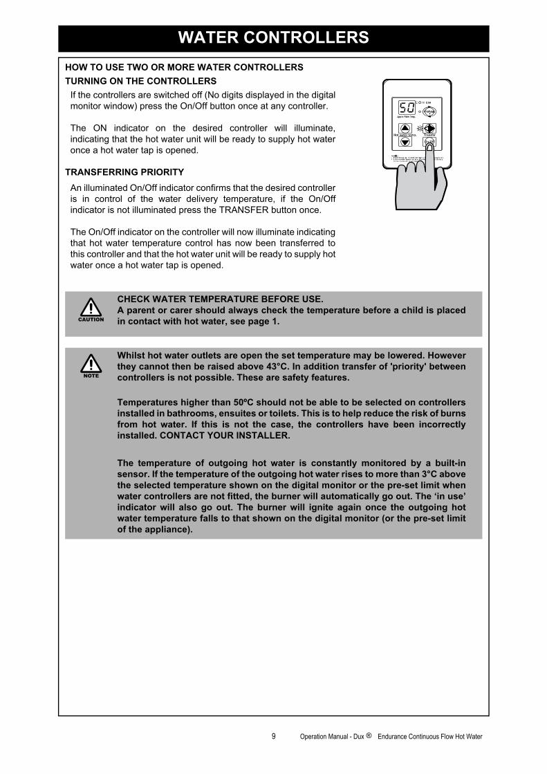
If the controllers are switched off (No digits displayed in the digitalmonitor window) press the On/Off button once at any controller.
The ON indicator on the desired controller will illuminate,indicating that the hot water unit will be ready to supply hot wateronce a hot water tap is opened.
TRANSFERRING PRIORITY
An illuminated On/Off indicator confirms that the desired controlleris in control of the water delivery temperature, if the On/Offindicator is not illuminated press the TRANSFER button once.
The On/Off indicator on the controller will now illuminate indicatingthat hot water temperature control has now been transferred tothis controller and that the hot water unit will be ready to supply hotwater once a hot water tap is opened.
CHECK WATER TEMPERATURE BEFORE USE.A parent or carer should always check the temperature before a child is placedin contact with hot water, see page 1.
Whilst hot water outlets are open the set temperature may be lowered. Howeverthey cannot then be raised above 43°C. In addition transfer of 'priority' betweencontrollers is not possible. These are safety features.
Temperatures higher than 50ºC should not be able to be selected on controllersinstalled in bathrooms, ensuites or toilets. This is to help reduce the risk of burnsfrom hot water. If this is not the case, the controllers have been incorrectlyinstalled. CONTACT YOUR INSTALLER.
The temperature of outgoing hot water is constantly monitored by a built-insensor. If the temperature of the outgoing hot water rises to more than 3°C abovethe selected temperature shown on the digital monitor or the pre-set limit whenwater controllers are not fitted, the burner will automatically go out. The ‘in use’indicator will also go out. The burner will ignite again once the outgoing hotwater temperature falls to that shown on the digital monitor (or the pre-set limitof the appliance).
CAUTION
NOTE
9 Operation Manual - Dux Endurance Continuous Flow Hot Water®
10 Operation Manual - Dux Endurance Continuous Flow Hot Water®
READYHOT PRE-HEAT OPERATION
ABOUT THE READYHOT PREHEAT SYSTEM
Preheat Function
The “Preheat” function works in conjunction with the various Dux Endurance models and theseparately installed and optional Dux “Readyhot” module.
When the “Preheat” function is activated and used in accordance with these instructions, water in thepipework connected between the water heater and the hot water outlets in your house is warmedbefore any outlets are opened. This results in water savings and added convenience.
The “Preheat” function is activated as follows:
1. Ensure that the hot water unit is on (temperature digits are displayed in the digital monitor ).If more than one controller is fitted press the ‘Transfer’ button to pass on priority to yourdesired controller, the ‘Controller On’ indicator will illuminate to confirm that priority has beenassigned to this controller and that the hot water unit is ready to deliver hot water.
2. Select the desired temperature using the 'Temperature' buttons until the requiredtemperature is displayed in the digital monitor .
3. Press the ‘Preheat’ button once. The ‘Preheat’ indicator and the ‘In Use’ indicatorswill illuminate, signifying that the preheat system has been activated.
4. Wait approximately two minutes before opening an outlet. This will allow the water in thepipework to be warmed.
Other Controller Functions
Controller functions such as temperature control and transfer of priority between multiple controllersis not affected by the operation of the preheat. Such functions are described in the applicable sectionsof this manual.
The waiting time may be longer or shorter than two minutes depending on yourparticular installation configuration.
The “Preheat” function is cancelled 5 minutes after activation and the ‘Preheat’indicator will go out. This is to conserve energy. To reactivate, simply repeatsteps 2-4 above.
* If the ‘Preheat’ button is pressed and the ‘Readyhot’ preheat unit is not installed,the ‘Preheat’ indicator will still light but there will be no “Preheat” function. The‘Preheat’ indicator will go out after a short time and will not affect the otherfunctions of the water controller or water heater.
DIGITALMONITOR
Indicates that 'Readyhot' preheater is activated*
PREHEAT INDICATOR2 3
ON/OFFBUTTON
4
CONTROLLER ONINDICATOR
5
TEMPERATUREBUTTONS
6
WATER HEATER'IN USE' INDICATOR
7
TRANSFERBUTTON
8Used to start and stop 'Readyhot' preheater.
PREHEAT BUTTON1
21
8
5
4
3 7
6
38
5
63
1 2 7
NOTE
11 Operation Manual - Dux Endurance Continuous Flow Hot Water®
TROUBLESHOOTING
Your Dux Endurance Continuous Flow Water Heaters has a self diagnostic capability. If a fault occurs,an Error Code will flash on the digital monitor if you have water controllers. This assists withdiagnosing the fault, and may enable you to overcome a problem without a service call. Please quotethe code displayed when enquiring about service.
In all cases, you may be able to clear the Error Code simply by turning the hot water tap OFF, then ON again. If this does not clear the Error Code,try pushing the On/Off button OFF, then ON again. If the Error Code still remains, contact Dux for advice.
Troubleshooting Without Controllers
If you have no water controllers and experience the following symptoms, carry out these suggestions.If the symptom continues, contact Dux for advice.
ERROR FAULT REMEDY
- Noticeable reduction in water flow. Inlet water filter needs to be cleaned. Service call.
03Power interruption during Bath fill
(Water will not flow on power reinstatement).Turn off all hot water taps. Press On/Off twice.
10 Air intake or flue blocked. Service Call.
11 No ignition / No gas supply.Check gas is turned on at water heater and gas meter
or cylinder.
12 Flame Failure / Low gas flow.Check gas is turned on at water heater
and gas meter or cylinder.Check there are no obstructions to the flue outlet.
14 Remaining Flame Safety Device. Service Call.
16 Over Temperature Warning. Service Call.
32 Outgoing Water Temperature Sensor Faulty. Service Call.
33 Heat Exchanger Outlet Sensor Faulty. Service Call.
34 Combustion Air Temperature Sensor Faulty. Service Call.
52 Gas Modulating Valve Faulty. Service Call.
61 Combustion Fan Failure. Service Call.
71 Micro-processor Failure. Service Call.
72 Micro-processor Failure. Service Call.
LC Scale build-up inside the heat exchanger. Service Call.
FAULT REMEDY
The unit does not attempt to start at all.Check the power is on at the unit.
Check the isolation valves at the unit are open.
The unit starts then shuts down immediately.
Check the power is still on.Check the gas isolation valves at theunit and the gas meter are fully open.
Open your hot water tap fully.
The unit starts then the water goes cold.Check the power is still on.
Open your hot water tap further.
Faults caused by insufficient gas supply, insufficient water supply, gas quality,water quality, installation errors or operation errors are not covered by the Duxwarranty. Refer to separate warranty booklet for details.NOTE
12 Operation Manual - Dux Endurance Continuous Flow Hot Water®
INTENTIONALLY BLANK PAGE
13 Operation Manual - Dux Endurance Continuous Flow Hot Water®
GENERAL INSTALLATION INSTRUCTIONS ..........................................................14
PRODUCT RECORDS .............................................................................................25
INSTALLATION MANUAL
GENERAL INSTALLATION INSTRUCTIONS
REGULATIONS
This appliance must be installed in accordance with:
• Current AS/NZS 3000, AS/NZS 3500 and AS/NZS 5601• Dux Installation Instructions• Local regulations and municipal building codes including local OH&S requirementsInstallation, Service and Removal MUST BE by an Authorised Person only.
APPLICABLE MODELS
These Installation Instructions apply only to the Dux Endurance Continuous Flow Water Heatermodels listed on page 6.
APPLIANCE LOCATION
This appliance is designed for ‘Outdoor’ Installation only. As such, it must be located in an aboveground open air situation with natural ventilation, without stagnant areas, where gas leakage andproducts of combustion are rapidly dispersed by wind and natural convection.
This appliance must be mounted on a vertical structure with the water and gas connections on theunderside pointing downwards. For appliances installed on elevated structures or under floors specificrequirements apply. Refer to AS/NZS 5601 Section 6 for details.
This appliance must not be used as a domestic spa or swimming pool heater.
Location of the appliance flue terminal must be in accordance with Section 6 and Figure 6.2 of AS/NZS 5601. Figure 6.2 is reproduced in the ‘Horizontal Flue Terminal Clearances’ section of theseinstructions. Note that AS/NZS 5601 was current at the time of printing but may have beensuperseded. It is the installers’ responsibility to ensure current requirements are met.
This appliance must be placed as close as practicable to the most frequently used hot water outlet oroutlets to minimise the delay time for hot water delivery. For installations where the distance betweenthe water heater and the outlets is considerable, a flow and return system or the Dux Readyhot systemcan be used which minimise the waiting time for hot water delivery.
Alternatively, multiple appliances can be strategically placed to serve outlets with minimal delay time.Contact Dux for further information.
An AC240V, 10 Amp, earthed power point must be provided adjacent to the appliance. For outdoorinstallations this power point must be weather proof. It must be clear of the gas and water connectionsto the appliance and also the flue exhaust and water pressure relief valve. The power cord of theappliance is 1.5 Metres long.
All appliances must be installed to ensure access can be gained without hazard or undue difficulty forinspection, repair, renewal or operational purposes. Sufficient clearances shall allow access to, andremoval of, all serviceable components. Appliances should not be mounted higher than 2.5 metresabove the ground or floor level unless the customer can arrange permanent and safe access or canprovide another means of access, for example, by means of scissor or boom lifts acceptable to localauthorities.
PIPE SIZING
See Table 1 page 16 for appliance gas consumption. If the gas pipe sizing is insufficient the customerwill not get the full performance benefit. Gas pipe sizing must consider the gas input to this applianceas well as all the other gas appliances in the premises. The gas meter and regulator must be specifiedfor this gas rate. An approved sizing chart such as the one in AS/NZS 5601 should be used.
Water pipe sizing and layout should be performed in accordance with AS/NZS 3500. All hot waterpipe-work should be insulated to optimise performance and energy efficiency.
WATER SUPPLY
See Table 1, page 16 for applicable water pressures. Approved pressure limiting valves may berequired if the ‘Maximum’ rated water supply pressures in Table 1 are exceeded. To achieve the ratedflow, the ‘Minimum’ water supply pressures in Table 1 must be supplied. The water heaters willoperate at lower pressures but will not achieve the rated flow. Contact Dux for ‘gravity fed’ or ‘lowpressure’ installations.
Water chemistry & impurity limits are detailed in separate Warranty booklet. Most metropolitan watersupplies fall within the requirements. If you are unsure about your local water quality, contact yourwater authority. If sludge or foreign matter is present in the water supply, a suitable filter or strainershould be incorporated in the water supply to the water heater.
14 Operation Manual - Dux Endurance Continuous Flow Hot Water®
GENERAL INSTALLATION INSTRUCTIONS
HOT WATER DELIVERY TEMPERATURE
Local regulations and or the requirements of AS/NZS 3500.4 must be considered regarding thetemperature limitations of hot water supplied to areas used primarily for personal hygiene. Thetemperature of water to these areas may be limited to 50º C or less. To ensure these regulations andor requirements are met the system MUST be installed in accordance with the 'Water Heater andController Installation Configurations' Section of these instructions.
WATER HEATER AND CONTROLLER INSTALLATION CONFIGURATIONS
If the appliance is marked to state that it delivers water not exceeding 50°C, local regulations maypermit it's installation without a Temperature Limiting Device. Installations without a TemperatureLimiting Device are shown in Diagram 1 (page 15). If you are unsure about your local regulationscontact your regulating authority or Dux.
If the appliance is NOT marked to state that it delivers water not exceeding 50°C, or your localregulations require installation with a Temperature Limiting Device then install the appliance inaccordance with Diagram 2 (page 15).
Ensure that suitable fixing screws or bolts are used to secure the units to the wall, in accordance withAS/NZS 5601 Section 5. Wooden plugs shall not be used.
The top bracket has a keyhole slot so that the appliance can be positioned by hanging it on one screw,then the other screws can be secured.
SERVICE CONNECTION POINTS
See Table 1 for individual appliance connection / fitting dimensions. Note that these dimensions areNOT an indication of the pipe sizes required.
An Approved full flow isolation valve and disconnection union MUST be fitted to the cold water inlet.A non return valve is not required unless required by local regulations.
Isolation Valves must not be fitted directly to the appliance.
If may be necessary to fit a temperature limiting device for delivery to areas used primarily for thepurposes of personal hygiene. Refer to the ‘Water Heater and Controllers Installation Configurations’Section of this document.
MOUNTING THE APPLIANCE
See Table 1, page 17 for individual appliance weights. The wall or structure on which the units areto be mounted must be capable of supporting these weights and the associated pipe-work.
The top bracket has a keyhole slot so that the appliance can be positioned by hanging it on onescrew, then the other screws can be secured.
The appliance can be mounted directly against the wall or structure. There is no need to use, noncombustible sheeting or leave an air gap between the appliance back panel and the wall or structurefor the purposes of meeting the temperature hazard requirements of AS/NZS 5601.
If the appliance is to deliver water primarily for the purposes of personal hygiene in anearly childhood centre, primary or secondary school, nursing home or a similar facilityfor the care of young, aged, sick or disabled persons as defined in AS/NZ 3500.4 aTemperature Limiting Device (TLD), such as a Tempering Valve may be required evenif the appliance is set to 50º C or less.
For these types of applications contact Dux.
IMPORTANT
50º C
KITCHEN
Water controller(optional)
Water controller(optional)
Water controller(optional)
Water controller(optional)
LAUNDRY
BATHROOM
ENSUITE
HOT
COLD
GAS
KITCHEN
Water controller(optional)
Water controller(optional)
LAUNDRY BATHROOM
Water controller(optional)
Water controller(optional)
ENSUITE
TLDHOT
COLD
GAS
Diagram 1 - 50°C Appliance Diagram 2 - Not a 50°C ApplianceNote: TLD = Temperature Limiting DeviceMinimum length of pipe from hot outlet
to nearest hot water tap 2 metres.
15 Operation Manual - Dux Endurance Continuous Flow Hot Water®
GENERAL INSTALLATION INSTRUCTIONS
Purge gas and cold water supply lines to remove air and swarf before final connection of theappliance. Swarf in either the gas or water supplies may cause damage.
Table 1.
Model:Gas
ConsumptionMJ/h
Water Supply kPaWeight
kg
Fittings
Min. Max. Hot Cold Gas
16 125 120 1000 15 R ½ (15mm) R ½ (15mm) R ¾ (20mm)
20 160 160 1000 15 R ¾ (20mm) R ¾ (20mm) R ¾ (20mm)
26 199 200 1000 16 R ¾ (20mm) R ¾ (20mm) R ¾ (20mm)
32 250 180 1000 29 R ¾ (20mm) R ¾ (20mm) R ¾ (20mm)
16 Operation Manual - Dux Endurance Continuous Flow Hot Water®
GENERAL INSTALLATION INSTRUCTIONS
HORIZONTAL FLUE TERMINAL CLEARANCES (Extract from AS/NZS 5601)
Flue terminal Fan assisted flue appliance only Gas meter Electricity meter or fuse box Mechanical air inlet
Natural draft Fan assisted
• Appliances up to 50 MJ/h input 300 200
• Appliances over 50 MJ/h input 500 300
b From the ground, above a balcony or other surface * 300 300
c Front a return wall or external corner * 500 300
d
From a gas meter (M) (see 5.11.5.9 for vent terminal location of regulator )
(see Table 6.6 for New Zealand requirements) 1000 1000
e From an electricity meter or fuse box (P) † 500 500
f From a drain pipe or soil pipe 150 75
g Horizontally from any building structure* = or obstruction facing a terminal 500 500
h From any other flue terminal , cowl, or combustion air intake † 500 300
• Appliances up to 150 MJ/h input * 500 300
• Appliances over 150 MJ/h input up to 200 MJ/h input * 1500 300
• Appliances over 200 MJ/h input up to 250 MJ/h input * 1500 500
• Appliances over 250 MJ/h input * 1500 1500
• All fan-assisted flue appliances , in the direction of discharge - 1500
k From a mechanical air inlet, including a spa blower 1500 1000
• Space heaters up to 50 MJ/hr input 150 150
• Other appliances up to 50 MJ/hr input 500 500
• Appliances over 50 MJ/h input and up to 150 MJ/h input 1000 1000
• Appliances over 150 MJ/h input 1500 1500
1 Where dimensions c, j or k cannot be achieved an equivalent horizontal distance
measured diagonally from the nearest discharge point of the terminal to the opening
may be deemed by the Technical Regulator to comply.
2 See Clause 6.9.4 for restrictions on a flue terminal under a covered area.
3 See Figure J3 for clearances required from a flue terminal to an LP Gas cylinder.A flue terminal is considered to be a source of ignition.
4
Ref. Item
a
Min. clearances (mm)
Below eaves, balconies and other projections:
j
Horizontally from an openable window, door, non-mechanical air inlet, or any other opening into a building
with the exception of sub-floor ventilation:
Vertically below an openable window, non-mechanical air inlet, or any other opening into a building with the
exception of sub-floor ventilation:
NOTES:† - Prohibited area below electricity meter or fuse box extends to ground level.
TERMINALS, ROOM-SEALED APPLIANCE TERMINALS AND OPENINGS OF OUTDOOR APPLIANCES
* - unless appliance is certified for closer installation
For appliance s not addressed above acceptance should be obtained from the Technical Regulator.
n
17 Operation Manual - Dux Endurance Continuous Flow Hot Water®
GENERAL INSTALLATION INSTRUCTIONS
HORIZONTAL OBSTRUCTIONS
AS/NZS 5601 ‘Gas Installations’ stipulates a minimumhorizontal clearance of 500 mm between a buildingstructure and obstruction facing the terminal. For Duxexternal continuous flow water heaters such a buildingstructure must ‘obstruct’ the full front cover height of theappliance, or extend vertically above and below the frontcover. There must be no partial obstructions to the frontcover of the appliance or any other parts of the appliancecasing. This will avoid the appliance failing to operateunder windy conditions.
MULTIPLE INSTALLATIONS OF EXTERNAL MODELS
Dimension ‘h’ above does not apply when multiple Duxexternal water heaters of the same model are installed onthe same vertical face with flue terminals at the sameheight. Under these conditions appliances can abut eachother as shown. The total gas consumption of allappliances applies when determining other clearances.
500mm
18 Operation Manual - Dux Endurance Continuous Flow Hot Water®
GENERAL INSTALLATION INSTRUCTIONS
APPLIANCE AND WATER CONTROLLER DIMENSIONS
D im ' D escrip tion
A W idth
B D epth
C H eight - U nit
D H eight - Inc lud ing B rackets
E H ot W ater outle t (from w all)
F H ot W ater outle t (from centre)
G C old W ater in le t (from w all)
H C old W ater in le t (from centre)
B
O
DC
K
1620
350
194
530
571
87
105
68
10
350
194
530
571
87
105
68
10
I G as C onnection (from w all)
J G as C onnection (from centre)
77
83
77
83
32
470
244
600
644
115
61
99
52
61
110
A
E
F
JH
I
G
* P lease note that th is m easurem ent is to the le ft o f the centre line.
P
QS
R
D im ' D escrip tion
P W idth
Q H eight
R D epth
S D istance betw een
m ounting hole centres
DMC-91Q-2A
90
120
20
83
26
350
194
530
571
87
105
68
10
77
83
Endurance Models
G as C onnection Length (from base)
C old C onnection Length (from base)
H ot C onnection Length (from base)
G as: F itting D iam eter
K
L
40
50
39
20
40
50
39
20
C old : F itting D iam eter
H ot: F itting D iam eter
41
51
42
20
20
20
15
15
20
20
40
50
42
20
20
20
19 Operation Manual - Dux Endurance Continuous Flow Hot Water®
WATER CONTROLLER INSTALLATION
WATER CONTROLLERS
Water controllers are available as an optional extra.
POSITIONING OF WATER CONTROLLERS
Water controllers must be installed in shaded and clean locations. They should be fitted out of reachof children (suggested height from floor to be at least 1500 mm).
WATER CONTROLLER CABLES
Water controllers operate at extra low voltage (12 Volts DC) which is supplied from the water heater.Each Water controller comes supplied with 15 m of electrical cable. The appliance end of the cablesare fitted with spade terminals. Extension cabling is available from Dux.
Other manufacturers water controllers are NOT compatible with Dux Endurancewater heaters.
Water controllers brought in from other countries are not compatible with Duxappliances sold in Australia.
• Do not install Water Controllers near a heat source, such as a cook top, stoveor oven. Heat, steam, smoke and hot oil may cause damage.
• Do not install remote controllers in direct sunlight.
• Do not install remote controllers outdoors unless protection from dustingress and sunlight are provided.
• Do not install remote controllers against a metal wall unless the wall isearthed in accordance with AS/NZS 3000.
• Water controllers MUST NOT be installed where chemicals such as benzine,alcohol, turpentine or other similar chemicals are in use.
POSITIONING CONSIDERATIONS FOR THE WATER CONTROLLER.
The water controller uses a Liquid Crystal Display (LCD) for thedigital monitor. Light reflections can make the LCD difficult tosee at direct eye level.
For best results when Installing the water controller mount lowerthan your eye-level to avoid these light reflections.
Alternatively two core sheathed (double insulated) flex with minimum cross-sectional area of 0.5 mm² may be used. Maximum individual cable runs shouldnot exceed 50 m.
FITTING THE WATER CONTROLLER
1. Determine the most suitable position for the water controller.
2. Mark and drill 3 holes, locating the cable access as shown in (Fig. 1).
3. When running cable through the access hole ensure the connector end of the cable is locatednearest to the controller (Fig.2).
4. Carefully remove face plate from the water controller, using a screw driver (Fig. 3).
5. Connect the cable to the water controller. Feed any excess cable lengths into the wall cavity toavoid the pinching of cables between the wall and the controller.
6. Fix the water controller to the wall using the appropriate fixings as shown in (Fig. 4).
NOTE
NOTE
NOTE
20 Operation Manual - Dux Endurance Continuous Flow Hot Water®
WATER CONTROLLER INSTALLATION
7. Remove protective film from the water controller face as shown in (Fig. 4) and replace face plate.
OPTIONAL PROGRAMMING FOR THE WATER CONTROLLER
Fig. 1 Fig. 2 Fig. 3 Fig. 4
Are there four water controllers connected ?
IF NO: (You have three water controllers or fewer), go to Question 2.
IF YES: You will need to activate the fourth water controller as follows:
STEP 1: For the water controller in the KITCHEN ONLY, press and holdthe ‘Transfer’ and ‘On/Off’ buttons simultaneously (see Fig. 5)until a ‘beep’ is heard (approximately 5 seconds).
STEP 2: Check that the display on ALL FOUR water controllers is lit anddisplaying a temperature when ‘switched on’. If any ONE of thecontroller displays two dashes (see Fig. 6) repeat STEP 1.
This completes the activation procedure for the fourth controller,you may ignore Question 2.
Fig. 5
Fig. 6
Is the water heater marked to state it delivers waternot exceeding 50°C ?
IF YES: No further action required.
IF NO: You will need to program the kitchen controller to enableselection of temperatures higher than 50°C.
STEP 1: For the controller in the KITCHEN ONLY, press and hold the‘Transfer’ and ‘On/Off’ buttons simultaneously (Fig. 7) until a‘beep’ is heard (approximately 5 seconds).
STEP 2: When the controller fitted in the KITCHEN is switched On, itshould be possible to select temperatures higher than 50°C. Ifnot, repeat STEP 1.
Fig. 7
If the water controller in the kitchen is replaced, repeat STEP 1 above for thereplacement controller.
If the water controller in the kitchen is swapped with another controller (forexample, the controller fitted in a bathroom), repeat STEP 1 for the controllermoved from the kitchen to the bathroom. Then perform STEP 1 for the controllermoved from bathroom to the kitchen.
8341
.5
120
Out
line
of W
ater
Con
trol
90S
ecur
ing
Scr
ew
Ø20
Cab
le A
cces
s
Connector
Controller CableFace Plate
Face Plate
Screw
Film
QUESTION
QUESTION
NOTE
21 Operation Manual - Dux Endurance Continuous Flow Hot Water®
WATER CONTROLLER INSTALLATION
CONNECTING COMMUNICATION CABLES TO THE WATER HEATER
Communication cables connect the water heater to water controllers and operate at an extra lowvoltage (12 Volts DC) which is supplied from the water heater. Communication cables are suppliedwith the water controllers (15m) and are fitted with spade terminals for connection to water heater. Upto two cables can be connected directly to the water heater. Extension cables are available from Dux.Alternatively, two core sheathed (double insulated) flex with minimum cross sectional area of 0.5mm²may be used. Cable lengths must not exceed 20 metres.
To connect up to two cables to the Water Heater
DO NOT attempt to connect cables to the water heater unless the electric power tothe water heater is switched ‘off’ otherwise damage to electrical components mayoccur.
1. Isolate the electric power supply by switching the power point off and removing the power plug ofthe water heater from the electric power socket.
2. Remove the retaining screw at the base of the appliance.
3. Swing the door open and thread the cable through the weather seal of the cable access hole in the direction shown allowing sufficient cable length so that the sheath of the cable can besecured with cable clamp supplied with the transceiver.
4. Loosen screw terminals and and connect the cable spade connectors to these terminalsand re-tighten. Polarity is not important, either wire colour can be connected to either terminal.
5. Return to the original position taking care not to damage cable wires in the process and replacethe retaining screw .
CAUTION
A
B
C
D E
A
A
B
A
CE
D
B
Suits Water Heater 16, 20, 26 Litre Models Suits Water Heater 32 Litre Model only
22 Operation Manual - Dux Endurance Continuous Flow Hot Water®
COMMISSIONING
TESTING
1. Before final connection of the water heater purge gas, hot water and cold water supply lines.Swarf in either the gas or water supplies may cause damage.
2. Turn on gas and cold water supplies.
3. Test for water leaks and gas escapes near the unit.
4. Isolate gas supply. Remove test point screw located on the gas inlet connection and attachpressure gauge.
5. Turn the power 'on' at the power point socket and turn on gas.
6. If water controllers are fitted, turn ensure they are controller 'ON', select the maximum deliverytemperature and open ALL available hot water taps including the shower. If remote controllersare not fitted, simply open all available hot water taps. (CAUTION: Ensure building occupants donot have access to hot water outlets during this procedure.)
7. Operate ALL other gas appliances at their maximum gas rate, in accordance with manufacturersinstructions.
8. With all gas appliances in operation at maximum gas rate, the pressure should read between1.13 - 3.0 kPa on Natural Gas. On LPG the pressure should be 2.75 - 3.0 kPa. If the pressure islower, the gas supply is inadequate and the appliance will not operate to specification. It is theInstallers responsibility to check the gas meter, service regulator and pipe work for correctoperation/sizing and rectify as required. Note that the gas regulator on the appliance iselectronically controlled and factory pre-set. Under normal circumstances it DOES NOT needadjustment during installation.
9. Close hot water taps including the shower.
10. Inspect and clean the strainer located on the cold water inlet connection. This procedure mayneed to be repeated to ensure the strainer remains clear, especially on new installations.
11. If water controllers are fitted, it is necessary to test their operation through the complete range offunctions (refer to the Operation sections of this manual).
12. Confirm the hot water delivery temperature(s) using a thermometer. If controllers are fitted,ensure temperatures exceeding 50°C cannot be selected on bathroom or ensuite controllers.Refer to the section ‘Delivery Temperature’ below for more details.
13. After testing is completed, explain to the householder the functions and operation of the waterheater and temperature controllers (if fitted). Ensure the “PRODUCT RECORDS” on page 25 ofthis manual is filled in and that the booklet is handed to the customer.
DELIVERY TEMPERATURE
"50°C Compliant" appliances are 'factory set' to deliver a maximum temperature not exceeding 50°C.However, they have an incremental adjustment mechanism that allows the installer to increase theappliance delivery temperature incrementally from the 'Factory Set’ value to temperatures exceeding50°C. This is intended to enable compensation for temperature losses in the pipe-work between thewater heater and any outlets and achieve the required temperature at the outlet. Instructions forincremental temperature adjustment are located in the instruction pocket inside the appliance frontcover.
For all other models Dux Endurance Continuous Flow Water Heaters are factory pre-set to various maximum deliverytemperatures depending on model and their intended application. For the majority of applications, thefactory pre-set temperature is appropriate. In the unlikely event it is not this setting can be increasedor decreased by the installer. Instructions for changing the maximum delivery temperature are locatedin the instruction pocket inside the appliance front cover.
23 Operation Manual - Dux Endurance Continuous Flow Hot Water®
COMMISSIONING
GAS PRESSURE SETTING
The regulator is electronically controlled and factory pre-set. Under normal circumstances it does notrequire adjustment during installation.
Make adjustments only if the unit is not operating correctly and all other possible causes for incorrectoperation have been eliminated.
Instructions for Gas Pressure Setting are to be found in the instruction pocket located inside theappliance front cover.
COMMISSIONING CHECK LIST
A commissioning check list is provided on the appliance front cover to enable the installer to stepthrough the correct commissioning procedure when installing a Dux Endurance Continuous FlowWater Heater.
The check list can also assist the installer to identify potential installation errors that may prevent theappliance from operating correctly.
24 Operation Manual - Dux Endurance Continuous Flow Hot Water®
25 Operation Manual - Dux Endurance Continuous Flow Hot Water®
ACCESSORIES
Recess Box (RBP1):
These allow the appliance to be recessed into the cavity of the wall saving precious space. Suitable for painting.
Contact Dux for further information about our accessory range and model suitability details.
Please take a moment to record the following information below for your own records.
Model No : Serial No :
Your Retailer :
Address :
Contact Number: ( )
Purchase Date : / /
Your Installer :
Address :
Installers License No. :
Contact Number : ( )
Installation Date : / /
Certificate of Compliance No. :
PRODUCT RECORDS
26 Dux Endurance Cont. Flow HW - 11-007 Version 2 - 8/8/11®
Head OfficeLackey RoadMoss Vale NSW 2577 Australia
Tel: 1300 365 115 (Australia)Tel: 0800 729 389 (New Zealand)
For advice, repairs and service, call: 1300 365 115 (Australia)0800 729 389 (New Zealand)
Manufacturing Limited ABN 19 077 879 844 Internet: www.dux.com.au
Dux has a Service and Spare Parts network with personnel who are fully trained and equipped to give the best service on your appliance. If your appliance requires service, please call. We recommend that this appliance be serviced every 3 years.


![[Game Master] Gaming on Windows 10 - Troubleshooting if you’re · 2018-12-16 · [Game Master] Gaming on Windows 10 - Troubleshooting This document supplies you with useful solutions](https://static.documents.pub/doc/80x56/5f0eb0cf7e708231d4407608/game-master-gaming-on-windows-10-troubleshooting-if-youare-2018-12-16-game.jpg)

