0 26-09-2014 First Submission Rev No. Issue Date Description Remarks OPERATION & MAINTENANACE MANUAL Client Name Bayer Vendor Name Hydropure Systems & Exergy LLC Item Point of Use Cooler Capacity 5 GPM Document Name Operation & Maintenance Manual Document No. HPS-PR247-O&M-001 Total No. of Pages 13
Transcript
0 26-09-2014 First Submission
Rev No. Issue Date Description Remarks
OPERATION & MAINTENANACE MANUAL
Client Name Bayer
Vendor Name Hydropure Systems & Exergy LLC
Item Point of Use Cooler
Capacity 5 GPM
Document Name Operation & Maintenance Manual
Document No. HPS-PR247-O&M-001
Total No. of Pages 13
Client Name Bayer Project Bayer Shawnee R&D
Item POU COOLER
Document Name Operation & Maintenance Manual
Document No. HPS-PR247-O&M-001 Rev No - 0
Issue Date 09/26/14 Page 2 of 13
TABLE OF CONTENTS
1.0 Safety and Design................................................................................. 3 1.1 Safety Precautions................................................................................ 3 1.2 Recycling Information........................................................................... 3 1.3 Application............................................................................................ 3 1.4 Design .................................................................................................. 4 2.0 Installation and Initial Start-Up.............................................................. 5 2.1 Installation Recommendations.............................................................. 5 2.2 The Pressure Drop Arrangement.......................................................... 7 2.3 Initial Start-Up Procedure...................................................................... 7 3.0 Operation.............................................................................................. 8 3.1 Stand-By Mode..................................................................................... 8 3.2 Cooling Mode....................................................................................... 8 3.3 Use of HMI Touchscreen…………....................................................... 8 3.4 Shut Down…………………………………………………………..……... 13 4.0 Maintenance.......................................................................................... 13 4.1 Cleaning of the Service Side ................................................................ 13 4.2 Steam-In-Place (SIP)............................................................................ 13 4.3 Gaskets................................................................................................. 13 4.4 Spare Part List……………….……………………….……….…………... 13 The information contained in this manual is for reference only and is subject to changes, if any, without prior notice.
Client Name Bayer Project Bayer Shawnee R&D
Item POU COOLER
Document Name Operation & Maintenance Manual
Document No. HPS-PR247-O&M-001 Rev No - 0
Issue Date 09/26/14 Page 3 of 13
1.0 Safety and Design 1.1 Safety Precaution Installation - Before initial start-up, always read the initial start-up and installation section (See chapter 2 Installation and Initial Start-Up) Operation - Before Operating the equipment always read the operation section thoroughly (See chapter 3 Operation) Transportation - Always ensure that the unit is rigidly secured during transportation
1.2 Recycling Information
Packing - Packing material consist of wood, plastics, metal - Wood can be reused, recycled or used for energy recovery - Plastics should be recycled or burned at a licensed waste incineration plant - Metal should be sent for material recycling
Maintenance - All metal parts should be sent for material recycling - All non-metal parts must be taken care of in agreement with local regulations Scrapping - At end of use, the equipment shall be recycled according to relevant, local regulations. Beside the equipment itself, any hazardous residues from the process liquid must be considered and dealt with in a proper manner. When in doubt, or in the absence of local regulations, please contact Hydropure / Exergy.
1.3 Application The POU Cooler is a compact point-of-use cooler for Water for Injection (WFI) or Purified Water (PW) systems. The POU Cooler is intended for points of use where water is drawn intermittently. The POU Cooler incorporates heat exchangers and is used in water systems in the Pharmaceutical industry, to cool WFI or Purified water from temperature of 65 Deg. C to 30 Deg. C at a maximum flow rate of 5 GPM. The module is easy to install, operate and maintain. Systems are self-contained, shipped fully tested, passivated and ready for installation.
dhodge
Sticky Note
This section needs to be beefed up using WARNING and DANGER symbols
dhodge
Sticky Note
I didn't know the Indians were so environmentally sensitive!
dhodge
Sticky Note
Flow rate on these units is higher than 5 GPM.
Client Name Bayer Project Bayer Shawnee R&D
Item POU COOLER
Document Name Operation & Maintenance Manual
Document No. HPS-PR247-O&M-001 Rev No - 0
Issue Date 09/26/14 Page 4 of 13
1.4 Design
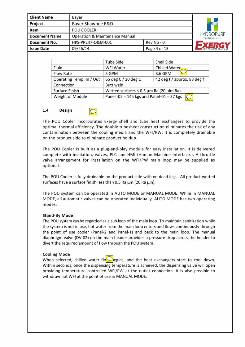
The POU Cooler incorporates Exergy shell and tube heat exchangers to provide the optimal thermal efficiency. The double tubesheet construction eliminates the risk of any contamination between the cooling media and the WFI/PW. It is completely drainable on the product side to eliminate product holdup. The POU Cooler is built as a plug-and-play module for easy installation. It is delivered complete with insulation, valves, PLC and HMI (Human Machine Interface.). A throttle valve arrangement for installation on the WFI/PW main loop may be supplied as optional. The POU Cooler is fully drainable on the product side with no dead legs. All product wetted surfaces have a surface finish less than 0.5 Ra µm (20 Ra µin). The POU system can be operated in AUTO MODE or MANUAL MODE. While in MANUAL MODE, all automatic valves can be operated individually. AUTO MODE has two operating modes: Stand-By Mode The POU system can be regarded as a sub-loop of the main loop. To maintain sanitization while the system is not in use, hot water from the main loop enters and flows continuously through the point of use cooler (Panel-2 and Panel-1) and back to the main loop. The manual diaphragm valve (DV-02) on the main header provides a pressure drop across the header to divert the required amount of flow through the POU system.. Cooling Mode When selected, chilled water flow begins, and the heat exchangers start to cool down. Within seconds, once the dispensing temperature is achieved, the dispensing valve will open providing temperature controlled WFI/PW at the outlet connection. It is also possible to withdraw hot WFI at the point of use in MANUAL MODE.
Tube Side Shell Side
Fluid WFI Water Chilled Water
Flow Rate 5 GPM 8.6 GPM
Operating Temp. In / Out 65 deg C / 30 deg C 42 deg f / approx. 88 deg f
Weight of Module Panel -02 = 145 kgs and Panel-01 = 37 kgs
dhodge
Sticky Note
Flow rate in submittal is 6.8 GPM
dhodge
Sticky Note
Make these units in LBS.
dhodge
Sticky Note
Needs to describe the exact design of these units. How the Master unit controls the slave unit. The slave has no heat exchanger.
dhodge
Sticky Note
Need to emphasize the time delay for the water to cool in the slave unit.
Client Name Bayer Project Bayer Shawnee R&D
Item POU COOLER
Document Name Operation & Maintenance Manual
Document No. HPS-PR247-O&M-001 Rev No - 0
Issue Date 09/26/14 Page 5 of 13
2.0 Installation and Initial Start-Up
2.1 Installation Recommendations
Do not install the heat exchanger under conditions that exceed the specified design conditions.
On the POU module Panel-02 connect the hot water inlet (N6), hot water outlet (N7), chilled water inlet (N1), chilled water outlet (N2), instrument air inlet (01), electrical supply 120V inlet (04), 24V DC outlet (05), HMI out (06), instrument air out (02) to AZDV-03, and instrument air out (03) to AV-01. Recommended pressure of instrument air is 80 psi (6 bar).
PANEL-02
dhodge
Sticky Note
Recommendations for grounding the units?
Client Name Bayer Project Bayer Shawnee R&D
Item POU COOLER
Document Name Operation & Maintenance Manual
Document No. HPS-PR247-O&M-001 Rev No - 0
Issue Date 09/26/14 Page 6 of 13
On the POU module Panel-01 connect the hot water inlet (N8) from Panel-02, hot water
outlet (N9)(return to header) and connect 24VDC in (03), HMI interface connection (04) as well as instrument air supply in (01) for valve AZDV-03 and instrument air supply in (02) for valve AV-01; all coming from Panel-02.
PANEL-01
- A counter-current flow through the heat exchangers gives the most efficient heat transfer, such that the incoming cooling water with low temperature, imparts maximum cooling effect to exiting WFI/PW. - If the POU System is installed at a low point, it can be used as a draining point of water system. - To ensure it is drainable, it is recommended to install the POU system in a vertical position. If installed in a horizontal position the POU module is no longer drainable.
Important: The double use point POU cooler module is to be installed through the wall. The single use point POU cooler module is to be installed on the wall. The installation should be strong enough to bear the load of the POU cooler modules. Read the drawings and check the distance from the wall, to make sure that there is proper alignment with the main loop pipe of the WFI/PW system.
Client Name Bayer Project Bayer Shawnee R&D
Item POU COOLER
Document Name Operation & Maintenance Manual
Document No. HPS-PR247-O&M-001 Rev No - 0
Issue Date 09/26/14 Page 7 of 13
2.2 The Pressure Drop Arrangement
In standby mode, hot water from the main loop enters through Panel-02 and flows
continuously through the POU cooler modules and returns from Panel-01 back to the main
loop, due to the pressure drop created across the diaphragm valve DV-02, which is to be
installed on the header across inlet and outlet connections of WFI /PW. The direction of flow should be as indicated by the arrows in the diagram below.
Pressure Drop Arrangement
2.3 Initial Start-Up Procedure
Upon initial start-up, with the system in MANUAL MODE, slowly start to circulate the chilled water only. Make sure that the entire cold side of the system is completely flooded. The WFI/PW should then be gradually introduced until the entire hot side of the system is completely flooded.
Client Name Bayer Project Bayer Shawnee R&D
Item POU COOLER
Document Name Operation & Maintenance Manual
Document No. HPS-PR247-O&M-001 Rev No - 0
Issue Date 09/26/14 Page 8 of 13
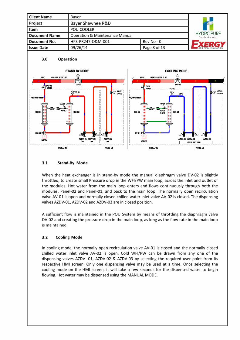
3.0 Operation
3.1 Stand-By Mode
When the heat exchanger is in stand-by mode the manual diaphragm valve DV-02 is slightly throttled, to create small Pressure drop in the WFI/PW main loop, across the inlet and outlet of the modules. Hot water from the main loop enters and flows continuously through both the modules, Panel-02 and Panel-01, and back to the main loop. The normally open recirculation valve AV-01 is open and normally closed chilled water inlet valve AV-02 is closed. The dispensing valves AZDV-01, AZDV-02 and AZDV-03 are in closed position.
A sufficient flow is maintained in the POU System by means of throttling the diaphragm valve DV-02 and creating the pressure drop in the main loop, as long as the flow rate in the main loop is maintained.
3.2 Cooling Mode
In cooling mode, the normally open recirculation valve AV-01 is closed and the normally closed chilled water inlet valve AV-02 is open. Cold WFI/PW can be drawn from any one of the dispensing valves AZDV -01, AZDV-02 & AZDV-03 by selecting the required user point from its respective HMI screen. Only one dispensing valve may be used at a time. Once selecting the cooling mode on the HMI screen, it will take a few seconds for the dispensed water to begin flowing. Hot water may be dispensed using the MANUAL MODE.
Client Name Bayer Project Bayer Shawnee R&D
Item POU COOLER
Document Name Operation & Maintenance Manual
Document No. HPS-PR247-O&M-001 Rev No - 0
Issue Date 09/26/14 Page 9 of 13
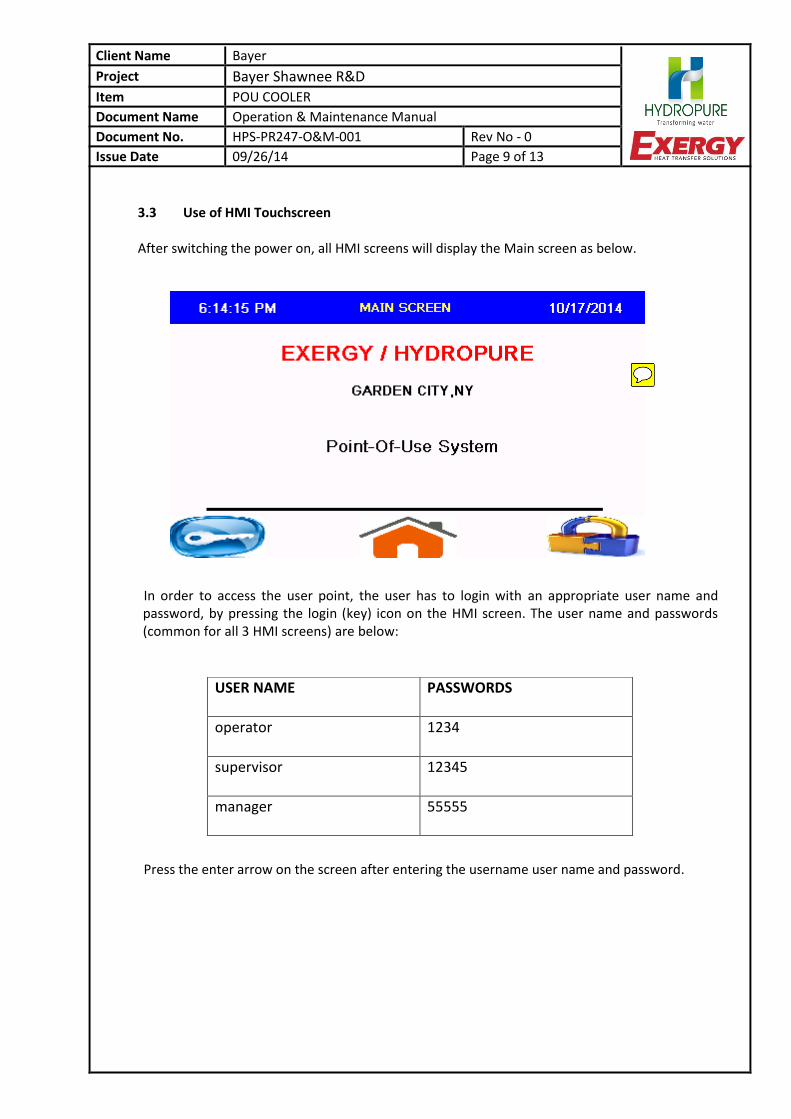
3.3 Use of HMI Touchscreen After switching the power on, all HMI screens will display the Main screen as below.
In order to access the user point, the user has to login with an appropriate user name and password, by pressing the login (key) icon on the HMI screen. The user name and passwords (common for all 3 HMI screens) are below:
Press the enter arrow on the screen after entering the username user name and password.
USER NAME PASSWORDS
operator 1234
supervisor 12345
manager 55555
dhodge
Sticky Note
Incorporate the screens below into the SAT for testing alarms, alerts and status points.
Client Name Bayer Project Bayer Shawnee R&D
Item POU COOLER
Document Name Operation & Maintenance Manual
Document No. HPS-PR247-O&M-001 Rev No - 0
Issue Date 09/26/14 Page 10 of 13
After successful login the user is required to press the home icon on the screen. The screen will then display as below.
Then the user can then select AUTO MODE or MANUAL MODE. The normal mode of operation is AUTO MODE. MANUAL MODE is used for maintenance or for individual manual operation of each valve. Pressing the MAIN button on screen will return the menu to home screen. Pressing the ALARM button on screen will open the ALARM screen showing ALARM history. The screen will display as below.
Client Name Bayer Project Bayer Shawnee R&D
Item POU COOLER
Document Name Operation & Maintenance Manual
Document No. HPS-PR247-O&M-001 Rev No - 0
Issue Date 09/26/14 Page 11 of 13
Pressing AUTO MODE will display the screen shown below.
The POU cooler will be in Stand-by Mode. The hot WFI/PW water will enter the Panel-02 and exit through Panel-01, back to the main header. All user points and the chilled water inlet valve will be closed. To dispense cooled WFI/PW, the user will press the red button icon on the screen, next to the dispense valve controlled by that HMI (ADZV01, 02 or 03). Pressing the button again closes the dispense valve and returns the system to Stand-by Mode. If the dispense valve button is pressed while another use point is being used, an alert message will appear on the screen and water will not be dispensed.
Client Name Bayer Project Bayer Shawnee R&D
Item POU COOLER
Document Name Operation & Maintenance Manual
Document No. HPS-PR247-O&M-001 Rev No - 0
Issue Date 09/26/14 Page 12 of 13
Pressing MANUAL MODE will display the screen shown below.
In this mode, the user can change the open/closed state of each automatic valve by pressing
the red button icon next to the valve on the system diagram. This mode can also be used to dispense hot WFI/PW. For setting the required parameters, the user has to press the “SET PARA” button on AUTO MODE screen. The screen will display as below. For description of parameters, please refer the interlock list.
Client Name Bayer Project Bayer Shawnee R&D
Item POU COOLER
Document Name Operation & Maintenance Manual
Document No. HPS-PR247-O&M-001 Rev No - 0
Issue Date 09/26/14 Page 13 of 13
3.4 Shut Down If the system is to be completely shut down for a long period of time: Drain all fluids from the product water side of heat exchanger. Water must be drained from tubes where there is a possibility of freezing. It is preferable to flush and fill the chilled water side with plain water or RO permeate water. 4.0 Maintenance
4.1 Cleaning of the Service (Cooling Medium) Side
Provide convenient means for frequently cleaning of the heat exchanger as suggested below:
1. Circulate chloride free cleaning solution through the service side at good velocity to remove sludge or other soft deposits.
2. Some soft deposits may be removed by circulating hot fresh water through the service side.
4.2 Steam-In-Place (SIP)
The POU system shall be in manual mode during a steam-in-place process, with the drain point, all user points (AZDV01,02 & 03), and the header return valve (AV-01) open. The chilled water valve (AV-02) shall be closed. Steam traps must be installed at the user points and drain point.
To avoid pressure build up above design conditions, it is very important that the service side (cooling medium side) is equipped with suitable safety valves or burst discs.
When the SIP operation is completed, remove condensate from the lowest drain points of the system. Make sure the product side is drained properly. Close the user points and drain point and allow the system to cool.
4.3 Gaskets
It is recommended that when a heat exchanger is disconnected, it should be reconnected using new
gaskets.
4.4 Spare Part List
Gaskets for 0.75” Tri Clamp
Diaphragm for Manual Block Valve
Diaphragm for Auto Diaphragm Valve
Diaphragm for Auto Zero Dead leg valves
Actuator for Auto Diaphragm Valves
Actuator for Zero Dead Leg Valves
Solenoid Coils for Auto Valves
dhodge
Sticky Note
Should price this up as a spare parts kit. We talked about doing this. Need to add quantities.


![[MS-WSPOL]: Web Services: Policy Assertions and WSDL ...... · [WSDL]. processing operation: A WSDL operation that is not a terminating operation. terminating operation: A WSDL operation](https://static.documents.pub/doc/80x56/5fee0a69f9c7494e656bdefe/ms-wspol-web-services-policy-assertions-and-wsdl-wsdl-processing.jpg)


