5.0 Model Number System .............................................................................................................. 506.0 Available Ranges, Multi-Conversions and Resolutions ............................................................ 517.0 Options, Replacement Kits ........................................................................................................ 54
ii UPS3000/UPS3110/UPS3210 Operation & Maintenance Manual
About This ManualThe bench-top UPS3000 and the rack-mountable UPS3110 and UPS3210 pneumatic pressure standards are rugged, compact instruments manufactured by CONDEC. They are designed to provide superior accuracy, range of calibration and ease of operation when used to assist in the manufacture, test and/or calibration of a wide variety of pressure sensing and measuring devices.These instruments utilize an extremely repeatable sensor coupled to microprocessor-based electronic circuitry and a selectable units display system. This provides easily readable and accurate digital representation of the measured pressure. If required for portable use, the optional battery models, are able to provide up to six hours of use.The UPS3110 all electro-mechanical device has our precision Orion vernier and one test port. Some models contain a front panel gage, to show the operator the input pressure, as well as, a pressure regulator that will act as a pressure limiter so that the operator can not over pressure a unit under test. A test hose is supplied for the customer. Standard front panel buttons and switches provide selection of the desired pressure range, push-button zeroing and the unique internal self-check feature.This manual has been written to give the user a simple and clear explanation of how to operate, calibrate and maintain these instruments.
Before attempting to use either style, Pressure Standard, the following instructions must be carefully read and understood by personnel utilizing the equipment. This is a high-pressure system. While a substantial effort has been expended to make this equipment safe, simple and fool-proof to operate, it is strongly recommended that only personnel formally trained in the use of pneumatic pressure equipment be permitted to operate it. Potentially dangerous conditions could be produced through negligent handling or operation of the console due to the high pressure contained within the unit.
UPS3110 units are strictly for use with pneumatic pressures. Erroneous readings and potential damage could result from the introduction of hydraulic fluids into the internal tubing lines.
Authorized distributors and their employees can view or download this manual from the Condec distributor site at www.4condec.com.
1
1.0 IntroductionUtilizing microprocessor technology, the UPS3000, rack-mountable UPS3110 and UPS3210 instruments offer a combination of features, performance, versatility and reliability not previously available in a single, self-contained pressure calibration instrument. The following list notes the features and benefits of each unit:
• Three independent switch-selectable pressure ranges per instrument.• Nine button-selectable units (PSI, kPa, Bar, mBar, kg/cm2, mmHg, inHg, cmH2O, inH2O) plus percent
of full scale may be displayed on instrument.• Accuracy of each range equal to or better than ±0.05% Full Scale.• Both “Gage” and “Absolute” pressure calibrations available via front panel switch selection.• Automatic self-check: Computer-controlled internal circuitry provides automatic maintenance of both
zero and span calibration data to insure long-term stability and accuracy.• Digital Display: Eliminates parallax, interpolation and operator judgement errors. Large, bright, red LED
digits provide excellent readability under all lighting conditions. • UPS3110 only - Using a manually adjustable regulator, the maximum system input pressure is adjusted
to any desired value higher (typically 20 to 50%) than the full scale range of the device being tested. By virtue of this technique, the unit under test is fully protected from being inadvertently over-pressurized.
• Fast Response: Pressure data refreshed and updated at the rate of 12 times per second.• Data Output: Serial Data, 20 mA loop, ASCII code format with start, stop and parity bits supplied as
standard practice. RS232 Simplex output available as an option.• Calibration Integrity: Tamper-proof design. Once calibrated, numerous safeguards guarantee the
integrity of pressure readings obtained. Display prompting provides the operator with functional status information during both operation and calibration.
• Pressure Media: UPS3000 and UPS3210, any gas or fluid compatible with 17-4 PH stainless steel alloy. UPS3110, only gas compatible with 17-4 PH stainless steel alloy.
• Simple Operation: All controls and indicators are accessible from the front panel. Accompanying operator's manual provides clear, concise instructions for system operation
• Safe, Clean Operation: All pressure components are made of brass, copper, aluminum or stainless steel and proof-tested to at least 150% of maximum operating pressure. In addition, the UPS3110 system contains a high-pressure relief valve to protect both the operator and system components from harm in the event of inadvertent over-pressurization.
The heart of this indicator/calibration system is a highly stable and repeatable pressure transducer. These sensors produce an electrical output signal which is linearly proportional to the applied pressure. This transduction technique has been employed by CONDEC for many years and has realized hundreds of thousands of hours of reliable operation.By combining these sensors with sophisticated microprocessor-based circuitry, an even higher degree of operational accuracy and precision has been accomplished. For example, computer-generated correction curves for both the non-linearity and the hysteresis of the sensors improve these characteristics by an order of magnitude or more. In addition, a “self-calibration” feature insures long-term accuracy by utilizing the computer to generate and control an internal “shunt calibration mode” of operation. The indicators full-scale reading is compared against, and if necessary, corrected to the digitally-stored value for full scale obtained at the time of initial pressure calibration.The UPS3000 and UPS3210 indicators, as well as, the UPS3110 calibrator has capability for an internal, rechargeable 12 volt lead acid battery, which provides a minimum of 6 hours of complete usage, when battery is fully charged. An ON/OFF switch is provided to conserve energy when the instrument is not in use. It also has a LO BATT indicator. After receiving and prior to operating new battery models, reinstall (+) cable, red wire, on battery.
With all its sophistication however, a great deal of effort has been expended to make the instruments simple to operate and easy to calibrate.Two micro-metering valves and vernier are provided to control the UPS3110 pressure source while the digital display indicates precisely the magnitude of the applied test pressure. Also, a pair of simple push-button switches provide both “zeroing” of the pressure display and the selection of either the “Gage” or “Absolute” calibration mode. In like manner, the “Range” selection is accomplished via a clearly marked rotary switch. Over-pressure protection is provided on lower pressure UPS3110 models via a fully adjustable pressure regulator which is manually set for each new device being tested.With respect to calibration, the instruments have been designed and programmed to be very user friendly in that they provide the operator with various prompting symbols and legends during each phase of the calibration sequence. Also, to prevent unauthorized tampering or calibrations, numerous features have been incorporated which greatly minimize this potential danger. Also, the electronic circuitry has been designed without any potentiometers or adjustments which eliminates the possibility of unwanted changes. Finally, the computer has been programmed with a series of internal self-diagnostic routines which continually monitor and check every bit of data stored and processed by this system, and immediately either notes or shuts down operation in the event of an out-of-tolerance reading or outright failures.The following schematic provides an overview of the UPS3110’s function.
Figure 1-1. UPS3110 Flow Diagram
Introduction 3
2.0 Operation
2.1 Unpacking and InspectionWhen received, carefully remove the instrument from its shipping container. A visual inspection of the instrument’s external surfaces should be performed immediately after unpacking. If obvious damage has been incurred during transit, the shipping agency and the distributor should be notified as soon as possible. Instructions as to how to proceed after assessment of the damage will then be determined. If the instrument shows no signs of damage, check to be sure all the required equipment and accessories have been received. See “Options, Replacement Kits” on page 54, for all options. NOTE: Prior to operating battery models, reinstall (+) cable, red wire, on battery.
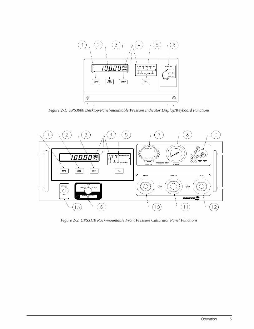
2.2 Standard Display/Keyboard Front Panel FunctionsUPS3000 See Figure 2-1 on page 5, UPS3110 See Figure 2-2 on page 5, UPS3210 See Figure 2-3 on page 6.
1. Six Digit LED display of the measured pressure. This display also prompts if a problem occurred in performing an operation.
2. Three Annuciators (4). Two of the LEDs are used for indicating whether the instrument is operating as a Gage pressure instrument or as an absolute (ABS) pressure instrument. The third LED indicates the conversion units that the pressure data is currently being displayed in.
3. ZERO function key (1). In GAGE mode and ABS only instruments this key allows the indicator to be zeroed.
NOTE: If attempting to perform a push to ZERO while the pressure data is in motion, the instrument will not go to ZERO.
NOTE: The four, or five if options have been installed, push button switches located across the lower face of the front panel are individually actuated by momentarily pressing with a light fingertip motion anywhere within the black outlines of the button. When actuated, each switch produces a visual feedback through the digital display.
4. ABS/GAGE function key (2), toggles instrument to be a Gage pressure instrument or an absolute (ABS) pressure instrument.
NOTE: This key is blank and non-functional if unit is an Absolute (Abs) only pressure unit or a Gage only pressure unit.
5. CONV conversion key (3), is used to select the conversion units that the pressure data is currently being displayed in.
6. CAL function key (5), activates the internal Self-Check feature. See “GAGE Mode Self-Check” on page 15.
NOTE: CAL key is non-functional in absolute mode.
7. RANGE SELECT switch (6), used to select the desired pressure range.NOTE: Do not turn switch between ranges during a cycle.
8. UPS3110 instrument with maximum range of 2K PSI or less: PRESSURE LIMIT CONTROL (7), for regulating the input pressure to the unit.
9. UPS3110 instrument with maximum range of 2K PSI or less: PRESSURE LIMIT MONITOR (8), indicates input pressure going to the unit.
10. UPS3110 instrument: TEST PORT (9), for connecting to the Device-Under-Test (DUT).11. UPS3110 instrument: INPUT Valve (10), used for nearing target pressure of the DUT.12. UPS3110 instrument: VERNIER Valve (11), used for precisely setting target pressure of the DUT.13. UPS3110 instrument: VENT Valve (12), used for venting pressure of the DUT.
Figure 2-2. UPS3110 Rack-mountable Front Pressure Calibrator Panel Functions
Operation 5
Figure 2-3. UPS3210 Rack-mountable Pressure Indicator Front Panel Functions
2.3 Rear Panel ConfigurationUPS3000 Series, See Figure 2-4 below, contains the following:
1. AC power cord, and input receptacle (17).2. INPUT PRESSURE port J1 (16), 7/16-20, 37o-4 AN male fitting.
Application of pressures greater than 1.5 times the highest pressure range of the indicator may cause calibration errors or even permanent damage to the pressure transducer.
3. The unit’s identification plate (15). 4. Optional if required items: • Connector J2 (14), 5 pin round MS style connector, for Serial or Analog Output communication board.• Connector J3 (20), 15 pin D connector, for the PCM1000 Controller Interface. • Connector (18), 5 pin round connector, for the Freeze Mode Cable.
NOTE: For further information, see “Options, Replacement Kits” on page 54.
UPS3110 Rack-mountable Series, See Figure 2-5 below, contains the following:1. AC power cord, fuse holder and input receptacle (17).2. INPUT PRESSURE port (16), 7/16-20, 37o-4 AN male fitting. Location of port for AC only units.
NOTE: The maximum input pressure, supplied by user, is noted below port.
3. The unit’s identification plate (15).4. VENT/VACUUM PORT (19), 7/16-20, 37o-4 AN male fitting.5. Optional if required items:
Connector J1 (14), 5 pin round MS style connector, for Serial or Analog Output communication board orlocation of Input Pressure port for models with battery.Connector J2 (18), 5 pin round connector, for the Freeze Mode Cable.
NOTE: For further information, see “Options, Replacement Kits” on page 54.
UPS3210 Rack-mountable Series, See Figure 2-6 on page 8, contains the following:1. AC power cord, fuse holder and input receptacle (17).2. INPUT PRESSURE port J3 (16), 7/16-20, 37o-4 AN male fitting.
NOTE: The maximum input pressure, supplied by user, is noted above port.
3. The unit’s identification plate (15).4. Optional if required items:
Connector J1 (14), 5 pin round MS style connector, for Serial or Analog Output communication board.Connector J2 (18), 5 pin round connector, for the Freeze Mode Cable. Connector J4, located below identification plate, required for APC4000/APC4001 interface cable.
NOTE: For further information, see “Options, Replacement Kits” on page 54.
2.4 Configuration Switch SettingsAs normally supplied, the UPS3000, UPS3110 and UPS3210 will be fully calibrated and configured to the requirements specified by the customer purchase order. However, there are several functions or operational features that may be selected or altered by the operator during usage. These are controlled by the eight-position DIP switch, S1, located on the CPU board as shown in Figure 2-7.NOTE: To gain access to the CPU board see “Case Removal and Installation” on page 28.
The APC4000 interface enable is activated only for models that are purchased and used with the PCM1000-1 controller or part of an APC4001 controller system. When UPS3000 or UPS3210 is used in conjunction with a controller, Peak Hold, Freeze Mode or MIN/MAX Mode options are not available. NOTE: UPS3110 is not used with a controller.
Approximately 1994 multi conversion software was added to UPS3000 models, therefore UPS3000 and PCM1000 units made prior to this will not work with the ones manufactured after that date. Consult factory for information on upgrading units.
2.4.2 Peak Hold or MAX/MIN Option EnableSee “Peak Hold Option” on page 54 or “Min and Max Mode Option” on page 55.
NOTE: * Absolute or Gage modes of operation are factory set, depending upon the style of transducer supplied and the type of internal memory configuration utilized.
When the Absolute/Gage switching is not utilized; the front panel ABS/GAGE push-button switch will be programmed to inactive and covered with a blank overlay. When the PEAK HOLD Option or MAX/MIN option is supplied switching from Absolute to Gauge mode via the front panel is possible and the Freeze Mode option, if supplied, is operable. NOTE: When the PEAK HOLD or MAX/MIN option is supplied, the CONV button is no longer active or present on front panel. Therefore, the required conversion must be set thru reconfiguration. See “Engineering Conversion with PEAK HOLD or MAX/MIN Option” on page 12 for applicable method to change to required conversion.
Switch Settings S1
Position 1 Position 2 Position 3 Position 4 Position 5 Position 6 Position 7 Position 8 UPS 3000UPS 3110UPS 3210
Table 2-2. Peak Hold or MAX/MIN Enable Switch Settings
Operation 9
2.4.3 Conversion Enable
As standard practice, the instruments are supplied with display indication in PSI (either Absolute, Gage or both) and capable of being converted to a range of nine units via the front panel CONV push-button switch.NOTE: When the PEAK HOLD or MAX/MIN option is supplied with a model having the ABS or GAGE mode, switch selectable from front panel, the “CONV” button will be disabled and will not be present on the front panel. Therefore, the required conversion must be set thru reconfiguration. See “Engineering Conversion with PEAK HOLD or MAX/MIN Option” on page 12 for applicable method to change to required conversion.
2.4.4 Digital Averaging
Digital Averaging is a technique whereby numerous update cycles are averaged together before the numerical display data is changed. In essence, this feature acts as a variable rate electronic filter to provide a more stable pressure indication reading.The “AUTO” mode of this filter allows the display to update rapidly (12/sec.) when the input pressure is being quickly changed and yet provides extremely stable display operation (3/sec.) when the desired pressure input value has been obtained.
2.4.5 AUTO-ZERO Maintenance (AZM) Enable
The Automatic Zero Maintenance (AZM) feature is used to “hold” the indicator reading to a “zero” value as long as the actual pressure input is maintained at zero. If the input pressure changes by more than one half a least significant display digit between two consecutive display update cycles, the “hold” feature is automatically disabled and the exact magnitude of pressure being exerted will be displayed. In some applications, it may be better to operate the instrument without the AZM circuit enabled. If so, pressing the ZERO push-button switch, with zero pressure applied to the instrument, will guarantee that each new pressure cycle begins at zero.
2.4.6 Automatic Span Maintenance (ASM) Enable
The Automatic Span Maintenance (ASM) circuit operates in conjunction with the front panel CAL push-button to provide a Self-Check feature that insures long-term accuracy by utilizing the computer to generate and control an internal “shunt calibration mode” of operation wherein the indicator reading obtained is compared against, and if necessary, corrected to the digitally-stored value for the same shunt calibration reading obtained at the time of initial pressure calibration.
Switch Setting S1 Position 3 Front Panel Conv Key Mode
0 Disabled
1 Enabled
Table 2-3. Conversion Enable Switch Setting
Switch Setting S1 Average Select Approximate Update Rate
2.5 Freeze Mode Option WiringSee Figure 2-7 on page 8 for TB location on CPU.Connections may be made using the Freeze Mode Kit, see “Freeze Mode Option - PN 57778” on page 54. The small five pin connector (pins A & B) which, in turn, are connected to the main CPU board via terminal block TB2-7 (+) (Pin A) and TB2-8 (Gnd Ret) (Pin B). The current through these wires is approximately 0.5 mA as a non-inductive load. The voltage between these two wires is 5 VDC. NOTE: Option may not be used with the APC4000/APC4001 Interface Option.
Figure 2-8. Freeze Mode Option Wiring
Operation 11
2.6 Engineering Conversion with PEAK HOLD or MAX/MIN OptionSee Figure 2-7 on page 8 for location of “Data Enter” and rocker switches.NOTE: When the PEAK HOLD or MAX/MIN option is supplied with a model having the ABS/GAGE mode, switch selectable from front panel, the CONV button will be disabled and will not be present on the front panel.
Figure 2-9. Peak Hold Option Front Panel Switches
Figure 2-10. MIN/MAX Option Front Panel Switches
In order to step the light bar on conversion display to required conversion the following steps must be taken:1. Open UPS3000/UPS3110/UPS3210 per Section 4.2.1 on page 28.2. At this time, record the settings of rocker switches S1 and S3. These settings must be changed in order to
program the new conversion configuration.3. Close the following rocker switches S1 position 3 and S3 positions 1 and 3.4. Verify Numeric display has “1 XXX”, where X’s are some random number.
NOTE: If 1 is not on display open rocker switch S1 position 3 and rocker switch S3 positions 1 and 3, then restart at step 3 above.
5. Push the ABS/GAGE switch located on front panel as needed to move light bar on conversion display to required conversion.
6. Momentarily push the “Data Enter” switch S2 to enter new conversion.7. Open the following rocker switches S1 position 3 and S3 positions 1 and 3.
NOTE: Verify rocker switches S1 and S3 conform to original settings which had been recorded earlier.
8. To verify proper conversion is active remove and restore power to the UPS3000/UPS3110/UPS3210.
2.7 UPS3000 or UPS3210 Initial Setup SequenceFor UPS3000, refer to Figure 2-1 on page 5 and Figure 2-4 on page 6. For UPS3210, refer to Figure 2-3 on page 6 and Figure 2-6 on page 8.
1. Connect the pressure source to the instrument via the INPUT PRESSURE port (16), 7/16-20, 37o-4 AN male fitting provided on the rear panel. It is suggested that a Cheat Seal, PN 54854, be used between INPUT PRESSURE port and pressure source fitting.
NOTE: Valves for venting and pressure input should be installed in line with the pressure source.
2. Apply power to the instrument using AC Cord (17) or, if applicable, by pressing POWER switch (13) on front panel and allow it to stabilize for at least 5 to 10 minutes.
3. Select the desired full scale pressure range via the three-position rotary RANGE SELECT switch (6). For the best accuracy, the selected range must be greater than, but close as possible to, the full scale range of the Device-Under-Test.
NOTE: Do not switch pressure ranges during a pressure cycle.
4. If applicable or required, select the mode of operation by momentarily depressing the ABS/GAGE push-button switch (2). The applicable “ABS” or “GAGE” light bar (4) will be lit to provide mode of operation.
5. To select the desired measurement display units, depress CONV push-button switch (3).NOTE: When the PEAK HOLD or MAX/MIN option is supplied with a model having the ABS or GAGE mode, switch selectable from front panel, the “CONV” button will be disabled and will not be present on the front panel. Refer to Section 2.6 on page 12.
6. If operating the unit in GAGE mode go to Section 2.7.1 or if operating the unit in ABS mode go to Section 2.7.2.
Application of pressures greater than 1.5 times the highest pressure range of the indicator may cause calibration errors or even permanent damage to the pressure transducer.
2.7.1 UPS3000 or UPS3210 Display of Pressure Sequence GAGE Mode1. Vent the Input Pressure port (16) to atmosphere.2. Momentarily depress the ZERO push-button switch (1). The display will indicate 0.00.3. The instrument is now fully configured and ready to display the applied pressure.
2.7.2 UPS3000 or UPS3210 Display of Pressure Sequence Absolute (ABS) ModeNOTE: If local barometric pressure is not 14.7, ABS/GAGE switch selectable units only, may need barometric offset. See “Barometric Offset - Absolute/Gage Switch Selectable Units ONLY” on page 23.
1. If only pressure measurements greater than barometric are required, continue to Step 1.1. If pressure measurements above and below atmospheric pressure are required go to step 2.
1.1. To apply pressure, close the customer supplied vent valve attached in line with the INPUT PRESSURE port (16). Unit will display applied pressure.
2. If pressure measurements above and below atmospheric pressure are required, connect a VACUUM PUMP in line with the INPUT PRESSURE port (16).
3. Close the customer supplied vent and input valve attached in line with the INPUT PRESSURE port (16). 4. Apply power to the vacuum pump and allow it to evacuate the system for several minutes or until the
digital display reading reaches equilibrium near Zero psia. Momentarily press the ZERO push-button switch (1) to establish a zero reference on the display.
5. The instrument is now fully configured and ready to display the applied pressure.
Operation 13
2.8 UPS3110 Initial Setup SequenceRefer to Figure 2-2 on page 5 and Figure 2-5 on page 7.
1. Connect the pressure source to the instrument via the INPUT PRESSURE port (16), 7/16-20, 37o-4 AN male fitting provided on the rear panel. It is suggested that a Cheat Seal, PN 54854, be used between INPUT PRESSURE port and pressure source fitting.
2. Check that the INPUT valve (10) is closed (rotate clockwise until it stops) and that the VENT valve (12) is open (two turns counter-clockwise from its stop).
3. Plug in the power cord (17) and energize the unit by pushing the POWER switch located on front panel. Allow at least 10 minutes warm-up time.
4. Select the desired full scale pressure range via the three-position rotary RANGE SELECT switch (6). For the best accuracy, the selected range must be greater than, but close as possible to, the full scale range of the Device-Under-Test (DUT).
NOTE: Do not switch pressure ranges during a calibration cycle.
5. Using the PRESSURE LIMIT CONTROL regulator (7), adjust the maximum system input pressure, as read by the PRESSURE LIMIT MONITOR (8), to any desired value higher (typically 20–50% higher) than the full-scale range of the DUT. Using this technique, the DUT is fully protected from being accidentally over-pressurized.
NOTE: UPS3110 []A[] and UPS3110 []G[] units do not have PRESSURE LIMIT CONTROL or MONITOR.
6. Connect the male end of the test hose to the TEST PORT (9) fitting.7. Connect the swivel fitting end (7/16-20) of the Test (output) hose to the DUT using adapters if required.
Tighten all connections properly.8. If applicable or required, select the mode of operation by momentarily depressing the ABS/GAGE (2)
switch. The applicable “ABS” or “GAGE” light bar (4) will be lit to provide mode of operation.9. To select the desired measurement display units, depress CONV (3) switch.
NOTE: When the PEAK HOLD or MAX/MIN option is supplied with a model having the ABS or GAGE mode, switch selectable from front panel, the “CONV” button will be disabled and will not be present on the front panel. Refer to Section 2.6 on page 12.
10. If operating the unit in GAGE mode go to Section 2.8.1 or if operating the unit in ABS mode go to Section 2.8.2.
2.8.1 UPS3110 Pressure Measurement Sequence GAGE Mode1. Press the ZERO push-button switch (1), display will return to a normal “Zero” reading. The instrument
may be zeroed at anytime, as long as the VENT valve (12) is open, by momentarily depressing the ZEROpush-button switch (1).
2. To apply pressure, close the VENT valve (12), approximately two turns, until it stops, then open the INPUTvalve (10) approximately 1/2 turn counter-clockwise until the numerical display begins to move. The pressure may change rapidly until reaching approximately 90% of the desired final value.
3. Use either the INPUT (10) or VENT valve (12) to obtain a specific pressure reading. Both provide precise control. As the pressure approaches the desired value, the valve being used for control should be rotated slowly clockwise to its closed position. With a little experience, pressure values very close to the desired final value may be quickly achieved.
4. To obtain exact pressure readings, slowly rotate the VERNIER control (11) knob in the direction required (clockwise to increase pressure) as indicated by the electronic numerical display.
Application of pressures greater than 1.5 times the highest pressure range of the indicator may cause calibration errors or even permanent damage to the pressure transducer.
2.8.2 UPS3110 Pressure Measurement Sequence Absolute (ABS) ModeNOTE: If local barometric pressure is not 14.7, ABS/GAGE switch selectable units only, may need barometric offset. See “Barometric Offset - Absolute/Gage Switch Selectable Units ONLY” on page 23.
1. If only pressure measurements greater than barometric are required, continue to step 1.1. If pressure measurements above and below atmospheric pressure are required go to step 2.To apply pressure, close the VENT valve (12), approximately two turns, until it stops, then open the INPUTvalve (10) approximately 1/2 turn counter-clockwise until the numerical display begins to move. The pressure may change rapidly until reaching approximately 90% of the desired final value.
1.1. Use either the INPUT (10) or VENT valve (12) to obtain a specific pressure reading. Both provide precise control. As the pressure approaches the desired value, the valve being used for control should be rotated slowly clockwise to its closed position. With a little experience, pressure values very close to the desired final value may be quickly achieved.
1.2. To obtain exact pressure readings, slowly rotate the VERNIER control (11) knob in the direction required (clockwise to increase pressure) as indicated by the electronic numerical display
Application of pressures greater than 1.5 times the highest pressure range of the indicator may cause calibration errors or even permanent damage to the pressure transducer.
2. If pressure measurements above and below atmospheric pressure are required, connect a VACUUM PUMP to the VACUUM/VENT port (19).
3. Open the VENT valve (12), close the INPUT valve (10) and apply power to the vacuum pump and allow it to evacuate the system for several minutes or until the digital display reading reaches equilibrium near Zero psia. Press the ZERO push-button switch (1) to establish a zero reference on the display.
4. With the vacuum pump still running, close the VENT valve (12) (approximately two turns to its stop) and check for system leaks. If there are none, continue to step 4.1.
4.1. To apply pressure, open the INPUT valve (10) (approximately 1/2 turn counter-clockwise until the numerical display begins to move). In general, the pressure may be changed rapidly until reaching approximately 90% of it desired final value.
4.2. Use either the INPUT (10) or VENT (12) valve to obtain a specific pressure reading. Both provide precise control. As the pressure approaches the desired value, the valve being used for control should be rotated slowly clockwise to its closed position. With a little experience, pressure values very close to the desired final value may be quickly achieved.
4.3. To obtain exact pressure readings, slowly rotate the VERNIER control (11) knob in the direction required (clockwise to increase pressure) as indicated by the electronic numerical display.
2.9 GAGE Mode Self-CheckFor UPS3000, refer to Figure 2-1 on page 5 and Figure 2-4 on page 6.For UPS3110, refer to Figure 2-2 on page 5 and Figure 2-5 on page 7.For UPS3210, refer to Figure 2-3 on page 6 and Figure 2-6 on page 8.NOTE: Use of this Self -Check is not required for the proper operation of unit. CAL key is non-functional in absolute mode due to the inability to simulate a perfect vacuum reference.
1. Vent the Input Pressure port (16) to atmosphere.2. Momentarily depress the ZERO push-button switch (1). The display will indicate 0.00.3. Momentarily depress the CAL push-button switch (5). The display will immediately blank except for two
“- -” which indicate that the unit is performing the self-check. If the self-check is successful, the display will flash “100.00” and revert to its normal zero indication.
Operation 15
2.10 Battery OperationFor replacement, see “Replacement Kits” on page 57.When supplied with the battery, the UPS3000/UPS3110/UPS3210 has an internal, rechargeable 12 volt, lead acid battery which provides a minimum of 6 hours of completely portable usage before having to be re-charged.The UPS3000/UPS3110/UPS3210 may be operated and/or recharged by simply connecting to a standard AC outlet via the line cord supplied. The battery re-charge cycle time is approximately 16 to 20 hours with the ON/OFF switch in the OFF position. The charging circuit is designed to be left on indefinitely without adversely affecting battery life.The battery voltage reading will typically be between 11.5 and 12.6 volts. When the battery voltage reads 11.5 volts there are approximately 1 to 2 hours of useful operation left and a LOW BATT indicator will be illuminated. A red LED in the lower left corner of unit near the POWER switch will turn on. The instrument will cease to function when the battery voltage is 11.0 volts or less.
2.11 Serial Output: 20 mA LoopNOTE: This may not be used with the following options in “DEMAND FORMAT”, APC4000 or APC4001 interface, Peak hold, Min/Max or Battery. This may not be used with the following options in “CONTINUOUS FORMAT”, APC 4000 or APC4001 interface or Battery.
Their are two modes of operation, Continuous or Demand.Continuous Mode: Model is continuously sending data.Demand Mode: Must be done from the front panel of the UPS3000/UPS3110/UPS3210 using a button. The button is the hidden one between the CONV and CAL button’s This is not a two-way mode and cannot be done externally by PC.
2.11.1 Hardware ConfigurationNOTE: See “Case Removal and Installation” on page 28.
UPS3000 Required Parts: PN 60607 Quantity 1, PN 58707 Quantity 1, PN 14839 Quantity 2, PN 58302, Quantity 1.UPS3110 and UPS3210 Required Parts: Contact factory for requirements.NOTE: Because of soldering it may be beneficial to have this installed at factory.
Solder Brown Wire to E13 and Red Wire to E14The serial output is accessed at J3, a 15-pin D-subminiature female connector at the rear of the unit. Pin designations are as follows: J3-8 +Tx (Brown wire) J3-9 -Tx (Red Wire)
2.11.2 Serial Output Software ConfigurationNOTES:
1. See “Case Removal and Installation” on page 28.
2. See Figure 2-7 on page 8 to locate DIP switches S1 and S3,as well as, switch S2 on CPU board.
3. See Figure 3-2 on page 20 for “STEPPER” and “ENTER” switch locations.
1. Open up the unit and power it up.2. On the main circuit board, close S3-1. The unit will display the following:
6 0 _ X X X where “X” can be any number3. Momentarily hit the STEPPER push-button switch until the number 64 is on the left side of the display.
The unit will display the following:
6 4 _ X X X where “X” can be any number
4. Refer to the “DATA FORMAT TABLE” in this section to determine the appropriate output format.
5. At this time, record the settings of switch S1. These settings must be changed in order to program the serial output configuration.
6. After the data format and baud rate have been selected, refer to the “SERIAL OUTPUT CONFIGURATION TABLE” in this section for the appropriate values for the M.S.D. “M” and the L.S.D. “L.”
7. Set up switch S1 with the data derived from the “Serial Output Configuration Table”. 8. After switch S1 has been set, push the ENTER button on front panel to enter the data.9. The selected values for “M” and “L” should now appear at location 64 in the correct order. If this is not
the case, go back and perform step “7” and try again.10. To store this information permanently, close switch S3-2. The unit will display the following:
_ 1 _ X X X where “X” can be any number11. Push switch S2 momentarily. As switch S2 is held down, the XXX on the display (see step “10”) becomes
377. Release switch S2.12. Return switch S1 to the original settings which had been recorded earlier in step “5”. Open switches on
switch S3 to resume normal operation.
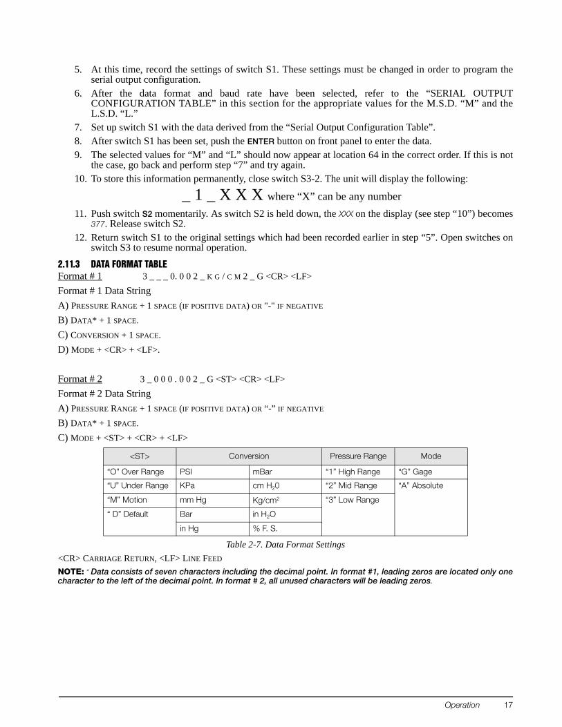
2.11.3 DATA FORMAT TABLEFormat # 1 3 _ _ _ 0. 0 0 2 _ K G / C M 2 _ G <CR> <LF>Format # 1 Data StringA) PRESSURE RANGE + 1 SPACE (IF POSITIVE DATA) OR "-" IF NEGATIVE B) DATA* + 1 SPACE.C) CONVERSION + 1 SPACE. D) MODE + <CR> + <LF>.
Format # 2 3 _ 0 0 0 . 0 0 2 _ G <ST> <CR> <LF>Format # 2 Data StringA) PRESSURE RANGE + 1 SPACE (IF POSITIVE DATA) OR “-” IF NEGATIVE B) DATA* + 1 SPACE.C) MODE + <ST> + <CR> + <LF>
<CR> CARRIAGE RETURN, <LF> LINE FEED
NOTE: * Data consists of seven characters including the decimal point. In format #1, leading zeros are located only one character to the left of the decimal point. In format # 2, all unused characters will be leading zeros.
<ST> Conversion Pressure Range Mode
“O” Over Range PSI mBar “1” High Range “G” Gage
“U” Under Range KPa cm H20 “2” Mid Range “A” Absolute
“M” Motion mm Hg Kg/cm2 “3” Low Range
“ D” Default Bar in H2O
in Hg % F. S.
Table 2-7. Data Format Settings
Operation 17
2.11.4 SERIAL OUTPUT CONFIGURATION TABLEEEPROM LOCATION 64 6 4 _ _ M L
0 = OPEN, 1 = CLOSEDMSD = MOST SIGNIFICANT DIGIT, LSD = LEAST SIGNIFICANT DIGITAll serial characters are ASCII and consist of the following:
3.0 Calibration and Adjustment ProcedureThe simple step-by-step calibration sequence provided on the following pages will permit a qualified technician to calibrate an entire UPS3000, UPS3110 or UPS3210 instrument in a matter of 45 minutes.However, it must be strongly emphasized that when performing these tests, the computer within the instrument is actually being re-programmed and as such, it is imperative that the pressure standard being used be in satisfactory operating condition and that the technician fully understands its operating characteristics and methods of usage. In addition, the UPS3000/UPS3110/UPS3210 itself must be properly warmed up (approximately 10 minutes) and electrically stabilized prior to performing a calibration cycle.NOTE: The CONDEC Repair Lab is equipped to do calibrations on CONDEC calibrators and pressure standards.Calibrations include a certification and are traceable to N.I.S.T (see“UPS3000/UPS3110/UPS3210 Return Material Authorization Form”).
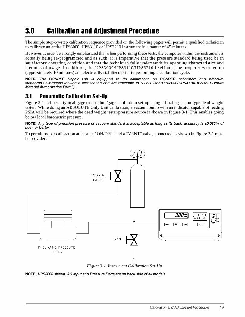
3.1 Pneumatic Calibration Set-UpFigure 3-1 defines a typical gage or absolute/gage calibration set-up using a floating piston type dead weight tester. While doing an ABSOLUTE Only Unit calibration, a vacuum pump with an indicator capable of reading PSIA will be required where the dead weight tester/pressure source is shown in Figure 3-1. This enables going below local barometric pressure. NOTE: Any type of precision pressure or vacuum standard is acceptable as long as its basic accuracy is ±0.025% of point or better.
To permit proper calibration at least an “ON/OFF” and a “VENT” valve, connected as shown in Figure 3-1 must be provided.
Figure 3-1. Instrument Calibration Set-Up
NOTE: UPS3000 shown, AC Input and Pressure Ports are on back side of all models.
Calibration and Adjustment Procedure 19
3.2 Instrument Calibration Set-UpNOTE: See“Case Removal and Installation” on page 28 and Figure 2-7 on page 8 to locate DIP switch S3 on CPU board.
UPS3000 is placed into its calibrate mode by momentarily opening instrument drawer and setting the DIP switch, S3 in accordance with Table 3-1. Connect Test Standard to UPS3000 Input Port.UPS3110, disconnect the input pressure and power lines and remove the unit from its rack. Remove the top cover. Set the DIP switch, S3 in accordance with Table 3-1 and connect Test Standard to UPS3110 Test Port.UPS3210, disconnect the input pressure and power lines and remove the unit from its rack. Remove the top cover. Set the DIP switch, S3 in accordance with Table 3-1 and connect Test Standard to UPS3210 Input Port.
In the CALIBRATE mode the UPS3000/UPS3110/UPS3210’s digital displays are used to provide the operator with prompting symbols, as well as displaying the various data formats employed. The front panel button switch, under the middle of the display, becomes a sequential STEPPER key used to select the various programming functions (Zero/Span, Linearity/Hysteresis, Shunt Resister Calibration) and the push-button (CAL) directly beneath the conversion display is used as the ENTER switch.All calibration functions will be performed in PSI engineering units, as “Gauge” (atmospheric reference) measurements, unless the instrument being calibrated has been configured as an “Absolute Only” unit. If so, the procedures in this section should be followed, except that an absolute (0 psia) reference must be utilized. A good 2-stage vacuum pump should be employed to attain greater than 100 microns Hg. vacuum.Figure 3-2 depicts the location of the above described front panel switches as well as showing the display format obtained as soon as the unit has been placed in the CALIBRATE mode.
Figure 3-2. Calibration Keys
NOTE: UPS3000 shown Input Port located on back of unit.
Switch Settings S3
Program Switch ModePosition 1 Position 2 Position 3 Position 4
0 0 0 0 Operate
1 0 1 0 Calibrate
Table 3-1. CALIBRATE/OPERATE Switch Settings
20 UPS3000/UPS3110/UPS3210 Operation and Maintenance Manual
3.3 Zero/Span Calibration Pressing the STEPPER push-button switch once places the instrument into its ZERO/SPAN calibration mode. The display will be shown in Figure 3-3.
Figure 3-3. Zero/Span Calibration for Gage Only Units (Each Range)
Starting with the instrument’s lowest pressure range, sequentially perform steps 1 and 2 shown in Table 3-2 for each pressure range. Perform the following for each step.NOTE: Perform Step 1 in all ranges prior to doing Step 2.
1. Adjust input pressure to the appropriate (either 0 or 100%) value.2. Perform the action indicated by the table when pressure input readings are stable.
NOTES:
1. If readings are not stable or are not within ± 20% of zero, the zero correction cannot be entered.
2. If readings are not stable or are not within ± 5% of 100%, the span correction cannot be entered.
3.4 Linearity and Hysteresis CalibrationThe unit can be placed in LINEARIZATION/HYSTERESIS mode by pressing the STEPPER push-button under the middle of the display as shown in Figure 3-2. The display is shown in Figure 3-4.NOTE: The zero/span calibration needs to be performed prior to linearity and hysteresis calibration. For Absolute Only Unit, vacuum pump with PSIA indicator must be used to obtain readings below local barometric pressure.
Figure 3-4. Linearity and Hysteresis Calibration
Starting with the instrument's lowest pressure range, sequentially perform the thirteen steps described in Table 3-3 on page 22, for each pressure range being calibrated. Perform the following for each step.
1. Adjust input pressure to the appropriate value without overshooting the setting.
2. Perform the action as indicated when the readings are stable.
When step number 11 is reached, the display will change so that the left most status symbol will be “H”. This will remain for step 12 and down to approximately 0.00 psi.NOTES:
1. If reading is in motion or correction required is not within ±0.8% of Full-Scale, no entry will be made.
2. If entry is valid, the display will momentarily indicate the correction value (in percent) and the memory location at which it is stored.
3. If 100% ±0.05% is not obtained, repeat the Zero/Span calibration sequence.
STEP NO.INPUT PRESSURE,
% OF RANGEOPERATOR ACTION
REQUIREDSTATUS SYMBOL IN LEFT MOST DIGIT
REMARKS
1 0 Press ZERO Switch “Upper Circle” Zero on Display
22 UPS3000/UPS3110/UPS3210 Operation and Maintenance Manual
3.5 Shunt Resistor CalibrationPress the STEPPER push-button again to select the SHUNT RESISTOR CALIBRATION mode. The display will be as shown in Figure 3-5.
Figure 3-5. Shunt Resistor Calibration
With the UPS3000/UPS3110/UPS3210’s highest pressure range selected, perform the four step sequence described below:
1. Be sure the input pressure to the UPS3000/UPS3110/UPS3210 is at zero psig.NOTE: For Absolute Only Unit, vacuum pump with PSIA indicator must be used to obtain zero reading.
2. Press and hold the ZERO push-button switch on the front panel until a stable zero indication is obtained. 3. Release the ZERO push-button switch and allow the display to stabilize at its shunt resistor calibration
number, (100 ± 5.00%).4. Press the ENTER push-button switch, as shown in Figure 3-2 on page 20, on the front panel. If accepted,
the bottom half of all display digits will momentarily illuminate.
3.6 Permanent Data Storage After completing the above calibration procedures, the new data that has been entered into the computer must be permanently stored. The sequence to do this is as follows:
1. Pressing the STEPPER push-button again, as shown in Figure 3-2 on page 20, will bring the indicator back to its initial Data Recall display condition as shown in Figure 3-2.
2. Open the instrument and depress the DATA ENTER switch, S2, located approximately in the middle of the circuit board.
NOTE: See “Case Removal and Installation” on page 28 and for "DATA ENTER" switch location see Figure 2-7 on page 8.
3. If the data is accepted, the three-digit number on the right side of the display will indicate 1 377 for as long as the DATA ENTER switch, S2, is depressed.
4. The calibration is now complete and CALIBRATE/OPERATE switch, S3, must be returned to its normal operating positions as shown in Table 3-1 on page 20. The pressure standard may now be disconnected.
3.7 Barometric Offset - Absolute/Gage Switch Selectable Units ONLYNOTES: This section is only required if barometric conditions are higher or lower than 14.7 PSIA.
See“Case Removal and Installation” on page 28. See Figure 2-7 on page 8 for S3, CALIBRATE/OPERATE configuration switch and S2 "DATA ENTER" switch location. See Figure 3-2 on page 20 for STEPPER and ENTERpush-button switch locations.
If required, obtain the current barometric pressure from a pressure standard with an accuracy of.025% or better, to calibrate the absolute zero at the current barometric pressure. Remove top cover and CALIBRATE/OPERATE switch, S3, must be changed to its calibrate positions as shown in Table 3-1 on page 20. Using the STEPPER push-button place the unit into ZERO/SPAN calibration mode as shown in Figure 3-3 on page 21.
Calibration and Adjustment Procedure 23
3.7.1 For UPS3000/UPS3210 Absolute/Gage Switch Selectable Units ONLYIf the current barometric pressure is below 14.7 PSIA, the offset is positive, see Example 1. If the current barometric pressure is above 14.7 PSIA, the offset is negative, see Example 2. If the current barometric pressure is 14.7 PSIA, then no offset is needed.
Example 1:If the current barometric pressure is lower than 14.70 PSIA, subtract the current barometric pressure from 14.70. 14.70 PSI: UPS3110 reference point -14.55 PSI: Current barometric pressure 0.15 PSI: Positive Delta OffsetComplete the following stepsNOTE: UPS3000 refer to Figure 2-1 on page 5 and Figure 2-4 on page 6. UPS3210 refer to Figure 2-3 on page 6 and Figure 2-6 on page 8.
1. Connect Test Standard to UPS3000/UPS3210 Input Port similar to Figure 3-1 on page 19.2. Open the vent valve connected between Test Standard and UPS3000/UPS3210.3. Using the RANGE SELECT switch (6), select the lowest pressure range on the UPS3000/UPS3210.4. Press the ENTER push-button, as shown in Figure 3-2 on page 20, on the UPS3000/UPS3210. The
display reads zero. Repeat this step for the middle and high ranges.5. Close the vent valve connected between Test Standard and UPS3000/UPS3210. Select the lowest
pressure range of the UPS3000/UPS3210.6. Input a pressure into the UPS3000/UPS3210 until the display reads the value of the Positive Delta
Pressure, 0.15 PSI as in this example.7. Depress the ENTER push-button on the UPS3000/UPS3210. The display reads zero. Without touching the
input pressure repeat this step for the middle and high ranges.8. Using the STEPPER push-button, as shown in Figure 3-2 on page 20, place the unit into SHUNT RESISTOR
CALIBRATION mode. The display will be as shown in Figure 3-5 on page 23.9. With UPS3000/UPS3210 RANGE SELECT switch (6) switched in the high range, depress the ZERO
push-button on the front panel. Verify that the display reads 0.00. Upon release of the push-button the display will be as shown in Figure 3-5 on page 23.
10. Depress the ENTER push-button. The display will respond with “[] [] [] [] [] []” until the button is released.
11. Pressing the STEPPER push-button bring the indicator back to its initial Data Recall display condition as shown in Figure 3-2 on page 20. The display shows 1 XXX (three arbitrary digits).
12. Depress the DATA ENTER switch, S2, located approximately in the middle of the circuit board. See Figure 2-7 for the switch location.
13. If the data is accepted, the three-digit number on the right side of the display will indicate 377 for as long as the DATA ENTER switch, S2, is depressed.
14. The barometric offset is now complete and CALIBRATE/OPERATE switch, S3, must be returned to its normal operating positions as shown in Table 3-1 on page 20. The Test Standard may now be disconnected.
24 UPS3000/UPS3110/UPS3210 Operation and Maintenance Manual
Example 2:If the current barometric pressure is above 14.70 PSIA, subtract the current barometric pressure from 14.70. 14.70 PSI: UPS3110 reference point -14.75 PSI: Current barometric pressure -.05 PSI: Negative Delta Offset
Figure 3-6. Vacuum Pump Setup
Complete the following steps:NOTE: UPS3000 refer to Figure 2-1 on page 5 and Figure 2-4 on page 6. UPS3210 refer to Figure 2-3 on page 6 and Figure 2-6 on page 8.
1. Connect Vacuum Test Standard to UPS3000/UPS3210 Input Port similar to Figure 3-6. A vacuum pump will need to be connected such that the Vacuum Test Standard controls the output coming from the vacuum pump going into the INPUT PRESSURE port (16) of the UPS3000/UPS3210.
2. Open the vent valve connected between Test Standard and UPS3000/UPS3210.3. Using the RANGE SELECT switch (6), select the lowest pressure range on the UPS3000/UPS3210.4. Press the ENTER push-button, as shown in Figure 3-2 on page 20, on the UPS3000/UPS3210. The
display reads zero. Repeat this step for the middle and high ranges.5. Close the vent valve connected between Vacuum Test Standard and UPS3000/UPS3210. Select the
lowest pressure range of the UPS3000/UPS3210.6. Turn the vacuum pump on creating a vacuum. Using the Vacuum Test Standard to control the vacuum
until the UPS3000/UPS3210 display reads the value of the Negative Delta Pressure, -0.05 PSI as in this example.
7. Depress the ENTER push-button on the UPS3110. The display reads zero. Without touching the Vacuum Test Standard settings repeat this step for the middle and high ranges.
8. Using the STEPPER push-button, as shown in Figure 3-2 on page 20, place the unit into SHUNT RESISTOR CALIBRATION mode. The display will be as shown in Figure 3-5 on page 23.
9. With UPS3000/UPS3210 RANGE SELECT switch (6) switched in the high range, depress the ZEROpush-button on the front panel. Verify that the display reads 0.00. Upon release of the push-button the display will be as shown in Figure 3-5 on page 23.
10. Depress the ENTER push-button. The display will respond with “[] [] [] [] [] []” until the button is released.
11. Pressing the STEPPER push-button bring the indicator back to its initial Data Recall display condition as shown in Figure 3-2 on page 20. The display shows 1 XXX (three arbitrary digits).
12. Depress the DATA ENTER switch, S2, located approximately in the middle of the circuit board. See Figure 2-7 for the switch location
13. If the data is accepted, the three-digit number on the right side of the display will indicate 377 for as long as the DATA ENTER switch, S2, is depressed.
14. The barometric offset is now complete and CALIBRATE/OPERATE switch, S3, must be returned to its normal operating positions as shown in Table 3-1 on page 20. The Vacuum Test Standard may now be disconnected.
Calibration and Adjustment Procedure 25
3.7.2 For UPS3110 Absolute/Gage Switch Selectable Units ONLYIf the current barometric pressure is below 14.7 PSIA, the offset is positive, see Example 1. If the current barometric pressure is above 14.7 PSIA, the offset is negative, see Example 2. If the current barometric pressure is 14.7 PSIA, then no offset is needed.
Example 1:If the current barometric pressure is lower than 14.70 PSIA, subtract the current barometric pressure from 14.70. 14.70 PSI: UPS3110 reference point -14.55 PSI: Current barometric pressure 0.15 PSI: Positive Delta OffsetComplete the following steps (refer to Figure 2-2 on page 5 and Figure 2-5 on page 7):
1. Open the VENT valve (12) and close the INPUT (10) valve.2. Using the RANGE SELECT switch (6), select the lowest pressure range on the UPS3110.3. Press the ENTER push-button, as shown in Figure 3-2 on page 20, on the UPS3110. The display reads
zero. Repeat this step for the middle and high ranges.4. Close the VENT valve (12). Select the lowest pressure range of the UPS3110.5. Turn the VERNIER (11) of the UPS3110 clockwise, creating a pressure until the display reads the value of
the Positive Delta Pressure, 0.15 PSI as in this example.6. Depress the ENTER push-button on the UPS3110. The display reads zero. Without touching the VERNIER
(11) knob repeat this step for the middle and high ranges.7. Using the STEPPER push-button, as shown in Figure 3-2 on page 20, place the unit into SHUNT RESISTOR
CALIBRATION mode. The display will be as shown in Figure 3-5 on page 23.8. With UPS3110 RANGE SELECT switch (6) switched in the high range, depress the ZERO push-button on
the front panel. Verify that the display reads 0.00. Upon release of the push-button the display will be as shown in Figure 3-5 on page 23.
9. Depress the ENTER push-button. The display will respond with “[] [] [] [] [] []” until the button is released.
10. Pressing the STEPPER push-button bring the indicator back to its initial Data Recall display condition as shown in Figure 3-2 on page 20. The display shows 1 XXX (three arbitrary digits).
11. Depress the DATA ENTER switch, S2, located approximately in the middle of the circuit board. See Figure 2-7 for the switch location
12. If the data is accepted, the three-digit number on the right side of the display will indicate 377 for as long as the DATA ENTER switch, S2, is depressed.
13. The barometric offset is now complete and CALIBRATE/OPERATE switch, S3, must be returned to its normal operating positions as shown in Table 3-1 on page 20.
Example 2:If the current barometric pressure is above 14.70 PSIA, subtract the current barometric pressure from 14.70. 14.70 PSI: UPS3110 reference point -14.75 PSI: Current barometric pressure -.05 PSI: Negative Delta OffsetNOTE: Normally the negative offset is small enough to prevent the need of a vacuum pump.
Complete the following steps (refer to Figure 2-2 on page 5 and Figure 2-5 on page 7):1. Open the VENT valve (12) and close the INPUT (10) valve.2. Using the RANGE SELECT switch (6), select the lowest pressure range on the UPS3110.3. Press the ENTER push-button, as shown in Figure 3-2 on page 20, on the UPS3110. The display reads
zero. Repeat this step for the middle and high ranges.4. Close the VENT valve (12). Select the lowest pressure range of the UPS3110.5. Turn the VERNIER (11) of the UPS3110 counter-clockwise, creating a vacuum until the display reads the
26 UPS3000/UPS3110/UPS3210 Operation and Maintenance Manual
value of the Negative Delta Pressure, -0.05 PSI as in this example.6. Depress the ENTER push-button on the UPS3110. The display reads zero. Without touching the VERNIER
(11) knob repeat this step for the middle and high ranges.7. Using the STEPPER push-button, as shown in Figure 3-2 on page 20, place the unit into SHUNT RESISTOR
CALIBRATION mode. The display will be as shown in Figure 3-5 on page 23.8. With UPS3110 RANGE SELECT switch (6) switched in the high range, depress the ZERO push-button on
the front panel. Verify that the display reads 0.00. Upon release of the push-button the display will be as shown in Figure 3-5 on page 23.
9. Depress the ENTER push-button. The display will respond with “[] [] [] [] [] []” until the button is released.
10. Pressing the STEPPER push-button bring the indicator back to its initial Data Recall display condition as shown in Figure 3-2 on page 20. The display shows 1 XXX (three arbitrary digits).
11. Depress the DATA ENTER switch, S2, located approximately in the middle of the circuit board. See Figure 2-7 for the switch location
12. If the data is accepted, the three-digit number on the right side of the display will indicate 377 for as long as the DATA ENTER switch, S2, is depressed.
13. The barometric offset is now complete and CALIBRATE/OPERATE switch, S3, must be returned to its normal operating positions as shown in Table 3-1 on page 20.
Calibration and Adjustment Procedure 27
4.0 Maintenance & Service
4.1 Troubleshooting
4.2 Maintenance & Service ProceduresThis section outlines the mechanical and BASIC electrical repair procedures for the portable pneumatic pressure calibrator, model UPS3000/UPS3110/UPS3210. The repair procedures cover the major components and sub-assemblies which are critical to the proper functioning of the calibrators and that will likely need periodic maintenance over the life of the unit. Only those persons who are formally trained as skilled technicians should attempt to repair these units. All relevant safety precautions should be observed due to the presence of electrical components and high-pressure.
4.2.1 Case Removal and Installation
UPS3000 External Case Removal/InstallationNOTE: Verify pressure has been vented from system prior to case removal. Although not recommended the instrument may be fully operated with the case removed without any potentially lethal shock hazard to operating personnel, since accessible internal voltage is nominally 25 VDC.
1. Loosen the two thumbscrews (PN 68916) located at the bottom outermost corners of the front panel. Screws will remain captivated to front panel but will allow chassis to slide away from rear of case.
2. Use screws to slide front panel/chassis away from case. 3. If all power and pressure connections have been removed. Gently slide panel/chassis out until back edge
of panel/chassis touches lip on front of case.4. Tilt front of panel/chassis upward slightly and remove from case. Place assembly on a bench top.
Reverse procedure for installation.
Symptom Problem Remedy
Display not lit Unit will not energize Check fuse, check power source, if applicable check power switch
Display slowly decreases over time Leak in system Check all compression and pipe fittings with snoop, bottle of liquid leak gas detector (PN 64781)
Display does not respond when Vernier knob is turned
No Vernier control Readjust isolation valves on Orion; replace O-ring on Vernier piston
Display increases or decreases when INPUT (Pressure) or VENT valves are closed
No pressure or vent control Replace valve seats or O-rings in valves; check valve needles
Unit will not stay in CAL, display shows "O", display reads a high value @ zero PSIG
Transducer over-pressurized Replace transducer
Low battery indicator on display illuminates when unit is powered
Low or no battery power Re-charge battery, check power supply charging voltage
No display when in battery mode after charging
Battery will not hold charge Replace battery
Display will not zero Perform a ZERO/SPAN calibration
Display will shift, will not be steady Transducer drifts or possible over pressure
28 UPS3000/UPS3110/UPS3210 Operation and Maintenance Manual
UPS3110/UPS3210 Removal/Installation
RemovalTools required: Phillips screwdriver
1. Vent system and remove input pressure source. Disconnect power cord, hoses, connectors, etc. from rear of UPS3110/UPS3210. Remove from rack, if applicable, by grasping the handles located on the front of the unit and gently set the rack-mount assembly on a bench top. It can be rested on the panel bottom and chassis edge.
2. Loosen and remove the three screws (PN 14839) from rear and sides that secure the cover to the chassis.
InstallationTools required: Phillips screwdriver
1. Align mounting holes of cover with chassis and install three screws (PN 14839) from rear and sides that secure the cover to the chassis.
2. Lift the panel and chassis by grasping the handles located on the front of the unit and re-install in rack, if applicable. Connect input pressure source, power cord, hoses, connectors, etc. to rear of UPS3110/UPS3210.
4.2.2 ORION 2C (PN 55283) or ORION 3A (PN 55287) Manifold Removal Refer to Figure 2-2 on page 5.Tools required: Phillips screwdriver
11/32" Wrench or nutdriver.061" Hex wrenchAdjusting screwdriver (small flat-blade)11/32" Open end wrench (thin)7/16" Open end wrench
1. Vent any remaining gas from the system to atmosphere. 2. Remove cover from chassis as described in Section 4.2.1 on page 28. 3. Remove the Test Port to Orion tubing section using a 7/16" wrench. 4. If the transducer is wired via a connector, remove the connector by turning counter-clockwise. If the
transducer is “hard-wired,” loosen and remove the 4 transducer wires (red, white, green, black) from the terminal block, TB1, on the CPU board, using the small flat-blade screwdriver.
NOTE: Mark TB positions on end of wires to help when reinstalling transducer.
5. Break the wire ties, if applicable, that hold the transducer wires so that the wires are “free.” 6. Using the 11/32" thin wrench, loosen and carefully remove the transducer from the Orion manifold.7. Remove the tubing sections from the Vent and Pressure inlet fittings on the Orion manifold, using a
7/16" wrench.8. Remove the panel knobs from the INPUT (10) (pressure), VERNIER (11) and VENT (12) valves using the
.061” hex wrench.9. Loosen and remove the 2 panel screws (PN 60837) from the panel front that secure the manifold to the
panel.10. Remove the manifold from the front panel.
Maintenance & Service 29
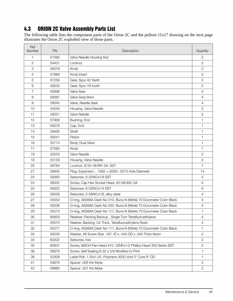
4.2.3 ORION Manifold - Valve Seat RemovalORION 2C: Refer to “ORION 2C Valve Assembly Parts List” on page 45 and Figure 4-1 on the following foldout 11 x 17 sheet.ORION 3A: Refer to “ORION 3A Valve Assembly Parts List” on page 47 and Figure 4-2 on the second foldout 11 x 17 sheet.Tools required: A/R solvent (de-natured alcohol)
Torque wrenchSocket wrench Needle-nose pliers3/4" Socket Tube fluorinated Krytox® grease (PN 55593)Needle housing socket (65580) Electric hand drill
Isolation valve needle housing socket (PN 68509) Tap handleHex wrench (.050") No. 43 drill bitHex wrench (.061") No. 4-40 tap
Small hammer Socket wrench
1. Secure the manifold by its center portion, in a bench vise, with the valve knobs pointing upward.2. Using the .061" hex wrench, loosen and remove the knob inserts (4) from the pressure and vent valve
stems.3. Using the .050" hex wrench, loosen and remove the setscrew (34) and lock nut (2).4. Loosen the 3/4" locknuts (1) on the pressure and vent valve threaded needle housings (10).5. Using the needle housing socket (65580) and torque wrench, loosen and remove the needle/housing
assembly (10, 1).6. To disassemble the isolation valve, first remove the valve needle (18) by turning the gear clockwise.7. Loosen and remove the valve housings (19) using the isolation valve needle housing removal socket
(68509) and socket wrench.8. Remove the valve stem seats (8) and valve needle seats (9) using the needle-nose pliers.9. Remove the inner and outer O-rings (28, 27) and back-up rings (31, 30) from the valve stem seats and
wash all parts in solvent (de-natured alcohol).10. To remove valve seats (7) from either the input (pressure), vent or isolation valves, try blowing
compressed air through the inlet and outlet fittings. Otherwise, the center holes will have to be drilled and a tap used to extract the seat (Steps 11-14).
11. Using the electric hand drill with the No. 43 bit, carefully drill out the seat hole, ensuring that the drill does not touch the hole in the manifold housing directly beneath the seat.
12. Blow out any chips from the seat area using compressed air.13. While holding the 4-40 tap steady and perpendicular to the seat, slowly turn until the tap starts to engage
the seat.14. When the tap has engaged into the seat, use a small hammer and gently knock upward against the tap
handle to extract the seat.15. After the seat has been removed, blow any remaining chips from the seat area.
30 UPS3000/UPS3110/UPS3210 Operation and Maintenance Manual
4.2.4 ORION Manifold - Vernier Control DisassemblyORION 2C: Refer to “ORION 2C Valve Assembly Parts List” on page 45 and Figure 4-1 on the following foldout 11 x 17 sheet.ORION 3A: Refer to “ORION 3A Valve Assembly Parts List” on page 47 and Figure 4-2 on the second foldout 11 x 17 sheet.Tools required: A/R solvent (de-natured alcohol)
1-1/4" open end wrenchScrewdriver (flat-blade)Socket wrenchIsolation valve needle housing socket (PN 68508)
Isolation valve needle housing socket (PN 68509)
1. With the manifold housing mounted in a vise, turn the vernier shaft (14) clockwise until the piston is bottomed.
2. Loosen and remove the end cap (13) using a 1-1/4" wrench. At certain points during removal the end cap will appear to lock up. If this occurs, rotate the shaft clockwise until the end cap is free to turn.
3. Remove the O-ring (29) from the end cap.ORION 3A: Also remove the backup washer (38) from the end cap.
4. Remove the self-sealing screw (36) that acts as the piston key.5. Extract the piston (15) by partially screwing in the threaded end of the shaft and pulling.6. Remove the O-ring (32) from the piston groove.7. To disassemble the end cap/shaft assembly, mount the end cap in the vise. 8. Loosen and remove the locknut (20) using the isolation valve housing socket (PN 68509) and socket
wrench.9. ORION 2C: Loosen and remove the end bushing (12) using the same socket (PN 68509). Remove the
shaft (14). Remove the mylar bearing washers (41 or 42) from both sides of the shaft flange. ORION 3A: Loosen and remove the end bushing (12) using the isolation valve housing socket (PN 68508) and socket wrench. Remove the shaft (14). Remove the ball bearings (41) from both sides of the shaft flange.
10. Use a small pick or screwdriver to remove the O-ring (27) from the inner groove of the end cap (13).ORION-3A: Also remove backup retainer (39) from inner groove of the end cap (13).
11. Wash all parts in solvent and blow dry with compressed air.
4.2.5 ORION Manifold - Vernier Control ReassemblyORION 2C: Refer to “ORION 2C Valve Assembly Parts List” on page 45 and Figure 4-1 on the following foldout 11 x 17 sheet.ORION 3A: Refer to “ORION 3A Valve Assembly Parts List” on page 47 and Figure 4-2 on the second foldout 11 x 17 sheet.Tools required: Tube fluorinated Krytox grease (PN 55593)
1. Coat all new O-rings with fluorinated Krytox grease before installing.2. Install the small O-ring (27) into the end cap inner groove.
ORION 3A: Also install backup retainer (39) in inner groove of the end cap (13).3. ORION 2C: Add mylar washers (41 or 42) to each side of shaft (14). Apply a small amount of Krytox
grease to the shaft threads and install the shaft (14) into the end cap (13).NOTE: Part number and quantity will vary. Washers are used to adjust vertical play in shaft (14). Try one washer (41) on each side to start.
Maintenance & Service 31
Install the end bushing (12) and tighten until snug using the isolation valve needle housing socket (PN 68509) and socket wrench.ORION 3A: Hold shaft (14) vertically with end that goes through end bushing (12) toward ceiling. Place light coating of grease on threads of shaft. Place thick coating of grease on top of shaft bearing surface. Place 16 ball bearings on shaft surface. Allowing grease to hold ball bearings in place. Slide end bushing (12) over top of shaft and down to contact top of ball bearings. Rotate shaft assembly 180°, placing end bushing towards the floor. Be careful not to displace ball bearings. Place thick coating of grease on shaft and bearing surface. Place sixteen chrome ball bearings (41) on greased surface, allowing grease to hold them in place. Install shaft with bearings into end cap. Install the end bushing and tighten until snug using the isolation valve needle housing socket (PN 68508) and socket wrench.
4. ORION 2C: Feel vertical motion of shaft (14). If motion exists, add thicker washer (42) at step 3, otherwise continue to step 5.ORION 3A: Tighten so that shaft rotates, but should be firm. Verify no up and down movement. If there is up and down movement, retighten end bushing.Install the Locknut (20) and tighten until snug using the Isolation Valve Needle Housing Socket (PN 59793), Female Socket (PN 65581) and Socket Wrench.
5. Install the locknut (20) into end cap (13) and using the isolation valve needle housing socket (PN 68509) and torque wrench. Torque to approximately 325 in. lbs. (may not get to torque on all sub-assemblies).
6. Install the O-ring (32) in the piston groove and install the piston (15) into the vernier cavity. Ensure that the piston keyway is facing the hole into which the self-sealing screw (36) is assembled.
7. Install the self-sealing screw (36) and tighten until snug.8. Install the O-ring (29) on the end cap/shaft assembly, install into manifold and tighten until snug.
ORION 3A: Also install backup washer (38) on the end cap/shaft assembly.
4.2.6 ORION Manifold - Valve Seat InstallationORION 2C: Refer to “ORION 2C Valve Assembly Parts List” on page 45 and Figure 4-1 on the following foldout 11 x 17 sheet.ORION 3A: Refer to “ORION 3A Valve Assembly Parts List” on page 47 and Figure 4-2 on the second foldout 11 x 17 sheet.Tools required: Needle-nose pliers
1. Install a new seat (7) by placing it into the seat well with the needle-nose pliers. Ensure that the seat is centered within the cavity and gently tap it with a blunt end of a drill bit to install.
2. Install the valve needle seat (9) with the smaller diameter end facing outward.3. Install new O-rings (28, 27) inside and outside of the valve stem seat. Coat all O-rings and back-up rings
(30, 31) with fluorinated Krytox grease before installation. Make sure that the rings are installed in the proper order.
4. Install the valve stem seat (8) by grasping the small diameter end with the needle-nose pliers and positioning in the valve cavity, then gently pushing with the blunt end of a drill bit.
5. For INPUT (pressure) and VENT valves (two outer valves), disassemble the valve needle (11) from its housing (10) and check for any burrs or dirt on the threads which might interfere with smooth operation.
6. Clean both the needle (11) and housing (10) in solvent, dry the parts and apply a small amount of fluorinated Krytox grease to the needle threads before reassembly.
7. Assemble the Valve Needle (11) into the Valve Needle Housing (10) and turn it until it stops.8. Reinstall the needle/housing assembly into the valve cavity until finger tight.9. Mount the manifold body (16) in a vise. For the INPUT (pressure) and VENT valves only, torque the
needle/housing assembly to 325 in-lb. using the needle housing socket (PN 65580).10. Install the housing lock nuts (1) onto the housing (10) and tighten until snug with the 3/4" socket.
32 UPS3000/UPS3110/UPS3210 Operation and Maintenance Manual
11. Using the .050" hex wrench, install and tighten the lock nut (2) and set screw (34).12. Install the Knob Insert (4) over the Valve Needle (11) shaft, align the Set Screws (23) with the indents
and tighten with the .061" hex wrench.13. For the Isolation Valves, (two inner valves), Install the Needle Housing (19) and tighten until snug using
the Isolation Valve Housing Installation Socket (PN 68509) and Torque wrench. NOTE: There is no specified torque, so use care when tightening so as not to break the socket nibs.
14. Install the Gear (4) over the Isolation Valve Needle (18) shaft, align the Set Screws (26) with the indents and tighten with the .061" hex wrench.
15. Apply a small amount of fluorinated Krytox grease to the threads of the isolation valve needles (18) and install into the valve by turning counter-clockwise. Rotate the gear until the needle just stops at the seat.
4.2.7 ORION - Manifold, Panel InstallationORION 2C: Refer to “ORION 2C Valve Assembly Parts List” on page 45 and Figure 4-1 on the following foldout 11 x 17 sheet.ORION 3A: Refer to “ORION 3A Valve Assembly Parts List” on page 47 and Figure 4-2 on the second foldout 11 x 17 sheet.Tools required: 7/16" Open end wrench
Phillips screwdriverHex wrench (.061")Snoop, liquid leak gas detector (PN 64781)
11/32" Open end wrench (thin)
1. If not already done, remove the panel knobs from the INPUT (pressure), VERNIER and VENT valves using the .061" hex wrench.
2. Install the manifold with the transducer port side facing the panel bottom. Install the two mounting screws (PN 60837) from the panel front and tighten until snug.
3. Secure the chassis to the panel with the 4 nuts and tighten until snug.4. Install the Vernier Knob (17) onto the Vernier Valve Shaft (14). Align the set screws (25) with the
indentations on the Vernier Valve Shaft and tighten until snug using the .061" hex wrench.5. To install and adjust the INPUT (pressure) and VENT Valve Knobs, follow the procedure in Section 4.2.8
for Orion 2C or Section 4.2.9 for Orion 3A.6. Install the Transducer into the manifold port, tighten with the 11/32" thin wrench and reconnect its wire
connector.NOTE: If transducer is hard-wired, connect the 4 wires to the Terminal block, TB1, on the CPU board per the following:
Table 4-2. Transducer Wiring Specification
7. Install all tubing sections that attach to the Orion manifold.8. Install cover on its enclosure as described in Section 4.2.1 on page 28.
Transducer Wires Terminal Block Wires
+ Excitation TB1-4 Green wire
- Excitation TB1-7 Black wire
+ Signal TB1-5 White wire
- Signal TB1-6 Red wire
Temp Sense (If applicable) TB1-3 Blue wire
Maintenance & Service 33
4.2.8 ORION 2C Manifold - Valve Adjustment ProcedureFor UPS3110 Models with a Maximum Range 2000 PSI and below.ORION 2C: Refer to “ORION 2C Valve Assembly Parts List” on page 45 and Figure 4-1 on the following foldout 11 x 17 sheet.Tools required: Hex wrench (.050")
Hex wrench (.061")Snoop, leak gas detector (PN 64781)
NOTE: * denotes reference to Figure 2-2 on page 5.
1. If not already done, remove the ORION Input and Vent Valve Knobs (3) using the .061" hex wrench.2. Energize the unit and let warm up. Turn RANGE SELECT (*6) to highest range. To adjust Input Valve, go
to step 3.3. Check to see that the Knob Insert (4) is securely fastened to the Valve Shaft (11). If it is loose, re-tighten
the Set Screws (23) with the .061" hex wrench.4. Using a .050" hex wrench, loosen the Set Screw (34) on the Locknut (2) and turn the Locknut clockwise
to its stop.5. Close the INPUT Valve (*10) by turning the Knob Insert (4) clockwise until you feel the valve needle seat
on the O-ring (valve is now in closed position).6. Rotate gears (6) on both Isolation valves, counter-clockwise until they stop, then rotate clockwise 1/2
turn (opening isolation valves).7. Use the PRESSURE LIMIT CONTROL (*7), to increase the supply pressure to between 80% and 100% of
Full Scale.8. GAGE Model: Open the VENT Valve (*12) to atmosphere (rotate counter-clockwise), zero the indicator,
by momentarily pressing ZERO switch (*1), then close the VENT Valve (*12). ABSOLUTE Model: Open the VENT Valve (*12) to atmosphere (rotate counter-clockwise), to release line pressure, then close the VENT Valve (*12).
9. Slowly open the Input Valve by turning the Knob Insert (4) counter-clockwise until you notice the displayed pressure increase. Then turn the Knob Insert slightly clockwise until the pressure stops rising.
10. Mark a radial line at the 12 o'clock position on the Knob Insert.11. Turn the Knob Insert (4) clockwise to move the mark to the 6 o'clock position.12. Turn the Locknut (2) counter-clockwise until it contacts the bottom of the stop washer (33). Tighten the
Set Screw (34) on the Locknut with the .050" hex wrench.13. Install the INPUT Valve Knob (3) on the Knob Insert (4) and engage its Gear (5) with the smaller Isolation
Valve Gear (6). Turn the knob clockwise until the Isolation Valve is slightly snug.CAUTION: DO NOT USE EXCESSIVE TORQUE WHEN DOING THIS, AS THE SEAT MAY BE DAMAGED
14. Remove the INPUT Valve Knob. Align the Set Screws (25) with the indentations on the Knob Insert. Install the Knob on the Knob Insert while engaging the Knob Gear (5) with the Isolation Valve Gear (6).
15. Tighten the Set Screws (25) with the .061" hex wrench. The INPUT Valve is now adjusted.16. To adjust the VENT Valve, follow steps 3 and 4.17. Close the INPUT Valve by turning the Input knob (*10) clockwise.18. Close the VENT Valve Knob Insert (4) clockwise until slightly snug.19. With the supply pressure at 100% of Full Scale, open the INPUT Valve until the indicated pressure
stabilizes and then close the INPUT Valve.20. Slowly turn the VENT Valve Knob Insert (4) counter-clockwise until the display starts to decrease, then
turn the Knob Insert (4) slightly clockwise until the indicated pressure stops decreasing.21. Follow steps 10 through 15 replacing the term INPUT Valve with VENT Valve. The VENT Valve is now
adjusted.
34 UPS3000/UPS3110/UPS3210 Operation and Maintenance Manual
4.2.9 ORION 3A Manifold - Valve Adjustment ProcedureFor UPS3110 5000 PSI and above Models.ORION 3A: Refer to “ORION 3A Valve Assembly Parts List” on page 47 and Figure 4-2 on the second foldout 11 x 17 sheet.Tools required: Hex wrench (.050")
Hex wrench (.061")Snoop, leak gas detector (PN 64781)
NOTES: 1. * denotes reference to Figure 2-2 on page 5.
2. Customer must supply, as a minimum, input supply pressure with a supply gauge and pressure regulator.
1. Turn the supply pressure regulator off and vent manifold. 2. If not already done, remove the ORION INPUT and VENT Valve (outer) knobs (3) using the .061" hex
wrench.3. Energize the unit and let warm up. Turn RANGE SELECT (*6) to highest range. To adjust INPUT Valve, go
to step 4.4. Check to see that each knob insert (4) is securely fastened to the ORION input and vent valve shaft (11).
If it is loose, re-tighten the set screws (23) with the .061" hex wrench.5. Using a .050" hex wrench, loosen the set screw (34) on each ORION input and vent valve locknut (2)
and turn each locknut clockwise to its stop.6. Close the INPUT Valve by turning the Knob Insert (4) clockwise. until you feel the valve needle seat on
the O-ring (valve is now in closed position).7. Rotate gears (6) on both Isolation valves, counter-clockwise until they stop, then rotate clockwise 1/2
turn (opening isolation valves).8. Turn the supply pressure regulator to increase the supply pressure to between 80% and 100% of Full
Scale.9. GAGE Model: Open the VENT Valve (*12) to atmosphere (rotate counter-clockwise), zero the indicator,
by momentarily pressing ZERO switch (*1), then close the VENT Valve (*12).ABSOLUTE Model: Open the VENT Valve (*12) to atmosphere (rotate counter-clockwise), to release line pressure, then close the VENT Valve (*12).
10. Slowly open the INPUT Valve by turning the Knob Insert (4) counter-clockwise until you notice the displayed pressure increase. Then turn the Knob Insert slightly clockwise until the pressure stops rising.
11. Mark a radial line at the 12 o’clock position on the Knob Insert.12. Turn the Knob Insert (4) clockwise to move the mark to the 6 o’clock position.13. Turn the Locknut (2) counter-clockwise until it contacts the bottom of the stop washer (33). Tighten the
Set Screw (34) on the Locknut with the .050" hex wrench.14. Install the INPUT Valve Knob (3) on the Knob Insert (4) and engage its Gear (5) with the smaller Isolation
Valve Gear (6). Turn the knob clockwise until the Isolation Valve is slightly snug.CAUTION: DO NOT USE EXCESSIVE TORQUE WHEN DOING THIS, AS THE SEAT MAY BE DAMAGED
15. Remove the INPUT Valve Knob. Align the Set Screws (25) with the indentations on the Knob Insert. Install the Knob on the Knob Insert while engaging the Knob Gear (5) with the Isolation Valve Gear (6).
16. Tighten the Set Screws (25) with the .061" hex wrench. The INPUT Valve is now adjusted.17. To adjust the VENT Valve, follow steps 4 and 5.18. Close the INPUT Valve by turning the Input knob (*10) clockwise.19. Close the Vent Valve Knob Insert (4) clockwise until slightly snug.20. With the supply pressure at 100% of Full Scale, open the INPUT Valve until the indicated pressure
stabilizes and then close the INPUT Valve.21. Slowly turn the Vent Valve Knob Insert (4) counter-clockwise until the display starts to decrease, then
turn the Knob Insert (4) slightly clockwise until the indicated pressure stops decreasing.22. Follow steps 11 through 15 replacing the term INPUT Valve with VENT Valve. The VENT Valve is now
1. Remove cover from its enclosure as described in Section 4.2.1 on page 28, and carefully place on a bench top.
2. Remove regulator knob cap. 3. Remove two screws that secure the round plate.4. Loosen and remove the locknut using a 1/2" socket while holding the knob. Remove the knob by turning
counter-clockwise 5. Remove all tubing sections that connect to the regulator inlet and outlet fittings.6. Loosen the mounting collar in the panel rear using a 1/4" hex wrench.7. Remove the regulator by sliding out from the panel rear.8. Mount the regulator in a bench vise by the flats in the base.9. Note the orientation of the inlet and outlet fittings in the regulator. Remove the fittings and any remnants
NOTE: See Figure 4-1 on page 49. Call CONDEC for replacement Part No.’s.
1. Wrap two layers of Teflon tape on the pipe threads of each fitting and install into the inlet and outlet of the regulator and ensure that each is oriented properly. Use a bench vise when doing this.Insert the new regulator into the panel through hole. Pass the adjusting end through the mounting ring. Do not tighten cap screw until adjusting knob is installed.
2. Install the tubing sections to the inlet and outlet fittings.3. Install the adjusting knob on the threaded shaft by turning clockwise Turn adjusting knob on threaded
shaft until bottomed and install locking nut and tighten. Turn knob until it bottoms. Position the regulator so that the bottom of the knob is 1/2" from the panel surface, then tighten the cap screw on the mounting collar.
4. Using a pressure source set input pressure to approximately 100% of Full Scale rating of UPS3110 and check all fittings for leaks.
5. Install cover on its enclosure as described in Section 4.2.1 on page 28.
36 UPS3000/UPS3110/UPS3210 Operation and Maintenance Manual
4.2.12 Pressure Limit Control (Tescom), Regulator RemovalTools required: Phillips screwdriver
7/16" Open end wrench9/16" Open end wrenchA/R 1/4" wide Teflon tape, (PN's 60575)
1. Remove cover from its enclosure as described in Section 4.2.1 on page 28, and carefully place on a bench top.
2. Remove regulator knob cap by prying off with small screwdriver.3. Loosen and remove the locknut using a 1/2" socket while holding the knob. Remove the knob by turning
counter-clockwise 4. Remove all tubing sections that connect to the regulator inlet and outlet fittings.5. Loosen and remove the panel mounting nut using channel locks.6. Remove the regulator by sliding out from the panel rear.7. Mount the regulator in a bench vise by the flats in the base.8. Note the orientation of the inlet and outlet fittings in the regulator. Remove the fittings and any remnants
of Teflon tape from the pipe threads.
4.2.13 Pressure Limit Control (Tescom), Regulator InstallationTools required: Phillips screwdriver
NOTE: See Figure 4-1 on page 49. Call CONDEC for replacement Part No.’s.
1. Wrap two layers of Teflon tape on the pipe threads of each fitting and install into the inlet and outlet of the regulator and ensure that each is oriented properly. Use a bench vise when doing this.
2. Insert the new regulator into the panel through hole. Thread the large mounting nut onto the body from the panel front.
3. Install the tubing sections to the inlet and outlet fittings.4. Install the regulator knob on the threaded shaft by turning clockwise, until it sits just low enough to allow
locknut to be placed on threaded shaft. Hold knob in position and install the locknut.5. Close Pressure Limit Monitor, by turning regulator knob counter-clockwise.6. Using a pressure source set input pressure to approximately 100% of Full Scale rating of UPS3110 and
check all fittings for leaks. 7. Install cover on its enclosure as described in Section 4.2.1 on page 28.8. Energize the unit and let warm up. Turn Range Select switch to highest range.9. Close the Input Valve by turning the INPUT knob clockwise.10. Turn the regulator knob clockwise until reaching between 5% to 10% of Full Scale, but not enough to
disturb pressure relief valve.
Maintenance & Service 37
NOTE: If pressure cannot be attained loosen locknut on shaft, rotate knob a few turns counter-clockwise, retighten locknut. If you hear the pressure relief valve then rotate regulator knob counter-clockwise until relief valve shuts off.
11. Remove locknut from threaded shaft, and rotate knob counter-clockwise until bottoming out on large locknut. After touching large locknut rotate knob clockwise 1/8 turn. Hold knob in position, install and tighten the locknut with 40 - 50 in-lbs of torque using a 1/2" socket.
12. Open PRESSURE LIMIT MONITOR completely, by turning regulator knob clockwise. If you reach between 100-105% of Full Scale and pressure relief valve was not disturbed regulator has been adjusted properly.
9/16 " WrenchNOTE: Call CONDEC for replacement Part No.’s.
1. Remove cover from its enclosure as described in Section 4.2.1 on page 28, and carefully place on a bench top.
2. Disconnect the tubing section that connects to the gauge fitting.3. Loosen the two thumb-nuts that hold the gauge mounting U-clamp.4. While gripping the square portion of the gauge port with the 9/16" wrench, remove the Female Tube
Connector (PN 59721) from the Gauge.5. Remove the two thumb-nuts, the mounting U-clamp, and the gauge.
1. Before installing a new gauge, wrap two layers of new Teflon tape on the port.2. Install Gauge into panel, secure with U-clamp and tighten the two thumb screws.3. While gripping the square portion of the gauge port with the 9/16" wrench, tighten the Female Tube
Connector (PN 59721) on to the gauge.4. Attach the tubing section that connects to the gauge fitting.5. Using a pressure source set input pressure to approximately 100% of Full Scale rating of UPS3110 and
check all fittings for leaks. 6. Install cover on its enclosure as described in Section 4.2.1 on page 28.
38 UPS3000/UPS3110/UPS3210 Operation and Maintenance Manual
4.2.16 Test Port Quick-Connect Fitting (PN 59762) Removal and Installation - 15, 50 and 100 Full Scale PSIModels UPS3110[]DA, UPS3110[]DB, UPS3110[]EA, UPS3110[]EB and UPS3110[]JA only.If there is leakage out of the port, replace the test port fitting.Tools required: Phillips screwdriver
5/8" Two open end wrenches9/16" Open end wrenchSnoop, liquid leak gas detector (PN 64781)
1. Remove cover from its chassis as described in Section 4.2.1 on page 28, and carefully set on a bench top.2. Loosen and remove the tubing end nut from the test port fitting.3. Grasp the hex nut at the panel face with a 5/8" wrench and using a second wrench, turn the nut on inside
of panel counter-clockwise.4. Install the new quick-connect fitting (PN 59762) by reversing steps.5. Using a pressure source set input pressure to approximately 100% of full scale rating of UPS3110 and
check all fittings for leaks.6. Install cover on its enclosure as described in Section 4.2.1 on page 28.
4.2.17 Test Port Quick-Connect Fitting (PN 55426), Removal and Installation - 500, 1000 and 2000 Full Scale PSIModels UPS3110[]B[], UPS3110[]C[] and UPS3110[]F[] only.There is relatively little maintenance that has to be done to the port fitting. Every 2 months, a little coating of Krytox grease should be applied to the inner seal. The pressure cap (PN 55434) should be plugged in whenever the unit is not in use. NOTE: For simplest method, apply fluorinated Krytox grease to the outside surface between sealing lip and end of mating quick-disconnect fitting. Vent unit line pressure to atmosphere. Plug quick-connect fitting into applicable test port. Rotate fitting clockwise and counter-clockwise to transfer fluorinated krytox grease to O-ring seal.
If there is leakage out of the port when the pressure cap is in place, replace the port fitting.Tools required: Phillips screwdriver
3/4" Two open end wrenches 9/16" Open end wrenchA/R 1/4" Wide Teflon tape (PN 60575)A/R 1/2" Wide Teflon tape (PN 60911)Tube fluorinated Krytox grease (PN 55593)Snoop, liquid leak gas detector (PN 64781)
1. Remove front cover from its enclosure as described in Section 4.2.1 on page 28, and carefully set on a bench top.
2. Grasp the hex Adapter (PN 58062) at the panel face with a 3/4" wrench and using a second wrench, turn the Test Port quick-connect fitting (PN 55426) counter-clockwise. The short Nipple (PN 59112) may or may not be removed at the same time.
3. If the short nipple remains in the panel fitting, a new port can be installed on it. Remove any remnants of sealing tape and wrap two turns of Teflon tape to the threads.
NOTE: If the nipple (PN 59112) is removed along with the old fitting, the nipple cannot be reused. Install a new nipple along with the new quick connecting fitting.
4. Install the new quick-connect fitting (PN 55426) by turning clockwise.5. Using a pressure source set input pressure to approximately 100% of full scale rating of UPS3110 and
check all fittings for leaks.6. Install cover on its enclosure as described in Section 4.2.1 on page 28.
Maintenance & Service 39
4.2.18 Test Port Filter (PN 54188), Removal and Installation - 500, 1000 and 2000 Full Scale PSIModels UPS3110[]B[], UPS3110[]C[] and UPS3110[]F[] only.The port filter is a sintered element filter which is easily removed for inspection and cleaning.Tools required: Phillips screwdriver
7/16" Open end wrench9/16" Open end wrenchA/R Solvent (de-natured alcohol)Snoop, of liquid leak gas detector (PN 64781)
Test Port Filter Removal1. Remove cover from its enclosure as described in Section 4.2.1 on page 28, and carefully set on a bench
top. 2. Loosen and remove the tubing end nut from the reducing union (PN 59764).3. Loosen and remove the reducing union (PN 59764) from the fractional tube fitting (PN 59780).
NOTE: Use PN 54946 for fractional tube fitting field replacement.
4. Clean the filter (PN 54188) in solvent (de-natured alcohol) and blow-dry with compressed air.
Test Port Filter Installation1. To reinstall, reverse the order of steps 2 and 3 of the removal procedure above.2. Using a pressure source set input pressure to approximately 100% of full scale rating of UPS3110 and
check all fittings for leaks.3. Install cover on its enclosure as described in Section 4.2.1 on page 28.
4.2.19 Test Port Filter (PN 54188), Removal and Installation - 15, 50 and 100 Full Scale PSIModels UPS3110[]DA, UPS3110[]DB, UPS3110[]EA, UPS3110[]EB and UPS3110[]JA only.The port filter is a sintered element filter which is easily removed for inspection and cleaning.Tools required: Phillips screwdriver
7/16" Open end wrench9/16" Open end wrenchA/R solvent (de-natured alcohol)Snoop, of liquid leak gas detector (PN 64781)
Test Port Filter Removal1. Remove cover from its enclosure as described in Section 4.2.1 on page 28, and carefully set on a bench
top. 2. Loosen and remove the tubing end nut from the male connector (PN 59733).3. Loosen and remove the male connector from the fractional tube fitting (PN 59763).
NOTE: Use PN 56223 for fractional tube fitting field replacement.
4. Place wrench on nut located behind the test port quick-connect fitting locknut and hold in position. Using other wrench turn fractional tube fitting to loosen and remove.
5. Slide filter (PN 54188) out of fractional tube fitting.6. Clean the filter (PN 54188) in solvent (denatured alcohol) and blow-dry with compressed air.
Test Port Filter Installation1. To reinstall, reverse the order of steps 2 thru 5 of the removal procedure above.2. Using a pressure source set input pressure to approximately 100% of full scale rating of UPS3110 and
check all fittings for leaks.3. Install cover on its enclosure as described in Section 4.2.1 on page 28.
40 UPS3000/UPS3110/UPS3210 Operation and Maintenance Manual
4.2.20 Test Port Quick-Connect Fitting (PN 59004) and Filter (PN 54188) Removal and Installation - 5000 and 10000 Full Scale PSI
Models UPS3110[]A[], and UPS3110[]GA only.Every two months, a coating of fluorinated Krytox grease should be applied to the inner seal of the test port fitting. The pressure cap (PN 58216) should be plugged in whenever the unit is not in use.NOTE: For simplest method, apply fluorinated Krytox grease to the outside surface between sealing lip and end ofmating pressure cap. Do not put grease on flat end of tip, as this may allow grease to enter system. Vent unit line pressure to atmosphere. Plug pressure cap into test port. Rotate pressure cap clockwise and counter-clockwise to transfer fluorinated Krytox grease to O-ring seal.
If there is leakage out of the port when the pressure cap is in place, replace the port fitting.Tools required: Phillips screwdriver
11/16" open end wrenchAdjustable wrench9/16" Open end wrenchA/R Solvent (denatured alcohol)A/R 1/4" wide Teflon tape (PN 60575)A/R 1/2" wide Teflon tape (PN 60911)Tube fluorinated grease (PN 55593)Snoop, liquid leak gas detector (PN 64781)
1. Remove cover from chassis as described in Section 4.2.1 on page 28, and carefully set on a bench top.2. Loosen and remove the tubing end nut from the reducing tube fitting (PN 59830).
NOTE: Use PN 54047 for reducing tube fitting field replacement.
3. Loosen and remove the reducing tube fitting and filter (PN 54188) from the test port quick-connect fitting.
4. Clean the filter (PN 54188) in solvent (denatured alcohol) and blow-dry with compressed air.5. Grasp the test port quick-connect fitting on the flats from the rear of panel with a 11/16" wrench and
using an adjustable wrench, turn the locknut counter-clockwise. Remove locknut.6. Remove old and install new test port quick-connect fitting (PN 59004) through front of panel.7. Thread and tighten locknut by grasping the test port quick-connect fitting on the flats from the rear of
panel with a 11/16" wrench and using an adjustable wrench, turn the locknut clockwise.8. Slide filter (PN 54188) into reducing tube fitting and install into the test port quick-connect fitting.9. Replace and tighten the tubing end nut on the reducing tube fitting.10. Using a pressure source set input pressure to approximately 100% of full scale rating of UPS3110 and
check all fittings for leaks.11. Install cover on its enclosure as described in Section 4.2.1 on page 28.
4.2.21 AC Fuse (PN 58076), Removal and Installation1. Disconnect the power cord from the power source and line filter. Remove the Fuse holder at AC INPUT.2. Inspect fuse, if blown replace with ¼ Amp 250 Volt, 20mm X 5mm diameter (PN 58076).3. Replace the Fuse holder at “AC INPUT”.
Maintenance & Service 41
4.2.22 AC Power/EMI Line Filter (PN 58870), Removal and InstallationTools required: Phillips screwdriver
1/4" Open end wrench or nutdriverA/R soldering ironA/R shrink sleeving (PN 60735)A/R heat gun
1. Disconnect the power cord from the power source and line filter. Remove front panel from its enclosure as described in Section 4.2.1 on page 28, and carefully set on a bench top.
2. Remove the three cable connectors from the line filter terminals.NOTE: Some units may not have connectors and will have to have wire leads unsoldered.
3. Loosen and remove the line filter retaining nuts on the rear of panel.NOTE: Some units may have screws on the front panel.
4. Remove the AC line filter through the panel front.5. To install a new line filter, reverse the order of steps 1 through 4.
Connect (or solder) wires to the new line filter as follows: Green wire to terminal (E) Ground White wire to terminal (N) Neutral Black wire to terminal (P) Line
4.2.23 Power Switch Cable (PN 55351), Removal and Installation (Battery Units)Models UPS3000B[][], and UPS3000D[][] only.Tools required: Phillips screwdriver
Flat-blade screwdriver (small)
1. Disconnect the power cord from the power source and line filter. Remove front panel from its enclosure as described in Section 4.2.1 on page 28, and carefully set on a bench top.
2. Remove connector J1, as well as, red (+) and black (-) battery wires from power supply assembly. 3. While holding power supply assembly mounting bracket, loosen and remove screws from outside of
case. Place power supply assembly aside.4. Loosen and remove the trim ring from the panel front. Slide switch cable out from rear of panel.5. Remove cable connector from J7.6. To install a power switch cable, reverse the order of steps 1 through 5.
4.2.24 Power Switch (PN 58878), Removal and InstallationModels UPS3110[][][], and UPS3210[][][] only.Tools required: Phillips screwdriver
1 1/16" open end wrenchA/R soldering ironA/R shrink sleeving (PN 60735)A/R heat gun
Removal: 1. Disconnect the power cord from the power source and line filter. Remove cover from its enclosure as
described in Section 4.2.1 on page 28, and carefully set on a bench top. 2. Loosen the switch mounting nut and lock washer from the rear of panel.3. Loosen and remove the trim ring from the panel front.4. Remove switch, lock washer and nut from rear of panel as one item.5. Unsolder and remove the wires from the switch terminals.
42 UPS3000/UPS3110/UPS3210 Operation and Maintenance Manual
Installation:1. Slide shrink sleeving over wires, connect and solder the wires onto their respective switch terminals:
Terminal Color Normally open Black (C) common Black 2. Pull shrink sleeving over switch and connections. Apply heat. Install the new switch, lock washer and
nut.3. Tighten the switch mounting nut and lock washer from the rear of panel.
Do not over tighten if using wrench. Doing so could result in damage to the switch.
4. Install cover on its enclosure as described in Section 4.2.1 on page 28.
4.2.25 Range Select Switch Cable (PN 56014), Removal and Installation Tools required: Phillips screwdriver
7/16" Open end wrenchA/R soldering iron.061" Hex wrench
1. Disconnect the power cord from the power source and line filter. Remove front panel from its enclosure as described in Section 4.2.1 on page 28, and carefully set on a bench top.
2. Remove the switch knob using a .061" hex wrench.3. Loosen and remove the mounting nut from the panel front.4. Unplug connector from J1 on CPU board, noting orientation.5. To install select switch cable, reverse the order of steps 1 through 4.
Flat blade screwdriver (small)11/32" Open end wrench or nutdriver
1. Disconnect the power cord from the power source and line filter. Remove cover from its enclosure as described in Section 4.2.1 on page 28, and carefully set on a bench top.
2. Disconnect the 3 wire connectors, (black, white, green), that is between the AC filter cable (PN 55540) and the cable attached to the Power Supply board assembly.
3. Unplug the multi-pin connector of the CPU (J6) to Power Supply (J1) cable from the Power Supply board.
4. Remove the 2 battery cable wires, red (+) and black (-), from the terminal block (TB1) on the Power Supply board.
5. Loosen and remove the hardware that hold the Power Supply board and remove the board.6. To install Power Supply board, reverse the order of steps 1 through 5.
Maintenance & Service 43
4.2.27 BATTERY (55851), Removal, Installation and AdjustmentsTools required: Phillips screwdriver
Flat blade screwdriver (small)11/32" Open end wrench or nutdriver
1. Disconnect the power cord from the power source and line filter. Remove cover from its enclosure as described in Section 4.2.1 on page 28, and carefully set on a bench top.
2. Disconnect the 2 battery cable wires from the battery terminals, Red wire from (+) and Black wire from (-).
3. Remove the mounting hardware that secure the battery bracket.4. Remove the bracket and battery.5. To install a new battery, reverse steps 1 thru 4 of above.
Adjustment of Charging Circuit: Tools required: Phillips screwdriver
Flat blade screwdriver (small) DC voltmeter
1. Disconnect the power cord from the power source and line filter. Remove cover from its enclosure as described in Section 4.2.1 on page 28, and carefully set on a bench top.
2. Disconnect the 2 battery cable wires from the battery terminals, Red wire from (+) and Black wire from (-).
3. Connect the leads of a DC voltmeter to the battery wires.4. With the unit's power cord connected to a power source, but the power switch OFF, adjust the
potentiometer R3 on the power supply board until the voltmeter reads “14.0” volts.5. Unplug the power cord from the power source.6. Disconnect the voltmeter and reconnect the battery leads to the battery terminals, Red wire to (+) and
Black wire to (-).7. Install cover on its enclosure as described in Section 4.2.1 on page 28.
Adjustment of Battery Voltage Display Reading: Tools required: Phillips screwdriver
Flat blade screwdriver (small) 11.5 VDC Power Source
1. Disconnect the power cord from the power source and line filter. Remove front panel from its enclosure as described in Section 4.2.1 on page 28, and carefully set on a bench top.
2. Disconnect the 2 battery cable wires from the battery terminals, Red wire from (+) and Black wire from (-).
3. Connect the leads of a 11.5 VDC power source to the battery cable wires that are connected to TB1 on the Power Supply Board. Adjust potentiometer R9 located on power supply board to illuminate low battery indicator.
4. Install panel/chassis assembly in its enclosure as described in Section 4.2.1 on page 28.
44 UPS3000/UPS3110/UPS3210 Operation and Maintenance Manual
4.3 ORION 2C Valve Assembly Parts ListThe following table lists the component parts of the Orion 2C and the pullout 11x17 drawing on the next page illustrates the Orion 2C exploded view of those parts.
46 UPS3000/UPS3110/UPS3210 Operation and Maintenance Manual
15
32
20
1
4
4
OR
14
OR
42
41
29
13
27
17
25/2X
25/2X
23/2X
3
4
5
24/3X
33
34
2
1
10
11
8
30
27
31
28
9
7
31
28
9
7
8
30
27
19
6
18
26/2X
38
21/14
16
36
35/2X
B
A
C
D
X
21
2
THESE COMPONENTS TO BEINSTALLED AT LOCATIONS A & D
THESE COMPONENTS TO BEINSTALLED AT LOCATIONS A & D
THESE COMPONENTS TO BEINSTALLED AT LOCATIONS A & D
THESE COMPONENTS TO BEINSTALLED AT LOCATIONS B & C
THESE COMPONENTS TO BEINSTALLED AT LOCATIONS A & D
THESE COMPONENTS TO BEINSTALLED AT LOCATIONS B & C
Orion 2C Exploded View Figure 4-1
4.4 ORION 3A Valve Assembly Parts ListThe following table lists the component parts of the Orion 3A and the pullout 11x17 drawing on the next page illustrates the Orion 3A exploded view of those parts.
Ref Number PN Description Quantity
1 57482 Valve Needle Housing Nut 2
2 54401 Locknut 2
3 58079 Knob 2
4 57889 Knob, Insert 2
5 57256 Gear, Spur 40 Teeth 2
6 59233 Gear, Spur 18-tooth 2
7 55896 Valve Seat 4
8 59387 Valve Seat, Stem 4
9 59045 Valve, Needle Seat 4
10 54540 Housing, Valve Needle 2
11 59551 Valve Needle 2
12 57600 Bushing, End 1
13 58554 Cap, End 1
14 58699 Shaft 1
15 58597 Piston 1
16 59309 Body, Dual Valve 1
17 57580 Knob 1
18 55533 Valve Needle 2
19 55159 Housing, Valve Needle 2
20 56784 Locknut, 9/16-18UNF-3A, SST 1
21 58464 Setscrew, 12-24NCx1/4 SST 14
22 58308 Ball, Tungsten Carbide 14
23 59383 Setscrew, 6-32NCx1/8 SST 4
24 58342 Screw, Cap Hex Socket Head, #2-56UNC-3A 6
25 59322 Setscrew, 6-32NCx1/4 SST 6
26 59326 Setscrew, 2-56NCx1/8, alloy steel 4
27 55569 O-ring, Fluorocarbon (Viton) color black w/white dot 5
28 55552 O-ring, Fluorocarbon (Viton) color black w/white dot 4
29 58090 O-ring, Fluorocarbon (Viton) color black w/white dot 1
30 60633 Retainer, Packing Backup 4
31 55570 Washer, Backing 4
32 58045 O-ring, Fluorocarbon (Viton) color black w/white dot 1
33 59245 Washer, Nylon 2
34 60202 Setscrew, hex 2
35 60837 Screw, MACH #10- 32NF SST 2
36 54905 Screw, Self Sealing 1
38 57027 Washer, Backup 1
39 54448 Retainer, Packing backup 1
40 55615 O-ring, Fluorocarbon (Viton) color black w/white dot 1
41 58314 Ball, chrome, steel 32
42 59731 Male connector, 1/8 tube x 1/8 NPT, stainless steel 3
Maintenance & Service 47
48 UPS3000/UPS3110/UPS3210 Operation and Maintenance Manual
15
32
20
12
41/16X
14
41/16X
29
13
2717
25/2X
25/2X
23/2X
3
4
5
24/3X
33
34
2
1
10
11
8
30
27
31
31
28
9
7
8
30
27
19
6
18
26/2X
43
21/14X
16
36
35/2X
B
A
C
D
1
1
1
1
2
1
1
1
1
2
2
2
1
2
2
2
42/3X
7
9
28
3839
40
22/14X
1 2
NOTES:
LIGHTLY COAT THE FOLLOWING WITH LUBRICANT, PN 55593O-RINGS, ITEMS 27, 28, 29, 32 & 40.THREADS ON VALVE NEEDLES, ITEMS 11 & 18.
6.0 Available Ranges, Multi-Conversions and ResolutionsApproximately 1994 multi-conversion software was added to UPS3000 models, therefore UPS3000 and PCM1000 units made prior to this will not work with the ones manufactured after that date. Consult factory for information on upgrading units manufactured prior to 1994.
A: Kpa = PSI x 6.89476 B: mm Hg = PSI x 51.7149C: Bar = PSI x 0.0689476D: in Hg (0°C) = PSI x 2.036E: mBar = PSI x 68.9476F: cm H2O = PSI x 70.308
G. Kg/cm2 = PSI x 0.070308H. in H2O (60°F) = PSI ÷ 27.71
I. %Full Scale = (PSI x 100) ÷ FullScale
Calibrator Mode: @ = Gage Only # = Absolute Only $ = Gage or Absolute, switch selectable % = Gage Only but not in UPS3110 series
Available Ranges, Multi-Conversions and Resolutions 51
NOTE: Display resolution, 0.02% of selected range, unless it is not devisable by 1, 2, or 5. The following tables illustrate the various display resolutions associated with the various PSI conversion ranges.
Available Ranges, Multi-Conversions and Resolutions 53
7.0 Options, Replacement KitsThere are numerous replacement part numbers mentioned throughout manual that can be ordered.
7.1 Freeze Mode Option - PN 57778NOTE: This option may not be used with APC 4000 or APC4001 interface option.
See “Freeze Mode Option Wiring” on page 11 for wiring information.This mode, often used for testing pressure switches, is an edge triggered input signal that will “freeze” the last display update for approximately five seconds, as soon as, either opening or closing of a switch contact between an active input and RETURN. However, while the display is in the freeze condition it will not respond to another contact transition.Specifications:
• The Freeze input will “freeze” the display for approximately five seconds on the rise and fall time of the input (edge not level triggered) and is “non-retriggerable”.
• Input pulse > 100 ms required to guarantee detection.• The freeze will “freeze” the 6 digit numeric and LED bar displays in whatever mode it is in (i.e. Normal,
Max or Min mode).• During the “freeze” the Front Panel Keys are inactive.• Inputs are a +5 VDC logic level. Sinking current approximately 0.5 mA.
7.2 Peak Hold OptionUPS3000[][]A, UPS3000[][]B, UPS3210[][]A, UPS3110[][]A, UPS3110[][]B, UPS3210[][]B use PN 57775UPS3000[][]C, UPS3210[][]C, UPS3210[][]C use PN 57798NOTES: Recommended factory installed option requires software configuration.
This option may not be used with APC 4000 or APC4001 interface option or MIN/MAX Option.
When model is Absolute or Gage front panel switch selectable, “CONV” button is replaced and therefore, the required conversion must be set through reconfiguration. See “Engineering Conversion with PEAK HOLD or MAX/MIN Option” on page 12 for applicable method to change to required conversion.
This option retains the last highest pressure reading and stores it in memory.
It can then be recalled upon demand at any time provided: 1. The unit has not been powered down (power removed). 2. The reset button has not been pushed. 3. The range select switch has not been changed to another range.
To use this option, select the appropriate pressure range using the Range Select switch. While the unit is at 0 psi, push the RESET button. Now run the pressure test. After the pressure test, push the RECALL button to display the “Peak” pressure during this particular test.The RECALL button may be pushed as many times as needed. Pushing the RESET button will clear the register and another pressure test may begin. Each time the RESET or RECALLbutton is pushed a flashing Dash will appear in the upper left corner of the digital display.NOTE: For configuration setup See “Peak Hold or MAX/MIN Option Enable” on page 9.
7.3 Min and Max Mode OptionUPS3000[][]A, UPS3000[][]B, UPS3210[][]A, UPS3110[][]A, UPS3110[][]B, UPS3210[][]B use PN 57790UPS3000[][]C, UPS3210[][]C, UPS3210[][]C use PN 57796NOTES: Recommended factory installed option requires software configuration.
This option may not be used with APC 4000 or APC4001 interface option or Peak Hold Option.
When model is Absolute or Gage switch selectable, CONV button is replaced and therefore, the required conversion must be set through reconfiguration. See “Engineering Conversion with PEAK HOLD or MAX/MIN Option” on page 12for applicable method to change to required conversion.
The Min and Max mode is designed to capture and store the highest and the lowest pressure readings. These values may be recalled at anytime in the normal operating mode. To operate this option, select the pressure range which best fits your needs. Apply pressure to the unit until it is at a point somewhere between the estimated minimum and maximum points. Press the RESET button. While pressed, a “-” will flash in the upper left-hand portion of the display and will continue to appear until button is released. The option has now been initialized.After initialization, the unit will immediately start to record the minimum and maximum readings. To access these readings, momentarily press the RECALL button. A “-” will flash in the upper left-hand portion of the display. This reading is the “MAXIMUM” reading. Momentarily press the RECALL button again. A “-” will flash in the lower left-hand portion of the display. This reading is the “MINIMUM” reading. Momentarily press the RECALL button again and the unit will return to the normal operating mode. This review may be repeated as many times as necessary without the loss of the acquired data.NOTE: Changing ranges may result in a loss of data.
NOTE: For configuration setup See “Peak Hold or MAX/MIN Option Enable” on page 9.
Figure 7-2. Min/Max Keyboard
Options, Replacement Kits 55
7.4 Analog Output Option (0 VDC to +10 VDC)NOTE: Recommended factory installed option. Also consult factory for battery models with this option.
UPS3000A[][], UPS3000C[][], UPS3210A[][], UPS3110C[][], UPS3110A[][], UPS3210C[][] used in conjunction with +4 to +20 mA DC option use PN 57785UPS3000A[][], UPS3000C[][], UPS3210A[][], UPS3110C[][], UPS3110A[][], UPS3210C[][] used in conjunction with +4 to +20 mA DC option and RS232 Simplex option use PN 57799The output voltage at 0 psi is 0 VDC and the output voltage at 100% full scale of any range is + 10 VDC. Output impedance must be greater than 10,000 Ohms. Connections are made via the round military connector for the “Return” (Pin B) and for the “Output Voltage” (Pin C).Digital circuitry is not used in the generation of the output voltage. Rather, the output voltage is derived directly from the signal conditioner of the transducer. Due to the nature of three pressure ranges and the one pressure transducer, the signal conditioner is set up with three different gains. On “Gage Only” or “Absolute Only” units, as pressure ranges are selected, there may be slight adjustments necessary to maintain 0 VDC at 0 psi and + 10 VDC at 100% full scale input pressure. On the “Absolute/Gage Switch Selectable” units, the adjustments can be more rigorous. It is always best to set the “zero” control (R3) first and the “Span” control (R4) last. These controls may be found on the top portion of the circuit board mounted at the rear of the chassis. Select the range which is most appropriate for the measurement application. While the unit is at 0 psi, adjust R3 until the output voltage is 0 VDC. Now apply full-scale pressure for that range and adjust R4 until the output voltage is + 10 VDC.
7.5 Analog Output Option (+4 mA DC to +20 mA DC)NOTE: Recommended factory installed option. Also consult factory for battery models with this option.
UPS3000A[][], UPS3000C[][], UPS3210A[][], UPS3110C[][], UPS3110A[][], UPS3210C[][] used in conjunction with 0 to +10 VDC option use PN 57785UPS3000A[][], UPS3000C[][], UPS3210A[][], UPS3110C[][], UPS3110A[][], UPS3210C[][] used in conjunction with 0 to +10 VDC option and RS232 Simplex option use PN 57799The output current at 0 psi is +4 ma DC and the output current at 100% Full Scale of any range is +20 ma DC. Output impedance must be less than 500 ohms. Connections are made via the round military connector for the “Output Current” (Pin A) and for the “Return” (Pin B). Digital circuitry is not used in the generation of the output current. Rather, the output current is derived directly from the signal conditioner of the transducer. Due to the nature of three pressure ranges and the one pressure transducer, the signal conditioner is set up with three different gains. On “Gage Only” or “Absolute Only” units, as pressure ranges are selected, there may be slight adjustments necessary to maintain +4 ma DC at 0 psi and +20 ma DC at 100% Full Scale input pressure. On the “Absolute/Gage Switch Selectable” units, the adjustments can be more rigorous.It is always best to set the “Zero” control (R1) first and the “Span” control (R2) last. These controls may be found on the top portion of the circuit board mounted at the rear of the chassis. Select the range which is most appropriate for the measurement application. While the indicator is at 0 psi, adjust R1 until the output current is +4 ma DC. Now apply full scale pressure for that range and adjust R2 until the output current is + 20mADC.
7.6 RS232 Simplex Output Option ModeUPS3000A[][], UPS3000C[][], UPS3210A[][], UPS3110C[][], UPS3110A[][], UPS3210C[][] use PN 57788NOTE: This may not be used with the following options in “DEMAND FORMAT”, APC 4000 or APC4001 interface, Peak hold, Min/Max or Battery. This may not be used with the following options in “CONTINUOUS FORMAT”, APC 4000 or APC4001 interface or Battery.
Their are two modes of operation, Continuous or Demand.Continuous Mode: Model is continuously sending data.Demand Mode: Must be done from the front panel of the UPS3000 using a button. The button is the hidden one between the CONV and CAL button’s This is not a two-way mode and cannot be done externally by PC.NOTE: For Software configuration See “Serial Output Software Configuration” on page 16.
The serial output is accessed at J2, a round 5-pin male connector located at the rear of the unit. Pin designations:Pin D - Serial Output Data (Xmit), Pin E - Return (Gnd).
7.7 Replacement KitsThere are numerous replacement part numbers mentioned throughout manual that can be ordered.
• UPS3000 Panel Mount Kit...........................................................................PN 19297Can be mounted through panels of any thickness up to 1-1/4 inches. Panel cut-out size and overall unit dimensions are as shown below.
Figure 7-3. Panel Cut-out
• APC4000 Interface Cable Kit...........................................................................PN 55576NOTE: Used with model’s UPS3000 & UPS3210 only. See “APC4000/APC4001 Interface Option Enable” on page 9 for configuration switch settings.
Approximately 1994 multi conversion software was added to UPS3000 models, therefore UPS3000 and PCM1000 units made prior to this will not work with the ones manufactured after that date.
The APC4000 interface is an option available on UPS3000 units that are purchased in conjunction with CONDEC PCM1000-1, PN 54652, pressure controllers. The output is accessed from the rear of the unit at connector J3, a 15-pin D-sub female connector which supplies a 20 mA loop and communication to the controller input. Cable connects to J2 on PCM1000-1. See APC4000/APC4001 manual, PN 63254, for further information.
Options, Replacement Kits 57
• APC4001 Interface Cable Kit.............................................................................PN 55590NOTE: Used with model’s APC4001 & UPS3110 only.
The kit is a replacement cable available for UPS3110 units that were purchased in conjunction with CONDEC APC4001 pressure controllers.
• Battery Replacement Kit.....................................................................................PN 55844When fully charged, the 12-volt rechargeable battery will provide up to six hours of portable operation.
Pressure Specifications:Pressure range: Three independent pressure ranges
per instrument. See “Model Number System” on page 50 for available ranges.
Available pressure calibrations: Gage only, absolute only, or
gage and absoluteOverall accuracy: < ±0.05% Full Scale Max. Accuracy
statement includes all effects of linearity, hysteresis, repeatability and ambient temperature
Operating Temperature: +40° to +122°F (+4.4° to +50.0° C) Storage Temperature: 0° to +185° F (–17.8° to +85°C)
Pressure Media:UPS 3000, UPS 3210: Any liquid or gas compatible with
17-4 PH stainless steel.UPS 3110: Any gas compatible with 17-4PH
stainless steel.
UPS3110 Pressure Limit Control Gage:Size: 2-in. diameterRange: Based on Model
Over-pressure Rupture Disk:Rating: 3000 psig, nominalType: Stainless steel outer case
UPS3110 Pressure Media Filter:Rating: 20 microns, Test PortType: Field replaceable
ORION-2C Control Valve:Pressure Range: 3000 PSI max and vacuumType: Micro-metering with replaceable soft
seatMaterial: Aluminum body, clear anodized
Aluminum knobs, black anodized. All other parts 300 series stainless steel.
O-ring Material: Buna-N (standard)
ORION-3A Control Valve:Pressure Range: 0-10000 PSI max and vacuumType: Micro-metering with replaceable soft
seatMaterial: 300 Series Stainless Steel body.
Aluminum knobs, black anodized. All other parts 300 series stainless steel.
O-ring Material: Fluorocarbon "Viton" (standard)
Relief Valve:Type: Adjustable, atmospheric bleedSetting: Adjustable to 10% above highest
calibrated pressure.Material: 300 series Stainless Steel.
UPS3110 Internal Piping:Tubing: Based on Model,
seamless Cu. or St Stl. UPS3110 Couplings: Based on Model, Brass or Stainless
Steel, Swagelok type
UPS3110 Input Port:Style: 1/4" 37° AN malePressure Rating: Based on ModelMaterial: Brass or Stainless Steel.
UPS3110 Test Port:Pressure Rating: Based on Model.Material: Stainless Steel.
UPS3110 Vent Port:Style: 1/4" 37° AN malePressure Rating: Based on ModelMaterial: Brass or Stainless Steel.
UPS3110 Pressure Hoses:Quantity Supplied: one output.Length: 5 ft. nominal.Style: Output hose - Nylon-lined core tube
with synthetic braid, polyurethane cover. Fitted with quick-disconnect plug (St Stl) on one end and 1/4" 37° female AN swivel tube coupling on the other.
UPS3110 Pressure Limit Control Regulator:Type: Single stage, self-venting,
non-bleedPressure Rating: 3000 psig max. inlet
Internal Pressure Sensor:Type: Bonded, metal foil strain gage,
sputtered thin-film or equivalent.Sensitivity: 3 mV/V nominal.Construction: Completely weld-sealed Stainless
Steel outer body and pressure cavity.
Over-pressure Capability: 750% F.S. on low-range 300% F.S. on mid-range 150% F.S. on high-range
UPS3000/UPS3110/UPS3210 Warranty and Return PolicyIf possible, please save original packing material which is specifically designed for the unit. Should it be necessary to ship the unit back to the factory, a suitable shipping container must be used along with sufficient packing material. If at any time, the instrument must be returned for repair, recalibration or modification, please be sure that a description of the work to be performed is included. Do not put a shipping label on the unit as a shipping container. Some units have been severely damaged this way. This is a delicate, precision instrument. Any damage incurred because of poor packaging procedures will ultimately result in added service charges and longer turn-around times.
Vent all pressure lines to the atmosphere before shipping.
When factory service is required, send in only the unit for repair. Retain fittings, manuals, etc. at your facility. However, if there is a problem with a particular part, send in that part with the unit.If a unit is found to be defective, it may be returned to our repair facility at the following address:
Each unit's I.D. plate is stamped with a date code (week/year) prior to shipment. Our warranty is twelve (12) months from that date code and includes repair and/or replacement of the unit at our Newtown facilities at no charge. Units subjected to abuse or damaged by external influences, are not covered under warranty.If the unit is found to be out of warranty, an evaluation charge of not less than fifty (U.S.) dollars ($50.00) will be charged. Please note on any attached paperwork if a repair estimate is required or if there are any other specific instructions.Please be explicit as to the nature of the problem and/or its symptoms. Your documentation will save needless time and expense. Also, please include a return shipping address (with a street address) and a contact name with fax and telephone numbers. Contact numbers are necessary to provide a job estimate and in case further questions arise at the factory.
UPS3000/UPS3110/UPS3210 Warranty and Return Policy 61
UPS3000/UPS3110/UPS3210 Return Material Authorization FormThe repair lab is also equipped to do calibrations on our calibrators and pressure standards. Calibrations include a certification and are traceable to N.I.S.T.
CONDEC • 3 SIMM LANE • DOOR D, UNIT 2A • NEWTOWN, CT 06470 ATTN: PRESSURE PRODUCTS/REPAIR LAB
TEL: 888-295-8475 • FAX: 203-364-1556 or 715-234-6967WEB SITE: www.4condec.com
Company Name:
Street:
City, State, ZIP:
Telephone:Fax:Contact Person:
MODEL NUMBER: SERIAL NUMBER:
Problem with Unit (Please Be Specific):
IS THIS A WARRANTY REPAIR?( ) YES( ) NO
SHIP TO Address:
Company Name:
Street:
City, State, ZIP:
ATTN:
62 UPS3000, UPS3110 and UPS3210 Operation & Maintenance Manual