23
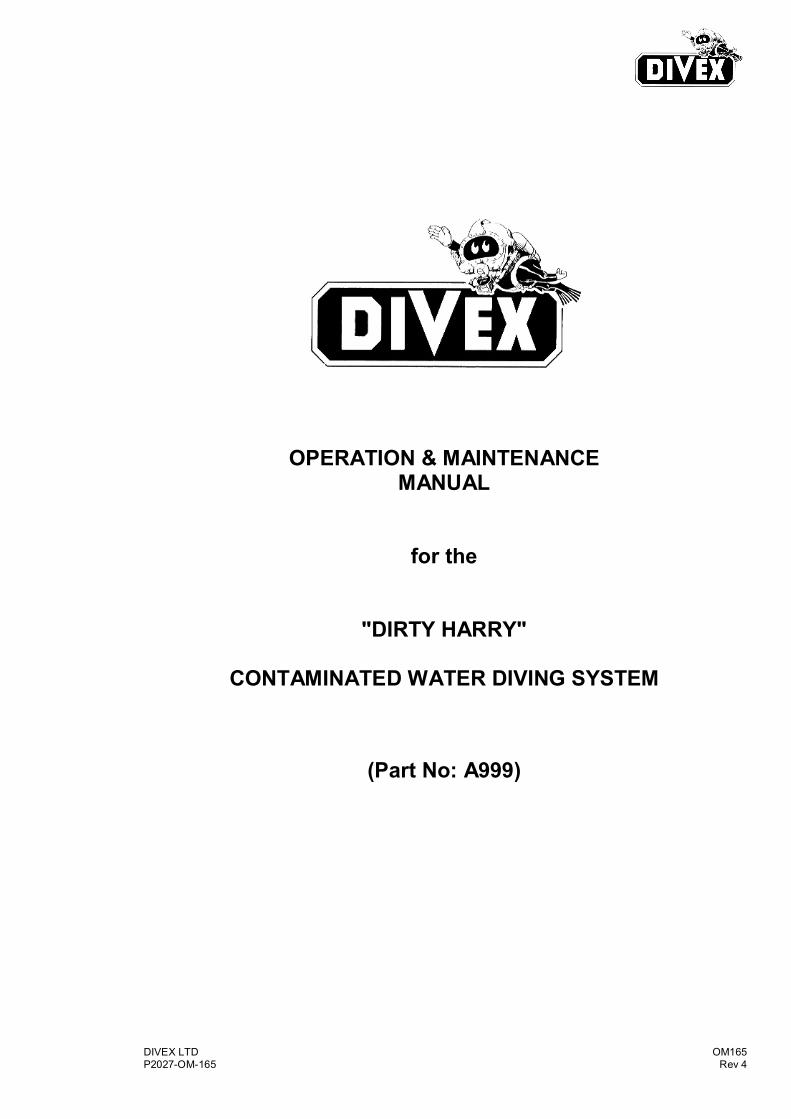
DIVEX LTD OM165 P2027-OM-165 Rev 4 OPERATION & MAINTENANCE MANUAL for the "DIRTY HARRY" CONTAMINATED WATER DIVING SYSTEM (Part No: A999)
DIVEX LTD OM165 P2027-OM-165 Rev 4
OPERATION & MAINTENANCE MANUAL
for the
"DIRTY HARRY"
CONTAMINATED WATER DIVING SYSTEM
(Part No: A999)
DIVEX LTD OM165 P2027-OM-165 Rev 4
THIS PAGE IS LEFT BLANK INTENTIONALLY

DIVEX LTD OM165 P2027-OM-165 i Rev 4
DIVEX LTD
DOCUMENT NUMBER: P2027-OM-165 DOCUMENT TITLE: OPERATION & MAINTENANCE MANUAL for the "DIRTY HARRY" CONTAMINATED WATER DIVING SYSTEM
REV DATE BY CHK APP COMMENTS
0
25/06/96 D. Austin A. Ransom D. Smith ORIGINAL ISSUE
1
23/09/03 L. Leckie W. Crosby W. Crosby ECN 4519
2
8/02/10 C. Crawford S. Waddell S. Waddell ECN 13235
3
19/03/10 C. Crawford S. Waddell S. Waddell ECN 13336
4
24/03/10 S. McMasters C. Crawford C. Crawford ECN 13343
5
6
7
ORIGINAL ISSUE DATE: 25th June 1996 ORIGINAL DOCUMENT BY: D. Austin CHECKED BY: A. Ransom APPROVED BY: D. Smith

DIVEX LTD OM165 P2027-OM-165 ii Rev 4
THIS PAGE IS LEFT BLANK INTENTIONALLY
DIVEX LTD OM165 P2027-OM-165 iii Rev 4
I N D E X
Document Control Sheet i Contents Page iii
1.0 INTRODUCTION
2.0 GENERAL DESCRIPTION & FUNCTION
2.1 Dirty Harry Helmet Assembly
2.2 Vacuum Exhaust Control Panel
2.3 Umbilical
2.3.1. Umbilical Care & Maintenance
2.4 “Dirty Harry” Dry suit
2.5 System Interconnects & Operation
2.5.1. Piping Connections / Hose Sizes
2.5.2. G.A. System Drawing
2.5.3. System Operation
2.5.3.1. Pre-Dive Procedure
2.5.3.2. Diving Operation Procedures
2.5.4. Post Dive Procedures
2.6 DIRTY HARRY DRY SUIT SERVICE/MAINTENANCE
2.6.1. Decontamination
2.6.2. Service and Maintenance
2.6.3. Storage
2.7 17C ULTRAJEWEL 601 AIR DIVE HELMET OPERATIONS &
MAINTENANCE MANUAL Part No. OM056
2.8 EXHAUST CONTROL PANEL SERVICE/MAINTENANCE
MANUAL Part No. OM161
3.0 SURFACE SUPPLY PANEL REQUIREMENTS
DIVEX LTD OM165 P2027-OM-165 iv Rev 4
THIS PAGE IS LEFT BLANK INTENTIONALLY

DIVEX LTD Page 1-1 OM165 P2027-OM-165 Rev 4
1.0 INTRODUCTION The “Dirty Harry” closed circuit diving system is designed to provide a safe and
efficient surface supplied system which minimises the risk of contact between the diver and the water in which he is diving.
The basic method of achieving this is by providing a bonded suit and helmet and
closed circuit breathing system whereby the divers exhausted air is returned to the surface and prevented from bubbling into the water.
To achieve this, a variation of the proven Divex reclaim helmet is used in
conjunction with a Vacuum Exhaust Control Panel, Umbilical and a “Dirty Harry” Dry Suit.
A surface Supply Panel is also required which can be supplied by Divex in addition to A999.
NOTE: The “Dirty Harry” system is designed to minimise contact between
the diver and his diving environment. It is the responsibility of the end user to assess the nature of this environment and the material suitability of the “Dirty Harry” equipment for use in potentially contaminated waters. Full material specifications of Divex “Dirty Harry” components are available on request.
DIVEX LTD Page 1-2 OM165 P2027-OM-165 Rev 4
THIS PAGE IS LEFT BLANK INTENTIONALLY
DIVEX LTD Page 2-1 OM165 P2027-OM-165 Rev 4
2.0 GENERAL DESCRIPTION & FUNCTION 2.1 Dirty Harry Helmet Assembly The Dirty Harry reclaim helmet (17C) consists principally of the Divex
ULTRAFLOW 601 demand regulator and DIRTY HARRY exhaust reclaim regulator fitted to a conventional SUPERLITE 17C Helmet.
The helmet is designed to provide fully closed-circuit demand and exhaust
functions which minimise the risk of water from the diving environment entering the divers helmet.
The helmet neck ring is pre-attached to the “Dirty Harry” suit (see Section 2.6) to
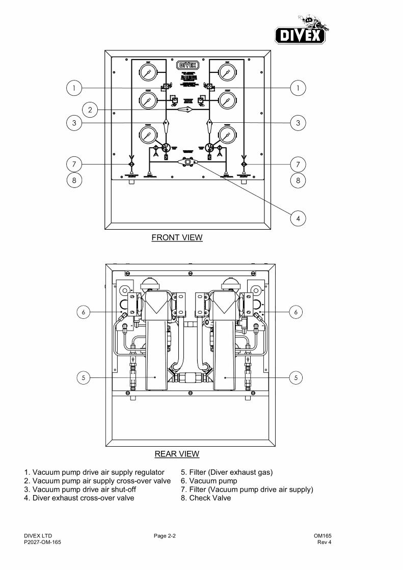
prevent potential water ingress at the neckseal area. 2.2 Vacuum Exhaust Control Panel The Vacuum Exhaust Control Panel provides a suction to the exhaust valve on
the Dirty Harry helmet ensuring the divers exhaled air is ducted away from the diver to the surface at depths where the hydrostatic pressure will be insufficient to vent exhaled gas unaided to the surface.
The exhaust control panel is required from the divers entry to the water to a depth
of approximately 6 metres depending on umbilical length. The panel is required to be used at these depths both on ascent and descent.
The two independent vacuum pumps are powered by high pressure compressed
air (as this is normally available on a dive site). The 50-205 Bar air supply required is regulated by a balanced 1st stage type regulator to provide a constant working supply. Approximately 450 - 500 SLPM (16 SCFM) of air is required per diver to provide suction via the pump to ensure the diver’s exhalation resistance complies within the HSE(NPD) work of Breathing Guidelines of up to 75 RMV at up to 10MSW.
The panel is constructed of stainless steel and other low corrosion components
and is furnished with all necessary filtration, controls and gauges.
DIVEX LTD Page 2-2 OM165 P2027-OM-165 Rev 4
FRONT VIEW
REAR VIEW
1. Vacuum pump drive air supply regulator 2. Vacuum pump air supply cross-over valve 3. Vacuum pump drive air shut-off 4. Diver exhaust cross-over valve
5. Filter (Diver exhaust gas) 6. Vacuum pump 7. Filter (Vacuum pump drive air supply) 8. Check Valve

DIVEX LTD Page 2-3 OM165 P2027-OM-165 Rev 4
2.3 Umbilical The “Dirty Harry” umbilical is constructed from the following components twisted together over approximately 70 metres of the length of the umbilical with only the ends being separate.:-
5/8” Exhaust Hose (Vacuum) 3/8” Air Supply Hose 1/4” Pneumofathometer Hose 4-Core (0.5mm2) Communications Cable
The cross-sectional diagram of the umbilical is shown below (Figure 1).
The standard umbilical (P/N PP070754SFBA) is 75 metres long and features the following connections at the surface end:- Surface End Diver End Pneumo Hose ¼” BSP Female Unterminated Air Supply Hose 3/8” BSP Female 6 JIC Female Exhaust / Reclaim Hose 10 JIC Female 8 JIC Female Communications Cable Simplex Connector 4 Socket RMG Connector Variants available include, but are not limited to, different lengths, JIC fittings on Air Supply and Pneumo Hose and Universal, AGA and EXO/DSI Comms connectors.
2.3.1. Umbilical Care & Maintenance
1. Do not use or store in the vicinity of sharp objects 2. Ensure umbilical is not kinked in use or storage 3. Do not crush, take care with heavy vehicles and equipment 4. Ensure the BSP and JIC connections are kept clean and lightly lubricated with
Christolube or similar. 5. Plug ends when not in use. 6. Clean thoroughly after use and purge with breathing quality air.

DIVEX LTD Page 2-4 OM165 P2027-OM-165 Rev 4
2.4 “Dirty Harry” Dry suit The “Dirty Harry” Dry Suit is constructed of durable polyurethane (other
materials available) and fitted with latex rubber cuff seals and natural rubber boots.
The helmet neck ring is mechanically bonded to a neck yoke piece thereby
forming an integral part of the suit. The suit is fitted with one inflation and two exhaust valves. The exhaust valves
are fitted for safety reasons to avoid suit over-inflation and uncontrolled ascent, if for any reason one of the valves ceased functioning.
2.5 System Interconnects & Operation
2.5.1. Piping Connections / Hose Sizes
The following interconnects are required for system operation:-
Exhaust Control Panel Umbilical Connection - 10JIC Exhaust Control Panel Vacuum Pump HP Supply - 4JIC, 205 bar swp Helmet Air Supply Connection - 8 JIC Helmet Exhaust Supply Connection - 8 JIC Helmet Bailout Connection – 9/16” UNF O-Ring seal Communications Surface Connection - Banana Plug Communications Diver Connection - 4 Pin RMG Connector
2.5.2. G.A. System Drawing

DIVEX LTD Page 2-5 OM165 P2027-OM-165 Rev 4
2.5.3. System Operation
2.5.3.1. Pre-Dive Procedure Referring to the “2-diver exhaust vacuum supply panel” drawing (section 2.2)
ensure vacuum pump air supply cross-over valve (item 2) and the diver exhaust cross-over valve (item 4) are both closed. Connect HP air supply 1/4” hose with a No.4 JIC female connection to each “Vacuum Pump Drive Air Supply” connection on the control panel. The 5/8” divers exhaust umbilicals should be connected to the connections marked Diver 1 exhaust umbilical and Diver 2 exhaust umbilical (No.10 JIC).
The HP air supply to the vacuum pump should be clean, filtered, breathing
quality air. This can be either HP air cylinders (205 bar/3000 psi) or HP compressor (205 bar/3000 psi) - the drive air supply regulators are protected by inline filters (item 7).
The divers exhaust umbilicals are connected to the helmet exhaust regulator
connections via a one metre (39 inches) long flexible whip (Part No. C1506B). To aid the divers head movement this hose has an ‘O’ ring swivel adaptor to allow the exhaust hose to rotate even with full vacuum.
2.5.3.2. Diving Operation Procedures 2-Diver Operations Open the supply valve from HP supply or supplies for the vacuum drive air
supplies. The regulators are pre-set, check both outlet pressures read 87-100psi (6.0 – 6.9 bar). The vacuum gauge should read greater than -0.5 bar (-14.75 ”Hg).
The system is now set-up for air diving operations including from the surface
down to 6 metres (20 feet). NOTE: If using HP air cylinders the supply pressure should be monitored
during the duration of the dive so that a fresh HP cylinder can be connected in time without loss of suction.
After an extended dive at depths shallower than 6 metres (20 feet) the
attendant should drain water from the filter housings. Due to the vacuum holding the check valve shut this operation is to be carried out after diving is completed.
Shut off the vacuum drive air supply and disconnect the exhaust hose at the
helmet swivel connector to release the vacuum, the check valve assembly is under the filter housing a pull cord is pulled down for a few seconds to drain water.

DIVEX LTD Page 2-6 OM165 P2027-OM-165 Rev 4
Divers exhaled breath contains moisture droplets, the coalescing filter elements in this system will remove this moisture. At depths greater than 6 metres (20 feet) the exhaust check valve will open automatically and the filter units will self drain.
When continuously diving at depths greater than 6 metres (20 feet). the
vacuum drive air system may be shut-off to save the vacuum drive air. Vacuum assistance is not required beyond 6 metres (20 feet), as the pressure differential from the diver at this depth in relation to the surface pressure is adequate to provide sufficient suction.
When the diver is returning to the surface, the attendant should turn on the
vacuum system before 6 metres (20 feet). If a temporary loss of vacuum drive air supply to one vacuum pump is
anticipated, (e.g. while changing HP cylinders) the vacuum pump supply cross-over valve (item 2) is opened to allow both vacuum pumps to be driven by one air regulator.
NOTE: A check valve is fitted to each drive air supply circuit so that
either HP hose can be drained during diving operations. If a loss of vacuum occurs to one of the divers during a dive and the vacuum
drive air supply is still correctly set to 87-100 psi (6.0 – 6.9 bar), then the diver exhaust cross-over valve (item 4) is opened so that both divers can share one vacuum pump.
One Diver Operations: The above procedure is the same for one diver operations, it is good practice
to leave both HP supplies connected to allow the safety feature of the cross-over valves to be used in the event of any problems occurring, additionally the system will be ready for a back-up diver to remain on stand-by.
2.5.4. Post Dive Procedures In clean freshwater diving conditions the two filter bowls (item 5) should be
removed (unscrewed) and rinsed weekly in clean fresh water. Particular attention should be paid during seawater diving operations as the filter body is made from aluminium alloy and may corrode with prolonged seawater contact. Depending upon the diving environment this may require to be done daily.
Cleaning the panel to remove seawater spray or other contaminants using fresh
water at the end of the days diving will help prevent corrosion, however, the housing is made from stainless steel and should remain bright if kept clean.
The helmet should be inspected - maintained in accordance with the helmet
manual.

DIVEX LTD Page 2-7 OM165 P2027-OM-165 Rev 4
2.6 DIRTY HARRY DRY SUIT SERVICE/MAINTENANCE All Dirty Harry dry suits are required to be decontaminated before removal by the diver and any service or maintenance is carried either by the user or Divex Limited.
DIRTY HARRY DRY SUIT
SERVICE/MAINTENANCE
DIVEX LTD Page 2-8 OM165 P2027-OM-165 Rev 4
2.6.1. Decontamination
When a dry suit has been used in a hazardous environment, decontamination should be carried out immediately after use and at the work location. This should be carried out before doffing by the diver to prevent any possible risk to health. The users technical/medical representative is to specify the cleaning procedure most suitable for the level of contamination and the type of chemical that the suit has been exposed to. In the absence of specific instructions from the technical/medical representative the minimum level of decontamination shall consist of showering or spraying the suit with clean water and lightly scrubbing with a soft bristle brush using a recommended mild detergent, then thoroughly rinsing in clean water. Both the diver and the cleaning operators health and safety are to be considered before carrying out any decontamination procedure. After suitable decontamination the suit can be removed and inspected for future use. An assessment is required to determine if the suit can be re-used or additional decontamination is required.
2.6.2. Service and Maintenance
After use the dry suit is to be cleaned and inspected in accordance with the following instructions: 1. Inspect the entire suit for any signs of damage paying particular attention to
the seals and zips, if signs of damage are found the suit is to be scrapped or returned to Divex for further inspection and possible repair.
Inspection should pay particular attention to signs of brittleness/hardening of the suit material, changes in colour and swelling of the material. If in doubt discard the suit or return to Divex for further examination.
Caution: if the dry suit is to be returned to Divex Limited then the user is to certify that the suit has been decontaminated and is safe to be handled. 2. Rinse the suit and seals thoroughly with clean water paying particular attention
to the zip. Using a small stiff bristle brush e.g. toothbrush, brush the zip from base to tip of the teeth.
3. Hang full length in a warm dry environment at 25 deg. C max, keeping all
metallic objects away from the seals. Leave until thoroughly dry. Caution: Store out of direct sunlight and harsh artificial lighting as damage can occur to the seals.

DIVEX LTD Page 2-9 OM165 P2027-OM-165 Rev 4
2.6.3. Storage
When completely dry lightly talc the seals with French chalk or baby powder. Ensure that the zip is thoroughly clean and undamaged then lubricate with zipper ease or zip glide. Store the suit as described above or pack away in the original packing provided. Warning to users: Do not wear any perfumed lotions, sprays or aftershave next to the seals nor wear any jewellery or sharp objects which could damage the dry suit material. It is the responsibility of the user to ensure that the suit is suitable for the intended environment that it is to be used in and that suitable and adequate decontamination information is available prior to commencing any diving operations.

DIVEX LTD Page 2-10 OM165 P2027-OM-165 Rev 4
PAGE INTENTIONALLY LEFT BLANK

DIVEX LTD Page 2-11 OM165 P2027-OM-165 Rev 4
2.7 17C ULTRAJEWEL 601 AIR DIVE HELMET OPERATIONS & MAINTENANCE MANUAL Part No. OM056
17C ULTRAJEWEL 601 AIR DIVE HELMET OPERATIONS & MAINTENANCE
MANUAL
Part No. OM056

DIVEX LTD Page 2-12 OM165 P2027-OM-165 Rev 4
PAGE INTENTIONALLY LEFT BLANK
DIVEX LTD Page 2-13 OM165 P2027-OM-165 Rev 4
2.8 EXHAUST CONTROL PANEL SERVICE/MAINTENANCE MANUAL Part No. OM161
EXHAUST CONTROL PANEL SERVICE/MAINTENANCE
MANUAL
Part No. OM161

DIVEX LTD Page 2-14 OM165 P2027-OM-165 Rev 4
PAGE INTENTIONALLY LEFT BLANK

DIVEX LTD Page 3-1 OM165 P2027-OM-165 Rev 4
3.0 SURFACE SUPPLY PANEL REQUIREMENTS
A suitable portable diver gas supply panel is required which will accept supplies from four high pressure sources and one low pressure back-up source to support two divers in the water. Divers depth should be monitored via independent depth gauges. Communications permitting diver to surface and diver to diver two-way communications should be provided.
Supplies required are:
HP Air Source, 350 Bar Max WP x 4 LP Air Source, 20 Bar Max WP x 1
Services provided:
HP Supply Pressure Indication x 2 Low HP Warning @ 50 Bar LP Supply Pressure Indication x 2 Diver Outlets x 2 Diver Pneumo x 2 Diver Communications x 2
Divex can provide a suitable panel on request. For example PP032** (eg. PP032AA) type panels provide facilities for Air Supply and Communications. PP033** type panels provide facilities for Air Supply.


