84
OPERATION / MAINTENANCE MANUAL 7032 SOUTH 196th - KENT, WA. 98032 - (253) 872-0141 / FAX (253) 872-8710 MODEL HD70 HELICAL PILE DRILL MODEL HD70 HELICAL PILE DRILL SERIAL NUMBER:

OPERATION / MAINTENANCE MANUAL
7032 SOUTH 196th - KENT, WA. 98032 - (253) 872-0141 / FAX (253) 872-8710
MODEL HD70 HELICAL PILE DRILL
MODEL HD70 HELICAL PILE DRILL
SERIAL NUMBER:

OPERATION / MAINTENANCE MANUAL
7032 SOUTH 196th - KENT, WA. 98032 - (253) 872-0141 / FAX (253) 872-8710
MODEL HD70 HELICAL PILE DRILL

OPERATION / MAINTENANCE MANUAL
7032 SOUTH 196th - KENT, WA. 98032 - (253) 872-0141 / FAX (253) 872-8710
MODEL HD70 HELICAL PILE DRILL
ChangeNumber
PageNumber Date Revision Description
Revision Record
Page i
6-2013 INITIAL PRINTING

OPERATION / MAINTENANCE MANUAL
7032 SOUTH 196th - KENT, WA. 98032 - (253) 872-0141 / FAX (253) 872-8710
MODEL HD70 HELICAL PILE DRILL
Preface
General
This manual covers the Model HD70 Helical Pile Drill. The data provided in this manual gives the necessary information to operate and maintain APE equipment. The listed procedures are to be performed by qualifi ed personnel who have an understanding of the equipment and who follow all safety precautions.
Guide to Using the Manual
1. Refer to the Table of Contents for the page location of applicable sections.
2. All weights and measurements in this manual are in both English and Metric units.
3. The manual will be revised as necessary to refl ect current information.
Page ii

OPERATION / MAINTENANCE MANUAL
7032 SOUTH 196th - KENT, WA. 98032 - (253) 872-0141 / FAX (253) 872-8710
MODEL HD70 HELICAL PILE DRILL
Table of Contents Page
Revision Record .................................................................................................... i Preface ................................................................................................................... ii Table of Contents .................................................................................................. iii-iv Safety Precautions ................................................................................................ v Warranty ................................................................................................................ vii
I. GENERAL INFORMATION I-1. Machine Features HD70 Helical Plie Drill ................................................ 1-2 I-2. Machine Specifi cations ............................................................................... 1-3 I-3. General Description of HD70 Helical Plie Drill ........................................... 1-4 A. Lifting Bale ........................................................................................... 1-5 B. Grouting System .................................................................................. 1-6 C. Drill Housing ......................................................................................... 1-7 D. Drive Socket ......................................................................................... 1-8 E. Clamp ................................................................................................... 1-9
II. PREPARATION AND OPERATION II-1. General ....................................................................................................... 2-2 II-2. Rigging of Helical Pile Driver ...................................................................... 2-2 II-3. Connection of Hydraulic Clamp .................................................................. 2-2 II-4. Connection of Hydraulic Hoses .................................................................. 2-3 II-5. Port Identifi cation of Drill Manifold .............................................................. 2-4 II-6. Motor Port Identifi cation .............................................................................. 2-5 II-7. Filling Drill Motor Hoses .............................................................................. 2-5
III. OPERATING INSTRUCTIONS Drill Speed, Clamp and Rotation Control Figures .................................................... 3-1 III-1 Drill Speed, Clamp and Rotation Controls .................................................. 3-2 III-2. Warming Hydraulic Fluid ............................................................................. 3-3
IV. MAINTENANCE AND ADJUSTMENTS IV-1. General ....................................................................................................... 4-1 IV-2. Daily ............................................................................................................ 4-1 IV-3. Bolt Torque Information............................................................................... 4-3
V. OPERATING INSTRUCTIONS V-1 Hydraulic Clamp ......................................................................................... 5-1 V-2. Main Drive .................................................................................................. 5-1 Hydraulic Schematic ................................................................................... 5-2 V-3. Hydraulic Components List ......................................................................... 5-3 Hydraulic Schematic Drill Manifold ............................................................. 5-4 Hydraulic Schematic Drill Interlock Manifold .............................................. 5-5 Hydraulic Schematic Clamp Manifold ......................................................... 5-6
VI. GENERAL DATA VI-1. Abbreviation ................................................................................................ 6-1 VI-2. Screw and Bolts .......................................................................................... 6-1 VI-3. Serial Number Locations ............................................................................ 6-2
Page iii

OPERATION / MAINTENANCE MANUAL
7032 SOUTH 196th - KENT, WA. 98032 - (253) 872-0141 / FAX (253) 872-8710
MODEL HD70 HELICAL PILE DRILL
VII. ORDERING PARTS VII-1. Procedure ................................................................................................... 7-1 VII-2. Fitting Description Key ................................................................................ 7-2 VII-3. Fitting Style Selector Chart ......................................................................... 7-3 VII-4. Hose Description Code ............................................................................... 7-4 VII-5. Parts Identifi cation ...................................................................................... 7-5 VII-6. Helical Pile Drill ........................................................................................... 7-6 VI-7 Drill Housing ............................................................................................... 7-8 VI-8 Drill Motor ................................................................................................... 7-10 VI-9 Clamp Housing ........................................................................................... 7-12 VI-10 Clamp Cylinder ........................................................................................... 7-14 VI-11 Clamp Manifold ........................................................................................... 7-16 VI-12 Jaw Options ................................................................................................ 7-18 VI-13 Top Plate ..................................................................................................... 7-20 VI-14 Bale ............................................................................................................ 7-22 VI-15 Pin ............................................................................................................. 7-24 VI-16 Drive Socket ............................................................................................... 7-26 VI-17 Socket Retainer .......................................................................................... 7-28 VI-18 Grouting ...................................................................................................... 7-30 VI-19 Grout Plug .................................................................................................. 7-32 VI-20 Blank Plate ................................................................................................. 7-34 VI-21 Drill Manifold ............................................................................................... 7-36 VI-22 Interlock Manifold ....................................................................................... 7-38 VI-23 Accumulator ................................................................................................ 7-40 VI-24 Safety Gate ................................................................................................. 7-42 VII-25. Recommended Bolt Tightening Torque....................................................... 7-45
Page iv

OPERATION / MAINTENANCE MANUAL
7032 SOUTH 196th - KENT, WA. 98032 - (253) 872-0141 / FAX (253) 872-8710
MODEL HD70 HELICAL PILE DRILL
Safety Precautions(This list of precautions must be followed at all times to ensure personal & equipment safety.)
1. Read this manual from beginning to end before operating or working on this machine.
2. When operating in a closed area, pipe exhaust fumes outside. (WARNING: Breathing exhaust fumes can cause serious injury and even death.)
3. When servicing batteries, avoid any type of spark or open fl ame. Batteries generate explosive gases during charging. There must be proper ventilation when charging batteries.
4. Never Adjust or repair the unit while it is in operation.
5. Remove all tools and electrical cords before starting the unit.
6. Keep oily rags away from the exhaust system.
7. Never store fl ammable liquids near the engine.
8. Never stand under driver at any time and keep your eyes on the driver when it is in operation. Keep a look out for loose bolts or leaking hydraulic lines.
9. Avoid pulling on hose quick dis-connect fi ttings. Use unit closer to work if hoses cannot reach. Do not use hoses as a tow line! If a hose fails at the hydraulic couplers then it is a result of "hose tugging by the pile crew".
10. Avoid kinks in the hoses. Kinks will cut the hose safety factor by 50 percent.
11. Always wear eye and ear protection.
12. Avoid standing downwind of rotating piles. Dirt and other matter may become airborne and fall into the unprotected eye.
13. Always wear a hardhat, gloves, and safety shoes.
14. Do not truck power unit with quick disconnect caps and plugs screwed on to fi ttings unless the caps and plugs have wire rope safety lines attached. Store in storage box under control panel.
Page v

OPERATION / MAINTENANCE MANUAL
7032 SOUTH 196th - KENT, WA. 98032 - (253) 872-0141 / FAX (253) 872-8710
MODEL HD70 HELICAL PILE DRILL
Page vi

OPERATION / MAINTENANCE MANUAL
7032 SOUTH 196th - KENT, WA. 98032 - (253) 872-0141 / FAX (253) 872-8710
MODEL HD70 HELICAL PILE DRILL
WarrantyAmerican Piledriving Equipment, Inc.
STANDARD WARRANTY
American Piledriving Equipment, Inc. (APE/J&M) warrants new products sold by it to be free from defects in material or workmanship for a period of one year after the
date of delivery to the fi rst user and subject to the following conditions:APE/J&M’s obligation and liability under this WARRANTY is expressly limited to repairing or replacing
at APE/J&M’s option, any parts which appear to APE/J&M upon inspection to have been defective in material or workmanship. Such parts shall be provided at
no cost to the user, at the business establishment of APE/J&M or the authorized APE/J&M distributor of the product during regular working hours. This WARRANTY, shall not apply to component
parts or accessories of products not manufactured by APE/J&M and which carry the warranty of the manufacturer thereof, or to normal maintenance (scraped and skived lube and fuel lines, worn cushion material in the drive base) or normal maintenance parts (such as fouled injectors, weakened check valve
springs, damaged grease fi ttings caused by use over time). Replacement or repair parts installed in the product covered by this WARRANTY are warranted only for
the remainder of the warranty as if such parts were original components of said product. APE/J&M makes no other warranty, expressed or implied and makes no
warranty of merchantability of fi tness for any particular purpose.
APE’s obligation under this WARRANTY shall not include any transportation charges, costs of installation, duty, taxes or any other charges whatsoever, or any liability for direct, indirect,
incidental or consequential damage or delay. If requested by APE/J&M, products or parts for which a warranty claim is made are to be returned transportation prepaid to APE/J&M. Any improper use, includ-ing operation after discovery of defective or worn parts, operation beyond rated capacity, substitution
of any parts whatsoever, or parts not approved by APE/J&M or any alteration or repair by others in such manner as in APE/J&M’s judgment affects the product materially and
adversely, shall void this warranty.
ANY TYPE OF WELDING ON EQUIPMENT WILL VOID THE WARRANTY
Refusal: Vibros: If the pile does not move one foot in 30 seconds of vibro operation at full speed. Resort toa larger vibro. APE/J&M equipment may exceed the refusal driving criteria for short periods of time as may be needed
to penetrate hard soil layers or obstacles. In such cases, a heat gun is used to monitor the temperature of the bearings and related components to prevent use of the machine beyond 210 degrees F. Contact APE/J&M or your local
APE/J&M distributor for special instructions when faced with refusal conditions.Refusal: Diesels: Do not exceed 10 blows per inch or 120 blows per foot. In cases of setting of the pile it ispermitted to increase the blow count to 250 blows per foot, but only for one foot of driving penetration. Pile
inspectors should consult the APE factory for permission to exceed these limits. Failure to do so will void thewarranty. This standard specifi cation is accepted by the DFI (Deep Foundations Institute) and the PDCA
(Pile Driving Contractors Association) and by all manufacturers of pile driving equipment.
Page vii

OPERATION / MAINTENANCE MANUAL
7032 SOUTH 196th - KENT, WA. 98032 - (253) 872-0141 / FAX (253) 872-8710
MODEL HD70 HELICAL PILE DRILL
Page 1-2
Bale Assembly is modular and can be removed to reduce weight and height.
Grout post installation wi th APE patented breakthrough push out tip.
Clamp manifold assembly simplifi es the centering of pile.
D isp lacement Sh i f t Interlock Manifold controls speed and motor case fl ushing.
Fork Lift slots allow additional options.
Heavy duty cylinder needs no guards and all hoses are tucked out of harms way.
Through Hole Grout System.
I-1. Machine Features - Model HD70 Helical Pile Drill
Figure 1-A. Machine Features
The heavy duty lifting pin allows easy rigging of the driver to excavator to ensure maximum safety.
Hydrau l ic motor is recessed in the drill housing to be ful ly protected.
Drill Manifold regulates maximum pressure to the motor as well as protect it from cavitating.
C lamp Hous ing i s designed to maintain good pile alignment.
Jaws made to fi t specifi c size pile.
Safety catch system.

OPERATION / MAINTENANCE MANUAL
7032 SOUTH 196th - KENT, WA. 98032 - (253) 872-0141 / FAX (253) 872-8710
MODEL HD70 HELICAL PILE DRILL
Page 1- 3
I. GENERAL INFORMATION
I-2. Machine Specifi cations
Model HD70
Recomended Excavator CAT 320E is the bare minimum330 Class is a better with no quick coupler349 Class maximum size with quick coupler
Table 1-A. - Drill
Torque Low SpeedTorque High SpeedDrill Speed "Low"Drill Speed "High"Max. Hydraulic FlowMax. Hydraulic PressureWeight (with Clamp)HeightWidthDepth
56,300ft-lbs (76,332Nm)16,600ft-lbs (22,507Nm)
30 rpm45 rpm
120 gpm (454 lpm)4,641 psi (320 bar)
8,440 lbs (3,828 kg)99" (2,515 mm)61" (1,549 mm)
25" (635 mm)
Model HD70

OPERATION / MAINTENANCE MANUAL
7032 SOUTH 196th - KENT, WA. 98032 - (253) 872-0141 / FAX (253) 872-8710
MODEL HD70 HELICAL PILE DRILL
Page 1-4
I. GENERAL INFORMATION
I-3. General Description of Model HD70
The APE Model HD70 is a variable speed helical pile driver designed to drive and extract all APE helical piles sizes 4.5 to 13.375. All of which can be grouted.
The fi ve major parts to the Model HD70 are as follows:
A.) Lifting Bale B.) Grouting System C.) Drill Housing D.) Drive Socket E.) Clamp
Figure 1-B. General Description of HD70.
A. LIFTING BALE
B. GROUTING SYSTEM
C. DRILL HOUSING
D. DRIVE SOCKET
E. CLAMP

OPERATION / MAINTENANCE MANUAL
7032 SOUTH 196th - KENT, WA. 98032 - (253) 872-0141 / FAX (253) 872-8710
MODEL HD70 HELICAL PILE DRILL
Page 1- 5
I. GENERAL INFORMATION
I-3A. Lifting Bale
The lifting bale is shipped to accommodate excavators with a bucket pin diameter as small as 2.75 (70 mm) and as wide as 17.75 (450 mm). Bushings are used to fi t the lifting bale to the excavator. The lifting bale allows the HD70 to hang the helical pile plumb to start and allows the operator to keep it plumb while driving (installing) pile.
Figure 1-C. General Description of Lifting Bale
Excavator Pin
Lifting Bale Asm
Pivot Pin Asm
Top Plate Asm

OPERATION / MAINTENANCE MANUAL
7032 SOUTH 196th - KENT, WA. 98032 - (253) 872-0141 / FAX (253) 872-8710
MODEL HD70 HELICAL PILE DRILL
Page 1-6
I. GENERAL INFORMATION Continued
I-3B. Grouting System
The grouting system allows full depth soil mix grouting through the tip of the pile. The grout swivel allows the grout to be pumped while the pile is being driven (inserted) through a system that keeps the grout from harming any other components of the HD70 or other surroundings. The grout cover plate, auger shaft sleeve, oil seal carrier, motor end plate along with other items continue the link of mechanisms of pumping grout through the system including the hydraulic motor without grout leakage.The Model HD70 can be operated under water with slight modifi cations. (Consult factory for modifi cations)
Figure 1-D. General Description of Grouting System
Grout Cover Plate
Auger Shaft Sleeve
Oil Seal Carrier
Motor End Plate
Grout Swivel

OPERATION / MAINTENANCE MANUAL
7032 SOUTH 196th - KENT, WA. 98032 - (253) 872-0141 / FAX (253) 872-8710
MODEL HD70 HELICAL PILE DRILL
Page 1- 7
I. GENERAL INFORMATION Continued
I-3C. Drill Housing
The APE HD70 drill housing is the main body which contains many key components. The hydraulic motor along with a square drive, a tapered roller bearing, bushings and a grout stem are bolted in. A hose block assembly as well as the drill manifold, DSI and clamp manifold assemblies are bolted in. There are several covers and brackets bolted to the outside of the drill housing.
Figure 1-E. General Description of Drill Housing

OPERATION / MAINTENANCE MANUAL
7032 SOUTH 196th - KENT, WA. 98032 - (253) 872-0141 / FAX (253) 872-8710
MODEL HD70 HELICAL PILE DRILL
Page 1-8
I. GENERAL INFORMATION Continued
I-3D. Drive Socket
The APE HD70 drive socket is the system that transfers the hydraulic motor rotation into the fl ighting system. Adapting the hydraulic motor into a standard square drive into the needed size drive socket of the pile. The drive socket has a through hole to allow grouting.
Figure 1-F. General Description of Drive Socket
OPERATION / MAINTENANCE MANUAL
7032 SOUTH 196th - KENT, WA. 98032 - (253) 872-0141 / FAX (253) 872-8710
MODEL HD70 HELICAL PILE DRILL
Page 1- 9
Cylinder EndCover Cylinder housing
Jaw
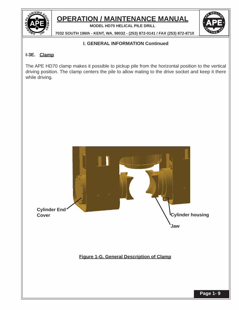
Figure 1-G. General Description of Clamp
I. GENERAL INFORMATION Continued
I-3E. Clamp
The APE HD70 clamp makes it possible to pickup pile from the horizontal position to the vertical driving position. The clamp centers the pile to allow mating to the drive socket and keep it there while driving.
OPERATION / MAINTENANCE MANUAL
7032 SOUTH 196th - KENT, WA. 98032 - (253) 872-0141 / FAX (253) 872-8710
MODEL HD70 HELICAL PILE DRILL
Page 2-2
II. PREPARATION FOR OPERATION
II-1. General
When unloading and unpacking the helical pile driver, use extreme care. For your protection, make a thorough inspection of the unit immediately on delivery. In case of any damage or shortage, notify the transit agent at once and have the delivering carrier make a notation on the freight bill.
II-2. Rigging of Helical Pile Driver
The lifting bale has a pin that will fi t in the stick of the excavator as a replacement of the bucket pin. This is done with the use of bushings that are sized to properly fi t the excavator being used. Once the bucket has been removed and the cylinder controlling the motion of the bucket is either removed or secured. The bucket cylinder is not used, but the hydraulic circuit will be used for the operation of the helical pile driver.
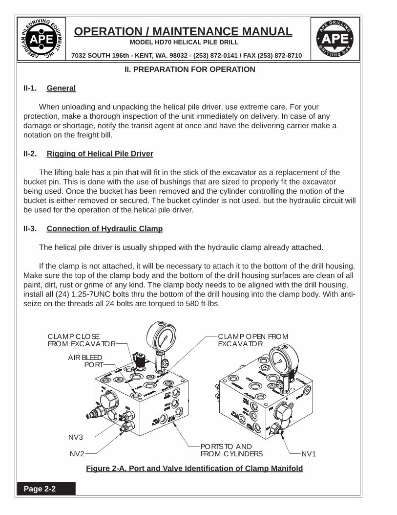
II-3. Connection of Hydraulic Clamp
The helical pile driver is usually shipped with the hydraulic clamp already attached.
If the clamp is not attached, it will be necessary to attach it to the bottom of the drill housing. Make sure the top of the clamp body and the bottom of the drill housing surfaces are clean of all paint, dirt, rust or grime of any kind. The clamp body needs to be aligned with the drill housing, install all (24) 1.25-7UNC bolts thru the bottom of the drill housing into the clamp body. With anti-seize on the threads all 24 bolts are torqued to 580 ft-lbs.
NV1NV2
NV3
AIR BLEED
PORTS TO AND
FROM EXCAVATORCLAMP CLOSE
FROM CYLINDERS
PORT
CLAMP OPEN FROMEXCAVATOR
Figure 2-A. Port and Valve Identifi cation of Clamp Manifold

OPERATION / MAINTENANCE MANUAL
7032 SOUTH 196th - KENT, WA. 98032 - (253) 872-0141 / FAX (253) 872-8710
MODEL HD70 HELICAL PILE DRILL
Page 2-3
II. PREPARATION FOR OPERATION
II-4. Connection of Hydraulic Hoses
The Clamp manifold is to be connected to the excavator's bucket circuit. Clamp Close should be connected to the "Curl Bucket" supply tube and the Clamp Open should be connected to the "Open Bucket" supply tube. Connect the four hoses from the clamp manifold to the fi ttings on the cylinders. The clamp open fi tting on the cylinder is the fi tting on the right when looking at the cylinder rod, the ports on the manifold are labeled respectably. Send oil to the open ports of the cylinders by using the hand control in the excavator. With clamps all the way open. Rotate one jaw 45 degrees to be sure jaw tips clear. A hose is provided to cleanly bleed the air from the cylinders connected to the AIR BLEED port on the clamp manifold. Place this hose into a bucket. Open valve NV2. Send oil to the close ports of the cylinders by using the hand control in excavator and close cylinders until fully extended, the air will be evacuated from the rod side of the cylinders. Close valve NV2. To bleed the remainder of the air in the clamp system open valves BV2 and BV3 which are mounted on the top of the cylinder. Close the jaws and hold joystick for a full 45 seconds. Close valves BV2 and BV3. This process puts the jaws in sync as well as bleeding the air. If the jaws become out of sync or action becomes spongy repeat this process.
The Drill Manifold is to be connected to the auxiliary circuit. The Forward FWD rotation fl ow from the excavator will be connected to the "A1" port and Reverse REV fl ow will be connected to the "B1" port. The port "A2" will connect to the "L" port on the motor and the port "B2" will be connected to the "R" port on the motor. A case drain hose will need to be run back to the excavator's hydraulic tank.
Clamp "OPEN" hose goes to the fi tting on the left and Clamp "CLOSE hoses goes to the fi tting on the right.
Figure 2-B. Clamp Cylinder Hose Locations

OPERATION / MAINTENANCE MANUAL
7032 SOUTH 196th - KENT, WA. 98032 - (253) 872-0141 / FAX (253) 872-8710
MODEL HD70 HELICAL PILE DRILL
Page 2-4
Figure 2-C. Drill Manifold Ports
"B1"REVERSE HOSEFROMEXCAVATOR
"A1"FORWARDHOSE FROMEXCAVATOR
II. MAJOR COMPONENT DEFINITION
II-5. Port Identifi cation of Drill Manifold
"A2"TO MOTORPORT "L"
"B2"TO MOTORPORT "R"

OPERATION / MAINTENANCE MANUAL
7032 SOUTH 196th - KENT, WA. 98032 - (253) 872-0141 / FAX (253) 872-8710
MODEL HD70 HELICAL PILE DRILL
Page 2-5
II. MAJOR COMPONENT DEFINITION
II-6. Motor Port Identifi cation
II-7. Filling Drill Motor Hoses
The Helical Pile Drill is usually shipped with the drill motor hoses full of fl uid and the unit may be used immediately. However, if the drive hoses have been removed from the drill motor, they will need to be fi lled before full speed operation.
1. The motor case is going to need to be fi lled by removing the top fi ll plug in port labeled "CD" and pouring in new clean hydraulic oil. Port CD is the connection for the case drain hose.
2. To fi ll the displacement shift hose with hydraulic oil. With the shift hose removed from the motor and placed in a bucket. Turn the knob on the Displacement Shift Valve (See Fig 3-A) CCW until it clicks. Hold the clamp close joystick (See Fig 3-A) in the close position and allow oil to fl ow clear of air. Release joystick turn the knob on displacement shift valve CW and install hose onto fi tting in Port Y.
3. This is the LOW speed position.4. With all hoses connected, run the excavator at low engine RPM and slowly push
the toggle on the left hand joystick FWD (See Fig 3-B). Continue to send this small amount of fl ow to the drill motor for 2 minutes. This will push the air that is present in the system through to have only oil in all of the hoses and motor.
NEVER shift speed if the drill motor is spinning!
Figure 2-D. Motor Ports

OPERATION / MAINTENANCE MANUAL
7032 SOUTH 196th - KENT, WA. 98032 - (253) 872-0141 / FAX (253) 872-8710
MODEL HD70 HELICAL PILE DRILL
Page 2-6
II. MAJOR COMPONENT DEFINITION
II-7. Filling Drill Motor Hoses (Continued)
5. Slowly switch the drill direction to REV by pulling back on the toggle on the left hand joystick and allow it to run for another 2 minutes.
6. Stop the rotation. Shift the manual "Displacement Shift Valve" to HIGH Speed7. Slowly push the toggle to FWD. Bring excavator to full engine RPM, allow the drill
motor for 2 minutes. Pull the toggle to REV to confi rm the drill motor will run in REV at full speed.
NEVER shift speed if the drill motor is spinning!

OPERATION / MAINTENANCE MANUAL
7032 SOUTH 196th - KENT, WA. 98032 - (253) 872-0141 / FAX (253) 872-8710
MODEL HD70 HELICAL PILE DRILL
Page 3-1
III. OPERATING INSTRUCTIONS
DRILL SPEED, CLAMP AND ROTATION CONTROLS
Figure 3-A. Clamp OPEN-CLOSE Control / Displacement Shift Valve
Figure 3-B. Drill Rotation Control Toggle
CLAMPOPEN-CLOSECONTROL
DISPLACEMENTSHIFT VALVE
TOGGLE

OPERATION / MAINTENANCE MANUAL
7032 SOUTH 196th - KENT, WA. 98032 - (253) 872-0141 / FAX (253) 872-8710
MODEL HD70 HELICAL PILE DRILL
Page 3-2
III. OPERATING INSTRUCTIONS
III-1. COMPLETION OF SET-UP AND MAINTENANCE
1. Complete all preparation as described in Section II.
2. Read Section IV - MAINTENANCE AND ADJUSTMENTS and perform any required maintenance.
III-2. DRILL SPEED, CLAMP AND ROTATION CONTROLS
1. The Displacement Shift Valve as shown in Figure 3-A controls the speed of rotation of the drill motor. Changing speed can ONLY be done when the drill motor is NOT rotating. With valve knob turned all the way clockwise in the forward position the drill motor will run in LOW-SPEED / HIGH TORQUE. While holding the clamp joystick in the close position turn the displacement shift valve knob counter clockwise until it clicks and stays in position. This will allow the drill motor run in HIGH-SPEED / LOW TORQUE.
2. The Clamp OPEN-CLOSE control is the Right hand joystick as shown in Figure 3-A. This control is replacing the use of the Bucket.
3. To close the clamp jaws. Pulling the Right hand joystick in to the LEFT “Curl Bucket” will close the clamp jaws.
4. To open the clamp jaws. Pushing the Right hand joystick out to the RIGHT “Open Bucket” will open the clamp jaws.
5. For drill rotation the Left hand joy stick has a toggle shown in Figure 3-B. Pushing the toggle forward will cause the drill to spin clockwise (CW). The farther the toggle is pushed the faster the drill RPM. Releasing the toggle stops the drill rotation.
6. Pulling the toggle backwards will cause the drill to spin counter clockwise (CCW). In the same fashion as CW the farther you pull the faster the drill RPM. Releasing the toggle stops the drill rotation.

OPERATION / MAINTENANCE MANUAL
7032 SOUTH 196th - KENT, WA. 98032 - (253) 872-0141 / FAX (253) 872-8710
MODEL HD70 HELICAL PILE DRILL
Page 3-3
III. OPERATING INSTRUCTIONS
III-3. WARMING HYDRAULIC FLUID
1. The helical pile drill should not be operated at full speed if the temperature of the hydraulic fl uid is below 70°F(21°C).
2. If temperature of the hydraulic fl uid is below 70°F(21°C), set the diesel engine at 1500 RPM and run the auger at reduced speed until the temperature of the hydraulic fl uid exceeds 70°F(21°C).
3. When the engine is warmed up and hydraulic fl uid temperature is at least 70°F(21°C), full speed operation may begin. Adjust the throttle so the engine is running at full engine RPM.
Do not operate the helical pile drill if hydraulic fl uid temperature exceeds 180°F(82°C) as this may damage hydraulic components.

OPERATION / MAINTENANCE MANUAL
7032 SOUTH 196th - KENT, WA. 98032 - (253) 872-0141 / FAX (253) 872-8710
MODEL HD70 HELICAL PILE DRILL
Page 3-4

OPERATION / MAINTENANCE MANUAL
7032 SOUTH 196th - KENT, WA. 98032 - (253) 872-0141 / FAX (253) 872-8710
MODEL HD70 HELICAL PILE DRILL
Page 4-1
IV. MAINTENANCE AND ADJUSTMENTS
IV-1. GENERAL
Preventive maintenance includes normal servicing that will keep the helical pile driver in peak operating condition and prevent unnecessary trouble from developing. This servicing consists of periodic lubrication and inspection of the moving parts and accessories of the unit.
Lubrication is an essential part of preventative maintenance, controlling to a great extent the useful life of the unit. Different lubricants are needed and some components in the unit require more frequent lubrication than others. Therefore, it is important that the instructions regarding types of lubricants and frequency of their applications be closely followed.
To prevent minor irregularities from developing into serious conditions that might involve shut-down and major repair, several other services or inspections are recommended for the same intervals as the periodic lubrications. The purpose of these services or inspections is to assure the uninterrupted operation of the unit.
Thoroughly clean all lubrication fi ttings, caps, fi ller and level plugs and their surrounding surfaces before servicing. Prevent dirt from entering with lubricants and coolants. The intervals given in the schedule are based on normal operation. Perform these services, inspections, etc., more often as needed for operation under abnormal or severe conditions.
IV-2 DAILY
1. Check the entire unit prior to and during set-up each day or at the beginning of each shift.
2. Prior to starting the unit or at the beginning of each shift, check the following items:
a. Visually inspect all bolts, nuts and screws, including the pins and bolts fastening the drill housing to the bale assembly, clamp housing, socket option and all grout clamp bolts, to insure they are tight.
Vibration loosens bolts - check carefully.
b. Grease the bale assembly pins, the rotary joint and the clamp cylinders with any good multi-purpose grease. As shown and described in Fig 4-A on the following page.
c. Visually inspect all hydraulic fi ttings for leaks. If a leak is found or suspected shut-down machine and get the correct size wrenches and tighten them. If a fi tting appears to be damaged replace it.
It is absolutely imperative that no dirt or other impurities be permitted to contaminate the hydraulic fl uid. Any contamination will drastically shorten the life of the high-pressure hydraulic system.

OPERATION / MAINTENANCE MANUAL
7032 SOUTH 196th - KENT, WA. 98032 - (253) 872-0141 / FAX (253) 872-8710
MODEL HD70 HELICAL PILE DRILL
Page 4-2
IV. MAINTENANCE AND ADJUSTMENTS
IV-2 DAILY (CONTINUED)
d. Visually check all hoses for signs of damage or cuts that might cause hose failure during operation. Be sure all connections are tight.
e. Perform all daily maintenance checks and lubrication indicated in the EXCAVATOR OPERATION GUIDE.
f. Grease the rotary joint packing box (the upper fi tting) with 3 to 5 shots at the beginning of the shift and then every 2-4 hours always while rotating under no pressure.
g. Grease the rotary joint bearing housing once daily (the lower fi tting) after 1 hour of rotating until grease exits the bearing housing.
Figure 4-A. GREASE POINTS

OPERATION / MAINTENANCE MANUAL
7032 SOUTH 196th - KENT, WA. 98032 - (253) 872-0141 / FAX (253) 872-8710
MODEL HD70 HELICAL PILE DRILL
Page 4-3
IV. MAINTENANCE AND ADJUSTMENTS
IV-3. BOLT TORQUE INFORMATION
Torque, in foot-pounds, is determined by the length of the wrench handle (in feet) multiplied by the weight (or force in pounds) applied at the end of the handle. For example, if the wrench is one foot long and fi ve pounds of force is applied at the end of the handle, the total torque applied would be fi ve foot pounds. A six inch wrench would require ten pounds of force to obtain fi ve foot pounds of torque.
The only way to actually tighten high strength bolts is with a torque wrench. Proper use of the torque wrench is important. To obtain the listed torques, a steady pull should be exerted to the handle until the desired torque is reached.
The following torque specifi cations apply to the bolts from the auger assemblies listed. Whenever any of these bolts, are installed or replaced, the given torque specifi cations should be adhered to.
DRILL HOUSING ASSEMBLY Page 7-8
Item 5 1-1/4"-7 580 Ft-Lbs (80.2 Kg-M)
DRILL MOTOR ASSEMBLY Page 7-10
Item 5 M24-3 480 Ft-Lbs (66.4 Kg-M)Item 9 M20-2.5 450 Ft-Lbs (62.2 Kg-M)Item 20 5/16"-18 27 Ft-Lbs (3.7 Kg-M)
CLAMP CYLINDER ASSEMBLY Page 7-14
Item 8 1-1/4"-12 300 Ft-Lbs (41.5 Kg-M)Item 13 5/8"-11 243 Ft-Lbs (32.3 Kg-M)
TOP PLATE ASSEMBLY Page 7-20Item 2 1"-8 480 Ft-Lbs (66.4 Kg-M)
PIN ASSEMBLY Page 7-24
Item 3 5/8"-11 243 Ft-Lbs (32.3 Kg-M)
SOCKET RETAINER Page 7-28
Item 3 7/8"-9 480 Ft-Lbs (66.4 Kg-M)

OPERATION / MAINTENANCE MANUAL
7032 SOUTH 196th - KENT, WA. 98032 - (253) 872-0141 / FAX (253) 872-8710
MODEL HD70 HELICAL PILE DRILL
Page 4-4

OPERATION / MAINTENANCE MANUAL
7032 SOUTH 196th - KENT, WA. 98032 - (253) 872-0141 / FAX (253) 872-8710
MODEL HD70 HELICAL PILE DRILL
Page 5-1
V. HYDRAULIC CIRCUITRY
V-1. HYDRAULIC CLAMP
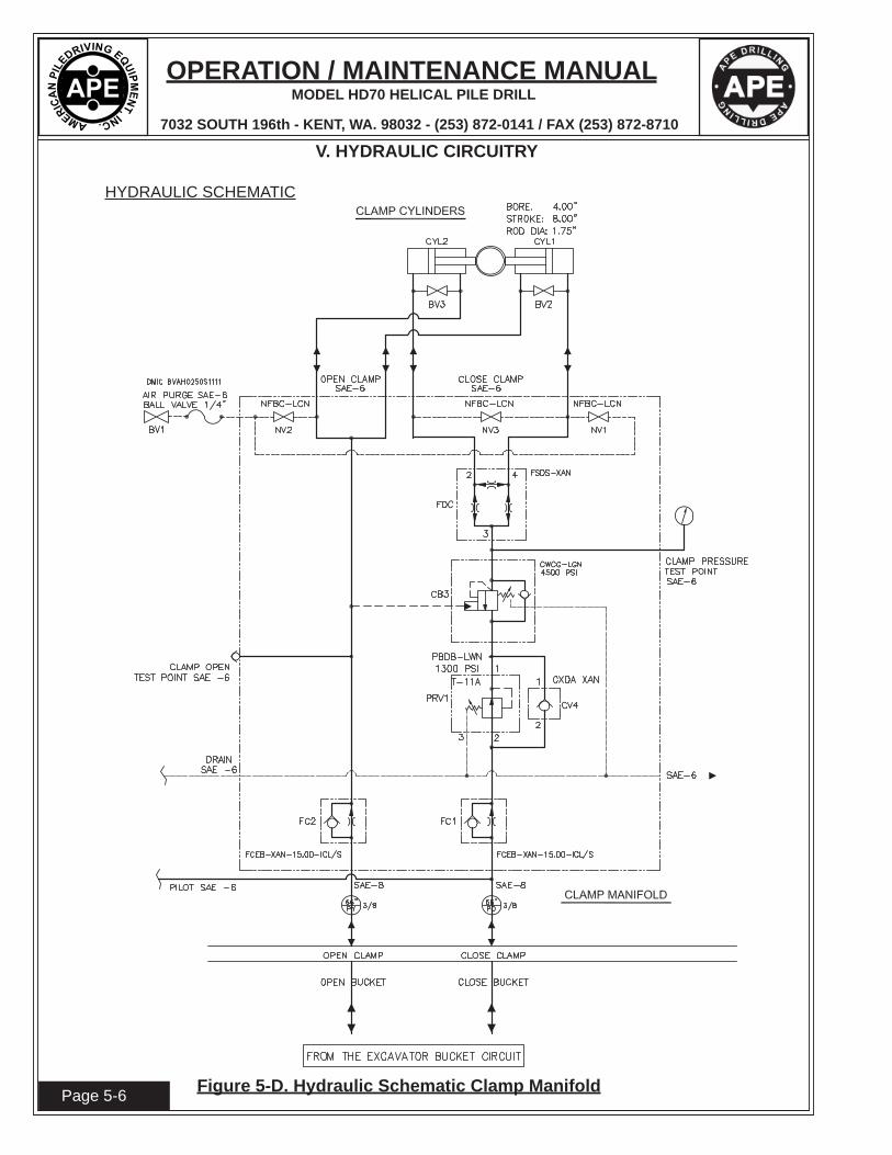
With the excavator engine running, hydraulic fl uid is fed to the bucket circuit. The bucket circuit is connected to the clamp manifold. Pulling the right handle to close the bucket will close the clamp jaws. The clamp pressure can be checked with a gauge installed in the CLAMP PRESSURE TEST POINT port in the clamp manifold. The jaws close together at the same speed due to the fl ow divider / combiner (FDC). The FDC feeds an equal amount of hydraulic fl uid to each clamp cylinder at the same time. The factory sets clamping pressure is set at 2500 psi by the pressure reducing / relieving valve (PRV1). However the clamp pressure is maintained by the counter balance valve (CB3). Pushing the right handle to open the bucket will open the clamp jaws.
V-2. MAIN DRIVE
There are two manifolds to operate the helical pile drill. The "Drill Manifold" connects the excavator to the drill head and the "Interlock Manifold" provides speed control and case fl ushing. With the excavator engine running, hydraulic fl uid is fed to the auxiliary circuit. The auxiliary circuit is connected to the drill manifold. Pushing the toggle on the left hand joystick controls direction control valve (DV5) allows hydraulic fl uid to fl ow through the drill manifold which includes counter balance valve (CB2) into the L port of the drive motor and will spin the drive motor clockwise. Returning the toggle to the center will allow the drive motor to stop with the help of counter balance valve (CB1). Pulling the toggle on the left hand joystick controls the drill direction control valve (DV5) allows hydraulic fl uid to fl ow through the drill manifold which includes CB1 into the R port of the drive motor and will spin the drive motor counter clockwise. Returning the toggle to the center will allow the drive motor to stop with the help of counter balance valve CB2. The forward drive pressure is set at the maximum of 4641 psi by the relief valve (RV3) in Hi Torque. In the same way the reverse drive pressure is set at the maximum of 4641 psi by the relief valve (RV2) in Hi Torque. When the drive motor is spinning pilot fl uid is being directed to the speed lock hot oil shuttle valve (SHV2) and case fl ush hot oil shuttle valve (SHV3). SHV2 directs fl uid to speed pilot check valve (CV5) and speed pilot directional valve (DV2). With these valves getting the pilot fl ow the drive motor speed can not be changed. SHV3 directs fl uid through fl ow control (FC3) allowing a maximum of 1 gpm to fl ow into the drive motor case. Providing fresh fl uid to fl ush during operation aiding in keeping the inside of the drive motor cleaner and cooler. This excess fl ow is removed from the drill motor through the case drain (CD) hose. The case drain fl ow is fi ltered by fi lter (F). During the initial set-up F is to be a 10 micron fi lter element, on subsequent fi lter replacements a 25 micron fi lter can be used. An indicator shows the level of fi lter cleanliness when the hydraulic oil temperature is above 90 degrees F. The pressure of the CD is limited to 50 psi by relief valve (RV4). When CD pressure exceeds 50 psi the hydraulic oil will squirt from RV4.
To change speed the drive motor must NOT be spinning! With the drive motor not spinning turn the knob on the displacement shift valve (DV4) counter clockwise (CCW) until it clicks and locks into place. Hold the clamp close joystick in the close position. The helical pile drill is now in high speed. Pushing the toggle on the left hand joystick controls direction control valve (DV5) allows hydraulic fl uid to fl ow through the drill manifold which includes CB2 into the L port of the drive motor will spin the drive motor clockwise as well as pulling toggle back will cause the motor to spin CCW. RV3 is vented since pilot fl uid has drill manifold directional valve (DV1) shifted which activates relief valve (RV1) and limits the drive pressure to 2700 psi.

OPERATION / MAINTENANCE MANUAL
7032 SOUTH 196th - KENT, WA. 98032 - (253) 872-0141 / FAX (253) 872-8710
MODEL HD70 HELICAL PILE DRILL
Page 5-2 Figure 5-A. Hydraulic Schematic
V. HYDRAULIC CIRCUITRY
HYDRAULIC SCHEMATIC 1000225
OPERATION / MAINTENANCE MANUAL
7032 SOUTH 196th - KENT, WA. 98032 - (253) 872-0141 / FAX (253) 872-8710
MODEL HD70 HELICAL PILE DRILL
Page 5-3
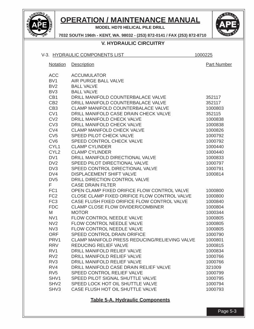
Table 5-A. Hydraulic Components
V. HYDRAULIC CIRCUITRY
V-3. HYDRAULIC COMPONENTS LIST 1000225
Notation Description Part Number
ACC ACCUMULATORBV1 AIR PURGE BALL VALVEBV2 BALL VALVEBV3 BALL VALVECB1 DRILL MANIFOLD COUNTERBALACE VALVE 352117CB2 DRILL MANIFOLD COUNTERBALACE VALVE 352117CB3 CLAMP MANIFOLD COUNTERBALACE VALVE 1000803CV1 DRILL MANIFOLD CASE DRAIN CHECK VALVE 352115CV2 DRILL MANIFOLD CHECK VALVE 1000838CV3 DRILL MANIFOLD CHECK VALVE 1000838CV4 CLAMP MANIFOLD CHECK VALVE 1000826CV5 SPEED PILOT CHECK VALVE 1000792CV6 SPEED CONTROL CHECK VALVE 1000792CYL1 CLAMP CYLINDER 1000440CYL2 CLAMP CYLINDER 1000440DV1 DRILL MANIFOLD DIRECTIONAL VALVE 1000833DV2 SPEED PILOT DIRECTIONAL VALVE 1000797DV3 SPEED CONTROL DIRECTIONAL VALVE 1000791DV4 DISPLACEMENT SHIFT VALVE 1000814DV5 DRILL DIRECTION CONTROL VALVEF CASE DRAIN FILTERFC1 OPEN CLAMP FIXED ORIFICE FLOW CONTROL VALVE 1000800FC2 CLOSE CLAMP FIXED ORIFICE FLOW CONTROL VALVE 1000800FC3 CASE FLUSH FIXED ORIFICE FLOW CONTROL VALVE 1000840FDC CLAMP CLOSE FLOW DIVIDER/COMBINER 1000804M MOTOR 1000344NV1 FLOW CONTROL NEEDLE VALVE 1000805NV2 FLOW CONTROL NEEDLE VALVE 1000805NV3 FLOW CONTROL NEEDLE VALVE 1000805ORF SPEED CONTROL DRAIN ORIFICE 1000790PRV1 CLAMP MANIFOLD PRESS REDUCING/RELIEVING VALVE 1000801RRV REDUCING RELIEF VALVE 1000815RV1 DRILL MANIFOLD RELIEF VALVE 1000834RV2 DRILL MANIFOLD RELIEF VALVE 1000766RV3 DRILL MANIFOLD RELIEF VALVE 1000766RV4 DRILL MANIFOLD CASE DRAIN RELIEF VALVE 321009RV5 SPEED CONTROL RELIEF VALVE 1000799SHV1 SPEED PILOT SIGNAL SHUTTLE VALVE 1000795SHV2 SPEED LOCK HOT OIL SHUTTLE VALVE 1000794SHV3 CASE FLUSH HOT OIL SHUTTLE VALVE 1000793

OPERATION / MAINTENANCE MANUAL
7032 SOUTH 196th - KENT, WA. 98032 - (253) 872-0141 / FAX (253) 872-8710
MODEL HD70 HELICAL PILE DRILL
Page 5-4
V. HYDRAULIC CIRCUITRY
HYDRAULIC SCHEMATIC
Figure 5-B. Hydraulic Schematic Drill Manifold

OPERATION / MAINTENANCE MANUAL
7032 SOUTH 196th - KENT, WA. 98032 - (253) 872-0141 / FAX (253) 872-8710
MODEL HD70 HELICAL PILE DRILL
Page 5-5
V. HYDRAULIC CIRCUITRY
HYDRAULIC SCHEMATIC
Figure 5-C. Hydraulic Schematic Drill Interlock Manifold
OPERATION / MAINTENANCE MANUAL
7032 SOUTH 196th - KENT, WA. 98032 - (253) 872-0141 / FAX (253) 872-8710
MODEL HD70 HELICAL PILE DRILL
Page 5-6
V. HYDRAULIC CIRCUITRY
HYDRAULIC SCHEMATIC
Figure 5-D. Hydraulic Schematic Clamp Manifold

OPERATION / MAINTENANCE MANUAL
7032 SOUTH 196th - KENT, WA. 98032 - (253) 872-0141 / FAX (253) 872-8710
MODEL HD70 HELICAL PILE DRILL
Page 6-1
VI. GENERAL DATA
VI-1. ABBREVIATIONS
The abbreviations shown below are used throughout the parts lists and various other parts of the manual.
ASM. AssemblyBHCS Button Head Cap ScrewCyl. CylinderDC Direct CurrentFHCS Flat Head Cap ScrewFLCS Flanged Head Cap ScrewHC High CollarHHCS Hex Head Cap ScrewHHPP Hex Head Pipe PlugHSSS Hex Socket Set ScrewHyd. HydraulicLg. Longmm MillimeterMtg. MountingNPT. National Pipe ThreadPHMS Phillips Head Machine ScrewP/N Part NumberQty. QuantityRHMS Round Head Machine ScrewSch. ScheduleSHCS Socket Head Cap ScrewSHPP Socket Head Pipe PlugSHSS Socket Head Shoulder ScrewS/N Serial NumberSol. Solenoid
VI-2. SCREW AND BOLTS
1. Practically all connections on the unit are made with socket head (Allen) cap screws. These high-strength screws are available at most industrial supply houses.
2. Screws and bolts are designated in the PARTS LIST in abbreviated form. (Refer to sub-section A, above, for specifi c abbreviations.) Listed below is a typical screw description: 0.50 - 13 UNC X 1.50 LG SHCS
0.50 = Diameter 13 UNC = Threads Per Inch 1.50 LG = Length SHCS = Screw Type Abbreviation
3. Some screws or bolts require a specifi c torque when replacing. For identifi cation of these bolts and a more thorough understanding of torque, refer to Page IV-5.

OPERATION / MAINTENANCE MANUAL
7032 SOUTH 196th - KENT, WA. 98032 - (253) 872-0141 / FAX (253) 872-8710
MODEL HD70 HELICAL PILE DRILL
Page 6-2
VI. GENERAL DATA
VI-3. SERIAL NUMBER LOCATIONS
1. The following Helical Pile Driver units are serial numbered separately:
a. Drill headb. Clamp Bodyc. Socket
2. In addition to the serial number plate itself (on drill head, clamp body and sockets), the se-rial number are welded onto each unit as follows:
a. Drill head welded twice - once on top right side of housing, once on bottom lip of right side of motors’ side.
b. Clamp body stamped twice - once on plate above jaw, once on plate above cylinder cover.
c. Sockets are stamped .

OPERATION / MAINTENANCE MANUAL
7032 SOUTH 196th - KENT, WA. 98032 - (253) 872-0141 / FAX (253) 872-8710
MODEL HD70 HELICAL PILE DRILL
Page 7-1
VII. ORDERING PARTS
VII-1. PROCEDURE
1. When ordering parts, be sure to include the model and serial number of the unit or component. The serial number may be located by referring to SECTION VI, SERIAL NUMBER LOCATION. Confi rm all faxed or e-mailed orders by telephone immediately to avoid duplicating shipment.
2. ORIGINAL EQUIPMENT; Where component serial numbers are given, these apply only to equipment and components originally furnished with the unit. Where equipment has been changed or upgraded these numbers may not be an adequate description.
3. SHIPMENT; State to whom shipment is to be made and method of shipment desired, otherwise our own judgement will be used.
4. SHORTAGES; Claims for shortages or errors should be made immediately upon receipt of parts. No responsibility will be assumed for delay, damage or loss of material while in transit. Broken, damaged or lost material should be refused or a full description made of damage or loss to the carrier agent on the freight or express bill.
5. RETURN OF PARTS; If for any reason you desire to return parts to the factory or to any distributor from whom these parts were obtained, you must fi rst secure permission to return the parts. Shipping instructions will be given along with this permission. A ten percent handling charge must be assessed against the returned shipment unless an error is made by the factory or by the distributor when fi lling your order.

OPERATION / MAINTENANCE MANUAL
7032 SOUTH 196th - KENT, WA. 98032 - (253) 872-0141 / FAX (253) 872-8710
MODEL HD70 HELICAL PILE DRILL
Page 7-2
VII. ORDERING PARTS
VII-2. FITTING DESCRIPTION KEY
Figure 7-A. Fitting Description Key

OPERATION / MAINTENANCE MANUAL
7032 SOUTH 196th - KENT, WA. 98032 - (253) 872-0141 / FAX (253) 872-8710
MODEL HD70 HELICAL PILE DRILL
Page 7-3
Figure 7-B. Fitting Style Selector Chart
VII. ORDERING PARTS
VII-3. FITTING STYLE SELECTOR CHART
For fi tting end style selection.

OPERATION / MAINTENANCE MANUAL
7032 SOUTH 196th - KENT, WA. 98032 - (253) 872-0141 / FAX (253) 872-8710
MODEL HD70 HELICAL PILE DRILL
Page 7-4
Figure 7-C. Hose Description Code
VII. ORDERING PARTS
VII-4. HOSE DESCRIPTION CODE

OPERATION / MAINTENANCE MANUAL
7032 SOUTH 196th - KENT, WA. 98032 - (253) 872-0141 / FAX (253) 872-8710
MODEL HD70 HELICAL PILE DRILL
Page 7-5
VII. ORDERING PARTS
VII-5. PARTS IDENTIFICATION
1. Parts lists and drawings are included on the following pages for the equipment components shown below:
a. HELICAL PILE DRIVER ASSEMBLY 1000443b. DRILL HOUSING ASSEMBLY 1000345c. DRILL MOTOR ASSEMBLY 1000343d. CLAMP HOUSING ASSEMBLY 1000347e. CLAMP CYLINDER ASSEMBLY 1000440f. CLAMP MANIFOLD ASSEMBLY 1000441g. JAW OPTIONS 1000348h. TOP PLATE ASSEMBLY 1000355i. BALE ASSEMBLY 1000356j. PIN ASSEMBLY 1000357k. DRIVE SOCKET OPTIONS 1000358l. SOCKET RETAINER OPTIONS 1000365m. GROUTING ASSEMBLY OPTION 1000346n. GROUT PLUG OPTIONS 1000368o. BLANK PLATE OPTION 1000439p. DRILL MANIFOLD ASM 1000642q. INTERLOCK MANIFOLD ASM 1000375r. ACCUMULATOR ASSEMBLY 1000442s. SAFETY GATE OPTIONS

OPERATION / MAINTENANCE MANUAL
7032 SOUTH 196th - KENT, WA. 98032 - (253) 872-0141 / FAX (253) 872-8710
MODEL HD70 HELICAL PILE DRILL
Page 7-6
VII. ORDERING PARTS
VII-6. HELICAL PILE DRILL IDENTIFICATION 1000443
Figure 7-D. Helical Pile Drill Assembly

OPERATION / MAINTENANCE MANUAL
7032 SOUTH 196th - KENT, WA. 98032 - (253) 872-0141 / FAX (253) 872-8710
MODEL HD70 HELICAL PILE DRILL
Page 7-7
Table 7-A. Helical Pile Drill Assembly
VII. ORDERING PARTS
VII-6. HELICAL PILE DRILL IDENTIFICATION 1000443
PartItem Number Qty. Description
1 1000345 1 DRILL HOUSING ASSEMBLY2 1000343 1 DRILL MOTOR ASSEMBLY3 1000347 1 CLAMP HOUSING ASSEMBLY4 1000440 2 CLAMP CYLINDER ASSEMBLY5 1000441 1 CLAMP MANIFOLD ASSEMBLY6 1000348 2 JAW OPTIONS7 1000355 1 TOP PLATE ASSEMBLY8 1000356 1 BALE ASSEMBLY9 1000357 2 PIN ASSEMBLY10 1000358 2 DRIVE SOCKET OPTIONS11 1000365 1 SOCKET RETAINER OPTIONS12 1000346 1 GROUTING ASSEMBLY OPTION13 1000368 1 GROUT PLUG OPTIONS14 1000439 1 BLANK PLATE OPTION15 523100 1 DRILL MANIFOLD ASM16 1000375 1 INTERLOCK MANIFOLD ASM17 1000442 1 ACCUMULATOR ASSEMBLY
OPERATION / MAINTENANCE MANUAL
7032 SOUTH 196th - KENT, WA. 98032 - (253) 872-0141 / FAX (253) 872-8710
MODEL HD70 HELICAL PILE DRILL
Page 7-8
VII. ORDERING PARTS
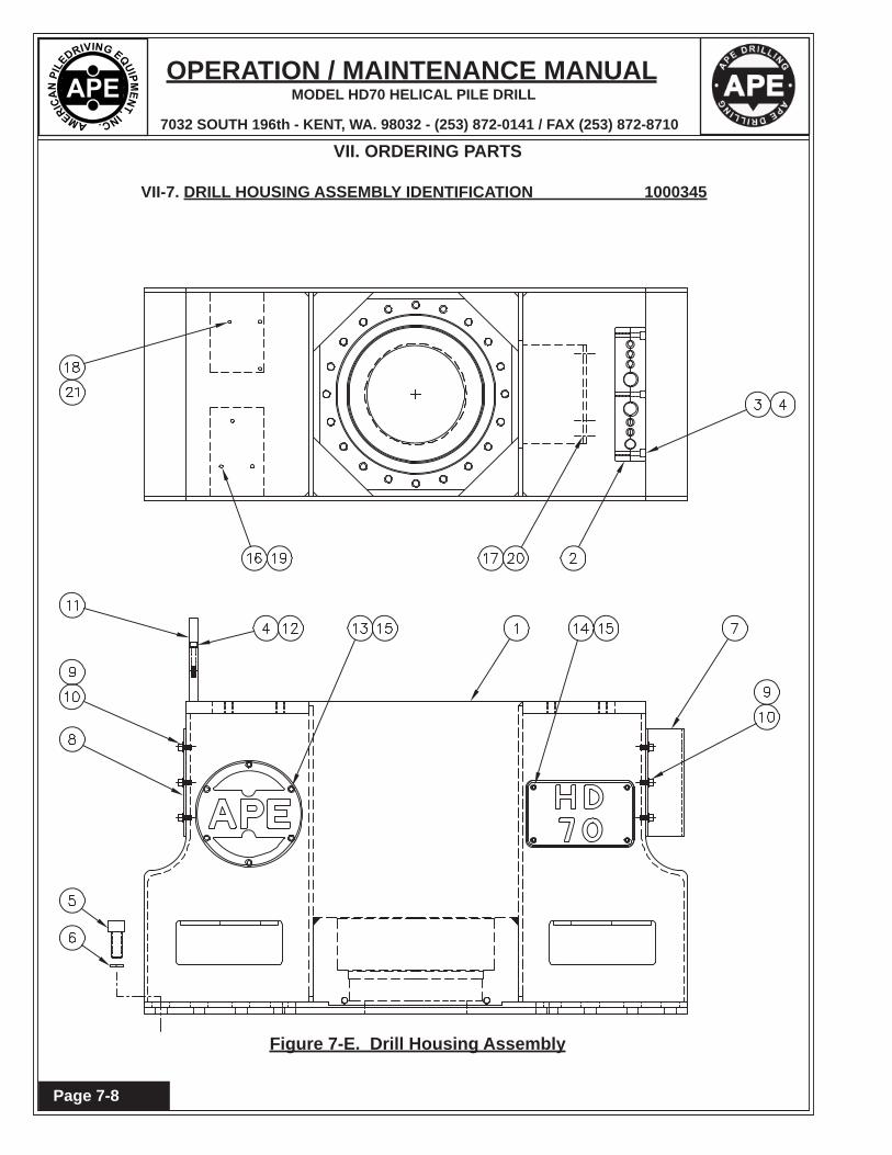
VII-7. DRILL HOUSING ASSEMBLY IDENTIFICATION 1000345
Figure 7-E. Drill Housing Assembly

OPERATION / MAINTENANCE MANUAL
7032 SOUTH 196th - KENT, WA. 98032 - (253) 872-0141 / FAX (253) 872-8710
MODEL HD70 HELICAL PILE DRILL
Page 7-9
VII. ORDERING PARTS
VII-7. DRILL HOUSING ASSEMBLY IDENTIFICATION 1000345
PartItem Number Qty. Description
1 HD-100053 1 Drill Housing - Machined2 HD-100057 1 Hose Block Assembly3 - - - 3 SHCS .50-13 NC x 2.254 - - - 5 HCLW .505 - - - 24 SHCS 1.25-7 NC x 3.006 - - - 24 HCLW 1.257 HD-100059 1 Cover (Drill Manifold End)8 HD-100061 1 Cover (Clamp Manifold End)9 - - - 12 SHCS .50-13 NC x 1.0010 12 Std Washer .5011 HD-100062 1 Yoke Clamp (For Grout Pipe)12 2 SCHS .50-13 NC x 3.5013 HD-100063 2 Custom APE Logo - Finished14 HD-100065 2 HD 70 Logo15 - - - 20 SHCS .44-14 NC X .75 (SS)16 - - - 3 Stover Nut .31-18 NC17 - - - 3 SHCS .50-13 NC x 9.2518 - - - 3 SHCS .38-16 NC X 5.0019 - - - 3 SHCS .31-18 NC X 3.5020 - - - 3 Stover Nut .50-13 NC21 - - - 3 Stover Nut .38-16 NC
Table 7-B. Drill Housing Assembly

OPERATION / MAINTENANCE MANUAL
7032 SOUTH 196th - KENT, WA. 98032 - (253) 872-0141 / FAX (253) 872-8710
MODEL HD70 HELICAL PILE DRILL
Page 7-10
VII. ORDERING PARTS
VII-8. DRILL MOTOR ASSEMBLY IDENTIFICATION 1000343
Figure 7-F. Drill Motor Assembly

OPERATION / MAINTENANCE MANUAL
7032 SOUTH 196th - KENT, WA. 98032 - (253) 872-0141 / FAX (253) 872-8710
MODEL HD70 HELICAL PILE DRILL
Page 7-11
VII. ORDERING PARTS
VII-8. DRILL MOTOR ASSEMBLY IDENTIFICATION 1000343
PartItem Number Qty. Description
1 1000344 1 HD 70 DRILL MOTOR2 5 M20 Lock Washer3 HD-100069 1 Square Drive4 HD-100071 1 Timken Brg LM654649 / LM6546105 - - - 20 SHCS M24-3 X 70mm6 - - - 20 M24 Standard Washer7 - - - 20 M24 HCLW8 1000079 1 Lip Seal9 5 M20-2.5 X 80 mm LG HHCS10 630035 1 O-Ring Auger Sleeve11 630505 1 Auger Shaft Sleeve (Kl. B0698-001 Rev C)12 630518 1 Hyd. Motor End Plate (Kl. B0698-002 Rev B)13 630517 1 Bearing - Top Seal Plate14 630509A 1 O-Ring Top Plate (Kl. B0698-003 Rev C)15 630510 1 Upper Shaft Seal16 HD-100002 1 Oil Seal Carrier17 HD-100001 1 Grout Cover Plate18 1 O-Ring Grout Cover19 100159 1 O-Ring Top Plate20 - - - 2 SHCS 5/16-18 NC x 1.2521 - - - 2 HCLW 5/1622 630516A 1 O-Ring Grout Cover
Table 7-C. Drill Motor Assembly

OPERATION / MAINTENANCE MANUAL
7032 SOUTH 196th - KENT, WA. 98032 - (253) 872-0141 / FAX (253) 872-8710
MODEL HD70 HELICAL PILE DRILL
Page 7-12
VII. ORDERING PARTS
VII-9. CLAMP HOUSING ASSEMBLY IDENTIFICATION 1000347
Figure 7-G. Clamp Housing Assembly

OPERATION / MAINTENANCE MANUAL
7032 SOUTH 196th - KENT, WA. 98032 - (253) 872-0141 / FAX (253) 872-8710
MODEL HD70 HELICAL PILE DRILL
Page 7-13
VII. ORDERING PARTS
VII-9. CLAMP HOUSING ASSEMBLY IDENTIFICATION 1000347
PartItem Number Qty. Description
1 HD-100101 1 Clamp Housing-Machined2 - - - 4 1/8 npt Grease Fitting
Table 7-D. Clamp Housing Assembly

OPERATION / MAINTENANCE MANUAL
7032 SOUTH 196th - KENT, WA. 98032 - (253) 872-0141 / FAX (253) 872-8710
MODEL HD70 HELICAL PILE DRILL
Page 7-14
VII. ORDERING PARTS
VII-10. CLAMP CYLINDER ASSEMBLY IDENTIFICATION 1000440
Figure 7-H. Clamp Cylinder Assembly

OPERATION / MAINTENANCE MANUAL
7032 SOUTH 196th - KENT, WA. 98032 - (253) 872-0141 / FAX (253) 872-8710
MODEL HD70 HELICAL PILE DRILL
Page 7-15
VII. ORDERING PARTS
VII-10. CLAMP CYLINDER ASSEMBLY IDENTIFICATION 1000440
PartItem Number Qty. Description
1 1000470 1 Outer Tube - Machined2 1000532 1 Inner Tube - Final Machine3 1000533 1 Bronze Sleeve4 1000534 1 Purakal Cylinder Asm5 1000535 1 11.500" Rod Wiper6 1000531 4 Pin - Jaw Retainer7 - - - 4 #8 SAE PLUG8 - - - 1 Hex Bolt 1.25-12 NF X 2.509 - - - 1 HCLW 1.2510 - - - 2 #6 SAE X #6 MJIC Fitting11 - - - 1 1/2 NPT Pipe Fitting12 1000536 1 Breather - Schroeder ABF-3/10-M-P1213 - - - 10 SHCS .63-11 NC X 2.0014 - - - 2 2-112 O-Ring15 1000348 1 JAW (SIZED TO PILE) SEE JAW OPTIONS16 1000853 1 HOSE17 1000805 1 NEEDLE VALVE
Table 7-E. Clamp Cylinder Assembly

OPERATION / MAINTENANCE MANUAL
7032 SOUTH 196th - KENT, WA. 98032 - (253) 872-0141 / FAX (253) 872-8710
MODEL HD70 HELICAL PILE DRILL
Page 7-16
VII. ORDERING PARTS
VII-11. CLAMP MANIFOLD ASSEMBLY IDENTIFICATION 1000441
Figure 7-I. Assembly
81
11 4
3
2
9 8 12
13
10
8 78 12
2
46
5
2

OPERATION / MAINTENANCE MANUAL
7032 SOUTH 196th - KENT, WA. 98032 - (253) 872-0141 / FAX (253) 872-8710
MODEL HD70 HELICAL PILE DRILL
Page 7-17
VII. ORDERING PARTS
VII-11. CLAMP MANIFOLD ASSEMBLY IDENTIFICATION 1000441
PartItem Number Qty. Description
1 1 CLAMP MANIFOLD BLOCK2 1000800 2 FLOW CONTROL VALVE3 1000801 1 PRESSURE REDUCING VALVE4 1000826 1 CHECK VALVE5 1000803 1 COUNTERBALANCE VALVE6 1000804 1 FLOW DIVIDE / COMBINER7 1000805 3 NEEDLE VALVE8 1 TEST POINT9 1 GAUGE SNUBBER10 1 PRESSURE GAUGE 0-5000 PSI11 4 #6 O-RING PLUG12 1 #4 O-RING PLUG13 2 #2 O-RING PLUG
Table 7-F. Assembly

OPERATION / MAINTENANCE MANUAL
7032 SOUTH 196th - KENT, WA. 98032 - (253) 872-0141 / FAX (253) 872-8710
MODEL HD70 HELICAL PILE DRILL
Page 7-18
VII. ORDERING PARTS
VII-12. JAW OPTIONS IDENTIFICATION 1000348
Figure 7-J. Jaw Options

OPERATION / MAINTENANCE MANUAL
7032 SOUTH 196th - KENT, WA. 98032 - (253) 872-0141 / FAX (253) 872-8710
MODEL HD70 HELICAL PILE DRILL
Page 7-19
VII. ORDERING PARTS
VII-12. JAW OPTIONS IDENTIFICATION 1000348
PartItem Number Qty. Description
1 1000349 1 Jaw Set for 4-1/2"2 1000350 1 Jaw Set for 5-1/2"3 1000351 1 Jaw Set for 7"4 1000352 1 Jaw Set for 9-5/8"5 1000353 1 Jaw Set for 11-3/4"6 1000354 1 Jaw Set for 13-3/8"
Table 7-G. Jaw Options

OPERATION / MAINTENANCE MANUAL
7032 SOUTH 196th - KENT, WA. 98032 - (253) 872-0141 / FAX (253) 872-8710
MODEL HD70 HELICAL PILE DRILL
Page 7-20
VII. ORDERING PARTS
VII-13. TOP PLATE ASSEMBLY IDENTIFICATION 1000355
Figure 7-K. Top Plate Assembly

OPERATION / MAINTENANCE MANUAL
7032 SOUTH 196th - KENT, WA. 98032 - (253) 872-0141 / FAX (253) 872-8710
MODEL HD70 HELICAL PILE DRILL
Page 7-21
VII. ORDERING PARTS
VII-13. TOP PLATE ASSEMBLY IDENTIFICATION 1000355
PartItem Number Qty. Description
1 HD-100049 1 Lug Plate2 - - - 20 SHCS 1.00-8 NC x 2.253 - - - 20 HCLW 1.00
Table 7-H. Top Plate Assembly

OPERATION / MAINTENANCE MANUAL
7032 SOUTH 196th - KENT, WA. 98032 - (253) 872-0141 / FAX (253) 872-8710
MODEL HD70 HELICAL PILE DRILL
Page 7-22
VII. ORDERING PARTS
VII-14. BALE ASSEMBLY IDENTIFICATION 1000356
Figure 7-L. Bale Assembly

OPERATION / MAINTENANCE MANUAL
7032 SOUTH 196th - KENT, WA. 98032 - (253) 872-0141 / FAX (253) 872-8710
MODEL HD70 HELICAL PILE DRILL
Page 7-23
VII. ORDERING PARTS
VII-14. BALE ASSEMBLY IDENTIFICATION 1000356
PartItem Number Qty. Description
1 HD-100035 1 Bale Assembly - Machined2 HD-100039 2 Hardened Bushing3 HD-100041 1 Standard Excavator Pin4 100229 2 1/8 npt Grease Zerk5 - - - 1 SHCS 3/4-10 NC x 5.506 - - - 1 3/4-10 Stover Nut7 HD-100043 1 Retainer Donut8 HD-100045 2 Connex 4" Dia Spring Bushing x 3.00
Table 7-I. Bale Assembly

OPERATION / MAINTENANCE MANUAL
7032 SOUTH 196th - KENT, WA. 98032 - (253) 872-0141 / FAX (253) 872-8710
MODEL HD70 HELICAL PILE DRILL
Page 7-24
Figure 7-M. Pin Assembly
VII. ORDERING PARTS
VII-15. PIN ASSEMBLY IDENTIFICATION 1000357

OPERATION / MAINTENANCE MANUAL
7032 SOUTH 196th - KENT, WA. 98032 - (253) 872-0141 / FAX (253) 872-8710
MODEL HD70 HELICAL PILE DRILL
Page 7-25
VII. ORDERING PARTS
VII-15. PIN ASSEMBLY IDENTIFICATION 1000357
PartItem Number Qty. Description
1 HD-100047 1 Pin Finished Detail2 100229 1 1/8 NPT Grease Fitting3 - - - 1 Hex Bolt .63-11 NC x 1.754 - - - 1 HCLW .635 - - - 1 SHCS .38-16 NC X 3.756 - - - 1 3/8-16 NC Stover Nut
Table 7-J. Pin Assembly

OPERATION / MAINTENANCE MANUAL
7032 SOUTH 196th - KENT, WA. 98032 - (253) 872-0141 / FAX (253) 872-8710
MODEL HD70 HELICAL PILE DRILL
Page 7-26
Figure 7-N. Drive Socket Options
VII. ORDERING PARTS
VII-16. DRIVE SOCKETOPTIONS IDENTIFICATION 1000358

OPERATION / MAINTENANCE MANUAL
7032 SOUTH 196th - KENT, WA. 98032 - (253) 872-0141 / FAX (253) 872-8710
MODEL HD70 HELICAL PILE DRILL
Page 7-27
VII. ORDERING PARTS
VII-22. DRIVE SOCKETOPTIONS IDENTIFICATION 1000358
PartItem Number Qty. Description
1 1000359 1 Drive Socket for 4-1/2"2 1000360 1 Drive Socket for 5-1/2"3 1000361 1 Drive Socket for 7"4 1000362 1 Drive Socket for 9-5/8"5 1000363 1 Drive Socket for 11-3/4"6 1000364 1 Drive Socket for 13-3/8"
Table 7-K Drive Socket Options

OPERATION / MAINTENANCE MANUAL
7032 SOUTH 196th - KENT, WA. 98032 - (253) 872-0141 / FAX (253) 872-8710
MODEL HD70 HELICAL PILE DRILL
Page 7-28
VII. ORDERING PARTS
VII-17. SOCKET RETAINER IDENTIFICATION 1000365
Figure 7-O. Socket Retainer Options

OPERATION / MAINTENANCE MANUAL
7032 SOUTH 196th - KENT, WA. 98032 - (253) 872-0141 / FAX (253) 872-8710
MODEL HD70 HELICAL PILE DRILL
Page 7-29
VII. ORDERING PARTS
VII-17. SOCKET RETAINER IDENTIFICATION 1000365
PartItem Number Qty. Description
1 1000769 1 Small Socket Retainer Asm.Item P/N Qty Description1 1000366 1 Small Socket Retainer2 12 .88 HCLW3 12 SHCS .88-9 NC X 2.00
2 1000770 1 Large Socket Retainer Asm.Item P/N Qty Description1 1000367 1 Small Socket Retainer2 12 .88 HCLW3 12 SHCS .88-9 NC X 2.00
Table 7-L. Socket Retainer Options

OPERATION / MAINTENANCE MANUAL
7032 SOUTH 196th - KENT, WA. 98032 - (253) 872-0141 / FAX (253) 872-8710
MODEL HD70 HELICAL PILE DRILL
Page 7-30
VII. ORDERING PARTS
VII-18. GROUTING ASSEMBLY IDENTIFICATION 1000346
Figure 7-P. Grouting Assembly

OPERATION / MAINTENANCE MANUAL
7032 SOUTH 196th - KENT, WA. 98032 - (253) 872-0141 / FAX (253) 872-8710
MODEL HD70 HELICAL PILE DRILL
Page 7-31
VII. ORDERING PARTS
VII-18. GROUTING ASSEMBLY IDENTIFICATION 1000346
PartItem Number Qty. Description
1 1000341 3" Grout Swivel Modifi ed2 1000342 1 Cap3 - - - 1 2-159 90 Duro O-Ring4 631057 4 3" Two-Bolt Style Clamp CFB-35 631059 2 3" Sch 80 Elbow-Straight Asm 1112-0926 631058 1 3" Sch 80 Elbow Assembly 1112-0917 - - - 1 2-045 O-Ring 90 Duro for small grout stem8 - - - 2 2-236 O-Ring 90 Duro9 HD-100073 1 Grout Stem (Small)10 HD-100075 1 Grout Stem (Large)11 - - - 1 2-245 O-Ring 90 Duro for large grout stem
Table 7-M. Grouting Assembly

OPERATION / MAINTENANCE MANUAL
7032 SOUTH 196th - KENT, WA. 98032 - (253) 872-0141 / FAX (253) 872-8710
MODEL HD70 HELICAL PILE DRILL
Page 7-32
VII. ORDERING PARTS
VII-19. GROUT PLUG OPTIONS IDENTIFICATION 1000368
Figure 7-Q. Grout Plug Options

OPERATION / MAINTENANCE MANUAL
7032 SOUTH 196th - KENT, WA. 98032 - (253) 872-0141 / FAX (253) 872-8710
MODEL HD70 HELICAL PILE DRILL
Page 7-33
Table 7-N. Grout Plug Options
VII. ORDERING PARTS
VII-19. GROUT PLUG OPTIONS IDENTIFICATION 1000368
PartItem Number Qty. Description
1 1000369 1 Grout Plug Asm for 4-1/2"Item P/N Qty Description1 1 Body2 1 2- O-Ring3 1 Plug4 1 2- O-Ring5 1 Top Cap6 1000767 1 Seal
2 1000370 1 Grout Plug Asm for 5-1/2"Item P/N Qty Description1 1 Body2 1 2- O-Ring3 1 Plug4 1 2- O-Ring5 1 Retainer Ring6 1000767 1 Seal
3 1000371 1 Grout Plug Asm for 7"Item P/N Qty Description1 1 Body2 1 2- O-Ring3 1 Plug4 1 2- O-Ring5 1 Retainer Ring6 1000768 1 Seal

OPERATION / MAINTENANCE MANUAL
7032 SOUTH 196th - KENT, WA. 98032 - (253) 872-0141 / FAX (253) 872-8710
MODEL HD70 HELICAL PILE DRILL
Page 7-34
VII. ORDERING PARTS
VII-20. BLANK PLATE ASSEMBLY IDENTIFICATION 1000439
Figure 7-R. Blank Plate Assembly

OPERATION / MAINTENANCE MANUAL
7032 SOUTH 196th - KENT, WA. 98032 - (253) 872-0141 / FAX (253) 872-8710
MODEL HD70 HELICAL PILE DRILL
Page 7-35
VII. ORDERING PARTS
VII-18. BLANK PLATE ASSEMBLY IDENTIFICATION 1000439
PartItem Number Qty. Description
1 HD-10033 1 Blank Plate (Subs for Clamp Housing)
Table 7-O. Blank Plate Assembly
OPERATION / MAINTENANCE MANUAL
7032 SOUTH 196th - KENT, WA. 98032 - (253) 872-0141 / FAX (253) 872-8710
MODEL HD70 HELICAL PILE DRILL
Page 7-36
VII. ORDERING PARTS
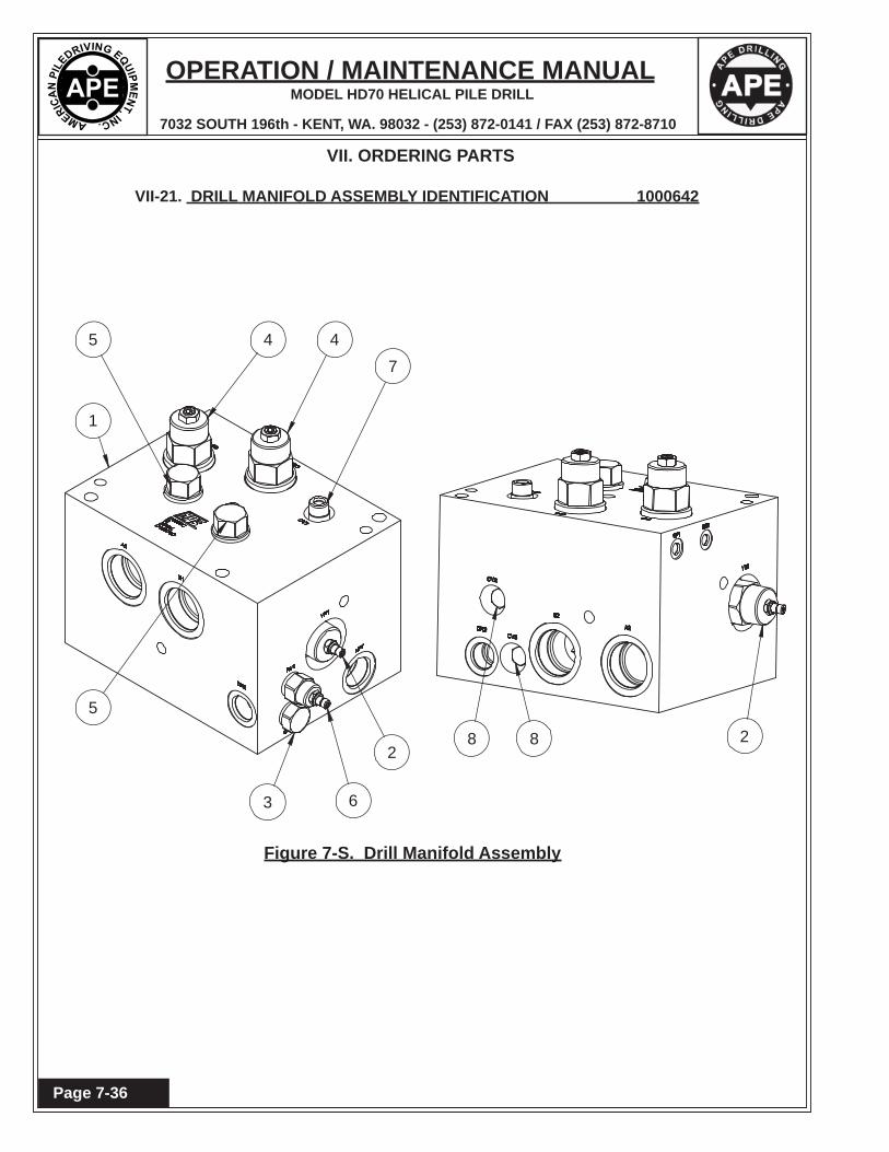
VII-21. DRILL MANIFOLD ASSEMBLY IDENTIFICATION 1000642
Figure 7-S. Drill Manifold Assembly
2
7
1
4 4
5
3 6
5
288

OPERATION / MAINTENANCE MANUAL
7032 SOUTH 196th - KENT, WA. 98032 - (253) 872-0141 / FAX (253) 872-8710
MODEL HD70 HELICAL PILE DRILL
Page 7-37
VII. ORDERING PARTS
VII-21. DRILL MANIFOLD ASSEMBLY IDENTIFICATION 1000642
PartItem Number Qty. Description
1 1 Manifold Block2 1000766 2 RELIEF VALVE3 352115 1 CHECK VALVE4 352117 2 COUNTER BALANCE VALVE5 2 CAVITY PLUG6 1000834 1 RELIEF VAVLE7 1000833 1 DIRECTIONAL VALVE8 1000838 2 CHECK VALVE
Table 7-P. Drill Manifold Assembly

OPERATION / MAINTENANCE MANUAL
7032 SOUTH 196th - KENT, WA. 98032 - (253) 872-0141 / FAX (253) 872-8710
MODEL HD70 HELICAL PILE DRILL
Page 7-38
VII. ORDERING PARTS
VII-22. INTERLOCK MANIFOLD ASSEMBLY IDENTIFICATION 1000375
Figure 7-T. Interlock Manifold Assembly
3
13
2
4
6
11
115
5
12
14 8
87 9
13

OPERATION / MAINTENANCE MANUAL
7032 SOUTH 196th - KENT, WA. 98032 - (253) 872-0141 / FAX (253) 872-8710
MODEL HD70 HELICAL PILE DRILL
Page 7-39
VII. ORDERING PARTS
VII-22. INTERLOCK MANIFOLD ASSEMBLY IDENTIFICATION 1000375
PartItem Number Qty. Description
1 1000791 1 DIRECTIONAL VALVE2 1000840 1 FLOW CONTROL 1 GPM3 400992 1 FITT2P-06R4 110935 14 FITT2P-04R5 1000794 1 SPEED SHUTTLE VALVE6 1000793 1 FLUSH SHUTTLE VALVE7 1000797 1 DIRECTIONAL VALVE8 1000792 2 CHECK VALVE9 1000799 1 RELIEF VALVE10 100646 4 FITT2P-02P11 1000815 1 REDUCING RELIEF VALVE12 1000795 1 SHUTTLE VALVE13 HD-100081 1 MANIFOLD BLOCK14 170822 1 FITT2P-02R15 1000790 1 ORIFICE 0.1 GPM
Table 7-Q. Interlock Manifold Assembly

OPERATION / MAINTENANCE MANUAL
7032 SOUTH 196th - KENT, WA. 98032 - (253) 872-0141 / FAX (253) 872-8710
MODEL HD70 HELICAL PILE DRILL
Page 7-40
VII. ORDERING PARTS
VII-23. ACCUMULATOR ASSEMBLY IDENTIFICATION 1000442
Figure 7-U. Accumulator Assembly
Collar Base (Clamp) (“L” Shaped Bracket)
OPERATION / MAINTENANCE MANUAL
7032 SOUTH 196th - KENT, WA. 98032 - (253) 872-0141 / FAX (253) 872-8710
MODEL HD70 HELICAL PILE DRILL
Page 7-41
VII. ORDERING PARTS
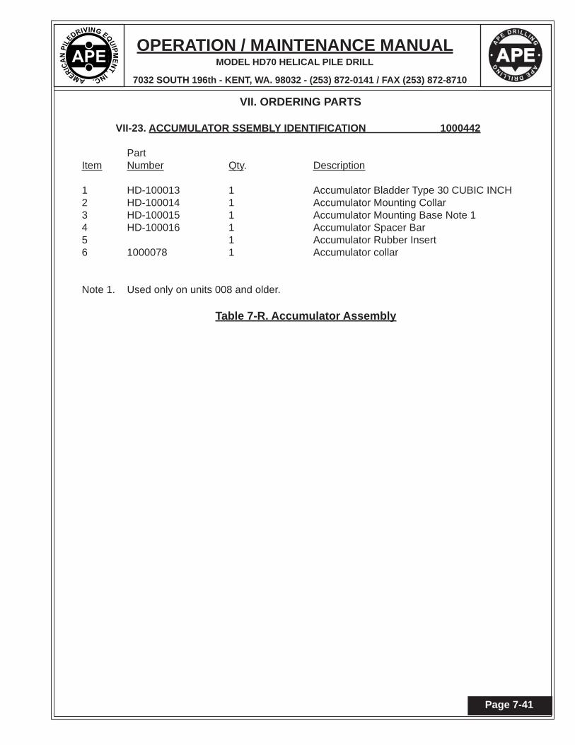
VII-23. ACCUMULATOR SSEMBLY IDENTIFICATION 1000442
PartItem Number Qty. Description
1 HD-100013 1 Accumulator Bladder Type 30 CUBIC INCH2 HD-100014 1 Accumulator Mounting Collar3 HD-100015 1 Accumulator Mounting Base Note 14 HD-100016 1 Accumulator Spacer Bar5 1 Accumulator Rubber Insert6 1000078 1 Accumulator collar
Note 1. Used only on units 008 and older.
Table 7-R. Accumulator Assembly

OPERATION / MAINTENANCE MANUAL
7032 SOUTH 196th - KENT, WA. 98032 - (253) 872-0141 / FAX (253) 872-8710
MODEL HD70 HELICAL PILE DRILL
Page 7-42
VII. ORDERING PARTS
VII-24. SAFETY GATE OPTIONS IDENTIFICATION
Figure 7-V. Safety Gate Options

OPERATION / MAINTENANCE MANUAL
7032 SOUTH 196th - KENT, WA. 98032 - (253) 872-0141 / FAX (253) 872-8710
MODEL HD70 HELICAL PILE DRILL
Page 7-43
VII. ORDERING PARTS
VII-24. SAFETY GATE OPTIONS IDENTIFICATION
PartItem Number Qty. Description
1 1000410 1 4.625" SAFETY GATE ASMITEM P/N QTY Description1 1000417 2 4.625" CUFF 2 1000416 2 SAFETY GATE PIN
2 1000411 1 5.625" SAFETY GATE ASMITEM P/N QTY Description1 1000419 2 5.625" CUFF 2 1000416 2 SAFETY GATE PIN
3 1000412 1 7.125" SAFETY GATE ASMITEM P/N QTY Description1 1000421 2 7.125" CUFF 2 1000416 2 SAFETY GATE PIN
4 1000413 1 9.875" SAFETY GATE ASMITEM P/N QTY Description1 1000423 2 9.875" CUFF 2 1000416 2 SAFETY GATE PIN
5 1000414 1 12" SAFETY GATE ASMITEM P/N QTY Description1 1000425 2 12" CUFF 2 1000416 2 SAFETY GATE PIN
6 1000415 1 13.625" SAFETY GATE ASMITEM P/N QTY Description1 1000427 2 13.625" CUFF 2 1000416 2 SAFETY GATE PIN
Table 7-S. Safety Gate Options

OPERATION / MAINTENANCE MANUAL
7032 SOUTH 196th - KENT, WA. 98032 - (253) 872-0141 / FAX (253) 872-8710
MODEL HD70 HELICAL PILE DRILL
Page 7-44

OPERATION / MAINTENANCE MANUAL
7032 SOUTH 196th - KENT, WA. 98032 - (253) 872-0141 / FAX (253) 872-8710
MODEL HD70 HELICAL PILE DRILL
Page 7-45
VII. ORDERING PARTS
VII-25. RECOMMENDED BOLT TIGHTENING TORQUE
Nominal Nominal Tightening Nominal Nominal TighteningScrew Socket Torque Screw Socket TorqueSize Size Ft-Lbs. (Kg-M) Size Size Ft-Lbs. (Kg-M)
#10-24 5/32 6 Ft-Lbs. (.83 Kg-M) #10-32 5/32 6 Ft-Lbs. (.83 Kg-M)
1/4-20 3/16 13 Ft-Lbs. (1.8 Kg-M) 1/4-28 3/16 15 Ft-Lbs. (2.1 Kg-M)
5/16-18 1/4 27 Ft-Lbs. (3.7 Kg-M) 5/16-24 1/4 30 Ft-Lbs. (4.2 Kg-M)
3/8-16 5/16 48 Ft-Lbs. (6.6 Kg-M) 3/8-24 5/16 55 Ft-Lbs. (7.6 Kg-M)
7/16-14 3/8 77 Ft-Lbs. (10.6 Kg-M) 7/16-20 3/8 86 Ft-Lbs. (11.9 Kg-M)
1/2-13 3/8 119 Ft-Lbs. (16.4 Kg-M) 1/2-20 3/8 133 Ft-Lbs. (18.4 Kg-M)
5/8-11 1/2 234 Ft-Lbs. (32.3 Kg-M) 5/8-18 1/2 267 Ft-Lbs. (36.9 Kg-M)
3/4-10 5/8 417 Ft-Lbs. (57.6 Kg-M) 3/4-16 5/8 467 Ft-Lbs. (64.5 Kg-M)
7/8-9 3/4 676 Ft-Lbs. (93.4 Kg-M) 7/8-14 3/4 742 Ft-Lbs. (102.5 Kg-M)
1-8 3/4 1,009 Ft-Lbs. (139.4 Kg-M) 1-12 3/4 1,126 Ft-Lbs. (155.6 Kg-M)
1-1/4-7 7/8 1,600 Ft-Lbs. (221.1 Kg-M) 1-1/4-12 7/8 1,800 Ft-Lbs. (248.8 Kg-M)
1-1/2-6 1 2,800 Ft-Lbs. (387 Kg-M) 1-1/2-12 1 3,000 Ft-Lbs. (414.6 Kg-M)
NOTE: These values are for Socket head cap screws only. Button heads, Flat heads and Set screws have different values. Check the Allen Hand Book for correct torque specifi cations.

OPERATION / MAINTENANCE MANUAL
7032 SOUTH 196th - KENT, WA. 98032 - (253) 872-0141 / FAX (253) 872-8710
MODEL HD70 HELICAL PILE DRILL
Page 7-46


