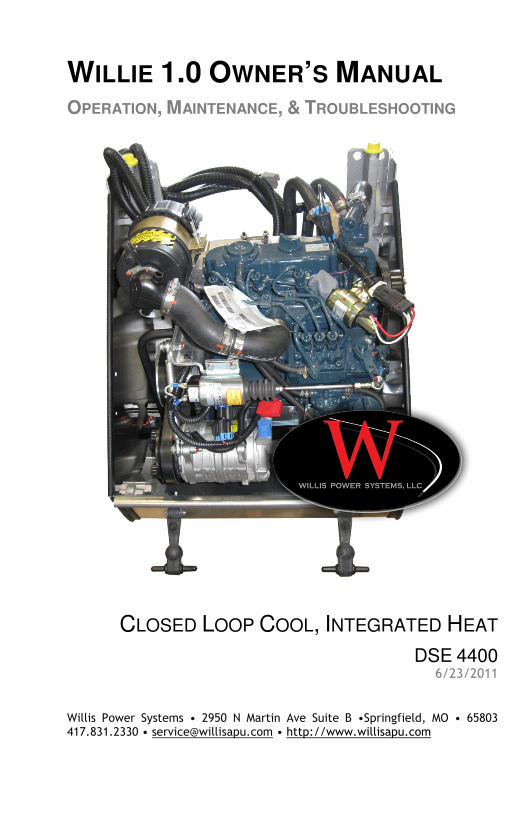
WILLIE 1.0 OWNER’S MANUAL OPERATION, MAINTENANCE, & TROUBLESHOOTING CLOSED LOOP COOL, INTEGRATED HEAT DSE 4400 6/23/2011 Willis Power Systems • 2950 N Martin Ave Suite B •Springfield, MO • 65803 417.831.2330 • [email protected]• http://www.willisapu.com
DC Supply, Fuel, and Start Outputs .................................................... 48
Page 5 of 48
INTRODUCTION TO THE WILLIE 1.0 The Willie APU offers up to 50% more engine power than competitive products and its compact and lightweight design allows for easy installation. Willie™ provides the power and quality while priced competitively to meet the needs of the average driver and trucking company. Willie™ gives built-in redundancy to a big rig’s critical systems.
It is designed to be serviceable and is backed by parts availability. The company provides products that achieve maximum APU-related savings in fuel and maintenance designed to offset the costs of installing emissions control equipment mandated by state idling and federal emissions laws.
PARTS AND SERVICE All parts for the Willis APU are available from the factory and authorized installation centers. Warranty repairs and service must be performed by authorized service centers unless prior authorization has been obtained.
Willis Power Systems http://www.willisapu.com 1-800-825-4631
Have your contact information and engine serial number ready when calling. Please leave a message with the information if the line is busy.
GUIDELINES
• Before operating the Willis APU, be sure and read all manuals included with your purchase to understand the features of the unit.
• Do not remove or replace the APU’s cover while the engine running.
• If the unit is running with the cover off, stay clear of the accessory drive belt.
• The APU contains hot oil and coolant under pressure. Inspect hoses and connections frequently when the engine is NOT running for signs of leakage or damage.
• Do not insert anything in the holes in the transmission case while the APU is running. Do not leave any foreign object in the transmission case.
• Do not work on any Willis APU components located on or near the truck engine when the truck engine is running.
• Only qualified maintenance personnel should operate the Willis APU.
• Refer to Willis Power Systems online to view service locations, or contact WPS by phone for service requests, parts, and additional information.
Page 6 of 48
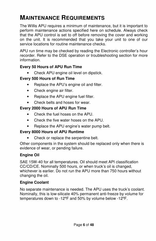
MAINTENANCE REQUIREMENTS The Willis APU requires a minimum of maintenance, but it is important to perform maintenance actions specified here on schedule. Always check that the APU control is set to off before removing the cover and working on the unit. It is recommended that you take your unit to one of our service locations for routine maintenance checks.
APU run time may be checked by reading the Electronic controller’s hour recorder. Refer to the DSE operation or troubleshooting section for more information.
Every 50 Hours of APU Run Time
• Check APU engine oil level on dipstick.
Every 500 Hours of Run Time
• Replace the APU’s engine oil and filter.
• Check engine air filter.
• Replace the APU engine fuel filter.
• Check belts and hoses for wear.
Every 2000 Hours of APU Run Time
• Check the fuel hoses on the APU.
• Check the five water hoses on the APU.
• Replace the APU engine’s water pump belt.
Every 8000 Hours of APU Runtime
• Check or replace the serpentine belt.
Other components in the system should be replaced only when there is evidence of wear, or pending failure.
Engine Oil
SAE 15W-40 for all temperatures. Oil should meet API classification CC/CD/CE. Nominally 500 hours, or when truck’s oil is changed, whichever is earlier. Do not run the APU more than 750 hours without changing the oil.
Engine Coolant
No separate maintenance is needed. The APU uses the truck’s coolant. Nominally, this is low-silicate 40% permanent anti-freeze by volume for temperatures down to -12⁰F and 50% by volume below -12⁰F.
Page 7 of 48
CONTROLLER QUICK START GUIDE You have two main controllers: DSE & Thermostat.
DSE CONTROLS
THERMOSTAT CONTROLS
Page 8 of 48
DSE QUICK START
• Select Stop for the manual mode.
• Then press the Start button to crank the engine.
• Select Stop/Reset to shutdown the APU
THERMOSTAT QUICK START
Page 9 of 48
DSE OPERATING GUIDE The Willis APU Cab Controller is mounted on the truck’s instrument panel. The Cab Controller’s menu screen shows all selected actions.
When the APU has power, it will display a menu saying “Select Mode” or “Shutdown.”
When the Controller is not in use it will cycle between being blank and being on at half brightness. This is normal.
The sequence of screens (pressing the “Up” arrow) is 1) Select Mode, Shutdown 2) Manual 3) Auto 4) Monitor 5) Utility, back to Select Mode Shutdown.
There are five modes to select from: Shutdown, Manual, Auto, Monitor, and Utility.
MANUAL This is the APU “Start” position when the truck has not been running long enough for the APU engine to be warm. This mode starts and operates the APU whether the truck engine is running or not. In the case where the Truck has not been running and is cold, the APU must be started in “Manual” mode in order activate the APU engine’s glow plugs. Upon switching to “Manual” there will be a 90-second delay while the glow plugs heat before the APU engine begins to crank. Once the engine is running the glow plugs will shut off automatically. Once the APU engine is running, it can be switched to “Auto” mode; this is the normal procedure. The air conditioner and heater will operate (if the A/C or heater is “On” in the cab). To operate the APU engine at low RPM when air pressure is not needed, one might choose to operate the APU in Manual. Noise will be minimized since the APU will not cycle between low RPM and high RPM. The truck’s heater can be turned on and will operate normally truck’s “Start” switch is in the “Accessory” or “On” position.
• Select Stop for the manual mode.
• Then press the Start button to crank the engine.
• Select Stop/Reset to shutdown the APU
Nothing more is required to operate the APU.
Page 10 of 48
AUTO
This mode starts the APU when the truck engine has been operating and the driver stops and sets the truck’s parking brake. The truck engine will shut down if it has been programmed to do so.
Turn the “Start” key to the “On” position if air conditioner or heater operation is desired. The APU shuts down automatically when the truck engine is restarted and the parking brake is released (once the air pressure is at an acceptable level in the truck’s air tank). The A/C compressor will operate as needed in this mode.
Activate auto mode by pressing the pushbutton. The icon is displayed to indicate Auto Mode operations if no alarms are present.
MONITOR “Monitor” mode is used when the truck is to be inactive for one to several days. In this mode the APU is started automatically when battery voltage is low or engine temperature drops below 55oF. Once the APU is started, it runs until voltage and engine temperature reach acceptable levels, and then it shuts down again automatically. Leave the truck “Start” key in the “Off” position, and shutdown the APU when in “Monitor” mode. Note that the APU may start at any time when in this mode.
UTILITY This mode allows the operator to set the clock, check and change the service hours, change the display, set the APU idle, and activate the timed run.
ENGINE SERVICE Engine Service keeps track of APU engine run time and it also enables the operator to set a service-hour threshold. Scroll and select “Eng Service.” You will see “Engine Hours” displayed. Press the display button to see “Service Hours.”
BACK LIGHT
The backlight will be on if the unit has sufficient voltage on the power connection while the unit is turned on, unless the unit is cranking for which the backlight will be turned off.
Page 11 of 48
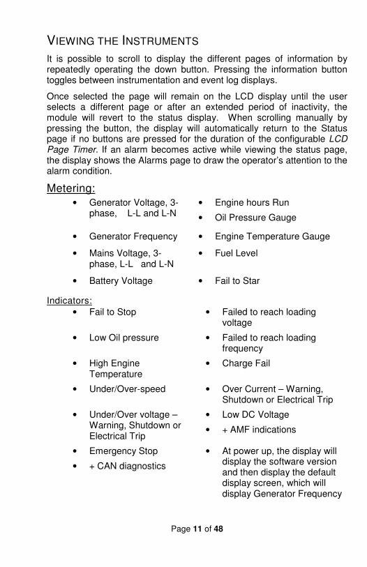
VIEWING THE INSTRUMENTS
It is possible to scroll to display the different pages of information by repeatedly operating the down button. Pressing the information button toggles between instrumentation and event log displays.
Once selected the page will remain on the LCD display until the user selects a different page or after an extended period of inactivity, the module will revert to the status display. When scrolling manually by pressing the button, the display will automatically return to the Status page if no buttons are pressed for the duration of the configurable LCD Page Timer. If an alarm becomes active while viewing the status page, the display shows the Alarms page to draw the operator’s attention to the alarm condition.
Metering:
• Generator Voltage, 3-phase, L-L and L-N
• Engine hours Run
• Oil Pressure Gauge
• Generator Frequency • Engine Temperature Gauge
• Mains Voltage, 3-phase, L-L and L-N
• Fuel Level
• Battery Voltage • Fail to Star
Indicators:
• Fail to Stop • Failed to reach loading voltage
• Low Oil pressure • Failed to reach loading frequency
• High Engine Temperature
• Charge Fail
• Under/Over-speed • Over Current – Warning, Shutdown or Electrical Trip
• Under/Over voltage – Warning, Shutdown or Electrical Trip
• Low DC Voltage
• + AMF indications
• Emergency Stop
• + CAN diagnostics
• At power up, the display will display the software version and then display the default display screen, which will display Generator Frequency
Page 12 of 48
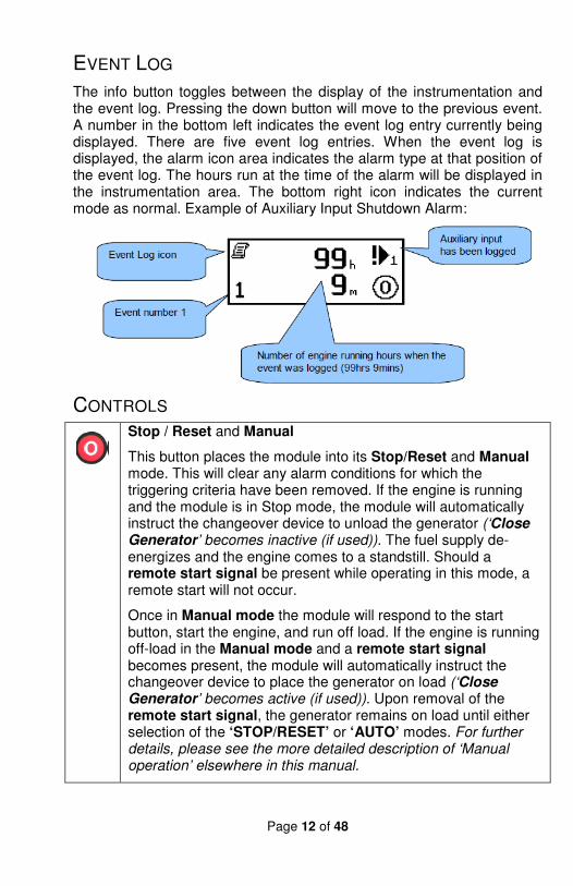
EVENT LOG
The info button toggles between the display of the instrumentation and the event log. Pressing the down button will move to the previous event. A number in the bottom left indicates the event log entry currently being displayed. There are five event log entries. When the event log is displayed, the alarm icon area indicates the alarm type at that position of the event log. The hours run at the time of the alarm will be displayed in the instrumentation area. The bottom right icon indicates the current mode as normal. Example of Auxiliary Input Shutdown Alarm:
CONTROLS
Stop / Reset and Manual
This button places the module into its Stop/Reset and Manual mode. This will clear any alarm conditions for which the triggering criteria have been removed. If the engine is running and the module is in Stop mode, the module will automatically instruct the changeover device to unload the generator (‘Close
Generator’ becomes inactive (if used)). The fuel supply de-energizes and the engine comes to a standstill. Should a remote start signal be present while operating in this mode, a remote start will not occur.
Once in Manual mode the module will respond to the start button, start the engine, and run off load. If the engine is running off-load in the Manual mode and a remote start signal becomes present, the module will automatically instruct the changeover device to place the generator on load (‘Close
Generator’ becomes active (if used)). Upon removal of the remote start signal, the generator remains on load until either selection of the ‘STOP/RESET’ or ‘AUTO’ modes. For further details, please see the more detailed description of ‘Manual operation’ elsewhere in this manual.
Page 13 of 48
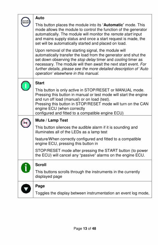
Auto
This button places the module into its ‘Automatic’ mode. This mode allows the module to control the function of the generator automatically. The module will monitor the remote start input and mains supply status and once a start request is made, the set will be automatically started and placed on load.
Upon removal of the starting signal, the module will automatically transfer the load from the generator and shut the set down observing the stop delay timer and cooling timer as necessary. The module will then await the next start event. For further details, please see the more detailed description of ‘Auto operation’ elsewhere in this manual.
Start
This button is only active in STOP/RESET or MANUAL mode. Pressing this button in manual or test mode will start the engine and run off load (manual) or on load (test). Pressing this button in STOP/RESET mode will turn on the CAN engine ECU (when correctly configured and fitted to a compatible engine ECU)
Mute / Lamp Test
This button silences the audible alarm if it is sounding and illuminates all of the LEDs as a lamp test
feature/When correctly configured and fitted to a compatible engine ECU, pressing this button in
STOP/RESET mode after pressing the START button (to power the ECU) will cancel any “passive” alarms on the engine ECU.
Scroll
This buttons scrolls through the instruments in the currently displayed page
Page
Toggles the display between instrumentation an event log mode,
Page 14 of 48
AUTOMATIC MODE OF OPERATION NOTE: IF A DIGITAL INPUT CONFIGURED TO PANEL LOCK IS ACTIVE, CHANGING MODULE MODES WILL NOT BE POSSIBLE. VIEWING THE INSTRUMENTS
AND EVENT LOGS IS NOT AFFECTED BY PANEL LOCK.
Activate auto mode by pressing the pushbutton. The icon is displayed to indicate Auto Mode operations if no alarms are present. Auto mode will allow the generator to operate fully automatically, starting and stopping as required with no use intervention.
WAITING IN AUTO MODE If a starting request is made, the starting sequence will begin.
Starting requests can be from the following sources:
• Mains failure (DSE4420 only)
• Activation of an auxiliary input that has been configured to remote start
• Activation of the inbuilt exercise scheduler
STARTING SEQUENCE
To allow for ‘false’ start requests, the start delay timer begins. Should all start requests be removed during the start delay timer, the unit will return to a stand-by state. If a start request is still present at the end of the start delay timer, the fuel relay is energized and the engine will be cranked.
NOTE: IF THE UNIT HAS BEEN CONFIGURED FOR CAN, COMPATIBLE ECU’S WILL RECEIVE THE START COMMAND VIA CAN.
If the engine fails to fire during this cranking attempt then the starter motor is disengaged for the crank rest duration after which the next start attempt is made. Should this sequence continue beyond the set number of attempts, the start sequence will be terminated and the display shows Fail to Start when the engine fires, the starter motor is disengaged. Speed detection is factory configured to be derived from the main alternator output frequency but can additionally be measured from a Magnetic Pickup mounted on the flywheel (Selected by PC using the 3000 series configuration software). Additionally, rising oil pressure can be used to disconnect the starter motor (but cannot detect underspeed or overspeed).
NOTE: IF THE UNIT HAS BEEN CONFIGURED FOR CAN, SPEED SENSING IS VIA CAN.
Page 15 of 48
After the starter motor has disengaged, the Safety On timer activates, allowing Oil Pressure, High Engine Temperature, Under-speed, Charge Fail and any delayed Auxiliary fault inputs to stabilize without triggering the fault.
ENGINE RUNNING
Once the engine is running and all starting timers have expired, the animated icon is displayed. DSE4410 - The generator will be placed on load if configured to do so.
NOTE: THE LOAD TRANSFER SIGNAL REMAINS INACTIVE UNTIL THE OIL PRESSURE HAS RISEN; THIS PREVENTS EXCESSIVE WEAR ON THE ENGINE.
If all start requests are removed, the stopping sequence will begin.
STOPPING SEQUENCE
The return delay timer operates to ensure that the starting request has been permanently removed and isn’t just a short term removal. Should another start request be made during the cooling down period, the set will return on load. If there are no starting requests at the end of the return delay timer, the load is removed from the generator to the mains supply and the cooling timer is initiated. The cooling timer allows the set to run off load and cool sufficiently before being stopped. This is particularly important where turbo chargers are fitted to the engine.
After the cooling timer has expired, the set is stopped.
MODULE DISPLAY
Backlight
The backlight will be on if the unit has sufficient voltage on the power connection while the unit is turned on, unless the unit is cranking for which the backlight will be turned off.
Graphical Display
A 48x132 pixel LCD is used for the display. The display is segmented into areas for instrumentation, units, alarm icons and various other icons.
Display Example
Page 16 of 48
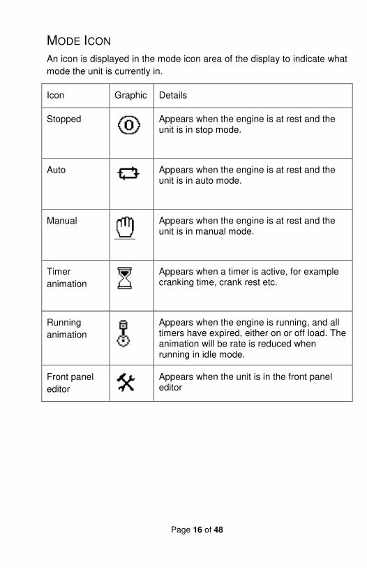
MODE ICON
An icon is displayed in the mode icon area of the display to indicate what
mode the unit is currently in.
Icon Graphic Details
Stopped
Appears when the engine is at rest and the unit is in stop mode.
Auto
Appears when the engine is at rest and the unit is in auto mode.
Manual
Appears when the engine is at rest and the unit is in manual mode.
Timer
animation
Appears when a timer is active, for example cranking time, crank rest etc.
Running
animation
Appears when the engine is running, and all timers have expired, either on or off load. The animation will be rate is reduced when running in idle mode.
Front panel
editor
Appears when the unit is in the front panel editor
Page 17 of 48
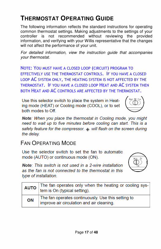
THERMOSTAT OPERATING GUIDE The following information reflects the standard instructions for operating common thermostat settings. Making adjustments to the settings of your controller is not recommended without reviewing the provided information, and verifying with your Willis representative that the changes will not affect the performance of your unit.
For detailed information, view the instruction guide that accompanies your thermostat.
NOTE: YOU MUST HAVE A CLOSED LOOP (CIRCUIT) PROGRAM TO EFFECTIVELY USE THE THERMOSTAT CONTROLS. IF YOU HAVE A CLOSED LOOP AC SYSTEM ONLY, THE HEATING SYSTEM IS NOT AFFECTED BY THE THERMOSTAT. IF YOU HAVE A CLOSED LOOP HEAT AND AC SYSTEM THEN BOTH HEAT AND AC CONTROLS ARE AFFECTED BY THE THERMOSTAT.
FAN OPERATING MODE
Page 18 of 48
DISPLAYING THE TEMPERATURE
SETTING THE TEMPERATURE
BACKLIGHT
THERMOSTAT CONTROL MODE
Manual/Permanent Hold Mode
Programmable Mode
Temporary Bypass
Page 19 of 48
BATTERY REPLACEMENT INDICATOR
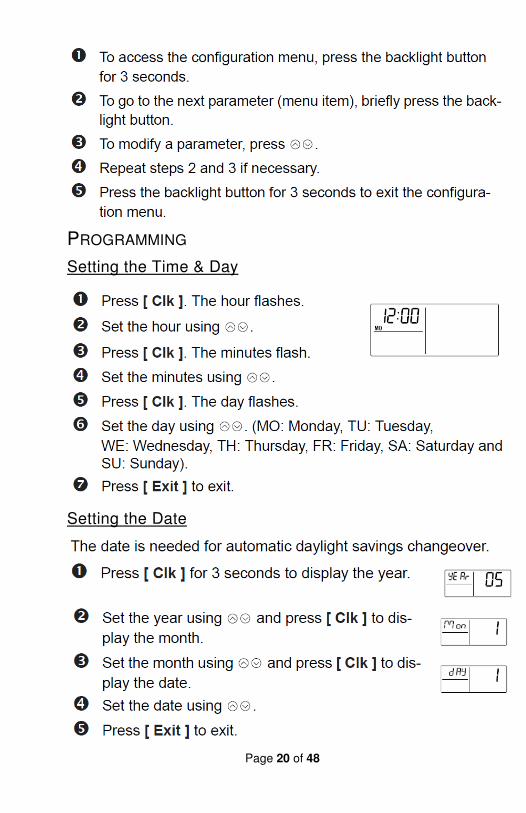
CONFIGURATION MENU
Page 20 of 48
PROGRAMMING
Setting the Time & Day
Setting the Date
Page 21 of 48
ENERGY SAVING SCHEDULE
Modifying Your Schedule
Page 22 of 48
Page 23 of 48
APU TROUBLESHOOTING GUIDE
FAILURE TO START
If there is no response at all to setting the Electronic Controller to “Manual” operating position, there may a problem with the Electronic Controller, the connection between the Controller and the ECM is open, the truck battery is dead, or if equipped, the battery “SWITCH” may be ‘OFF’.
The APU engine may fail to start if:
a) It lacks fuel; a fuel shortage may be due to air in the fuel line or a blocked fuel filter.
b) There is a problem with the electronic controller,
c) The battery or starter has a problem,
d) It lacks intake air; too little intake air may be from a restriction in the air supply system.
e) The starter control relay is bad,
f) There is blockage in the exhaust system
g) The engine speed sensor is defective.
ENGINE WILL NOT GO TO HIGH RPM
Engine output may be low if a) the throttle-advance solenoid is not working, b) the throttle linkage has a problem, or c) the Electronic Controller isn’t sending proper output.
APU ENGINE STOPS SUDDENLY
Sudden stopping may be due to a) the Electronic Controller senses overheating or low oil pressure (warning light comes on), b) fuel pump failure, c) “shutdown solenoid” relay failure, d) fuel shutoff solenoid failure, e) engine speed sensor failure, or f) the truck’s fuel tank is empty.
APU ENGINE OVERHEATS
If the engine overheats it will shut down (warning light will come on). Look for a coolant hose leak or blockage, or water pump or water pump belt failure. Check coolant level in the main engine. Check to make sure the coolant control valve at the truck radiator is open.
Page 24 of 48
OIL LEAKS
Oil accumulating in the bottom of the enclosure case is not normal.
Check hoses from the oil pump to truck engine.
Make sure the breather hose (if so equipped) extends through bottom of case.
SERPENTINE DRIVE BELT FAILURE
Failure of the APU’s internal drive belt causes all accessories, except the oil pump, to stop functioning.
There will be no alternator function, no A/C compressor, and no pneumatic compressor.
Failure symptom: the unit will not go to “low idle” and there will be a slight increase in APU engine RPM over the normal “high idle” RPM.
ALTERNATOR FAILURE
The battery will discharge when the APU is running. The APU may experience an overly high temperature reading in the enclosure as the alternator approaches failure.
PNEUMATIC COMPRESSOR FAILURE
The truck’s air tank won’t pressurize when running the APU.
ENGINE SPEED SENSOR FAILURE
If the speed sensor fails the APU will start about 5 seconds, and attempt to run the self test. Without a speed signal the test will fail and the APU will shutdown. No fault will be recorded on the dash control.
AIR CONDITION COMPRESSOR FAILURE
If there is no air conditioning when running the APU it may be due to
• A/C compressor failure
• Refrigerant leak
• Failure of the A/C pressure switch
• Failures of the fan drive system on the truck.
If the fan drive motor on the truck isn’t working the APU’s Air Conditioner compressor will cycle on and off every few seconds. Do not operate the air conditioner if this is happening.
TRUCK INTERFACE PROBLEMS
Page 25 of 48
Fan Drive System
Failure of the fan drive system may be due to DC drive motor failure, clutch failure, belt failure, timer failure, or failure of the fan solenoid. As noted above, the APU’s air conditioner compressor will cycle in short intervals if the fan is not being driven. Do not operate the air conditioner if this is happening.
Air Governor
Air pressure will either be too high or too low.
Air Intake System to APU
The APU won’t run if the air intake hose becomes blocked.
Exhaust System
The APU won’t start if too much restriction of the exhaust system occurs.
Symptom Check #1
Additional Checks
Probable Cause
Actions
APU does not start
Display does not have power
Check fuses and mega fuse block
Fuse / Relay link broken
Replace fuse and relay if necessary. Look for loose connections or corrosion in wire
Verify correct voltage at (+) post on APU
Bad battery or loose connection
12 volts minimum required
Are connections clean
Road dirt / tar Clean connections
Check supply power at ECU
This is pin(2) at the 12 pin male connector
System voltage
If voltage checks OK
Bad ECU Replace ECU
Before installing new ECU
Verify new ECU has new battery
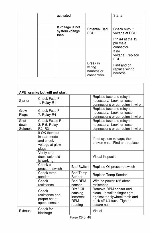
Display has power
Check F1 fuse and R1 relay (Power at Starter)
Fuse / Relay link broken
Replace fuse and relay if necessary. Look for loose connections or corrosion in wire
If OK, check voltage at starter wire when
Potential Bad Starter
If voltage is system voltage then replace
Page 26 of 48
activated Starter
If voltage is not system voltage then
Potential Bad ECU
Check output voltage at ECU
Pin #4 at the 12 pin male connector
If no voltage…replace ECU
Break in wiring harness or connection
Find and or replace wiring harness
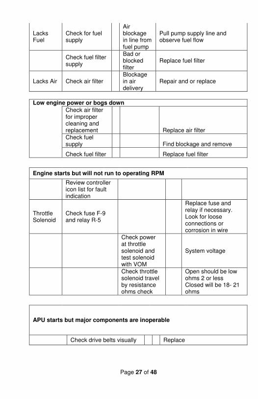
APU cranks but will not start
Starter Check Fuse F-1, Relay R1
Replace fuse and relay if necessary. Look for loose connections or corrosion in wire
Glow Plugs
Check Fuse F-7, Relay R4
Replace fuse and relay if necessary. Look for loose connections or corrosion in wire
Shut down Solenoid
Check Fuses F-3, F-5, Relay R2, R3
Replace fuse and relay if necessary. Look for loose connections or corrosion in wire
If OK then put in start mode and check voltage at glow plugs
If not system voltage; then broken wire. Find and replace
Verify shut down solenoid is working
Visual inspection
Check oil pressure switch
Bad Switch Replace Oil pressure switch
Check temp sender
Bad Temp Sender
Replace Temp Sender
Check resistance
Bad RPM sensor
With no power 135 ohms resistance
Check resistance and proper set of speed sensor
Dirt / Oil causing incorrect RPM reading
Remove RPM sensor and clean. Install to finger tight against the flywheel teeth and back off 1/4 turn. Tighten secure nut.
Exhaust Check for blockage
Visual
Page 27 of 48
Lacks Fuel
Check for fuel supply
Air blockage in line from fuel pump
Pull pump supply line and observe fuel flow
Check fuel filter supply
Bad or blocked filter
Replace fuel filter
Lacks Air Check air filter Blockage in air delivery
Repair and or replace
Low engine power or bogs down
Check air filter for improper cleaning and replacement Replace air filter
Check fuel supply Find blockage and remove
Check fuel filter Replace fuel filter
Engine starts but will not run to operating RPM
Review controller icon list for fault indication
Throttle Solenoid
Check fuse F-9 and relay R-5
Replace fuse and relay if necessary. Look for loose connections or corrosion in wire
Check power at throttle solenoid and test solenoid with VOM
System voltage
Check throttle solenoid travel by resistance ohms check
Open should be low ohms 2 or less Closed will be 18- 21 ohms
APU starts but major components are inoperable
Check drive belts visually Replace
Page 28 of 48
AC inoperable
Check in-line fuses
Replace fuse and relay if necessary. Look for loose connections or corrosion in wire
Check belt on AC compressor
Replace
Check power at AC clutch connection
System voltage
Check R134 level Add additional if necessary
Check for evidence of R134 leakage at all AC fittings…this is the most common cause of AC failure
Yellowish color at fitting crimp or threads
APU will not go to high idle
Throttle Solenoid
Check fuse F-9 and relay R-5
Replace fuse and relay if necessary. Look for loose connections or corrosion in wire
Check power at throttle solenoid and test solenoid with VOM
System voltage
Check throttle solenoid travel by resistance ohms check
Open should be low ohms 2 or less Closed will be 18- 21 ohms
WPS "Willie" APU
In Cab A/C switch connection
Fix connection or replace switch
APU alternator not charging
Check drive belt
Broken belt Replace alternator belt
Check alternator output to system voltage 14 volts+
Bad Alternator
Replace alternator
Page 29 of 48
APU A/C compressor not working
Check drive belt
Broken belt Replace belt
Check for system voltage at clutch wire
A/C clutch Replace A/C compressor and clutch
Check for freon leakage
Road vibration causing leak at fitting or hoses
Replace fittings / hoses and pull vacuum to verify proper seal.
APU A/C on not cooling
A/C charge
Check for leaks
Road vibration causing leak at fitting or hoses
Replace fittings / hoses and pull vacuum to verify proper seal.
A/C fan inoperable
Check in-line fuse / breaker and relay
Loose connections
Replace fuse and relay if necessary. Look for loose connections or corrosion in wire
A/C high pressure switch
Check for power going through if over 300psi
Replace if no system voltage
Oil pressure switch
Check for power going through if truck engine off
Replace if no system voltage
Solenoid
Check that solenoid is switching
Replace if not switching
Page 30 of 48
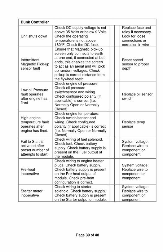
Bunk Controller
Unit shuts down
Check DC supply voltage is not above 35 Volts or below 9 Volts Check the operating temperature is not above 160°F. Check the DC fuse.
Replace fuse and relay if necessary. Look for loose connections or corrosion in wire
Intermittent Magnetic Pick-up sensor fault
Ensure that Magnetic pick-up screen only connects to earth at one end, if connected at both ends, this enables the screen to act as an aerial and will pick up random voltages. Check pickup is correct distance from the flywheel teeth.
Reset speed sensor to proper depth
Low oil Pressure fault operates after engine has fired
Check engine oil pressure. Check oil pressure switch/sensor and wiring. Check configured polarity (if applicable) is correct (i.e. Normally Open or Normally Closed)
Replace oil sensor switch
High engine temperature fault operates after engine has fired.
Check engine temperature. Check switch/sensor and wiring. Check configured polarity (if applicable) is correct (i.e. Normally Open or Normally Closed)
Replace temp sensor
Fail to Start is activated after preset number of attempts to start
Check wiring of fuel solenoid. Check fuel. Check battery supply. Check battery supply is present on the Fuel output of the module.
System voltage: Replace wire to component or component
Pre-heat inoperative
Check wiring to engine heater plugs. Check battery supply. Check battery supply is present on the Pre-heat output of module. Check pre-heat configuration is correct.
System voltage: Replace wire to component or component
Starter motor inoperative
Check wiring to starter solenoid. Check battery supply. Check battery supply is present on the Starter output of module.
System voltage: Replace wire to component or component
Page 31 of 48
DSE TROUBLESHOOTING GUIDE
INSTRUMENTATION ICONS
When displaying instrumentation a small icon is displayed in the instrumentation icon area to indicate what value is currently being displayed. This is necessary to distinguish between mains and generator voltages, icons for oil pressure and coolant temperature are added for consistency.
Icon Graphic Details
Generator
Used for generator voltage and generator frequency
Mains
Used for mains voltages and mains frequency
Engine Speed
Engine speed instrumentation screen
Hours Run
Hours run instrumentation screen
Battery Voltage
Battery voltage instrumentation screen
Engine Temp
Coolant temperature instrumentation screen
Oil Pressure
Oil pressure instrumentation screen
Flexible Sensor
Flexible sensor instrumentation screen
Event Log
Appears when the event log is being displayed.
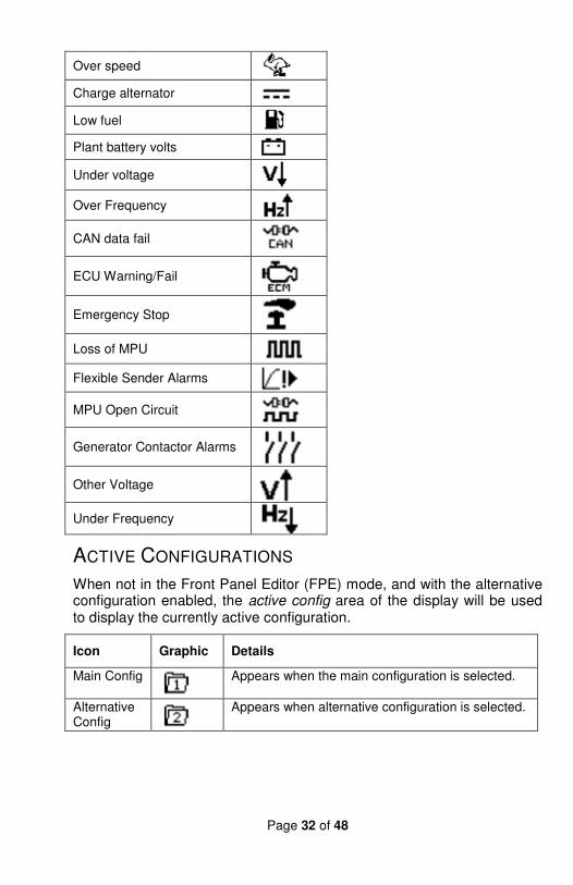
ALARM ICONS
When current instrumentation is being displayed the icons area will be used to display currently active conditions. In instances where more than one alarm is present the icon area will transition between icons to display all active alarm conditions. When the event log is being displayed the alarm icon area will be used to indicate which alarm was logged.
Alarms Icon
External input alarm
Failed to start
Failed to stop
Low oil pressure
Water temperature
Under speed
Page 32 of 48
Over speed
Charge alternator
Low fuel
Plant battery volts
Under voltage
Over Frequency
CAN data fail
ECU Warning/Fail
Emergency Stop
Loss of MPU
Flexible Sender Alarms
MPU Open Circuit
Generator Contactor Alarms
Other Voltage
Under Frequency
ACTIVE CONFIGURATIONS
When not in the Front Panel Editor (FPE) mode, and with the alternative configuration enabled, the active config area of the display will be used to display the currently active configuration.
Icon Graphic Details
Main Config
Appears when the main configuration is selected.
Alternative Config
Appears when alternative configuration is selected.
Page 33 of 48
PROTECTIONS
When an alarm is present, the Common alarm LED will illuminate.
The LCD display will jump from the ‘Information page’ to display the Alarm Page. See section entitled Graphical
Display for details of alarm icons.
The LCD will display multiple alarms E.g. “High Engine Temperature shutdown”, “Emergency Stop” and “Low Coolant Warning”. These will automatically scroll round in the order that they occurred;
In the event of a warning alarm, the LCD will display the appropriate icon. If a shutdown then occurs, the module will again display the appropriate icon, flashing.
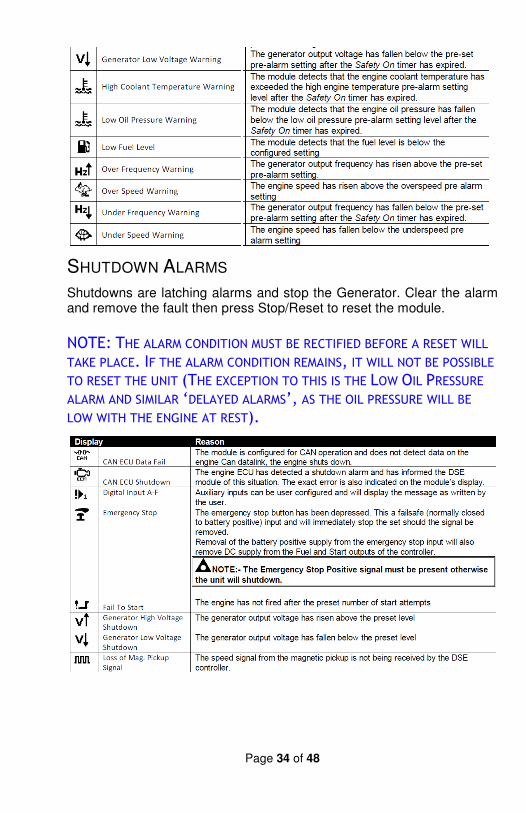
WARNINGS
Warnings are non-critical alarm conditions and do not affect the operation of the generator system, they serve to draw the operators attention to an undesirable condition.
In the event of an alarm the LCD will jump to the alarms page, and scroll through all active warnings and shutdowns.
Warning alarms are self-resetting when the fault condition is removed.
Page 34 of 48
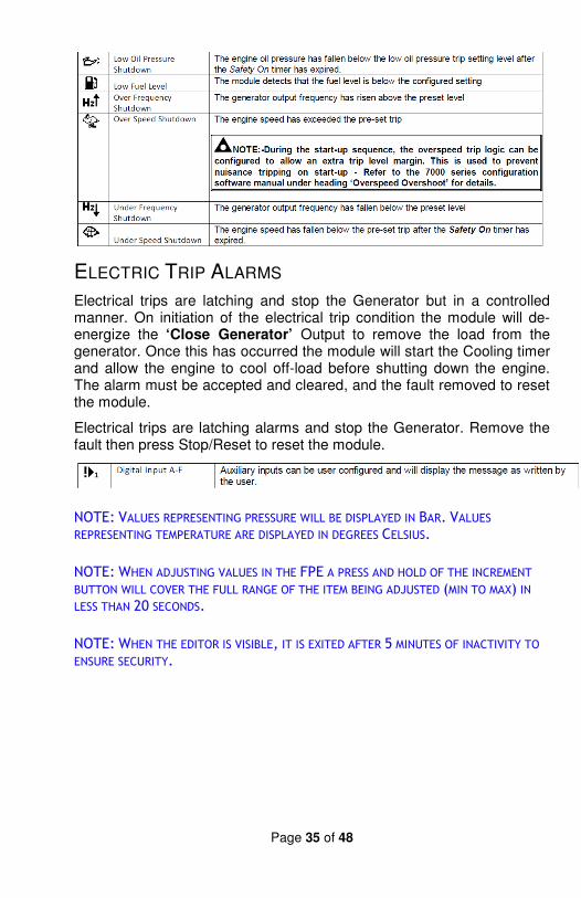
SHUTDOWN ALARMS
Shutdowns are latching alarms and stop the Generator. Clear the alarm and remove the fault then press Stop/Reset to reset the module.
NOTE: THE ALARM CONDITION MUST BE RECTIFIED BEFORE A RESET WILL
TAKE PLACE. IF THE ALARM CONDITION REMAINS, IT WILL NOT BE POSSIBLE
TO RESET THE UNIT (THE EXCEPTION TO THIS IS THE LOW OIL PRESSURE ALARM AND SIMILAR ‘DELAYED ALARMS’, AS THE OIL PRESSURE WILL BE
LOW WITH THE ENGINE AT REST).
Page 35 of 48
ELECTRIC TRIP ALARMS
Electrical trips are latching and stop the Generator but in a controlled manner. On initiation of the electrical trip condition the module will de-energize the ‘Close Generator’ Output to remove the load from the generator. Once this has occurred the module will start the Cooling timer and allow the engine to cool off-load before shutting down the engine. The alarm must be accepted and cleared, and the fault removed to reset the module.
Electrical trips are latching alarms and stop the Generator. Remove the fault then press Stop/Reset to reset the module.
NOTE: VALUES REPRESENTING PRESSURE WILL BE DISPLAYED IN BAR. VALUES REPRESENTING TEMPERATURE ARE DISPLAYED IN DEGREES CELSIUS.
NOTE: WHEN ADJUSTING VALUES IN THE FPE A PRESS AND HOLD OF THE INCREMENT BUTTON WILL COVER THE FULL RANGE OF THE ITEM BEING ADJUSTED (MIN TO MAX) IN LESS THAN 20 SECONDS.
NOTE: WHEN THE EDITOR IS VISIBLE, IT IS EXITED AFTER 5 MINUTES OF INACTIVITY TO ENSURE SECURITY.
Page 36 of 48
PC Configuration Interface Connector
Use a standard USB type A to type B cable. The USB connection cable between the PC and the 4400 series module must not be extended beyond 5m (5yds). For distances over 5m, it is possible to use a third party USB extender. Typically, they extend USB up to 50m (yards). The supply and support of this type of equipment is outside the scope of Deep Sea Electronics PLC.
CAUTION! CARE MUST BE TAKEN NOT TO OVERLOAD THE PCS USB SYSTEM BY CONNECTING MORE THAN THE RECOMMENDED NUMBER OF USB DEVICES TO THE PC. FOR FURTHER INFORMATION, CONSULT YOUR PC SUPPLIER. THE SOCKET MUST NOT BE USED FOR ANY OTHER PURPOSES.
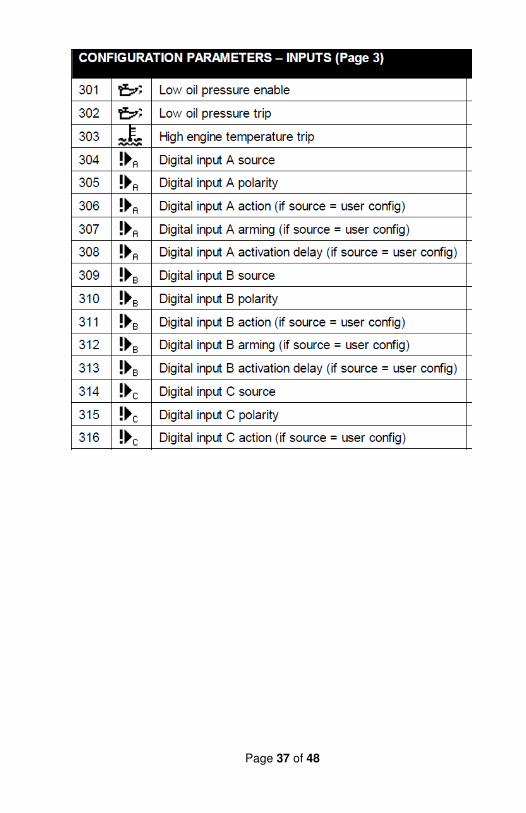
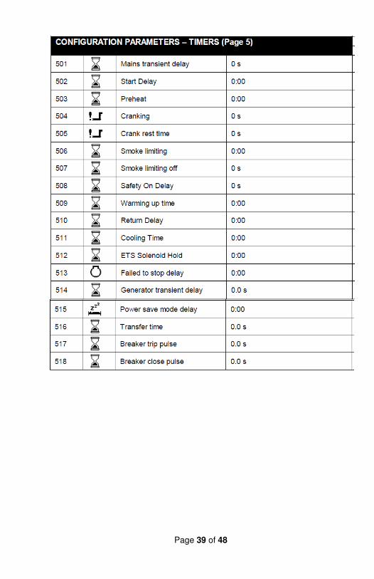
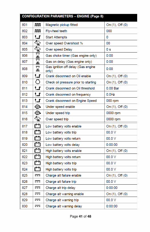
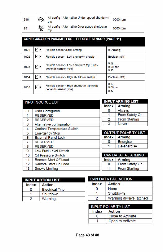
ADJUSTABLE PARAMETERS
Page 37 of 48
Page 38 of 48
Page 39 of 48
Page 40 of 48
Page 41 of 48
Page 42 of 48
Page 43 of 48
Page 44 of 48
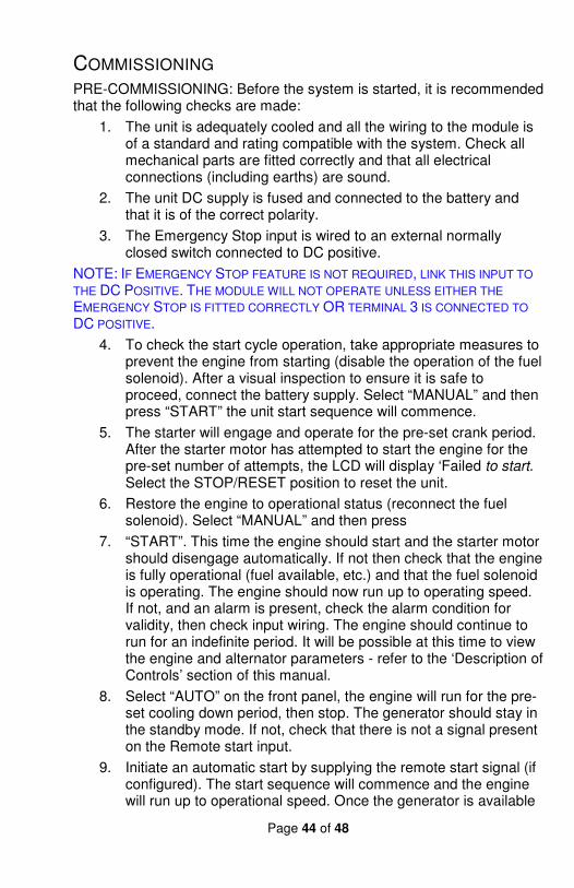
COMMISSIONING PRE-COMMISSIONING: Before the system is started, it is recommended that the following checks are made:
1. The unit is adequately cooled and all the wiring to the module is of a standard and rating compatible with the system. Check all mechanical parts are fitted correctly and that all electrical connections (including earths) are sound.
2. The unit DC supply is fused and connected to the battery and that it is of the correct polarity.
3. The Emergency Stop input is wired to an external normally closed switch connected to DC positive.
NOTE: IF EMERGENCY STOP FEATURE IS NOT REQUIRED, LINK THIS INPUT TO
THE DC POSITIVE. THE MODULE WILL NOT OPERATE UNLESS EITHER THE
EMERGENCY STOP IS FITTED CORRECTLY OR TERMINAL 3 IS CONNECTED TO
DC POSITIVE.
4. To check the start cycle operation, take appropriate measures to prevent the engine from starting (disable the operation of the fuel solenoid). After a visual inspection to ensure it is safe to proceed, connect the battery supply. Select “MANUAL” and then press “START” the unit start sequence will commence.
5. The starter will engage and operate for the pre-set crank period. After the starter motor has attempted to start the engine for the pre-set number of attempts, the LCD will display ‘Failed to start. Select the STOP/RESET position to reset the unit.
6. Restore the engine to operational status (reconnect the fuel solenoid). Select “MANUAL” and then press
7. “START”. This time the engine should start and the starter motor should disengage automatically. If not then check that the engine is fully operational (fuel available, etc.) and that the fuel solenoid is operating. The engine should now run up to operating speed. If not, and an alarm is present, check the alarm condition for validity, then check input wiring. The engine should continue to run for an indefinite period. It will be possible at this time to view the engine and alternator parameters - refer to the ‘Description of Controls’ section of this manual.
8. Select “AUTO” on the front panel, the engine will run for the pre-set cooling down period, then stop. The generator should stay in the standby mode. If not, check that there is not a signal present on the Remote start input.
9. Initiate an automatic start by supplying the remote start signal (if configured). The start sequence will commence and the engine will run up to operational speed. Once the generator is available
Page 45 of 48
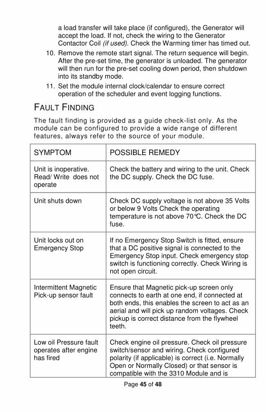
a load transfer will take place (if configured), the Generator will accept the load. If not, check the wiring to the Generator Contactor Coil (if used). Check the Warming timer has timed out.
10. Remove the remote start signal. The return sequence will begin. After the pre-set time, the generator is unloaded. The generator will then run for the pre-set cooling down period, then shutdown into its standby mode.
11. Set the module internal clock/calendar to ensure correct operation of the scheduler and event logging functions.
FAULT FINDING
The fault finding is provided as a guide check-list only. As the module can be configured to provide a wide range of different features, always refer to the source of your module.
SYMPTOM POSSIBLE REMEDY
Unit is inoperative. Read/ Write does not operate
Check the battery and wiring to the unit. Check the DC supply. Check the DC fuse.
Unit shuts down Check DC supply voltage is not above 35 Volts or below 9 Volts Check the operating temperature is not above 70°C. Check the DC fuse.
Unit locks out on Emergency Stop
If no Emergency Stop Switch is fitted, ensure that a DC positive signal is connected to the Emergency Stop input. Check emergency stop switch is functioning correctly. Check Wiring is not open circuit.
Intermittent Magnetic Pick-up sensor fault
Ensure that Magnetic pick-up screen only connects to earth at one end, if connected at both ends, this enables the screen to act as an aerial and will pick up random voltages. Check pickup is correct distance from the flywheel teeth.
Low oil Pressure fault operates after engine has fired
Check engine oil pressure. Check oil pressure switch/sensor and wiring. Check configured polarity (if applicable) is correct (i.e. Normally Open or Normally Closed) or that sensor is compatible with the 3310 Module and is
Page 46 of 48
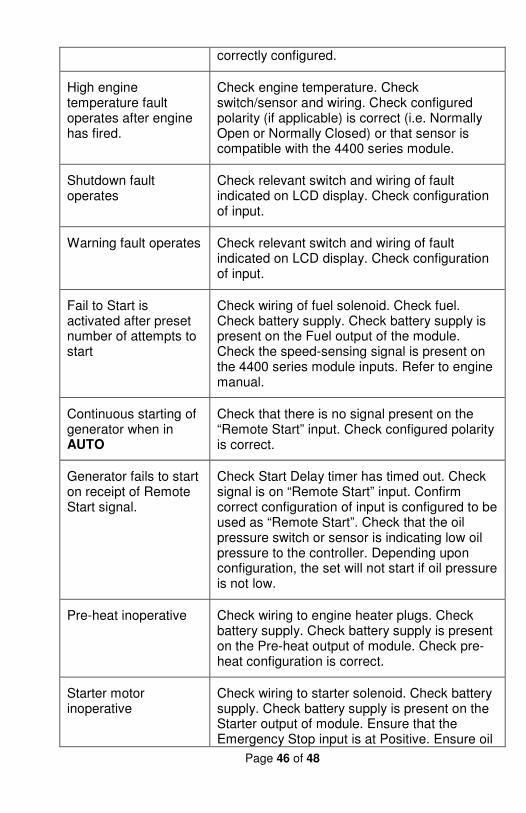
correctly configured.
High engine temperature fault operates after engine has fired.
Check engine temperature. Check switch/sensor and wiring. Check configured polarity (if applicable) is correct (i.e. Normally Open or Normally Closed) or that sensor is compatible with the 4400 series module.
Shutdown fault operates
Check relevant switch and wiring of fault indicated on LCD display. Check configuration of input.
Warning fault operates Check relevant switch and wiring of fault indicated on LCD display. Check configuration of input.
Fail to Start is activated after preset number of attempts to start
Check wiring of fuel solenoid. Check fuel. Check battery supply. Check battery supply is present on the Fuel output of the module. Check the speed-sensing signal is present on the 4400 series module inputs. Refer to engine manual.
Continuous starting of generator when in AUTO
Check that there is no signal present on the “Remote Start” input. Check configured polarity is correct.
Generator fails to start on receipt of Remote Start signal.
Check Start Delay timer has timed out. Check signal is on “Remote Start” input. Confirm correct configuration of input is configured to be used as “Remote Start”. Check that the oil pressure switch or sensor is indicating low oil pressure to the controller. Depending upon configuration, the set will not start if oil pressure is not low.
Pre-heat inoperative Check wiring to engine heater plugs. Check battery supply. Check battery supply is present on the Pre-heat output of module. Check pre-heat configuration is correct.
Starter motor inoperative
Check wiring to starter solenoid. Check battery supply. Check battery supply is present on the Starter output of module. Ensure that the Emergency Stop input is at Positive. Ensure oil
Page 47 of 48
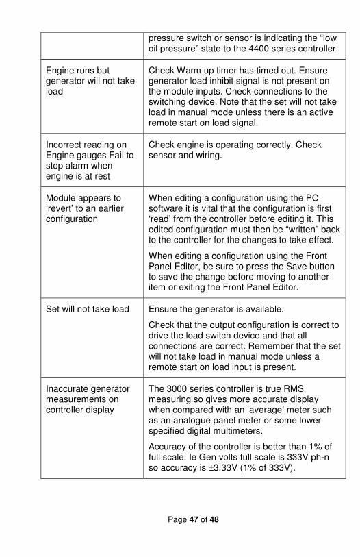
pressure switch or sensor is indicating the “low oil pressure” state to the 4400 series controller.
Engine runs but generator will not take load
Check Warm up timer has timed out. Ensure generator load inhibit signal is not present on the module inputs. Check connections to the switching device. Note that the set will not take load in manual mode unless there is an active remote start on load signal.
Incorrect reading on Engine gauges Fail to stop alarm when engine is at rest
Check engine is operating correctly. Check sensor and wiring.
Module appears to ‘revert’ to an earlier configuration
When editing a configuration using the PC software it is vital that the configuration is first ‘read’ from the controller before editing it. This edited configuration must then be “written” back to the controller for the changes to take effect.
When editing a configuration using the Front Panel Editor, be sure to press the Save button to save the change before moving to another item or exiting the Front Panel Editor.
Set will not take load Ensure the generator is available.
Check that the output configuration is correct to drive the load switch device and that all connections are correct. Remember that the set will not take load in manual mode unless a remote start on load input is present.
Inaccurate generator measurements on controller display
The 3000 series controller is true RMS measuring so gives more accurate display when compared with an ‘average’ meter such as an analogue panel meter or some lower specified digital multimeters.
Accuracy of the controller is better than 1% of full scale. Ie Gen volts full scale is 333V ph-n so accuracy is ±3.33V (1% of 333V).
Page 48 of 48
DC SUPPLY, FUEL, AND START OUTPUTS
Icons PIN DESCRIPTION NOTES
1 DC Plant Supply Input (Negative)
2 DC Plant Supply Input (Positive)
(Recommended Maximum Fuse 15A anti-surge) Supplies the module (2A anti-surge requirement) and all output relays
3 Output A (FUEL) Plant Supply Positive from terminal 2. 3 Amp rated. Normally used for FUEL control.
4 Output B (START)
Plant Supply Positive from terminal 2. 3 Amp rated. Normally used for START control.
5 Charge fail / excite
Do not connect to ground (battery negative). If charge alternator is not fitted, leave this terminal disconnected.
6 Output C
Plant Supply Positive from terminal 2. 3 Amp rated. Normally used for Generator load switch control.
7 Output D
Plant Supply Positive from terminal 2. 3 Amp rated. Normally used for Mains load switch control (DSE4420)
8 Output E Plant Supply Positive from terminal 2. 3 Amp rated.
9 Output F Plant Supply Positive from terminal 2. 3 Amp rated.