15
OPERATION MANUAL AND PARTS LIST HARD SURFACE TOOL NSS PART #4091341 NSS® Enterprises, Inc. 3115 Frenchmens Road Toledo, OH 43607 Phone: (419) 531-2121 Fax: (419) 531-3761 www.nss.com

OPERATION MANUAL AND PARTS LIST
HARD SURFACE TOOL
NSS PART #4091341
NSS® Enterprises, Inc. 3115 Frenchmens Road Toledo, OH 43607 Phone: (419) 531-2121 Fax: (419) 531-3761 www.nss.com
Important Safety Instructions
Intended Use
This product is intended to be used with the Rally 1200 hard surface cleaning machine for cleaning floors. This tool
may be used with other equipment. See instructions in this document for use with other equipment.
For Safety
Always read and understand all instructions before operating or servicing this tool.
Always use this machine only as described in this manual. Incorrect use of this tool may result in floor
damage or personal injury.
Never attempt to operate this tool unless you have been trained in its operation.
Never allow an untrained person to operate this tool.
Never attempt to operate this tool if it is not working properly or has been damaged in any manner.
Always wear clean tennis shoes or “non-slip” shoes. Leather soled shoes will be extremely slippery.
Never allow this tool to freeze.
Save These Instructions
Specifications
Model 4091341 Hard Surface Tool:
Cleaning Head: Width: 15 inches
Cleaning Head: Height: 3.13” w/ Hard Boot & 3.50” w/ Brush Ring
Total Height with Handle: 51 inches
Weight: 15.5 lbs.
Shell Construction: Polycarbonate
Hard Boot: HDPE
Brush Bristles: Nylon
Handle Construction: Stainless Steel
Maximum Solution Pressure: 1500 psi
Minimum Solution Pressure: 700 psi
Maintenance
To keep this tool looking and working its best for the longest period of use:
After each use rinse the Inner Shell of the tool to remove accumulated dirt and debris. The Inner Shell can be separated from the Outer Shell to clean the air flow channel between the two shells.
Rinse and wipe down top of head assembly and handle.
Rinse and wipe clean the Hard Boot or the Brush Ring.
Examine Hard Boot - Replace the Hard Boot if worn down or deep gouges and embedded debris are found.
Examine the Brush Ring - Replace Brush ring if bristles are excessively bent, worn or if too many bristles are missing.
Check and clean the stainless steel mesh filter between the quick connect and valve to prevent a reduction in water flow and tool efficiency.
Check the spray pattern of the jets and clean or replace the jets as needed to assure even spray pattern.
Check vacuum hose for holes or cracks.
Replace vacuum hose as needed.
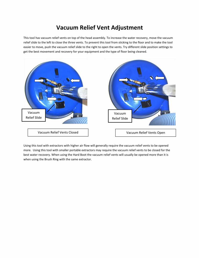
Vacuum Relief Vent Adjustment
This tool has vacuum relief vents on top of the head assembly. To increase the water recovery, move the vacuum
relief slide to the left to close the three vents. To prevent this tool from sticking to the floor and to make the tool
easier to move, push the vacuum relief slide to the right to open the vents. Try different slide position settings to
get the best movement and recovery for your equipment and the type of floor being cleaned.
Using this tool with extractors with higher air flow will generally require the vacuum relief vents to be opened
more. Using this tool with smaller portable extractors may require the vacuum relief vents to be closed for the
best water recovery. When using the Hard Boot the vacuum relief vents will usually be opened more than it is
when using the Brush Ring with the same extractor.
Vacuum Relief Vents Closed Vacuum Relief Vents Open
Vacuum
Relief Slide Vacuum
Relief Slide
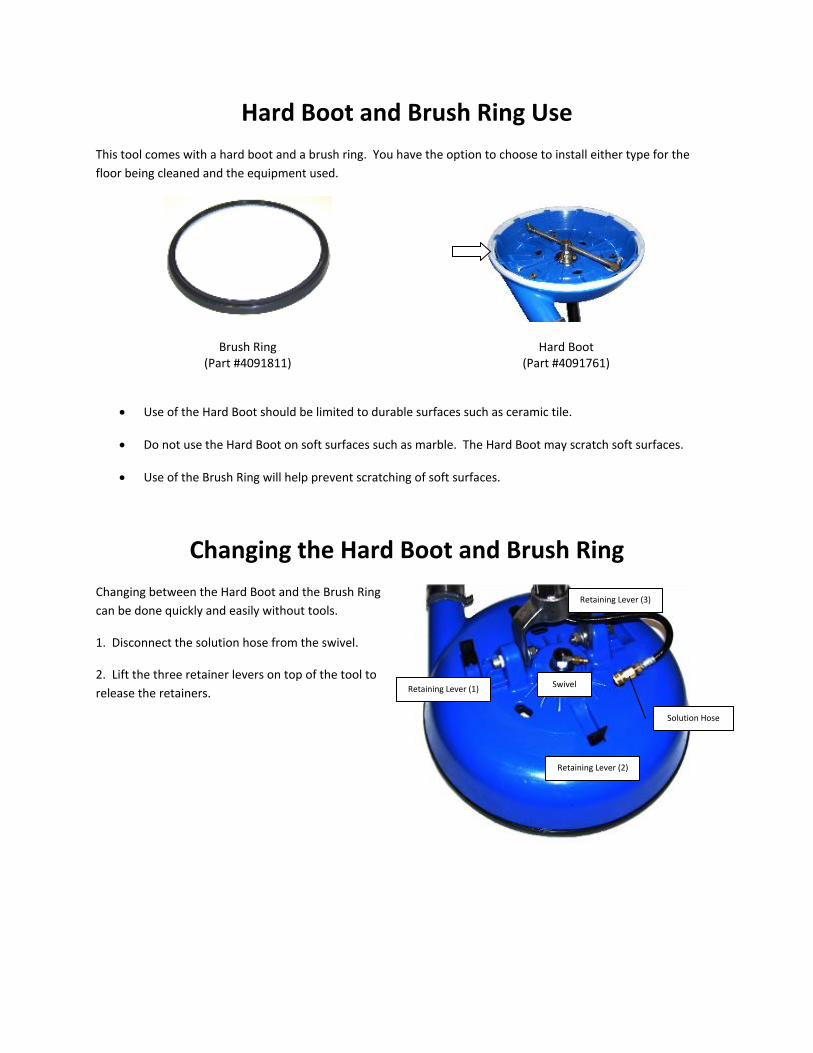
Hard Boot and Brush Ring Use
This tool comes with a hard boot and a brush ring. You have the option to choose to install either type for the
floor being cleaned and the equipment used.
Brush Ring (Part #4091811)
Hard Boot (Part #4091761)
Use of the Hard Boot should be limited to durable surfaces such as ceramic tile.
Do not use the Hard Boot on soft surfaces such as marble. The Hard Boot may scratch soft surfaces.
Use of the Brush Ring will help prevent scratching of soft surfaces.
Changing the Hard Boot and Brush Ring
Changing between the Hard Boot and the Brush Ring
can be done quickly and easily without tools.
1. Disconnect the solution hose from the swivel.
2. Lift the three retainer levers on top of the tool to
release the retainers.
Solution Hose
Retaining Lever (1)
Retaining Lever (2)
Retaining Lever (3)
Swivel

3. Turn the deck over and turn the three rectangular retaining nuts on the retainers to align with the holes in the
bottom of the Inner Shell, so they can pass through the holes.
Three rectangular retaining nuts Retaining nut aligned for inner shell removal
4. Pull and separate the inner shell from the outer shell
5. Lift up and remove the Hard Boot or Brush Ring from the bottom
lip of the outer shell.
6. Place either the Brush Ring or the Hard Boot on to the bottom lip
of the Outer Shell.
7. Place the Inner Shell back onto the Outer Shell with the
rectangular retaining nuts going through the openings in the Inner
Shell. The flanges on the Inner Shell set on the edge of the Hard
Boot or Brush Ring to hold it in place.

8. Turn the rectangular retaining nuts perpendicular to the slots in
the bottom of the Inner Shell. Retaining nuts may need to be
tightened so that they each contact the plastic surface of the inner
shell when the retaining levers are pushed back down to assure that
the assembly is secured properly.
9. Turn the head assembly back over and snap the three retaining
levers back down to secure the Outer and Inner Shells. Check the
retaining nuts to be sure all three are in contact with the plastic
Inner Shell. Open the retaining levers and tighten retaining nuts as
needed to assure that the Inner Shell is properly secured when the
levers are pushed down.
10. Reconnect the solution hose to the swivel.
Using this tool with other equipment
This tool will work with portable or truck mounted extractors, but the water recovery may be better with higher
powered extractors with more air flow. The extractor solution pump must provide a minimum of 700 psi of water
pressure with a flow rate of at least 1.5 gpm (Gallon Per Minute). At 1000 psi the flow rate must exceed 2.0 gpm
and at 1500 psi the flow rate must exceed 3.0 gpm.
The recommended pressure for tool operation is 700 to 1200 psi.
Set-up Procedure
1. Install the Hard Boot or Brush ring on the tool.
2. Connect the vacuum hose from your extractor to the vacuum pipe on the tool handle. A 2” cuff will fit
over the pipe, a 1-1/2” cuff will fit inside the pipe.
3. Connect the solution hose from the extractor to the quick connect on the valve assembly.
4. Turn the extractor on. Adjust the water pressure to the desired value. Minimum pressure: 700 psi.
Maximum pressure: 1500 psi.
5. Adjust the vacuum relief slide for best recovery and ease of movement.
Basic Cleaning Procedure
Remove all furniture from the area you are going to clean. Sweep or vacuum the floor to remove dust and grit,
pieces of glass, sand, etc.
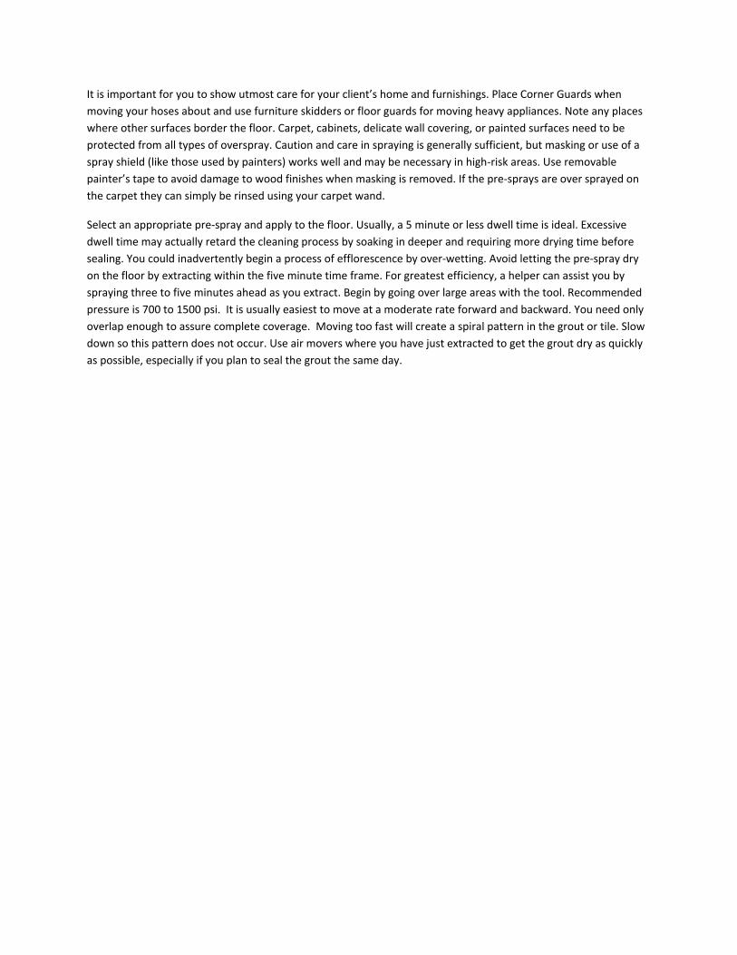
It is important for you to show utmost care for your client’s home and furnishings. Place Corner Guards when
moving your hoses about and use furniture skidders or floor guards for moving heavy appliances. Note any places
where other surfaces border the floor. Carpet, cabinets, delicate wall covering, or painted surfaces need to be
protected from all types of overspray. Caution and care in spraying is generally sufficient, but masking or use of a
spray shield (like those used by painters) works well and may be necessary in high-risk areas. Use removable
painter’s tape to avoid damage to wood finishes when masking is removed. If the pre-sprays are over sprayed on
the carpet they can simply be rinsed using your carpet wand.
Select an appropriate pre-spray and apply to the floor. Usually, a 5 minute or less dwell time is ideal. Excessive
dwell time may actually retard the cleaning process by soaking in deeper and requiring more drying time before
sealing. You could inadvertently begin a process of efflorescence by over-wetting. Avoid letting the pre-spray dry
on the floor by extracting within the five minute time frame. For greatest efficiency, a helper can assist you by
spraying three to five minutes ahead as you extract. Begin by going over large areas with the tool. Recommended
pressure is 700 to 1500 psi. It is usually easiest to move at a moderate rate forward and backward. You need only
overlap enough to assure complete coverage. Moving too fast will create a spiral pattern in the grout or tile. Slow
down so this pattern does not occur. Use air movers where you have just extracted to get the grout dry as quickly
as possible, especially if you plan to seal the grout the same day.

Hard Surface Tool Part List
--
Decal (4091671)
Spray Gun (4091371)
Handle SS (4091681)
Spray Gun, Body Only (4091711)
Hose Clamp (4091691)
Hose Clamp (4091691)
Vacuum Hose 2” ID x 3’ Long (4091751)

--
Swivel w/ Flange (4091781)
Outer Shell (4091701)
Swell Latch (Qty 3) (4091801)
Brush Ring (4091811)
Solution Hose HP 3/16” ID x 50”, 1/8 MPT
1/8” MPT and 1/4” MPT Ends (4091821)
--
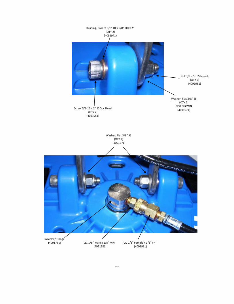
Bushing, Bronze 3/8” ID x 5/8” OD x 2” (QTY 2)
(4091941)
Screw 3/8-16 x 2” SS Soc Head (QTY 2)
(4091951)
Nut 3/8 – 16 SS Nylock (QTY 2)
(4091961)
Washer, Flat 3/8” SS (QTY 2)
NOT SHOWN (4091971)
Washer, Flat 3/8” SS (QTY 2)
(4091971)
Swivel w/ Flange (4091781) QC 1/8” Male x 1/8” MPT
(4091981) QC 1/8” Female x 1/8” FPT
(4091991)
--
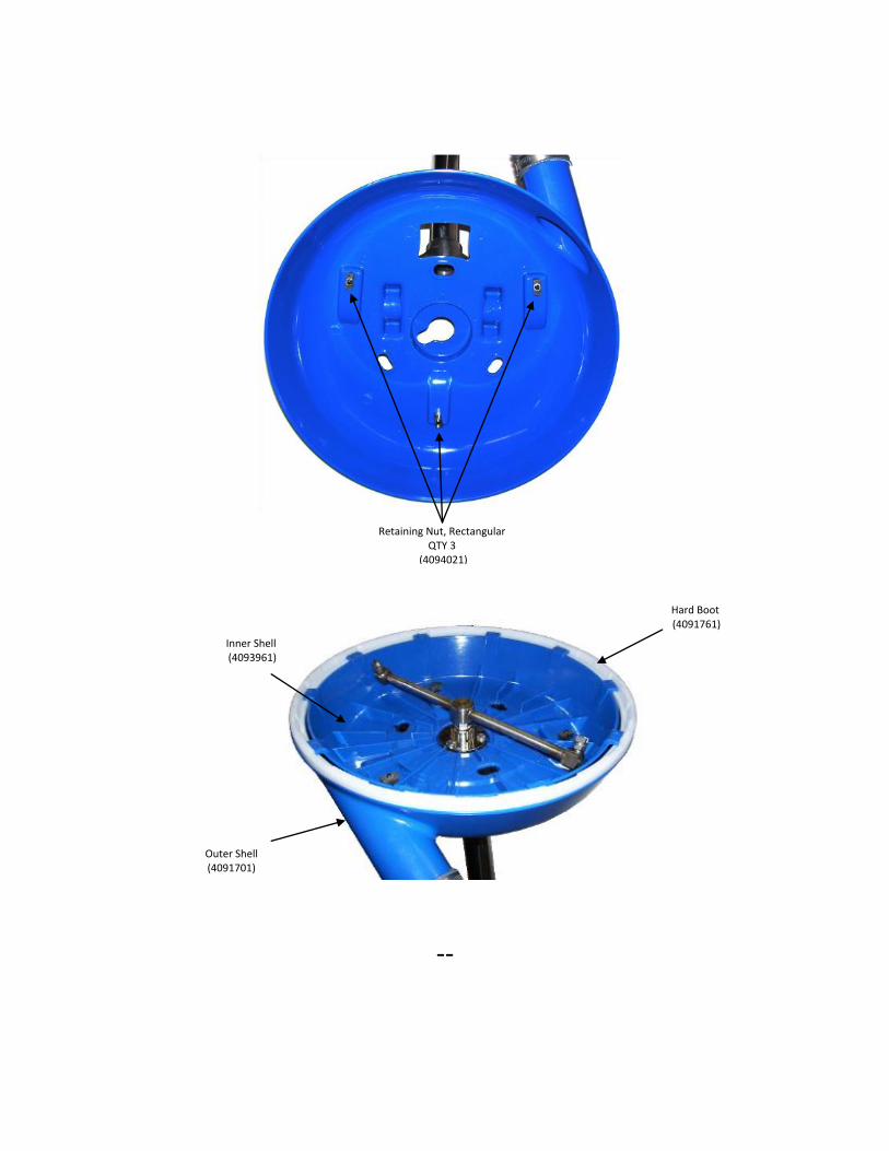
Retaining Nut, Rectangular QTY 3
(4094021)
Hard Boot (4091761)
Inner Shell (4093961)
Outer Shell (4091701)
--
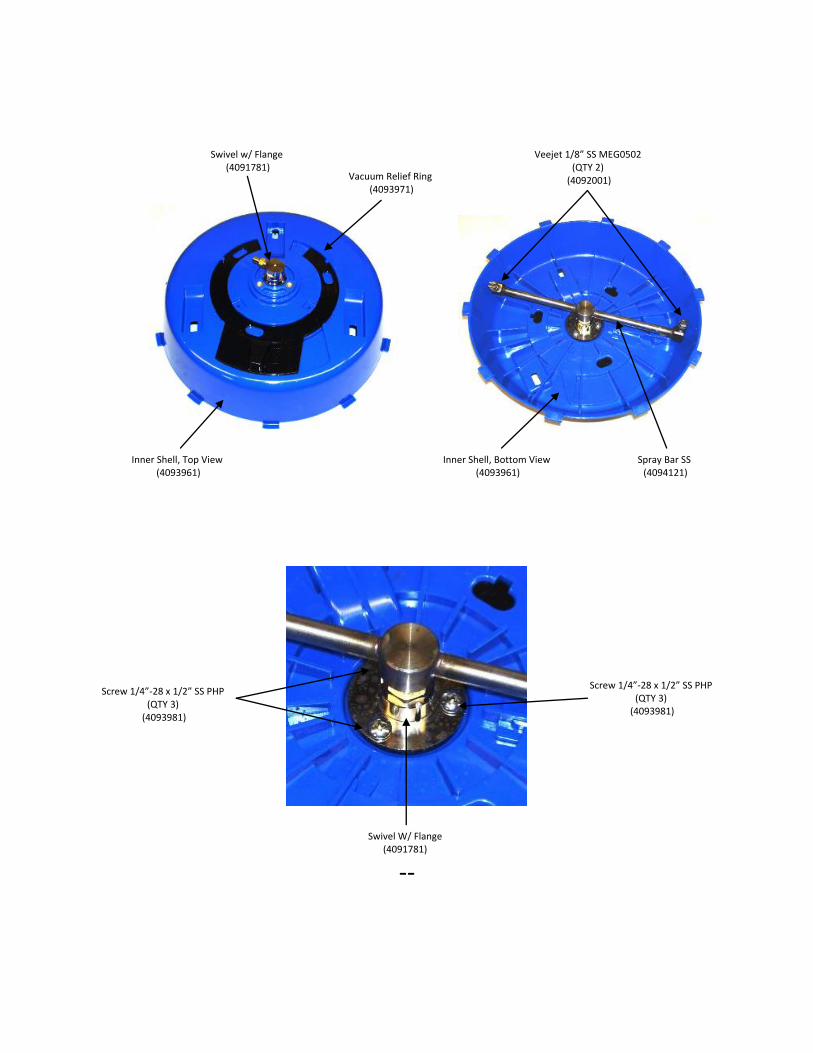
Swivel w/ Flange (4091781)
Vacuum Relief Ring (4093971)
Inner Shell, Top View (4093961)
Inner Shell, Bottom View (4093961)
Veejet 1/8” SS MEG0502 (QTY 2)
(4092001)
Spray Bar SS (4094121)
Screw 1/4”-28 x 1/2” SS PHP (QTY 3)
(4093981)
Screw 1/4”-28 x 1/2” SS PHP (QTY 3)
(4093981)
Swivel W/ Flange (4091781)

--
Grommet (4094001)
End Cap (4093991)
Spray Gun, Body Only (4091711)
Spray Gun (4091371)
Nut 10-32 Nylock (QTY 6)
(4093931)
Nut 10-32 Nylock (QTY 6)
(4093931)
Solution Hose HP 3/16” ID x 50”, 1/8 MPT
1/8” MPT and 1/4” MPT Ends (4091821)
Spray Gun (4091371)
Spray Gun, Body Only (4091711)
Screw 10-32 x 1-5/8” BHSOC SS (QTY 6)
(4093941)
QC 1/4” Male (4091771)

--
Spray Gun (4091371)
QC 1/4” Male (4091771)
Strainer Body (4093231)
Strainer 50 SS (4093911)
Strainer Adapter (4093921)
Elbow 90 1/4” Street (4093061)
Elbow 45 1/4” Street (4094221)
Replacement Valve for Spray Gun (4093081)
Spray Gun Valve Repair Kit (4093221)
Valve Repair Kit Contains: Spring SS Ball Seat
Seat O-Ring Stem
Stem O-Ring Back-Up Rings (Qty 2)
Cap O-Ring Valve Cap
Hard Surface Tool, Operation Manual and Parts List 9094071 Rev Original 8-15


