IMPORTANT Test drive vehicle after service to verify proper brake system performance. OPERATION MANUAL BFX-2 Brake Fluid Exchanger RTI Technologies, Inc. 10 Innovation Drive York, Pennsylvania 17402 USA Phone: 800-468-2321 Web-site: www.rtitech.com 035-81327-00
Transcript
IMPORTANTTest drive vehicle after service to verify proper
EC Declaration of Conformity for Machinery . . . . . . . . . 11
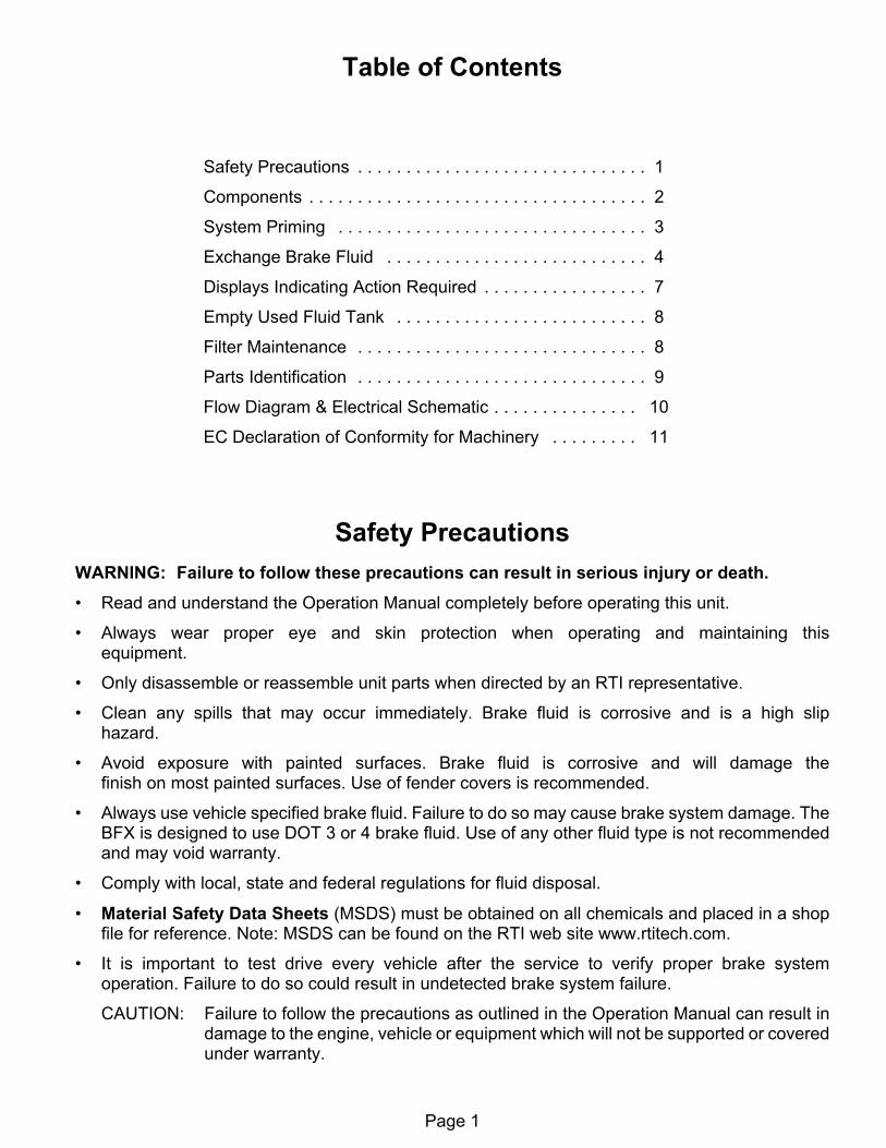
Safety PrecautionsWARNING: Failure to follow these precautions can result in serious injury or death.• Read and understand the Operation Manual completely before operating this unit.
• Always wear proper eye and skin protection when operating and maintaining thisequipment.
• Only disassemble or reassemble unit parts when directed by an RTI representative.
• Clean any spills that may occur immediately. Brake fluid is corrosive and is a high sliphazard.
• Avoid exposure with painted surfaces. Brake fluid is corrosive and will damage thefinish on most painted surfaces. Use of fender covers is recommended.
• Always use vehicle specified brake fluid. Failure to do so may cause brake system damage. TheBFX is designed to use DOT 3 or 4 brake fluid. Use of any other fluid type is not recommendedand may void warranty.
• Comply with local, state and federal regulations for fluid disposal.
• Material Safety Data Sheets (MSDS) must be obtained on all chemicals and placed in a shopfile for reference. Note: MSDS can be found on the RTI web site www.rtitech.com.
• It is important to test drive every vehicle after the service to verify proper brake systemoperation. Failure to do so could result in undetected brake system failure.
CAUTION: Failure to follow the precautions as outlined in the Operation Manual can result indamage to the engine, vehicle or equipment which will not be supported or coveredunder warranty.
Page 2
560-
8037
9-00
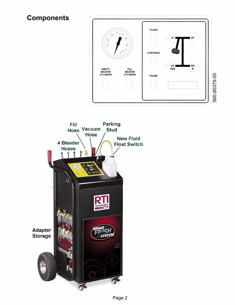
EMPTYMASTER
CYLINDER
FILLMASTER
CYLINDER
FLUSH
LF RF
RRLR
CONTINUE
PAUSE
ABS
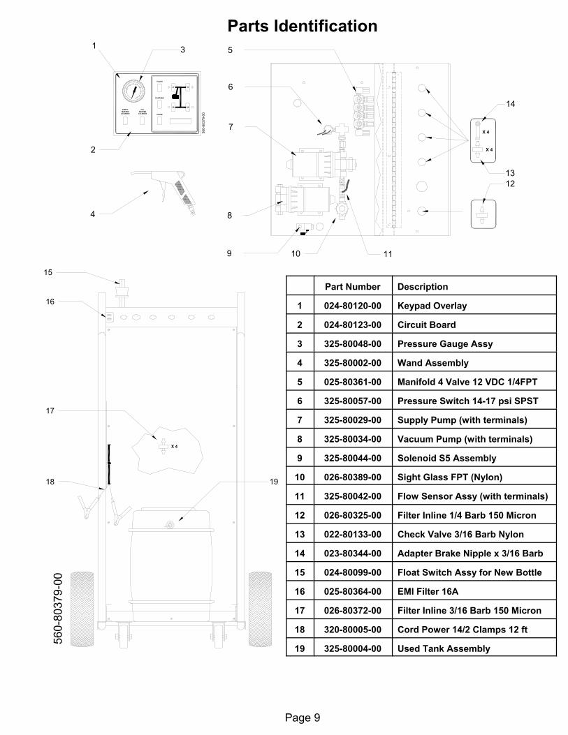
Components
Page 3
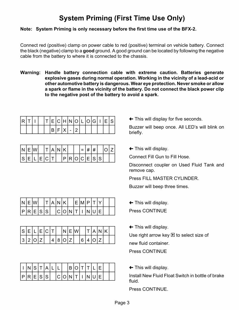
System Priming (First Time Use Only)Note: System Priming is only necessary before the first time use of the BFX-2.
Connect red (positive) clamp on power cable to red (positive) terminal on vehicle battery. Connectthe black (negative) clamp to a good ground. A good ground can be located by following the negativecable from the battery to where it is connected to the chassis.
Warning: Handle battery connection cable with extreme caution. Batteries generateexplosive gases during normal operation. Working in the vicinity of a lead-acid orother automotive battery is dangerous. Wear eye protection. Never smoke or allowa spark or flame in the vicinity of the battery. Do not connect the black power clipto the negative post of the battery to avoid a spark.
R T I T E C H N O L O G I E S
B F X - 2
N E W T A N K = # # O Z
S E L E C T P R O C E S S
N E W T A N K E M P T Y
P R E S S C O N T I N U E
S E L E C T N E W T A N K
3 2 O Z 4 8 O Z 6 4 O Z
I N S T A L L B O T T L E
P R E S S C O N T I N U E
³ This will display for five seconds.
Buzzer will beep once. All LED’s will blink onbriefly.
³ This will display.
Connect Fill Gun to Fill Hose.
Disconnect coupler on Used Fluid Tank andremove cap.
Press FILL MASTER CYLINDER.
Buzzer will beep three times.
³ This will display.
Press CONTINUE
³ This will display.
Use right arrow key | to select size of
new fluid container.
Press CONTINUE
³ This will display.
Install New Fluid Float Switch in bottle of brakefluid.
Press CONTINUE.
Page 4
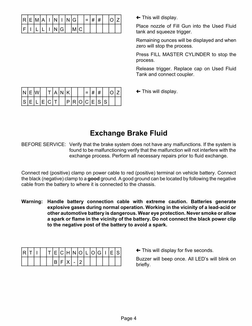
R E M A I N I N G = # # O Z
F I L L I N G M C
N E W T A N K = # # O Z
S E L E C T P R O C E S S
³ This will display.
Place nozzle of Fill Gun into the Used Fluidtank and squeeze trigger.
Remaining ounces will be displayed and whenzero will stop the process.
Press FILL MASTER CYLINDER to stop theprocess.
Release trigger. Replace cap on Used FluidTank and connect coupler.
³ This will display.
Exchange Brake FluidBEFORE SERVICE: Verify that the brake system does not have any malfunctions. If the system is
found to be malfunctioning verify that the malfunction will not interfere with theexchange process. Perform all necessary repairs prior to fluid exchange.
Connect red (positive) clamp on power cable to red (positive) terminal on vehicle battery. Connectthe black (negative) clamp to a good ground. A good ground can be located by following the negativecable from the battery to where it is connected to the chassis.
Warning: Handle battery connection cable with extreme caution. Batteries generateexplosive gases during normal operation. Working in the vicinity of a lead-acid orother automotive battery is dangerous. Wear eye protection. Never smoke or allowa spark or flame in the vicinity of the battery. Do not connect the black power clipto the negative post of the battery to avoid a spark.
R T I T E C H N O L O G I E S
B F X - 2
³ This will display for five seconds.
Buzzer will beep once. All LED’s will blink onbriefly.
Page 5
N E W T A N K = # # O Z
S E L E C T P R O C E S S
N E W T A N K = # # O Z
E M P T Y I N G M C
N E W T A N K = # # O Z
S E L E C T P R O C E S S
S E L E C T N E W T A N K
3 2 O Z 4 8 O Z 6 4 O Z
I N S T A L L B O T T L E
P R E S S C O N T I N U E
R E M A I N I N G = # # O Z
F I L L I N G M C
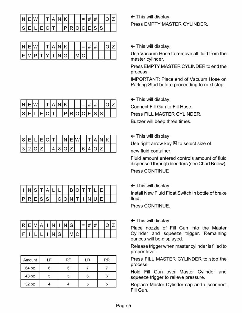
Amount LF RF LR RR
64 oz 6 6 7 7
48 oz 5 5 6 6
32 oz 4 4 5 5
³ This will display.Press EMPTY MASTER CYLINDER.
³ This will display.Use Vacuum Hose to remove all fluid from themaster cylinder.Press EMPTY MASTER CYLINDER to end theprocess.IMPORTANT: Place end of Vacuum Hose onParking Stud before proceeding to next step.
³ This will display.Connect Fill Gun to Fill Hose.Press FILL MASTER CYLINDER.Buzzer will beep three times.
³ This will display.Use right arrow key | to select size ofnew fluid container.Fluid amount entered controls amount of fluiddispensed through bleeders (see Chart Below).Press CONTINUE
³ This will display.Install New Fluid Float Switch in bottle of brakefluid.Press CONTINUE.
³ This will display.Place nozzle of Fill Gun into the MasterCylinder and squeeze trigger. Remainingounces will be displayed.Release trigger when master cylinder is filled toproper level.Press FILL MASTER CYLINDER to stop theprocess.Hold Fill Gun over Master Cylinder andsqueeze trigger to relieve pressure.Replace Master Cylinder cap and disconnectFill Gun.
Page 6
N E W T A N K = # # O Z
S E L E C T P R O C E S S
E N T E R S E Q U E N C E
X X - X X - X X - X X
O P E N B L E E D E R S
P R E S S > C O N T I N U E <
R E M A I N I N G = # # O Z
B L E E D I N G X X
P R E S S > C O N T I N U E <
C L O S E B L E E D E R S
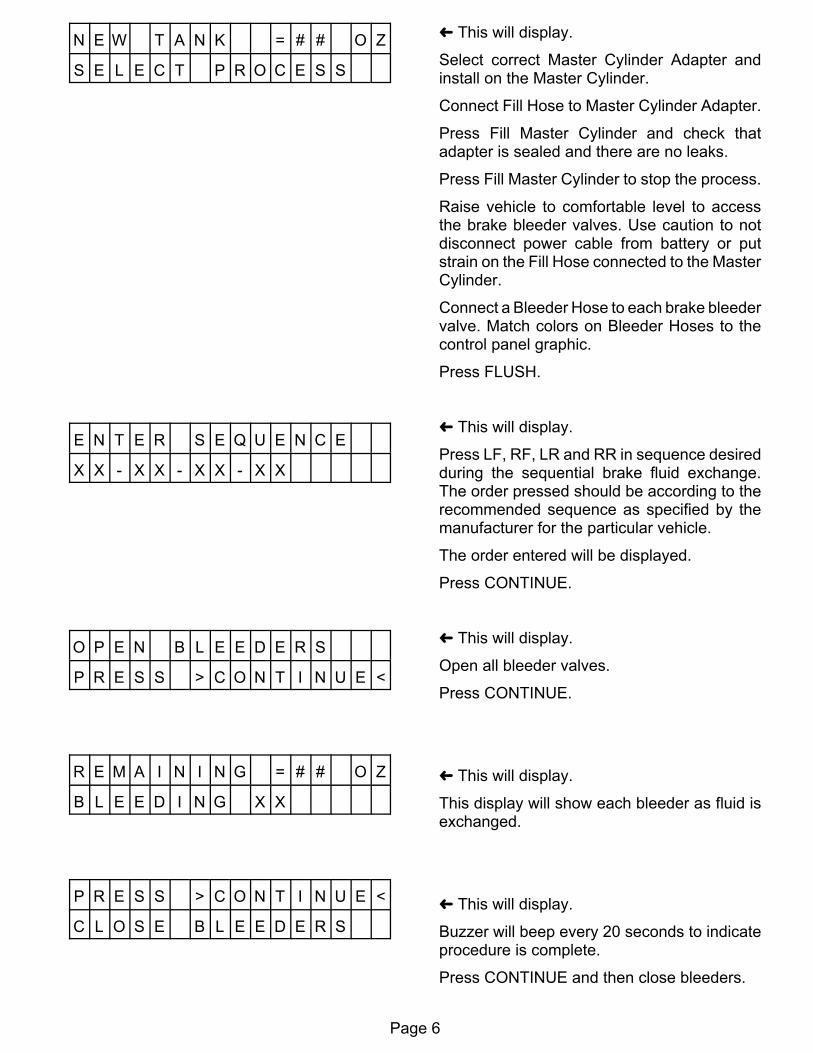
³ This will display.
Select correct Master Cylinder Adapter andinstall on the Master Cylinder.
Connect Fill Hose to Master Cylinder Adapter.
Press Fill Master Cylinder and check thatadapter is sealed and there are no leaks.
Press Fill Master Cylinder to stop the process.
Raise vehicle to comfortable level to accessthe brake bleeder valves. Use caution to notdisconnect power cable from battery or putstrain on the Fill Hose connected to the MasterCylinder.
Connect a Bleeder Hose to each brake bleedervalve. Match colors on Bleeder Hoses to thecontrol panel graphic.
Press FLUSH.
³ This will display.
Press LF, RF, LR and RR in sequence desiredduring the sequential brake fluid exchange.The order pressed should be according to therecommended sequence as specified by themanufacturer for the particular vehicle.
The order entered will be displayed.
Press CONTINUE.
³ This will display.
Open all bleeder valves.
Press CONTINUE.
³ This will display.
This display will show each bleeder as fluid isexchanged.
³ This will display.
Buzzer will beep every 20 seconds to indicateprocedure is complete.
Press CONTINUE and then close bleeders.
Page 7
P R E S S > F L U S H <
W H E N F I N I S H E D
D R A I N F L U I D Y / N
P R E S S C O N T I N U E
C L E A R I N G P R O C E S S
R U N N I N G , W A I T
P L E A S E W A I T
N E W T A N K = # # O Z
S E L E C T P R O C E S S
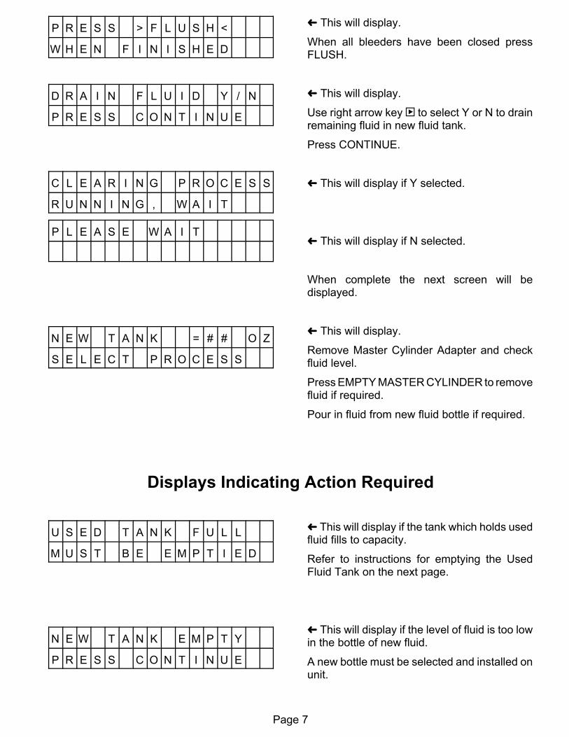
³ This will display.
When all bleeders have been closed pressFLUSH.
³ This will display.
Use right arrow key | to select Y or N to drainremaining fluid in new fluid tank.
Press CONTINUE.
³ This will display if Y selected.
³ This will display if N selected.
When complete the next screen will bedisplayed.
³ This will display.
Remove Master Cylinder Adapter and checkfluid level.
Press EMPTY MASTER CYLINDER to removefluid if required.
Pour in fluid from new fluid bottle if required.
Displays Indicating Action Required
U S E D T A N K F U L L
M U S T B E E M P T I E D
N E W T A N K E M P T Y
P R E S S C O N T I N U E
³ This will display if the tank which holds usedfluid fills to capacity.
Refer to instructions for emptying the UsedFluid Tank on the next page.
³ This will display if the level of fluid is too lowin the bottle of new fluid.
A new bottle must be selected and installed onunit.
Page 8
Empty Used Fluid Tank1. Disconnect the fluid line coupler and the electrical float switch cable on the Used Fluid Tank.
2. Remove cap on Used Fluid Tank (turn counterclockwise).
3. Empty used fluid into an appropriate bulk waste container.
4. Replace cap on Used Fluid Tank (turn clockwise).
5. Connect fluid line coupler and the electrical float switch cable.
Follow all federal and local laws and regulations when disposing of hazardous material.
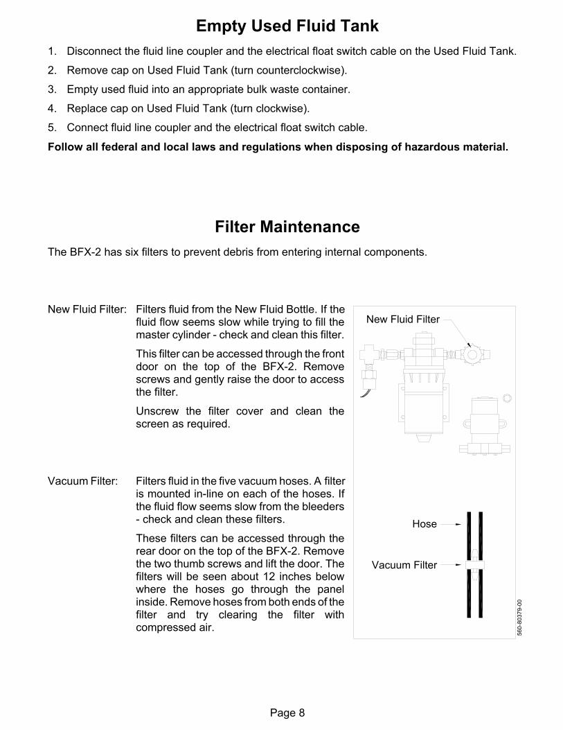
Filter MaintenanceThe BFX-2 has six filters to prevent debris from entering internal components.
New Fluid Filter: Filters fluid from the New Fluid Bottle. If thefluid flow seems slow while trying to fill themaster cylinder - check and clean this filter.
This filter can be accessed through the frontdoor on the top of the BFX-2. Removescrews and gently raise the door to accessthe filter.
Unscrew the filter cover and clean thescreen as required.
Vacuum Filter: Filters fluid in the five vacuum hoses. A filteris mounted in-line on each of the hoses. Ifthe fluid flow seems slow from the bleeders- check and clean these filters.
These filters can be accessed through therear door on the top of the BFX-2. Removethe two thumb screws and lift the door. Thefilters will be seen about 12 inches belowwhere the hoses go through the panelinside. Remove hoses from both ends of thefilter and try clearing the filter withcompressed air.