104
Operation Manual for Model SP 305 Operation Manual Version 5.0.1 Part Number 30362000 Copyright © 2011, Schwing America, Inc. All rights reserved

Operation Manual for
Model SP 305
Operation Manual
Version 5.0.1
Part Number 30362000
Copyright © 2011, Schwing America, Inc.All rights reserved

Table of Contents
Operation Manual - SP 305ii
revDate
INTRODUCTION
Manufacturer’s Statement........................................................................... 6Safety alert symbol and signal word explanation ................................. 6How to reach us .................................................................................... 7How to order parts ................................................................................ 7
Model Number ............................................................................................ 7Serial Number ............................................................................................. 7
Orientation ............................................................................................ 7Model Number Nomenclature .................................................................... 8
SP 305 ................................................................................................... 8ID Tags ....................................................................................................... 8
Main ID tag........................................................................................... 9If your ID tag is missing ....................................................................... 9
SPECIFICATIONS
SP 305 ....................................................................................................... 12Functional Description of the Main Control Block .................................. 13
SAFETY
How to Order Additional Safety Manuals ................................................ 16Warning Labels (Decals) .......................................................................... 19
OPERATION
Preparing for the Job................................................................................. 22Towing the unit ................................................................................... 22
Setting Up ................................................................................................. 23Arrival at the job ................................................................................. 23Laying pipe ......................................................................................... 23Starting the engine .............................................................................. 24Controlling the pump .......................................................................... 25The control panel ................................................................................ 25The remote control box....................................................................... 27Note about the electric system ............................................................ 27The volume control knob.................................................................... 27Throttle control ................................................................................... 27The pressure gauge ............................................................................. 27
Starting the Pour ....................................................................................... 27Concrete mixes ................................................................................... 27Preparing for concrete......................................................................... 27Ready the pump .................................................................................. 28Mix your slurry ................................................................................... 28Beginning to pump.............................................................................. 28
Cleanout .................................................................................................... 31Clean the delivery system ................................................................... 31Clean the pump ................................................................................... 32
Special Pumping Situations ...................................................................... 34

Table of Contents
SP 305
Startup 250:Users:Danny:Desktop:Operation manuals:line pumps:maverick (P305):pHseriesTOC.fm
Operation Manual - iii
Plugs.................................................................................................... 34Cold weather pumping........................................................................ 35Hot weather pumping.......................................................................... 36Emergency procedures........................................................................ 36Other Things You Need to Know ....................................................... 37
MAINTENANCE
Filtration.................................................................................................... 40General information ............................................................................ 40Specific information............................................................................ 40To change the element ........................................................................ 41
Hydraulic Oils........................................................................................... 41General information ............................................................................ 41Specific information............................................................................ 42When to change your hydraulic oil ..................................................... 42
Pressure, Hoses and Fittings ..................................................................... 42General Information............................................................................ 42Specific Information ........................................................................... 43
General Maintenance Tips ........................................................................ 44Torque specifications .......................................................................... 44Adjusting relief valves ........................................................................ 44Removal of safety devices .................................................................. 44
Preventative Maintenance......................................................................... 45Daily maintenance .............................................................................. 45Monthly maintenance.......................................................................... 47Semiannual maintenance (every 6 months) ........................................ 48Annual maintenance............................................................................ 49Scheduled maintenance checklist ....................................................... 57
Unscheduled Maintenance ........................................................................ 58Wear parts ........................................................................................... 58Changing rams .................................................................................... 58
APPENDIX
Hydraulic Oil Viscosity Chart .................................................................. 62Torque Specifications for SAE Bolts........................................................ 63Recommended Emergency Hose Kit ........................................................ 64Fitting Wrench Sizes................................................................................. 64Maintenance Checklist.............................................................................. 66Weld-on Ends / Coupling Comparison ..................................................... 67Output Charts ............................................................................................ 68
Using the chart .................................................................................... 68Using a Nomograph .................................................................................. 74
General information ............................................................................ 74The quadrants...................................................................................... 76
Minimum Pipe Wall Thickness ................................................................ 82Pictograms................................................................................................. 83Decal Location Guide ............................................................................... 84

Table of Contents
Operation Manual - SP 305iv
revDate
Glossary of Terms..................................................................................... 86Additional Reading Material .............................................................. 90
List of Lubricants and Nitrogen................................................................ 91Hydraulic Schematic—Concrete Pump SP305 - Schematic..................... 95Electrical Schematic SP305 - 2004 Electric ............................................. 96Electric Schematic CE/Tier III SP305 ...................................................... 97Nomograph SP 305................................................................................... 98Output Chart available upon request ........................................................ 99
INDEX
Alphabetical Index.................................................................................. 102

SP 305 OPERATION MANUAL
Introduction 5
INTRODUCTION
Manufacturer’s Statement........................................................................ 6 Model Number ......................................................................................... 7 Serial Number.......................................................................................... 7 Model Number Nomenclature.................................................................. 8 ID Tags..................................................................................................... 8

Introduction
Operation Manual - SP 3056
8/4/11
INTRODUCTION
This operation manual contains unit specifications,product overview information, the
Safety Manual
,operation information, and maintenance informationfor your concrete pump unit.
Manufacturer’s Statement
The information contained in the operation manual isabsolutely necessary for the safety, proper setup,operation, maintenance, and servicing of your concretepump. By learning this information and practicing itevery day, you can expect that your concrete pump unitwill give you efficient and reliable service year afteryear.
For your own benefit and safety, read the information inthis manual, and follow the instructions to the letter.
Before you operate your concrete pump for the firsttime, you should read the operating instructions severaltimes through. We recommend that you keep a copywith the concrete pump for quick reference while onthe job site. The general knowledge must be in placebefore you arrive on the job site. Any and all personswho operate a concrete pump must be familiar with theoperating instructions. Even a temporary operator (forexample, if the normal operator is ill or on vacation)must be familiar with the operation instructions. Itstands to reason that a person who has not operated aparticular concrete pump before will not know how tosafely operate that concrete pump. The machine is builtto the latest technology and safety regulations, but itmay still be dangerous to people and property if it isoperated, maintained, repaired, or used incorrectly.
The illustrations contained in this manual are intendedto clarify text passages. They may look slightlydifferent from your unit, but this has only been allowedif it does not fundamentally change the factualinformation.
Technical modifications that are made to units will bedocumented in each new edition of the operationmanual.
Safety alert symbol and signal word explanation
The triangle with the exclamation point inside is usedto alert you to an important safety point and is called a
safety alert symbol
. One of the following signal wordswill appear after the safety alert symbol:
• If the safety alert symbol is followed by the signal word
DANGER
, it indicates a hazardous situation which, if not avoided,
WILL
lead to
death or serious injury.
• If the safety alert symbol is followed by the signal word
WARNING
, it indicates a potentially hazardous situation which, if not avoided,
COULD
result in
death or serious injury.
• If the safety alert symbol is followed by the signal word
CAUTION
, it indicates a potentially hazardous situation which, if not avoided,
MAY
result in
minor to moderate injury.
• The signal word
CAUTION
used without the safety alert symbol means the point addresses a hazard which
COULD
cause
damage to equipment or property.
Warnings have been placed in the text where needed.Additional information used with the signal words isprinted in decal format, as shown below, to explain thespecific hazard. Occasionally
bold
text is used inaddition to the decal for emphasis.
All persons working near the concrete pump unit mustbe able to recognize hazardous situations. They mustknow how to avoid these situations and how to reactquickly and appropriately whenever hazardoussituations arise.
Heed the warnings shown on the decals!
WARNING
Improper setup / operation creates hazards. Do not operate this machine without training. Understand the warnings in safety manuals and on decals.
0000
99.e
ps
Danger
Warning
Caution

Introduction
Startup 250:Users:Danny:Desktop:Operation manuals:line pumps:maverick (P305):pHseriesINTRO.fm
Operation Manuall - SP 305 7
How to reach us
If you encounter a circumstance that is not covered bythis manual, Schwing America’s Service Departmentwill be more than happy to assist you with all of yourparts and service needs. Call us at either of these #’s:
• Minnesota (main office)
(651) 429 - 0999
• Call Center
1- 888-Schwing (724-9464)
How to order parts
To place an order for spare parts, you can order on lineat
schwingparts.com
, or you can call our toll free partsline from anywhere in the continental United States,except Minnesota. Parts department hours are Mondaythrough Friday, 6:00 AM to 6:00 PM (central time).Orders will also be accepted via fax, 24 hours/day.
• Spare Parts
1- 888-Schwing (724-9464)
• Spare Parts
(fax) (651) 429 - 2112
Whenever you call the factory for spare parts orservice, always have the model number handy. You canfind the model and serial number on the ID tag that ismounted to the subframe of the unit (Figure 2).
For future reference, the model number and serialnumber of your machine has been placed in the spacesprovided below
Orientation
Throughout this manual, we will refer to locations onthe unit as
driver side
and
passenger side
. We use theseterms instead of right or left to avoid confusionregarding which way you must be facing to have a leftor right orientation (Figure 1).
��������������������DANGER
Hazard and consequence will be shown in this space.
0000
54.e
ps
WARNING
Hazard and consequence will be shown in this space.
0000
57.e
ps
Hazard and consequence will be shown in this space.
0000
36.e
ps
CAUTION
Model Number
Serial Number
Driver Side
Passenger Side
psds
.eps
Figure 1Driver Side / Passenger Side
orientation

Introduction
Operation Manual - SP 3058
8/4/11
Model Number Nomenclature
The complete model number of Schwing America’sconcrete pumps is designated by codes like thefollowing:
SP 305
The code is broken down as follows:
The “P”, as the illustration shows, stands for pumpkit.The 305, in this example, designates 30 yards per hourand the 5 inch diameter of the material cylinders.
Other pumpkits are available for this machine style,and using any of them would change the model numberof the unit. For example, if you ordered this unit with a204 pumpkit, the model number of the same unit wouldbecome:
P 305
The pumpkit has its own complete model numberwhich will tell you about the differential cylinder borediameter, rod diameter, and stroke length, as well as thematerial cylinder diameter. You will find this used onthe output charts and nomographs for specificmachines. For example:
The bore diameter of the differential cylinders in thisexample is 2.5 inches, while the rod diameter is 1.75inches. The stroke length of the differential cylinders is30 inches, and the diameter of the material cylinders is5 inches.
ID Tags
There is an identification tag on the unit, called the
main ID tag
. The main ID tag is attached on thepassenger side of the subframe (Figure 2).
SchwingPumpkitPumpkit yards per hourDiameter of material cylinder (5 inches)
305n
omen
.eps 530PS
2.5 / 1.75 x 30 : 5
Diff. cyl. bore dia. (in inches)Diff. cyl. rod dia. (in inches)Diff. cyl. stroke length (in inches)Material cyl. diameter (in inches)
305p
knom
en.e
ps
ID tag
SN stamping
mavIDtag.eps
Figure 2Main ID tag and stamped serial number locations

Introduction
Startup 250:Users:Danny:Desktop:Operation manuals:line pumps:maverick (P305):pHseriesINTRO.fm
Operation Manuall - SP 305 9
NOTE!
The information represented on the tag isfor illustration only. Check the tag on yourunit to obtain the specific numbers whichapply to your unit.
Main ID tag
The main ID tag contains model information, the serialnumber, the year of manufacture, the weight of theunit, the strokes per minute and material pressure, andthe hydraulic systems. The unit serial number isstamped into the subframe immediately above or belowthe ID tag (Figure 3).
If your ID tag is missing
If the tag has been removed from the unit and you musthave some information about it, read the main serialnumber that is stamped into the steel subframe. Theserial number is located at the base of the tongue on theright-hand side, as shown in Figure 2. When you findthe number, call Schwing America’s ServiceDepartment for the information. The unit files arearranged by this serial number, and we can find outanything about the unit from the file that correspondsto this number. New ID tags are available once we havethe unit serial number.
SUBSIDIARY OFGmbH.
Herne / GermanyPhone: (02325) 7871www.schwing.de
AMERICA INC.5900 Centerville RdWhite Bear, MN 55127Phone: 651-429-0999www.schwing.com
MODEL
WEIGHT
Max. hyd.pressure:
System1
System2
System3
System4
System5
MAX.
YEAR
MATERIALPRESSURE
3030
1733
F
SERIAL NO.
STROKES PER MINUTELBS.
This product is covered by one or more U.S. patents - see patent decal
SP 305 171530001 2009
625
2500 n/a n/a n/a n/a
403350
mavmainID.eps
1 7 1 5 3 0 0 0 1
Figure 3Main ID Tag (for reference only)

Introduction
Operation Manual - SP 30510
8/4/11
NOTES

SP 305 OPERATION MANUAL
Specifications
SPECIFICATIONS
SP 305................................................................................................... 12 Functional Description of the Main Control Block .................................. 13

Specifications
Operation Manual -
SP 305
12
4/30/12
SPECIFICATIONS
Note! All specifications are subject to change without notice.
** Max RPM of the hydraulic pumps is calculated while the pump is under a full load. Depending on the unit it is acceptable for
the max RPM to vary slightly from the published estimate.
Model
SP 305
Pump Kit
2.5/1.75 x 30:5
Orientation
Piston Side
Strokes/minute (max.)
40
Material Output (max.)
30 yd
3
/hr (23 m
3
/hr)
Material Pressure (max.)
625 PSI (43 bar)
Power (Diesel Engine)
CAT C2.2NA (Tier 4 interim)50 HP (37 Kw)
Power (Electric Motor)
40 HP (30 Kw)
Power (hyd. pumps)
30 Kw
Output (hyd. pumps)
27 GPM (102 lpm)
Speed (hyd. pumps) (diesel)
2700 RPM**
(elect. motor)
1800 RPM
Pressure (max. hyd.)
2500 PSI (172 bar)
Max. horizontal distance
800 feet (244 m)
Max. vertical distance
200 feet (61 m)
Max. aggregate size
1” (25 mm)
Minimum Slump
0”
Material Cylinder Diameter
5” (125 mm)
Stoke Length
30” (762 mm)
Differential Cyl. Diameter
2.5 (63.5 mm)
Concrete Valve Type
S
Hopper Height
42” (1065 mm)
Fuel Tank Capacity
15 gal. (58 l)
Gross Weight
3400 lb. (1525 Kg)
Length
149” (3785 mm)
Width
64” (1625 mm)
Height
66” (1675 mm)
Remote Cable Length
100 ft. (30.5 m)
Electric Motor (optional)*
*Contact Schwing America for specs
*

Specifications
Startup 250:Users:Danny:Desktop:Operation manuals:line pumps:maverick (P305):pHseriesSPECS.fm 13Operation Manual - SP 305
Functional Description of the Main Control BlockWhen the spool of the NG06 solenoid valve is in theneutral position (no electrical signal to the solenoids ofthe NG06), the S-port of the load sensing pump isvented to tank so that the pump is in “stand-by” mode.When the NG06 solenoid valve is switched to anactivated position (forward or reverse), the S-port ofthe load sensing pump is closed, the pump will create apressure, and at 3.5 bar the S1 spool starts to open theinternal connections to the S2 spools. At 5 bar the S1spool is totally switched over into the activatedposition, so the pump kit starts to work. (The 5 barpressure is always necessary to hold the S1 spool in theactivated position, just like the NG 20 control block).The signal of the shifting cylinder pilots the S2 spooland the signal of the switching valve pilots the S3spool.
The needle valve cartridge DVE 16 of the manifold atthe pump regulates the flow of the pump, and the directacting SUN pressure relief cartridge limits the max.pressure if the regulator of the pump fails. (The SUNpressure relief cartridge is good for a flow of 200 l/min.)
The small accumulator damps the pressure spikes.
To stop pumping, the NG06 solenoid valve has to bedeactivated; the spring centers the NG06 spool in theneutral position. The S1 pilot system, the S-port of theload sensing pump, and the accumulator are vented totank, the S1 spool switches into the neutral position,and the pump kit stops working. The nozzle in the P-line restricts the flow so that the accumulator is ventedsoftly. During “stand-by” mode, the pump creates thestand-by pressure, so there is a flow through the nozzleback to tank. If the stand-by pressure of the pump isadjusted to 15 bar (218 PSI), there would be a flowthrough the 1.5mm orifice of 4.3 l/min. In thisoperating status we would create a lost energy of 0.1KW.
Even a bigger orifice (quicker reaction) should notcause a heat problem.

Specifications
Operation Manual - SP 30514 8/4/11
NOTES

SP 305 OPERATION MANUAL
Safety
SAFETY
How to Order Additional Safety Manuals ............................................... 16 Warning Labels (Decals)........................................................................ 19

Safety
Operation Manual - SP 30516 8/4/11
SAFETYThe information contained in this section of theoperation manual is absolutely necessary for the safesetup, operation, maintenance, and servicing of yourconcrete pump and placing boom.
The Safety Manual is a separate document from therest of this manual. Because it is a separate document,the page numbering and formatting will be differentthan the rest of your manual. This was done to allowthe Safety Manual to be inserted in many differentpublications while appearing exactly the same in allplaces. The Safety Manual has its own alphabeticalindex, which is found at the end of the Safety Manual.
How to Order Additional Safety ManualsTo place an order for additional Safety Manuals (or anyother manual), you can call our toll free parts line fromanywhere in the continental United States exceptMinnesota, where you must use the main Schwingoffice number. Schwing Spare Parts Department hoursare Monday through Friday, 6:00 AM - 9:00 PM(Central Time). Orders will also be accepted via fax, 24hours/day.
We will ship one set of each of the following manualsfree of charge for each unit that is listed with its serialnumber and current location:
Safety Manual, English: 30327535
Safety Manual, Spanish: 30381024
Co-worker Safety Rules, laminated, English: 30381022
Co-worker Safety Rules, laminated, Spanish:30381027
Co-worker Safety Rules, paper, English: 30381023
Co-worker Safety Rules, paper, Spanish: 30381028
Small line Safety Manual, English: 30381680
Small line Safety Manual, Spanish: 30381841
Schwing phone numbers
Spare Parts (Small line)(800) 237 - 8960
Spare Parts(800) 328 - 9635
Spare Parts (fax)(651) 429 - 2112
Spare Parts (toll free fax)(877) 554 - 5119
In Minnesota,
or outside of continental U.S.(651) 429 - 0999
NOTE!To order manuals, copy the order formshown on page 18, and Fax it to Schwing atone of the above numbers, or mail it to:
Schwing Spare Parts Department5900 Centerville RdSt. Paul, MN, 55127

Safety
Startup 250:Users:Danny:Desktop:Operation manuals:line pumps:maverick (P305):pHseriesSAFETY.fm 17Operation Manual - SP 305
October 27, 2008
safemanbulletinletter.fm
Safety/Service Bulletin 1023-08
Subject: Release of Safety Manual version 6.x.1
Dear Schwing Customer,
The Safety Manual has been updated to version 6.0.1 and has several changes most of which pertain to the more common incidents currently being reported in the concrete pumping industry (hose whipping, tip overs and electrocution). One notable pagination change occurred. The pipewall thickness chart, which has always appeared on page 73 of the Safety Manual, has been pushed back to page 75. In the past, releases such as this would include the complete paperback manual and a non-laminated version of the updated Co-worker Safety Rules. In an effort to “Go Green” we have decided to ship a CD containing six PDF files: Version 6.0.1 of Safety Manual (English & Spanish); version 6.0.1 of the Co-worker Safety Manual (English & Spanish); and version 6.0.1 of the Line Pump Safety Manual (English & Spanish). This package, as in the past, also includes an order form for hard copies of any of those documents. Just fill out the attached form(s) and fax it to us at the number listed. We will ship one of each manual ordered free of charge for each unit that is listed with its serial number (including line pump units if you want that manual) and current location. Additional manuals are available at a nominal fee. The Co-worker Safety Rules are available as laminated books intended to be kept on the pump for easy reference. Please instruct your operators to make the co-worker information available to the placing crew and laborers and to read the information to the workers if they believe the workers would not understand the printed text. If you are planning any safety training for your customers, the Co-worker Safety Rules booklet is also available in a non-laminated version at a fraction of the cost. If you choose to order the un-laminated version, the part numbers are 30381023 for English and 30381028 for Spanish. You could also print them yourself from the file on the enclosed disc. Of course, the non-laminated version is not intended to be kept on the pump. It is our objective to get a copy of each of these publications into the hands of every operator and the workers around the pump. Please help us make the Safety Manual effective for jobsite safety by obtaining a copy for each of your operators and encourage them to read and understand the rules. Older versions of the manual should be discarded when the new version is in hand.
Thank you in advance for your consideration in this matter.
Best Regards,
Danny L. MaceManager, Product Safety DepartmentSchwing America, Inc.

Safety
Operation Manual - SP 30518 8/4/11
1
page 2 of 2 safemanbulletinletter.fm
Safety Manual v 6.0.1 Order Form
Fax # (651) 429 - 8261
(publications dept.)
Please complete this form and mail to:
Or send via fax to:
5900 Centerville Road
White Bear, Mn. 55127
Telephone (651) 429-0999
Attention: Publications
Feel free to copy or otherwise reproduce this form if more copies are needed.
Company:
Street Address:
City, State, Zip:
Attention:Phone ( )
We cannot ship manuals to a P.O. box
Safety Manual, Bound, English v 6.0.1 .................................................................................. Part #30327535Safety Manual, Bound, Spanish v 6.1.1 .................................................................................. Part #30381024Co-worker, Bound & Laminated, English v 6.0.1 .................................................................... Part #30352799Co-worker, Bound & Laminated, Spanish v 6.1.1 .................................................................. Part #30381027Line Pump, Bound, English v 6.0.1 ......................................................................................... Part #30381680Line Pump, Bound, Spanish v 6.1.1 ....................................................................................... Part #30381841
Model number:
Serial number:
Model number:
Serial number:
Model number:
Serial number:
Model number:
Serial number:
Model number:
Serial number:
internal250:servicebulletins:601order form.ai
Manual part number:____________________
Manual part number:____________________
Manual part number:____________________
Manual part number:____________________
Manual part number:____________________
Manual part number:____________________
Manual part number:____________________
Manual part number:____________________
Manual part number:____________________
Manual part number:____________________

Safety
Startup 250:Users:Danny:Desktop:Operation manuals:line pumps:maverick (P305):pHseriesSAFETY.fm 19Operation Manual - SP 305
Warning Labels (Decals)Each machine is equipped with a set of warning labelsspecific to the model, boom style and installed options.Safety decals MUST be replaced if they are damaged,faded, missing, or unreadable for any reason.Ultraviolet radiation, rain, steam cleaning, and otherfactors cause these labels to fade in time. Sets includeoutrigger load labels, but they do not include metalplates, which can be ordered separately. For installationlocations, see the decal location guide insert found inthe Appendix section of this manual. To getreplacement labels, identify which label(s) you needfrom the diagrams and lists, get the serial number ofthe unit from the serial number plate, and call theSchwing America Call Center at 888- Schwing (724-9464). The person taking the order will make a note ofthe serial number of the unit for our files and send youthe labels you need. You may order complete sets orsingle labels. If the serial number plate is missing orunreadable, the number is stamped into the subframejust below the normal location of the serial numberplate.

Safety
Operation Manual - SP 30520 8/4/11
NOTES

SP 305
OPERATION MANUAL
Operation
OPERATION
Preparing for the Job ............................................................................. 22 Setting Up.............................................................................................. 23 Starting the Pour.................................................................................... 27 Cleanout ................................................................................................ 31 Special Pumping Situations................................................................... 34

Operation
22
7/27/12
Operation Manual - SP 305
OPERATION
Preparing for the Job
Find out what kind of concrete you will be pumping.You should use a pipe and/or hose system that is threeto four times bigger than the largest rock in the mix.You can use the chart in Figure 1 to select the correctpipe diameter for the job.
Be sure that there is a water source on the job. You willnot be able to clean out without water.
Be sure that you have all items required for the pour.You will need:• a 5-gallon bucket• a tool box with tools• enough hoses, pipes and clamps to do the job
(Never join two different sizes of pipes or hoses without a reducer. The longer the reducer, the less pressure it will take to make the reduction. Never join two different pipe styles (for example, a metric coupling with a heavy-duty coupling). There is no clamp made that will be able to keep the two sizes together. If you have to change pipe styles, an adapter pipe must be used. Any pipe or hose that you use
must
be able to withstand the maximum pressure of the concrete pump. The SP 305 can put out significant pressure on the material. Use only pipe and hoses that are in good shape. Do not use pipe that has dents or thin spots. Do not use hose that is frayed, has loose ends, or has loose rubber on the inside.)
• a shovel• any paperwork required for the job, such as
directions and contact person, fuel permit card, cab card, insurance certificate
• any safety devices required for travel in your location, such as flares, caution signs, first aid kit, fire extinguisher
Be sure that lights and brakes on the towing vehicleand on the trailer are in good working order beforeleaving the yard.
Check all fluid levels on both the trailer and the towingvehicle before leaving the yard (Figure 5).
Check the tires on both the trailer and the towingvehicle before leaving the yard.
Don’t overload the trailer by using it as a cargo trailer.The chassis was designed to carry only the weight ofthe trailer. Don’t travel with concrete in the hopper.
Towing the unit
You will need more stopping distance when pulling atrailer than when you are not. Do not tailgate.
Be extremely careful when backing up with a trailer. Ifyou are not experienced with trailer backing, youshould practice before getting on a public roadway.
Largest stone sizeRecommended minimum
pipe/hose diameter
12
"1
38
"(Peagravel)
12
"2"
34
"3"
4"1"
min
_pip
e_di
a.ep
s
Figure 4A guide for sizing pipeline on a SP305
Figure 5Oil level indicator
Oil LevelIndicator
OilLEV.eps

Operation
Startup 250:Users:Danny:Desktop:Operation manuals:line pumps:maverick (P305):pHseriesOPERATION.fm
23Operation Manual - SP 305
The SP 305 has electric brakes as standard equipment.Be sure that the electrical connections from the towingvehicle are secure and working, and always use thebreakaway switch (Figure 6.)
Setting Up
Arrival at the job
When you arrive on the job, first check with the jobsupervisor to determine where you should set up. Ifpossible, choose a spot that allows hopper access fortwo ready-mix trucks. A flat, firm, and dry location isideal. Find your source of water for the waterbox andcleanout.
If the weather is above freezing, fill your waterbox assoon as you can. If it is below freezing, wait until justbefore you being pumping to fill the water box.
Laying pipe
Generally, it is best to set up the outlet pipe and/or hosefrom the required point of discharge backwardstowards the pump. When the pipe is in place, move thepump to meet the pipe, then chock the wheels and setthe manual outriggers (Figure 7).
NOTE!
In some circumstances, you must startsetting the delivery system from the pumpand work towards the point of discharge.
(Example: If the pump cannot be moved atall, you must start laying pipe at the pump.)Lay out the pipe in such a fashion that youwill not have to add pipe or hose during thepour, only remove it.
Be sure that all clamps are pinned and tight.
Never join two different sizes of pipes or hoses withouta reducer. The longer the reducer, the less pressure itwill take to make the reduction.
Never join two different pipe styles (for example, ametric coupling with a heavy-duty coupling). There isno clamp made that will be able to keep that spottogether. If you have to change pipe styles, you mustuse an adapter pipe.
Any and all pipes, hoses, clamps, adapters, or reducersthat you use
must
be able to withstand the maximumpressure of the concrete pump. The maximum concretepressure that your pump can create is stamped into themain ID tag, as described in the
Introduction
section ofthis operation manual. Know this pressure number foryour unit, and be sure all pipe and hose componentsyou use can withstand this pressure.
Use only pipe and hoses that are in good shape. Do notuse pipe that has dents or thin spots. Do not use hosethat is frayed, has loose ends, or has loose rubber onthe inside.
Lay out the remote control cable so that you will beable to see the point of discharge when pumpingbegins. Be careful not to leave the unit alone while it ispumping, however, because children are attracted toconstruction machines. An ideal spot for the remotegives you visual access to both the point of placementand the pump. If that is not possible, you must have aspotter for either the point of placement or the pump.
brkaway.eps
Breakaway switch and cable
Figure 6The breakaway switch
Figure 7Proper cribbing and chocking

Operation
24
7/27/12
Operation Manual - SP 305
Before
you start the engine, fill the waterbox withwater, and grease the pivot yoke grease zerks and shaftbushings.
Replace the waterbox cover before starting the engine,and do not remove it when the engine is running.
Put a couple of shovelfuls of sand or dirt in the bottomof the hopper, above the cleanout door. This will keepconcrete from filling up that area and setting.
Spray the back of the hopper and nearby areas withform oil. This will greatly speed up the cleanoutprocess when you have finished pumping.
Talk to the hose handler and agree on hand signals.Know the signals for starting, stopping, speeding up,slowing down, and so on. The ACPA recommendedhand signals are shown in the
Safety Manual
.
The delivery system will have to be lubricated beforeyou can pump concrete through it. Many operators usea sack of portland cement and water (mixed together ina bucket to a creamy consistency) to lubricate thedelivery system. Other operators use specially designedpipeline lubrication packets that are mixed with waterto lubricate the line (sometimes referred to as
pipesnot
). If you don’t know where to get these packets inyour area, contact your local Schwing dealer.
Get your slurry mixing items ready, but don’t actuallymix the slurry until concrete is on the job.
If it’s cold outside, start the engine and run it at an idlewhile you are waiting for the concrete to show up. Thiswill cycle the hydraulic oil and warm it up a bit. Thisstep is not necessary if it’s warm outside. (See theitems in the following section for engine starting tips.)
Starting the engine
Either the remote control cable or the dummy plugmust be plugged into the remote control cablereceptacle on the control panel.
The hopper gratemust be in the
down
position. Adjust the manualthrottle to about
1
/
4
to start. This allows the oil pressureto build, which lubricates the cylinders. This isespecially important in cold weather.• Turn the Pump Switches to the OFF position.• Place Pump shift lever into the NEUTRAL
position.• Make sure all Emergency Switches are in the RUN
positions.• If using the optional radio (cordless) remote, the
engine won't start unless radio remote and receiverare linked. Turn the radio on by using the followingsequence:
1. Turn the ignition key to the
ON
position whichsupplies power to the receiver.
2. Engage the E-stop on the radio remote. 3. Press power button on radio remote, light will
flash.4. Disengage E-stop on radio remote, light will be
solid.• Wait 10 seconds before turning ignition key to
engage the starter.• Start the engine by turning the switch to the
start
position. Release key when engine starts. After theengine is running, the charging system and oilpressure lamps should go off. If they don’t go offwithin 5 or 6 seconds, stop the engine and find thecause of the problem.
The engine can be destroyed by lack of oil pressure.Don’t run the engine if the oil pressure light won’t goout.
WARNING
Do not grease the pivot yoke while the machine is stroking. Stop engine and verify zero pressure before greasing.
W02
6.ep
s
Grszerk.eps
Grease ZerksFigure 8
Pivot yoke grease zerks
Shoveling.eps
Figure 9Sand in the
cleanout door opening at the start of the day helps cleanout
CAUTION

Operation
Startup 250:Users:Danny:Desktop:Operation manuals:line pumps:maverick (P305):pHseriesOPERATION.fm
25Operation Manual - SP 305
If the charging system lamp won’t go out, you are notcharging the battery. The engine doesn’t needelectricity to run, so you may still be able to pump for ashort time before the emergency stop valves open andsend all the oil back to tank.
Don’t run the engine at high RPM until it has warmedup by running for a couple of minutes.
You don’t need to lower the RPM of the engine toadjust the strokes per minute output of this unit. Thefollowing pages explain ways to control the unit.
Controlling the pump
These are the places on the unit that have operationalcontrol functions:• The control panel • The volume control knob• The throttle control• The remote control box• The driver side emergency stop switch
Figure 11 shows the location of the controls.
CAUTION
Concrete pumppressure guage
pressuregauge.eps
Figure 10Pressure gauge location
Volume controlknob (stroke limiter)
Engine throttleRemote control
(banded to hopper gratewhen unit is delivered)
Control panel(a.k.a. Operator's panel)
cntrlocations.eps
DSestop.eps
Driver sideemergency stop switch
Figure 11Locations of the control devices

Operation
26
7/27/12
Operation Manual - SP 305
The control panel
The control panel (Figure 12) contains:
• Engine oil pressure indictor lamp - This lampilluminates only when there is no engine oilpressure, so it is normal for it to light when the keyswitch is on but the engine is not running. It is
not
normal for it to light when the engine is running; ifthat happens, you should stop the engineimmediately.
• Emergency stop button (also known as an
E-stopswitch
). This is a standard, red-faced push button.Pushing it disables all the circuits on the unit,including the accumulator circuit, by stopping thediesel engine. The engine stops because the E-stopswitch also disables the diesel engine fuel shutoffvalve. The E-stop switch must be turned and pulledto reset, and it must be out to start the engine. Theemergency stop switches on the driver side of thepump and on the remote control have identicalfunctionality and are wired in series with theemergency stop on the control panel.
• Hour meter - This meter keeps track of the numberof hours on the diesel engine and hydraulic pumps.Use it to keep track of hours for maintenancepurposes.
• Engine temperature indicator lamp - This lampilluminates whenever the engine oil becomes toohot. Hot oil is a sign of a loose, worn, or broken V-belt or of oil that is so old that the viscosityproperties have broken down.
• Key switch - Starts and stops the diesel engine, andsupplies power to the rest of the electrical system.
• Charging system lamp - This should illuminate ifthe key switch is in the
on
position, but the engineis not running. It should also illuminate if theengine is running but the V-belt breaks or thealternator stops working.
• Remote control cable receptacle - This is whereyou plug in the remote control box cable. The plugis covered with a weather proof cap which must beremoved to plug in the remote cable
.
• Concrete pump local - off - remote switch - Selects
between local control concrete pump on, concretepump off and remote control. When
remote control
is selected, the pump on - off function istransferred to the remote control box. When youselect the
off
position, the hydraulic pumpmaintains a standby pressure of 300 PSI.
• Concrete pump forward - off - reverse switch -When the
local - off - remote
switch is in the
local
position, then the
forward - off - reverse
switch isactive for controlling pump forward and reversefunctions. This switch does nothing when the
local- off - remote
switch is set to
remote
.• Other switches - as labeled
controlpnl.eps
98347087
Oil coolerswitch
DummyPlug
Emergencystop switch
Hourmeter
Engineoil pressure
lamp
Dieselglow plug
lamp
Enginecoolent temp.
lamp Chargingsystemlamp
Engine RPM gauge
Pump-Local--Off-
-Remote-switch
Key switch
Pump-Forward--Reverse-
switch
AgitatorOn-Off_switch
Vibrator-Forward-
-Off_-Manual-
switch
PumpOff
switch
Hobbs
I
QUARTZ
0 0 0 0 0 0
HOURS0
10
20
30
40
RPM
X 1000 Optional electronicthrottle control
Figure 12The control panel

Operation
Startup 250:Users:Danny:Desktop:Operation manuals:line pumps:maverick (P305):pHseriesOPERATION.fm
27Operation Manual - SP 305
The remote control box
The cable remote control box (Figure 13) transfers the
forward - off - reverse
functions of the control panelto a handheld electrical enclosure. The remote controlcan be carried away from the pump to allow theoperator to select the best vantage point to see both thepoint of discharge and the pump.
Note about the electric system
• The machine cannot be operated unless either thedummy plug or the remote control cable is pluggedinto the remote control cable receptacle on thecontrol panel. The emergency stop circuit iscompleted by either device.
The volume control knob
(Also known as the stroke limiter) (Figure 14). Thisknob tells the hydraulic pump to put out more or lessoil (independent of the motor speed) to control the rateof concrete output.
Turning the knob
clockwise
(CW) causes less oil and,therefore, less strokes per minute.
Turning the knob
counterclockwise
(CCW) causes thepump to put out more oil and, therefore, more strokesper minute.
Throttle control
Push the button on the end of the knob (Figure 15),then pull the knob and cable
out
to increase RPM. Pushthe button on the end of the knob, then push the knoband cable
in
to decrease RPM.
The pressure gauge
This gauge indicates pressure in the hydraulic circuitthat pushes the concrete and includes the accumulator.NOTE! Because accumulators store hydraulic energy,it is critical that this gauge work at all times.
Do notoperate the unit unless this pressure gauge isfunctional!
Starting the Pour
Concrete mixes
This machine is capable of pumping many differentmix types, up to and including one inch rock, but themix must be graded with some components in all of thedifferent sieve sizes. Generally speaking, any durable,good quality concrete will pump. If you have troublepumping a mix, look at the mix design. Sieve sizes #4,#8, and #16 must be present for the concrete to havegood pumping characteristics.
Preparing for concrete
When concrete arrives on the job, have the ready-mixdriver discharge a small amount of concrete onto thechute so you can look at it. The concrete should be wellmixed, meaning that you won’t see just large rocks or
remboxonly.eps
30362341
Figure 13The cable
remote control box
volumeknob.eps
Volume control knob(stroke limiter)
Lessstrokes
Morestrokes
Figure 14The volume control knob
THROTTLE
Pull cable OUT to increase RPM,push IN to decrease RPM.
thro
ttle.
eps
Friction ring
Using your thumb, push button on end of knob to release
Figure 15Adjusting the throttle

Operation
28
7/27/12
Operation Manual - SP 305
sand coming out. When a ready-mix truck has worn-out fins, the concrete does not always become wellmixed. The bulk of the load will be pumpable, but thefirst and last chute full will not pump. If you areallowed to, have the ready-mix driver put the chute tothe side and dump the first chute full on the ground;then bring the chute back to your hopper when theconcrete looks good. It’s important to have goodconcrete until the pipe is completely filled, so if themix doesn’t look pumpable, don’t put it into yourmachine. This is something that becomes easy to seewith experience. Many times, water will have to beadded to the concrete in the truck to make theconsistency that is desired for the job. Find out fromthe job supervisor if the slump is correct and who hasthe authority to add water to loads as they arrive.
Ready the pump
The pump can be operated at the control panel or withthe remote control box. When operating, you must beable to see both the pump and the point of discharge. Ifyou cannot see one or the other, a spotter must be used.Use the remote control if it allows you to get a betterview of the job. If you decide to use the remote control,you should get it ready and plug it in now.• To use the remote control, first select “off” with the
“local/remote” switch (Figure 16).
• Plug in the remote cable; then select
remote
on thecontrol panel switch.
On - off
, and
forward -reverse
control is now transferred to the remotebox switch (Figure 17).
• Select a low to low-medium setting on the volumecontrol knob. This will make the concrete moveslowly through the line, which reduces the chanceof plugs or trapped air (Figure 18).
Mix your slurry
When the concrete is right, mix your lubricating slurryand pour it into the hopper or delivery system(depending on whether you are mixing commercialslurry or portland cement and water). If you havepoured the lubrication into the delivery system, be sureto reconnect the system to the pump.
Beginning to pump
• Have the ready mix driver fill the hopper withconcrete, and stop when the hopper is full.
• Clear the discharge area of personnel beforestarting the pump for the first time of the day, afteryou’ve moved, or anytime air has been introducedinto the line or the line has been taken apart.
localremote.eps
98347087
Hobbs
I
QUARTZ
0 0 0 0 0 0
HOURS0
10
20
30
40
RPM
X 1000
Local/remoteLocal (up position)
-Off- (center position)Remote (down position)
Figure 16Select OFF before plugging or unplugging the remote cable
Figure 17The remote cable
Remote Cable Plugremove dummy plug and
insert this plug into receptacle
remoteboxWreel.eps

Operation
Startup 250:Users:Danny:Desktop:Operation manuals:line pumps:maverick (P305):pHseriesOPERATION.fm
29Operation Manual - SP 305
• Adjust the engine throttle to maximum RPM. Thiswill allow the engine to develop it’s ratedhorsepower. Note! You do NOT want to pump fastwhen first starting. Be sure that the volume controlknob is at a low setting (Figure 18).
• When the placing crew signals to begin pumping,activate the switch of the control panel or theremote control box (Figure 19). To get warning of
plugs, you should monitor the pressure gauge, untilconcrete comes out of the discharge. If you cannotsee the point of discharge from the area around thepump (near the gauge), arrange for a spotter tomonitor the end of the line. The spotter shouldwatch that no one gets near the discharge and alertyou when concrete is flowing from the end.
• Pump slowly (few strokes per minute) untilconcrete has come out at the discharge point.
• If you hear the engine starting to bog down, noticethe pressure gauge. If the pressure goes to themaximum setting of 2500 PSI, you may have aplugged line. Immediately switch the forward /reverse switch to the “reverse” position and pump acouple of strokes. Switch back to forward andwatch the pressure gauge. If the pressure rises tothe relief valve setting again, switch immediately
volumeknob.eps
Volume control knob(stroke limiter)
Lessstrokes
Morestrokes
Figure 18Adjust the volume control
WARNINGClear the discharge area before first starting, restarting after moving, or anytime air has been introduced into the line. 00
0359
.eps
000518.eps
remboxonly.eps
30362341
concretepumpsw
tch.eps
Concrete pumpswitchForward
(up position)Reverse
(down position)
98347087
Hobbs
I
QUARTZ
0 0 0 0 0 0
HOURS0
10
20
30
40
RPM
X 1000
Figure 19Activate the pump

Operation
30
7/27/12
Operation Manual - SP 305
back to reverse and relieve the pressure in the line.See the information in this manual about removingplugs from lines starting on page 34.
• Once the concrete comes out at the discharge point,move yourself into position to see the discharge.Remember, you must also be able to see the pump,so arrange for a spotter if you cannot. In somecircumstances, it is allowed to have the ready mixdriver monitor the pump end of the job. If you willbe allowing it, you MUST be sure that the readymix driver understands how to stop the pump andwhat will happen if air is allowed into the deliveryline. The ready mix driver may refuse theresponsibility of watching the pump. If thishappens, you will still need to arrange for a spotter.Because of the risk of injury to the ready mixdriver and the placing crew if air is introduced intothe delivery system, the hopper level must bemonitored at all times. If the ready mix driver willnot do it, you must still arrange that it be done(Figure 20).
• Adjust the volume control knob as needed forfaster or slower pumping.
• Watch the hose handler closely. Be ready to stopthe pump when required. Kinking a placing hosewhile pumping can be dangerous, because it causesthe pump to go to maximum pressure, simulating ablockage. If you see that the placing crew iskinking the hose, stop pumping and talk to themabout it.
• Keep an eye on the pump. Listen for enginebogging (a sign of plugging). Watch that no one,especially children, get near the unit.
• When the ready-mix truck is empty, the drivershould signal you by voice or horn. If you haveshown the driver how to stop the pump, you couldalso be signaled that way. In addition, anexperienced pump operator will be able to tell bythe sound of the rotating drum that it is almostempty. The remaining larger aggregate in analmost-empty drum falls from the fins, and insteadof hitting on concrete, it hits on steel, making adistinctive sound. Be aware to listen for theseclues, so that you can stop the pump with a fullhopper. (You will need a full hopper so that youcan keep the concrete moving if you have to waitfor the next load.) If no more concrete will becoming, such as at the end of the pour, try to endup with only about a third of a hopperful.
WARNING!
You cannot completely empty thehopper, because air will be drawn into the concrete
airhop1.eps
000518.eps
Figure 20Do not allow air to enter the pumping cylinders. Keep the hopper full when pumping.
minimum 4 inches above material cylinder opening
Svlv
min
lev.
eps

Operation
Startup 250:Users:Danny:Desktop:Operation manuals:line pumps:maverick (P305):pHseriesOPERATION.fm
31Operation Manual - SP 305
cylinders. This air will compress during thepushing stroke and explode into the hopper whenthe concrete valve switches (Figure 20).
• As discussed in the safety rules section of thismanual, do not let the ready-mix driver wash outhis drum or chute in your hopper. This may causeplugging because the cement and other fineparticles are washed away from the courseaggregate. The same holds true if it is raining hard;try to protect the hopper from getting so muchwater that the aggregates start to separate.
• On many jobs, pipe or hose will be removed as theday goes on. Wash the removed pipe, hose, clamps,and gaskets so the concrete residue doesn’t harden(Figure 21).
Cleanout
Clean the delivery system
Begin the cleanout procedure as soon as the pour isfinished. Start by pumping out as much concrete fromthe hopper as possible. Again,
be sure that you do notempty the hopper to the point that air can besucked into the concrete cylinders!
Clean out the delivery line. It is very important that allconcrete is removed from the delivery system. If even asmall amount of concrete is allowed to set in a pipe or
hose, it will probably cause a plug the next time thepipe or hose is used. Cleaning the delivery system canbe done one of four ways:
1.
Pump out the delivery system using theconcrete pump’s pressure.
Fill the hopper withwater and pump until you reach the minimumhopper level. Refill the hopper with water andcontinue pumping. When the concrete hasdisappeared from the hopper and concrete valvearea, stop the pump, reverse it to remove anyresidual pressure, and disconnect the deliverysystem from the concrete valve outlet. Open thecleanout door and rinse the hopper. Use the raketo pull concrete from the valve through the outletpipe, and rinse the valve. Shift the valve, andrinse the open cylinder. Put a sponge ball in thedelivery system, and reconnect the line to thepump outlet. Refill the hopper with water, andpump until you reach the minimum hopper level.Refill the hopper and, again, pump until youreach the minimum hopper level. Continue doingthis until the sponge ball has been pumped out ofthe delivery system. This is the method used bymost operators in most circumstances. It has theadvantage of getting most of the concrete out ofthe hopper and material cylinders while you arecleaning the pipeline. The disadvantage of thismethod is that it takes a large water supply to getthe entire system and pump clean.
2.
Manually clean the delivery system.
Reversethe pump to remove any pressure in the deliverysystem. Stop the pump and the engine.Disconnect the delivery system at all connectionpoints, manually empty the hoses and pipes, andimmediately wash them inside and out. For longhoses, you can pour 5 or 10 gallons of water inone end of the hose, then walk the hose towardsthe other end, lifting as you go, so the water willalways travel downhill towards the far end. Thismethod is best and quickest when there are onlya few pipes or hoses to clean. It has theadvantage of taking the least amount of water tofinish. If you find that you must use this methodfor long delivery systems (if the unit is broken,for example), get some help so that you can cleanout the unit before the concrete sets. If no help isavailable, you should know that if concrete sets,it ruins whatever is holding it. It is harder andmore expensive to replace the concrete valve andmaterial cylinders than to replace a deliverysystem, so adjust your cleanout accordingly.
000522.eps
Figure 21Wash system as it is removed

Operation
32
7/27/12
Operation Manual - SP 305
3.
Pump out the delivery system with sourcewater pressure.
Reverse the pump to removeany pressure in the delivery system. Stop thepump and engine. Disconnect the deliverysystem from the concrete valve outlet. Install asponge ball in the delivery system. Place a waterblowout cap on the delivery system. Hook a hosebetween the water source and the water blowoutcap and pump water into the delivery systemuntil the sponge ball appears at the other end.This method doesn’t always work, because thesource water pressure may not be high enough tomove the concrete through the delivery system.
4.
Blow the delivery system with compressed air.
We do not recommend this method, becausecompressed air can be very dangerous if nothandled correctly. Use it only as a last resort.Complete safety rules for using compressed airare discussed in the
Safety Manual
.
Never usecompressed air to clean out rubber hose
because the hose will jump around and movethrough the air by the force of the pressure in thehose. You cannot hold or stand on the hose tosteady it because the forces will exceed yourweight, even if you are a huge person. Youcannot have an entire crew of people holding thehose because the force will exceed all of theirweights combined. If you have only steel pipe toclean, it is possible to use air, but it can still bedangerous.
Always control the discharge endof the pipeline. Either a catch basket must beused, or the discharge must be made safe insome other manner, such as routing it into aready mix truck. The blowout head must havetwo pressure bleed possibilities: an inlet valveand a bleed-off valve. There must be enoughspace between the two valves that a cleanoutball cannot block both ports at the same time(
Figure 22)
.
Remember, if you use this method,you must disconnect all rubber hose from the
delivery system and clean them manuallyanyway, so it might be just as quick to clean theentire delivery system manually.
• Clean the clamps and gaskets used on the deliverysystem. Do not leave any concrete, stones, or sandon them, or the clamps won’t properly close thenext time you use them.
Clean the pump
Clean the hopper and concrete valve. If not alreadydone, stop the pump and disconnect the deliverysystem. (Note! Once the delivery system isdisconnected, there is no more danger of compressingany air that gets sucked into the material cylinders).Proceed as follows:• Restart the unit and pump out the rest of the
concrete from the hopper and concrete valve. Putthe pump in reverse, and give it one stroke. Stopthe pump as soon as the concrete valve switches(this step assures that the material cylinder isempty and the piston cup is towards the back of theunit).
NOTE!
If you used method # 1 to clean the pipeline,there will only be some clean, washed stonesand sand left in the material cylinders andconcrete valve; in that case, you can skipthis step.
Water/air inlet
Air dischargeregulator valve
Air inletregulator valve
caponly.epsports spaced so a
cleanout ball cannot
cover both ports
simultaneously
Figure 22Blow-out head

Operation
Startup 250:Users:Danny:Desktop:Operation manuals:line pumps:maverick (P305):pHseriesOPERATION.fm 33Operation Manual - SP 305
• Stop the unit. Open the cleanout cover on thebottom of the concrete valve (Figure 23).
• Leave the hopper grate in place. Spray waterthrough the grate into the hopper to clean concreteout of the corners and the concrete valve. If youneed to rotate the hopper grate to the open positionto chip away hardened concrete or for any otherreason, the pump must be stopped. To assure thatthis is done, the electrical supply to the concretepump circuit is connected through an interlockswitch on the hopper grate. The pump will notoperate unless the hopper grate is shut, and thepump will stop if you rotate the grate open while itis running. Do NOT disable or bypass the hoppergrate interlock switch. It was installed for yourprotection (Figure 24).
• Stop the pump. Spray water through the outlet pipeinto the concrete valve opening. One cylinder willbe exposed through the valve. Use the suppliedcleanout rake to dig out excess material. When youhave removed as much material as you can, switchthe concrete valve as instructed below.
NOTE!Never put your hands into the concretevalve!
• Make certain that no one is near the concrete valveor the waterbox. Start the pump, and let it stroke inreverse until the concrete valve switches to theother material cylinder. Stop the pump again.
• Spray water through the outlet pipe into theconcrete valve and the material cylinder. Theopposite cylinder is now exposed through the
concrete valve. Again, NEVER reach into theconcrete valve with your hands. Use the suppliedcleanout rake to remove any material that won’tcome out with the water spray. Continue stoppingthe unit, switching the concrete valve, and cleaninguntil the water flows out clean and clear.
• Spray into the top of the hopper again, as somematerial will have been washed into the hopperarea by cleaning the inside of the concrete valve.When it is clean, close the cleanout door on thebottom of the concrete valve housing.
• ALWAYS DRAIN THE WATERBOX AT THEEND OF EACH POUR. The reason for this toprevent the oil from being contaminated bywater. Here’s how it happens:As the oil cools after a pour, it creates a vacuum inthe differential cylinders. This vacuum causes thewater in the box to be pulled past the packing sealsof the cylinder and into the oil. The result is milkyoil.
• With the engine stopped, remove the waterboxcover. Find the drain plug on the bottom of thewaterbox (Figure 25). Remove the plug byunscrewing the T-handle until the plug becomesloose. When the plug is out, the water will drainout of the hole. Spray water into the waterbox, thematerial cylinders, and around the tension ringswhere the hydraulic cylinder rods come out of thewaterbox wall. Do not allow cement particles orfine sand to build up. If you notice a layer of sandor cement particles at the bottom, the rubber ramsneed to be replaced. (For ram replacement
Cleanout door handleSvl
v.ep
s
Figure 23Cleanout door
Hopper grateinterlock switch
intrlckswtch.epsintrlckswtch.eps
Figure 24The hopper grate interlock switch

Operation
34 8/4/11Operation Manual - SP 305
procedures, see the Maintenance section of thismanual). When the waterbox is clean, replace thetop cover and start the unit. Stroke the machinetwice (two times), which will flush the water fromthe material cylinders. Stop the unit. Replace thedrain plug in the bottom of the waterbox. Makesure that it is tight so that it doesn’t fall off on theroad.
• Spray off the rest of the unit to remove dust andcement particles. If you have time, brush off anyconcrete spatters that may have landed on themachine during the course of the day. If thespatters are already dry, use a putty knife to scrapethem off. If you let the spatters stick for weeks, youwill need to sandblast the unit or give it an acidbath to remove them. If you are going to give theunit an acid bath, please call our servicedepartment for advice on protecting themachine before proceeding. Acid must NOTtouch chrome or rubber parts.
• Place all of the accessories back on the towingvehicle. Secure all hoses, clamps, buckets, andother equipment to be sure that they don’t fly offthe truck while you’re driving. Take a moment tomake a final check of the area to be sure you’re notforgetting anything.
• Retract the outriggers. Check your brake lightconnections, adjust and clean your mirrors, andmake all other necessary adjustments beforedriving off the job site.
• Remember to get your paperwork signed beforeyou leave.
Special Pumping Situations
PlugsMany plugs can be avoided by simply pumping slowlyuntil concrete runs steadily from the end of the line.The difference between a plug that can be rocked out ofthe line and a plug that must be manually removed isgenerally how hard the plug has been pressed. If youpump slowly when you first begin to pump, you canwatch the pressure gauge and stop the pump before aplug has a chance to become jammed with force.
Is the line plugged?
Before taking the corrective action, you must firstdetermine whether the line is actually plugged. Othersituations can cause symptoms that appear to be plugsbut are not. Hydraulic components can stick in oneposition or the other, electric valves can stick open, andso on. If you answer “yes” to all of the following questions,the line is plugged:• Is the pressure gauge going to the maximum
pressure setting?• Is the pressure much lower when you stroke the
unit in reverse?• If the machine stops pumping, reverse it for two
strokes. Put it back into forward. Does the machinepump in forward for two strokes, and then stoppumping again?
If the answer to any of the above questions is “no,” theline is not plugged. Look for the problem elsewhere, orcall the Schwing Service Department for help.
Removing a plug from a pipeline.
If you determine that your delivery line is plugged, youwill need to remove the plug before you can continuewith the pour. Follow these steps:
1. Don’t try to force the plug! If the machine stopsbecause of a plug, trying to free it with highpressure just makes the plug worse.
2. Try to rock the plug free.
Waterbox draindr
ain.
eps
Figure 25The waterbox drain
WARNINGClear the discharge area before first starting, restarting after moving, or anytime air has been introduced into the line. 00
0359
.eps

Operation
Startup 250:Users:Danny:Desktop:Operation manuals:line pumps:maverick (P305):pHseriesOPERATION.fm 35Operation Manual - SP 305
WARNING! Release of stored energy hazard(Figure 26). If you are successful at rocking the plugloose, air will be introduced into the line at the deliveryend. If a blockage would then form in front of the air,the air would become compressed when you switchback to forward pumping. Clear the discharge area ofpersonnel before rocking the plug.
To rock the plug: When the unit stops pumping,immediately put the pump forward - reverse switchinto the reverse position. Pump in reverse for twostrokes. Put it back in forward and pump for two morestrokes. Put it in reverse for two strokes, then toforward, etc. Sometimes this method dislodges theplug. It is less likely that reversing the pump will helpdislodge a blockage in a longer pipeline, because thesuction you create at the pump doesn’t have enoughpower to move a long horizontal line of concrete.
3. Remove the plug manually. If the above stepdidn’t help, you will have to locate the plug andremove it manually. Never open a deliverysystem line that is pressurized! First, relievethe pressure in the line by pumping in reversefor at least two strokes. Locate the plug bytapping on the line with a hammer. (NOTE! TAPis the key word. If you hit the line too hard it willdent. A dented line wears out at the dentquickly.) When pressure is removed from theline, it has a hollow sound, except for the plug,which sounds solid. Reducers, elbows, andrubber hoses are most susceptible to plugs, sostart by checking them. If you cannot locate theplug by tapping, break the line at about thehalfway point. Clear the discharge area of
personnel, then try pumping in forward again. Ifthe machine still stops, the plug is in the half ofthe line that is still connected to the pump. Ifconcrete comes out of the line where youdisconnected it, then the plug is in the half of theline that was disconnected. Remember torelieve the pressure on the line again beforebreaking the line anywhere else! You canlocate the plug by the process of elimination ifyou keep breaking the line in different spots andtrying to push concrete to the disconnected point.When you locate the plug, remove it.Reassemble the line, including the clampgaskets. NOTE: Air is introduced into the linewhen you break it apart, so remember to clear thedischarge area of personnel before starting again.Lower the volume control to stroke slowly untilconcrete is running steadily.
Cold weather pumpingKeep these things in mind if you must pump attemperatures below 32° F (0° C):• Water freezes below 32°F, so cleanout must be
done with heated water.• If concrete sits for too long, it freezes. When it
freezes, setting action stops. To prevent this, theengineer will probably order the concrete withcalcium chloride or a similar chemical intended tomake the concrete set before it can freeze. This canwork against you if you take too long to clean outor if you have to wait during the pour. Speed up thecleanout process as much as possible withouttaking risks.
000518.eps
Figure 26Successfully rocking a plug loose
introduces air into the line
explode2.eps
Figure 27Never open a pressurized delivery line

Operation
36 8/4/11Operation Manual - SP 305
• If it is very cold—below zero, for example—concrete that sits will freeze in your machinewhether there are additive chemicals or not. If thathappens, you are done pumping. Pick up yoursystem, load it on the towing vehicle, and find awarm place to clean out. Concrete will not setwhen it is frozen, so you will be able to clean thesystem and pump as soon as it is warmed enoughto thaw.
• If it is extremely cold — below –20° F, or colder—the concrete may freeze even while it is movingunder pressure. Again, you will have to find awarm place to clean out.
• CAUTION! When you are cleaning out in coldweather, ice will form on your hoses, pipe, clamps,gloves, boots, and other gear. Be very careful whenhandling iced objects, and take care about yourfooting around the machine.
• CAUTION! Be sure to drain the waterbox whenyou are finished pumping in cold weather. If thewater is allowed to freeze, the unit will bedamaged.
Hot weather pumpingKeep the following in mind if you are pumping intemperatures above 85° F.• Concrete sets faster in hot weather. You have a
reduced margin of error for cleanout and whilewaiting for concrete. Under certain circumstances,concrete will go from being pumpable to setting ina very short time. This quick setting is known asflashing.
• If you must wait a long time for the balance load,you will be in trouble. You should clean out andstart over if the load will take more than 15minutes to arrive. This means that you will have torefill the hoses and pipes with concrete to finish thejob, which means that they will need more concreteto finish than the ready-mix company thought. Useyour best judgement. If you know you will have toclean out before the load arrives, inform thesupervisor on the job, so enough concrete can beordered to refill the pipes and hoses and also tofinish the pour.
• If concrete is flashing, you will have to act fast tosave the system.
NOTE!Stay calm. Do not hurry so much that youignore safe procedures. Nothing would slowdown the cleanout process more than aninjury to you or a coworker.
• If concrete is flashing in the system: Put thepump in reverse for 2 strokes; then break thedelivery system away from the pump. Put thepump in forward for 10 or 15 strokes to remove thebulk of the concrete from the hopper, valve, andmaterial cylinders. Spray just enough waterthrough the concrete valve and hopper so that youknow you will be able to chip out the rest later.Immediately get to work on the pipeline. Don’tworry about the small pieces of concrete left in thevalve and hopper until after the pipe is cleaned. Ifyou pumped out the bulk of the concrete andsprayed it out a little, the rest can be removedafterwards. After the pipe is clean, go back to thevalve and hopper as soon as possible. The concretemay be too hard to pump or rinse with water, but itwill still be easier to clean if you get at it soonerrather than later. Concrete becomes much harder toclean after several hours. If allowed to fully dry, itcan become extremely hard to remove, and willhave to be chipped away with power tools.
Warning: Never put a body part into the concretevalve or hopper. Also, do not open the hopper grate tochip concrete or for any other reason, unless you havedisabled the machine according to your company’slock-out, tag-out program.
Emergency procedures
Disabling the machine in an emergency
If an emergency requires that the hydraulic system bedisabled completely—such as if a hose or fittingbreaks—you must stop the prime mover (engine orelectric motor) immediately. With the SP 305, pushingany emergency stop switch will kill the engine.
Operation
Startup 250:Users:Danny:Desktop:Operation manuals:line pumps:maverick (P305):pHseriesOPERATION.fm 37Operation Manual - SP 305
Lock-Out, Tag-Out
A lock-out, tag-out program should be developed byyour employer, according to current OSHA/ANSIrules. The procedure to disable the machine fromaccidental starting or energy release is as follows:
1. Stop the engine.2. Remove the key. Carry the key with you. If there
are additional keys, lock them away or otherwiseaccount for them.
3. Put a “Do Not Operate” tag over the key switch.4. Verify zero pressure on the gauge shown in
Figure 10.5. If you will be working on the accumulator or the
tires, be aware that the compressed gas in thoseitems will remain a possible hazard even whenthe machine is disabled. In the case of theaccumulator, contact Schwing America’s ServiceDepartment for advice. Before working with thetires, know the safety rules for tires.
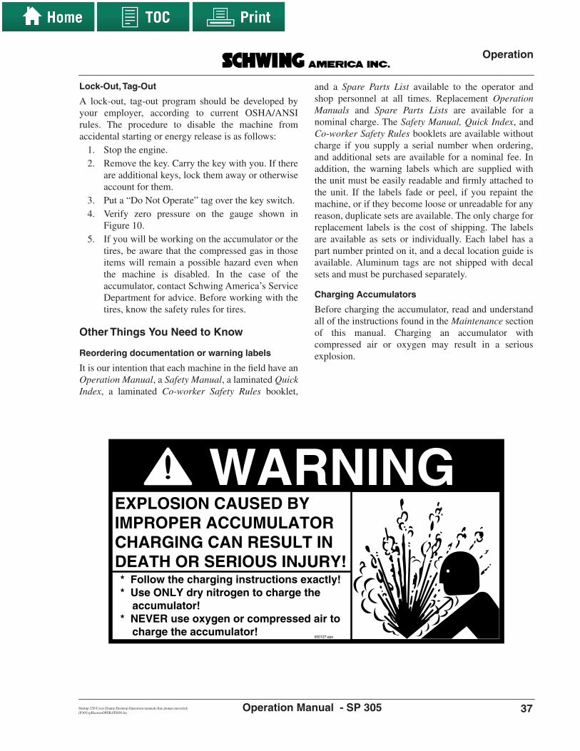
Other Things You Need to Know
Reordering documentation or warning labels
It is our intention that each machine in the field have anOperation Manual, a Safety Manual, a laminated QuickIndex, a laminated Co-worker Safety Rules booklet,
and a Spare Parts List available to the operator andshop personnel at all times. Replacement OperationManuals and Spare Parts Lists are available for anominal charge. The Safety Manual, Quick Index, andCo-worker Safety Rules booklets are available withoutcharge if you supply a serial number when ordering,and additional sets are available for a nominal fee. Inaddition, the warning labels which are supplied withthe unit must be easily readable and firmly attached tothe unit. If the labels fade or peel, if you repaint themachine, or if they become loose or unreadable for anyreason, duplicate sets are available. The only charge forreplacement labels is the cost of shipping. The labelsare available as sets or individually. Each label has apart number printed on it, and a decal location guide isavailable. Aluminum tags are not shipped with decalsets and must be purchased separately.
Charging Accumulators
Before charging the accumulator, read and understandall of the instructions found in the Maintenance sectionof this manual. Charging an accumulator withcompressed air or oxygen may result in a seriousexplosion.
WARNINGEXPLOSION CAUSED BY IMPROPER ACCUMULATOR CHARGING CAN RESULT IN DEATH OR SERIOUS INJURY!* Follow the charging instructions exactly!* Use ONLY dry nitrogen to charge the accumulator!* NEVER use oxygen or compressed air to charge the accumulator!
000127.eps

Operation
38 8/4/11Operation Manual - SP 305
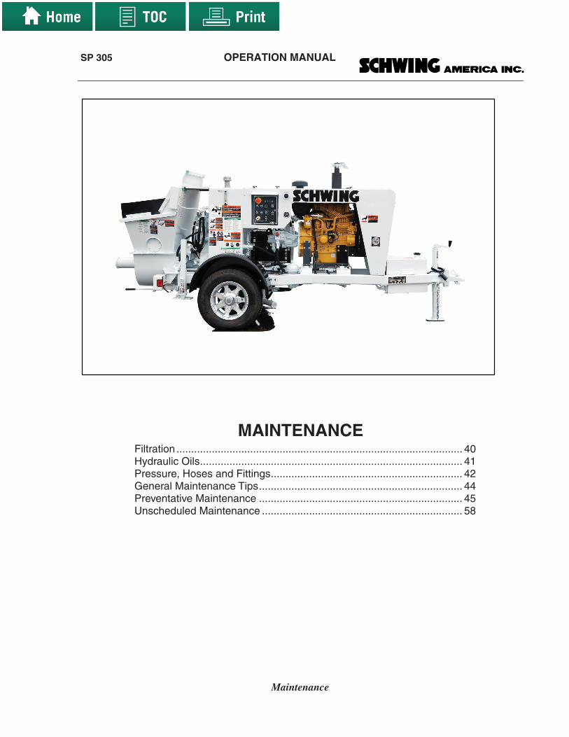
SP 305 OPERATION MANUAL
Maintenance
MAINTENANCE Filtration ................................................................................................. 40 Hydraulic Oils......................................................................................... 41 Pressure, Hoses and Fittings................................................................. 42 General Maintenance Tips..................................................................... 44 Preventative Maintenance ..................................................................... 45 Unscheduled Maintenance .................................................................... 58

Maintenance
40 8/4/11Operation Manual - SP 305
MAINTENANCEMaintenance is what you do to the machine to keep itin good working condition. There are two kinds ofmaintenance: preventative and repairs. Preventativemaintenance is important to avoid unnecessary repairs,but eventually even well maintained machine parts willwear out and require repair or replacement.
Some maintenance needs to be done by a time intervalsuch as daily, monthly, or annually. It is a good idea tomake a checklist that will tell you what maintenance isdue and when it is due. A suggested checklist isincluded in this section of this manual. It can be foundon page 57. Keep accurate records of maintenanceperformed and when the work was completed. In thisway, you will know that all necessary work has beencompleted on time. Complete maintenance recordscould also make the machine worth more money whenit comes time to sell or trade it.
There are certain things you should know about themaintenance of your machine that will not come up ona timetable of things to do.
We begin the section with some general informationregarding some of these items.
Filtration
General informationFiltration is the single most important method ofkeeping your unit’s hydraulic system operational.Particles that could damage the components areintroduced into the oil by the differential cylinders andthe valves, through the reservoir breather, and byinternal wear in the components. Additionally, whenyou change hydraulic oil, the new oil is not cleanenough to be used in a concrete pump without beingpre-filtered. In fact, new hydraulic oil is only filtered atthe refinery to 40μ (40 microns). The oil in your unitneeds to be filtered to a MINIMUM of 25μ, andpreferably finer than that. Filters are rated by:• the size of particles they trap, and whether that size
is nominal or absolute• the dirt holding capacity, in grams• the clean element pressure drop for a given flow
rate (in PSI and gallons per minute or bar and litersper minute), and
• the ratio of particles of a given size encounteredversus particles passed (referred to as the betaratio). An example of a beta ratio would be β25 =200 (pronounced beta twenty five equals twohundred). This means that for every 200 particlesof 25 microns or larger that hit the filter media, onemakes it through. A finer filter would be, forexample, β12 = 200. A courser filter examplewould be β25 = 75. For concrete pumps, mediumto fine filtration is required.
Specific informationHere are some facts regarding filtration as they relate toyour pump:• Your unit has a separate oil conditioning circuit,
which includes an oil cooler and a filter. The oil ispumped from the reservoir, through the cooler andfilter, back to the reservoir.
• As delivered from the factory, each SP 305 unit isequipped with a filter that is rated at 10 micron(shown as 10μ) absolute.
• The beta ratio is β10 = 200. In our case, the betaratio means that for every 200 particles of dirt thathit the filter media that are 10 micron or larger insize, 1 will make it through. Although we are nothappy about the one particle that is allowedthrough, we do not use finer filtration because thecomponents don’t require it. Additionally, a finerfilter would plug up with dirt too often, resulting inhigh maintenance costs to you. We have settled ona compromise that should afford long service lifeand minimum maintenance costs. Don’t be fooledby the one particle that gets through, this is a highquality element with very good trappingcharacteristics.
• The clean element pressure drop is about 3 PSI at22 gallons per minute (element only) + 2.5 PSI forthe housing, making a total of 5.5 PSI DP (drop inpressure) when the element is clean. The pressuredrop varies with the viscosity of the oil, whichmeans pressure in the filter will be high until the oilis heated to normal operating temperatures.The filter will hold 55 grams of dirt, whenoperating at a flow rate of 27 GPM (gallons perminute). The flow rate is important, because thefilter would hold more if you operated at a lowerflow rate. Good filtration is not cheap, but it willsave you thousands of dollars by preventingcomponent failure.

Maintenance
Startup 250:Users:Danny:Desktop:Operation manuals:line pumps:maverick (P305):pHseriesMAINTENANCE.fm 41Operation Manual - SP 305
• The model SP 305 is equipped with a recirculationtype of filtration system, meaning that there is apump that sucks oil from the reservoir, pumps itthrough the filter and cooler, and back to the tank.Whenever the engine is running, oil is beingfiltered. The filtration is done with a spin-on filterassembly (Figure 28). It is equipped with anintegral bypass check valve set at 30 PSI. Thebypass valve protects the filter element fromdamage, as explained below. The assembly isequipped with an anti-back-flow check valve,which prevents oil from draining out of the tankwhile you are changing the spin-on element. Thereis a dirty filter indicator to tell you when theelement is dirty. You should replace the elementwhenever the indicator enters the yellow area andthe oil is heated above 20 degrees Celsius. Undernormal circumstances, the element will needreplacement about every 6 months. The elementhas been designed to remove all particles largeenough to cause undue wear and jobsitebreakdowns (beta 10 = 200). You can keep thehydraulic system running year after year byreplacing the element when replacement is due. Donot substitute “will fit” elements in this housing.
Bypass Check valve
The filter is equipped with an integral bypass checkvalve with a 30 P.S.I. pressure-to-open rating. This iswhat it does:
When the filter is clogged with dirt and oil is having ahard time making it through, the pressure differencebetween the filter inlet and the outlet rises. Thispressure difference (commonly referred to as apressure differential) is called delta P and is shown asΔP. When the ΔP reaches 30 PSI, the check valve opensand the oil returns to the tank unfiltered. If the filter didnot have the bypass check valve, it would simply breakapart when it was clogged. That could cause the filterto fail in one of two ways:
1. All of the dirt ever trapped by the filter, plus thefilter itself, could go directly into the system.
2. Worse yet, the filter could split open and leak tothe ground, draining the reservoir, andcontaminating the environment.
Both potential problems are avoided by the bypasscheck valve.
To change the element1. Make sure the engine is shut off. Put the key in
your pocket to prevent someone else fromstarting the engine.
2. Position a pan or bucket under the filter housingto catch drips. The check valve built into thefilter, which prevents back flow, should not allowmuch leakage oil, but there will be some. Oilspills contaminate the environment.
3. Unscrew the filter element. Use an oil filterwrench, if needed.
4. Remove the spin-on element, and pour the oil outinto the catch pan. Do not reuse this oil.
5. Remove the old element and replace with a newelement. Replace the bowl and tighten accordingto the installation instructions that come with thefilter.
6. Start the engine, and check for leaks.
Hydraulic Oils
General informationHydraulic oils are rated for viscosity, heat dissipation,foaming characteristics, pour point, anti-wearadditives, anticorrosive additives, lubricating qualities,compressibility, temperature range, temperaturestability, and other functions. Although many differentbrands of oil will meet these specifications, they may
PHfilter.eps
FilterElement
Dirty FilterIndicator
Figure 28The hydraulic oil filter

Maintenance
42 8/4/11Operation Manual - SP 305
use different chemical additives packages to achievethe end result. For this reason, you should not mixdifferent brands of oil. The additive package from onebrand may be incompatible with the additive packagefrom the other, rendering both packages useless.• Recently a few manufacturers have introduced
biodegradable hydraulic oils into the market. Theseoils are based on vegetable extracts instead ofmineral extracts. They are considered safer for theenvironment in the event of a spill, although theadditive packages are not inert. One brand, MobilEAL 224-H has been accepted for use in Schwingpumps, and other brands are under considerationand testing now. The main thing that you have toremember about these oils is that they must NOTbe mixed with mineral based hydraulic oils, evenin very small amounts. If you will be pumping ajob in an environmentally sensitive location andwish to use this type of hydraulic oil, pleasecontact our service department at (651) 429-0999for instructions on making the change frommineral oil.
• Viscosity of hydraulic oil is similar in concept tothe different weights of motor oil. For example, inthe winter you may run 5W-30 in your car, while inthe summer you run 10W-40. The same is true forhydraulic systems. If you live in a climate wherethe weather is changing from extremely hotconditions to extremely cold conditions, youshould consider changing the weight of thehydraulic oil that you use by the season. TheInternational Standards Organization (ISO) hasdeveloped a method of grading hydraulic oils forviscosity. For summer in northern North America,we recommend ISO VG 46 weight oil, while in thewinter we would recommend ISO VG 32 or evenVG 22, depending on how cold it gets in your area.For southern North America and Central Americawe recommend ISO VG 46 for the winter, and ISOVG 68 or VG 100 for the summer, depending onhow hot it gets. The lower the ISO VG number, thethinner the oil is, and the lower the pour point ofthe oil is. On the other hand, the thinner the oil is,the lower the temperature will have to be before itbreaks down the lubricating film that protects yourcomponents. See the chart in the Appendix sectionof this manual for help in selecting the proper oilfor your requirements.
• The quality of the oil needed for use in a Schwingmachine is rated in the DIN system. The ratingshave to do with the chemical additive package that
is introduced into the oil. Both the DIN rating HLPand HV qualities are approved for use in ourmachines.
Specific information• All machines leave the Schwing factory filled with
Mobil DTE 25 hydraulic oil unless otherwiserequested by the customer. DTE 25 has an ISOviscosity rating of VG 46. If you want your newmachine filled with a different brand or differentviscosity oil, you should specify when ordering.
• Many other brands of oil have been approved foruse in Schwing machines, including:• Texaco Rando HD and Rando HDZ• Shell Tellus oil• BP Energol• Aral Vitam• Esso Nuto• Esso Univis• Total Azolla• Wintershall Wiolan
(The order of the list doesn’t signify anything. Any oilwhich meets the quality and viscosity standardsdescribed above can be used).
When to change your hydraulic oil• You should change your hydraulic oil at least once
per year. If you use good filters and change themwhen they are dirty, the oil will be clean, even aftera year, but the chemical additive packages that givethe oil its properties will break down with time,and no amount of filtration will bring them back.
Pressure, Hoses and Fittings
General InformationThe SP 305 concrete pump hydraulic systems run withmedium-high pressures, in the 2500 PSI range. Themaximum pressure is determined by adjustment of thepressure compensator on the main hydraulic pump.The machines are designed to operate at this pressure.Concrete pressure is just a ratio of the hydraulicpressure. The ratio of hydraulic pressure to concretepressure is the same as the ratio of the differentialhydraulic system piston area to the concrete piston cuparea.

Maintenance
Startup 250:Users:Danny:Desktop:Operation manuals:line pumps:maverick (P305):pHseriesMAINTENANCE.fm 43Operation Manual - SP 305
• If you lower the pressure at which the system runs,you can defeat the power of the system. Forexample, you ask the machine to develop 2400 PSIhydraulic pressure to push the concrete where youwant it to go. You want to replace a hydraulic hosewith a less expensive, lower pressure hose, so youlower the hydraulic pump pressure setting from2500 PSI to 1500 PSI. What is the result? Theconcrete still requires 2400 PSI to get where youwant it, but your pump can only put out oil up to1500 PSI. Now the oil that should be pushing theconcrete is instead telling the hydraulic pump tostop putting out oil. Nothing moves, and yourconcrete pump has been rendered useless by acheap hydraulic hose.
• If you raise the pressure at which the system runs,you can harm the system. Using a new example,the concrete requires that the machine develop2900 PSI hydraulic pressure to push it where youneed it. Your machine is factory set to run at amaximum of 2500 PSI, so you raise the setting ofthe pump compensator to do the job. The hydraulicpump can’t withstand 2900 PSI for more than afew minutes, and it breaks. You now have toreplace a pump before you can make another pour.
• If you leave the machine at the factoryspecification, you DO NOT harm the system. Itgives you years of dependable service. This meansyou should only use fittings and hoses that have asufficient WORKING PRESSURE to handle thesystem requirements. If you take a job that needsmore pressure than your machine has, you shouldbuy or rent a higher pressure machine.
Specific Information• Schwing uses high pressure fittings and hoses on
all circuits, even if the relief valve for that circuit isset to low or medium pressure. The fittings andhoses are rated at a minimum of 5000 PSI workingpressure, and in the case of some fittings, up to15,000 PSI. We advise against changing any circuitto lower rated hoses or fittings.
• We use metric fittings and hoses, with metricthreads on the couplings. There are four diametersizes of tubes and fittings used on this unit and fourdiameter sizes of hoses. The chart in Figure 29 tellsyou what the sizes are and what they will attach to.
• All block threads are metric or BSPP.• Instructions for setting the relief functions are
shown in the preventative maintenance section ofthis manual.
Hose Size Hose I.D.
8 8 mm
13 13 mm
16 16 mm
20 20 mm
Connectswith Fitting& Tube Size
12
16
20
25
12
16
20
25
Tube &FittingSize
8
13
16
20
Connectswith
Hose Size
Tube &FittingO.D.
12 mm
16 mm
20 mm
25 mm
Tube &Fitting
I.D.
8 mm
13 mm
16 mm
20 mm
1CO
LPho
seF
ITT
ING
.eps
Figure 29Hose, fitting and tube sizes versus
connection sizes

Maintenance
44 8/4/11Operation Manual - SP 305
General Maintenance Tips
Torque specificationsWhen performing maintenance that requires removaland replacement of bolts, it is very important to adhereto the torque specifications that apply to that bolt(Figure 30).
The graphs in Figure 30 demonstrate what happens to abolt if it is not properly torqued. The dashed linerepresents the prestress on the bolt. As the device thatuses the bolt goes through its normal functions, the boltin example “A” gets stretched and relaxed with everyduty cycle, because the bolt is prestressed under themaximum force of the cycle.
In example “B”, the prestress of the bolt has beenraised to more than the maximum force of the dutycycle, so the bolt doesn’t ever feel the cycle. In thisexample, bolt “B” would last MUCH longer than bolt“A”. The torque specifications for bolts used onSchwing equipment are found in the Appendix sectionof this manual.
Adjusting relief valvesWhile adjusting a relief valve is not normally adangerous procedure, you should remember that it hasthe potential to cause trouble. The main thing to watchout for is this: Sometimes people who don’t knowbetter will have a problem with a machine and begintroubleshooting by raising the pressure setting. Whenthat doesn’t help, they forget to lower it back down.When you check the pressure by creating a hydraulicblock, the pressure is set too high. In extreme cases,this can cause hoses or fittings to burst or othercomponent failure. To be safe, you should begin theadjustment procedure by turning the adjustment deviceto the lowest possible setting, then bring the deviceback up to the proper setting.
Removal of safety devicesSometimes you will have to remove a safety guard orother safety device in order to perform maintenance.For these situations, you must take extra care to be sureof your own safety and that of your co-workers. If youhave to put your hands, feet or any other body part intoa part of the machine that would normally be guarded,be sure that the machine is turned off and that the key isin your pocket. If there is more than one key inexistence, you should also put a “DO NOT OPERATE”sign on the controls or over the start switch.
Before restarting the machine after performingmaintenance, be sure to put away all tools, parts andsupplies, and clear the area of personnel. If yourcompany has a “lock-out, tag-out” policy in place,abide by it.
Concrete pumps are big enough to hide a man. Be sureto yell “clear” before starting the unit at any time, andallow time for response before proceeding.
Time
For
ce
A
Time
For
ce
B
TorqueForce.eps
Prestress
Prestress
duty cycles
duty cycles
Figure 30Effects of proper prestressing of a bolt

Maintenance
Startup 250:Users:Danny:Desktop:Operation manuals:line pumps:maverick (P305):pHseriesMAINTENANCE.fm 45Operation Manual - SP 305
Preventative MaintenanceNOTE!
There is a sample maintenance chart shownin this section of the manual, page 57.
Daily maintenance1. Check the levels and condition of the lubricants
and coolant in the towing truck. Follow themanufacturers recommendations for quantityand type.
2. If the towing vehicle has air brakes, bleed themoisture out of the truck air system by openingthe pet cocks located on the bottom of the airtanks. This is especially important if there is achance that the moisture will freeze.
3. Check the condition of the tires on both thetowing truck and the trailer. Do not drive the unitwith bald, cracked or damaged tires.
4. Check the level and condition of the hydraulic oil(Figure 31). Top up, if necessary, with the samebrand and type of oil. If you have a filter buggyto pump oil into the tank, use it. Replace milkylooking oil, which is a sign of watercontamination. Try to determine the source of thewater, if possible. If the oil has turned milkyquickly, like from one day to the next, then justreplacing the oil will not solve your problem, andthe new oil may be milky looking the nextmorning. If you need help with ideas of where tolook for the source of water contamination, callSchwing America’s Service Department at (651)429-0999.
5. Bleed the water out of the bottom of thehydraulic oil reservoir by opening the drain cockor faucet located at the bottom of the reservoir(Figure 32). Place a drain pan under the outlethose, open the valve, and watch the liquid as itleaves the hose. When the liquid changes fromwater to oil, close the valve. Because ofcondensation, which is aggravated by largeheating-cooling cycles, it is normal that therewill be a small amount of water in the tank everyday, but it should settle to the bottom of the tankovernight. The water that is drained should beclear, and the oil that follows it should also beclean, not milky.
6. Check the differential cylinder rod packings forwear by filling the waterbox with water abovethe level of the differential cylinder rods (if nograte is installed) or above the bolt down grates(if installed). Let it sit for a few minutes. If oilbegins to float to the top of the water, it is anindication that the rod packings are worn. (Oil islighter than water, and will float.) Don’t forget to
Figure 31The hydraulic oil level indicator
Oil LevelIndicator
OilLEV.eps tankdrain.eps
Drain cock
Figure 32The drain cock used to drain water
from the reservoir

Maintenance
46
3/1/12
Operation Manual - SP 305
let the water out after the check, especially iffreezing temperatures are expected. Failure toreplace the rod packings when they need it willresult in contaminates from the water box,including water, entering the hydraulic oil at thepackings and wearing on the rods, cylindertubes, guide bushings, pistons and the pistonrings. The material that gets worn off of theabove mentioned items also becomescontamination, accelerating the wear. Leftunchecked, this wear will totally destroy adifferential cylinder. Normally, you will be duefor new packings after 1 to 2 years.
7. Each day you should visually inspect the bolts onthe rubber rams as well as those on the S - tube.Notice if there is any play. If you see somethingsuspicious, shut off the engine, put the key in
your pocket, remove the hopper grate, andinspect with a wrench. If you find that they areloose, tighten with a torque wrench to the torquespecifications found in the
Appendix
section ofthis manual. Don’t forget to replace the hoppergrate before using the machine.
8. Grease the pivot shaft bearing and outletassembly (Figure 33). This can be done on thejob as described in the
Operation
section of thismanual.
9. Visually inspect the unit for damage or leakseach day. Repairs should be made before the unitis operated.
10. Once a day you should check your maintenancechecklist to see if any scheduled maintenance isdue.
mavzerk.eps
Zerk foroutlet assembly
Grease reliefvalve
The Grease relief valve above isdesigned to prevent over greasing
which could prevent valve movement.The decal below points out that it is
indeed a relief and not a broken zerk.If it is replaced with a grease fitting
the pressure from excess grease willprevent the valve from moving.
Zerk forpivot shaft bearing
This is a grease relief port.Do not replace with a zerk fitting.
9835
5558
INFORMATION
This is a grease relief port.Do not replace with a zerk fitting.
9835
5558
This is a grease relief port.Do not replace with a zerk fitting.
9835
5558
Figure 33Grease zerks for the outlet assembly and the pivot shaft bearing to be greased each day

Maintenance
Startup 250:Users:Danny:Desktop:Operation manuals:line pumps:maverick (P305):pHseriesMAINTENANCE.fm 47Operation Manual - SP 305
Monthly maintenanceGrease the two fittings of the crank arm lever monthly(Figure 34).
Check mounting hardware
Check the mounting hardware of the subframe, the oiltank, the pumpkit, the differential cylinders, and thematerial cylinders. Check for bolt tightness, cracks andother abnormalities.
Check hydraulic pressures
Check all hydraulic pressures. The specifications foreach circuit are shown below and on the hydraulicschematic that applies to that circuit. The schematicsare all contained in the Appendix section of thismanual. Changes in pressures may indicate trouble inone or more components and will serve as earlywarning indicators IF you check them on a regularbasis. PRESSURE SETTINGS MUST BE MADEWITH THE OIL AT NORMAL OPERATINGTEMPERATURE (40° to 60° C). To heat the oil tooperating temperature:
1. When the oil is very cold (at or below the pourpoint of your hydraulic oil), Bring engine RPMto an idle and let the engine idle until the temp.gauge on the operator’s panel reads 20°.
2. When the oil is warm (40° C on the temperaturegauge of the operator’s panel), The pressure canbe checked and assumed to be accurate.
Setting the concrete pump pressure
The concrete pump pressure is preset at the factory andshould not require adjustment. The pressure cut-off onthe hydraulic pump is set at 2500 PSI and theredundant relief is 2900 PSI. If you feel that your pumphas a pressure problem, contact the Schwing AmericaService Department at the Call Center (888-Schwing).
Clean the oil cooler fins
Spray out the coils of the optional oil cooler with ahigh velocity water nozzle or pressure washer. If youuse a pressure washer, be careful not to get so close thatyou damage the electric motor or bend the cooler fins.
Grszerk.eps
Grease Zerks
Figure 34Grease zerks on the crank arm lever
should be greased monthly

Maintenance
48 8/4/11Operation Manual - SP 305
Semiannual maintenance (every 6 months)
Change hydraulic oil for temperature reasons
Change hydraulic oil if you live in a geographicallocation where the weather changes the temperaturerange drastically. If you save the oil in clean barrelsand properly store the barrels, you can reinstall this oilwhen the weather changes back. You can use the oil fora maximum of 2 six month seasons. Contact yourhydraulic oil dealer to obtain clean barrels and theproper storage procedures. Caution! If you ignoreproper storage procedures, the oil will become socontaminated that reuse will become destructive to the
machine. If you don’t own a filter buggy for oiltransfer, consider buying one, or at least rent one forthe occasions when you change your hydraulic oil.
Checking the Accumulator
The accumulator on this unit does not store energy anddoes not require charging. The accumulator function ismore to serve as a dampener than to store energy forthe purpose of shifting the valve as accumulators in atwin circuit system do. The maximum pressure on theaccumulator for the SP 305 is 1500 PSI and shouldfunction properly for years.
WARNINGEXPLOSION CAUSED BY IMPROPER ACCUMULATOR CHARGING CAN RESULT IN DEATH OR SERIOUS INJURY!* Follow the charging instructions exactly!* Use ONLY dry nitrogen to charge the accumulator!* NEVER use oxygen or compressed air to charge the accumulator! explosion warning.eps

Maintenance
Startup 250:Users:Danny:Desktop:Operation manuals:line pumps:maverick (P305):pHseriesMAINTENANCE.fm 49Operation Manual - SP 305
Annual maintenance
Change hydraulic oil for age reasons
Change hydraulic oil if you haven’t already done itbecause of the weather. The same filling rules thatapply to adding hydraulic oil apply to filling the tankafter draining and cleaning. To change the oil:
1. The engine must be shut off. Put the key in yourpocket.
2. The oil should be cool. This is for safety reasons.Do not change oil that is above 120° F (50° C).
3. Drain the old oil into barrels or another waste oilreceptacle. The oil can be pumped out of theinspection cover on the top of the tank or drainedout of the bottom of the tank (Figure 35).
4. Once the oil is drained, clean the tank through theinspection covers using cleaning solvent and lintfree rags. DO NOT USE GASOLINE! Remove allof the silt from the bottom of the tank.
5. Close the drain, if open. Refill by pumping new oilout of the barrels with a filter cart. If no cart isavailable, rent one. REMEMBER! NEW OIL ISNOT CLEAN ENOUGH TO INSTALL IN YOURUNIT. If you ignore this step, you may beginhaving trouble with pumps and valves immediatelyor within the first few days. See the information atthe beginning of this chapter for specificinformation about hydraulic oils that are approvedfor use in Schwing machines.
6. Change the main return filter before restarting theunit (Figure 35).
Inspection cover
Filler cap
tankfill.eps
tankdrain.eps
Drain cock
PHfilter.eps
FilterElement
Dirty FilterIndicator
Figure 35Change hydraulic oil

Maintenance
50 8/4/11Operation Manual - SP 305
Check the pre- charge of accumulators
Check the accumulator gas pre-charge as shown:• 1st check-one week after first use• 2nd check-three months after first use• 3rd check-one year after first use• 4th check and beyond-annually
If the accumulator requires charging, read all of theinstructions before beginning the job. Accumulatorsmust be charged only with dry nitrogen. Never usecompressed air or oxygen (Figure 36), as the oxygenmolecules will combine with the hydraulic oil andlower the flash point of the oil to below roomtemperature. You will create a major explosion byusing compressed air or oxygen to chargeaccumulators. People have died using compressed airor oxygen to charge accumulators. Use dry nitrogen,not liquid nitrogen.
Charging procedure
The following steps are required for checking andcharging the accumulator.
1. Before you begin, you will need a charging kit(Figure 37). Do not attempt to charge theaccumulators without one. You can order thecharge valve assembly from Schwing Americausing part number 30338635. There is also a kitavailable directly from Hydac. Hydac Corporationcan be reached at (610) 264-9503. The Hydac partnumber is FPS 250 F 2.5 G4 K.
2. You must use a high-pressure regulator with thenitrogen bottle. If it was not supplied with thebottle, order one before proceeding with this job.
3. Before beginning the charging procedure, stop theengine, and remove the key.
NOTE!The accumulator on the P305 does not serveto shift the Rock Valve as it would on a twincircuit system. The only function of theaccumulator on this unit is to absorb shockfrom pressure spikes as the valve shifts.
Figure 36Warning decal for accumulator charging
WARNINGEXPLOSION CAUSED BY IMPROPER ACCUMULATOR CHARGING CAN RESULT IN DEATH OR SERIOUS INJURY!* Follow the charging instructions exactly!* Use ONLY dry nitrogen to charge the accumulator!* NEVER use oxygen or compressed air to charge the accumulator! explosion warning.eps

Maintenance
Startup 250:Users:Danny:Desktop:Operation manuals:line pumps:maverick (P305):pHseriesMAINTENANCE.fm 51Operation Manual - SP 305
Figure 37Accumulator charge kit for HYDAC
bladder accumulators
Nitrogen bottle
Hose30341207
Charge valve assembly30341201
Tankpressure
Regulatedpressure
High pressure gas regulator is not
included with the kit. These are
available from the nitrogen supplier.
Regulator adjustmenthandle
HYDAC bladderaccumulator
BPLAccumulator Charging Kit
(Includes hose and charge valve assembly)SCHWING PART NUMBER:
30338635
200
150
100
500
10001500
2000
2500
50
0 barPSI
chargekit PN's.eps

Maintenance
52 8/4/11Operation Manual - SP 305
4. Remove the valve protection cap and the valve sealcap from the accumulator that you will charge first(Figure 38).
HYDAC bladderaccumulator
Valve seal cap
Valve protection cap
Valve stemO-ring
accum closeup
Figure 38Detail of accumulator
gas valve area

Maintenance
Startup 250:Users:Danny:Desktop:Operation manuals:line pumps:maverick (P305):pHseriesMAINTENANCE.fm 53Operation Manual - SP 305
5. On the charge valve assembly, locate the T-handleof the gas chuck (Figure 39). Rotate itcounterclockwise (outward) completely beforeattaching the swivel nut to the accumulator gasvalve stem.
6. On the charge valve assembly, close the bleedvalve (Figure 40), and disconnect the hose from thegas valve stem. This step closes the charge valvestem to prevent the gas pressure from escaping outof the hose and ensures that the initial pressurereading is accurate.
Figure 39Charge valve assembly
200
150
100
500
10001500
2000
2500
50
0 barPSI
Gas chuck
Bleed valve
Pressuregauge
T-handle
Swivel nutGas
valve stem
Valve body
accu
m c
harg
e as
sy.e
ps
200
150
100
500
10001500
2000
2500
50
0 barPSI
Bleed valve
Close valve
Remove hose
char
ge a
ssy/
blee
d/ho
se.e
ps
Figure 40Close bleed valve and
disconnect hoses

Maintenance
54 8/4/11Operation Manual - SP 305
7. Find the swivel nut (Figure 41) on the charge valveassembly. Screw the swivel nut onto theaccumulator gas valve. Tighten to 10–15 in./lb.
8. After the swivel nut is attached, screw the T-handle(Figure 39) in (clockwise) three (3) full turns. Thispresses a pin into the gas valve and opens it. Readthe pressure on the charge valve assembly gauge(Figure 42) before you attach the nitrogen bottle tothe charge valve assembly. The pressure shouldread 103 bar (1500 PSI). If there is no reading onthe gauge, turn the T-handle in (clockwise) onemore full turn.
NOTE!If the T-handle is turned in (clockwise) morethan 4 full turns from the fullcounterclockwise position, it may damagethe accumulator gas valve.
• If no adjustment is necessary, skip to step #16.• If pressure is too high, skip to step #13.• If pressure must be added, proceed to step #9.
.
Figure 41Attach swivel nut to
accumulator gas valve
200
150
100
500
10001500
2000
2500
50
0 barPSI
HYDAC bladderaccumulator
Swivel nut
Valve stem
charge assy/ontoaccum.eps
Figure 42Read nitrogen pressure
on gauge
200
150
100
500
10001500
2000
2500
50
0 barPSI
Spec. 100 bar (1450 PSI)
read gauge.eps

Maintenance
Startup 250:Users:Danny:Desktop:Operation manuals:line pumps:maverick (P305):pHseriesMAINTENANCE.fm 55Operation Manual - SP 305
9. Be sure that the nitrogen bottle supply valve isfirmly closed. Attach the high-pressure regulator tothe nitrogen bottle; then attach the hose to the high-pressure regulator. Finally, attach the other end ofthe hose to the valve assembly gas valve stem, asshown in Figure 43. Do not open the nitrogenbottle supply valve yet.
10. Turn the regulated pressure adjustment handle onthe high-pressure regulator counterclockwise to itsminimum setting.
11. Crack open the nitrogen bottle supply valve(Figure 44). You will get a reading on the high-pressure gauge side of the regulator. Note that ifthere is not at least 1500 PSI showing on the highpressure regulator gauge at this time, you will notbe able to charge the nitrogen to the 1500 PSIspecification. If that is the case, you will need anew bottle of nitrogen before proceeding. If thereis enough pressure in the nitrogen bottle to do thejob, proceed to step #14.
12. Adjust the regulator handle clockwise, raising theregulated pressure. The accumulator will begin tofill. Continue filling until the charge kit gaugereads the desired pressure of 1500 PSI. Close thenitrogen bottle supply valve.
13. If you overcharge the nitrogen pressure, proceed asfollows:• Close the nitrogen bottle supply valve.• Slowly open the bleed valve on the charge kit.
Close the bleed valve when the correctpressure is reached.
NOTE!Never let nitrogen out of the accumulator bypressing the gas valve pin with a foreignobject. The high pressure may rupture thevalve seat!
14. Let the nitrogen sit in the accumulator for 10 to 15minutes. This allows the gas temperature tostabilize. Recheck the pressure on the charge kitgauge.
Nitrogen bottle
High-pressureregulator
Regulated pressureadjustment handle
Nitrogen supplyvalve
Bleed valve
Higher
Lower
200
150
100
500
10001500
2000
2500
50
0 barPSI
chargekithookup
Figure 43Make connections
between nitrogen bottle and
charge kit

Maintenance
56 8/4/11Operation Manual - SP 305
15. Add or release nitrogen until the pressure iscorrect. Be sure that the bleed valve is closedbefore adding pressure and that the nitrogen bottlesupply valve is closed before releasing pressure.
16. When the correct pressure is reached, proceed asfollows:• Close the nitrogen bottle supply valve.• Unscrew the T-handle on the charge kit
(counterclockwise) until resistance is felt. Thiswill close the accumulator gas valve.
• Open the bleed valve, which releases thepressure in the hose, charge valve assembly,and regulator.
• While holding the gas valve on theaccumulator, unscrew the charge kit swivelnut.
• Remove the charge kit.• If you are finished with the charge kit, remove
the hose and regulator.
17. Make a bubbly mixture from soap and water.Spread the mixture around the accumulator gasvalve to check for gas leaks. Gas leaks will pushthe bubbles away from the area of the leak. If youfind a leak, replace the accumulator or have itrepaired by qualified personnel. Never repair anaccumulator yourself.
18. Replace the gas valve seal cap (tighten to 22 ft./lb.), and hand-tighten the valve protection cap.
19. Repeat the procedure for any other accumulators.
Figure 44When the supply
valve is open, bottle pressure shows on the high pressure
gauge
MUST read at least 1500 PSI
Nitrogen Bottle
Crack open supply valve
mavCracksupply.eps
WARNINGEXPLOSION CAUSED BY IMPROPER ACCUMULATOR CHARGING CAN RESULT IN DEATH OR SERIOUS INJURY!* Follow the charging instructions exactly!* Use ONLY dry nitrogen to charge the accumulator!* NEVER use oxygen or compressed air to charge the accumulator! explosion warning.eps

Maintenance
Startup 250:Users:Danny:Desktop:Operation manuals:line pumps:maverick (P305):pHseriesMAINTENANCE.fm 57Operation Manual - SP 305
Scheduled maintenance checklistThe following is the normal recommendedmaintenance schedules (after the break-in period).
SCHEDULED MAINTENANCE
Item D W M S A A page:
Change main return filter When plugged....... .................................................40Check tires X .............................................................................45Check hydraulic fluid X .............................................................................45Bleed moisture from hyd. tank X.............................................................................45Check differential cyl. rod packings X.............................................................................45Inspect bolts on rock valve & rams X.............................................................................46Grease rock & agitator bearings X.............................................................................46Fill optional auto greaser reservoir X .............................................................................46Inspect for damage and leaks X.............................................................................46Check if maintenance is due X.............................................................................46Inspect cutting ring & rotate, if needed ........ X ...................................................................58
Check unit mounting hardware .................. X..........................................................47Check hydraulic pressures .................. X..........................................................47
Change oil for temperature reasons ..............................X ...............................................48Charging the accumulator ..............................X ...............................................48
Change oil for age reasons ..........................................X...................................49
D = daily, W = weekly, M = monthly, SA = semi annually, A = annually

Maintenance
58 8/4/11Operation Manual - SP 305
Unscheduled MaintenanceThe following items will have to be maintained on yourpump. The time of service that you get from these partsvaries dramatically from unit to unit because of thewide range of applications to which these machines aresubjected. Differences in concrete and pressure play amajor role in the wear of these components.
Wear partsThe cutting ring on this unit will wear with yardspumped. The gap between the cutting ring andtransition tube (Figure 45, top) is designed to be 1/8thof an inch. The gap can be monitored and kept intolerance by turning the adjusting nut on the slew lever(Figure 45, bottom) with the 3 1/4” wrench that issupplied or with a channel lock pliers. After theadjusting nut is tightened all the way, the cutting ringshould be changed. Failure to maintain the 1/8th inchgap will cause premature wear of the cutting ring andspec. plate.
Changing ramsWhen you begin to see grout in your waterbox at theend of the day, it is time to change the rams.
NOTE!When changing rams, you will have to putyour hands in the material cylinder onseveral occasions. YOU MUST TAKE THEFOLLOWING PRECAUTIONS TO AVOIDAMPUTATION OF HANDS, ARMS ANDFINGERS:
• DO NOT REACH INTO THE MATERIALCYLINDER WITH THE ENGINE RUNNING.
• DO NOT USE THE REMOTE CONTROLFOR THIS PROCEDURE! UNPLUG IT ANDSTORE IT.
• DO NOT ALLOW ANYONE ELSE NEAR THECONTROLS WHEN YOU ARE CHANGINGRAMS. The chances of accidental amputation aregreatly increased if more than one person isaround. There are also less distractions when youare alone, so your attention will not becomedivided. If someone comes up, stop working untilthey leave.
• Please do not skip any of the above steps.
To remove the old rams
1. Start the engine.
2. Close the shut-off valve (also known as the ballcock and quarter turn valve Figure 46).
3. Drain the waterbox.���������
��� �������������� ���
������� ���� �
������������ ����
Figure 45Cutting ring gap (top)
Adjustment nut for cutting ring (bottom)
305clsd.eps
Figure 46Concrete pump shut-off valve

Maintenance
Startup 250:Users:Danny:Desktop:Operation manuals:line pumps:maverick (P305):pHseriesMAINTENANCE.fm 59Operation Manual - SP 305
4. Activate the pump in reverse mode, bringing thepiston cup down to the end of the material cylinder.The pump will pressure out before the S-tubeshifts, because the shutoff valve is closed; however,you should be able to stop the pump and haveaccess to the piston cup before the pump pressuresout.
5. Push the emergency stop button on the operator’spanel and stop the engine. Put the key in yourpocket, and verify that the pressure gauge isshowing zero.
6. Remove the hopper on the SP 305 by removing allof the hopper mount bolts.
7. Place a 1 1/8” socket on an impact wrench, andremove the center mount bolt (Figure 47).
8. Remove the piston cup assembly from the materialcylinder.
NOTE!If the cup won’t slide out easily: start theengine, release the e-stop, and activate thepump in forward mode just long enough topull the rod away from the piston cup. Stopthe pump before the cylinder reaches theend of the stroke, push the e-stop button,stop the engine, and put the key back inyour pocket.After verifying zero pressure on the gauge,use a screwdriver or small pry tool in thecenter bolt hole to remove the piston cup.
9. Separate the components (Figure 48), and clean allresidue from the face plate and O-ring back plate,as well as the O-ring groove.
10. Install the new O-ring on the back plate, and applya coat of grease to the entire O-ring.
To install the new ram
1. Start the engine and run the piston rod back downto the end of the stroke, stop the engine, push the e-stop button, and put the key in your pocket.
NOTE!An alignment/installation tool is suppliedfor installing the new ram. If the alignmenttool is lost, it may be helpful to cut the headfrom a 3/4” bolt that is 3 to 4 inches long,screw the alignment bolt into the end of therod, and slide the components over the boltto reinstall.
2. The back side of the O-ring back plate is keyed forthe purpose of rod alignment. This keyway, or pilothole, should also be greased lightly before beingplaced on the alignment pin.
3. Push the back plate into the material cylinder, andalign the pilot with the end of the rod.
4. Grease the new piston cup, and slide it over thealignment pin with the flat side to the back plate, asshown in Figure 48.
�����������
���� ��� ���� � ����
������ ��� ����� ������
Figure 47Piston cup mount bolt should be removed
with an impact wrench
cupparts.eps
Back Plate
Piston cupFace Plate
Installation tool
Figure 48Piston cup components

Maintenance
60 8/4/11Operation Manual - SP 305
5. Set up the face plate as follows:• 3/4” bolt• Lock washer• Faceplate w/chamfer opposite bolt head• O-ring• Bushing w/chamfer facing back• O-ring
6. Coat threads of center bolt with Never Sieze.
7. Remove the alignment bolt and replace it with the3/4” center bolt and face plate.
8. Tighten the 3/4” bolt until tight.
9. Open the shutoff valve. (Note that the unit will notcycle with this valve closed.) Repeat procedure forthe other side.
Changing the material cylinders
The material cylinders also eventually wear out. Theyare considered worn out when the inside diameter hasgrown 3 millimeters beyond the specification for new.For example, a 750-18 has 180mm material cylinders.When the inside diameter reaches 183 mm, they areworn out. With 150’s they are worn out at 153, etc.Normally, it is the end attached to the valve that wearsout first, because it sees the most concrete. Thewaterbox end may be in brand new condition, becausethat end never experiences concrete. For this reason,the material cylinders were designed to be able to flipthem end-for-end. That way you can move the wornout part to the waterbox and the like-new part to theconcrete valve for double the life. If you are going todo this, you have to catch the wear on the materialcylinders before they get too thin or break through inone or more spots. When that happens you can’t flipthem, because they would be structurally too weak tohold the pressure forces at the waterbox end.
The actual act of changing and aligning the materialcylinders was the subject of a service bulletin in 1986.The procedure still applies today. Contact Schwing’sService Department at (651) 429-0999 if you need acopy of the bulletin.
Inspecting hydraulic hoses
Hydraulic hoses should be checked during routineinspections. Check for damage to the outer layer orfittings. For example; Wire reinforcement is exposed,separation from the fitting, chafing, cuts, cracks, brittleouter layer or any other type of deformation like layerseparation, blistering, crushing, corrosion, or kinking.In addition check for leaking fittings or improper fit.
NOTE!Hydraulic hoses should be replaced every sixyears to avoid the possibility of accidentalrupture and possible personal injury. Thedate of manufacture of a hydraulic hose canbe found stamped into the hose fitting.

SP 305 OPERATION MANUAL
Appendix
APPENDIX Hydraulic Oil Viscosity Chart ................................................................. 62 Torque Specifications for SAE Bolts ...................................................... 63 Recommended Emergency Hose Kit..................................................... 64 Fitting Wrench Sizes.............................................................................. 64 Maintenance Checklist........................................................................... 66 Weld-on Ends / Coupling Comparison................................................... 67 Output Charts ........................................................................................ 68 Using a Nomograph............................................................................... 74 Minimum Pipe Wall Thickness ............................................................... 82 Pictograms............................................................................................. 83 Decal Location Guide ............................................................................ 84 Glossary of Terms.................................................................................. 86 List of Lubricants and Nitrogen.............................................................. 91 Hydraulic Schematic—Concrete Pump SP305 - Schematic.................. 95 Hydraulic Schematic—Concrete Pump SP305 - Schematic.................. 95 Electrical Schematic SP305 - 2004 Electric .......................................... 96 Electrical Schematic SP305 - 2004 Electric .......................................... 96 Output Chart available upon request ..................................................... 99

Appendix
Operation Manual - SP 30562 revDate
APPENDIXThis section contains the technical information foryour machine and its systems. This information iscorrect for your machine when it leaves the factory, butit may need to be updated from time to time.
Hydraulic Oil Viscosity ChartThe illustration below shows the relationship betweenthe oil temperature and its viscosity. As you can see,the oil gets thicker when the temperature is low andthinner as the temperature rises.
• The cold start limit represents the coldest tem-perature at which the oil is thin enough to flowinto the hydraulic pumps. If it were any colder,the pumps would not be able to suck in the oil(cavitation).
• The minimum permissible viscosity representsthe warmest temperature at which the oil willstill be thick enough to provide lubrication andsealing. If it were warmer, the componentswould have metal-to-metal contact (thermalbreakdown).
• The optimum operating viscosity is the rangeof oil thickness at which the oil works best(thin enough to flow easily, yet thick enough toprotect the system components).
An example of how to read a chart for VG-46 oil isgiven in the chart below. The chart shows the cold startlimit as –8°C (18°F) and the minimum permissibleviscosity as 90°C (194°F). The optimum range is 50°–76°C.
-40 -30 -20 -10 0 10 20 30 40 50 60 70 80 90 100 110 120
-40 -30 -20 -10 0 10 20 30 40 50 60 70 80 90 100 110 120
Temperature of Hydraulic Oil
-40 -22 -4 14 32 50 68 86 104 122 140 158 176 194 212 230 248
(C)
(C)(F)
C = degrees CelsiusF = degrees Fahrenheit
Wat
er fr
eeze
s
Wat
er b
oils
Cold Start Limit(very thick oil)
Minimum permissibleviscosity
OptimumOperatingViscosity
VG 22VG 32VG 46VG 68VG 100
0000
44.e
ps

Appendix
SP 305Startup 250:Users:Danny:Desktop:Operation manuals:line pumps:maverick (P305):Appendix.fm Operation Manual - 63
Torque Specifications for SAE BoltsThe following charts show the tightening torquesspecified for the bolts used on PH series pumps. Thecharts are to be followed unless a different torquespecification is indicated for a particular procedure.
A torque wrench must be calibrated to within 1% of itsindicated value throughout its range. Bolts must betorqued to within 4% of the requirement if the wrenchhas a dial scale. If no dial scale is present, the bolts
must be torqued to within 6% of the requirement. Forexample, a bolt to be torqued to a 200 poundrequirement must be within the range of 208–192 footpounds for a dial scale torque wrench.
Schwing equipment uses two different types of bolts;one has a black finish and the other has a dychromatefinish.
Torque specifications are very important for propermachine function. For more information on thissubject, refer to the section on bolt tightening in theMaintenance section of this manual.
GENERAL SAE BOLT TORQUE SPECIFICATION TABLEUse the values listed unless special torques are specified. Values are for UNC and UNF thread fasteners.
Values do not apply if graphite, moly-disulphide or other extreme pressure lubricant is used.Table 1
SAE Grade Number
5 8
Bolt head identifi-cation marks. See Note below.
Bolt Size lb.-ft N•m lb.-ft N•m
1/4” 9-11 12-15 12-15 16-20
5/16” 17-20.5 23-28 24-29 33-39
3/8” 35-42 48-57 45-54 61-73
7/16” 54-64 73-87 70-84 95-114
1/2” 80-96 109-130 110-132 149-179
9/16” 110-132 149-179 160-192 217-260
5/8” 150-180 203-244 220-264 298-358
3/4” 270-324 366-439 380-456 515-618
7/8” 400-480 542-651 600-720 814-976
1” 580-696 787-944 900-1080 1220-1464
1-1/8” 800-880 1085-1193 1280-1440 1736-1953
1-1/4” 1120-1240 1519-1681 1820-2000 2468-2712
1-3/8” 1460-1680 1980-2278 2380-2720 3227-3688
1-1/2” 1940-2200 2631-2983 3160-3560 4285-4827
NOTE: Bolt head identification marks are shown as per grade. Manufacturer’s marks may vary.

Appendix
Operation Manual - SP 30564 revDate
Recommended Emergency Hose KitSchwing recommends that you carry one of each of thefollowing hoses on the unit in case you blow a hose onthe job. Each size listed represents the longest hose ofeach diameter that is installed on the unit at the factory.Keep the insides of the hoses clean until they areneeded by capping the ends and using tape to hold thecap in place. Dirt introduced into your hydraulicsystem through the installation of a hose that was notkept clean will cause a variety of problems in theoperation of the unit.
Fitting Wrench SizesThis chart is provided as an aid to selecting the properwrench to hold or tighten the hydraulic fittings onSchwing equipment. Sizes may change, so use thischart only as a guide.
�������� ���� ���� ������
��������
������
�� �����
������������
����������������
��������
��
��
��
�
����� � ���� ����
����
�����
��� ���
����
�����
������ ���
����
!�
!�
��
�"
��� ���
����
!�
�"
�#
�"
������ ���
����
"�� !�$
� !���
� "��� � ��$
� ����
%�� �& ' �&( ����) ��� �)� *�� �&� ' �&( ����)
%�+,����)���)
Straight fittings

Appendix
SP 305Startup 250:Users:Danny:Desktop:Operation manuals:line pumps:maverick (P305):Appendix.fm Operation Manual - 65
�� ��
�� ��
�� � ��� ��
��
����� ��
���� ������ ��� ������� ���
!���" #���"$ ���% �����%� &���"�� #���"$ ���%
'�� ��� ��� ��� ������� ��� '�� ���
�� � �(� ��
�� � ���� ��
����� (�
(�
(�
��
�)
�
(�
��
��
)� (�
� (���
� )��� � ��
� ����
(�
�)
�*
�* )�
)�
� +�
� ��
�� �) )� )� �� � ����
�� (� )� �+���� � (���
�
(�
�
(� � (��� � ����
� �(��� � +� �
�) � (���
� �(����+ ��
�� ��
�� � �(� �� �� � )� )� �� �+���
End Cap Separate from Stem
End Cap Part of Stem
��,���-����%
.��/ .��/ .��/ .��/ .��/ .��/
Banjo fittings

Appendix
Operation Manual - SP 30566 revDate
Maintenance ChecklistThe following are the normal recommendedmaintenance schedules (after the specified break-inperiod).
SCHEDULED MAINTENANCE
Item D W M S A A page:
Change main return filter When plugged ...... .................................................40Check tires X.............................................................................45Check hydraulic fluid X.............................................................................45Bleed moisture from hyd. tank X.............................................................................45Check differential cyl. rod packings X.............................................................................45Inspect bolts on rock valve & rams X.............................................................................46Grease pivot shaft and bearings X.............................................................................46Fill optional auto greaser reservoir X.............................................................................46Inspect for damage and leaks X.............................................................................46Check if maintenance is due X.............................................................................46Inspect cutting ring & rotate, if needed ........ X ...................................................................58
Check unit mounting hardware .................. X .........................................................47Check hydraulic pressures .................. X .........................................................47
Change oil for temp. reasons ..............................X ...............................................48Checking the accumulator ..............................X ...............................................48
Change oil for age reasons ..........................................X...................................49
D = daily, W = weekly, M = monthly, SA = semi annually, A = annually

Appendix
SP 305Startup 250:Users:Danny:Desktop:Operation manuals:line pumps:maverick (P305):Appendix.fm Operation Manual - 67
Weld-on Ends / Coupling Comparison
Heavy Duty
Metric
Grooved(Victaulic)
Male / FemaleO-Ring(shown with clamp)
weldends4.eps
0.15"
NOTE: All pressure ratings listed refer to 5 inch (125mm) diameters in like-new condition. Other pressures would apply to other sizes.
3. Metric couplings are designed for pressures up to1400 PSI @ 2:1. They have 85% more contact areathan grooved couplings. The face is flat and will notdraw pipe together. Although they have a raisededge, they are not compatible with Heavy Duty cou-plings unless a special clamp or an adapter pipe isused to change from one style to the other. Metricconnections are standard equipment on boomsbecause of the weight savings compared with otherstyles.
2. Heavy-Duty couplings are designed for pressuresup to 2250 PSI @ 2:1. They have 20% more contactarea than metric couplings, and a tapered face thatdraws the pipe sections together during assembly.Both the ends and clamps weigh more than metricstyle, and therefore should not be used on boomswithout consulting the manufacturer.
1. Male / female o-ring type couplings have thehighest pressure rating of the ends commonly usedfor concrete pumping. They can withstand 4350 PSI@ a 2:1 safety factor. They are self aligning andwaterproof when used with o-rings in good condi-tion. Typically not used on booms because of theirweight. Pipes equipped with this style couplingcannot be swapped end-for-end.
4. Grooved couplings (lip height of 0.15” or less)are designed for pressures only up to 750 PSI @2:1. The recessed groove is hard to clean whenchanging pipe on a job. The weld-on end failsbefore the pipe because the groove is cut into thepipe thickness, making it the weakest spot. Groovedcouplings are not recommended for concrete pump-ing applications.
Shown is a comparison among commonly usedends/couplings. No two ends shown can be joinedwithout the use of an adapter pipe or a specialadapter clamp. Clamps and pipe strength must alsobe considered when determining proper systemrequirements. The ratios shown in the text belowrepresent the safety factor from burst : workingpressures.

Appendix
Operation Manual - SP 30568 revDate
Output ChartsThe hydraulic pumps that drive your concrete pump arehorsepower controlled. That means that when pressurerises past a certain point (known as the breakpoint), thepumps change their displacement per revolution,resulting in less flow and fewer strokes per minute. Thereason for this is so the pumps will not stall yourengine by drawing too much horsepower. Output chartsshow the horsepower curve (in kilowatts, or Kw) of theconcrete pump hydraulic circuit. From them, you candetermine the:
• maximum concrete pressure of the pumpkitmodel,
• maximum output (in cubic yards per hour) ofthe pumpkit model,
• maximum strokes per minute of your pumpkitmodel,
• maximum output (in liters per minute, L/min)of your hydraulic pumps,
• output that can be expected at various pumpingpressures,
• condition of your hydraulic pumps when usedin conjunction with a flowmeter, and
• breakpoint of your hydraulic system.
An explanation of an output chart is shown on thefollowing pages, followed by some examples of chartusage. The output chart of the pumpkit shipped withthis manual is shown later.
Using the chart
Rev. 081997
Init.
SAIE 5240-032
BPL 1200 HDR-23 - SP
230mm x 2000 mm
CONCRETE OUTPUTNUMBER OF STROKES
(stroke / min.)
OIL VOLUME(liter / min.)
NUMBER OF STROKES(stroke / min.)
OIL VOLUME(liter / min.)
117
ROD SIDE
Hydraulic relief valve is set at350 bar max. pressure (5075 PSI).
Pump Speed1900 RPM
Performance characteristics ofthe axial piston hydraulic pump
130 mm / 80 mm x 2000 mm 2 x Voac V30D 1402 x 92 KW
Differential Hydraulic CylinderBore dia. / Rod dia. x Stroke length
Hydraulic PumpsType / KW
Material CylindersBore dia. x Stroke length
PISTON SIDE
PISTONSIDE
RODSIDE
5 10 15 20 25
5 10 15 20 25 3028.5
17.8
350100 200 300 40050 150 250 500450
PIS
TO
N S
IDE
(bar
)
RO
D S
IDE
(bar
)
1621
1007
OIL
PR
ES
SU
RE
350
50
100
150
200
250
300
50
100
150
200
250
300
350
30
187
Slewing cylinder 80 / 45 x 185
100 200 300 400 500
PSI
100
200
300
400
500
600
700
800
900
1000
1100
1200
1300
1400
1500
1600
1700
1800
1900
2000Bar
7
14
21
28
34
41
48
55
62
69
76
83
90
97
103
110
117
124
131
138
cu yards/ hr
7 15 23 30 38 46 53 61 69 76 84 92 99 107 115 122 130 138 145 153 cu meters/ hr
20 40 60 80 100 120 140 160 180 200
concrete pressure
0
THE PERFORMANCE CURVE INDICATES THAT THERE IS NO ALLOWANCE FORFILLING EFFICIENCY OF THE CONCRETE CYLINDER.
Breakpoint=199 bar
Min Q@ 350 bar=284 l/m
Concretepressure isshown here.Max. pressureis shown forboth pistonand rod sideconfigurations.
Concreteoutput isshown here,with max.shown for bothpiston and rod sideconfigurations.
Informationabout thepumpkit andhydraulicpumps isshown here.
Hydraulic liters perminute, and thecorrespondingstrokes per minute,for both piston androd side.
The breakpoint
specification arelisted here.
and minimum Q
The Schwing ISO
and revision date are listed here.
document number
000026.eps
Hydraulic oilpressure shownhere, ranging fromzero to the reliefvalve setting.
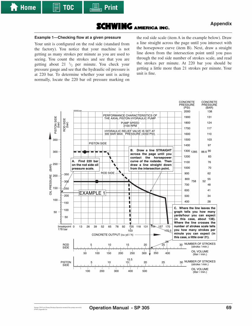
Appendix
SP 305Startup 250:Users:Danny:Desktop:Operation manuals:line pumps:maverick (P305):Appendix.fm Operation Manual - 69
Example 1—Checking flow at a given pressure
Your unit is configured on the rod side (standard fromthe factory). You notice that your machine is notgetting as many strokes per minute as you are used toseeing. You count the strokes and see that you aregetting about 21 1/2 per minute. You check yourpressure gauge and see that the hydraulic oil pressure isat 220 bar. To determine whether your unit is actingnormally, locate the 220 bar oil pressure marking on
the rod side scale (item A in the example below). Drawa line straight across the page until you intersect withthe horsepower curve (item B). Next, draw a straightline down from the intersection point until you passthrough the rod side number of strokes scale, and readthe strokes per minute. At 220 bar you should begetting a little more than 21 strokes per minute. Yourunit is fine.
13
CONCRETE OUTPUT (cu yd / h)
NUMBER OF STROKES(stroke / min.)
OIL VOLUME(liter / min.)
NUMBER OF STROKES(stroke / min.)
OIL VOLUME(liter / min.)
26 39 52 65 78 92 105 118 131 1440103
157 170 183
ROD SIDE
HYDRAULIC RELIEF VALVE IS SET AT300 BAR MAX. PRESSURE (4350 PSI).
PUMP SPEED2100 RPM
PERFORMANCE CHARACTERISTICS OFTHE AXIAL PISTON HYDRAULIC PUMP
PISTON SIDE
PISTONSIDE
RODSIDE
100 200 300 400
350100 200 300 40050 150 250
500
5 10 15 20 25
5 10 15 20 25 30
15.5
PIS
TO
N S
IDE
(bar
)
RO
D S
IDE
(bar
)
CONCRETEPRESSURE
(BAR)
7
14
21
28
34
41
48
55
62
70
76
83
90
97
103
110
117
124
131
138
CONCRETEPRESSURE
(PSI)
100
200
300
400
500
600
700
800
900
1000
1100
1200
1300
1400
1500
1600
1700
1800
1900
2000
1285 88.6
52758
350
50
100
150
200
250
300
50
100
150
200
250
300
350
OIL
PR
ES
SU
RE
(BA
R)
30
196170.5
26
EXAMPLE 1
C. Where the line leaves the graph tells you how many yards/hour you can expect (in this case, about 138). Where the line crosses the number of strokes scale tells you how many strokes per minute you can expect (in this case, a little over 21).
B. Draw a line STRAIGHT across the page until you contact the horsepower curve of the rodside. Then draw a line straight down from the intersection point.
A. Find 220 bar on the rod side oil pressure scale.
breakpoint178 bar
000025.eps

Appendix
Operation Manual - SP 30570 revDate
Example 2—Checking your hydraulic pumps
To determine whether your pumps are still in goodworking condition, use the output chart and a flowmeter. Test one pump at a time, multiply the readingsby 2, and chart the result. You must multiply thereadings because the chart is based on the output oftwo pumps, but we are only testing one at a time.
To test your pumps:• Be sure you are using the chart that applies to
your unit.• Select the proper gear for pumping (found on
the information plate mounted in the cab). • Set the pump speed (input drive shaft) RPM.
Pump speed information is found on line 16 ofthe Delivery Inspection Report which arrivedwith your unit when it was new. A differenceof even a few RPM will give you a bad read-ing. Check the RPM of the drive shaft with a
digital tachometer if one is available. • Know how to use your flowmeter. Read the
instructions that came with it, and rememberthat a flowmeter must be calibrated periodi-cally.
• Make two copies of the output chart so youdon’t ruin your original. You need one chart foreach pump tested.
Read the flow at 0 bar, 100 bar, 150 or 200 bar, 250 bar,and 300 bar. Also, document the breakpoint. Thebreakpoint is where the flow drops off rapidly. You willbe able to notice it on the flowmeter. If you think itwould be helpful, copy the chart below. Check whichreading you used (150 or 200 bar). The breakpoint willbe very close to either 150 or 200 bar, so it is notnecessary to take both readings. The breakpointspecification is shown on each output chart.
As an example, we’ll assume that we have just takenthe following readings:
Liters/min(read on meter)
Total(for plotting)
0 bar
100 bar
breakpoint
150 or 200 bar
250 bar
300 bar
x 2
x 2
x 2
x 2
x 2
x 2
Liters/min(read on meter)
Total(for plotting)
x 2
x 2
x 2
x 2
x 2
x 2
1st Pump 2nd PumpBreakpointspecification
breakpoint
000032.eps
Liters/min(read on meter)
Total(for plotting)
0 bar
100 bar
breakpoint
150 or 200 bar
250 bar
300 bar
x 2
x 2
x 2
x 2
x 2
x 2
Liters/min(read on meter)
Total(for plotting)
x 2
x 2
x 2
x 2
x 2
x 2
1st Pump 2nd PumpBreakpointspecification
breakpoint
199196194169138117
178
398392388338276234
178
000031.eps

Appendix
SP 305Startup 250:Users:Danny:Desktop:Operation manuals:line pumps:maverick (P305):Appendix.fm Operation Manual - 71
Now plot the readings on the output chart. Take a cleanoutput chart and proceed as follows:
• Lay a straight edge horizontally across thepage at the pressure point you are plotting.Draw a light line across the chart. In the exam-ple below, we use the rod side scales and curve(you could use the piston side scale and curveinstead). The ruler is shown ready to draw aline at 250 bar hydraulic pressure.
• Turn the ruler vertically, and draw a light lineup the page from the liters/minute reading youtook at that pressure (remember to multiply thereading by 2). In our example, we measured276 liters at 250 bar.
• Put a dot at the point where the two lines inter-sect.
• Do the same thing with each pressure reading.You should end up with six dots.
13
CONCRETE OUTPUT (cu yd / h)
NUMBER OF STROKES(stroke / min.)
OIL VOLUME(liter / min.)
NUMBER OF STROKES(stroke / min.)
OIL VOLUME(liter / min.)
26 39 52 65 78 92 105 118 131 1440103
157 170 183
ROD SIDE
HYDRAULIC RELIEF VALVE IS SET AT300 BAR MAX. PRESSURE (4350 PSI).
PUMP SPEED2100 RPM
PERFORMANCE CHARACTERISTICS OFTHE AXIAL PISTON HYDRAULIC PUMP
PISTON SIDE
PISTONSIDE
RODSIDE
100 200 300 400
350100 200 300 40050 150 250
500
5 10 15 20 25
5 10 15 20 25 30
15.5
PIS
TO
N S
IDE
(bar
)
RO
D S
IDE
(bar
)
CONCRETEPRESSURE
(BAR)
7
14
21
28
34
41
48
55
62
70
76
83
90
97
103
110
117
124
131
138
CONCRETEPRESSURE
(PSI)
100
200
300
400
500
600
700
800
900
1000
1100
1200
1300
1400
1500
1600
1700
1800
1900
2000
1285 88.6
52758
350
50
100
150
200
250
300
50
100
150
200
250
300
350
OIL
PR
ES
SU
RE
(BA
R)
30
196170.5
26
breakpoint178 bar
1 2 3 4 5 6 7 8 9 10 11
000454.eps

Appendix
Operation Manual - SP 30572 revDate
• Connect the dots. If your plotted line reason-ably matches the specification plot on thechart, the pump is fine. If your line is to thelower left of the specification plot, the pump isgetting weak. If your line is to the upper right,you have done the test incorrectly, or you areusing the wrong chart. In our example, thepump is okay. (See the plot that follows.)
Check the second pump. Hook up the flowmeter just aswhen you checked the first pump. Again, be sure thatyou have the correct speed, gear, chart, and so on. Thistime our example will have worse results.
13
CONCRETE OUTPUT (cu yd / h)
NUMBER OF STROKES(stroke / min.)
OIL VOLUME(liter / min.)
26 39 52 65 78 92 105 118 131 1440 157 170 183
ROD SIDE
RODSIDE
350100 200 300 40050 150 250
5 10 15 20 25 30
RO
D S
IDE
(bar
)
CONCRETEPRESSURE
(BAR)
7
14
21
28
34
41
48
55
62
70
76
83
CONCRETEPRESSURE
(PSI)
100
200
300
400
500
600
700
800
900
1000
1100
1200
52758
50
100
150
200
250
300
350
OIL
PR
ES
SU
RE
(BA
R)
196170.5
26
Breakpoint
breakpoint178 bar
250 bar
300 bar
0 bar
100 bar
200 bar
(234) (276) (338) (388)(392)
(398)
OK
Piston side scales have been removed for clarity000317.eps
Liters/min(read on meter)
Total(for plotting)
0 bar
100 bar
breakpoint
150 or 200 bar
250 bar
300 bar
x 2
x 2
x 2
x 2
x 2
x 2
Liters/min(read on meter)
Total(for plotting)
x 2
x 2
x 2
x 2
x 2
x 2
1st Pump 2nd PumpBreakpointspecification
breakpoint
199196194169138117
178
398392388338276234
178 19518316613710269
178
390366332274204138
000030.eps

Appendix
SP 305Startup 250:Users:Danny:Desktop:Operation manuals:line pumps:maverick (P305):Appendix.fm Operation Manual - 73
Again, plot the results on a clean copy of the flowchart.As we plot this pump, we can see that the dots aremoving quite a bit to the inside of the flow specification(See below).
When you connect the dots, the line is completelybelow the specifications. This pump is very weak andwill completely stop pumping oil soon. You may noticehigh heat with this unit if you are pumping at high oilpressures. Note! Never try to make up for this weakpump by increasing the speed of the engine. If thepump turns faster than specification, it will not be ableto draw oil as fast as it is turning (“cavitation”), andimmediate failure could result.
If the plotted curve matches the specification plot for awhile but the breakpoint is too high or too low, it ispossible to make an adjustment. Contact SchwingAmerica’s Service Department for the procedure.
There are many different possible pump kits and powersettings for this unit. If you accidentally destroy youroriginal output chart, please have your serial numberhandy when you call to get a replacement. Also, pleaseadvise us if you have changed differential cylinders,material cylinders, or hydraulic pumps, because youmay need a different output chart than the one that wasoriginally shipped with the unit.
Piston side scales have been removed for clarity
13
CONCRETE OUTPUT (cu yd / h)
NUMBER OF STROKES(stroke / min.)
OIL VOLUME(liter / min.)
26 39 52 65 78 92 105 118 131 1440 157 170 183
ROD SIDE
RODSIDE
350100 200 300 40050 150 250
5 10 15 20 25 30
RO
D S
IDE
(bar
)
CONCRETEPRESSURE
(BAR)
7
14
21
28
34
41
48
55
62
70
76
83
CONCRETEPRESSURE
(PSI)
100
200
300
400
500
600
700
800
900
1000
1100
1200
52758
50
100
150
200
250
300
350
OIL
PR
ES
SU
RE
(BA
R)
196170.5
26
Breakpoint
breakpoint178 bar
250 bar
300 bar
0 bar
100 bar200 bar
(138) (204) (274) (332) (366)(390)
WEAK
000318.eps

Appendix
Operation Manual - SP 30574 revDate
Using a Nomograph
General informationIf you have read the original Schwing Americapublication Nomographs—A Guide to Usage, you willnotice several changes in this document. Because notall of the power from the truck engine can be used forthe concrete pump, the TK number of the engine has nomeaning. Therefore, this section about usingnomographs is being adapted especially for boompumps. We can still figure out the TK of the job to do,but the suitability of the pump has to be determined ina different manner. To make the pump numbers and jobnumbers match, we will use a “Power Factor Number,”which takes into account the power of the hydraulicpumps instead of the engine and is easy to use withcubic yards per hour and PSI instead of cubic metersper hour and bar.
Concrete pumps are limited in what jobs they can doby three factors:
1. the amount of power available,
2. the maximum concrete output available, and
3. the maximum concrete pressure available.
To estimate the power a pump requires to complete aparticular job and to determine which pump isappropriate, a nomograph is used.
With a concrete pump that is driven by its own primemover, such as a trailer-mounted concrete pump or atruck-mounted pump with a separate drive engine, the
power rating (in Kw) is shown for the engine or electricmotor. With a truck-mounted pump that uses a PTOfrom the truck engine, the power rating reflects thepower output of the hydraulic pumps only. (All thepower from the truck engine is normally not availableto the concrete pump and should not be used for powercalculations.) If you know the required output for thejob, the nomograph will help you calculate the requiredpressure. If you know the output and pressure, you cancalculate the power requirement. The nomograph was developed by extensive trial-and-error testing and has proven to be accurate to ±10% innearly all pumping applications. The originalnomographs used “spread measure” of fresh concreteinstead of slump, and the two are not directlyinterchangeable. Some approximations are used intranslating the charts from spread measure to slump,but the ±10% accuracy still applies. In all cases, it isassumed that you will receive fresh, high-qualityconcrete on your job and that the concrete will beplastic enough to flow into the material cylinders. Ifyou know that the concrete will be hard to feed into thecylinders, you should adjust the output requirement tocompensate for incomplete filling. For example, if youwill need 50 cubic yards per hour into the form but theconcrete is so stiff that it will fill the cylinders only80%, you should multiply the required output by 1.25(1÷80%).
The nomograph is divided into four quadrants (Figure49).
100
2000
200
300
400
500
600
800100012001500180025003000
2"
2.5"
3"4" 5" 6"
P in PSI
Q in
yd3
/hr.
Pipeline diameter in inches
Proportional value of pipeline in feet
For vertical placing,add 1.105 PSI per foot
of level difference.
Slump of fresh concrete in inches
6" 5" 4.5"
4"
87015666003000 2800 2600 2400 2200 2000 1800 1600 1400 1200 1000 800 400 200
200
180
160
140
120
100
80
60
40
20
67
116Rodside
Pistonside
120/80 x 1600:200132 KW
Pumpkit Model:Power:
132 KW
(72600)TK number does not apply to truck mounted units.Curve shown is the Power Factor number (PF).
0000
29.e
ps
Upper left quadrant
Upper right quadrant
Lower right quadrantLower left quadrant
Figure 49Quadrants
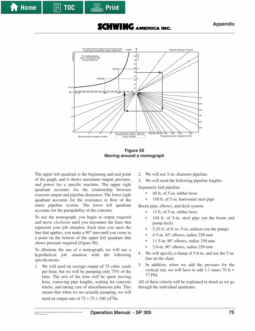
Appendix
SP 305Startup 250:Users:Danny:Desktop:Operation manuals:line pumps:maverick (P305):Appendix.fm Operation Manual - 75
The upper left quadrant is the beginning and end pointof the graph, and it shows maximum output, pressure,and power for a specific machine. The upper rightquadrant accounts for the relationship betweenconcrete output and pipeline diameters. The lower rightquadrant accounts for the resistance to flow of theentire pipeline system. The lower left quadrantaccounts for the pumpability of the concrete.
To use the nomograph, you begin at output requiredand move clockwise until you encounter the lines thatrepresent your job situation. Each time you meet theline that applies, you make a 90° turn until you come toa point on the bottom of the upper left quadrant thatshows pressure required (Figure 50).
To illustrate the use of a nomograph, we will use ahypothetical job situation with the followingspecifications:
1. We will need an average output of 75 cubic yardsper hour, but we will be pumping only 75% of thetime. The rest of the time will be spent movinghose, removing pipe lengths, waiting for concretetrucks, and taking care of miscellaneous jobs. Thismeans that when we are actually pumping, we will
need an output rate of 75 ÷.75 = 100 yd3/hr.
2. We will use 5-in.-diameter pipeline.
3. We will need the following pipeline lengths:
Separately laid pipeline:• 40 ft. of 5-in. rubber hose• 150 ft. of 5-in. horizontal steel pipe
Boom pipe, elbows, and deck system:• 13 ft. of 5-in. rubber hose• 144 ft. of 5-in. steel pipe (on the boom and
pump deck)• 5.25 ft. of 6–to–5-in. reducer (on the pump)• 4 5-in. 45° elbows, radius 250 mm• 11 5-in. 90° elbows, radius 250 mm• 2 6-in. 90° elbows, radius 250 mm
4. We will specify a slump of 5-6 in. and use the 5-in.line on the chart.
5. In addition, when we add the pressure for thevertical run, we will have to add 1.1 times 70 ft =77 PSI.
All of these criteria will be explained in detail as we gothrough the individual quadrants.
100
2000
200
300
400
500
600
800100012001500180025003000
2"
2.5"
3"4" 5" 6"
P in PSI
Q in
yd3
/hr.
Pipeline diameter in inches
Proportional value of pipeline in feet
For vertical placing,add 1.105 PSI per foot
of level difference.
Slump of fresh concrete in inches
6" 5" 4.5"
4"
87015666003000 2800 2600 2400 2200 2000 1800 1600 1400 1200 1000 800 400 200
200
180
160
140
120
100
80
60
40
20
67
116Rod side
Piston side
120/80 x 1600:200132 KW
Pumpkit Model:Power:
132 KW
(72600)TK number does not apply to truck mounted units.Curve shown is the Power Factor number (PF).
0004
55.e
ps
Figure 50Moving around a nomograph

Appendix
Operation Manual - SP 30576 revDate
The quadrants1. The upper left quadrant describes the power
curve of a given hydraulic pump Kw rating and themaximum output and maximum pressure of aparticular model of concrete pump (Figure 51).
Any concrete pump selected for a job must meet threetechnical parameters:
• the power factor number of the pump must beequal to or greater than the power factor num-ber of the job,
• the maximum output required by the job mustbe available from the pump, and
• the maximum pressure required by the jobmust be available from the pump.
It is important to notice the pump maximum pressureand maximum output, even if the power factor numberof the pump is larger than the job requires. Theseparameters are decided during the design stage of theunit and cannot be adjusted on the job. If the unit isable to go from rod side to piston side, maximumpressure and output can be exchanged—that is, you candecrease one while increasing the other the sameamount.
The power factor number (PF) replaces the TKnumber on a truck-mounted unit. It is the Kwmultiplied by a constant (550) that has several
efficiency factors figured in. When using anAmericanized nomograph (pressure in PSI and flow incubic yards per hour), the pressure multiplied by theoutput must always be less than or equal to the PF. Forexample, if you needed 50 cubic yards per hour anddetermined that this will require 750 PSI, you canmultiply 50 by 750, which equals 37,500. Any pumpyou select must have a PF of 37,500 or greater. If youare using a nomograph that has been converted tometric units of measure (pressure in bar and output incubic meters per hour), you can still multiply thepressure by the output, but you must multiply theanswer by the conversion factor between metric andEnglish units of measure to get the PF. The conversionfactor for cubic yards to cubic meters and for bar to PSIis 18.966. For all practical purposes, you can use 19.For example, if you need 50 cubic meters per hour anddetermine that your job setup will require 65 bar, youcan multiply 50 by 65, which equals 3250. Multiplythis by 19, and you find that your PF requirement is61,750. Again, any pump you select for the job in thisexample should have a PF of 61,750 or greater.
The maximum output (abbreviated as max Q) isdetermined by the size of the hydraulic pumps, thenumber of strokes per minute, and the size of thedifferential and material cylinders. The unit is usuallydesigned so maximum output can be achieved only at
P in PSI
Q in
yd3
/hr.
TK number does not apply to truck mounted units.Curve shown is Power Factor number (PF). 72600
132 KW
3000 2800 2600 2400 2200 2000 1800 1600 1400 1200 1000 800 600 400 200
200
180
160
140
120
100
80
60
40
20
For vertical placing,add 1.105 PSI per foot
of level difference.
Rod Side
Piston Side
0000
28.e
ps
Power curve
Kw rating
Power factor number(replaces TK)
Maximum output andmaximum pressure ofa specific unit
Figure 51Upper left quadrant

Appendix
SP 305Startup 250:Users:Danny:Desktop:Operation manuals:line pumps:maverick (P305):Appendix.fm Operation Manual - 77
less than maximum pressure.
Maximum pressure (abbreviated as max P) isdetermined by the size of the differential and materialcylinders and the setting of the main relief valve. To besure that the unit will handle the job, be careful tonotice max P and max Q. Here is an example of whythat is important: You contract to pump a job thatrequires only 20 yards per hour, but you calculate thatyou will need 2100 PSI pressure. The PF of this job is42,000 (20 x 2100). The pump shown in Figure 51 hasa TK of 72,600, so there is enough power available.However, the maximum pressure available from thepump is only 1570 PSI. This pump would not do thejob.
2. Follow the chart in a straight line from requiredoutput into the upper right quadrant until youcome to the size of the pipeline that you will use. Agood rule of thumb for sizing pipeline is to use thelargest diameter pipeline that you can. It takes lessforce to move concrete through a 6-inch pipelinethan, for example, a 4-inch pipeline. Whenpressure is exerted on concrete in a pipeline, apaste of water and cement fines coats the inside ofthe pipeline and forms a slippery layer on whichthe bulk of the concrete slides. While it is true that
a 6-inch pipeline has 49 percent more surface areato coat than a 4-inch pipeline, the volume ofconcrete that can move on the layer is increased by125 percent, which results in lower velocity of theconcrete (in feet per second), lower friction, and,therefore, lower pressure. A pump that may not becapable of completing a difficult job through 4- or5-inch pipe may be able to do it easily through 6-inch pipe. Note! Experience has taught us that 5-inch is the optimum pipeline size for lengthyvertical runs, such as those found on high-risebuildings. It is large enough for most aggregate butsmall enough that you minimize the amount ofconcrete that slides back into the hopper when theconcrete valve cycles, which we call backwash.You must also consider the people at the point ofplacement. Very few hose handlers, if any, canmove 6-inch hose on a slab all day. There is noprovision in the nomograph for mixing pipelinesizes. For example, if you will be reducing from 5-inch to 4-inch pipe, you should calculate the chartas if you were using 4-inch pipe for the entiredistance. This will not be completely accurate, butyou will be safe in your pressure calculation. In ourexample, we use 5-inch pipeline (Figure 52).
Q in
yd3
/hr.
Pipeline diameter in inches
6" 5" 4.5"
4"
000023.eps
Make a 90˚ turn whenyou intersect with thepipeline diameter thatapplies to your job.
Figure 52Upper right quadrant—Pipeline diameter
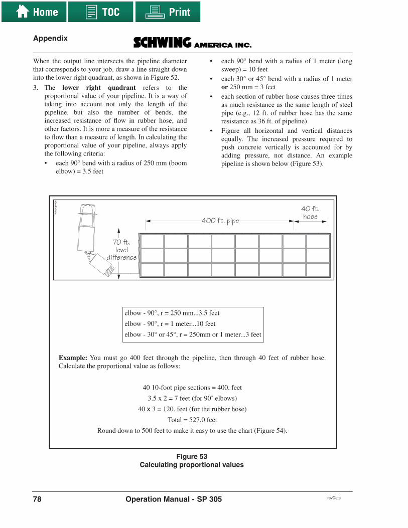
Appendix
Operation Manual - SP 30578 revDate
When the output line intersects the pipeline diameterthat corresponds to your job, draw a line straight downinto the lower right quadrant, as shown in Figure 52.
3. The lower right quadrant refers to theproportional value of your pipeline. It is a way oftaking into account not only the length of thepipeline, but also the number of bends, theincreased resistance of flow in rubber hose, andother factors. It is more a measure of the resistanceto flow than a measure of length. In calculating theproportional value of your pipeline, always applythe following criteria:• each 90° bend with a radius of 250 mm (boom
elbow) = 3.5 feet
• each 90° bend with a radius of 1 meter (longsweep) = 10 feet
• each 30° or 45° bend with a radius of 1 meteror 250 mm = 3 feet
• each section of rubber hose causes three timesas much resistance as the same length of steelpipe (e.g., 12 ft. of rubber hose has the sameresistance as 36 ft. of pipeline)
• Figure all horizontal and vertical distancesequally. The increased pressure required topush concrete vertically is accounted for byadding pressure, not distance. An examplepipeline is shown below (Figure 53).
40 ft. hose 400 ft. pipe
70 ft.level
difference
mav
prop
.eps
Example: You must go 400 feet through the pipeline, then through 40 feet of rubber hose.Calculate the proportional value as follows:
40 10-foot pipe sections = 400. feet
3.5 x 2 = 7 feet (for 90˚ elbows)
40 x 3 = 120. feet (for the rubber hose)
Total = 527.0 feet
Round down to 500 feet to make it easy to use the chart (Figure 54).
elbow - 90°, r = 250 mm...3.5 feet
elbow - 90°, r = 1 meter...10 feet
elbow - 30° or 45°, r = 250mm or 1 meter...3 feet
Figure 53Calculating proportional values

Appendix
SP 305Startup 250:Users:Danny:Desktop:Operation manuals:line pumps:maverick (P305):Appendix.fm Operation Manual - 79
When you have calculated the proportional value ofyour pipeline, extend your line down from the upperright quadrant until it intersects with the line thatrepresents your pipeline. When you reach theintersection, make a 90° turn clockwise into the lowerleft quadrant. As noted previously, we are using 500feet as our proportional value (Figure 54).
4. The lower left quadrant refers to the pumpability
of the concrete. If the concrete specifications allowa range in slump (for example 5–6 in.), always usethe lower end to be safe. In our example, we use 5-inch slump. Extend the line from the lower rightquadrant until it intersects with the 5-inch slumpline; then make a 90° turn clockwise. This will leadyou back into the upper left quadrant (Figure 55)through the pressure scale.
Proportional value of pipeline in feet
100
2000
200
300
400
500
600
800100012001500180025003000
000021.eps
Make a 90˚ turn whenyou intersect with theproportional value thatapplies to your job.
Figure 54Lower right quadrant—Proportional value of pipeline
2"
2.5"
3"4" 5" 6"
P in PSI
Slump of fresh concrete in inches
3000 2800 2600 2400 2200 2000 1800 1600 1400 1200 1000 800 600 400 200
000020.eps
Make a 90˚ turn whenyou intersect with theslump that applies toyour job.
Figure 55Lower left quadrant—
Pumpability of the concrete

Appendix
Operation Manual - SP 30580 revDate
As you can see by the chart in Figure 55, we arereentering the upper left quadrant through the pressurescale at about 550 PSI. Remember, we now have to addthe head pressure for our vertical rise. At 1.1 PSI perfoot of level difference and our 70-foot vertical run, wemust now add 1.1 x 70 = 77 PSI to the 550 PSI fromthe chart.
550 PSI + 77 PSI = 627 PSI
NOTE!When calculating the head pressure fromvertical runs, it doesn’t matter if thepipeline runs straight up and down or if itruns uphill at an angle. Only the leveldifference in feet is needed for the pressurecalculation. If the pipeline is runningdownhill, the operator will need specialknowledge, but you don’t need to add anyhead pressure to the nomograph.
The nomograph is now complete. The PF of our jobcan be calculated like this:
PF = PSI x yd3/hr
We need a unit that is capable of 627 PSI and 100 yd3/hr. The PF of this job is:
PF = (627 x 100)
PF = 62,700
The unit must have a PF over 62,700, and it must beable to pump 100 yd3/hr and 627 PSI simultaneously.Look at the pump shown in our sample nomograph(Figure 56).
• Can the unit pump at 627 PSI? Yes
• Can the unit pump 100 yd3/hr? Yes• Can the unit pump both simultaneously? No!
This unit will not do the job.
The engine is a little too small. The intersection of 100yards3/hr and 627 PSI has been plotted for visualrepresentation, but you can see immediately that the PFof the job (62,700) is bigger than the PF of the unit(56,650). The curved black line represents the PF of theunit. If the unit is going to be able to handle the job, theintersection of pressure and yd3/hr will be to the rightand down from the curved line. Anything to the left orabove the line is beyond the power of the hydraulicpumps. If we could order this same unit with the pumpsset to a higher Kw, the PF of the higher Kw unit wouldbe 72,600, which would be sufficient.
Plotting the intersection of our hypothetical job again,you can see that it falls within the power zone of thehydraulic pumps (Figure 57).
P in PSI
Q in
. yd3
/hr.
Power factor number (PF)
Wor
king
pow
er (
in k
W)
For vertical placing,add 1.105 PSI per foot
of level difference.
56,6
50
103 KW
English to Metric Conversion Factor is PF 18.966
3000 2800 2600 2400 2200 2000 1800 1600 1400 1200 1000 800 600 400 200
200
180
160
140
120
100
80
60
40
20
Example Job
000019.eps
Figure 56Is this unit sufficient for the job?

Appendix
SP 305Startup 250:Users:Danny:Desktop:Operation manuals:line pumps:maverick (P305):Appendix.fm Operation Manual - 81
Bearing in mind that the nomograph should only beconsidered accurate to within ±10 percent, you shouldalways calculate conservatively, and allow for thegraph tolerance. In the case of the pump in Figure 57,we should still be safe even if the pressure requiredwere 10% greater (690 PSI).What if you already ownthe pump shown in Figure 56? Is there anything thatcan be done to the job specifications to make the unitwith the less powerful pumps work? You could use thesmaller PF unit shown in Figure 56 if you can getpermission to do any of the following things:
• Pump the top of the building at 85 yd3/hr
instead of 100 yd3/hr.• Pump the top of the building at a 6-inch slump
instead of 5-inch. (This would still be withinspecifications.)
• Remove some of the rubber hose at the end ofthe horizontal run. Normally, with job circum-stances that did not require a substantial verti-cal run, you could also use 6-inch instead of 5-inch-diameter pipeline. But in our example, theentire vertical run was made with the boom.The boom can never support 6-inch pipeline.
P (in PSI)
Q (i
n yd
3 /hr
)
Power Factor number (PF)
W
orki
ng p
ower
(in
kW
)
For vertical placing,add 1.105 PSI per foot
of level difference.
72,6
00
132 kW
English to Metric Conversion factor is PF 18.966
3000 2800 2600 2400 2200 2000 1800 1600 1400 1200 1000 800 600 400 200
200
180
160
140
120
100
80
60
40
20
Example Job
000018.eps
Figure 57Same model pump with larger Kw hydraulic pumps

Appendix
Operation Manual - SP 30582 revDate
Minimum Pipe Wall Thickness
PIPE WALL THICKNESS
0.025"
.050".075"
.100".125"
.150".175"
.200".225"
.250".275"
.300".325"
.350".375"
0
200
400
600
800
1000
1200
1400
1600
1800
2000
2200
2400
2600
2800
3000
3200
3400
3600
3800
4000
4200
0
10
20
30
40
50
60
70
80
90
100
110
120
130
140
150
160
170
180
190
200
210
220
230
240
250
260
270
280
290
300
SCHEDULE 40(1/4 wall)
9 gauge 3/16”11 gauge 7 gauge
MA
TE
RIA
L P
RE
SS
UR
E
BARPSI
1. This chart assumes a safety factor of 2:1. Higher safety factors may be required in some circumstances.2. Wear reduces wall thickness. Thickness must be checked on a regular basis.3. Pressures may be limited even more by clamp style or pipe end used.4. The chart is based on 62,000 PSI tensile strength. Heat-treated calculations are based on 120,000 PSI tensile strength.5. The chart is for pressure calculations ONLY. There is no allowance for mechanical forces other than pressure, and thicker
walls may be needed for mechanical strength because of support or restraint considerations.6. The chart does not take into account metal fatigue caused by pressure cycles.
Note! This chart is intended as a guide for concrete pumping applications and is subject to the notes, assumptions, and conditions listed above. Any other use of this chart is not recommended.
This chart does not apply to double-wall pipe. Double wall pipe can be checked by inspecting the inside of the pipe. If the insert is intact, the pipe is okay. If the insert is worn through, the pipe must be replaced. Contact your pipe supplier for the pressure capacity of your double-wall pipe.
pipe
wal
lvsP
ress
2.ep
s
.heat treated .standard
4“ H
EAT
TREA
TED
5“ H
EAT
TREA
TED
6“ H
EAT
TREA
TED
4.8”
& 4
.9“ H
EAT
TREA
TED
4.4”
HEA
T TR
EATE
D
4.9“ (7, 9
, 11 gauge) s
ystem
(125 m
m)
6“ syste
m
5“ syste
m4.0“ s
yste
m 4.4“ sys
tem
4.8“ syste
m
0.12
0”
0.15
0”
0.17
7”
0.18
8”
0.25
0”
Minimum Pipe Wall Thickness As a Function of Pressure

Appendix
SP 305Startup 250:Users:Danny:Desktop:Operation manuals:line pumps:maverick (P305):Appendix.fm Operation Manual - 83
PictogramsShown below are the pictograms used on the SP 305along with a brief description of each.
Local / Remote
Pump ON Local control
Remote control
Off
reverse
forward
Concrete pump
OPERATOR'S PANEL
REMOTE CONTROL BOX
Concrete pump
on
offreverse
forward
Mavpictograms.eps
oil pressure
oil temperature
charging system
+-

Appendix
Operation Manual - SP 30584 revDate
Decal Location Guide
SAFETY LABELS (1 of 2)
10/01/04 Rev 1 P 305
30390771
30390771
30390771
30390771
30390772
30390772
30336985
30336985
30336983A
30392275
30309999C
30309999C
30390178
30390178
30394795
30394795
30333268
30390161
30390161
ENGINEMAINTENANCE
30301733F3039020730332668B
30306123C30393651
30335000A
30333578
30364520A
30364521
30364520A
30364521
30362340
30363822
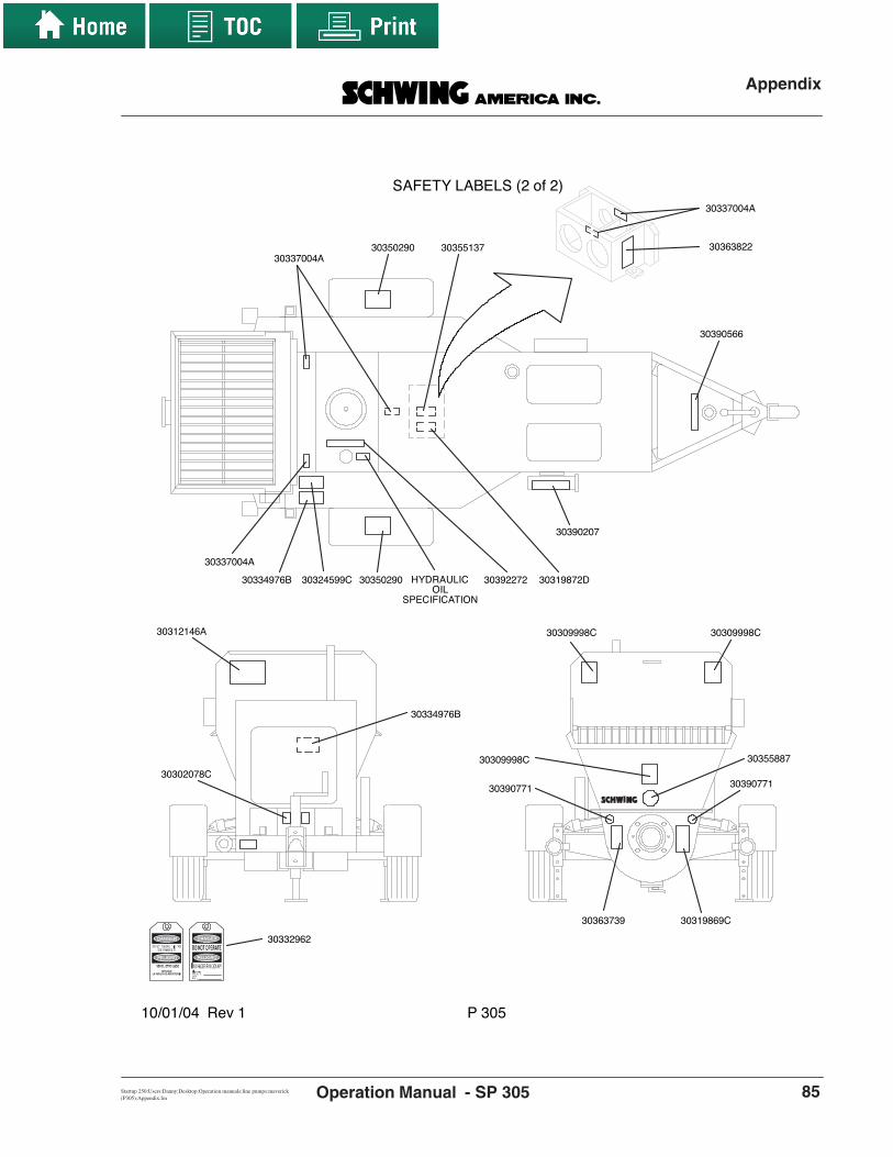
Appendix
SP 305Startup 250:Users:Danny:Desktop:Operation manuals:line pumps:maverick (P305):Appendix.fm Operation Manual - 85
SAFETY LABELS (2 of 2)
10/01/04 Rev 1 P 305
30337004A
30350290
30350290
30390566
30390207
30319872D3039227230324599C30334976B
30309998C30309998C
30390771
30309998C
30319869C
30334976B
30302078C
30312146A
30390771
30337004A
30337004A
30355887
30363822
30363739
30355137
HYDRAULICOIL
SPECIFICATION
30332962

Appendix
Operation Manual - SP 30586 revDate
Glossary of TermsThe following list defines some terms used in thismanual.
AccumulatorA hydraulic device that stores fluid power energyin much the same way that a capacitor storeselectrical energy. Because an accumulatorstores energy, it must be drained and depressur-ized before work begins on an actuator orhydraulic system equipped with an accumulator.
Agitator or Re-MixerA device set in the concrete hopper to keep con-crete moving, which prevents it from setting. It istypically a rotating shaft to which several paddleshave been mounted. See also: Hopper Grate
AWS D1.1The code for structural welding with steel, asdefined by the American Welding Society. Sec-tions 3, 5, and paragraph 9.25 of section 9 apply.See also: Certified Welder and EN 287-1
Black and WhiteIf a boom is black and white it means that thespeed of the boom is not proportional to themovement of the joystick. Speed can only becontrolled by feathering of the joystick.
Blanking PlateAlso known as a blanking plug or end cap. Itspurpose is to prevent material from falling out ofthe delivery system (typically the end hose) whenmoving a full boom over personnel or property.
BlockageIf the pump is pushing and concrete fails to comeout at the point of discharge, a blockage is thecause. The causes of blockages are detailed insection 6.18 of this manual. Blockages can cre-ate dangerous situations by causing high con-crete pressure combined with the sometimesuncoordinated efforts of untrained workers toremedy the problem.
Bulk DensityThe mass of a substance per volume. For exam-ple, 1 cubic foot of air weighs much less than 1cubic foot of water. One cubic foot of lightweightconcrete weighs less than 1 cubic foot of steel-entrained concrete. We could say that steel-entrained concrete has a higher bulk densitythan lightweight concrete. All calculations for theoperation manuals and specifications of concretepumps are based upon 150 pounds per cubic
foot, which is the approximate mass of hard rock(normal) concrete.
Certified OperatorAn operator who has been issued a certificationcard by the American Concrete Pumping Associ-ation. There are several classes of certification,each relating to a different category of pump. Foran operator to become certified, he or she mustpass tests regarding operation, setup, andcleanout for each category of pump. They mustalso pass the safety rules test common to all cer-tification categories, meet the experiencerequirements set forth for each category, andmaintain a safe and clean driving record. Certi-fied operators are considered qualified operatorsin their categories. See also: Expert, QualifiedOperator
Certified WelderAs it relates to concrete pumping and this safetymanual, a Certified Welder is a person who hasapplied for, taken, and passed the AmericanWelding Society (AWS) or the European Normal(EN) test for structural steel welding. Anyonewelding on a concrete pump placing boom, out-rigger, tower, or other device must be certified toAWS D1.1 sections 3, 5, and paragraph 9.25 ofsection 9 and/or EN287-1/PREN288-3.
Concrete PressureThe force per square area that is exerted on theconcrete. The concrete pressure is always a ratioin direct proportion to the hydraulic oil pressureon the concrete pump circuit. See also: MaximumPressure
ConductorsMaterials that conduct electricity. Copper, silver,aluminum, gold, steel, and water are consideredgood conductors of electricity. Air, fiberglass, rub-ber, ceramics, and glass are considered poorconductors. All of these conductors have a resis-tance to the flow of electricity, which is measuredin terms of ohms per linear foot. As voltageincreases, more current flows through the sameresistance. With high-voltage electric wires—8000 volts, for example—even poor conductorscarry enough current through your body toground to kill you. (As little as 35 milliamps cancause cardiac arrest.) Some conductors, such asair, resist electricity very well, but if the voltagegets high enough, current will flow. (Lightning is agood example of this.) See also: Electrocution

Appendix
SP 305Startup 250:Users:Danny:Desktop:Operation manuals:line pumps:maverick (P305):Appendix.fm Operation Manual - 87
DecibelsA measurement of volume equal to one tenth ofa bel, abbreviated dB. As it applies to concretepumps, it is a measurement of the sound pres-sure level one meter away from a noise source.Because constant exposure to loud sound cancause permanent hearing loss, OSHA has devel-oped guidelines for time limits on exposure tosound at different volumes. The chart is in sec-tion 8.14 of the Safety Manual.
Drive EngineThe primary source of power for a hydraulic sys-tem. Typically, the word engine denotes an inter-nal combustion device, whereas the word motordenotes an electrical device. See also: PrimeMover
ElectrocutionMade by combining the words “electric” + “execu-tion.” It means “death by electricity.” See also:Conductors
EN 287-1 / PREN 288-3The code for structural welding with steel asdefined by the European Norm. See also: Certi-fied Welder
ExpertAs used in this safety manual, an expert isdefined as a person who, on the basis of special-ized training and experience, has developed ahigh degree of knowledge and skill in the areasof concrete pumps, concrete pumping, cleanoutprocedures, generally accepted engineeringnorms, and safety regulations to the extent ofbeing able to evaluate equipment and processesas they relate to job safety. Experts demonstratetheir knowledge and abilities by passing the certi-fication testing and experience requirements ofthe American Concrete Pumping Association.Other experts may include master mechanicsand after-sales service technicians of the manu-facturer. See also: Certified Operator
Fast SwitchA secondary hydraulic circuit added to single-cir-cuit machines to disable the stroke limiter duringthe switch of the Rock Valve cylinder, therebymaking the Rock Valve switch quickly. This circuitis not needed or available on twin-circuitmachines.
Foreign MaterialMaterial that was never intended to be pumpedbut ends up in the concrete hopper. Examples of
foreign material include small animals, hammers,ready-mix truck fins, unmixed clumps of cement,hardened concrete that breaks away from ready-mix truck fins, and soft drink cans. Many of theseitems can create a blockage if they are pumpedthrough the system.
Go DevilA plug made from a rubber composite, usuallywith several fins that expand to seal when pres-sure is applied. Go devils are intended to beinserted in a steel delivery pipeline and pushedwith water or compressed air for the purpose ofcleaning the pipe. Not to be used with rubberhose or short sections of pipe. See also: SpongeBall
GuideAn assistant brought in to help with backing up atruck or trailer or with other circumstances inwhich the driver cannot see enough to ensuresafety. See also: Spotter
High VoltageFor the purposes of this manual, any current over120 volts AC is considered high voltage. In theUnited States, electrically driven concrete pumpsnormally operate the motors at 480 volts AC(high voltage) and the controls at 24 volts DC(low voltage). With electric wires in residential orindustrial areas, the voltage is approximately8000 volts to ground or 13,800 volts from phaseto phase (distribution voltage). When dealingwith electric wires that are mounted high abovethe ground on steel towers, the voltage rangesfrom 100,000 to 1,000,000 volts (transmissionvoltage).
Hopper GrateA meshwork typically made from steel bars andplaced over the concrete hopper. It serves tokeep human body parts away from the agitator(when left in its proper position) and to keeplarge foreign objects from falling into the hopper,which could cause blockages if they werepumped. The hopper grate must be secured inposition in order to be effective.
Jacking the OutriggersAdjustment of the outriggers in the vertical direc-tion. With boom-mounted concrete pumps, youshould strive to make the adjustments so that theunit sits within 3° of level.

Appendix
Operation Manual - SP 30588 revDate
Licensed ElectricianA qualified electrician licensed by the state,county, or municipality where the connectionsare to be made. In some locations, electriciansare not required to be licensed, but the workshould still be completed by a competent profes-sional. Under no circumstances should high-volt-age connections be made by a concrete pumpoperator or related personnel.
MaintenanceAll procedures for servicing, inspection, andrepair of concrete pumps and related equipmentand devices. Maintenance and inspection aremethods of maintaining the desired state of theequipment. Repair is the method of restoring thedesired state of the equipment.
Maximum PressureWhen talking about a hydraulic system, maxi-mum pressure refers to the highest pressure thatcan be achieved with the settings of the circuitrelief valves. When discussing concrete output,maximum pressure refers to the pressure thatwill be developed if the hydraulic system pres-sure reaches the relief valve setting. Concretepressure is always the force at which the differ-ential cylinders are moving, divided by the cross-sectional area of the concrete cylinder. Maximumconcrete pressure, then, is developed when thedifferential cylinders are moving with maximumforce, which is determined by the hydraulic sys-tem relief valve setting. During normal pumping,the resistance of moving the concrete throughthe pipe or boom creates the pressure neededby the pump and is well under the maximumpressure. See Also: Concrete Pressure
Minimum Safety DistanceIn this manual, the term “minimum safety dis-tance” refers to the closest distance that you areallowed to approach an object or electrical wireswhile leaving room for errors in human judgmentor machine malfunction. The distance from elec-trical wires in the United States is 17 feet, as rec-ommended by the American Concrete PumpingAssociation. This distance may have other valuesin different countries.
Murphy’s LawAn old adage that says: “Anything that can gowrong, will go wrong, and at the worst possiblemoment.”
Operational AreaThe area around a working piece of equipmentor point of discharge where dangers can beencountered because of the nature of the
machinery or process in use. For safety reasons,do not allow unauthorized presence in the opera-tional area.
OSHAOccupational Safety and Health Administration.A branch of the U. S. federal government thatdeals with job safety. It establishes and enforcessafety regulations for industry and business. Oneof the areas over which it has authority is con-struction job sites and workshops.
Personal Protective ApparelThings you can wear to protect yourself frompotential dangers in a concrete placing environ-ment. Examples are:
• snug-fitting work clothes• steel-toed work boots• lime-resistant gloves• safety glasses• ear muffs or ear plugs• rubber boots for when you have to stand in
concrete• hard hat
Point of DischargeThe location on the machine from which concreteis expelled from a delivery system. This can bethe point of placement (the actual form that isbeing filled with concrete) or the cleanout areaafter completion of a job.
PourUsed by the concrete pumping industry and inthis manual as a noun. It is the specific job for thepump during any given time period, e.g. “We’llgrab lunch right after the pour.”
Prime MoverThe primary power source for a hydraulic sys-tem. The term “prime mover” denotes neither aninternal combustion engine nor an electric motor.
ProportionalProportional movement means the speed that aboom or outrigger travels is proportional to theamount of movement on the control handle (joy-stick or outrigger handle).

Appendix
SP 305Startup 250:Users:Danny:Desktop:Operation manuals:line pumps:maverick (P305):Appendix.fm Operation Manual - 89
PTO (Power Take Off)A switchable output from the transmission or anintermediate gearcase. On a concrete pump, thePTO is used to divert the power from the engineand drive train to turn the hydraulic pumps.
Qualified OperatorAn individual who meets all the following qualifi-cations:
• reached the age of 18• is physically and mentally capable• has been trained in the proper operation
and maintenance of the pump and placingboom, if applicable
• has demonstrated his or her capabilities tothe hiring company with respect to theoperation and maintenance of the pumpand placing boom
• can be expected to perform assignedduties in a reliable manner
Qualified PersonnelA generic term used to describe people who arequalified to do work in their area of application.For example, having your boom repairsinspected by “qualified personnel” before userefers to inspection by a certified welder or certi-fied welding inspector. Having repairs to yourhydraulic system done by “qualified personnel”would refer to repairs made by qualified work-shop personnel.
Qualified Workshop PersonnelAn individual who meets all of the following quali-fications:
• has reached the age of 18 years • is physically and mentally capable• has been trained in proper repair, mainte-
nance, and inspection procedures plus thepertinent safety rules for concrete pumpsand related equipment
• has demonstrated their capabilities to theircompany with regard to the proceduresand rules discussed above and
• can be expected to perform assignedduties in a reliable manner
Rock JamA specific type of blockage caused when thecement and fines of the concrete are not presentin sufficient quantity to fully coat the larger aggre-gates and the walls of the delivery system. Inthese cases, the rock (larger aggregates of themix) form a wedge inside the pipe. Resistance tomovement then becomes overpowering, and theconcrete stops. Increasing pressure to try to
remove the wedge only results in forcing more ofthe finest particles past the rocks, compoundingthe problem. In some cases, the wedge can bebroken up by alternately pumping in forward andthen reverse. See also: Blockage
Separate PipelineA pipeline, other than the placing boom pipeline,that is laid between the concrete pump and thepoint of discharge.
Shutoff ValveIn hydraulics: a valve with the ability to stop theflow or pressure of hydraulic oil. Must be able towithstand the maximum pressure of the hydrauliccircuit that it controls. In concrete: A manually orhydraulically operated valve that prevents theflow of concrete in either direction. Some con-crete shutoff valves also have the ability to divertthe flow of concrete to a different pipeline; forexample, to a discharge point for cleanout. Theshutoff valve must be able to withstand the maxi-mum pressure on the concrete of which thepump is capable.
Single CircuitThe plumbing method used for the pumpkit inwhich both the differential cylinders and the RockValve cylinder are moved by the main hydraulicpumps. Single-circuit machines are not equippedwith an accumulator.
Soft SwitchA secondary hydraulic circuit added to twin-cir-cuit machines to account for the oil coming fromthe main hydraulic pumps while the Rock Valve isbeing switched by the oil from the accumulator.
Soil PressureThe force per square area that is exerted on theground by the outrigger legs. The amount ofpressure that the soil will support varies with thecomposition and compaction of the soil. To deter-mine the stability of the soil, see the chart in sec-tion 5.16 of this manual.
Sponge BallA medium-to-hard, spherical sponge used toclean the inside of delivery pipelines. See Also:Go Devil
SpotterA spotter is a person who stands at a vantagepoint where he or she can see both the point ofdischarge and the pump operator. The spotteruses two-way radios or hand signals to direct the

Appendix
Operation Manual - SP 30590 revDate
operator to operate the unit as required by thejob circumstances. A spotter can be anyone whois familiar with the safety rules for the pump andworkers and is equipped with a radio or knowsthe appropriate hand signals. A spotter is neededwhenever the operator cannot safely see thepoint of placement or the distance between theunit and an unsafe area. See Also: Guide
Sucking BackThe act of putting the concrete pump into thereverse mode for any of several reasons. Someexamples of reasons to suck back:
• To relieve pressure in the delivery systembefore opening when a blockage hasoccurred.
• To clean the boom with a sponge ball uponcompletion of the pour.
• To remove concrete from the boom for thepurpose of folding the boom for moving.
Thrust BlockAlso known as a “dead man.” This is a large blockof poured concrete, usually with one or moresweep elbows cast inside, placed at the bottomof a vertical run for the purpose of supporting theweight of the vertical run and for lateral stabiliza-tion of the pipeline. It stabilizes and supports thevertical run by virtue of its enormous mass (nor-mally one cubic yard or larger).
Towing VehicleIn this manual, the term “towing vehicle” appliesonly to trailer- mounted concrete pumps. It is thevehicle you use to tow the trailer on the road, job-site, or in the yard. The size and condition of thetowing vehicle are extremely important in theseapplications. See the safety rules regarding thissubject in section 4 of this safety manual.
Transport Position“Transport Position” refers to the position of theboom during transport. For transport, the boomis completely folded and lowered into the rests,and the boom straps are secured. When stowingin the traveling position because of a thunder-storm, however, the boom straps need not besecured if no travel is imminent.
Twin CircuitThe plumbing method used for the pumpkit inwhich the differential cylinders are moved by themain hydraulic pumps but the Rock Valve ismoved by the oil stored in an accumulator.
UnauthorizedWithout authority, without permission. Examples:Unauthorized operation of the boom could beoperation by a passing teenager. Unauthorizedrepairs to the boom could be repairs made with-out the manufacturer’s permission.
Unintentional MovementMovement of the pump, boom, or related equip-ment without a specific, intentional command bythe operator. An example of an unintentionalmovement is if an operator fell while walking withthe remote control box and accidentally hit a joy-stick, which caused a boom movement. Uninten-tional movement can be avoided by disabling thehydraulic system with the emergency stopdevices when the unit is not in immediate use.
Vertical RunSections of concrete delivery pipeline that run inan up and down direction. Vertical runs have veryspecific procedures and rules for installation,support, cleaning, and inspection. Concretepumping personnel should, therefore, have spe-cific training in these procedures and rulesbefore attempting to use them in a job setting.
Water JetThe stream of water that comes out the end of awater hose or pressure washer. The water jet isthe only part of the water system that needs togo into the hopper, concrete valve, or waterboxfor cleaning.
Additional Reading MaterialThis is a partial list of the books that have been writtenon the subject of concrete pumping. Omission of anyrelevant books was done so unintentionally.
• Pumping Concrete and Concrete Pumps, KarlErnst v. Eckardstein. F. W. Schwing GmbH,1983.
• Pumping Concrete—Techniques and Applica-tions, Robert Allen Crepas. Aberdeen Group,1991.
• Nomographs—A Guide to Usage, RobertEdwards. Schwing America, Inc., 1992.

Appendix
SP 305Startup 250:Users:Danny:Desktop:Operation manuals:line pumps:maverick (P305):Appendix.fm Operation Manual - 91
List of Lubricants and NitrogenThis list describes the materials that were installed inyour concrete pump unit when it left the factory. Otherbrands of lubricants and their usage are described inthe following lists.
Hydraulic oil
Gearcase oil
Truck fluid levels
Compressor oil
Grease for gears and spline couplers
Grease for autogreaser
Dry nitrogen
Texaco Rando 46
Mobilube® HD 80w-90
See owners manual for your specific truck
Mobil Rarus 427 or 429
Castrol Industrial-Optimoly Paste White
Mobil Grease HP or CM-S
Any brand of dry nitrogen is suitable forrecharging accumulators
Materials.eps

Appendix
Operation Manual - SP 30592 revDate
Hydraulic OilsISO viscosity VG 32 = Winter in northern US and CanadaISO viscosity VG 46 = Summer in northern US and CanadaISO viscosity VG 68 = Tropical areas, desert summers, indoor uses
• The following table shows the characteristics of Rando HD 46. You may use this information for comparison with other brands.
• Some oil manufacturers offer vegetable-based hydraulic oils, which are considered environmentally friendly (the additive packages are not inert, however). These vegetable-based oils must NEVER be mixed with mineral-based oils. A complete flush of the hydraulic system must be performed when changing to this type of fluid. See the list below for a sample of the available oils and viscosities.
OM14
Brand
Texaco Rando HD* Texaco Rando HDZ**Mobil DTEShell TellusAral VitamBP - EnergolEsso - NutoTotal - Azolla
VG 32 / HLP HD 32
HDZ 32 DTE 24
32GF 32
HLP 32H 32 ZS 32 HS 32
Viscosity / DIN quality designation VG 46 / HLP
HD 46HDZ 46DTE 25
46GF 46
HLP 46 H 46 ZS 46 HS 46
VG 68 / HLP HD 68
HDZ 68 DTE 26
68GF 68
HLP 68 H 68 ZS 68 HS 68 Wintershall - Wiolan
* Rando HD 46 is installed in new machines at the Schwing Factory - standard** Rando HDZ is available for installation in new machines from the Schwing Factory - optional
BrandTexaco Biostar Hydraulic 32 Texaco Biostar Hydraulic 46Mobil EAL 224-HShell Naturelle HF-M
Vegetable Based Hydraulic OilsViscosity Information
Considered equivalent to ISO VG 32 viscosityConsidered equivalent to ISO VG 46 viscosityConsidered equivalent to ISO VG 36 viscosityConsidered equivalent to ISO VG 42 viscosity
ISO Viscosity
Class
Viscosity cST @ 40 C
Viscosity cST @ 100 C
Viscosity Index
GravityAPI
Flash point
F
Pour point
F
Foam, Seq IIml foam @ 0/10
minutes
VG 32 30.1 5.3 106 30.7 385 -25 20/0
VG 46 46.2 6.9 105 29.3 425 -20 20/0
VG 68 65.5 8.7 103 28.6 445 -20 20/0

Appendix
SP 305Startup 250:Users:Danny:Desktop:Operation manuals:line pumps:maverick (P305):Appendix.fm Operation Manual - 93
Gearcase Oils
Compressor Oils
A) for distribution gearcases
B) for motor vehicle gearcases
• The order of the list is meaningless. Any oil that meets the DIN quality designation and ISO viscosity specification may be used.
• The lubricants listed above are suitable for continuous ambient temperatures of -10 C (14 F) to +40 C (104 F). For conditions outside of this range, contact the oil manufacturer for recommendations.
• Viscosity class 220 roughly corresponds to SAE 90.
• Use VG 100 oil when ambient temperature is 0 to 10 C (32 to 50 F).
• Use VG 150 oil when ambient temperature is above 10 C (50 F).
Brand
TexacoMobilShellAralBPEssoWintershall
Viscosity / DIN quality designation VG 220 / CLP
Meropa 220Mobilgear 630Omala Oil 220
Degol BG 220, Degol BMB 220Energol GR-XP 220
Spartan - EP 220Wiolan - IT 220
Brand
TexacoMobilShellAralBPEssoWintershall
Viscosity / Mil-L quality designation 90 (85w-90) / 2105 B
Geartex EP-CMobilube HD
Spirax HD, Spirax MBGearbox Oil HYP
Energear Hypo 90, Hypogear 90 EPGear Oil GX-D, Gear Oil GX
Wiolan Hypoid Gearbox Oil 90
Brand
TexacoMobilShellAralBPWintershall
ISO Viscosity / DIN quality designation VG 100 / VDL
Compressor Oil - EP 100Rarus 427
Corena - H 100Motanol - HE 100Energol - RC 100Wiolan - CD 100
VG 150 / VDLCompressor Oil - EP 150
Rarus 429Corena - H 150
Motanol - HE 150Energol - RC 150Wiolan - CD 150
OM
15

Appendix
Operation Manual - SP 30594 revDate
Grease
A) For filling the automatic greasers
B) For all other bearings
• The order of the lists is meaningless. Any grease that meets the quality designation and viscosity specification may be used.
• Shell Alvania is installed in new machines at the Schwing factory.
• Any equivalent grease may be used.
OM19A
Brand
TexacoMobilShell
Viscosity / DIN quality designation EP 2 / CLP Starplex 2
Mobilgrease HPAlvania EP - 2
Brand
Texaco
ShellAralBPEssoOptimal
Viscosity / Pressure rating 2 / EP
Multifak EP-2Mobil Mobilith AW 2
Alvania grease R 2HLP 2
Energrease LS2Multipurpose grease Beacon 2
Olitsta longtime 3 EP

Appendix
SP 305Startup 250:Users:Danny:Desktop:Operation manuals:line pumps:maverick (P305):Appendix.fm Operation Manual - 95
Hydraulic Schematic—Concrete Pump SP305 - Schematic
T
M
HY
DR
AU
LIC
SC
HE
MA
TIC
P30
5
Not
e:P
ress
ures
are
set
to th
e ac
cura
cy o
f the
gau
ge a
s re
ceiv
ed fr
om th
e m
anuf
actu
rer.
Rev
. 032
508
SA
IE 1
0260
Cha
nge
initi
als
New
rel
ease
MB
mm 3.1
mm 3.1
1.5
mm
XB
1
B1
XB
XP
P
MP
1
BA
T
P
MP
P
X
T1
MP
S
XA
1
A2
B2
A1
XA
XR
SP T2 T
S1 NG
6
S2
S3
1450
psi
450
bar
1800
psi
124
bar
2900
psi
200
bar
2500
psi
172
bar
30 p
si2
bar
35 p
si2.
4 ba
r
A10
V 4
5 D
FL
RC
oo
ler
10u
Filt
er
Ag
itat
or
E-S
top
Ag
itat
or
(Op
tio
nal
)
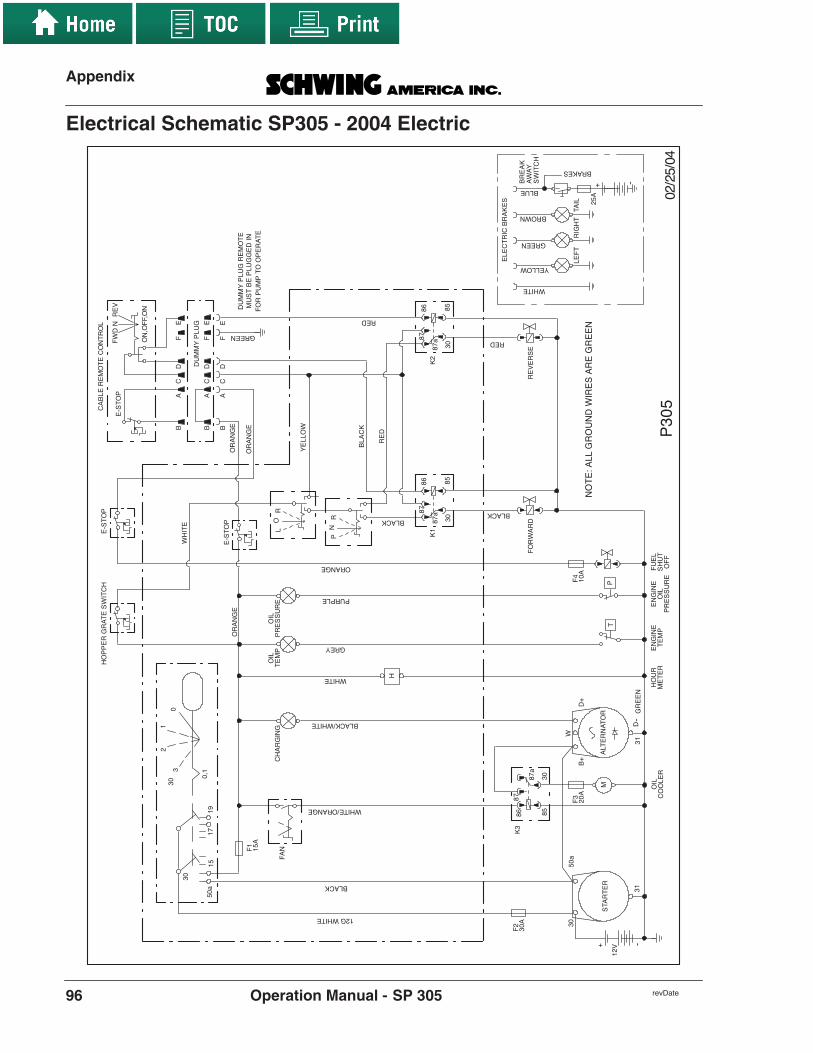
Appendix
Operation Manual - SP 30596 revDate
Electrical Schematic SP305 - 2004 Electric
40/52/20503
PKC
ALB
WOLL
EY
EG
NA
RO
EG
NA
RO
PO
TS-
EH
CTI
WS
ET
AR
GR
EP
PO
H
ETI
HW
PURPLE
ORANGE
LIO T
GREY
1F
GNI
GR
AH
C
0
12
30 3
1,0
BLACK/WHITE
+D
+B
RO
TA
NR
ET L
A
EG
NA
RO
9 171
W
51a 05
03
12GWHITE
NAF
H
PO
TS-
E
a0503
RE
TR
ATS
13
V21
--+
LE
UF
NE
ER
G13
--D
P
1K
LO
R
5803
a78
786 8
GUL
PY
MM
UD
RED
GREEN
LO
RT
NO
CE
TO
ME
REL
BA
C
PO
TS-
E
EF
DC
AB
EF
DC
AB
EF
DC
AB
A 51
ENI
GN
ER
UO
HE
NIG
NE
LIO
BLACK
TU
HS
FF
OP
ME
TLI
OR
ET
EM
ER
US
SE
RP
0 358
a 78
7868
3K
LIOM
RE L
OO
C
2F
A03
WHITE
ER
US
SE
RP
PM
ET
2K
5803
a78
7868
ES
RE
VE
RD
RA
WR
OF
PN
R
LIAT
TH
GIR
TF
EL
BROWN
YELLOW
WHITE
GREEN
BLUE
KA
ER
BY
AW
A
BRAKES
--+
HC
TIW
S
SE
KA
RB
CIR
TC
ELE
A52
DW
F
NO,F
FO,
NO
VE
RN
ET
OM
ER
GUL
PY
MM
UD
NID
EG
GUL
PE
BT
SU
ME
TA
RE
PO
OT
PM
UP
RO
F
BLACK
DE
R
BLACK
WHITE/ORANGE
NE
ER
GE
RA
SE
RIW
DN
UO
RG
LLA:
ET
ON
RED
3F
A024
FA01

Appendix
SP 305Startup 250:Users:Danny:Desktop:Operation manuals:line pumps:maverick (P305):Appendix.fm Operation Manual - 97
Electric Schematic CE/Tier III SP305E
LE
CT
RIC
AL
SC
HE
MA
TIC
S
SP
305
CE
Tie
r/C
OM
III
SP30
5--
CE
Tie
r/C
omII
I

Appendix
Operation Manual - SP 30598 revDate
Nomograph SP 305
P 305
P in PSI
Q in yd3/hr.
600400
200
30
6020 40
1000800
625
Technical identification number (TK)
Metric to English Conversion factor is TK x 18.966Pow
er:
Model:
By:N
umber:
Max Q
Revision date:
Power:
Model:Number: Max Q
Revision date:
P 305
30 Kw
36 Kw
054
RE
071305102 l/m
2.5/1.75 x 30:5Pum
pkit Model:
P 305
30 Kw36 Kw
054071305
102 l/mPipeline diam
eter in inches
Proportional value of pipeline in feet
For vertical placing,add 1.105 PSI per foot
of level difference.
Slump of fresh concrete in inches
30 Kw36 Kw
100
2000
200
300
400
500
600
8001000
12001500
18002500
3000
2"
2.5"3"4"5"6"
6"5"
4.5"4"
3" *2" *
*estimate
TK 750(14225)TK 900(17069)
Revision: 071305, add 36Kw, R
E

Appendix
SP 305Startup 250:Users:Danny:Desktop:Operation manuals:line pumps:maverick (P305):Appendix.fm Operation Manual - 99
Output Chart available upon request

Appendix
Operation Manual - SP 305100 revDate
NOTES

SP 305 OPERATION MANUAL
INDEX

Alphabetical Index
Operation Manual - SP 305102 revDate
Alphabetical Index
Aaccumulator
charging ....................................................50additional reading material list .......................90aggregate
guide for sizing pipeline ...........................22appendix
additional reading material .......................90fitting/wrench sizes ...................................64glossary of terms .......................................86hydraulic oil viscosity chart ......................62minimum pipe wall thickness chart ..........82output chart ...............................................68pictogram list ............................................83recommended emergency hose kit ............64torque specifications .................................63using nomographs .....................................74
Bboom pipeline
wall thickness chart ...................................82breakaway switch ............................................23bypass check valve
oil filter .....................................................41
Ccaution ...............................................................6charging the accumulator ................................50chocking ..........................................................23concrete
mixes .........................................................27preparation ................................................27
control deviceslocations ....................................................25
controlling the pumpinstructions ................................................25
coupling comparisonweld-on ends .............................................67
couplingsgrooved type .............................................67heavy-duty type .........................................67male/female o-ring type ............................67metric type ................................................67victaulic type .............................................67
crank armgreasing .....................................................24
cribbing ...........................................................23
Ddanger ................................................................6decal and warning labels ordering ..................19decals
location guide ............................................84dummy plug
remote cable ..............................................28
Eelectric brakes .................................................22electrical system
notes ..........................................................27emergency hose kit
recommended ............................................64emergency procedures
disabling the unit .......................................36lock-out, tag-out ........................................36
Ffiltration
bypass check valve ....................................41general information ...................................40specific information ..................................40
fitting/wrench size chart ..................................64fitting/wrench sizes .........................................64flashing ............................................................36
Ggeneral information
hoses and fittings ......................................42hydraulic oil ..............................................41
general maintenance tipsadjusting relief valves ...............................44removal of safety devices ..........................44torque specifications .................................44
glossary of terms, alphabetical ........................86greasing
list of lubricants ........................................91pivot yoke .................................................24
Hhoses and fittings

Alphabetical Index
SP 305Startup 250:Users:Danny:Desktop:Operation manuals:line pumps:maverick (P305):pHseriesIOM.fm Operation Manual - 103
general information ...................................42specific information ..................................43
hot weather pumping .......................................36hydraulic oil
general information ...................................41specific information ..................................42
Iid tag
if missing .....................................................9locations ......................................................8
instructionscontrolling the pump .................................25starting the engine .....................................24starting the pump .......................................28
Jjob site preparation ..........................................22
Kkey switch
control panel ..............................................26kit
recommended emergency hoses ...............64knob
volume control ..........................................27
Llaying pipe
procedure ...................................................23level indicator
oil ..............................................................22list of lubricants and nitrogen .........................91location guide
decals .........................................................84locations
control devices ..........................................25
Mmaintenance checklist .....................................66manufacturer’s statement ..................................6mixes
concrete .....................................................27mixing
slurry .........................................................28model number
boom .......................................................... 8explanation of ............................................. 8pump .......................................................... 8pumpkit ...................................................... 8
Nnomographs .................................................... 74notes
electrical system ....................................... 27
Ooil
level indicator ........................................... 22oil temperature
thermometer ............................................. 22other things you should know
charging accumulators ............................. 37reordering documentation ........................ 37
output chartchecking your hydraulic pumps ............... 70explanation ............................................... 68
overviewwarning labels .......................................... 19
Ppictograms ...................................................... 83pipeline
procedure for laying ................................. 23pipeline size
guide ......................................................... 22pivot yoke
greasing .................................................... 24preparing
concrete .................................................... 27preventative maintenance
annual ....................................................... 49daily .......................................................... 45monthly .................................................... 47semiannual ............................................... 48
pumpkitmodel number ............................................ 8
Qquadrants
nomograph ............................................... 76

Alphabetical Index
Operation Manual - SP 305104 revDate
Rremote cable
remove dummy plug .................................28
Ssafety decals
decal location guide ..................................84safety devices
warning labels ...........................................19scheduled maintenance checklist ....................57serial number
this unit .......................................................7service department ............................................7slickline
minimum wall thickness chart ..................82slurry
mixing .......................................................28spare parts
hours ............................................................7special pumping situations
cold weather pumping ...............................35emergency procedures ..............................35hot weather pumping ................................35plugs ..........................................................34
specific information ........................................42hoses and fittings ......................................43
specificationstorque ........................................................63
starting the engineinstructions ................................................24
starting the pour ..............................................27starting the pump
instructions ................................................28stone size
guide ..........................................................22switch
breakaway .................................................23
Tthermometer
oil temp .....................................................22torque specifications
metric bolts ...............................................63towing the unit ................................................22troubleshooting
checking your hydraulic pumps ................70
Uunscheduled maintenance
changing material cylinders ......................60changing rams ...........................................58wear parts ..................................................58
Vviscosity
hydraulic oil ..............................................62
Wwarning .............................................................6warning labels
decal location guide ..................................84decal order info .........................................19
weld-on endscoupling comparison .................................67
Zzerks
crank arm lever .........................................47


