15
CT312D, CT416D, CT520D DC TIG/MMA WELDER with PLASMA CUTTER OPERATION MANUAL 1

CT312D, CT416D, CT520D
DC TIG/MMA WELDER with PLASMA CUTTER
OPERATION MANUAL
1

Welding and plasma cutting is dangerous not only to the operator himself, but also to
people in the surrounding area. Therefore, this machine must be used under the most
strict and comprehensive observance of all relevant safety rules. Please read and
understand this instruction manual fully before installing and operating this machine.
GUARANTEE
This Inverter Welding and Cutting machines is manufactured in full
compliance with IEC974 international safety standards. It comes with
a one-year limited warranty on parts and labor from the date of
purchase. The manufacturer will either repair or replace any of its
mechanical and electric parts if they are defective in material or
workmanship.
.
2
SAFETY FIRST

General safety rules
The following rules must be followed or accidents may happen;
The design & construction of power supplies, the selection of installation site, and the use of high pressure air, etc., must abide by the relevant criteria and regulations;
Non-welding personnel should not enter the workplaces;
Installation, overhaul, maintenance, and operation must be carried out by professionals;
Other than welding, the welder should not be used for such purposes as charge, heating, etc.;
On uneven ground, make sure to keep the welder from tipping over.
Avoid electric shock or burn
Keep the earth ground clamp connected to your work piece all the time. Never contact live components of the welding circuit, electrodes/torches or wires with bare hands or skin;
Connect the welder to the ground with copper wire specified section by a professional electrician.
Connect the welder to power supply by copper wire specified by a professional electrician, and make sure the insulation sheathing is intact;
The operator should wear dry welding gloves at work, and always keep the working piece insulated from him, especially at damp or small places;
Shut off the input power supply when the machine is not in use.
Avoid breathing welding smog
Smog generated at welding and cutting is harmful to health. To avoid gas poisoning and suffocation, keep the working area well ventilated.
Avoid hazards to eyes and skin by welding arc, spatter and slag
Wear approved anti-radiation glasses at work as welding arc may cause eye inflammation, and splash and sparks may harm eyes;
Wear welding gloves, helmet, working clothes, foot protection cover, etc. to protect the skin from such hazards as arc light, splash and sparks.
Prevent accidents, such as fire, explosion, outburst, etc.
Remove any flammable materials from the work area as welding splash and sparks may cause a fire;
3
SAFETY RULES

Welding cable and working pieces must be connected tightly to avoid fire caused by high heat;
Do not operate when flammable gases are present. Do not weld on items containing flammable materials to avoid explorations;
Do not weld within closed container;
Always have a fire extinguisher ready nearby and a trained personal ready to use it.
Avoid injuries by the moving parts
Keep fingers, hair, and clothes, etc. away from the moving parts, such as cooling fans;
Do not hold the welding torch too close to eyes, face or body in operation.
Safe use of gas bottle and gas regulator
Gas bottle should be secured in place;
Do not expose gas bottle to high temperature or direct sunlight;
Only use gas regulator supplied or recommended by manufacturer and follow instructions.
4

RIRCHMOND CT312, CT416 and CT520 are multi-functional welders made with state-of-art inverter
technology. They have three functions: TIG, MMA, and CUT.
The advanced inverter technology used in our welders and cutters allows for converting 50/60Hz working
frequency to high frequency of up to 100Hz, with high power factor V-MOS, and then reducing and rectifying
the voltage, and producing a high power output with PWM for welding and cutting, thus greatly reducing the
weight and size of the main components (transistors), and, at the same time, raising the efficiency by 30%.
For MMA or TIG, the electric current is very stable and constant. The welding current does not change with the
length of the arc. For CUT, it generates a strong plasma arc of highly concentrated energy with a temperature as
high as 10000~15000 in ionization. ℃
CT312, CT416 and CT520 can be used to weld and cut carbon steel, stainless steel, alloy steel, copper, and
other nonferrous metals. These machines are portable, reliable, efficient, and energy-saving with a power
exchange rate as high as 85%.
5
GENERAL INTRODUCTION

I. SPECIFICATIONS
MODEL CT312D CT416D CT520D
Input voltage (V, Hz) AC 110v or 220v15%, 50/60
Input capacity (kVA) 4.2 6 6.8
No-load loss (W) 40 40 45
Duty cycle (%) 60 60 60
Power factor 0.93 0.93 0.93
Efficiency (%) 85 85 85
Insulation class B B B
Protection class IP21 IP21 IP21
Weight (kg) 9.6 12.4 12.4
Size (mm) 385*155*295 450*210*365 450*210*365
TIG MMA CUT TIG MMA CUT TIG MMA CUT
Input current (A) 10.2 15.6 19 15 22 27.3 20 29 35
Rated output current (A) 120 110 30 160 150 40 200 180 50
Current range (A) 10-120 10-110 15-30 15-160 15-150 20-40 15-180 15-160 20-50
No–load voltage (V) 55 55 220 62 62 250 62 62 250
Working voltage (V) 15 25 110 16.5 26 120 17.2 26.4 120
Nozzle Ø internal (mm) - - Ø1.0 - - Ø 1.2 - - Ø 1.2
Air pressure (MPa) - - 0.4 - - 0.4 - - 0.4
Gas flow (l/min) 2-5 - 80 2-5 — 80 2-5 — 80
Cut thickness (mm) - - 1-6 - - 1-8 - - 1-10
Arc-striking HF
vibrate
Touch HF
vibrate
HF
vibrate
Touch HF
vibrate
HF
vibrate
Touch HF
vibrate
Power supply wiring diagram
6

7
II. INSTALLATION
2-1 Power Cord
The power cord at the back of the welder is to be connected to a 110/220V AC power supply. Ground the unit
by connecting a 6 mm (10 gauge) wire from the grounding terminal at the back for the machine to the earth.
2-2 Hookups
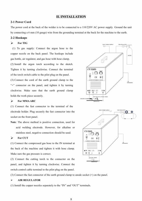
For TIG
(1) To gas supply: Connect the argon hose to the
copper nozzle on the back panel. The hookups include
gas bottle, air regulator, and gas hose with hose clamp.
(2) Install the argon torch according to the sketch.
Tighten it by turning clockwise. Connect the terminal
of the torch switch cable to the pilot plug on the panel.
(3) Connect the cord of the earth ground clamp to the
“+” connector on the panel, and tighten it by turning
clockwise. Make sure that the earth ground clamp
holds the work piece securely.
For MMA ARC
(1) Connect the fast connector to the terminal of the
electrode holder. Plug securely the fast connector into the
socket on the front panel.
Note: The above method is positive connection, used for
acid welding electrode. However, for alkaline or
stainless steel, negative connection should be used.
For CUT
(1) Connect the compressed gas hose to the IN terminal at
the back of the machine and tighten it with hose clamp.
Make sure the gas pressure is correct.
(2) Connect the cutting torch to the connector on the
panel, and tighten it by turning clockwise. Connect the
switch control cable terminal to the pilot plug on the panel.
(3) Connect the fast connector of the earth ground clamp to anode socket (+) on the panel.
AIR REGULATOR
(1) Install the copper nozzles separately to the “IN” and “OUT” terminals.
8

(2) Install the meter to the regulator.
(3) Fasten the regulator support rack to the back of the machine as shown in the figure.
(4) Fasten the air regulator to the support rack as shown in the figure.
(5) Air pressure is displayed in the dial.
(6) Lift the pressure adjustment knob to adjust the pressure as desired, and, when done, push the pressure
adjustment knob down.
(7) Pull the drain plug to drain the glass cup when water accumulates in it.
Note: 1) Connect argon gas supply for TIG and compressed air for CUT.
Assembly of the Torch Consumables for CUT Torch Head and TIG Torch Head is shown in the following Fig:
Assembly of Consumables for Cut Torch Head
The torch handle is made of fire and heat retarded ceramic. Do not drop the torch or strike anything with it. The
On/Off switch can be positioned on the top, side or bottom of the torch body to allow ease of use. Insert the
electrode in, seat the ring on the electrode, and place the copper on the ring nice and flat. Then, secure all the
parts in place by turning the ceramic cup clockwise until it is snug. Do not over-tighten it and make sure the tip
is placed properly under the cup.
9
Nozzle
Ceramic Cup
Swirl Ring
Electrode
Switch On/Off
Cup Seat
Torch Body

Assembly of Consumables for TIG Torch Head
The panel of CT series welder is shown in the following figure:
FRONT PANEL
Connect fast connector of the earth ground clamp to EARTH INTERFACE before beginning to weld or cut;
Welding or cutting amperage can be adjusted during operation by turning CURRENT REGULATOR;
Post-gas will protect work piece by maintaining compressed air from torch to cool the welding point. The
duration of post-gas can be adjusted by rotating the knob of POST-GAS REGULATOR;
For ARC/MMA welder, connect fast connector of electrode holder to ARC HOLDER INTERFACE;
For TIG welder, connect TIG torch to TIG/CUT TORCH INTERFACE, and connect pilot plug to TORCH
SWITCH INTERFACE;
For plasma cutting, connect CUT torch to TIG/CUT TORCH INTERFACE, and connect pilot plug to
TORCH SWITCH INTERFACE.
10

III. OPERATION
3-1 TIG
(1) Turn the power switch on the panel to “ON”, and the pilot light and the fan will come on.
(2) Set the operation mode switch to the TIG position.
(3) Turn on the argon gas switch, and set gas flow/pressure at desired level.
(4) Push down the button on the torch, and the electromagnetic valve will begin to work. The sound of HF arc-
striking will be heard, and, at the same time, gas is flowing out of the torch nozzle.
Note: When starting a new session of use, press the button on the torch for a few seconds to completely fill the
hose with argon gas and purge out air before beginning to weld. After welding is stopped, the post-gas output
will continue and the argon gas will still be coming out for several seconds. This is specially designed for
protecting the welding point from being oxidized before cooling. Please keep the torch at the welding point for
a while after the arc is extinguished.
(5) Set welding amperage at a desired level according to the thickness of the work piece and the technical
requirements.
(6) Keep the tungsten 1-4 mm away from the work piece, press down the control button of the torch, and there
will be HF arc generated between the electrode and the work piece. Start welding after the arc disappears.
3-2 MMA ARC
Set the operation mode switch to “Welding” position, turn the power switch on, and the pilot light and the fan
will come on. According to thickness of the work-piece, select desired welding amperage and welding
electrode, and start to weld.
3-3 CUT
Set the operation mode switch to “CUT” position, turn the power switch on, and the pilot light and the fan will
come on. Set the air pressure at a desired level, press down the switch button on the cutting torch, and the
sound of HF arc-striking will be heard, and, at the same time, the compressed gas will flow out of the torch
nozzle. Set cutting amperage according to the thickness of the work-piece. Let the nozzle touch the work-piece,
and the plasma arc will start while the sound of HF arc-striking disappears. Now, you are ready to begin your
work. After the arc starts, keep the nozzle 1 mm away from the work-piece to protect the nozzle.
Note: If the output voltage cannot start arc-striking, please turn the air pressure a little lower. If the arc-striking
generated is too strong, please turn the air pressure a little higher.
11

IV. CAUTIONS
4-1 Working Environment
(1) The location where this machine is placed should be of little dust and no corrosive chemical gases or
flammable gases and materials, with maximum moisture of no more than 80%;
(2) Do not operate this machine in the open air unless the working area is sheltered from the sunshine, rain,
water, snow, etc. The temperature of the working area should be kept between -10C to +50C;
(3) Keep this machine at least 30 cm (1 foot) away from the wall or obstacles;
(4) The working area should be well ventilated, use a fan if necessary.
4-2 Safety Tips
(1) Ventilation
This machine is small in size, compact in structure, and large in amperage output. The fans are only to extract
heat generated by its internal electronics. Therefore, the working area should be well ventilated and proper
protection should be used.
Cautions:Make sure the louvers (vents) on the equipment are always clear of obstructions. Good ventilation
is critical for the proper performance and service life of this machine.
(2) O.C. Over-load
When over-load happens, a sudden halt will occur in cutting or welding and the O.C. (over current) light will
come on. In this case, simply stop welding. Do not turn off the machine or restart it either. Leave the unit ON
and allow the internal fans to cool down the temperature inside the equipment. Resume work when the O.C.
light turns off.
(3) Over-voltage
For the range of the power voltage for this machine, please refer to the "Specifications" table on page 6. This
machine has automatic voltage compensation in the power supply, which allows it to operate within the given
ranges listed in the table. In case that the voltage exceeds the stipulated value, the over voltage may damage the
components of this equipment.
(4) Grounding
An earth ground terminal is supplied with the machine and should be used. Connect the earth grounding cable
to avoid static and electric shock.
(5) Never make contact with the output terminals (torch and ground) during operation as electric shock may
occur.
12

V. MAINTENANCE
(1) Clear the dust at regular intervals with clean and dry compressed air. Set the air flow at a reasonable
pressure to avoid damaging small parts in the machine. If the working area is dusty, damp and heavy in
smoke or corrosive gases, this machine should be cleaned at least once a month.
(2) Periodically check the inner gas/electric connections. Tighten any found loose connections. If connections
are oxidized, disconnect and clean them with sand paper and then re-connect them.
(3) Keep the machine away from water and rain. If the machine gets damp, dry it in time, and check all the
insulation in the machine with a mega meter.
(4) If the machine is expected to be out of service for a long period of time, put it away in the original
packing in a dry area
(5) Be careful not to drop the torches as the ceramic cups may crack or break.
13
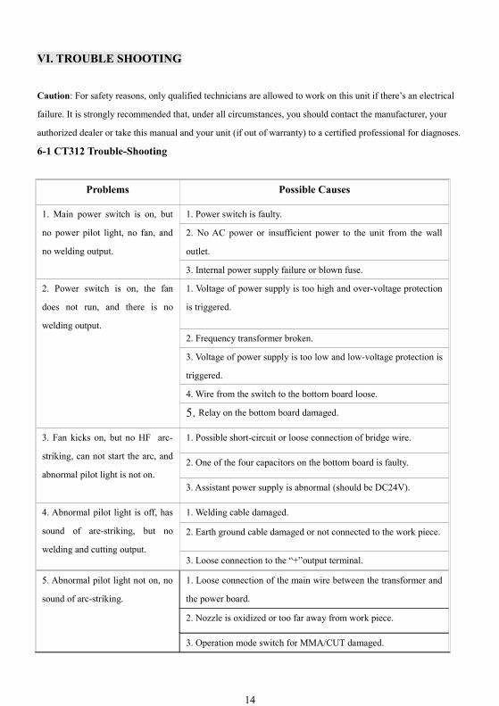
VI. TROUBLE SHOOTING
Caution: For safety reasons, only qualified technicians are allowed to work on this unit if there’s an electrical
failure. It is strongly recommended that, under all circumstances, you should contact the manufacturer, your
authorized dealer or take this manual and your unit (if out of warranty) to a certified professional for diagnoses.
6-1 CT312 Trouble-Shooting
Problems Possible Causes
1. Main power switch is on, but
no power pilot light, no fan, and
no welding output.
1. Power switch is faulty.
2. No AC power or insufficient power to the unit from the wall
outlet.
3. Internal power supply failure or blown fuse.
2. Power switch is on, the fan
does not run, and there is no
welding output.
1. Voltage of power supply is too high and over-voltage protection
is triggered.
2. Frequency transformer broken.
3. Voltage of power supply is too low and low-voltage protection is
triggered.
4. Wire from the switch to the bottom board loose.
5. Relay on the bottom board damaged.
3. Fan kicks on, but no HF arc-
striking, can not start the arc, and
abnormal pilot light is not on.
1. Possible short-circuit or loose connection of bridge wire.
2. One of the four capacitors on the bottom board is faulty.
3. Assistant power supply is abnormal (should be DC24V).
4. Abnormal pilot light is off, has
sound of are-striking, but no
welding and cutting output.
1. Welding cable damaged.
2. Earth ground cable damaged or not connected to the work piece.
3. Loose connection to the “+”output terminal.
5. Abnormal pilot light not on, no
sound of arc-striking.
1. Loose connection of the main wire between the transformer and
the power board.
2. Nozzle is oxidized or too far away from work piece.
3. Operation mode switch for MMA/CUT damaged.
14
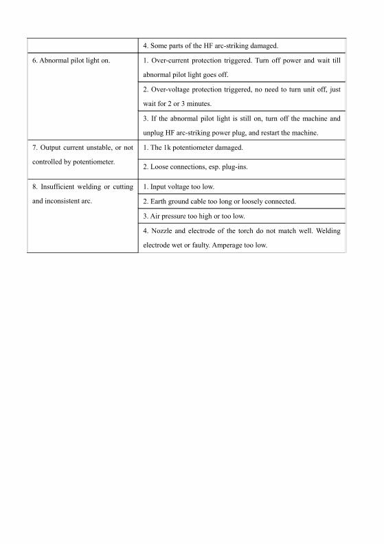
4. Some parts of the HF arc-striking damaged.
6. Abnormal pilot light on. 1. Over-current protection triggered. Turn off power and wait till
abnormal pilot light goes off.
2. Over-voltage protection triggered, no need to turn unit off, just
wait for 2 or 3 minutes.
3. If the abnormal pilot light is still on, turn off the machine and
unplug HF arc-striking power plug, and restart the machine.
7. Output current unstable, or not
controlled by potentiometer.
1. The 1k potentiometer damaged.
2. Loose connections, esp. plug-ins.
8. Insufficient welding or cutting
and inconsistent arc.
1. Input voltage too low.
2. Earth ground cable too long or loosely connected.
3. Air pressure too high or too low.
4. Nozzle and electrode of the torch do not match well. Welding
electrode wet or faulty. Amperage too low.
15


