139
OPERATION MANUAL DAKOTA ULTRASONICS DFX-7 Ultrasonic Flaw Detector (Manual 2 of 2) P/N P-220-0002 Rev 1.0, June 2011
OPERATION MANUAL
DAKOTA ULTRASONICS
DDFFXX--77 Ultrasonic Flaw Detector
(Manual 2 of 2)
P/N P-220-0002 Rev 1.0, June 2011


CHAPTER ONE INTRODUCTION ...................................................................... 1
CHAPTER TWO QUICK START GUIDE ............................................................ 3
CHAPTER THREE KEYBOARD, MENU, & CONNECTOR REFERENCE ......... 7
CHAPTER FOUR SETTING UP FOR MEASUREMENT .................................. 23
CHAPTER FIVE CALIBRATION ....................................................................... 35
CHAPTER SIX TRIGONOMETRY MODE ........................................................ 50
CHAPTER SEVEN AWS – WELD INSPECTION ............................................. 55
CHAPTER EIGHT DISTANCE AMPLITUDE CORRECTION (DAC) ................ 60
CHAPTER NINE TIME CORRECTED GAIN (TCG) ......................................... 66
CHAPTER TEN ADDITIONAL FEATURES OF THE DFX-7 ............................. 71
CHAPTER ELEVEN DATA STORAGE – SETUP, EDIT, & VIEW FILES ......... 95
CHAPTER TWELVE SETUPS – CREATE, STORE, EDIT, & RECALL ......... 120
CHAPTER THIRTEEN USING THE UTILITY SOFTWARE ............................ 130
APPENDIX A - VELOCITY TABLE ................................................................. 132
APPENDIX B - SETUP LIBRARY ................................................................... 134

CHAPTER ONE INTRODUCTION
The Dakota Ultrasonics model DFX-7 is both, an ultrasonic flaw detector, as well as an ultrasonic A/B Scan thickness scope, in a single unit. It’s a combination of both our CMX DL+, as well as our new DFX-7 flaw detector series. Why is this advantageous? Thickness gauge are specifically setup to very accurately measure thickness, locate pits, flaws and blind surface corrosion. All the linearity tables, correction curves for various types of longitudinal transducers and features are built with dimensional thickness as its primary focus. Flaw detectors are designed to detect, size, position, and differentiate between flaw types in various materials and welded joints. A flaw detector must be fast, in terms of its sample and screen refresh rate, as inspectors are generally scanning the surface of a part or test specimen at a relatively high speed, rather than looking for the thickness at a specific point or location. While flaw detectors can also measure material thickness with reasonable accuracy, they are not designed with precision thickness as their primary focus. The DFX-7 combines the two types of gauges into one powerful and full featured instrument, that’s equipped with a number of comprehensive toolkits to provide the user the arsenal necessary to address a number of common field applications. In and effort to avoid complexity issues and differential between gauges types, this manual focuses only on the flaw detector portion of the DFX-7. Dakota Ultrasonics maintains a customer support resource in order to assist users with questions or difficulties not covered in this manual. Customer support may be reached at any of the following:
Dakota Ultrasonics Corporation 1500 Green Hills Road, #107 Scotts Valley, CA 95066 USA Telephone: (831) 431-9722 Facsimile: (831) 431-9723 www.dakotaultrasonics.com
1.1 General Disclaimer The manual should be read and understood prior to using the DFX-7. This operating manual provides the user with all the general information necessary to use and operate the features of the DFX-7. However, this manual is not a certified NDT training course, nor is it intended to be one. Ultrasonic training for sound wave theory, flaw detection and interpretation of defects is highly recommended, and will be required by most companies and contract services. Contact the local NDT society in your area to inquire about training available in your locality.

1.2 Electrical Warning The DFX-7 contains a high voltage pulser. It’s recommended that the gauge be powered off prior to connecting or disconnecting your transducer, to avoid damaging the DFX-7.
3
CHAPTER TWO QUICK START GUIDE
This section will cover a basic quick start guide to initially get up and running with the DFX-7 for demonstration purposes only. However, in order to use the gauge and features for actual applications, a thorough review of this manual is recommended.
2.1 Gauge Type
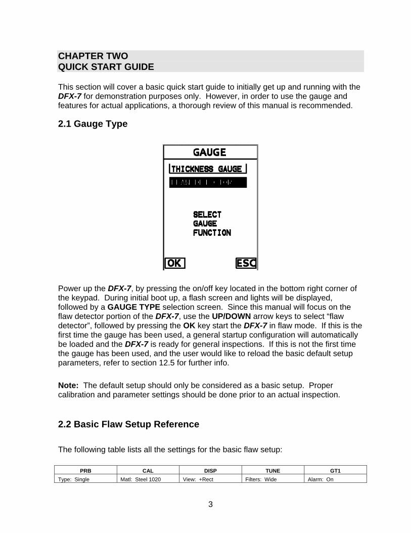
Power up the DFX-7, by pressing the on/off key located in the bottom right corner of the keypad. During initial boot up, a flash screen and lights will be displayed, followed by a GAUGE TYPE selection screen. Since this manual will focus on the flaw detector portion of the DFX-7, use the UP/DOWN arrow keys to select “flaw detector”, followed by pressing the OK key start the DFX-7 in flaw mode. If this is the first time the gauge has been used, a general startup configuration will automatically be loaded and the DFX-7 is ready for general inspections. If this is not the first time the gauge has been used, and the user would like to reload the basic default setup parameters, refer to section 12.5 for further info. Note: The default setup should only be considered as a basic setup. Proper calibration and parameter settings should be done prior to an actual inspection.
2.2 Basic Flaw Setup Reference The following table lists all the settings for the basic flaw setup:
PRB CAL DISP TUNE GT1 Type: Single Matl: Steel 1020 View: +Rect Filters: Wide Alarm: On

Dakota Ultrasonics
4
Pulse: Thin Matl 1pt: Uncal Delay: 0.000 Gain: 65 Gate1: 0.484 Max PRF: 66 Matl 2pt: Uncal Range: 5.011 Detect Mode: Z-Cross Thresh1: 40% Damping: 600 Velocity: .2320 Units: inches Width1: INF Pulser Volt: 200 Zero: 0.0 Brightness: 15 Detect: Above View: Green 1 Polarity: Pos Dim: Off Rect Wave: Filled Detect Mark: None
Note: The following features are set to off: GT2, TRIG, AWS, TCG, DAC, DGS.
2.3 Top & Submenu Reference The following table is a quick menu reference guide. The DFX-7 has 15 top level menu titles, and multiple submenu items as illustrated below. Refer to Chapter Three for additional definitions and information on the keypad and menu items. Start >>
PRB CAL DISP TUNE GT1 GT2 TRIG AWS
TYPE MAT VIEW FILTERS ALARM ALARM TRIG AWS
PULSE MATL 1PT DELAY MAX PRF DETECT DETECT THICKNESS SET REF GAIN
DAMPING MATL 2PT RANGE GAIN GATE1 GATE2 ANGLE % SCRN
HEIGHT
PULSER
VOLTAGE
VELOCITY UNITS DETECT MODE GATE1 WIDTH GATE2 WIDTH X-OFFSET
ZERO BRIGHTNESS THRESHOLD1 THRESHOLD2
COLORS POLARITY1 POLARITY1
DIM
RECT WAVE
DETECT MARK
>> End
TCG DAC DGS SET DATA UTIL XFER
TCG DAC DGS OPEN NEW AUTO FIND BACKUP
SETUPS
DRAW DRAW PROBE
CONFIG
SAVE EDIT GAUGE RESTORE
SETUPS
CURVE MEAS TRANS LOSS DELETE ONE OPEN BACKUP DATA
DFX-7 Ultrasonic Flaw Detector
5
FILE
% SCRN
HEIGHT
CURVE REFLECT
LOSS
DEFAULT
SETUP
CLOSE RESTORE
DATA
TRIGGER MATERIAL
LOSS
LANGUAGE DELETE ONE
FILE
ABOUT
DPOLARITY TB VELOCITY DELETE ALL
DATA
TB TYPE
TB SIZE
SIGNAL
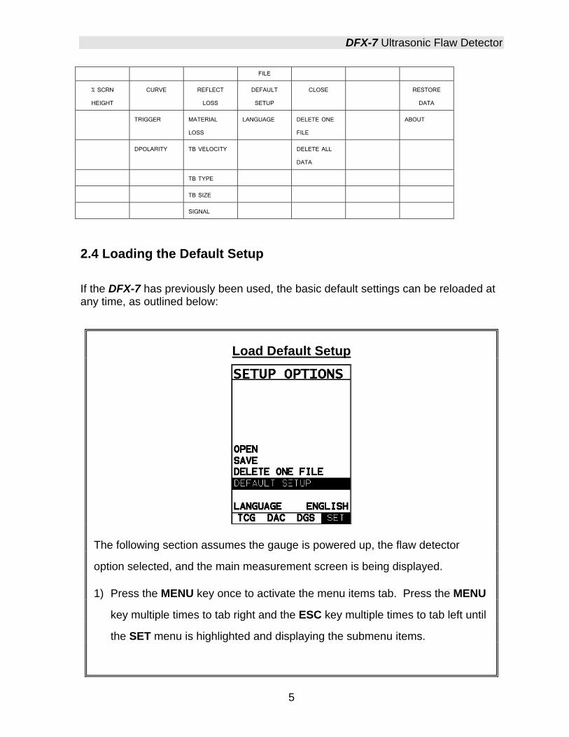
2.4 Loading the Default Setup If the DFX-7 has previously been used, the basic default settings can be reloaded at any time, as outlined below:
Load Default Setup
The following section assumes the gauge is powered up, the flaw detector
option selected, and the main measurement screen is being displayed.
1) Press the MENU key once to activate the menu items tab. Press the MENU
key multiple times to tab right and the ESC key multiple times to tab left until
the SET menu is highlighted and displaying the submenu items.
Dakota Ultrasonics
6
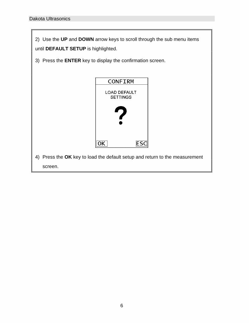
2) Use the UP and DOWN arrow keys to scroll through the sub menu items
until DEFAULT SETUP is highlighted.
3) Press the ENTER key to display the confirmation screen.
4) Press the OK key to load the default setup and return to the measurement
screen.
7
CHAPTER THREE KEYBOARD, MENU, & CONNECTOR REFERENCE
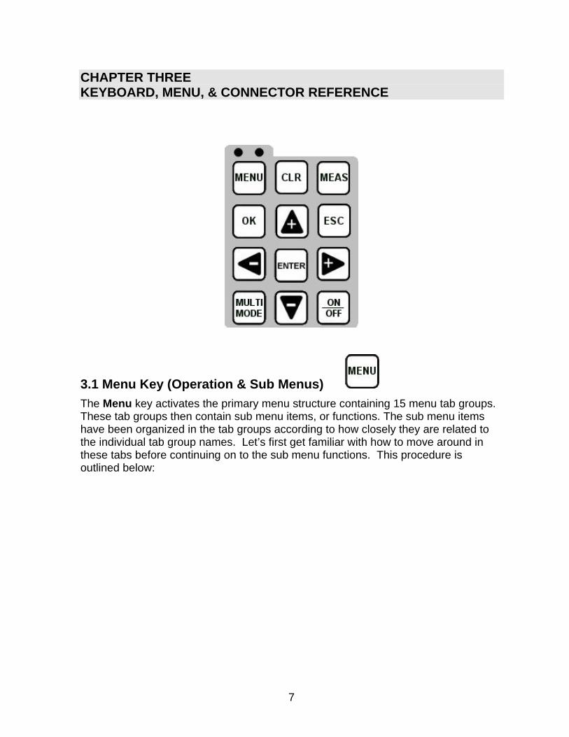
3.1 Menu Key (Operation & Sub Menus) The Menu key activates the primary menu structure containing 15 menu tab groups. These tab groups then contain sub menu items, or functions. The sub menu items have been organized in the tab groups according to how closely they are related to the individual tab group names. Let’s first get familiar with how to move around in these tabs before continuing on to the sub menu functions. This procedure is outlined below:

Dakota Ultrasonics
8
Activating and Navigation of the Menu Items
1) Press the MENU key once to activate the menu items tab. Press the MENU
key multiple times to tab right, and the ESC key multiple times to tab left
until the desired tab group is highlighted and displaying the submenu items.
The tab groups are illustrated above (A).
Now that you’re familiar with activating and moving amongst the tab groups,
let’s have a look at how to move around in the sub menu items as follows:
2) Use the UP and DOWN arrow keys to scroll through the sub menu items
until the desired function is highlighted. The sub menu items are illustrated
in the diagram above (B).
3) Depending on which function is highlighted, use the LEFT, RIGHT, and
Enter keys to scroll the options or activate the Digit Edit and List Box
options.
The sections to follow will provide the user with an explanation of the sub menu functions:
DFX-7 Ultrasonic Flaw Detector
9
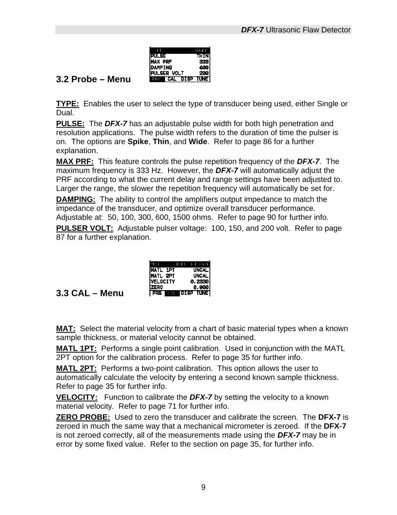
3.2 Probe – Menu TYPE: Enables the user to select the type of transducer being used, either Single or Dual. PULSE: The DFX-7 has an adjustable pulse width for both high penetration and resolution applications. The pulse width refers to the duration of time the pulser is on. The options are Spike, Thin, and Wide. Refer to page 86 for a further explanation. MAX PRF: This feature controls the pulse repetition frequency of the DFX-7. The maximum frequency is 333 Hz. However, the DFX-7 will automatically adjust the PRF according to what the current delay and range settings have been adjusted to. Larger the range, the slower the repetition frequency will automatically be set for. DAMPING: The ability to control the amplifiers output impedance to match the impedance of the transducer, and optimize overall transducer performance. Adjustable at: 50, 100, 300, 600, 1500 ohms. Refer to page 90 for further info. PULSER VOLT: Adjustable pulser voltage: 100, 150, and 200 volt. Refer to page 87 for a further explanation.
3.3 CAL – Menu MAT: Select the material velocity from a chart of basic material types when a known sample thickness, or material velocity cannot be obtained. MATL 1PT: Performs a single point calibration. Used in conjunction with the MATL 2PT option for the calibration process. Refer to page 35 for further info. MATL 2PT: Performs a two-point calibration. This option allows the user to automatically calculate the velocity by entering a second known sample thickness. Refer to page 35 for further info. VELOCITY: Function to calibrate the DFX-7 by setting the velocity to a known material velocity. Refer to page 71 for further info. ZERO PROBE: Used to zero the transducer and calibrate the screen. The DFX-7 is zeroed in much the same way that a mechanical micrometer is zeroed. If the DFX-7 is not zeroed correctly, all of the measurements made using the DFX-7 may be in error by some fixed value. Refer to the section on page 35, for further info.
Dakota Ultrasonics
10
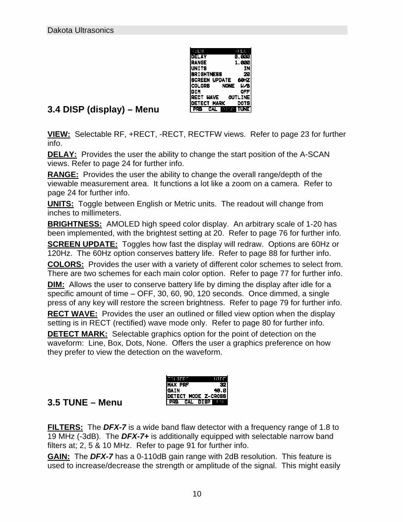
3.4 DISP (display) – Menu VIEW: Selectable RF, +RECT, -RECT, RECTFW views. Refer to page 23 for further info. DELAY: Provides the user the ability to change the start position of the A-SCAN views. Refer to page 24 for further info. RANGE: Provides the user the ability to change the overall range/depth of the viewable measurement area. It functions a lot like a zoom on a camera. Refer to page 24 for further info. UNITS: Toggle between English or Metric units. The readout will change from inches to millimeters. BRIGHTNESS: AMOLED high speed color display. An arbitrary scale of 1-20 has been implemented, with the brightest setting at 20. Refer to page 76 for further info. SCREEN UPDATE: Toggles how fast the display will redraw. Options are 60Hz or 120Hz. The 60Hz option conserves battery life. Refer to page 88 for further info. COLORS: Provides the user with a variety of different color schemes to select from. There are two schemes for each main color option. Refer to page 77 for further info. DIM: Allows the user to conserve battery life by diming the display after idle for a specific amount of time – OFF, 30, 60, 90, 120 seconds. Once dimmed, a single press of any key will restore the screen brightness. Refer to page 79 for further info. RECT WAVE: Provides the user an outlined or filled view option when the display setting is in RECT (rectified) wave mode only. Refer to page 80 for further info. DETECT MARK: Selectable graphics option for the point of detection on the waveform: Line, Box, Dots, None. Offers the user a graphics preference on how they prefer to view the detection on the waveform.
3.5 TUNE – Menu FILTERS: The DFX-7 is a wide band flaw detector with a frequency range of 1.8 to 19 MHz (-3dB). The DFX-7+ is additionally equipped with selectable narrow band filters at; 2, 5 & 10 MHz. Refer to page 91 for further info. GAIN: The DFX-7 has a 0-110dB gain range with 2dB resolution. This feature is used to increase/decrease the strength or amplitude of the signal. This might easily
DFX-7 Ultrasonic Flaw Detector
11
be considered as similar to turning the volume up or down on a stereo receiver. Refer to page 27 for further info. DETECT MODE: The DFX-7 is equipped with optional detection modes; PEAK, FLANK, or Z-CROSS (zero crossing). This options allows the user to decide where the detection is acquired on the waveform echo. Refer to page 84 for further info.
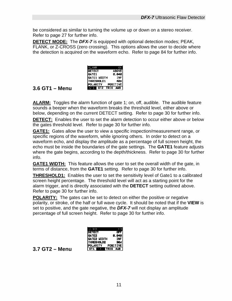
3.6 GT1 – Menu ALARM: Toggles the alarm function of gate 1; on, off, audible. The audible feature sounds a beeper when the waveform breaks the threshold level, either above or below, depending on the current DETECT setting. Refer to page 30 for further info. DETECT: Enables the user to set the alarm detection to occur either above or below the gates threshold level. Refer to page 30 for further info. GATE1: Gates allow the user to view a specific inspection/measurement range, or specific regions of the waveform, while ignoring others. In order to detect on a waveform echo, and display the amplitude as a percentage of full screen height, the echo must be inside the boundaries of the gate settings. The GATE1 feature adjusts where the gate begins, according to the depth/thickness. Refer to page 30 for further info. GATE1 WIDTH: This feature allows the user to set the overall width of the gate, in terms of distance, from the GATE1 setting. Refer to page 30 for further info. THRESHOLD1: Enables the user to set the sensitivity level of Gate1 to a calibrated screen height percentage. The threshold level will act as a starting point for the alarm trigger, and is directly associated with the DETECT setting outlined above. Refer to page 30 for further info. POLARITY: The gates can be set to detect on either the positive or negative polarity, or stroke, of the half or full wave cycle. It should be noted that if the VIEW is set to positive, and the gate negative, the DFX-7 will not display an amplitude percentage of full screen height. Refer to page 30 for further info.
3.7 GT2 – Menu
Dakota Ultrasonics
12
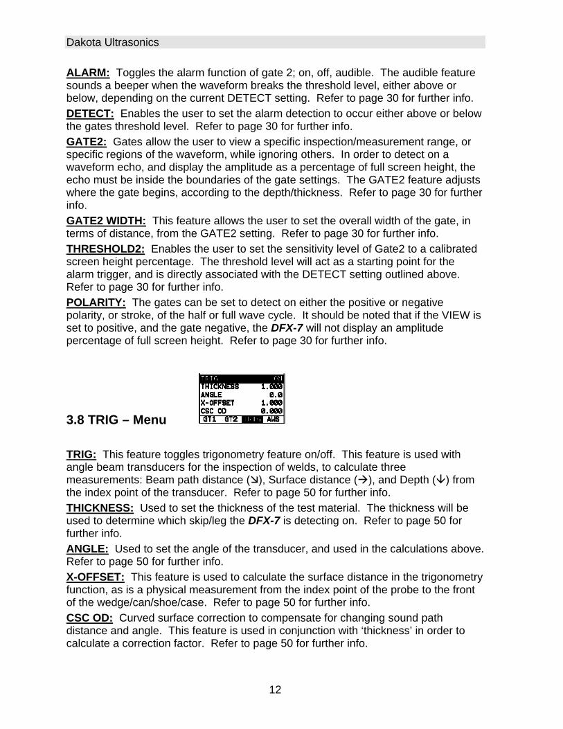
ALARM: Toggles the alarm function of gate 2; on, off, audible. The audible feature sounds a beeper when the waveform breaks the threshold level, either above or below, depending on the current DETECT setting. Refer to page 30 for further info. DETECT: Enables the user to set the alarm detection to occur either above or below the gates threshold level. Refer to page 30 for further info. GATE2: Gates allow the user to view a specific inspection/measurement range, or specific regions of the waveform, while ignoring others. In order to detect on a waveform echo, and display the amplitude as a percentage of full screen height, the echo must be inside the boundaries of the gate settings. The GATE2 feature adjusts where the gate begins, according to the depth/thickness. Refer to page 30 for further info. GATE2 WIDTH: This feature allows the user to set the overall width of the gate, in terms of distance, from the GATE2 setting. Refer to page 30 for further info. THRESHOLD2: Enables the user to set the sensitivity level of Gate2 to a calibrated screen height percentage. The threshold level will act as a starting point for the alarm trigger, and is directly associated with the DETECT setting outlined above. Refer to page 30 for further info. POLARITY: The gates can be set to detect on either the positive or negative polarity, or stroke, of the half or full wave cycle. It should be noted that if the VIEW is set to positive, and the gate negative, the DFX-7 will not display an amplitude percentage of full screen height. Refer to page 30 for further info.
3.8 TRIG – Menu TRIG: This feature toggles trigonometry feature on/off. This feature is used with angle beam transducers for the inspection of welds, to calculate three measurements: Beam path distance ( ), Surface distance ( ), and Depth ( ) from the index point of the transducer. Refer to page 50 for further info. THICKNESS: Used to set the thickness of the test material. The thickness will be used to determine which skip/leg the DFX-7 is detecting on. Refer to page 50 for further info. ANGLE: Used to set the angle of the transducer, and used in the calculations above. Refer to page 50 for further info. X-OFFSET: This feature is used to calculate the surface distance in the trigonometry function, as is a physical measurement from the index point of the probe to the front of the wedge/can/shoe/case. Refer to page 50 for further info. CSC OD: Curved surface correction to compensate for changing sound path distance and angle. This feature is used in conjunction with ‘thickness’ in order to calculate a correction factor. Refer to page 50 for further info.
DFX-7 Ultrasonic Flaw Detector
13
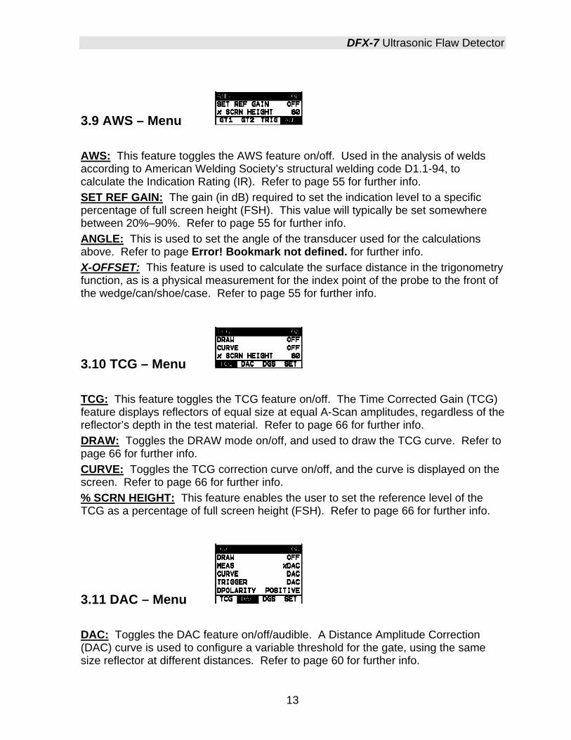
3.9 AWS – Menu AWS: This feature toggles the AWS feature on/off. Used in the analysis of welds according to American Welding Society’s structural welding code D1.1-94, to calculate the Indication Rating (IR). Refer to page 55 for further info. SET REF GAIN: The gain (in dB) required to set the indication level to a specific percentage of full screen height (FSH). This value will typically be set somewhere between 20%–90%. Refer to page 55 for further info. ANGLE: This is used to set the angle of the transducer used for the calculations above. Refer to page Error! Bookmark not defined. for further info. X-OFFSET: This feature is used to calculate the surface distance in the trigonometry function, as is a physical measurement for the index point of the probe to the front of the wedge/can/shoe/case. Refer to page 55 for further info.
3.10 TCG – Menu TCG: This feature toggles the TCG feature on/off. The Time Corrected Gain (TCG) feature displays reflectors of equal size at equal A-Scan amplitudes, regardless of the reflector’s depth in the test material. Refer to page 66 for further info. DRAW: Toggles the DRAW mode on/off, and used to draw the TCG curve. Refer to page 66 for further info. CURVE: Toggles the TCG correction curve on/off, and the curve is displayed on the screen. Refer to page 66 for further info. % SCRN HEIGHT: This feature enables the user to set the reference level of the TCG as a percentage of full screen height (FSH). Refer to page 66 for further info.
3.11 DAC – Menu DAC: Toggles the DAC feature on/off/audible. A Distance Amplitude Correction (DAC) curve is used to configure a variable threshold for the gate, using the same size reflector at different distances. Refer to page 60 for further info.
Dakota Ultrasonics
14
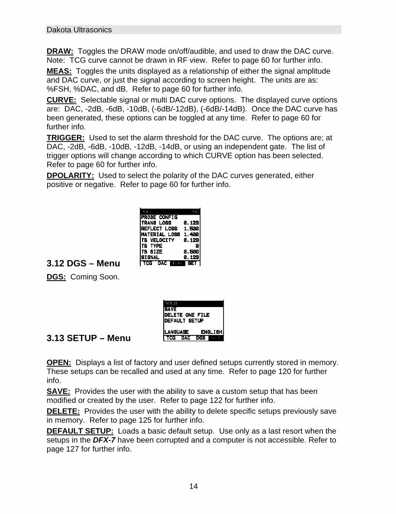
DRAW: Toggles the DRAW mode on/off/audible, and used to draw the DAC curve. Note: TCG curve cannot be drawn in RF view. Refer to page 60 for further info. MEAS: Toggles the units displayed as a relationship of either the signal amplitude and DAC curve, or just the signal according to screen height. The units are as: %FSH, %DAC, and dB. Refer to page 60 for further info. CURVE: Selectable signal or multi DAC curve options. The displayed curve options are: DAC, -2dB, -6dB, -10dB, (-6dB/-12dB), (-6dB/-14dB). Once the DAC curve has been generated, these options can be toggled at any time. Refer to page 60 for further info. TRIGGER: Used to set the alarm threshold for the DAC curve. The options are; at DAC, -2dB, -6dB, -10dB, -12dB, -14dB, or using an independent gate. The list of trigger options will change according to which CURVE option has been selected. Refer to page 60 for further info. DPOLARITY: Used to select the polarity of the DAC curves generated, either positive or negative. Refer to page 60 for further info.
3.12 DGS – Menu DGS: Coming Soon.
3.13 SETUP – Menu OPEN: Displays a list of factory and user defined setups currently stored in memory. These setups can be recalled and used at any time. Refer to page 120 for further info. SAVE: Provides the user with the ability to save a custom setup that has been modified or created by the user. Refer to page 122 for further info. DELETE: Provides the user with the ability to delete specific setups previously save in memory. Refer to page 125 for further info. DEFAULT SETUP: Loads a basic default setup. Use only as a last resort when the setups in the DFX-7 have been corrupted and a computer is not accessible. Refer to page 127 for further info.
DFX-7 Ultrasonic Flaw Detector
15
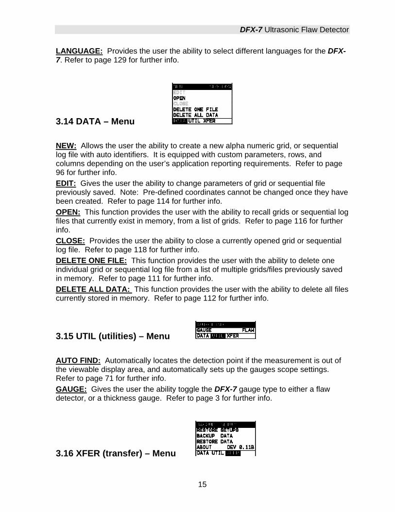
LANGUAGE: Provides the user the ability to select different languages for the DFX-7. Refer to page 129 for further info.
3.14 DATA – Menu NEW: Allows the user the ability to create a new alpha numeric grid, or sequential log file with auto identifiers. It is equipped with custom parameters, rows, and columns depending on the user’s application reporting requirements. Refer to page 96 for further info. EDIT: Gives the user the ability to change parameters of grid or sequential file previously saved. Note: Pre-defined coordinates cannot be changed once they have been created. Refer to page 114 for further info. OPEN: This function provides the user with the ability to recall grids or sequential log files that currently exist in memory, from a list of grids. Refer to page 116 for further info. CLOSE: Provides the user the ability to close a currently opened grid or sequential log file. Refer to page 118 for further info. DELETE ONE FILE: This function provides the user with the ability to delete one individual grid or sequential log file from a list of multiple grids/files previously saved in memory. Refer to page 111 for further info. DELETE ALL DATA: This function provides the user with the ability to delete all files currently stored in memory. Refer to page 112 for further info.
3.15 UTIL (utilities) – Menu AUTO FIND: Automatically locates the detection point if the measurement is out of the viewable display area, and automatically sets up the gauges scope settings. Refer to page 71 for further info. GAUGE: Gives the user the ability toggle the DFX-7 gauge type to either a flaw detector, or a thickness gauge. Refer to page 3 for further info.
3.16 XFER (transfer) – Menu

Dakota Ultrasonics
16
BACKUP SETUPS: Enables the user the ability to backup the setups currently stored in the DFX-7 to a PC via RS232 port. USB adaptor included. Refer the help section of the DFX-7 DakView software for a complete electronic manual. RESTORE SETUPS: Enables the user the ability to restore the setups currently saved on a PC to an DFX-7 via RS232 port. Refer the help section of the DFX-7 DakView software for a complete electronic manual. BACKUP DATA: Enables the user the ability to backup grids or sequential log files currently stored in the DFX-7 to a PC via RS232 port. Refer the help section of the DFX-7 DakView software for a complete electronic manual. RESTORE DATA: Enables the user the ability to restore grids or sequential log files currently saved on a PC to an DFX-7 via RS232 port. Refer the help section of the DFX-7 DakView software for a complete electronic manual. ABOUT: Provides the user with Dakota Ultrasonics contact information and the DFX-7 software version. Refer to the Dakota Ultrasonics web site for information on the latest firmware versions available for download.
3.17 CLR (clear) Key The primary functions of the CLR key, is to clear a measurement from a grid or sequential log files cell location or set obstruct, backspace in an Alpha Edit Box, or clear a DAC reference point used to generate a curve. Use this key to clear saved measurement & waveform.
3.18 MEAS (measurement mode) Key The MEAS key puts the DFX-7 into it’s primary mode of operation. In this mode, the user has a complete view of the LCD. When pressed multiple times, navigates the hot menu items.
3.19 OK Key The primary function of the OK key is confirmation of a change or selection. The OK key also toggles the Hot Menu area, while in measurement mode, to a large digits display area. If the DFX-7 is displaying a grid log, the OK key toggles an advance to row number option.

DFX-7 Ultrasonic Flaw Detector
17
3.20 ESC Key The ESC key is used in the MENU, MEAS, and EDIT functions as a back or escape function. If the DFX-7 is displaying a grid or sequential log, the OK key toggles the display options: RF, +RECT, -RECT and RECTFW views.
3.21 Arrow Keys The Arrow Keys are used to navigate through the menus, increase/decrease values, and toggle specific function keys.
3.22 ENTER key The ENTER key is used in the overall menu selection process, to activate list and edit boxes, display and save measurements/waveforms to grid or sequential file locations.
3.23 MULTI MODE Key The MULTI MODE key provides the user with a set of flaw mode options: Normal, Peak, or Freeze. The normal mode is the standard flaw detector mode. The Peak mode draws, holds, and updates the waveform for the entire duration of the inspection. The Freeze mode ‘freezes’ the current waveform on the screen, allowing the user the time to analyze the wave.
3.24 ON/OFF Key The ON/OFF key simply powers the unit either ON or OFF. Note: Unit will automatically power off when idle for 5 minutes. All current settings are automatically saved prior to powering off.
3.25 DFX-7 Overview
Dakota Ultrasonics
18
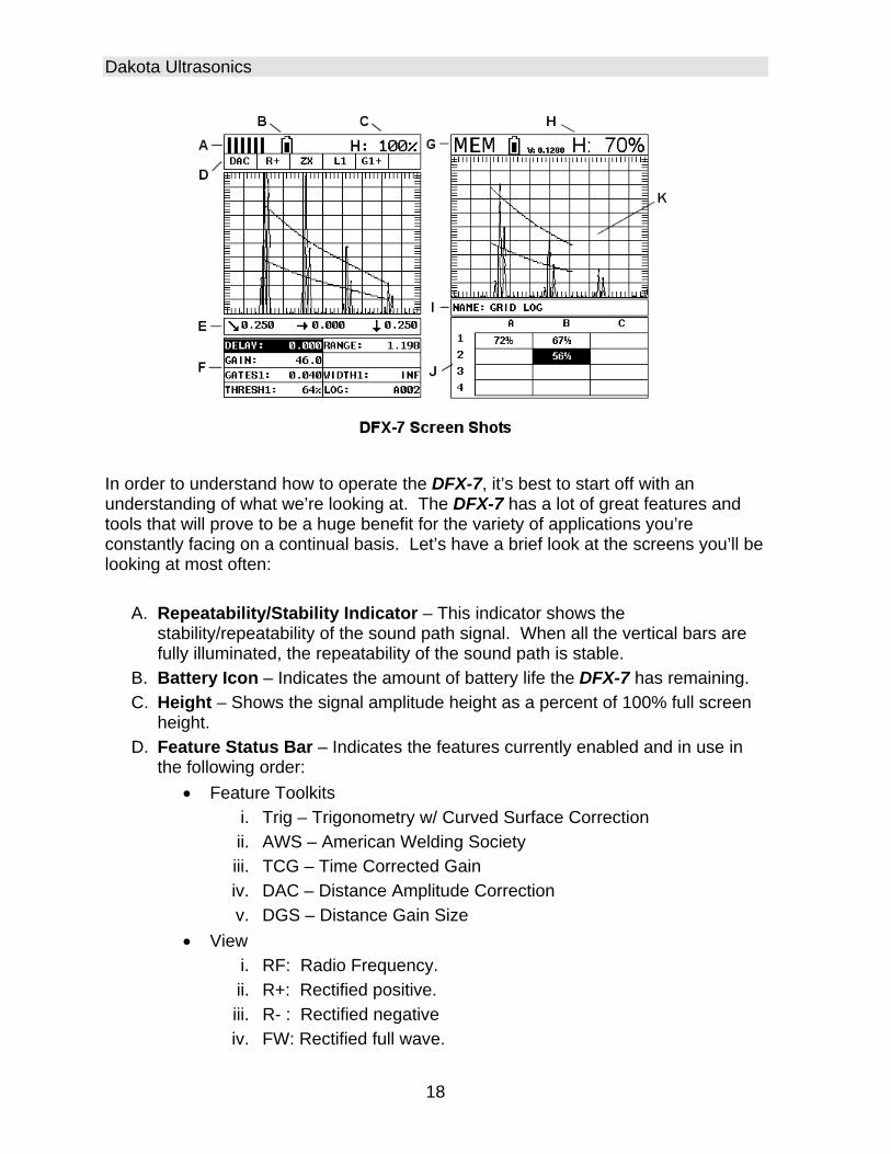
In order to understand how to operate the DFX-7, it’s best to start off with an understanding of what we’re looking at. The DFX-7 has a lot of great features and tools that will prove to be a huge benefit for the variety of applications you’re constantly facing on a continual basis. Let’s have a brief look at the screens you’ll be looking at most often:
A. Repeatability/Stability Indicator – This indicator shows the stability/repeatability of the sound path signal. When all the vertical bars are fully illuminated, the repeatability of the sound path is stable.
B. Battery Icon – Indicates the amount of battery life the DFX-7 has remaining. C. Height – Shows the signal amplitude height as a percent of 100% full screen
height. D. Feature Status Bar – Indicates the features currently enabled and in use in
the following order: • Feature Toolkits
i. Trig – Trigonometry w/ Curved Surface Correction ii. AWS – American Welding Society iii. TCG – Time Corrected Gain iv. DAC – Distance Amplitude Correction v. DGS – Distance Gain Size
• View i. RF: Radio Frequency. ii. R+: Rectified positive. iii. R- : Rectified negative iv. FW: Rectified full wave.
DFX-7 Ultrasonic Flaw Detector
19
• Detect i. Zero crossing (ZX) ii. Flank (FK) iii. Peak (PK)
• Leg – Skip leg reference, (L1…L4…) • High Speed Scan Mode • Alarm Mode • Gain Setting
E. Leg (skip leg) – Indicates which skip/leg the detection in on. The thickness of the material is used to calculate the leg.
F. Hot Menu items – We call this menu section our “hot menu”, as these items are the most commonly adjusted features, requiring quick access from the user. They can be displayed and scrolled by pressing the MEAS key at anytime. The ESC key is used in conjunction with MEAS key to reverse the direction scrolled.
G. Memory – Indicates that the currently displayed measurement screen and values have been previous stored in memory. When MEM is displayed, all measurement functions are disabled until the user advances to an empty storage location, or the current measurement is cleared by pressing the CLR key.
H. Height – Displays the amplitude of the signal as a percentage of full screen height. Depending on the quantity selected, this could also be displayed in dB, or D.
I. Grid or Seq Log Name – References the name of the log file currently open. J. Log File – Shows the storage cells of the current log file open. Depending on
the quantity currently selected, show either the %height or dB value stored. K. A-Scan Display – The actual echo reflections returned from the backwall or
defect.
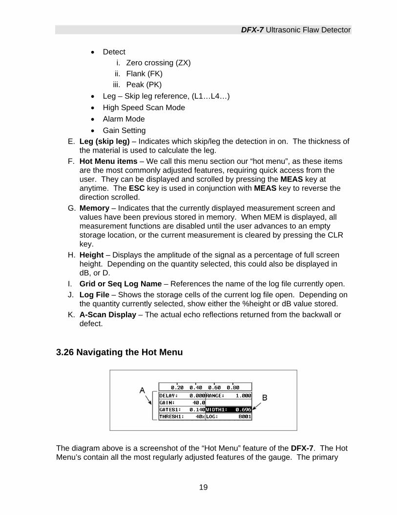
3.26 Navigating the Hot Menu
The diagram above is a screenshot of the “Hot Menu” feature of the DFX-7. The Hot Menu’s contain all the most regularly adjusted features of the gauge. The primary
Dakota Ultrasonics
20
purpose of the design, was to provide the user with an efficient way to make adjustments on the fly during inspections. The following procedure outlines the steps to navigate and make adjustments as follows:
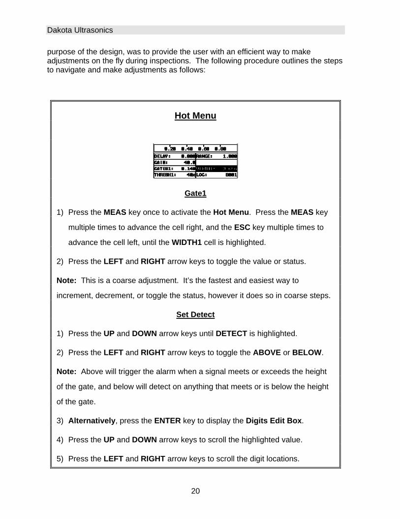
Hot Menu
Gate1
1) Press the MEAS key once to activate the Hot Menu. Press the MEAS key
multiple times to advance the cell right, and the ESC key multiple times to
advance the cell left, until the WIDTH1 cell is highlighted.
2) Press the LEFT and RIGHT arrow keys to toggle the value or status.
Note: This is a coarse adjustment. It’s the fastest and easiest way to
increment, decrement, or toggle the status, however it does so in coarse steps.
Set Detect
1) Press the UP and DOWN arrow keys until DETECT is highlighted.
2) Press the LEFT and RIGHT arrow keys to toggle the ABOVE or BELOW.
Note: Above will trigger the alarm when a signal meets or exceeds the height
of the gate, and below will detect on anything that meets or is below the height
of the gate.
3) Alternatively, press the ENTER key to display the Digits Edit Box.
4) Press the UP and DOWN arrow keys to scroll the highlighted value.
5) Press the LEFT and RIGHT arrow keys to scroll the digit locations.
DFX-7 Ultrasonic Flaw Detector
21
6) Repeat steps 4 & 5 until the start position is correctly displayed.
7) Press the OK key to set the WIDTH1 position and return to the menu
screen, or ESC to cancel entering the WIDTH1 position.
Note: This procedure is universal for all the features in the Hot Menu cell
locations.
3.27 Top & Bottom End Caps
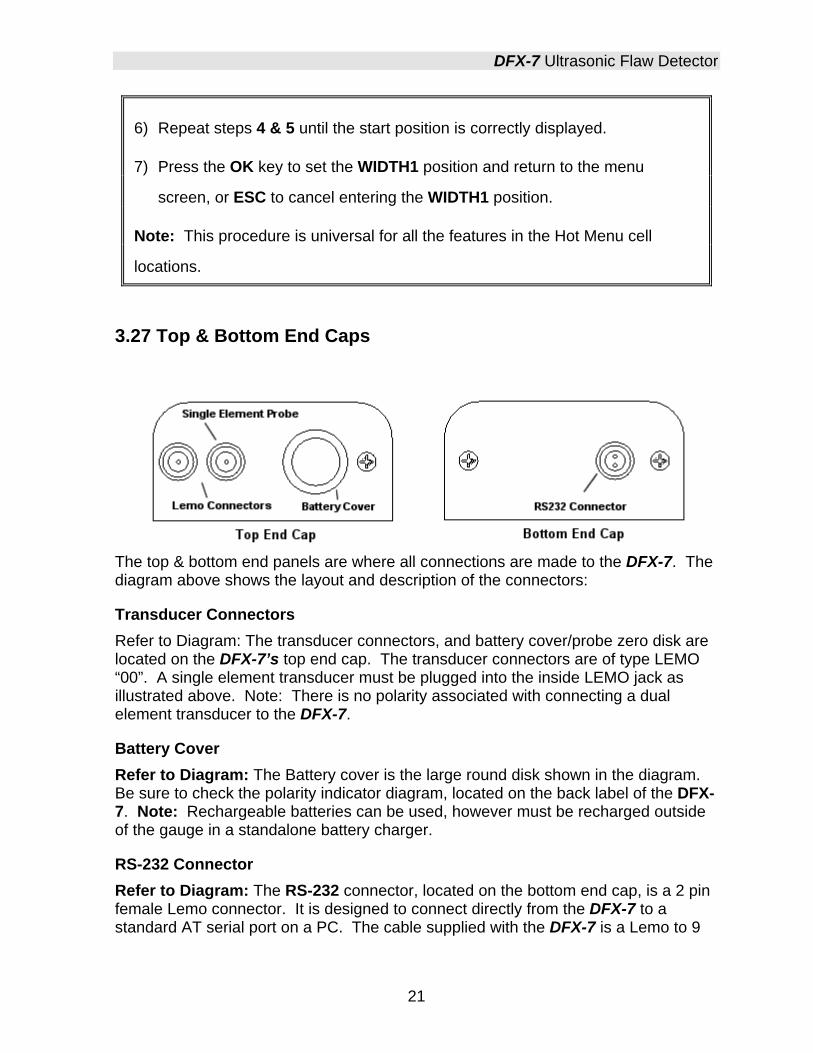
The top & bottom end panels are where all connections are made to the DFX-7. The diagram above shows the layout and description of the connectors:
Transducer Connectors Refer to Diagram: The transducer connectors, and battery cover/probe zero disk are located on the DFX-7’s top end cap. The transducer connectors are of type LEMO “00”. A single element transducer must be plugged into the inside LEMO jack as illustrated above. Note: There is no polarity associated with connecting a dual element transducer to the DFX-7.
Battery Cover Refer to Diagram: The Battery cover is the large round disk shown in the diagram. Be sure to check the polarity indicator diagram, located on the back label of the DFX-7. Note: Rechargeable batteries can be used, however must be recharged outside of the gauge in a standalone battery charger.
RS-232 Connector Refer to Diagram: The RS-232 connector, located on the bottom end cap, is a 2 pin female Lemo connector. It is designed to connect directly from the DFX-7 to a standard AT serial port on a PC. The cable supplied with the DFX-7 is a Lemo to 9
Dakota Ultrasonics
22
pin serial cable. Note: This connector is also used to upgrade the DFX-7 with the latest version of firmware.
USB Serial to USB Converter Cable A converter cable can be attached to the 9 pin serial cable in needed (part no. N-402-0510).
23
CHAPTER FOUR SETTING UP FOR MEASUREMENT
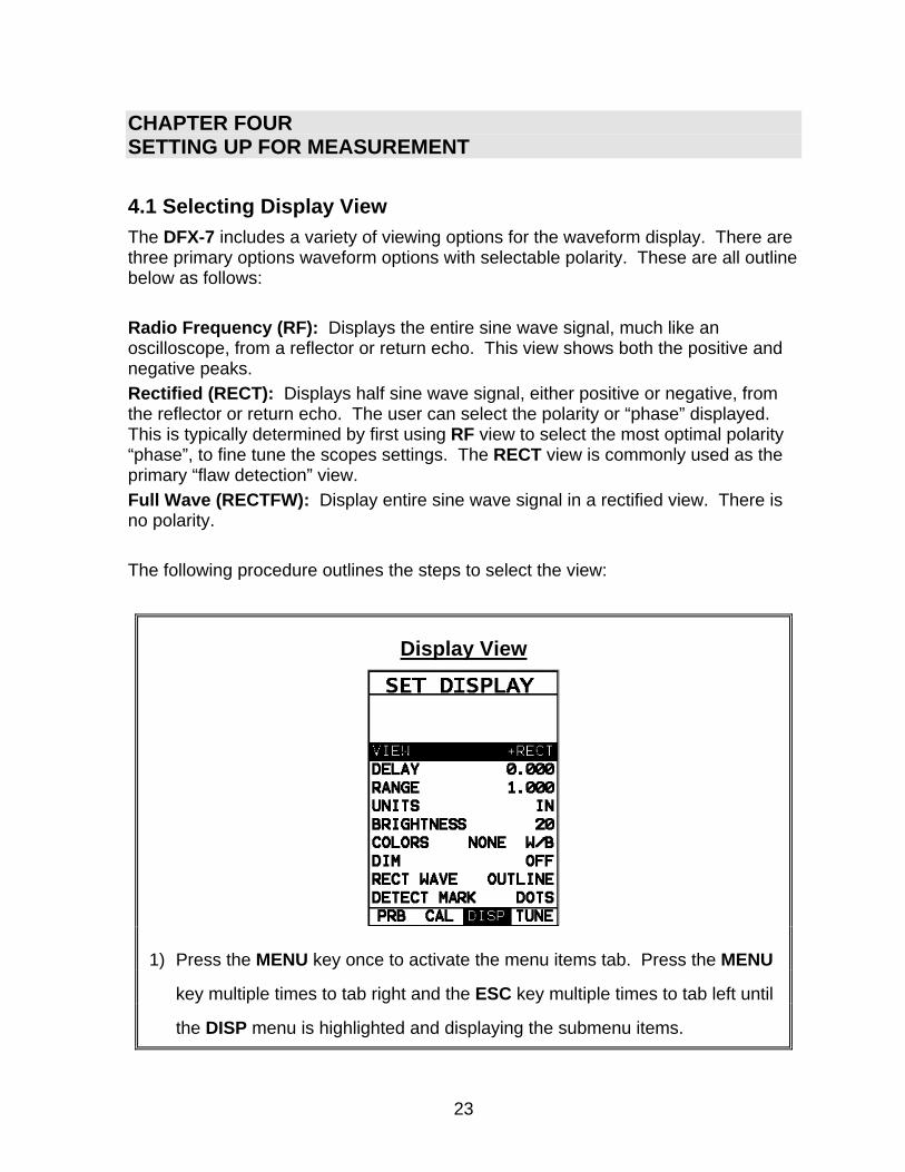
4.1 Selecting Display View The DFX-7 includes a variety of viewing options for the waveform display. There are three primary options waveform options with selectable polarity. These are all outline below as follows: Radio Frequency (RF): Displays the entire sine wave signal, much like an oscilloscope, from a reflector or return echo. This view shows both the positive and negative peaks. Rectified (RECT): Displays half sine wave signal, either positive or negative, from the reflector or return echo. The user can select the polarity or “phase” displayed. This is typically determined by first using RF view to select the most optimal polarity “phase”, to fine tune the scopes settings. The RECT view is commonly used as the primary “flaw detection” view. Full Wave (RECTFW): Display entire sine wave signal in a rectified view. There is no polarity. The following procedure outlines the steps to select the view:
Display View
1) Press the MENU key once to activate the menu items tab. Press the MENU
key multiple times to tab right and the ESC key multiple times to tab left until
the DISP menu is highlighted and displaying the submenu items.
Dakota Ultrasonics
24
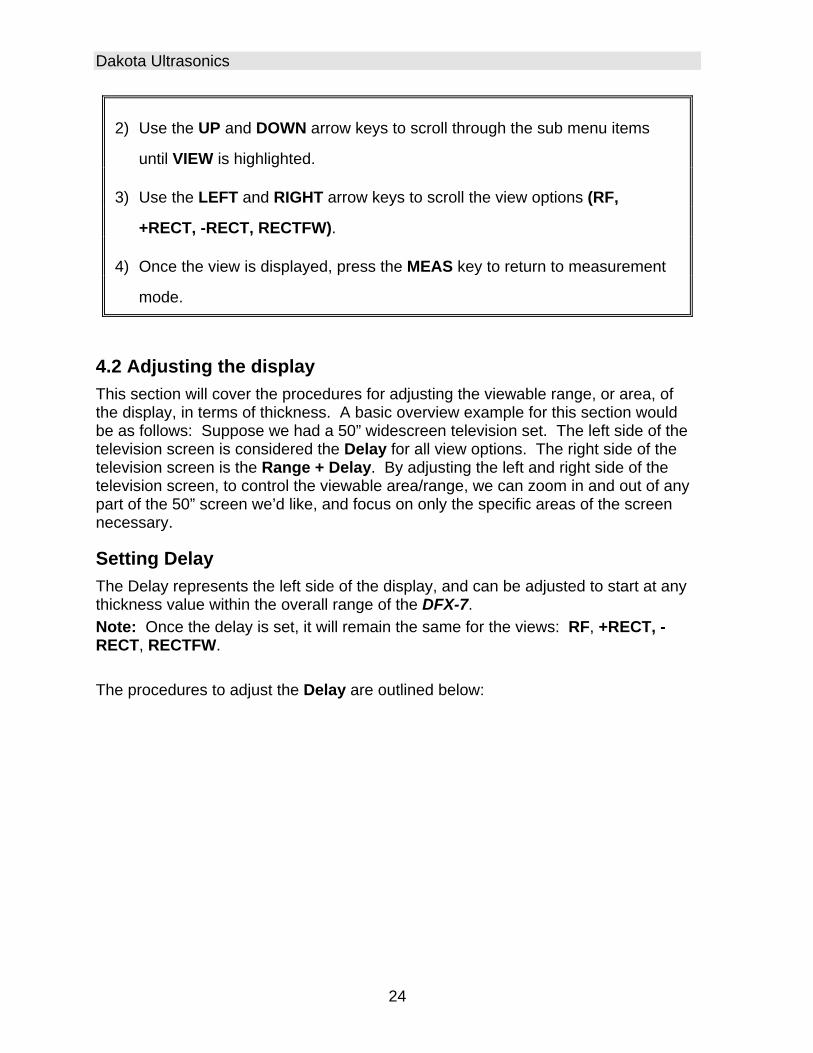
2) Use the UP and DOWN arrow keys to scroll through the sub menu items
until VIEW is highlighted.
3) Use the LEFT and RIGHT arrow keys to scroll the view options (RF,
+RECT, -RECT, RECTFW).
4) Once the view is displayed, press the MEAS key to return to measurement
mode.
4.2 Adjusting the display This section will cover the procedures for adjusting the viewable range, or area, of the display, in terms of thickness. A basic overview example for this section would be as follows: Suppose we had a 50” widescreen television set. The left side of the television screen is considered the Delay for all view options. The right side of the television screen is the Range + Delay. By adjusting the left and right side of the television screen, to control the viewable area/range, we can zoom in and out of any part of the 50” screen we’d like, and focus on only the specific areas of the screen necessary.
Setting Delay The Delay represents the left side of the display, and can be adjusted to start at any thickness value within the overall range of the DFX-7. Note: Once the delay is set, it will remain the same for the views: RF, +RECT, -RECT, RECTFW. The procedures to adjust the Delay are outlined below:

DFX-7 Ultrasonic Flaw Detector
25
Setting Delay
1) Press the MEAS key once to activate measure menu items. Press the
MEAS key multiple times to move right and the ESC key multiple times to
move left, until the DELAY cell is highlighted.
2) Press the UP, DOWN, LEFT, and RIGHT arrow keys to scroll the highlighted
value.
3) Alternatively, press the ENTER key to display the Digits Edit Box.
4) Press the UP and DOWN arrow keys to scroll the highlighted value.
5) Press the LEFT and RIGHT arrow keys to scroll the digit locations.
6) Repeat steps 4 & 5 until the DELAY value is correctly displayed.
7) Press the OK key to return to the measurement screen, or ESC to cancel
entering the DELAY.
8) Finally, press the MEAS key to return to the measurement screen.
Setting Range
Dakota Ultrasonics
26
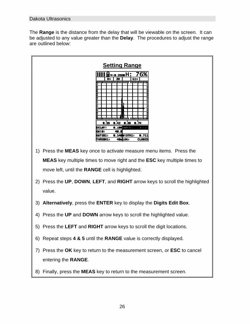
The Range is the distance from the delay that will be viewable on the screen. It can be adjusted to any value greater than the Delay. The procedures to adjust the range are outlined below:
Setting Range
1) Press the MEAS key once to activate measure menu items. Press the
MEAS key multiple times to move right and the ESC key multiple times to
move left, until the RANGE cell is highlighted.
2) Press the UP, DOWN, LEFT, and RIGHT arrow keys to scroll the highlighted
value.
3) Alternatively, press the ENTER key to display the Digits Edit Box.
4) Press the UP and DOWN arrow keys to scroll the highlighted value.
5) Press the LEFT and RIGHT arrow keys to scroll the digit locations.
6) Repeat steps 4 & 5 until the RANGE value is correctly displayed.
7) Press the OK key to return to the measurement screen, or ESC to cancel
entering the RANGE.
8) Finally, press the MEAS key to return to the measurement screen.
DFX-7 Ultrasonic Flaw Detector
27
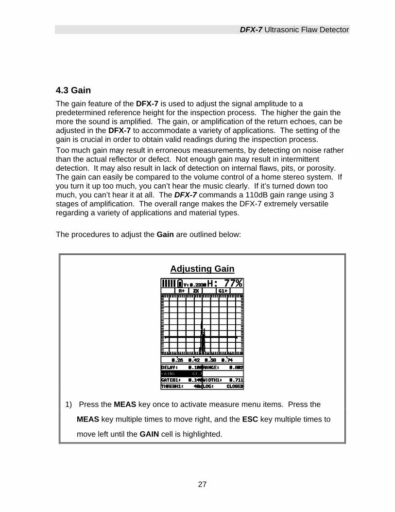
4.3 Gain The gain feature of the DFX-7 is used to adjust the signal amplitude to a predetermined reference height for the inspection process. The higher the gain the more the sound is amplified. The gain, or amplification of the return echoes, can be adjusted in the DFX-7 to accommodate a variety of applications. The setting of the gain is crucial in order to obtain valid readings during the inspection process. Too much gain may result in erroneous measurements, by detecting on noise rather than the actual reflector or defect. Not enough gain may result in intermittent detection. It may also result in lack of detection on internal flaws, pits, or porosity. The gain can easily be compared to the volume control of a home stereo system. If you turn it up too much, you can’t hear the music clearly. If it’s turned down too much, you can’t hear it at all. The DFX-7 commands a 110dB gain range using 3 stages of amplification. The overall range makes the DFX-7 extremely versatile regarding a variety of applications and material types. The procedures to adjust the Gain are outlined below:
Adjusting Gain
1) Press the MEAS key once to activate measure menu items. Press the
MEAS key multiple times to move right, and the ESC key multiple times to
move left until the GAIN cell is highlighted.
Dakota Ultrasonics
28
2) Press the UP, DOWN, LEFT, and RIGHT arrow keys to scroll the highlighted
value.
3) Alternatively, press the ENTER key to display the Digits Edit Box.
4) Press the UP and DOWN arrow keys to scroll the highlighted value.
5) Press the LEFT and RIGHT arrow keys to scroll the digit locations.
6) Repeat steps 4 & 5 until the GAIN value is correctly displayed.
7) Press the OK key to return to the measurement screen, or ESC to cancel
entering the GAIN.
DFX-7 Ultrasonic Flaw Detector
29
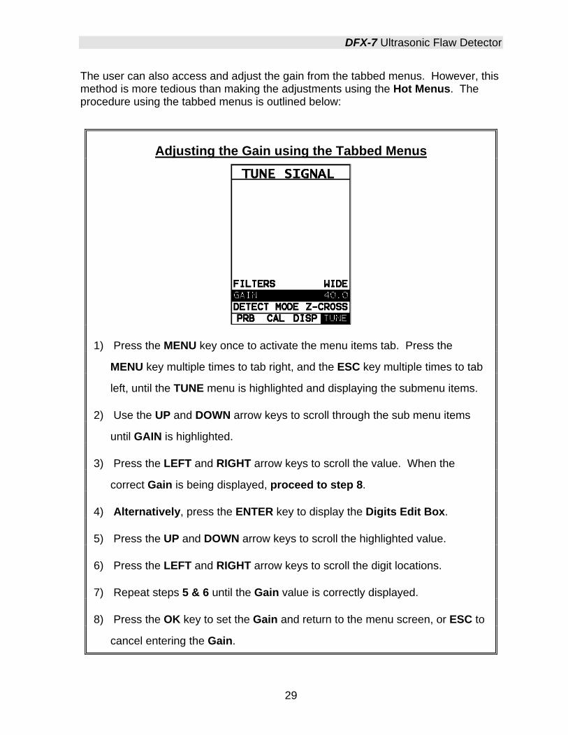
The user can also access and adjust the gain from the tabbed menus. However, this method is more tedious than making the adjustments using the Hot Menus. The procedure using the tabbed menus is outlined below:
Adjusting the Gain using the Tabbed Menus
1) Press the MENU key once to activate the menu items tab. Press the
MENU key multiple times to tab right, and the ESC key multiple times to tab
left, until the TUNE menu is highlighted and displaying the submenu items.
2) Use the UP and DOWN arrow keys to scroll through the sub menu items
until GAIN is highlighted.
3) Press the LEFT and RIGHT arrow keys to scroll the value. When the
correct Gain is being displayed, proceed to step 8.
4) Alternatively, press the ENTER key to display the Digits Edit Box.
5) Press the UP and DOWN arrow keys to scroll the highlighted value.
6) Press the LEFT and RIGHT arrow keys to scroll the digit locations.
7) Repeat steps 5 & 6 until the Gain value is correctly displayed.
8) Press the OK key to set the Gain and return to the menu screen, or ESC to
cancel entering the Gain.
Dakota Ultrasonics
30
9) Finally, press the MEAS key to return to the measurement screen.
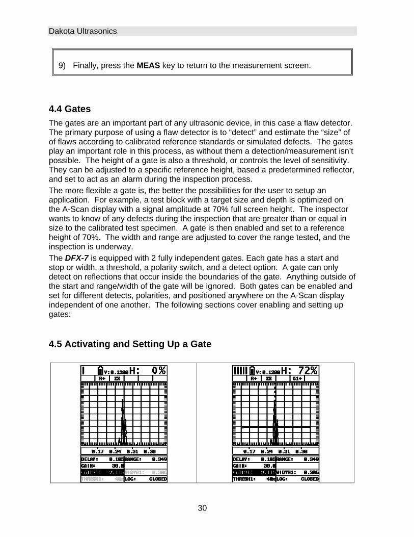
4.4 Gates The gates are an important part of any ultrasonic device, in this case a flaw detector. The primary purpose of using a flaw detector is to “detect” and estimate the “size” of of flaws according to calibrated reference standards or simulated defects. The gates play an important role in this process, as without them a detection/measurement isn’t possible. The height of a gate is also a threshold, or controls the level of sensitivity. They can be adjusted to a specific reference height, based a predetermined reflector, and set to act as an alarm during the inspection process. The more flexible a gate is, the better the possibilities for the user to setup an application. For example, a test block with a target size and depth is optimized on the A-Scan display with a signal amplitude at 70% full screen height. The inspector wants to know of any defects during the inspection that are greater than or equal in size to the calibrated test specimen. A gate is then enabled and set to a reference height of 70%. The width and range are adjusted to cover the range tested, and the inspection is underway. The DFX-7 is equipped with 2 fully independent gates. Each gate has a start and stop or width, a threshold, a polarity switch, and a detect option. A gate can only detect on reflections that occur inside the boundaries of the gate. Anything outside of the start and range/width of the gate will be ignored. Both gates can be enabled and set for different detects, polarities, and positioned anywhere on the A-Scan display independent of one another. The following sections cover enabling and setting up gates:
4.5 Activating and Setting Up a Gate
DFX-7 Ultrasonic Flaw Detector
31
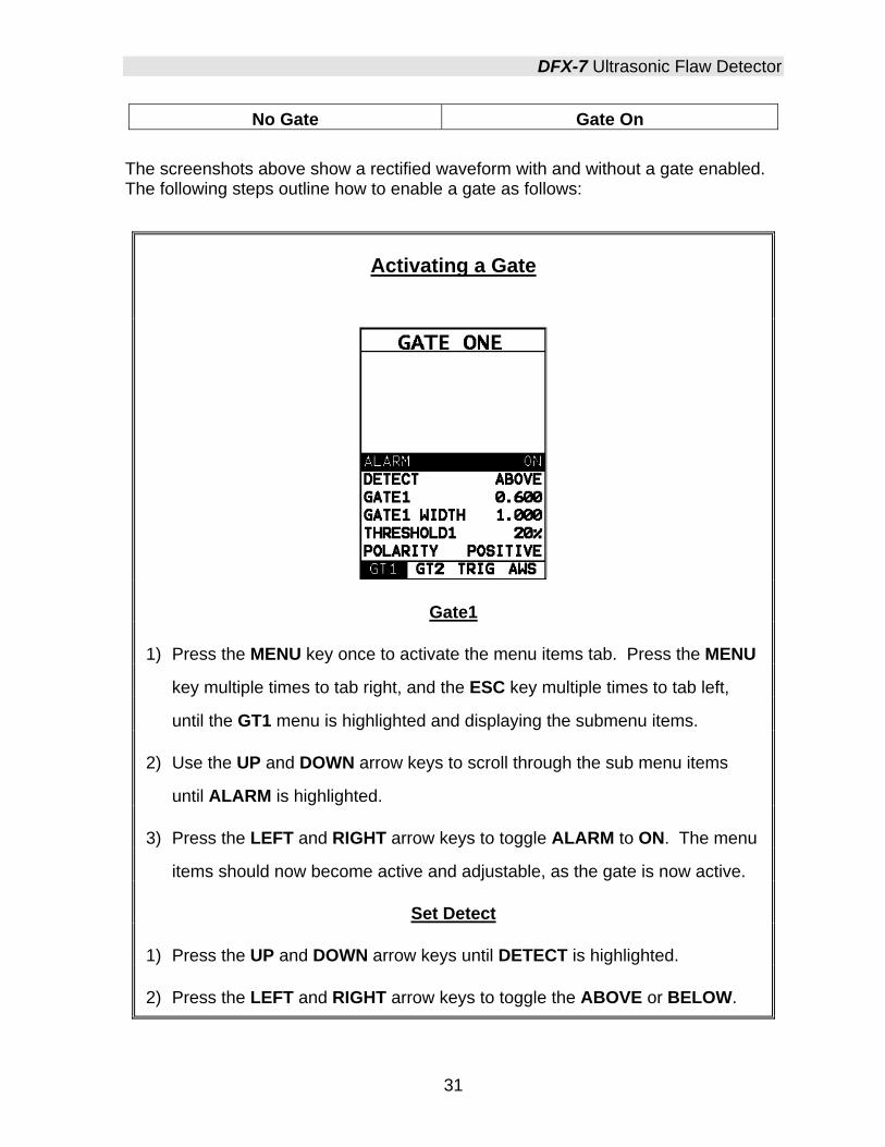
No Gate Gate On The screenshots above show a rectified waveform with and without a gate enabled. The following steps outline how to enable a gate as follows:
Activating a Gate
Gate1
1) Press the MENU key once to activate the menu items tab. Press the MENU
key multiple times to tab right, and the ESC key multiple times to tab left,
until the GT1 menu is highlighted and displaying the submenu items.
2) Use the UP and DOWN arrow keys to scroll through the sub menu items
until ALARM is highlighted.
3) Press the LEFT and RIGHT arrow keys to toggle ALARM to ON. The menu
items should now become active and adjustable, as the gate is now active.
Set Detect
1) Press the UP and DOWN arrow keys until DETECT is highlighted.
2) Press the LEFT and RIGHT arrow keys to toggle the ABOVE or BELOW.
Dakota Ultrasonics
32
Note: Above will trigger the alarm when a signal meets or exceeds the height
of the gate, and below will detect on anything that meets or is below the height
of the gate.
Set Gate1 Start
1) Press the UP and DOWN arrow keys until GATE1 is highlighted, followed by
pressing the LEFT and RIGHT arrow keys to scroll the value. When the
correct start position is displayed, proceed to the next setting.
2) Alternatively, press the ENTER key to display the Digits Edit Box.
3) Press the UP and DOWN arrow keys to scroll the highlighted value.
4) Press the LEFT and RIGHT arrow keys to scroll the digit locations.
5) Repeat steps 3 & 4 until the start position is correctly displayed.
6) Press the OK key to set the GATE1 start position and return to the menu
screen, or ESC to cancel entering the GATE1 start position.
Note: This where the gate first turn on relative to the horizontal axis or depth.
Sets the left boundary of the gate, or where it turns on.
Set Gate1 Width
1) Press the UP and DOWN arrow keys until GATE1 WIDTH is highlighted,
followed by pressing the LEFT and RIGHT arrow keys to scroll the value.
When the correct width is displayed, proceed to the next setting.
2) Alternatively, press the ENTER key to display the Digits Edit Box.
3) Press the UP and DOWN arrow keys to scroll the highlighted value.
4) Press the LEFT and RIGHT arrow keys to scroll the digit locations.
5) Repeat steps 3 & 4 until the width is correctly displayed.
DFX-7 Ultrasonic Flaw Detector
33
6) Press the OK key to set the GATE1 WIDTH and return to the menu screen,
or ESC to cancel entering the GATE1 WIDTH.
Note: This sets the overall width of the gate in terms of the horizontal axis or
depth. Sets the right boundary of the gate, or where it turns off.
Set Threshold1 Level
1) Press the UP and DOWN arrow keys until THRESHOLD1 is highlighted,
followed by pressing the LEFT and RIGHT arrow keys to scroll the value.
When the correct threshold level is displayed, proceed to the next setting.
2) Alternatively, press the ENTER key to display the Digits Edit Box.
3) Press the UP and DOWN arrow keys to scroll the highlighted value.
4) Press the LEFT and RIGHT arrow keys to scroll the digit locations.
5) Repeat steps 3 & 4 until the threshold level is correctly displayed.
6) Press the OK key to set the THRESHOLD1 level and return to the menu
screen, or ESC to cancel entering the THRESHOLD1 level.
Note: This sets the overall sensitivity level of the gate which is the threshold.
Select Gate Polarity
1) Use the UP and DOWN arrow keys to scroll through the sub menu items
until POLARITY1 is highlighted.
2) Press the LEFT and RIGHT arrow keys to toggle the POLARITY feature
positive or negative.
3) Press the MEAS key to return to the measurement screen.
Note: The GATE1 and WIDTH1 values can now be adjusted or tuned directly
from the Hot Menus on the main measurement screen.
Dakota Ultrasonics
34
Note: Sets where the detection will occur, on the negative or positive going
echoes.
35
CHAPTER FIVE CALIBRATION
In this section we’ll focus on calibrating the DFX-7. There are a number of ways to go about performing a calibration, but we’ll be focusing on the simplest and most accurate method, which is performing a two point calibration. This method is very convenient, as it will automatically calculate the material velocity and zero using a minimum and maximum calibration standard of know thickness and material type. The DFX-7 can certainly be manually calibrated by adjusting the velocity and zero features, but this is a tedious and redundant process overall. The two point calibration method can be used for both straight and angle beam transducers. A number of certified calibration standards are available to address inspection code requirements, specifications, and applications. It should be noted again that the DFX-7 has virtually 2 gauges built into a single gauge; a flaw detector, and a thickness gauge. Therefore, while the flaw detector option can be calibrated for straight beam contact and angle beam style transducers, the thickness gauge option contains a number of tools for using single and dual element style transducers with linearity tables and v-path correction curves. In addition, it should also be noted that the thickness gauge option has a fully functional scope with the same precision linearity as the flaw detector option. Therefore, the user should consider the current application to determine which gauge option will produce the best results. The following sections outline how to setup and calibrate your DFX-7 for field use, given a specific range and material type.
5.1 Setting Up For Calibration This section covers performing a two point automatic calibration using a single element straight beam contact transducer with a range from 1 to 4 inches. In order to accomplish this, a set of calibration standards covering range is required. The steps are outlined as follows:
DFX-7 Setup
Dakota Ultrasonics
36
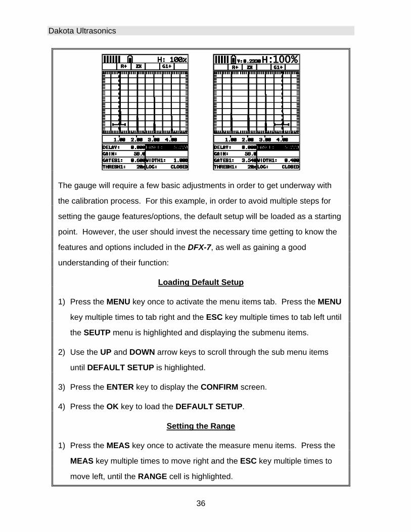
The gauge will require a few basic adjustments in order to get underway with
the calibration process. For this example, in order to avoid multiple steps for
setting the gauge features/options, the default setup will be loaded as a starting
point. However, the user should invest the necessary time getting to know the
features and options included in the DFX-7, as well as gaining a good
understanding of their function:
Loading Default Setup
1) Press the MENU key once to activate the menu items tab. Press the MENU
key multiple times to tab right and the ESC key multiple times to tab left until
the SEUTP menu is highlighted and displaying the submenu items.
2) Use the UP and DOWN arrow keys to scroll through the sub menu items
until DEFAULT SETUP is highlighted.
3) Press the ENTER key to display the CONFIRM screen.
4) Press the OK key to load the DEFAULT SETUP.
Setting the Range
1) Press the MEAS key once to activate the measure menu items. Press the
MEAS key multiple times to move right and the ESC key multiple times to
move left, until the RANGE cell is highlighted.
DFX-7 Ultrasonic Flaw Detector
37
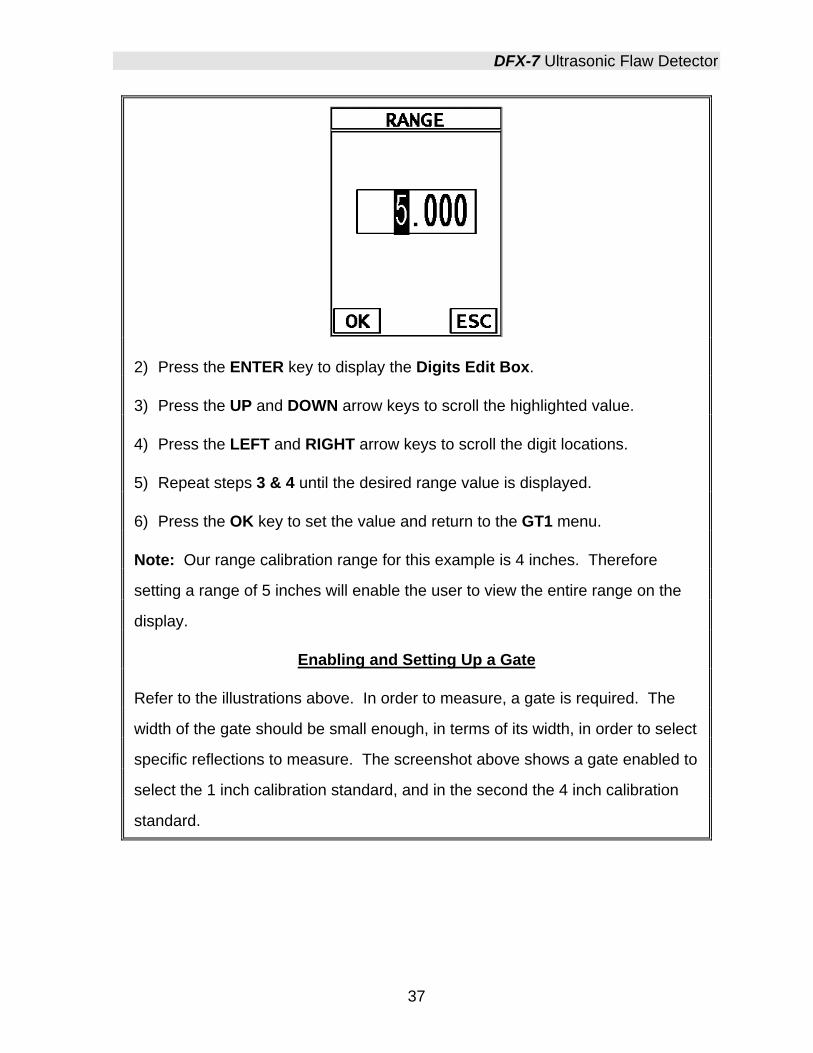
2) Press the ENTER key to display the Digits Edit Box.
3) Press the UP and DOWN arrow keys to scroll the highlighted value.
4) Press the LEFT and RIGHT arrow keys to scroll the digit locations.
5) Repeat steps 3 & 4 until the desired range value is displayed.
6) Press the OK key to set the value and return to the GT1 menu.
Note: Our range calibration range for this example is 4 inches. Therefore
setting a range of 5 inches will enable the user to view the entire range on the
display.
Enabling and Setting Up a Gate
Refer to the illustrations above. In order to measure, a gate is required. The
width of the gate should be small enough, in terms of its width, in order to select
specific reflections to measure. The screenshot above shows a gate enabled to
select the 1 inch calibration standard, and in the second the 4 inch calibration
standard.
Dakota Ultrasonics
38
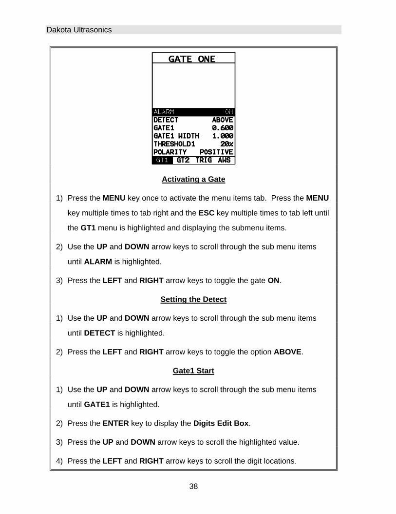
Activating a Gate
1) Press the MENU key once to activate the menu items tab. Press the MENU
key multiple times to tab right and the ESC key multiple times to tab left until
the GT1 menu is highlighted and displaying the submenu items.
2) Use the UP and DOWN arrow keys to scroll through the sub menu items
until ALARM is highlighted.
3) Press the LEFT and RIGHT arrow keys to toggle the gate ON.
Setting the Detect
1) Use the UP and DOWN arrow keys to scroll through the sub menu items
until DETECT is highlighted.
2) Press the LEFT and RIGHT arrow keys to toggle the option ABOVE.
Gate1 Start
1) Use the UP and DOWN arrow keys to scroll through the sub menu items
until GATE1 is highlighted.
2) Press the ENTER key to display the Digits Edit Box.
3) Press the UP and DOWN arrow keys to scroll the highlighted value.
4) Press the LEFT and RIGHT arrow keys to scroll the digit locations.
DFX-7 Ultrasonic Flaw Detector
39
5) Repeat steps 3 & 4 until the desired GATE1 value is displayed.
Note: In our example, a value less than 1 inch should be selected.
6) Press the OK key to set the value and return to the GT1 menu.
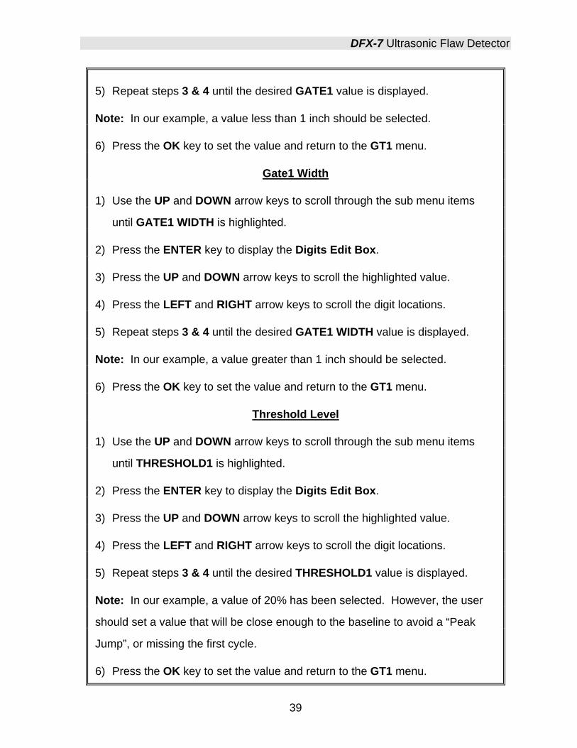
Gate1 Width
1) Use the UP and DOWN arrow keys to scroll through the sub menu items
until GATE1 WIDTH is highlighted.
2) Press the ENTER key to display the Digits Edit Box.
3) Press the UP and DOWN arrow keys to scroll the highlighted value.
4) Press the LEFT and RIGHT arrow keys to scroll the digit locations.
5) Repeat steps 3 & 4 until the desired GATE1 WIDTH value is displayed.
Note: In our example, a value greater than 1 inch should be selected.
6) Press the OK key to set the value and return to the GT1 menu.
Threshold Level
1) Use the UP and DOWN arrow keys to scroll through the sub menu items
until THRESHOLD1 is highlighted.
2) Press the ENTER key to display the Digits Edit Box.
3) Press the UP and DOWN arrow keys to scroll the highlighted value.
4) Press the LEFT and RIGHT arrow keys to scroll the digit locations.
5) Repeat steps 3 & 4 until the desired THRESHOLD1 value is displayed.
Note: In our example, a value of 20% has been selected. However, the user
should set a value that will be close enough to the baseline to avoid a “Peak
Jump”, or missing the first cycle.
6) Press the OK key to set the value and return to the GT1 menu.
Dakota Ultrasonics
40
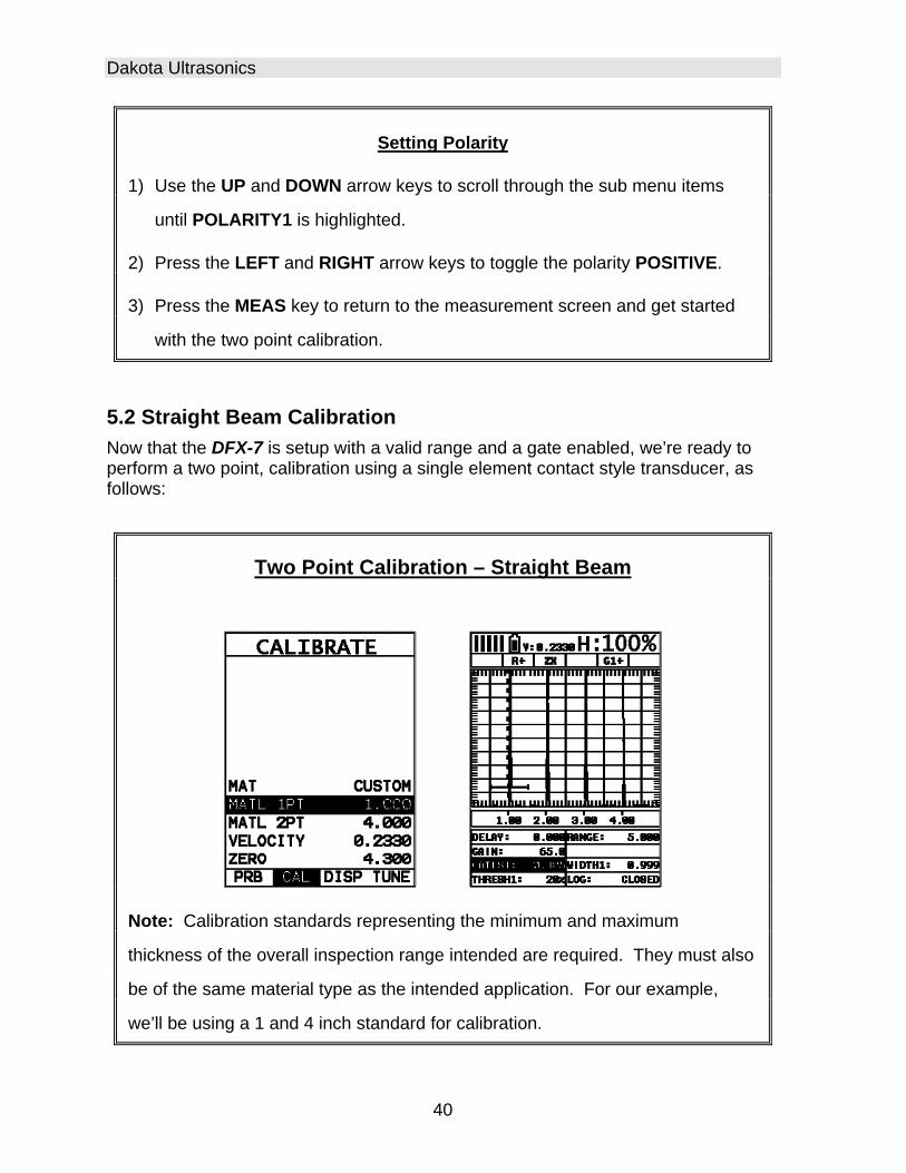
Setting Polarity
1) Use the UP and DOWN arrow keys to scroll through the sub menu items
until POLARITY1 is highlighted.
2) Press the LEFT and RIGHT arrow keys to toggle the polarity POSITIVE.
3) Press the MEAS key to return to the measurement screen and get started
with the two point calibration.
5.2 Straight Beam Calibration Now that the DFX-7 is setup with a valid range and a gate enabled, we’re ready to perform a two point, calibration using a single element contact style transducer, as follows:
Two Point Calibration – Straight Beam
Note: Calibration standards representing the minimum and maximum
thickness of the overall inspection range intended are required. They must also
be of the same material type as the intended application. For our example,
we’ll be using a 1 and 4 inch standard for calibration.
DFX-7 Ultrasonic Flaw Detector
41
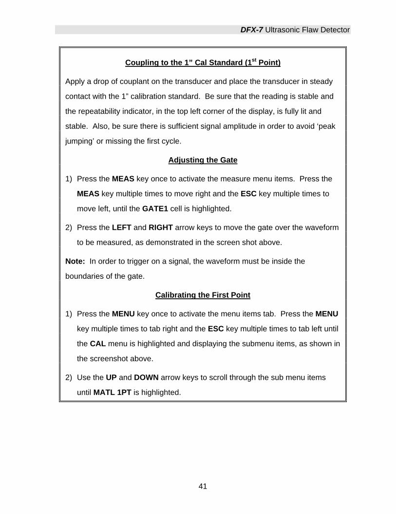
Coupling to the 1” Cal Standard (1st Point)
Apply a drop of couplant on the transducer and place the transducer in steady
contact with the 1” calibration standard. Be sure that the reading is stable and
the repeatability indicator, in the top left corner of the display, is fully lit and
stable. Also, be sure there is sufficient signal amplitude in order to avoid ‘peak
jumping’ or missing the first cycle.
Adjusting the Gate
1) Press the MEAS key once to activate the measure menu items. Press the
MEAS key multiple times to move right and the ESC key multiple times to
move left, until the GATE1 cell is highlighted.
2) Press the LEFT and RIGHT arrow keys to move the gate over the waveform
to be measured, as demonstrated in the screen shot above.
Note: In order to trigger on a signal, the waveform must be inside the
boundaries of the gate.
Calibrating the First Point
1) Press the MENU key once to activate the menu items tab. Press the MENU
key multiple times to tab right and the ESC key multiple times to tab left until
the CAL menu is highlighted and displaying the submenu items, as shown in
the screenshot above.
2) Use the UP and DOWN arrow keys to scroll through the sub menu items
until MATL 1PT is highlighted.
Dakota Ultrasonics
42
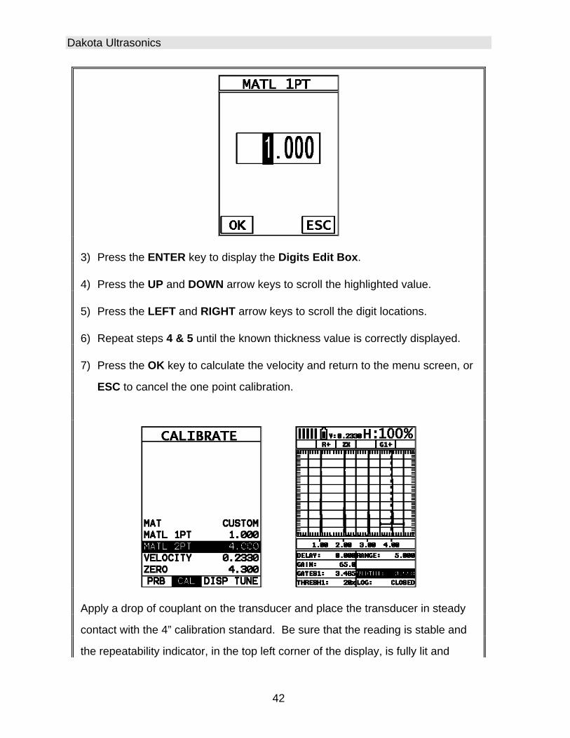
3) Press the ENTER key to display the Digits Edit Box.
4) Press the UP and DOWN arrow keys to scroll the highlighted value.
5) Press the LEFT and RIGHT arrow keys to scroll the digit locations.
6) Repeat steps 4 & 5 until the known thickness value is correctly displayed.
7) Press the OK key to calculate the velocity and return to the menu screen, or
ESC to cancel the one point calibration.
Apply a drop of couplant on the transducer and place the transducer in steady
contact with the 4” calibration standard. Be sure that the reading is stable and
the repeatability indicator, in the top left corner of the display, is fully lit and
DFX-7 Ultrasonic Flaw Detector
43
stable. Also, be sure there is sufficient signal amplitude in order to avoid ‘peak
jumping’ or missing the first cycle.
Adjusting the Gate
1) Press the MEAS key once to activate the measure menu items. Press the
MEAS key multiple times to move right and the ESC key multiple times to
move left, until the GATE1 cell is highlighted.
2) Press the LEFT and RIGHT arrow keys to move the gate over the waveform
to be measured, as demonstrated in the screen shot above.
Note: In order to trigger on a signal, the waveform must be inside the
boundaries of the gate.
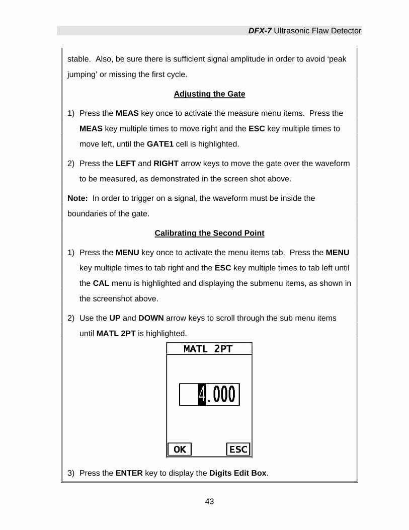
Calibrating the Second Point
1) Press the MENU key once to activate the menu items tab. Press the MENU
key multiple times to tab right and the ESC key multiple times to tab left until
the CAL menu is highlighted and displaying the submenu items, as shown in
the screenshot above.
2) Use the UP and DOWN arrow keys to scroll through the sub menu items
until MATL 2PT is highlighted.
3) Press the ENTER key to display the Digits Edit Box.
Dakota Ultrasonics
44
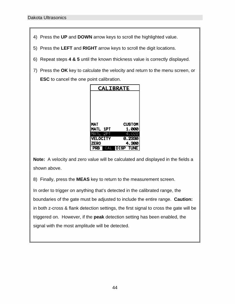
4) Press the UP and DOWN arrow keys to scroll the highlighted value.
5) Press the LEFT and RIGHT arrow keys to scroll the digit locations.
6) Repeat steps 4 & 5 until the known thickness value is correctly displayed.
7) Press the OK key to calculate the velocity and return to the menu screen, or
ESC to cancel the one point calibration.
Note: A velocity and zero value will be calculated and displayed in the fields a
shown above.
8) Finally, press the MEAS key to return to the measurement screen.
In order to trigger on anything that’s detected in the calibrated range, the
boundaries of the gate must be adjusted to include the entire range. Caution:
in both z-cross & flank detection settings, the first signal to cross the gate will be
triggered on. However, if the peak detection setting has been enabled, the
signal with the most amplitude will be detected.
DFX-7 Ultrasonic Flaw Detector
45
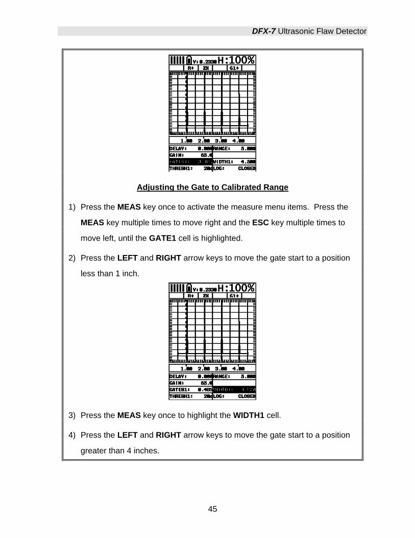
Adjusting the Gate to Calibrated Range
1) Press the MEAS key once to activate the measure menu items. Press the
MEAS key multiple times to move right and the ESC key multiple times to
move left, until the GATE1 cell is highlighted.
2) Press the LEFT and RIGHT arrow keys to move the gate start to a position
less than 1 inch.
3) Press the MEAS key once to highlight the WIDTH1 cell.
4) Press the LEFT and RIGHT arrow keys to move the gate start to a position
greater than 4 inches.
Dakota Ultrasonics
46
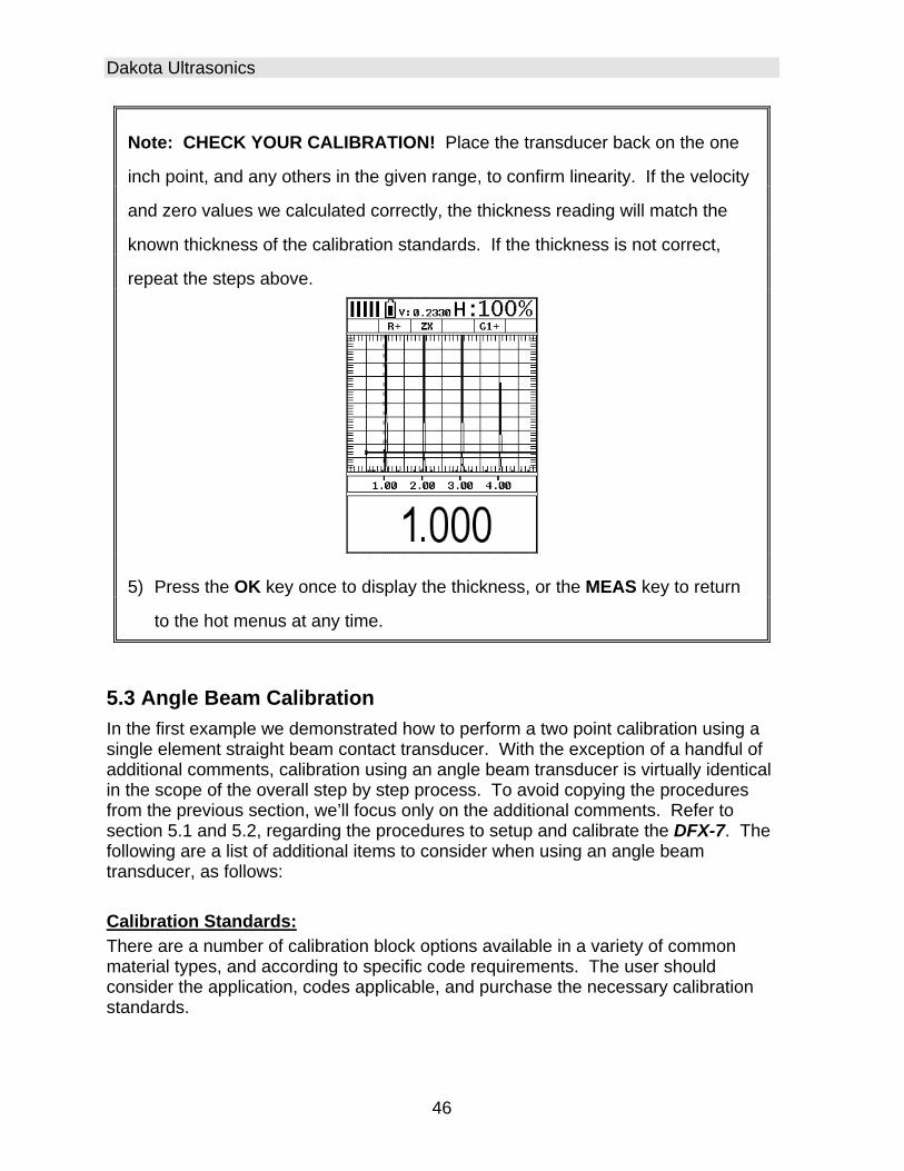
Note: CHECK YOUR CALIBRATION! Place the transducer back on the one
inch point, and any others in the given range, to confirm linearity. If the velocity
and zero values we calculated correctly, the thickness reading will match the
known thickness of the calibration standards. If the thickness is not correct,
repeat the steps above.
5) Press the OK key once to display the thickness, or the MEAS key to return
to the hot menus at any time.
5.3 Angle Beam Calibration In the first example we demonstrated how to perform a two point calibration using a single element straight beam contact transducer. With the exception of a handful of additional comments, calibration using an angle beam transducer is virtually identical in the scope of the overall step by step process. To avoid copying the procedures from the previous section, we’ll focus only on the additional comments. Refer to section 5.1 and 5.2, regarding the procedures to setup and calibrate the DFX-7. The following are a list of additional items to consider when using an angle beam transducer, as follows: Calibration Standards: There are a number of calibration block options available in a variety of common material types, and according to specific code requirements. The user should consider the application, codes applicable, and purchase the necessary calibration standards.
DFX-7 Ultrasonic Flaw Detector
47
Shear versus Longitudinal Velocity: Unlike the previous straight beam calibration, which uses a longitudinal wave, an angle beam transducer uses a shear wave. The following is a brief review of the waves:
• Longitudinal – o Particle motion is parallel to the direction of wave travel. o Travels in solids, liquids, and gasses. o Fastest mode of vibration.
• Shear – o Particle motion is perpendicular to the direction of wave travel. o Travels only in solids. o Is approximately ½ the velocity of longitudinal waves. o Has a shorter wavelength than a longitudinal at the same frequency.
Therefore, a two point calibration using an angle beam transducer will result in a velocity approximately ½ the speed of the velocity calculated from the straight beam calibration in the previous section. Gain and Amplitude Ratio: During an angle beam calibration the overall amplitude height of the waveform is critical for “peaking up”. Therefore the maximum amplitude of the waveform must be visible on the display in order to correctly position the transducer on the calibration standard. The user should select a screen height and gain level that will enable the entire waveform to be visible on the display. Peaking Up the Signal Amplitude: During an angle beam calibration, it’s important to peak up the overall amplitude of the waveform to its maximum potential. The primary purpose is to be sure the transducer is positioned properly on the calibration standard, that’s producing return echoes at different distances. For example: If the operator is using a DSC block to calibrate the velocity and zero, a DSC block will produce echoes at 3 & 7 inches. The operator then positions the transducer on an index point, moves the transducer in both directions forward and backward, rotates it side to side, and watches the signal amplitude to find the maximum potential. At the maximum potential, the transducer is correctly positioned to measure both multiple echoes at the correct distances, and ready to proceed with the calibration. Selecting the Material Type: The user can also select a material type directly from a table built into the DFX-7 with shear wave values. This would only get the user close, in terms of velocity, to the calibration standards material type. In order to display the material chart with shear
Dakota Ultrasonics
48
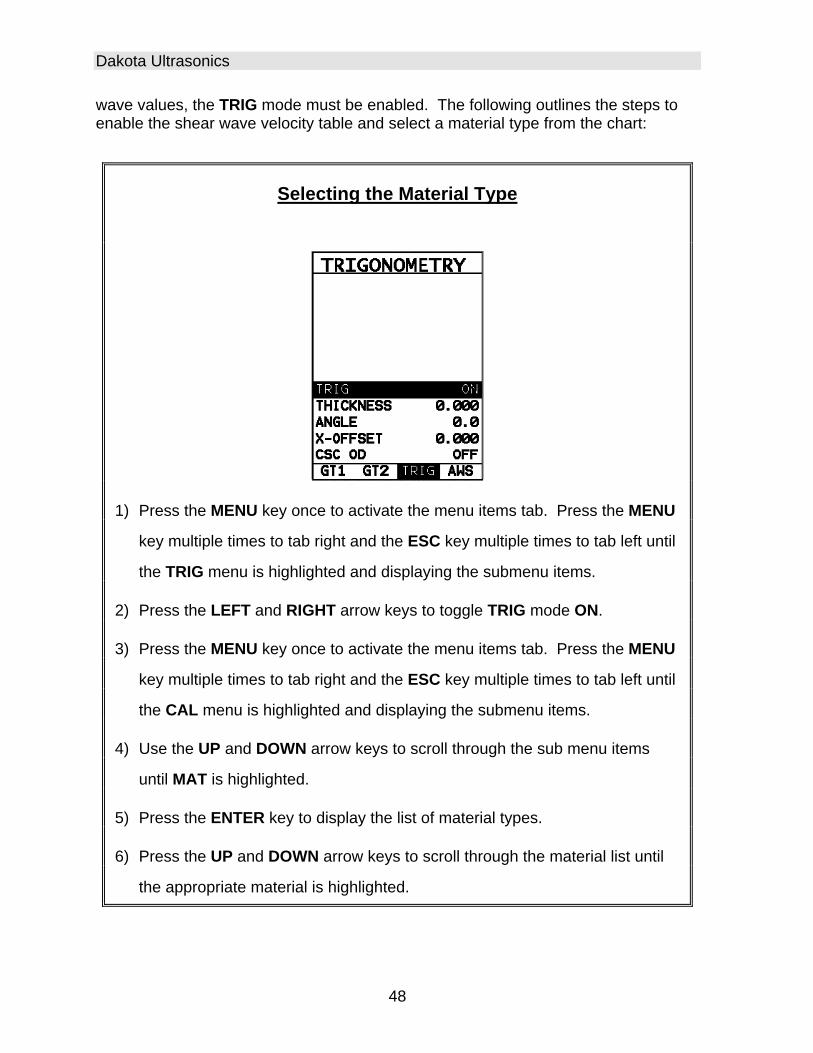
wave values, the TRIG mode must be enabled. The following outlines the steps to enable the shear wave velocity table and select a material type from the chart:
Selecting the Material Type
1) Press the MENU key once to activate the menu items tab. Press the MENU
key multiple times to tab right and the ESC key multiple times to tab left until
the TRIG menu is highlighted and displaying the submenu items.
2) Press the LEFT and RIGHT arrow keys to toggle TRIG mode ON.
3) Press the MENU key once to activate the menu items tab. Press the MENU
key multiple times to tab right and the ESC key multiple times to tab left until
the CAL menu is highlighted and displaying the submenu items.
4) Use the UP and DOWN arrow keys to scroll through the sub menu items
until MAT is highlighted.
5) Press the ENTER key to display the list of material types.
6) Press the UP and DOWN arrow keys to scroll through the material list until
the appropriate material is highlighted.
DFX-7 Ultrasonic Flaw Detector
49
7) Press the ENTER key to select the material type and initiate the overwrite
confirmation screen.
8) Press the OK key to confirm the material selection, or ESC key to cancel
changing the material type.
50
CHAPTER SIX TRIGONOMETRY MODE
6.1 Introduction to TRIG Trig mode is most commonly used for inspecting welded joints using an angle beam transducer. Based on the location, orientation, and geometry of the weld, a straight beam transducer is typically not suitable for inspection. As a result, a transducer emitting sound at a given angle will allow the operator to position the transducer away from the actual weld, and “skip” into the weld at a given angle. Therefore, in order to determine the location of a defect, given a specific angle, the trigonometry mode is used. This section will cover the steps to setup and utilize trigonometry mode.
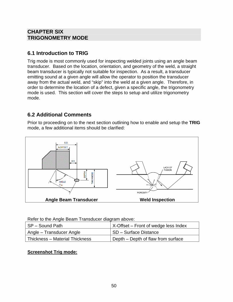
6.2 Additional Comments Prior to proceeding on to the next section outlining how to enable and setup the TRIG mode, a few additional items should be clarified:
Angle Beam Transducer Weld Inspection Refer to the Angle Beam Transducer diagram above: SP – Sound Path X-Offset – Front of wedge less Index Angle – Transducer Angle SD – Surface Distance Thickness – Material Thickness Depth – Depth of flaw from surface Screenshot Trig mode:

DFX-7 Ultrasonic Flaw Detector
51
When TRIG mode is enabled, the calculated measurements will be displayed below the waveform display area at (A), and the signal amplitude as a percentage of full screen height at (B). Curved Surface Correction:
The DFX-7 will also compensate for convex curved surfaces of longitudinally welded pipes. A curved surface will produce a greater sound path than a flat surface will, using a transducer with a given angle. The user should consider the angle used on curved surfaces, with respect to the material thickness, in order to be sure a reflection will occur from the opposite surface of the test material. In order to utilize the curved surface compensation, the outside diameter must be entered into the DFX-7.
6.3 Setup Trigonometry Mode This section provides a step by step procedure to enable and setup the TRIG mode. Note: A two point calibration should be done prior to proceeding. Refer to Chapter Five for the calibration procedures.
Dakota Ultrasonics
52
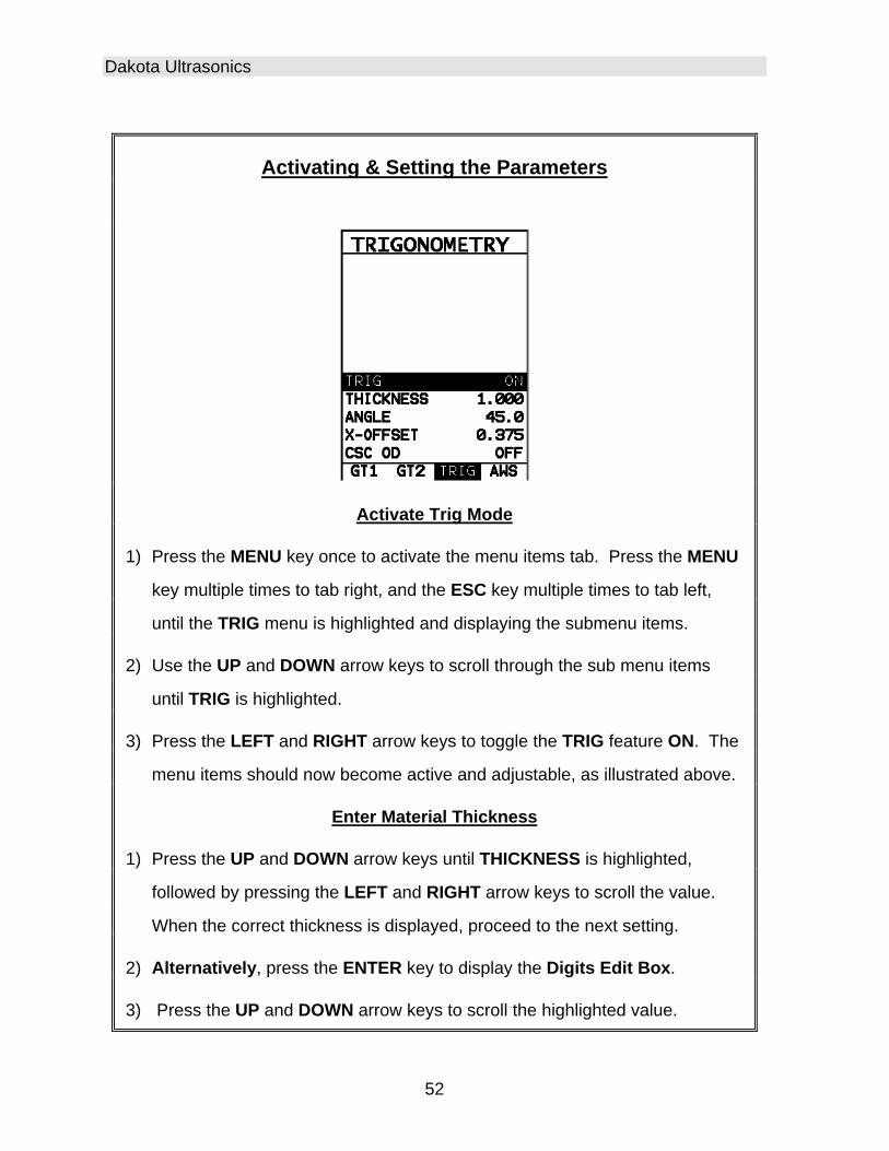
Activating & Setting the Parameters
Activate Trig Mode
1) Press the MENU key once to activate the menu items tab. Press the MENU
key multiple times to tab right, and the ESC key multiple times to tab left,
until the TRIG menu is highlighted and displaying the submenu items.
2) Use the UP and DOWN arrow keys to scroll through the sub menu items
until TRIG is highlighted.
3) Press the LEFT and RIGHT arrow keys to toggle the TRIG feature ON. The
menu items should now become active and adjustable, as illustrated above.
Enter Material Thickness
1) Press the UP and DOWN arrow keys until THICKNESS is highlighted,
followed by pressing the LEFT and RIGHT arrow keys to scroll the value.
When the correct thickness is displayed, proceed to the next setting.
2) Alternatively, press the ENTER key to display the Digits Edit Box.
3) Press the UP and DOWN arrow keys to scroll the highlighted value.
DFX-7 Ultrasonic Flaw Detector
53
4) Press the LEFT and RIGHT arrow keys to scroll the digit locations.
5) Repeat steps 3 & 4 until the thickness is correctly displayed.
6) Press the OK key to set the THICKNESS and return to the menu screen, or
ESC to cancel entering the THICKNESS.
Note: Thickness is used to calculate the depth.
Transducer Angle
1) Press the UP and DOWN arrow keys until ANGLE is highlighted, followed
by pressing the LEFT and RIGHT arrow keys to scroll the value. When the
correct angle is displayed, proceed to the next setting.
2) Alternatively, press the ENTER key to display the Digits Edit Box.
3) Press the UP and DOWN arrow keys to scroll the highlighted value.
4) Press the LEFT and RIGHT arrow keys to scroll the digit locations.
5) Repeat steps 3 & 4 until the angle is correctly displayed.
6) Press the OK key to set the ANGLE and return to the menu screen, or ESC
to cancel entering the ANGLE.
X-Offset
1) Press the UP and DOWN arrow keys until X-OFFSET is highlighted,
followed by pressing the LEFT and RIGHT arrow keys to scroll the value.
When the correct X-Offset is displayed, proceed to the next setting.
2) Alternatively, press the ENTER key to display the Digits Edit Box.
3) Press the UP and DOWN arrow keys to scroll the highlighted value.
4) Press the LEFT and RIGHT arrow keys to scroll the digit locations.
5) Repeat steps 3 & 4 until the X-Offset is correctly displayed.
Dakota Ultrasonics
54
6) Press the OK key to set the X-OFFSET and return to the menu screen, or
ESC to cancel entering the X-OFFSET.
Note: The X-Offset is used for purposes of marking, and is physically
measured with a ruler from the index point to the front edge of the transducer.
Curved Surface Outside Diameter
1) Press the UP and DOWN arrow keys until CSC OD is highlighted, followed
by pressing the LEFT and RIGHT arrow keys to scroll the value. When the
correct CSC OD is displayed, proceed to the next setting.
2) Alternatively, press the ENTER key to display the Digits Edit Box.
3) Press the UP and DOWN arrow keys to scroll the highlighted value.
4) Press the LEFT and RIGHT arrow keys to scroll the digit locations.
5) Repeat steps 3 & 4 until the CSC OD is correctly displayed.
6) Press the OK key to set the CSC OD and return to the menu screen, or ESC
to cancel entering the CSC OD.
Note: The CSC OD value is only used for curved surfaces of longitudinally
welded pipes.
55
CHAPTER SEVEN AWS – WELD INSPECTION
7.1 Introduction to AWS AWS provides a toolkit for evaluating defects according to the American Welding Society D1.1 welding code. The code offers inspectors a method to classify discontinuities by calculating and Indication Rating (IR) using ultrasonics. This toolkit can be used in conjunction with TRIG mode, outlined in the previous chapter, to simultaneously display the sound path (SP), surface distance (SD), and depth (D). The following sections provide an outline for using the AWS feature.
7.2 Additional Comments Since the DFX-7 is a gain controlled instrument, the following formula applies:
A – B – C = D Where: A = Discontinuity Indication Rating (DI) B = Reference Indication Level (IL) C = Attenuation Factor (AF); or 2(SP – 1) SP = sound path in inches (2dB loss per inch of material thickness) D = Indication Rating (IR) Note: all values are in dB. Calibration Standards & Calibration: In order to use the AWS feature, the operator must have calibration standards made with the same size reflector at different distances within the testing range. The standards should also be made of the same material type as the material to be inspected. AWS D1.1 Standard: There are specific transducers that are required by the D1.1 standard. The frequency specified by the standard is 2-2.5MHz. The user should refer to the standard for further information.
7.3 Setup AWS This section provides a step by step procedure to enable and setup the AWS feature. Note: A two point calibration should be done prior to proceeding. Refer to Chapter Five for the calibration procedures. The TRIG mode will also be used for weld
Dakota Ultrasonics
56
inspection, and should additionally be setup prior to enabling the AWS feature. Refer to Chapter Six for instructions on setting up TRIG mode.
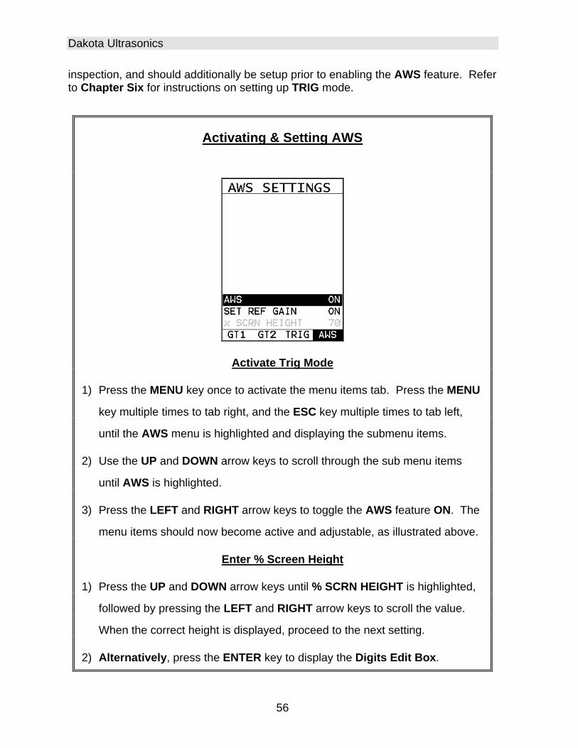
Activating & Setting AWS
Activate Trig Mode
1) Press the MENU key once to activate the menu items tab. Press the MENU
key multiple times to tab right, and the ESC key multiple times to tab left,
until the AWS menu is highlighted and displaying the submenu items.
2) Use the UP and DOWN arrow keys to scroll through the sub menu items
until AWS is highlighted.
3) Press the LEFT and RIGHT arrow keys to toggle the AWS feature ON. The
menu items should now become active and adjustable, as illustrated above.
Enter % Screen Height
1) Press the UP and DOWN arrow keys until % SCRN HEIGHT is highlighted,
followed by pressing the LEFT and RIGHT arrow keys to scroll the value.
When the correct height is displayed, proceed to the next setting.
2) Alternatively, press the ENTER key to display the Digits Edit Box.
DFX-7 Ultrasonic Flaw Detector
57
3) Press the UP and DOWN arrow keys to scroll the highlighted value.
4) Press the LEFT and RIGHT arrow keys to scroll the digit locations.
5) Repeat steps 3 & 4 until the height is correctly displayed.
6) Press the OK key to set the % SCRN HEIGHT and return to the menu
screen, or ESC to cancel entering the % SCRN HEIGHT.
Note: % Screen Height is an arbitrary level, and is not specified by the AWS
D1.1. The user should set a value that will optimize viewing defects that are
larger and smaller than the reference level. Typically this level is set between
50%-80% full screen height.
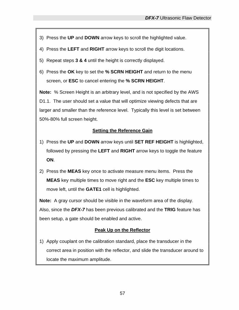
Setting the Reference Gain
1) Press the UP and DOWN arrow keys until SET REF HEIGHT is highlighted,
followed by pressing the LEFT and RIGHT arrow keys to toggle the feature
ON.
2) Press the MEAS key once to activate measure menu items. Press the
MEAS key multiple times to move right and the ESC key multiple times to
move left, until the GATE1 cell is highlighted.
Note: A gray cursor should be visible in the waveform area of the display.
Also, since the DFX-7 has been previous calibrated and the TRIG feature has
been setup, a gate should be enabled and active.
Peak Up on the Reflector
1) Apply couplant on the calibration standard, place the transducer in the
correct area in position with the reflector, and slide the transducer around to
locate the maximum amplitude.
Dakota Ultrasonics
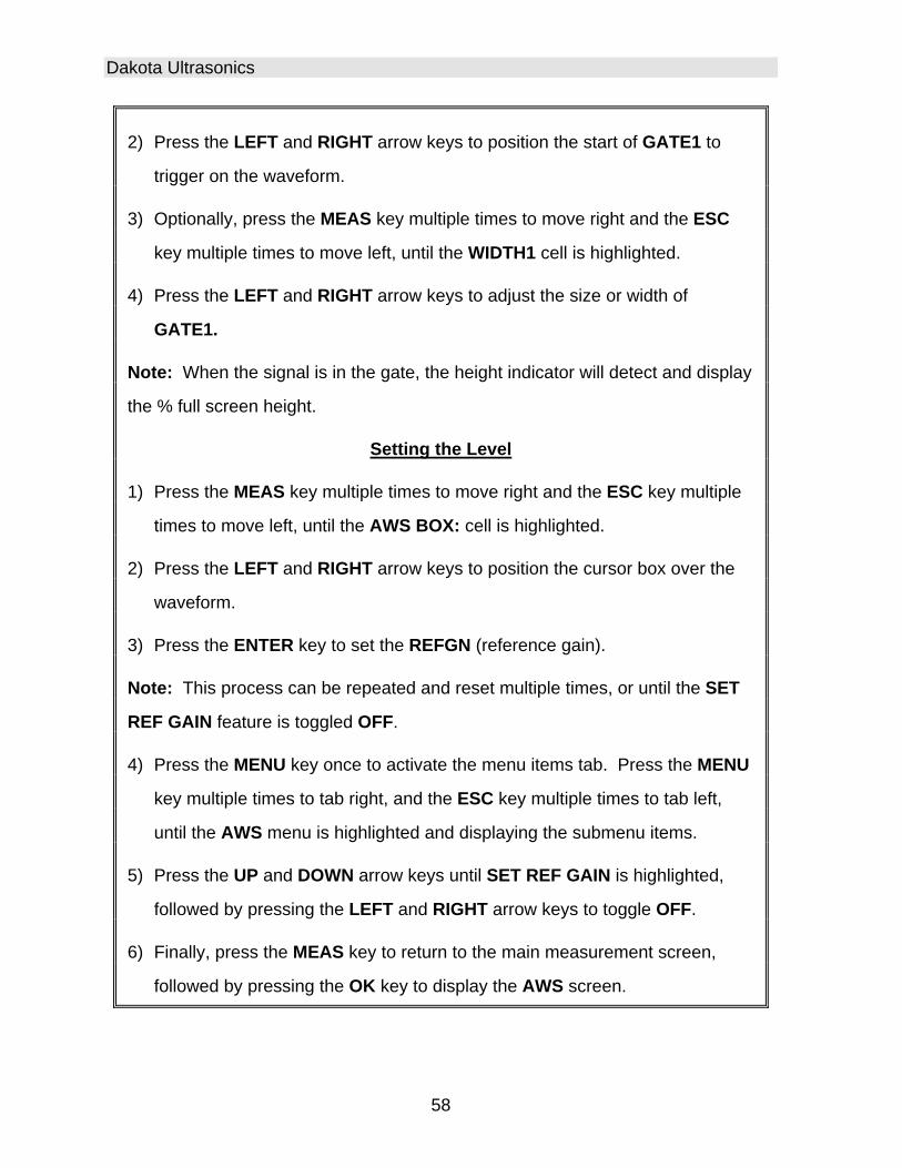
58
2) Press the LEFT and RIGHT arrow keys to position the start of GATE1 to
trigger on the waveform.
3) Optionally, press the MEAS key multiple times to move right and the ESC
key multiple times to move left, until the WIDTH1 cell is highlighted.
4) Press the LEFT and RIGHT arrow keys to adjust the size or width of
GATE1.
Note: When the signal is in the gate, the height indicator will detect and display
the % full screen height.
Setting the Level
1) Press the MEAS key multiple times to move right and the ESC key multiple
times to move left, until the AWS BOX: cell is highlighted.
2) Press the LEFT and RIGHT arrow keys to position the cursor box over the
waveform.
3) Press the ENTER key to set the REFGN (reference gain).
Note: This process can be repeated and reset multiple times, or until the SET
REF GAIN feature is toggled OFF.
4) Press the MENU key once to activate the menu items tab. Press the MENU
key multiple times to tab right, and the ESC key multiple times to tab left,
until the AWS menu is highlighted and displaying the submenu items.
5) Press the UP and DOWN arrow keys until SET REF GAIN is highlighted,
followed by pressing the LEFT and RIGHT arrow keys to toggle OFF.
6) Finally, press the MEAS key to return to the main measurement screen,
followed by pressing the OK key to display the AWS screen.
DFX-7 Ultrasonic Flaw Detector
59
Note: The AWS screen can be toggle on by pressing the OK key while in the
main measurement screen. Equally, the Hot Menus can be toggled by
pressing the MEAS at any time.
60
CHAPTER EIGHT DISTANCE AMPLITUDE CORRECTION (DAC)
8.1 Introduction to DAC A DAC curve is a gate with a variable threshold to compensate for a given reflector type and size measured at different depths. Unlike a standard gate, which typically has a fixed threshold level regardless of the depth, the DAC curve is more representative of the reflector size at different depths. In order to generate a DAC curve, calibration standards must made with the same material being inspected, the representative reflector size, and over a given thickness range. The DAC curve is then used as an alarm to inform the user about the size of any given reflector at any depth during the inspection process. Once the DAC curve has been established, the user can display; -2dB, -6dB, -10dB, -12dB, -6/-12dB, -6/-14dB, DAC or GATE at any time. The initial DAC curve generated is always displayed in conjunction with any of the above CURVE options. Additionally, the alarm can be set to TRIGGER on any of the curve options displayed. Therefore, if the -6/-12dB curve option has been selected, the user can toggle the TRIGGER options: GATE, DAC, -6dB, or -12dB. Note: Based on the screen resolution of the DFX-7, the dynamic range of the DAC is approximately 18dB. As a result, inspection of any materials that attenuate more than 18dB over the inspection range, the DAC feature should not be used, and TCG (Time Corrected Gain) should optionally be considered.
8.2 Additional Comments Prior to proceeding onto the next section to create a DAC curve, a few additional items will help with the users selection process in the menu items:
• Up to 8 points can be used to generate a DAC curve. • 3 or more points must be used in order to draw a DAC curve. • All the DAC curve or gate combinations only detect when the amplitude of the
signal is ‘at’ or ‘above’ the selected trigger option. • Any of the DAC curves or gate displayed, can be set as the trigger alarm
option. • The measure (meas) options are as follows:
dB – %DAC – At the DAC curve represents 100%. Any signal generating an amplitude below the DAC curve is less than 100%, and any above greater than 100%.

DFX-7 Ultrasonic Flaw Detector
61
%FSH – The top of the waveform display represents 100% full screen height. Any waveform amplitudes generated greater than 100% full screen height will not be displayed. 100% is the greatest value that can be displayed. Note: The MEAS option selected is overridden with %FSH while the DAC curve is in DRAW mode. Once the DRAW mode is turned off, the select MEAS option will be displayed.
• The MEAS, CURVE, and TRIGGER options can be changed at any time once the DAC curve has been created.
• In order to move the highlighted cursor over a waveform to use as a point in generating the DAC curve, the “DAC BOX:” hot menu item in the main measurement screen must be highlighted.
8.3 Creating a DAC Curve This section provides a step by step procedure to create a DAC curve. Note: a two point calibration should be done prior to proceeding. Refer to Chapter Five for the calibration procedures. Also, if the TRIG function will be used, it should be setup prior to proceeding. Refer to Chapter Six for the setup procedure.
Activating & Setting the Parameters
Activating DAC
1) Press the MENU key once to activate the menu items tab. Press the MENU
key multiple times to tab right, and the ESC key multiple times to tab left,
until the DAC menu is highlighted and displaying the submenu items.
Dakota Ultrasonics
62
2) Use the UP and DOWN arrow keys to scroll through the sub menu items
until DAC is highlighted.
3) Press the LEFT and RIGHT arrow keys to toggle the DAC feature ON or
AUDIBLE. The menu items should now become active and adjustable, as
illustrated above.
Activating Draw Mode
1) Press the UP and DOWN arrow keys until DRAW is highlighted, followed by
pressing the LEFT and RIGHT arrow keys until ON is displayed.
Quantity Displayed
1) Press the UP and DOWN arrow keys until MEAS is highlighted, followed by
pressing the LEFT and RIGHT arrow keys to toggle and select dB, %FSH,
or %DAC.
Selecting the Curve(s)
1) Press the UP and DOWN arrow keys until CURVE is highlighted, followed
by pressing the LEFT and RIGHT arrow keys to toggle and select DAC, -2, -
4, -6, -10, (-6/-12), or (-6/-14) curve options. The CURVE option can be
changed at any time after the DAC curve has been created.
Setting the Curve(s) Trigger
1) Press the UP and DOWN arrow keys until TRIGGER is highlighted, followed
by pressing the LEFT and RIGHT arrow keys to toggle and select which
curve or gate to use as the alarm trigger. The options displayed will vary
according to which CURVE option has been selected above: DAC, -2, -4, -6,
-10, (-6/-12), or (-6/-14) curve options. The Trigger option can be changed
at any time after the DAC curve has been created.
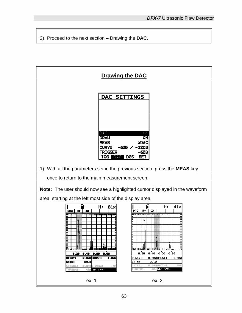
DFX-7 Ultrasonic Flaw Detector
63
2) Proceed to the next section – Drawing the DAC.
Drawing the DAC
1) With all the parameters set in the previous section, press the MEAS key
once to return to the main measurement screen.
Note: The user should now see a highlighted cursor displayed in the waveform
area, starting at the left most side of the display area.
ex. 1 ex. 2
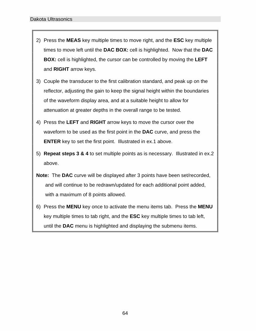
Dakota Ultrasonics
64
2) Press the MEAS key multiple times to move right, and the ESC key multiple
times to move left until the DAC BOX: cell is highlighted. Now that the DAC
BOX: cell is highlighted, the cursor can be controlled by moving the LEFT
and RIGHT arrow keys.
3) Couple the transducer to the first calibration standard, and peak up on the
reflector, adjusting the gain to keep the signal height within the boundaries
of the waveform display area, and at a suitable height to allow for
attenuation at greater depths in the overall range to be tested.
4) Press the LEFT and RIGHT arrow keys to move the cursor over the
waveform to be used as the first point in the DAC curve, and press the
ENTER key to set the first point. Illustrated in ex.1 above.
5) Repeat steps 3 & 4 to set multiple points as is necessary. Illustrated in ex.2
above.
Note: The DAC curve will be displayed after 3 points have been set/recorded,
and will continue to be redrawn/updated for each additional point added,
with a maximum of 8 points allowed.
6) Press the MENU key once to activate the menu items tab. Press the MENU
key multiple times to tab right, and the ESC key multiple times to tab left,
until the DAC menu is highlighted and displaying the submenu items.

DFX-7 Ultrasonic Flaw Detector
65
7) Press the UP and DOWN arrow keys until DRAW is highlighted, followed by
pressing the LEFT and RIGHT arrow keys until OFF is displayed. The DAC
curves are now set and ready to be used for inspection.
66
CHAPTER NINE TIME CORRECTED GAIN (TCG)
9.1 Introduction to TCG The TCG feature increases gain as distance increases, in order to achieve an overall level of sensitivity for the same reflector at different distances. It is very similar to the DAC feature noted in a previous chapter. However, while a DAC curve plots points at given amplitudes and distances, generating a variable threshold, the TCG feature increases the gain at various distances to adjust the signal amplitude to a predetermined level of full screen height. Therefore, the amplitude of all signals at various distances will be displayed at the same reference level. Note: One of the advantages of the TCG feature over the DAC option is the dynamic range. The TCG feature has a maximum dynamic range of 50dB, while the DAC option is approximately 18dB. Therefore the TCG feature is a better solution for any materials that attenuate more than 18dB over the inspection range, and should be considered.
9.2 Additional Comments Prior to proceeding onto the next section to create a DAC curve, a few additional items will help with the users selection process in the menu items:
• Up to 8 points can be used to generate a TCG curve. • 3 or more points must be used in order to draw a TCG curve. • The gain will be adjusted at each point to display the signal amplitude at a
predetermined reference level. • In order to move the highlighted cursor over a waveform to use as a point in
generating the TCG curve, the “TCG BOX:” hot menu item in the main measurement screen must be highlighted.
9.3 Creating a TCG Curve This section provides a step by step procedure to create a TCG curve. Note: a two point calibration should be done prior to proceeding. Refer to Chapter Five for the calibration procedures. Also, if the TRIG function will be used, it should be setup prior to proceeding. Refer to Chapter Six for the setup procedure.
Setting TCG Parameters
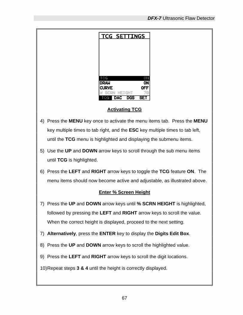
DFX-7 Ultrasonic Flaw Detector
67
Activating TCG
4) Press the MENU key once to activate the menu items tab. Press the MENU
key multiple times to tab right, and the ESC key multiple times to tab left,
until the TCG menu is highlighted and displaying the submenu items.
5) Use the UP and DOWN arrow keys to scroll through the sub menu items
until TCG is highlighted.
6) Press the LEFT and RIGHT arrow keys to toggle the TCG feature ON. The
menu items should now become active and adjustable, as illustrated above.
Enter % Screen Height
7) Press the UP and DOWN arrow keys until % SCRN HEIGHT is highlighted,
followed by pressing the LEFT and RIGHT arrow keys to scroll the value.
When the correct height is displayed, proceed to the next setting.
7) Alternatively, press the ENTER key to display the Digits Edit Box.
8) Press the UP and DOWN arrow keys to scroll the highlighted value.
9) Press the LEFT and RIGHT arrow keys to scroll the digit locations.
10) Repeat steps 3 & 4 until the height is correctly displayed.
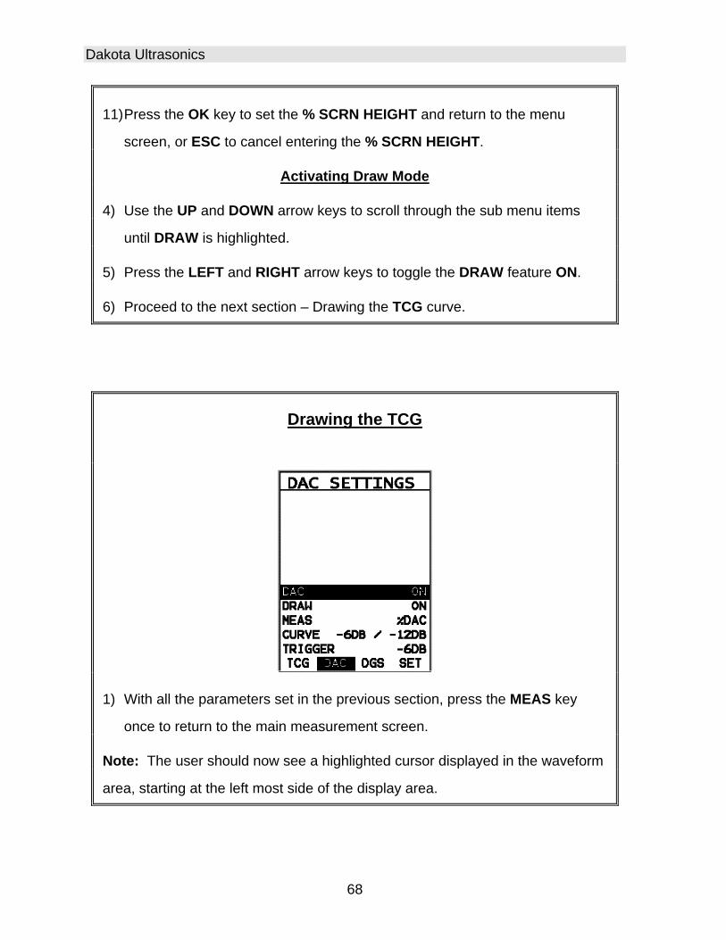
Dakota Ultrasonics
68
11) Press the OK key to set the % SCRN HEIGHT and return to the menu
screen, or ESC to cancel entering the % SCRN HEIGHT.
Activating Draw Mode
4) Use the UP and DOWN arrow keys to scroll through the sub menu items
until DRAW is highlighted.
5) Press the LEFT and RIGHT arrow keys to toggle the DRAW feature ON.
6) Proceed to the next section – Drawing the TCG curve.
Drawing the TCG
1) With all the parameters set in the previous section, press the MEAS key
once to return to the main measurement screen.
Note: The user should now see a highlighted cursor displayed in the waveform
area, starting at the left most side of the display area.
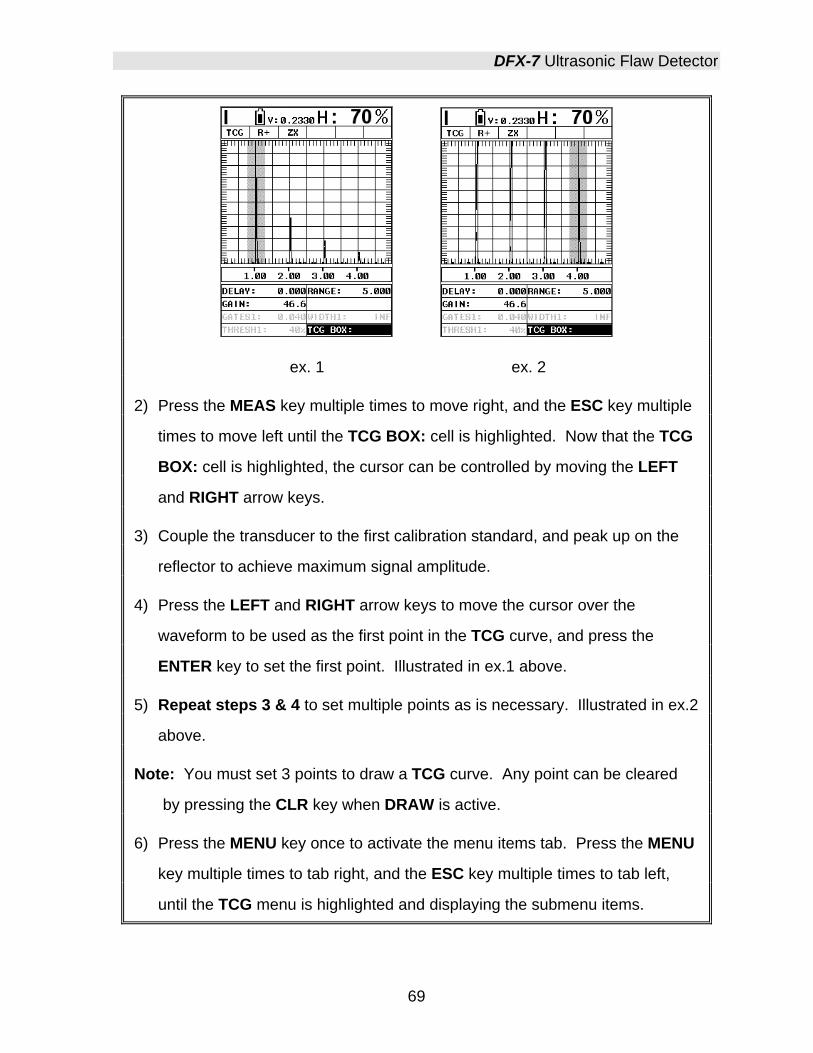
DFX-7 Ultrasonic Flaw Detector
69
ex. 1 ex. 2
2) Press the MEAS key multiple times to move right, and the ESC key multiple
times to move left until the TCG BOX: cell is highlighted. Now that the TCG
BOX: cell is highlighted, the cursor can be controlled by moving the LEFT
and RIGHT arrow keys.
3) Couple the transducer to the first calibration standard, and peak up on the
reflector to achieve maximum signal amplitude.
4) Press the LEFT and RIGHT arrow keys to move the cursor over the
waveform to be used as the first point in the TCG curve, and press the
ENTER key to set the first point. Illustrated in ex.1 above.
5) Repeat steps 3 & 4 to set multiple points as is necessary. Illustrated in ex.2
above.
Note: You must set 3 points to draw a TCG curve. Any point can be cleared
by pressing the CLR key when DRAW is active.
6) Press the MENU key once to activate the menu items tab. Press the MENU
key multiple times to tab right, and the ESC key multiple times to tab left,
until the TCG menu is highlighted and displaying the submenu items.
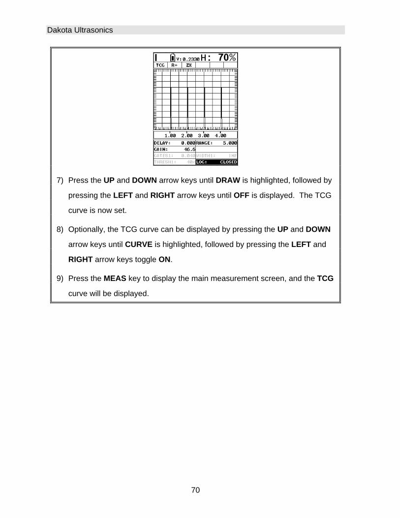
Dakota Ultrasonics
70
7) Press the UP and DOWN arrow keys until DRAW is highlighted, followed by
pressing the LEFT and RIGHT arrow keys until OFF is displayed. The TCG
curve is now set.
8) Optionally, the TCG curve can be displayed by pressing the UP and DOWN
arrow keys until CURVE is highlighted, followed by pressing the LEFT and
RIGHT arrow keys toggle ON.
9) Press the MEAS key to display the main measurement screen, and the TCG
curve will be displayed.
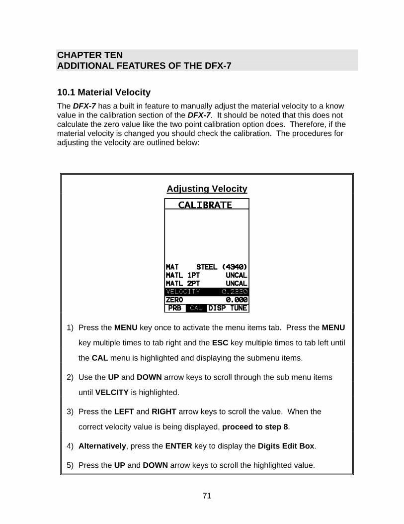
71
CHAPTER TEN ADDITIONAL FEATURES OF THE DFX-7
10.1 Material Velocity The DFX-7 has a built in feature to manually adjust the material velocity to a know value in the calibration section of the DFX-7. It should be noted that this does not calculate the zero value like the two point calibration option does. Therefore, if the material velocity is changed you should check the calibration. The procedures for adjusting the velocity are outlined below:
Adjusting Velocity
1) Press the MENU key once to activate the menu items tab. Press the MENU
key multiple times to tab right and the ESC key multiple times to tab left until
the CAL menu is highlighted and displaying the submenu items.
2) Use the UP and DOWN arrow keys to scroll through the sub menu items
until VELCITY is highlighted.
3) Press the LEFT and RIGHT arrow keys to scroll the value. When the
correct velocity value is being displayed, proceed to step 8.
4) Alternatively, press the ENTER key to display the Digits Edit Box.
5) Press the UP and DOWN arrow keys to scroll the highlighted value.
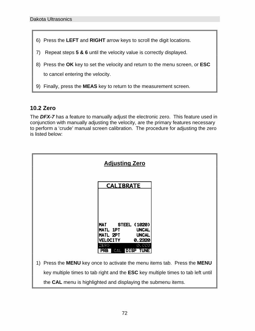
Dakota Ultrasonics
72
6) Press the LEFT and RIGHT arrow keys to scroll the digit locations.
7) Repeat steps 5 & 6 until the velocity value is correctly displayed.
8) Press the OK key to set the velocity and return to the menu screen, or ESC
to cancel entering the velocity.
9) Finally, press the MEAS key to return to the measurement screen.
10.2 Zero The DFX-7 has a feature to manually adjust the electronic zero. This feature used in conjunction with manually adjusting the velocity, are the primary features necessary to perform a ‘crude’ manual screen calibration. The procedure for adjusting the zero is listed below:
Adjusting Zero
1) Press the MENU key once to activate the menu items tab. Press the MENU
key multiple times to tab right and the ESC key multiple times to tab left until
the CAL menu is highlighted and displaying the submenu items.
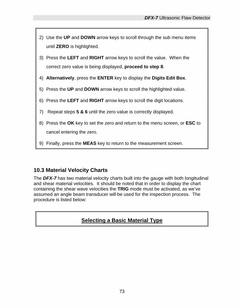
DFX-7 Ultrasonic Flaw Detector
73
2) Use the UP and DOWN arrow keys to scroll through the sub menu items
until ZERO is highlighted.
3) Press the LEFT and RIGHT arrow keys to scroll the value. When the
correct zero value is being displayed, proceed to step 8.
4) Alternatively, press the ENTER key to display the Digits Edit Box.
5) Press the UP and DOWN arrow keys to scroll the highlighted value.
6) Press the LEFT and RIGHT arrow keys to scroll the digit locations.
7) Repeat steps 5 & 6 until the zero value is correctly displayed.
8) Press the OK key to set the zero and return to the menu screen, or ESC to
cancel entering the zero.
9) Finally, press the MEAS key to return to the measurement screen.
10.3 Material Velocity Charts The DFX-7 has two material velocity charts built into the gauge with both longitudinal and shear material velocities. It should be noted that in order to display the chart containing the shear wave velocities the TRIG mode must be activated, as we’ve assumed an angle beam transducer will be used for the inspection process. The procedure is listed below:
Selecting a Basic Material Type
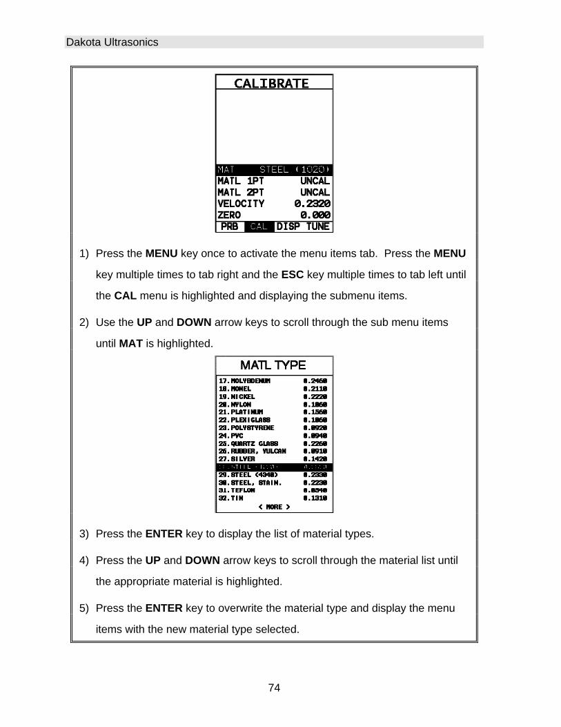
Dakota Ultrasonics
74
1) Press the MENU key once to activate the menu items tab. Press the MENU
key multiple times to tab right and the ESC key multiple times to tab left until
the CAL menu is highlighted and displaying the submenu items.
2) Use the UP and DOWN arrow keys to scroll through the sub menu items
until MAT is highlighted.
3) Press the ENTER key to display the list of material types.
4) Press the UP and DOWN arrow keys to scroll through the material list until
the appropriate material is highlighted.
5) Press the ENTER key to overwrite the material type and display the menu
items with the new material type selected.
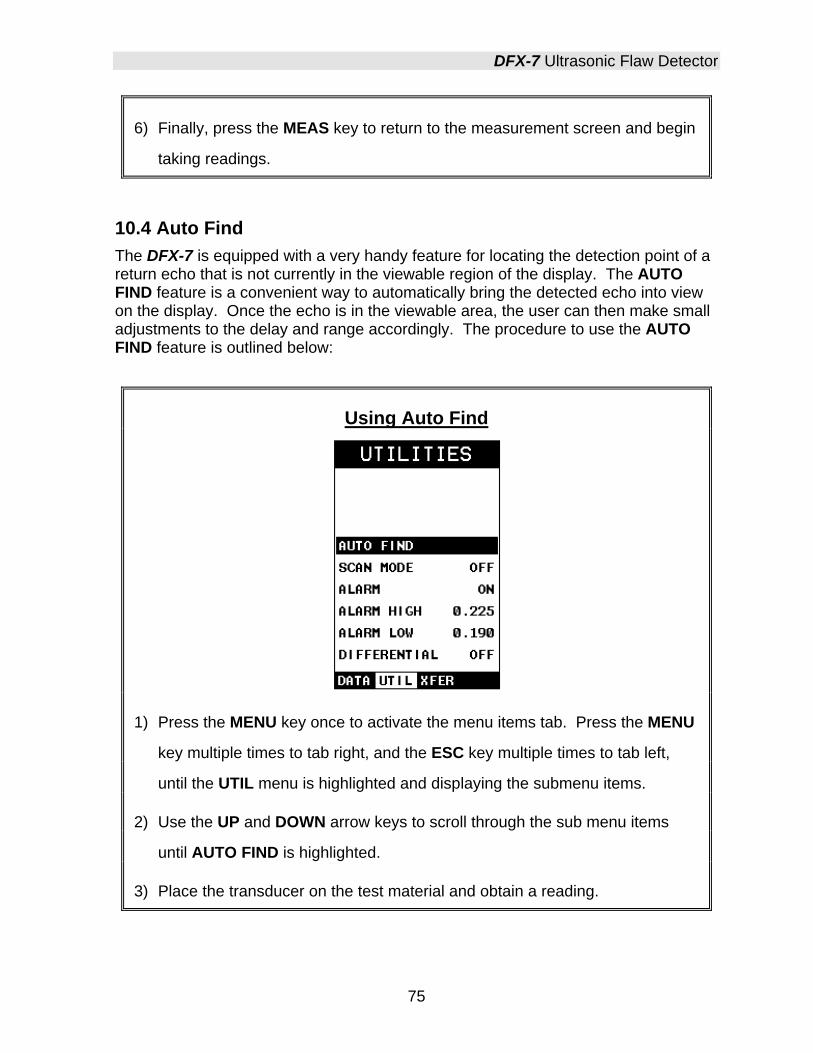
DFX-7 Ultrasonic Flaw Detector
75
6) Finally, press the MEAS key to return to the measurement screen and begin
taking readings.
10.4 Auto Find The DFX-7 is equipped with a very handy feature for locating the detection point of a return echo that is not currently in the viewable region of the display. The AUTO FIND feature is a convenient way to automatically bring the detected echo into view on the display. Once the echo is in the viewable area, the user can then make small adjustments to the delay and range accordingly. The procedure to use the AUTO FIND feature is outlined below:
Using Auto Find
1) Press the MENU key once to activate the menu items tab. Press the MENU
key multiple times to tab right, and the ESC key multiple times to tab left,
until the UTIL menu is highlighted and displaying the submenu items.
2) Use the UP and DOWN arrow keys to scroll through the sub menu items
until AUTO FIND is highlighted.
3) Place the transducer on the test material and obtain a reading.
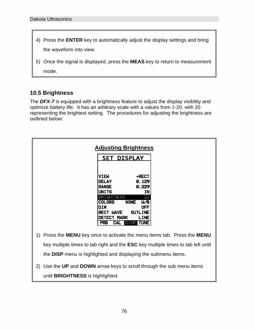
Dakota Ultrasonics
76
4) Press the ENTER key to automatically adjust the display settings and bring
the waveform into view.
5) Once the signal is displayed, press the MEAS key to return to measurement
mode.
10.5 Brightness The DFX-7 is equipped with a brightness feature to adjust the display visibility and optimize battery life. It has an arbitrary scale with a values from 1-20, with 20 representing the brightest setting. The procedures for adjusting the brightness are outlined below:
Adjusting Brightness
1) Press the MENU key once to activate the menu items tab. Press the MENU
key multiple times to tab right and the ESC key multiple times to tab left until
the DISP menu is highlighted and displaying the submenu items.
2) Use the UP and DOWN arrow keys to scroll through the sub menu items
until BRIGHTNESS is highlighted.
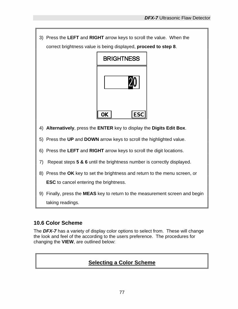
DFX-7 Ultrasonic Flaw Detector
77
3) Press the LEFT and RIGHT arrow keys to scroll the value. When the
correct brightness value is being displayed, proceed to step 8.
4) Alternatively, press the ENTER key to display the Digits Edit Box.
5) Press the UP and DOWN arrow keys to scroll the highlighted value.
6) Press the LEFT and RIGHT arrow keys to scroll the digit locations.
7) Repeat steps 5 & 6 until the brightness number is correctly displayed.
8) Press the OK key to set the brightness and return to the menu screen, or
ESC to cancel entering the brightness.
9) Finally, press the MEAS key to return to the measurement screen and begin
taking readings.
10.6 Color Scheme The DFX-7 has a variety of display color options to select from. These will change the look and feel of the according to the users preference. The procedures for changing the VIEW, are outlined below:
Selecting a Color Scheme
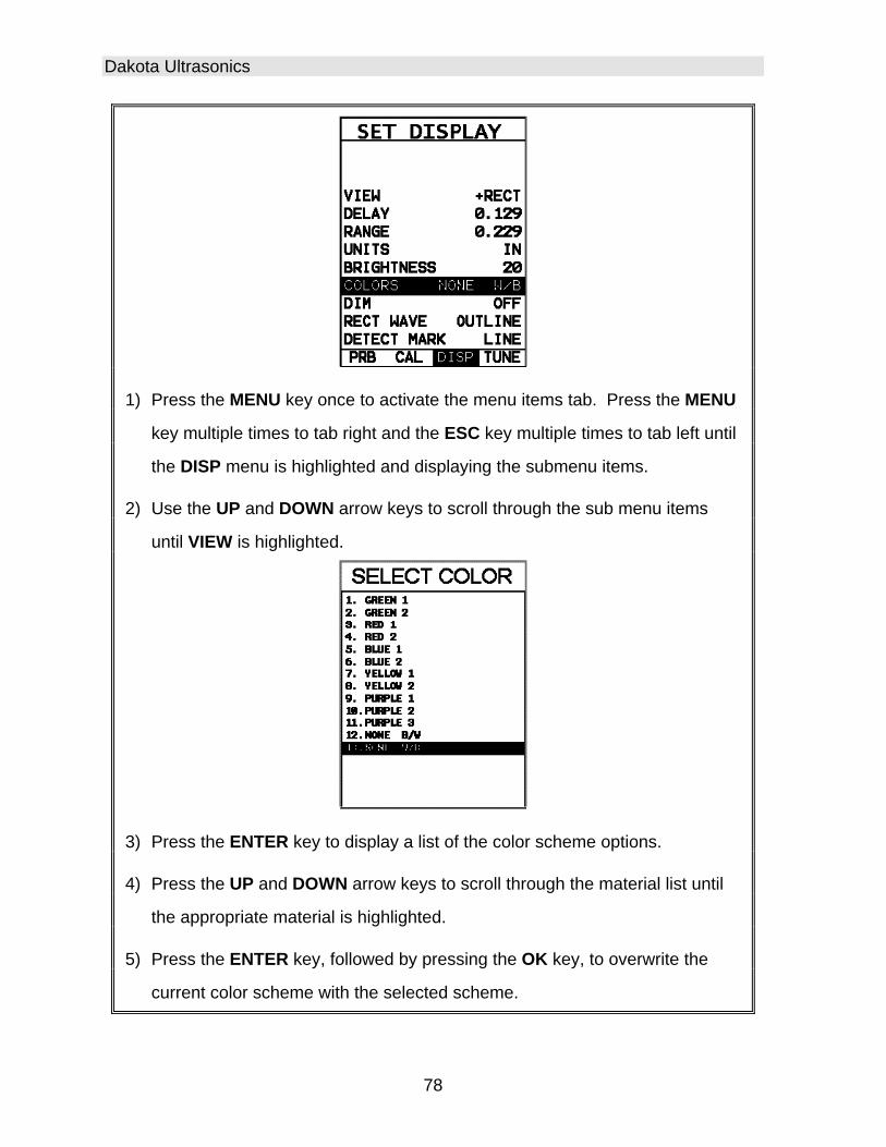
Dakota Ultrasonics
78
1) Press the MENU key once to activate the menu items tab. Press the MENU
key multiple times to tab right and the ESC key multiple times to tab left until
the DISP menu is highlighted and displaying the submenu items.
2) Use the UP and DOWN arrow keys to scroll through the sub menu items
until VIEW is highlighted.
3) Press the ENTER key to display a list of the color scheme options.
4) Press the UP and DOWN arrow keys to scroll through the material list until
the appropriate material is highlighted.
5) Press the ENTER key, followed by pressing the OK key, to overwrite the
current color scheme with the selected scheme.
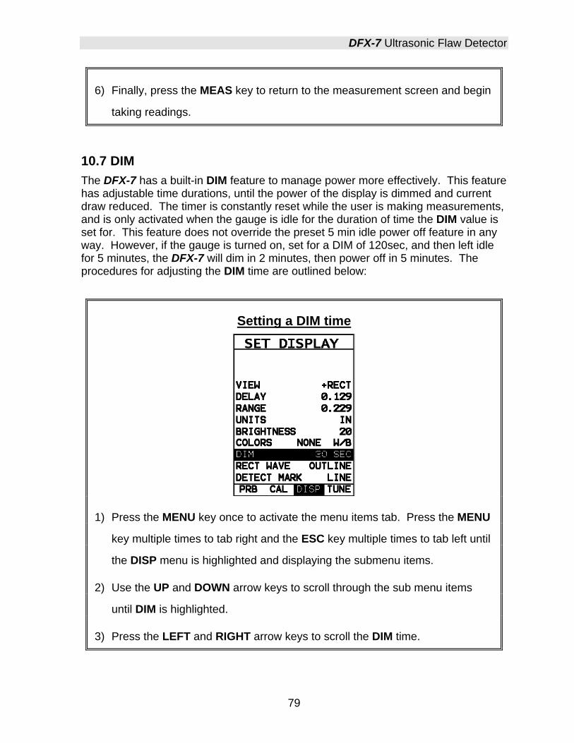
DFX-7 Ultrasonic Flaw Detector
79
6) Finally, press the MEAS key to return to the measurement screen and begin
taking readings.
10.7 DIM The DFX-7 has a built-in DIM feature to manage power more effectively. This feature has adjustable time durations, until the power of the display is dimmed and current draw reduced. The timer is constantly reset while the user is making measurements, and is only activated when the gauge is idle for the duration of time the DIM value is set for. This feature does not override the preset 5 min idle power off feature in any way. However, if the gauge is turned on, set for a DIM of 120sec, and then left idle for 5 minutes, the DFX-7 will dim in 2 minutes, then power off in 5 minutes. The procedures for adjusting the DIM time are outlined below:
Setting a DIM time
1) Press the MENU key once to activate the menu items tab. Press the MENU
key multiple times to tab right and the ESC key multiple times to tab left until
the DISP menu is highlighted and displaying the submenu items.
2) Use the UP and DOWN arrow keys to scroll through the sub menu items
until DIM is highlighted.
3) Press the LEFT and RIGHT arrow keys to scroll the DIM time.
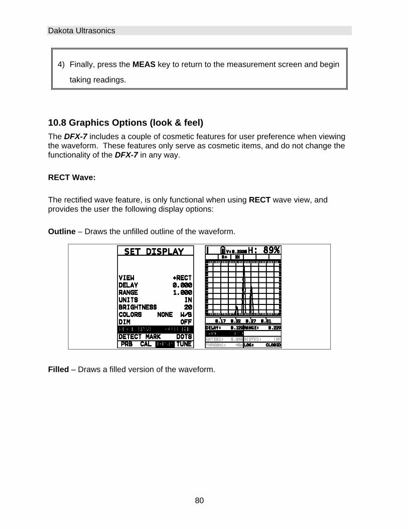
Dakota Ultrasonics
80
4) Finally, press the MEAS key to return to the measurement screen and begin
taking readings.
10.8 Graphics Options (look & feel) The DFX-7 includes a couple of cosmetic features for user preference when viewing the waveform. These features only serve as cosmetic items, and do not change the functionality of the DFX-7 in any way. RECT Wave: The rectified wave feature, is only functional when using RECT wave view, and provides the user the following display options: Outline – Draws the unfilled outline of the waveform.
Filled – Draws a filled version of the waveform.
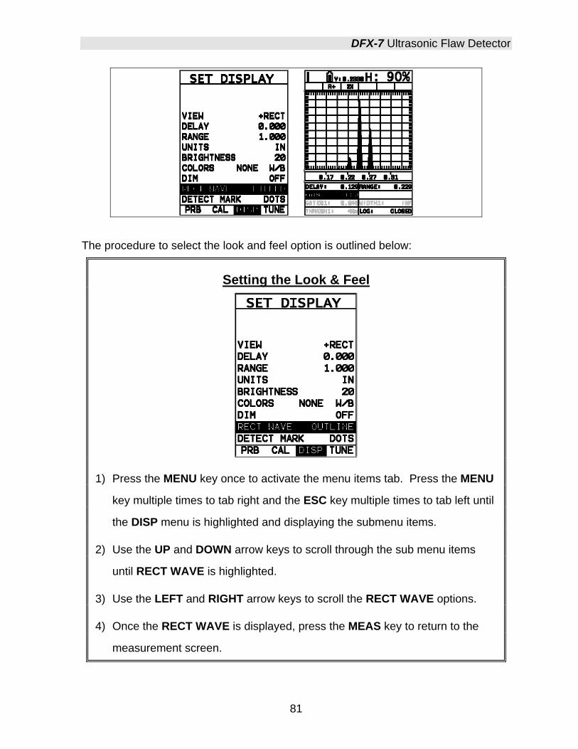
DFX-7 Ultrasonic Flaw Detector
81
The procedure to select the look and feel option is outlined below:
Setting the Look & Feel
1) Press the MENU key once to activate the menu items tab. Press the MENU
key multiple times to tab right and the ESC key multiple times to tab left until
the DISP menu is highlighted and displaying the submenu items.
2) Use the UP and DOWN arrow keys to scroll through the sub menu items
until RECT WAVE is highlighted.
3) Use the LEFT and RIGHT arrow keys to scroll the RECT WAVE options.
4) Once the RECT WAVE is displayed, press the MEAS key to return to the
measurement screen.

Dakota Ultrasonics
82
10.9 Detect Mark Another look and feel option of the DFX-7 is the DETECT MARK feature. The detect mark give the user the option to select: none, line, dots, or box. Depending on the select made, an indication will be displayed on the waveform, showing where the detection is occurring. It should be noted that the “box” option will only be visible in RF view. The following screenshots illustrate the above selection options:
None Line
Dots Box
10.10 Polarity The DFX-7 has a number of features and views that offer selectable polarity. The important thing to note is the polarity view is entirely different than the polarity selection of a gate. If a polarity view of +RECT is selected, only the positive portion of the waveform will be shown on the screen. If a positive polarity is then selected for GT1, not only will the gate be displayed on the screen, it will only detect on the positive going cycles of the waveform. Polarity is selectable according to the VIEW, GT1, GT2, and DAC. Again, view corresponds only to what portion of the waveform is displayed, positive or negative, and the other three options are primarily associated with where the detect occurs. Finally, if the view is set to RF, the entire waveform cycle will be displayed, both positive and negative. Refer to the diagram below:
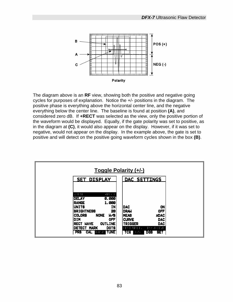
DFX-7 Ultrasonic Flaw Detector
83
The diagram above is an RF view, showing both the positive and negative going cycles for purposes of explanation. Notice the +/- positions in the diagram. The positive phase is everything above the horizontal center line, and the negative everything below the center line. The baseline is found at position (A), and considered zero dB. If +RECT was selected as the view, only the positive portion of the waveform would be displayed. Equally, if the gate polarity was set to positive, as in the diagram at (C), it would also appear on the display. However, if it was set to negative, would not appear on the display. In the example above, the gate is set to positive and will detect on the positive going waveform cycles shown in the box (B).
Toggle Polarity (+/-)
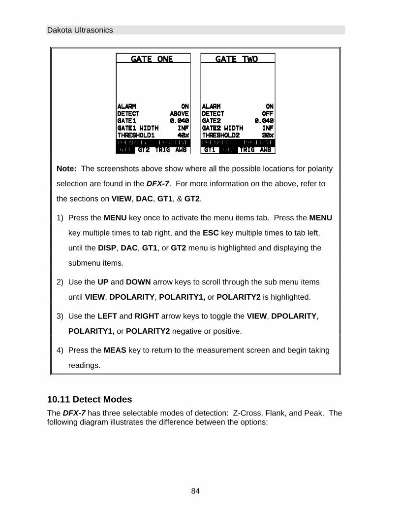
Dakota Ultrasonics
84
Note: The screenshots above show where all the possible locations for polarity
selection are found in the DFX-7. For more information on the above, refer to
the sections on VIEW, DAC, GT1, & GT2.
1) Press the MENU key once to activate the menu items tab. Press the MENU
key multiple times to tab right, and the ESC key multiple times to tab left,
until the DISP, DAC, GT1, or GT2 menu is highlighted and displaying the
submenu items.
2) Use the UP and DOWN arrow keys to scroll through the sub menu items
until VIEW, DPOLARITY, POLARITY1, or POLARITY2 is highlighted.
3) Use the LEFT and RIGHT arrow keys to toggle the VIEW, DPOLARITY,
POLARITY1, or POLARITY2 negative or positive.
4) Press the MEAS key to return to the measurement screen and begin taking
readings.
10.11 Detect Modes The DFX-7 has three selectable modes of detection: Z-Cross, Flank, and Peak. The following diagram illustrates the difference between the options:

DFX-7 Ultrasonic Flaw Detector
85
Z-Cross Flank Peak
Refer to the diagrams above. The current polarity is positive, as shown by the position of the gate above the baseline: Z-Cross: The detection occurs as the first positive half cycle crosses the baseline and goes negative. Flank: The detection occurs as the first half cycle left edge rises and breaks the threshold. Peak: The detection occurs at the highest peak in the gate. The procedure to select the DETECT MODE is outlined below:
Selecting the Detect
5) Press the MENU key once to activate the menu items tab. Press the MENU
key multiple times to tab right and the ESC key multiple times to tab left until
the TUNE menu is highlighted and displaying the submenu items.
6) Use the UP and DOWN arrow keys to scroll through the sub menu items
until DETECT MODE is highlighted.
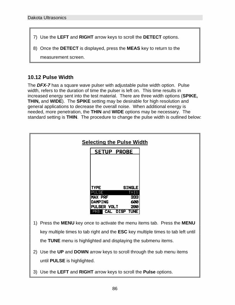
Dakota Ultrasonics
86
7) Use the LEFT and RIGHT arrow keys to scroll the DETECT options.
8) Once the DETECT is displayed, press the MEAS key to return to the
measurement screen.
10.12 Pulse Width The DFX-7 has a square wave pulser with adjustable pulse width option. Pulse width, refers to the duration of time the pulser is left on. This time results in increased energy sent into the test material. There are three width options (SPIKE, THIN, and WIDE). The SPIKE setting may be desirable for high resolution and general applications to decrease the overall noise. When additional energy is needed, more penetration, the THIN and WIDE options may be necessary. The standard setting is THIN. The procedure to change the pulse width is outlined below:
Selecting the Pulse Width
1) Press the MENU key once to activate the menu items tab. Press the MENU
key multiple times to tab right and the ESC key multiple times to tab left until
the TUNE menu is highlighted and displaying the submenu items.
2) Use the UP and DOWN arrow keys to scroll through the sub menu items
until PULSE is highlighted.
3) Use the LEFT and RIGHT arrow keys to scroll the Pulse options.
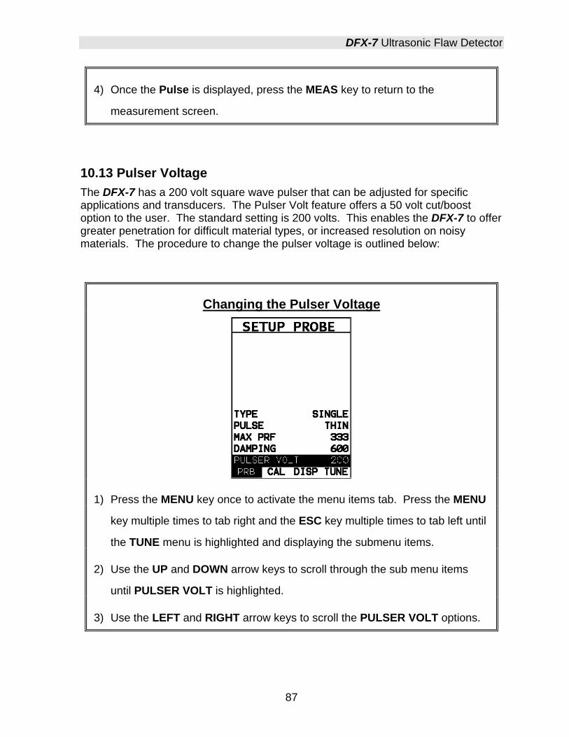
DFX-7 Ultrasonic Flaw Detector
87
4) Once the Pulse is displayed, press the MEAS key to return to the
measurement screen.
10.13 Pulser Voltage The DFX-7 has a 200 volt square wave pulser that can be adjusted for specific applications and transducers. The Pulser Volt feature offers a 50 volt cut/boost option to the user. The standard setting is 200 volts. This enables the DFX-7 to offer greater penetration for difficult material types, or increased resolution on noisy materials. The procedure to change the pulser voltage is outlined below:
Changing the Pulser Voltage
1) Press the MENU key once to activate the menu items tab. Press the MENU
key multiple times to tab right and the ESC key multiple times to tab left until
the TUNE menu is highlighted and displaying the submenu items.
2) Use the UP and DOWN arrow keys to scroll through the sub menu items
until PULSER VOLT is highlighted.
3) Use the LEFT and RIGHT arrow keys to scroll the PULSER VOLT options.
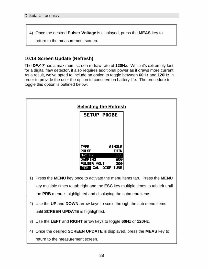
Dakota Ultrasonics
88
4) Once the desired Pulser Voltage is displayed, press the MEAS key to
return to the measurement screen.
10.14 Screen Update (Refresh) The DFX-7 has a maximum screen redraw rate of 120Hz. While it’s extremely fast for a digital flaw detector, it also requires additional power as it draws more current. As a result, we’ve opted to include an option to toggle between 60Hz and 120Hz in order to provide the user the option to conserve on battery life. The procedure to toggle this option is outlined below:
Selecting the Refresh
1) Press the MENU key once to activate the menu items tab. Press the MENU
key multiple times to tab right and the ESC key multiple times to tab left until
the PRB menu is highlighted and displaying the submenu items.
2) Use the UP and DOWN arrow keys to scroll through the sub menu items
until SCREEN UPDATE is highlighted.
3) Use the LEFT and RIGHT arrow keys to toggle 60Hz or 120Hz.
4) Once the desired SCREEN UPDATE is displayed, press the MEAS key to
return to the measurement screen.
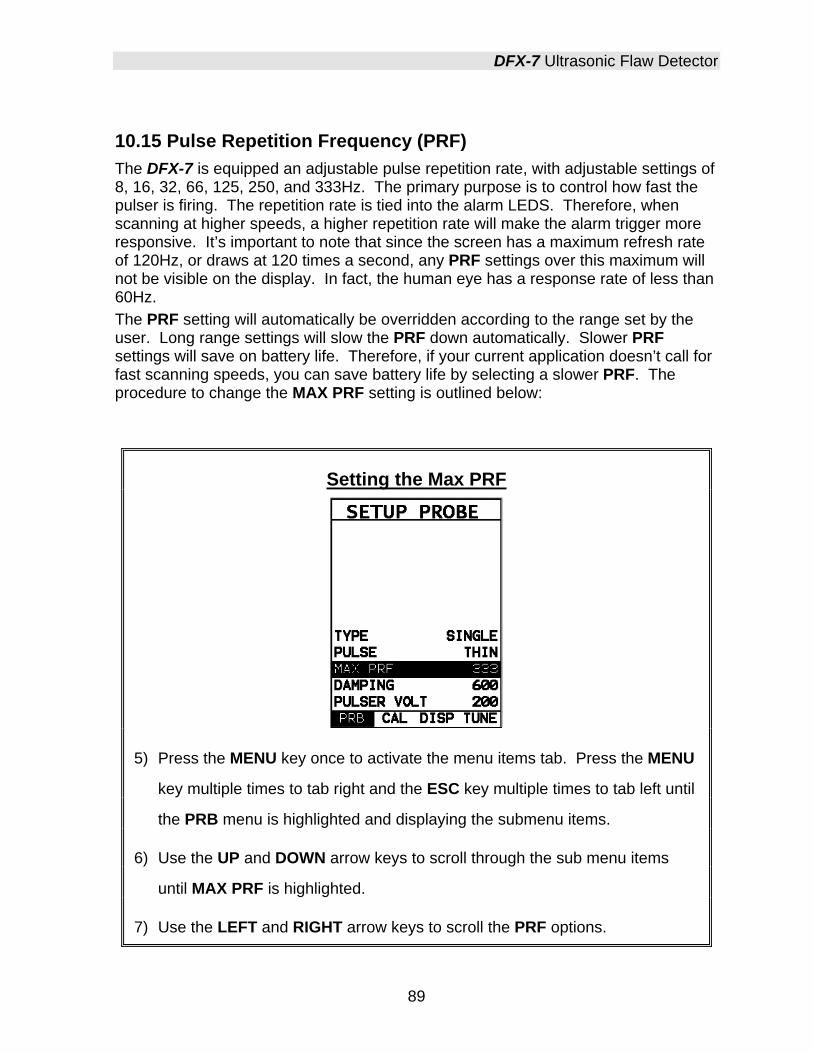
DFX-7 Ultrasonic Flaw Detector
89
10.15 Pulse Repetition Frequency (PRF) The DFX-7 is equipped an adjustable pulse repetition rate, with adjustable settings of 8, 16, 32, 66, 125, 250, and 333Hz. The primary purpose is to control how fast the pulser is firing. The repetition rate is tied into the alarm LEDS. Therefore, when scanning at higher speeds, a higher repetition rate will make the alarm trigger more responsive. It’s important to note that since the screen has a maximum refresh rate of 120Hz, or draws at 120 times a second, any PRF settings over this maximum will not be visible on the display. In fact, the human eye has a response rate of less than 60Hz. The PRF setting will automatically be overridden according to the range set by the user. Long range settings will slow the PRF down automatically. Slower PRF settings will save on battery life. Therefore, if your current application doesn’t call for fast scanning speeds, you can save battery life by selecting a slower PRF. The procedure to change the MAX PRF setting is outlined below:
Setting the Max PRF
5) Press the MENU key once to activate the menu items tab. Press the MENU
key multiple times to tab right and the ESC key multiple times to tab left until
the PRB menu is highlighted and displaying the submenu items.
6) Use the UP and DOWN arrow keys to scroll through the sub menu items
until MAX PRF is highlighted.
7) Use the LEFT and RIGHT arrow keys to scroll the PRF options.
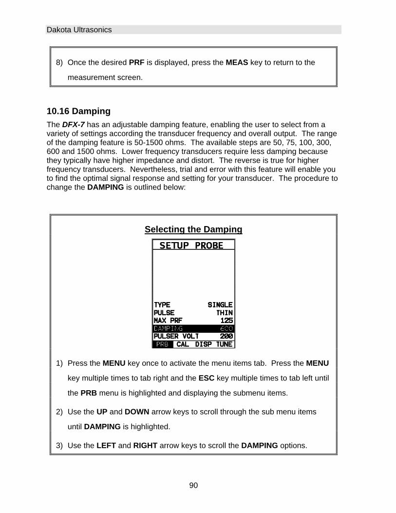
Dakota Ultrasonics
90
8) Once the desired PRF is displayed, press the MEAS key to return to the
measurement screen.
10.16 Damping The DFX-7 has an adjustable damping feature, enabling the user to select from a variety of settings according the transducer frequency and overall output. The range of the damping feature is 50-1500 ohms. The available steps are 50, 75, 100, 300, 600 and 1500 ohms. Lower frequency transducers require less damping because they typically have higher impedance and distort. The reverse is true for higher frequency transducers. Nevertheless, trial and error with this feature will enable you to find the optimal signal response and setting for your transducer. The procedure to change the DAMPING is outlined below:
Selecting the Damping
1) Press the MENU key once to activate the menu items tab. Press the MENU
key multiple times to tab right and the ESC key multiple times to tab left until
the PRB menu is highlighted and displaying the submenu items.
2) Use the UP and DOWN arrow keys to scroll through the sub menu items
until DAMPING is highlighted.
3) Use the LEFT and RIGHT arrow keys to scroll the DAMPING options.
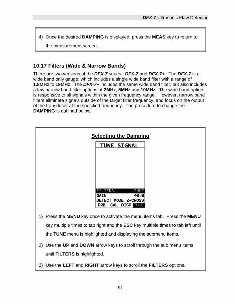
DFX-7 Ultrasonic Flaw Detector
91
4) Once the desired DAMPING is displayed, press the MEAS key to return to
the measurement screen.
10.17 Filters (Wide & Narrow Bands) There are two versions of the DFX-7 series: DFX-7 and DFX-7+. The DFX-7 is a wide band only gauge, which includes a single wide band filter with a range of 1.8MHz to 19MHz. The DFX-7+ includes the same wide band filter, but also includes a few narrow band filter options at 2MHz, 5MHz and 10MHz. The wide band option is responsive to all signals within the given frequency range. However, narrow band filters eliminate signals outside of the target filter frequency, and focus on the output of the transducer at the specified frequency. The procedure to change the DAMPING is outlined below:
Selecting the Damping
1) Press the MENU key once to activate the menu items tab. Press the MENU
key multiple times to tab right and the ESC key multiple times to tab left until
the TUNE menu is highlighted and displaying the submenu items.
2) Use the UP and DOWN arrow keys to scroll through the sub menu items
until FILTERS is highlighted.
3) Use the LEFT and RIGHT arrow keys to scroll the FILTERS options.

Dakota Ultrasonics
92
4) Once the desired FILTERS is displayed, press the MEAS key to return to
the measurement screen.
10.18 Peak Hold The DFX-7 includes a peak hold feature that draws and saves the maximum waveform amplitude on the screen. This allows an inspector to move the transducer in all directions, in an effort to “peak up” on a signal, and locate the maximum amplitude. The following procure outlines the steps to activate and use the PEAK hold feature:
Activating Peak
1) Press the MULTI MODE key located in the bottom left corner of the keypad
to display the mode options.
2) Use the UP and DOWN arrow keys PEAK is highlighted.
3) Press the MEAS key to return to the measurement screen.
Clearing Current Wave Draw
Note: At any point during a PEAK scan the operator may opt to clear the wave
drawing and start over.
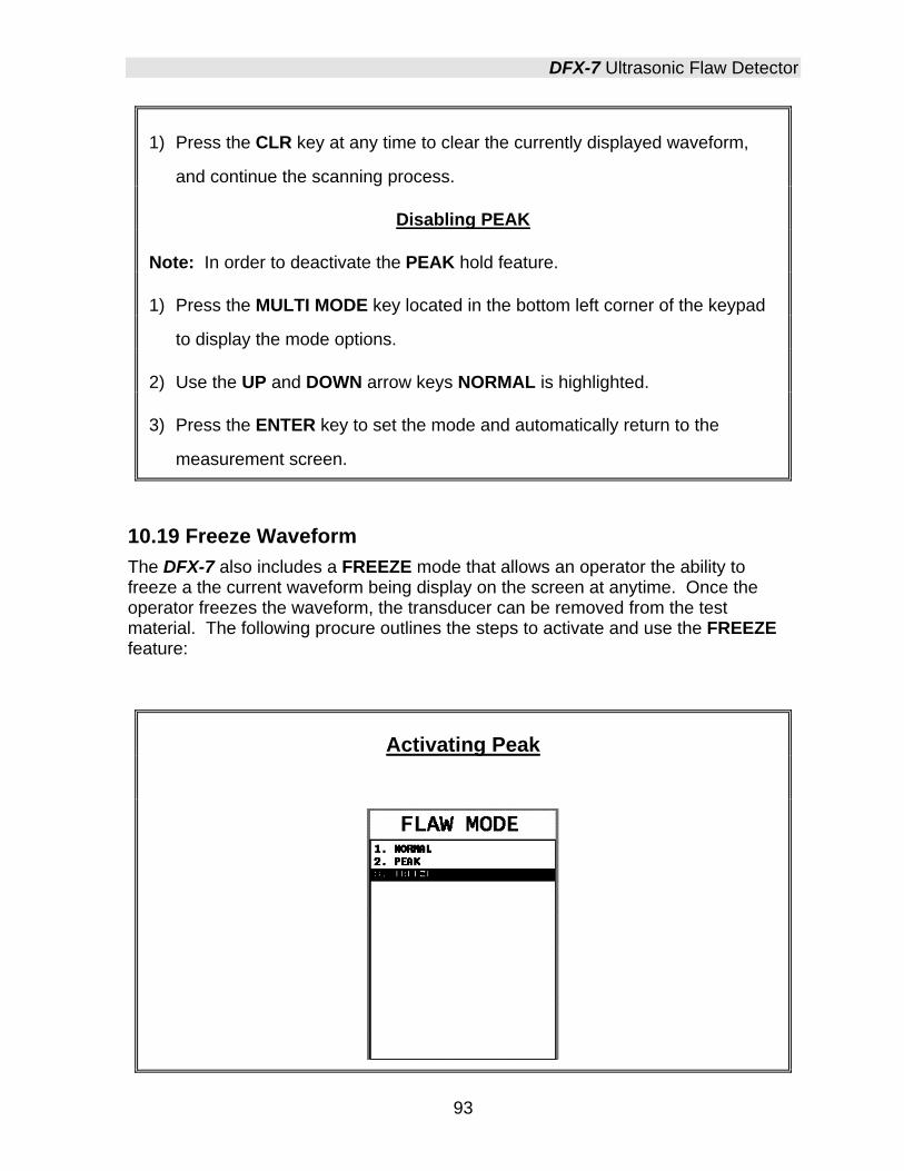
DFX-7 Ultrasonic Flaw Detector
93
1) Press the CLR key at any time to clear the currently displayed waveform,
and continue the scanning process.
Disabling PEAK
Note: In order to deactivate the PEAK hold feature.
1) Press the MULTI MODE key located in the bottom left corner of the keypad
to display the mode options.
2) Use the UP and DOWN arrow keys NORMAL is highlighted.
3) Press the ENTER key to set the mode and automatically return to the
measurement screen.
10.19 Freeze Waveform The DFX-7 also includes a FREEZE mode that allows an operator the ability to freeze a the current waveform being display on the screen at anytime. Once the operator freezes the waveform, the transducer can be removed from the test material. The following procure outlines the steps to activate and use the FREEZE feature:
Activating Peak
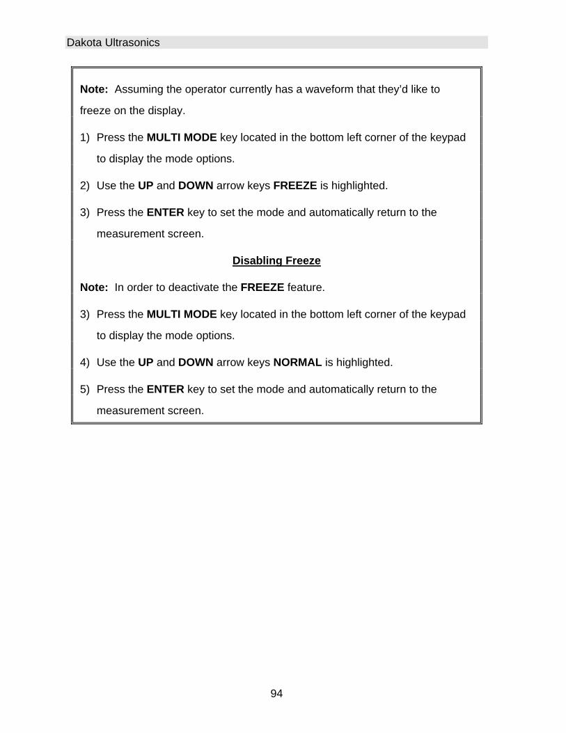
Dakota Ultrasonics
94
Note: Assuming the operator currently has a waveform that they’d like to
freeze on the display.
1) Press the MULTI MODE key located in the bottom left corner of the keypad
to display the mode options.
2) Use the UP and DOWN arrow keys FREEZE is highlighted.
3) Press the ENTER key to set the mode and automatically return to the
measurement screen.
Disabling Freeze
Note: In order to deactivate the FREEZE feature.
3) Press the MULTI MODE key located in the bottom left corner of the keypad
to display the mode options.
4) Use the UP and DOWN arrow keys NORMAL is highlighted.
5) Press the ENTER key to set the mode and automatically return to the
measurement screen.
95
CHAPTER ELEVEN DATA STORAGE – SETUP, EDIT, & VIEW FILES
11.1 Introduction to Grid and Sequential file formats The DFX-7 is equipped with two data file format options, GRID LOG and SEQ LOG. The GRID file format is very similar to a spreadsheet format found in popular software programs like Excel. A GRID is simply a table of readings. A location in a grid is specified by giving a row and column coordinate. The rows are numbered from 1 to 999 and the columns are labeled from A to ZZ (999 Rows & 52 Columns). The sequential file format can be viewed as a file as a single column of up to 512 possible rows (readings), and a column of corresponding identifiers associated with each individual reading. The identifier can be a combination of up to 10 numeric, alpha, or special characters listed above, while the file name can consist of a combination of up to 20 of the same character set. Note: The identifier cannot start or end with a special character. Once a start and end ID are entered into the DFX-7 and the log created, the DFX-7 will automatically generate all the identifiers within that range. The following character set listed below are all the allowable characters that will be used for both file formats: GRID & SEQ LOG. Any combination of these characters can be used for creating a Name and Note regardless of the selected format. The allowable characters are as follows: Numeric characters: 0 – 9 Alpha Characters: A – Z Special Characters: ! ‘ _ # space / . – ( ) Multiple grids can be created and stored until the DFX-7’s memory is full. If the user attempts to store a new file in the DFX-7 and the size of the file exceeds the capacity of memory, the DFX-7 will respond with an error message indicating that the memory is unable to store the new file. The DFX-7 can store a total of 8,000 readings with a corresponding screenshot of the RF or RECT views with every reading, as well as all the DFX-7 settings for every individual reading. If the graphics option is disabled, not saving screenshots, the DFX-7 can store a total of 210,000+ readings. The screenshot stored with the reading will depend on what view the DFX-7 was in at the time it was saved. For example, if the view was in RECT, then a RECT will be saved with the reading. In the sections that follow, the procedures for creating, using, and editing GRID’s and SEQ LOG’s have been combined together for the purpose of similarity in overall functionality and structure. The illustrations below are snapshots of typical GRID and SEQ LOG file formats:

Dakota Ultrasonics
96
Grid File Formats
Sequential Log Formats
Important Note: For the duration of this chapter, all references to GRIDS and SEQ LOGS should be considered synonymous with references to FILES.
11.2 Creating a new Grid or Sequential Log (File) Important Note: This entire section is a step by step guide to successfully create a grid or sequential log. The instructions must be used in the sequential order specified, as follows:
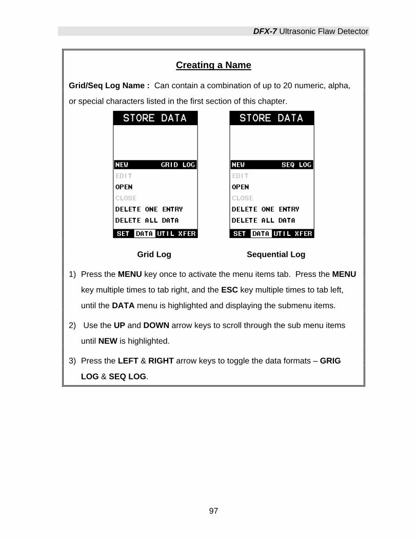
DFX-7 Ultrasonic Flaw Detector
97
Creating a Name
Grid/Seq Log Name : Can contain a combination of up to 20 numeric, alpha,
or special characters listed in the first section of this chapter.
Grid Log Sequential Log
1) Press the MENU key once to activate the menu items tab. Press the MENU
key multiple times to tab right, and the ESC key multiple times to tab left,
until the DATA menu is highlighted and displaying the submenu items.
2) Use the UP and DOWN arrow keys to scroll through the sub menu items
until NEW is highlighted.
3) Press the LEFT & RIGHT arrow keys to toggle the data formats – GRIG
LOG & SEQ LOG.
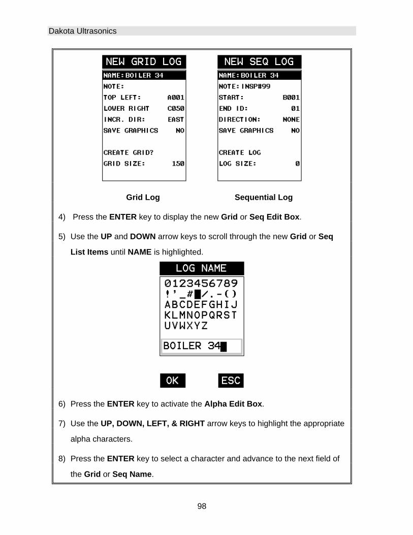
Dakota Ultrasonics
98
Grid Log Sequential Log
4) Press the ENTER key to display the new Grid or Seq Edit Box.
5) Use the UP and DOWN arrow keys to scroll through the new Grid or Seq
List Items until NAME is highlighted.
6) Press the ENTER key to activate the Alpha Edit Box.
7) Use the UP, DOWN, LEFT, & RIGHT arrow keys to highlight the appropriate
alpha characters.
8) Press the ENTER key to select a character and advance to the next field of
the Grid or Seq Name.
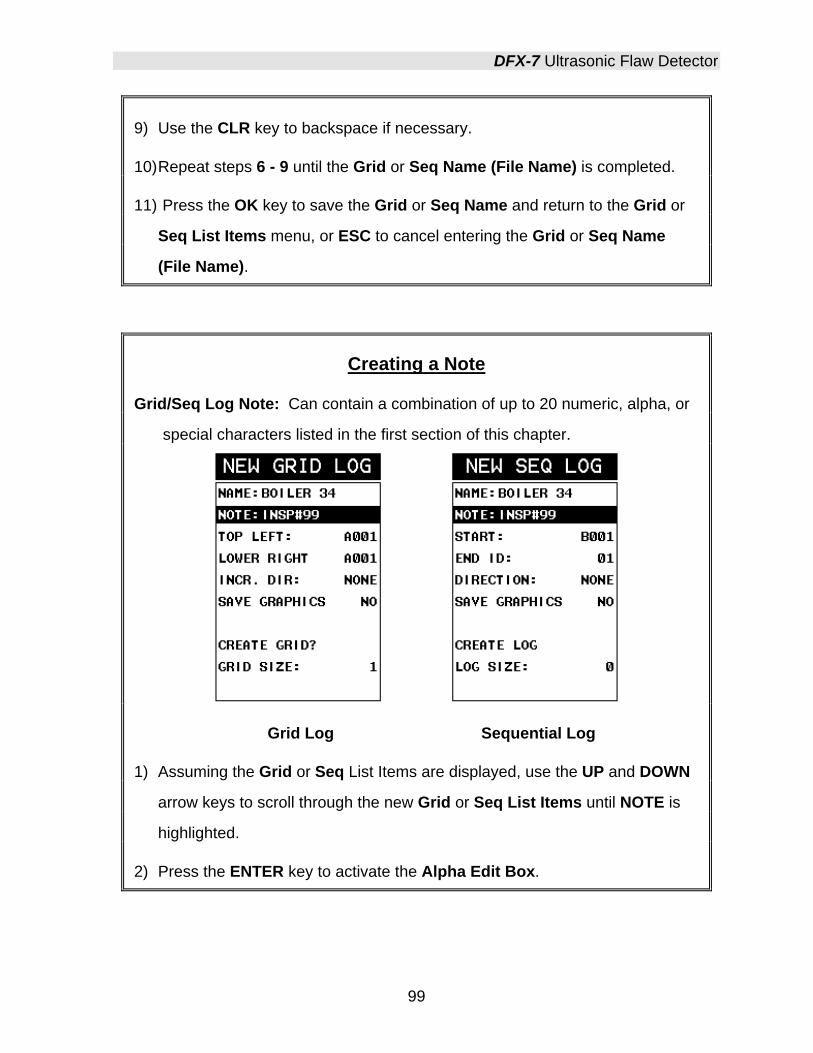
DFX-7 Ultrasonic Flaw Detector
99
9) Use the CLR key to backspace if necessary.
10) Repeat steps 6 - 9 until the Grid or Seq Name (File Name) is completed.
11) Press the OK key to save the Grid or Seq Name and return to the Grid or
Seq List Items menu, or ESC to cancel entering the Grid or Seq Name
(File Name).
Creating a Note
Grid/Seq Log Note: Can contain a combination of up to 20 numeric, alpha, or
special characters listed in the first section of this chapter.
Grid Log Sequential Log
1) Assuming the Grid or Seq List Items are displayed, use the UP and DOWN
arrow keys to scroll through the new Grid or Seq List Items until NOTE is
highlighted.
2) Press the ENTER key to activate the Alpha Edit Box.
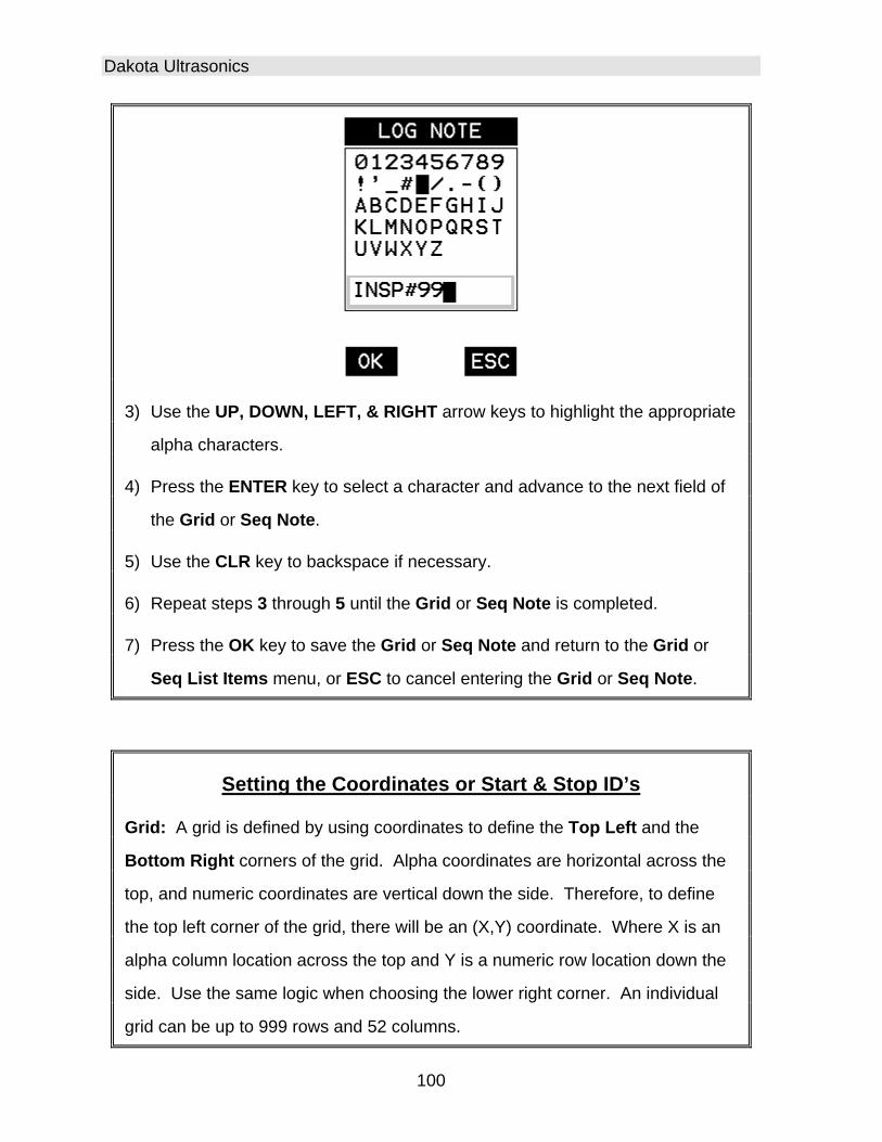
Dakota Ultrasonics
100
3) Use the UP, DOWN, LEFT, & RIGHT arrow keys to highlight the appropriate
alpha characters.
4) Press the ENTER key to select a character and advance to the next field of
the Grid or Seq Note.
5) Use the CLR key to backspace if necessary.
6) Repeat steps 3 through 5 until the Grid or Seq Note is completed.
7) Press the OK key to save the Grid or Seq Note and return to the Grid or
Seq List Items menu, or ESC to cancel entering the Grid or Seq Note.
Setting the Coordinates or Start & Stop ID’s
Grid: A grid is defined by using coordinates to define the Top Left and the
Bottom Right corners of the grid. Alpha coordinates are horizontal across the
top, and numeric coordinates are vertical down the side. Therefore, to define
the top left corner of the grid, there will be an (X,Y) coordinate. Where X is an
alpha column location across the top and Y is a numeric row location down the
side. Use the same logic when choosing the lower right corner. An individual
grid can be up to 999 rows and 52 columns.

DFX-7 Ultrasonic Flaw Detector
101
Sequential: The sequential file format can be viewed as a file as a single
column of up to 512 possible rows (readings), and a column of corresponding
identifiers associated with each individual reading. The identifier can be a
combination of up to 10 numeric, alpha, or special characters listed above,
while the file name can consist of a combination of up to 20 of the same
character set. Note: The identifier cannot start or end with a special character.
Once a start and end ID are entered into the DFX-7 and the log created, the
DFX-7 will automatically generate all the identifiers within that range.
Setting the Top Left(Grid) or Start ID(Seq)
Grid Log Sequential Log
1) Use the UP and DOWN arrow keys to scroll through the new Grid or Seq
List Items until TOP LEFT or START ID is highlighted.
2) Press the ENTER key to activate the Coordinate or Start ID Edit Box.
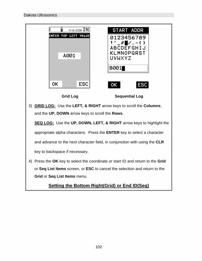
Dakota Ultrasonics
102
Grid Log Sequential Log
3) GRID LOG: Use the LEFT, & RIGHT arrow keys to scroll the Columns,
and the UP, DOWN arrow keys to scroll the Rows.
SEQ LOG: Use the UP, DOWN, LEFT, & RIGHT arrow keys to highlight the
appropriate alpha characters. Press the ENTER key to select a character
and advance to the next character field, in conjunction with using the CLR
key to backspace if necessary.
4) Press the OK key to select the coordinate or start ID and return to the Grid
or Seq List Items screen, or ESC to cancel the selection and return to the
Grid or Seq List Items menu.
Setting the Bottom Right(Grid) or End ID(Seq)
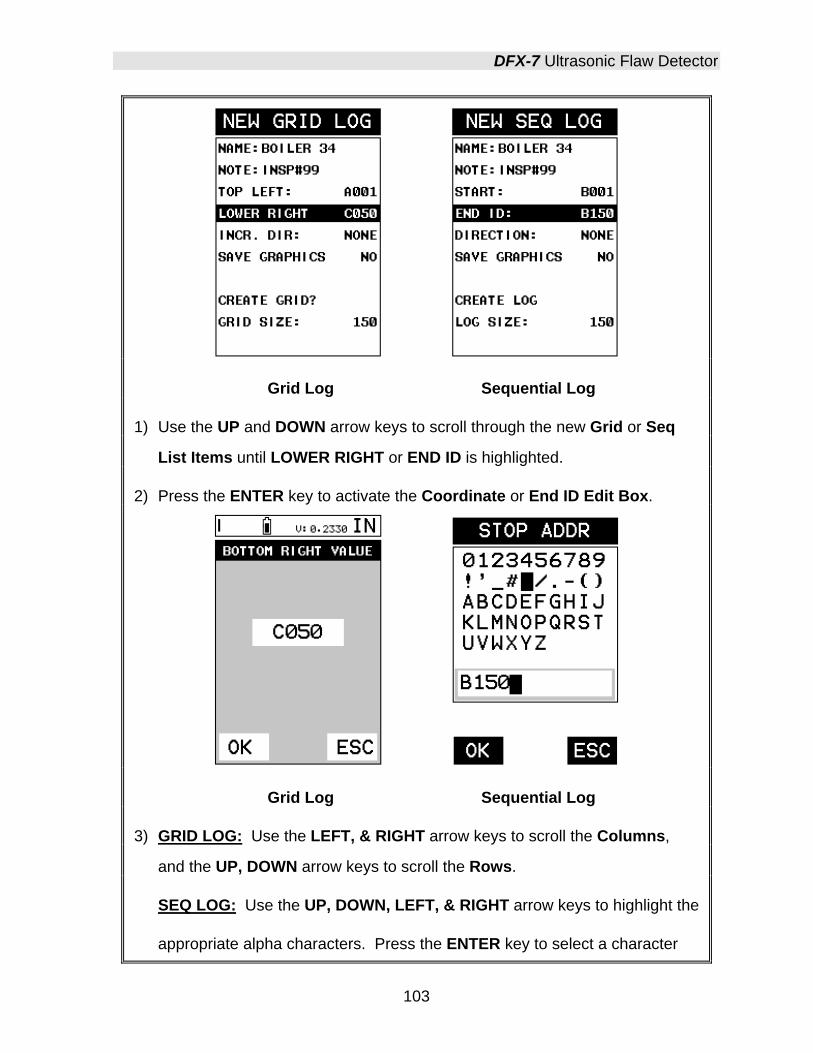
DFX-7 Ultrasonic Flaw Detector
103
Grid Log Sequential Log
1) Use the UP and DOWN arrow keys to scroll through the new Grid or Seq
List Items until LOWER RIGHT or END ID is highlighted.
2) Press the ENTER key to activate the Coordinate or End ID Edit Box.
Grid Log Sequential Log
3) GRID LOG: Use the LEFT, & RIGHT arrow keys to scroll the Columns,
and the UP, DOWN arrow keys to scroll the Rows.
SEQ LOG: Use the UP, DOWN, LEFT, & RIGHT arrow keys to highlight the
appropriate alpha characters. Press the ENTER key to select a character
Dakota Ultrasonics
104
and advance to the next character field, in conjunction with using the CLR
key to backspace if necessary.
4) Press the OK key to select the coordinate or end ID and return to the Grid
or Seq List Items screen, or ESC to cancel the selection and return to the
Grid or Seq List Items menu.
Note: If there is not enough memory available to create the grid or sequential
log, an error message box “NOT ENOUGH MEMORY“ will be displayed. Press
the OK or ESC key to return to the Grid or Seq List Items menu. It may be
necessary to free some memory in the DFX-7 at this time. Refer to page 111
for more information on Deleting a File.
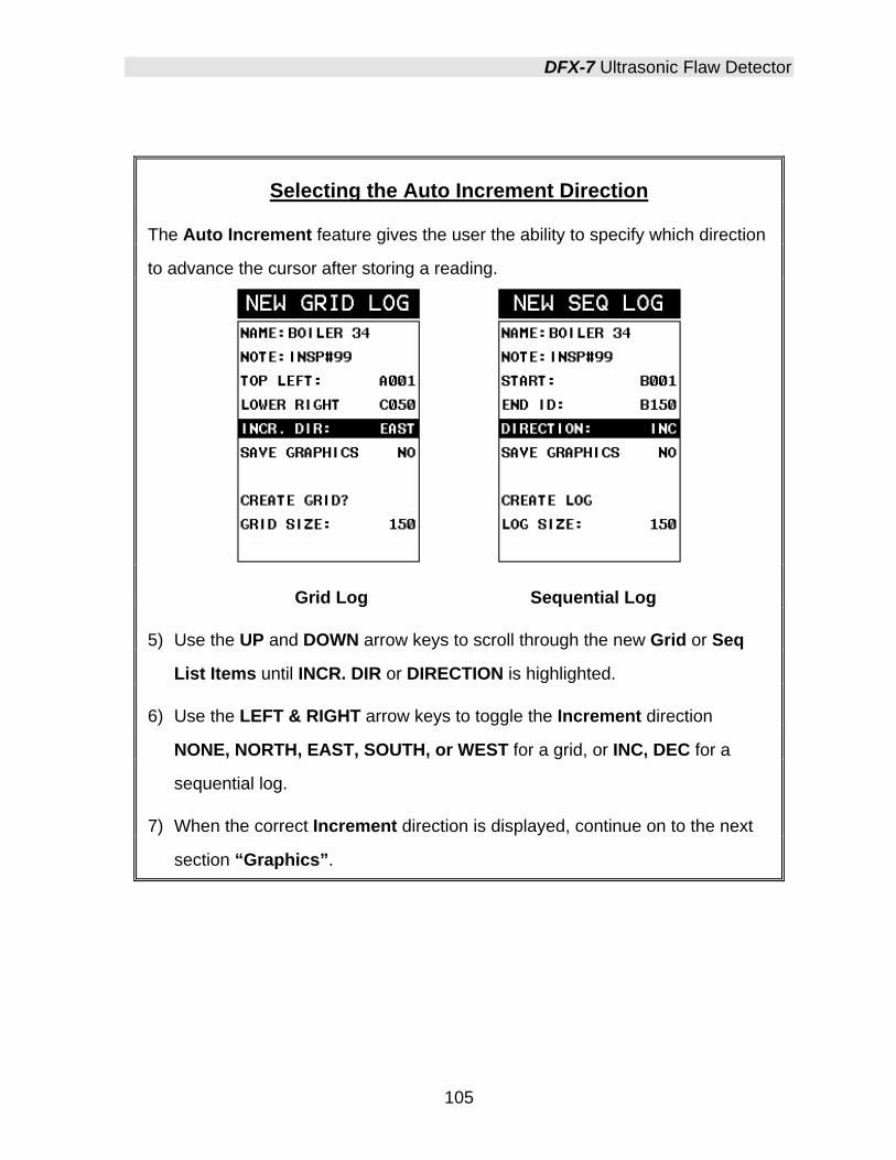
DFX-7 Ultrasonic Flaw Detector
105
Selecting the Auto Increment Direction
The Auto Increment feature gives the user the ability to specify which direction
to advance the cursor after storing a reading.
Grid Log Sequential Log
5) Use the UP and DOWN arrow keys to scroll through the new Grid or Seq
List Items until INCR. DIR or DIRECTION is highlighted.
6) Use the LEFT & RIGHT arrow keys to toggle the Increment direction
NONE, NORTH, EAST, SOUTH, or WEST for a grid, or INC, DEC for a
sequential log.
7) When the correct Increment direction is displayed, continue on to the next
section “Graphics”.
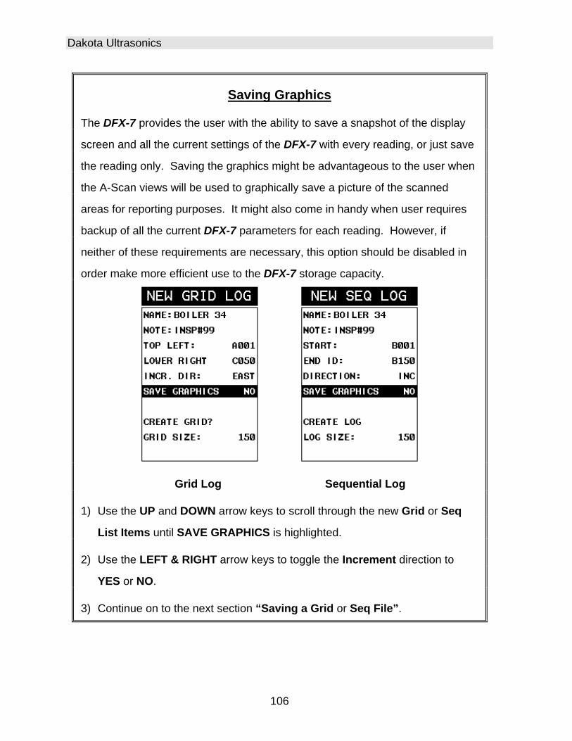
Dakota Ultrasonics
106
Saving Graphics
The DFX-7 provides the user with the ability to save a snapshot of the display
screen and all the current settings of the DFX-7 with every reading, or just save
the reading only. Saving the graphics might be advantageous to the user when
the A-Scan views will be used to graphically save a picture of the scanned
areas for reporting purposes. It might also come in handy when user requires
backup of all the current DFX-7 parameters for each reading. However, if
neither of these requirements are necessary, this option should be disabled in
order make more efficient use to the DFX-7 storage capacity.
Grid Log Sequential Log
1) Use the UP and DOWN arrow keys to scroll through the new Grid or Seq
List Items until SAVE GRAPHICS is highlighted.
2) Use the LEFT & RIGHT arrow keys to toggle the Increment direction to
YES or NO.
3) Continue on to the next section “Saving a Grid or Seq File”.
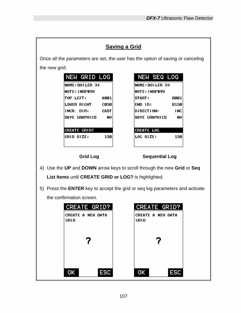
DFX-7 Ultrasonic Flaw Detector
107
Saving a Grid
Once all the parameters are set, the user has the option of saving or canceling
the new grid.
Grid Log Sequential Log
4) Use the UP and DOWN arrow keys to scroll through the new Grid or Seq
List Items until CREATE GRID or LOG? is highlighted.
5) Press the ENTER key to accept the grid or seq log parameters and activate
the confirmation screen.
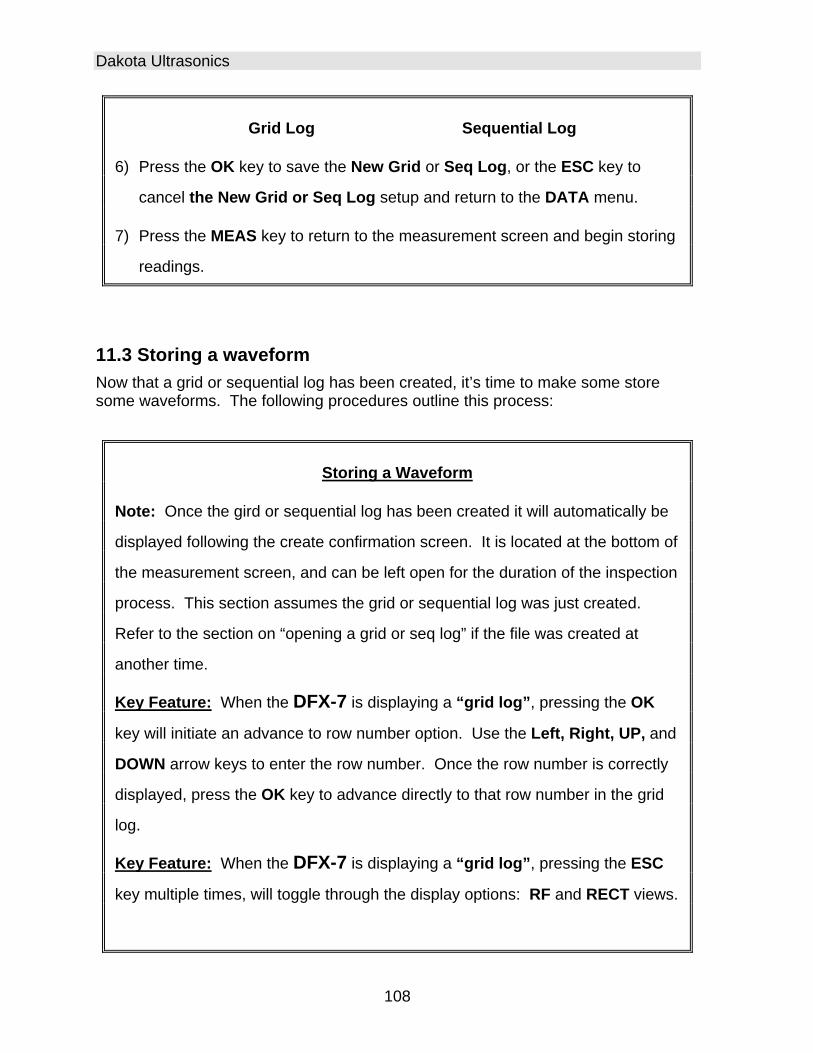
Dakota Ultrasonics
108
Grid Log Sequential Log
6) Press the OK key to save the New Grid or Seq Log, or the ESC key to
cancel the New Grid or Seq Log setup and return to the DATA menu.
7) Press the MEAS key to return to the measurement screen and begin storing
readings.
11.3 Storing a waveform Now that a grid or sequential log has been created, it’s time to make some store some waveforms. The following procedures outline this process:
Storing a Waveform
Note: Once the gird or sequential log has been created it will automatically be
displayed following the create confirmation screen. It is located at the bottom of
the measurement screen, and can be left open for the duration of the inspection
process. This section assumes the grid or sequential log was just created.
Refer to the section on “opening a grid or seq log” if the file was created at
another time.
Key Feature: When the DFX-7 is displaying a “grid log”, pressing the OK
key will initiate an advance to row number option. Use the Left, Right, UP, and
DOWN arrow keys to enter the row number. Once the row number is correctly
displayed, press the OK key to advance directly to that row number in the grid
log.
Key Feature: When the DFX-7 is displaying a “grid log”, pressing the ESC
key multiple times, will toggle through the display options: RF and RECT views.
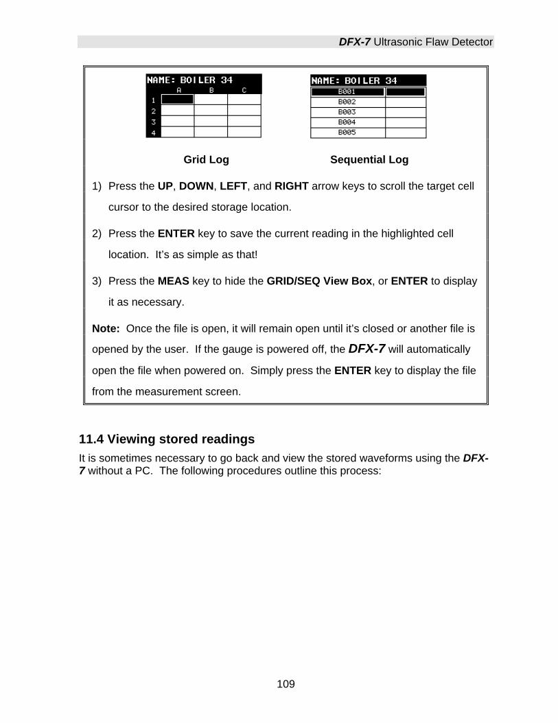
DFX-7 Ultrasonic Flaw Detector
109
Grid Log Sequential Log
1) Press the UP, DOWN, LEFT, and RIGHT arrow keys to scroll the target cell
cursor to the desired storage location.
2) Press the ENTER key to save the current reading in the highlighted cell
location. It’s as simple as that!
3) Press the MEAS key to hide the GRID/SEQ View Box, or ENTER to display
it as necessary.
Note: Once the file is open, it will remain open until it’s closed or another file is
opened by the user. If the gauge is powered off, the DFX-7 will automatically
open the file when powered on. Simply press the ENTER key to display the file
from the measurement screen.
11.4 Viewing stored readings It is sometimes necessary to go back and view the stored waveforms using the DFX-7 without a PC. The following procedures outline this process:
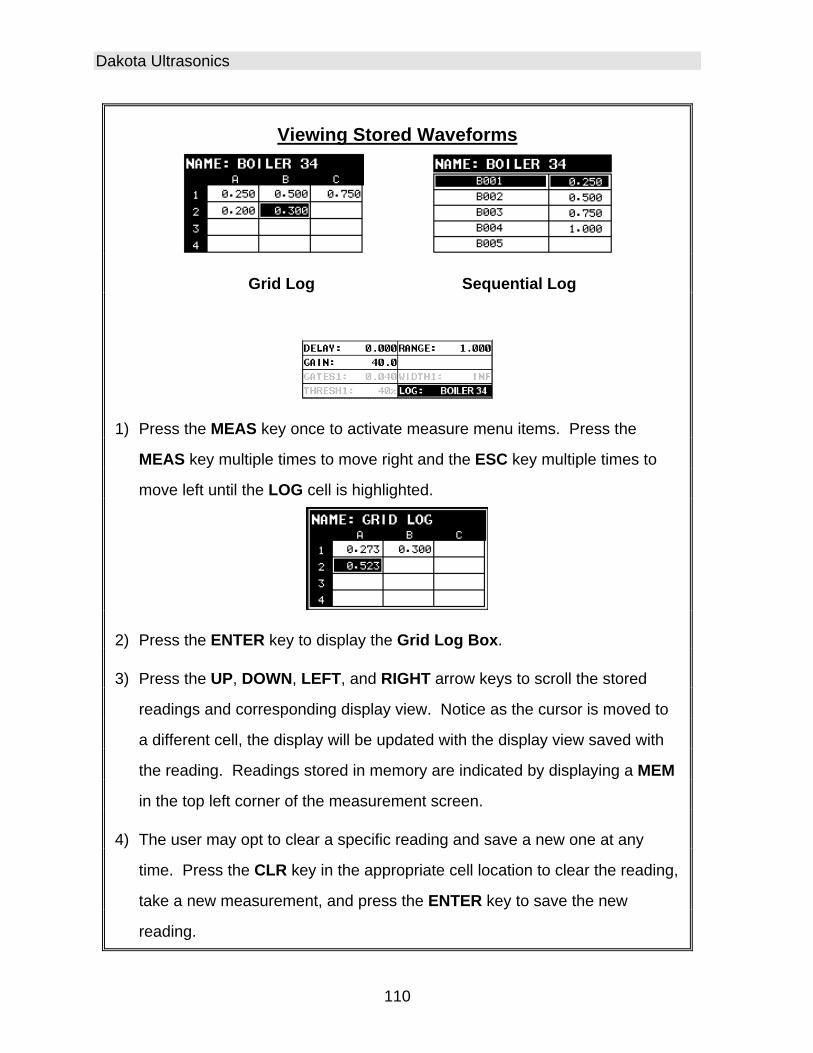
Dakota Ultrasonics
110
Viewing Stored Waveforms
Grid Log Sequential Log
1) Press the MEAS key once to activate measure menu items. Press the
MEAS key multiple times to move right and the ESC key multiple times to
move left until the LOG cell is highlighted.
2) Press the ENTER key to display the Grid Log Box.
3) Press the UP, DOWN, LEFT, and RIGHT arrow keys to scroll the stored
readings and corresponding display view. Notice as the cursor is moved to
a different cell, the display will be updated with the display view saved with
the reading. Readings stored in memory are indicated by displaying a MEM
in the top left corner of the measurement screen.
4) The user may opt to clear a specific reading and save a new one at any
time. Press the CLR key in the appropriate cell location to clear the reading,
take a new measurement, and press the ENTER key to save the new
reading.
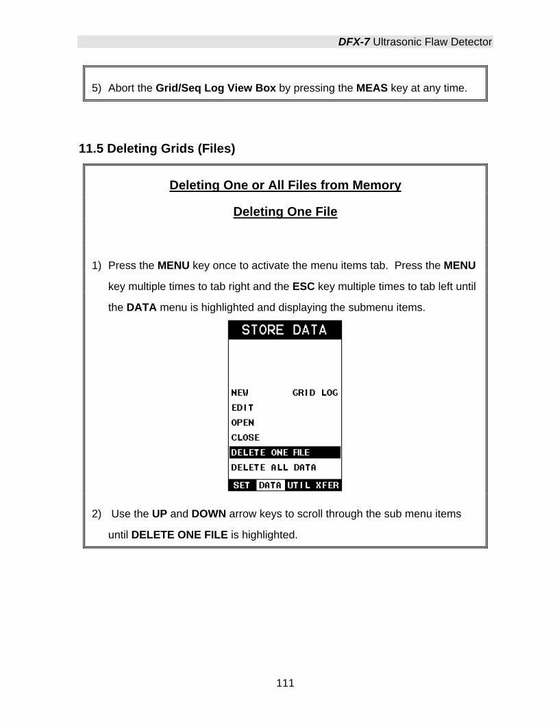
DFX-7 Ultrasonic Flaw Detector
111
5) Abort the Grid/Seq Log View Box by pressing the MEAS key at any time.
11.5 Deleting Grids (Files)
Deleting One or All Files from Memory
Deleting One File
1) Press the MENU key once to activate the menu items tab. Press the MENU
key multiple times to tab right and the ESC key multiple times to tab left until
the DATA menu is highlighted and displaying the submenu items.
2) Use the UP and DOWN arrow keys to scroll through the sub menu items
until DELETE ONE FILE is highlighted.
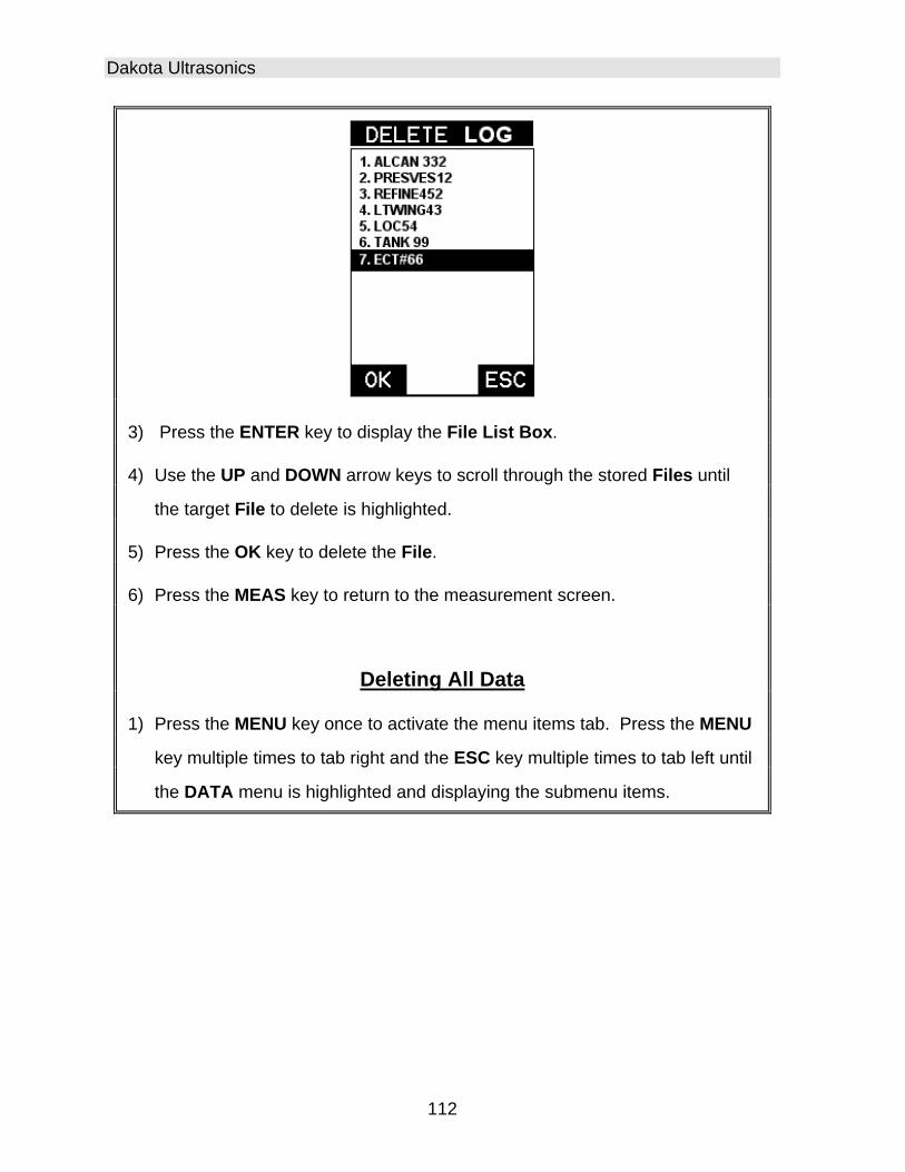
Dakota Ultrasonics
112
3) Press the ENTER key to display the File List Box.
4) Use the UP and DOWN arrow keys to scroll through the stored Files until
the target File to delete is highlighted.
5) Press the OK key to delete the File.
6) Press the MEAS key to return to the measurement screen.
Deleting All Data
1) Press the MENU key once to activate the menu items tab. Press the MENU
key multiple times to tab right and the ESC key multiple times to tab left until
the DATA menu is highlighted and displaying the submenu items.
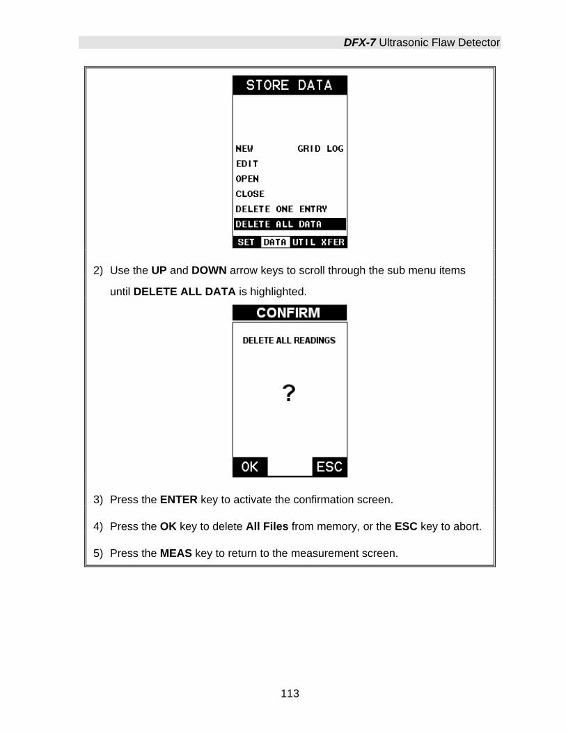
DFX-7 Ultrasonic Flaw Detector
113
2) Use the UP and DOWN arrow keys to scroll through the sub menu items
until DELETE ALL DATA is highlighted.
3) Press the ENTER key to activate the confirmation screen.
4) Press the OK key to delete All Files from memory, or the ESC key to abort.
5) Press the MEAS key to return to the measurement screen.
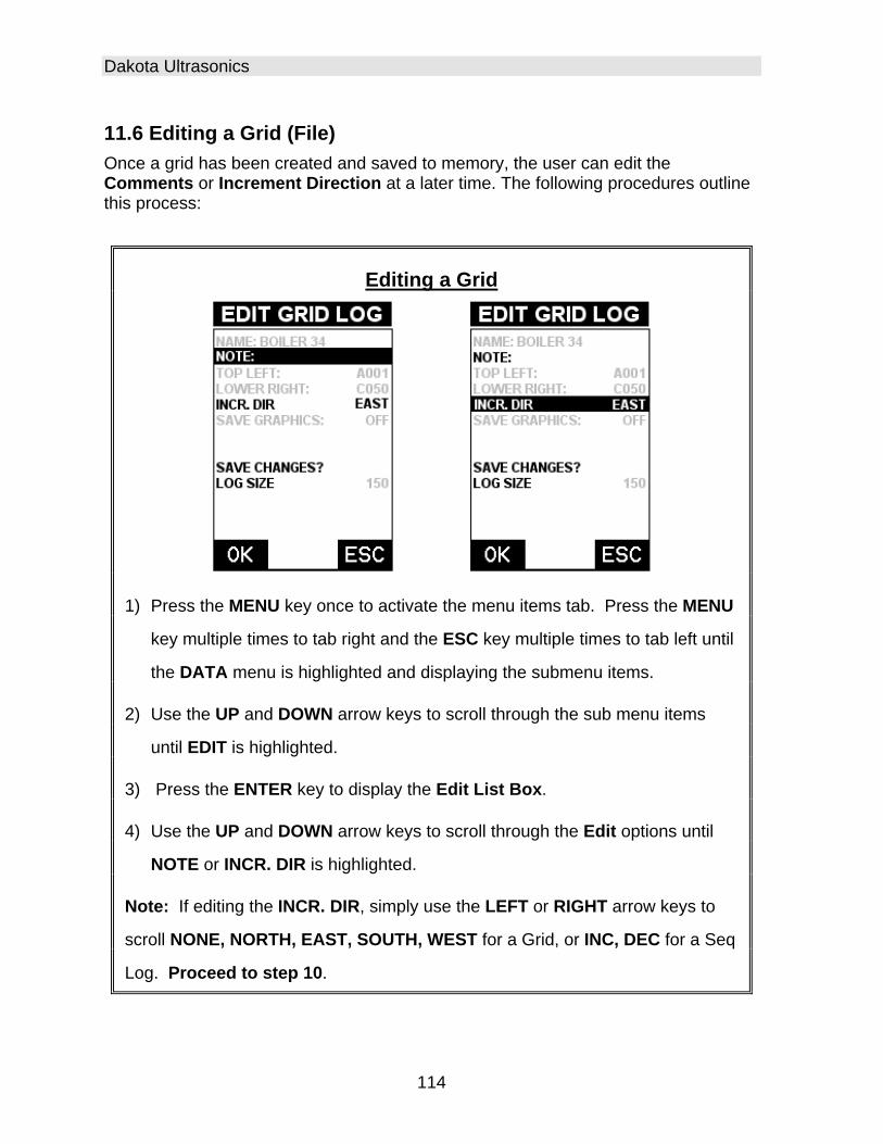
Dakota Ultrasonics
114
11.6 Editing a Grid (File) Once a grid has been created and saved to memory, the user can edit the Comments or Increment Direction at a later time. The following procedures outline this process:
Editing a Grid
1) Press the MENU key once to activate the menu items tab. Press the MENU
key multiple times to tab right and the ESC key multiple times to tab left until
the DATA menu is highlighted and displaying the submenu items.
2) Use the UP and DOWN arrow keys to scroll through the sub menu items
until EDIT is highlighted.
3) Press the ENTER key to display the Edit List Box.
4) Use the UP and DOWN arrow keys to scroll through the Edit options until
NOTE or INCR. DIR is highlighted.
Note: If editing the INCR. DIR, simply use the LEFT or RIGHT arrow keys to
scroll NONE, NORTH, EAST, SOUTH, WEST for a Grid, or INC, DEC for a Seq
Log. Proceed to step 10.
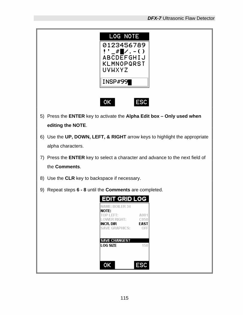
DFX-7 Ultrasonic Flaw Detector
115
5) Press the ENTER key to activate the Alpha Edit box – Only used when
editing the NOTE.
6) Use the UP, DOWN, LEFT, & RIGHT arrow keys to highlight the appropriate
alpha characters.
7) Press the ENTER key to select a character and advance to the next field of
the Comments.
8) Use the CLR key to backspace if necessary.
9) Repeat steps 6 - 8 until the Comments are completed.
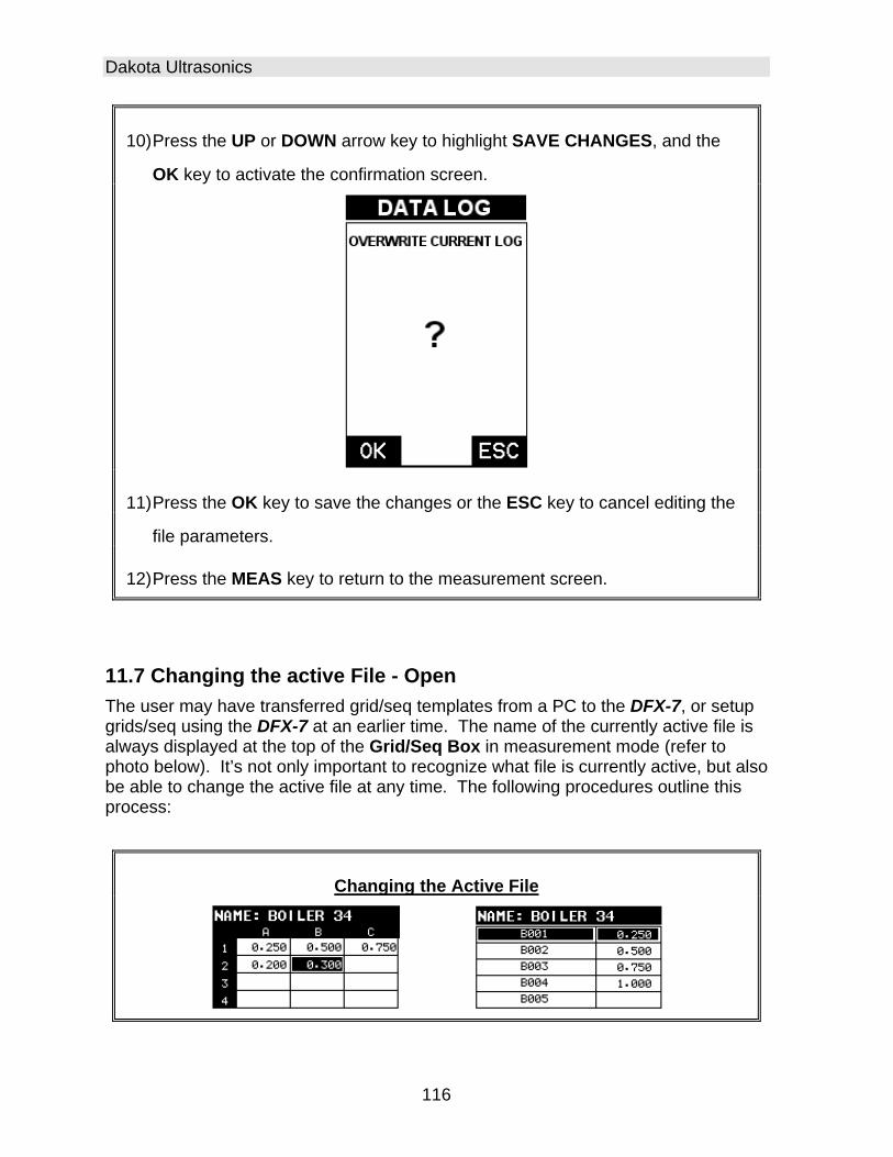
Dakota Ultrasonics
116
10) Press the UP or DOWN arrow key to highlight SAVE CHANGES, and the
OK key to activate the confirmation screen.
11) Press the OK key to save the changes or the ESC key to cancel editing the
file parameters.
12) Press the MEAS key to return to the measurement screen.
11.7 Changing the active File - Open The user may have transferred grid/seq templates from a PC to the DFX-7, or setup grids/seq using the DFX-7 at an earlier time. The name of the currently active file is always displayed at the top of the Grid/Seq Box in measurement mode (refer to photo below). It’s not only important to recognize what file is currently active, but also be able to change the active file at any time. The following procedures outline this process:
Changing the Active File
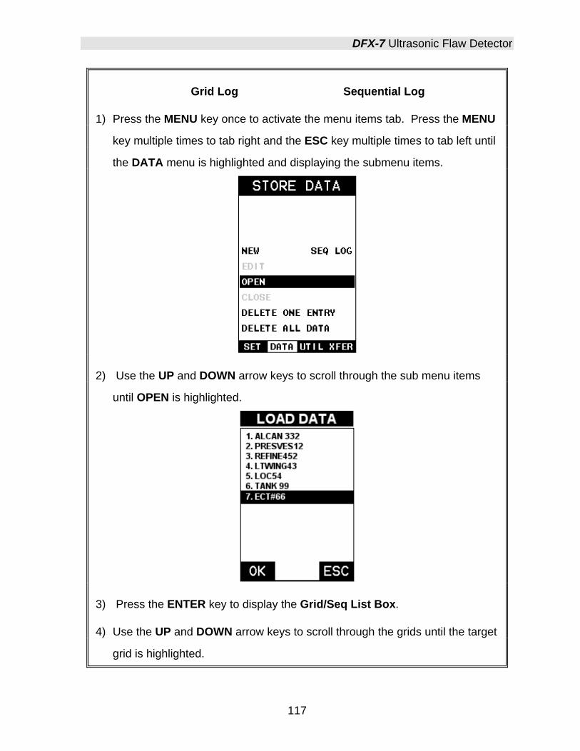
DFX-7 Ultrasonic Flaw Detector
117
Grid Log Sequential Log
1) Press the MENU key once to activate the menu items tab. Press the MENU
key multiple times to tab right and the ESC key multiple times to tab left until
the DATA menu is highlighted and displaying the submenu items.
2) Use the UP and DOWN arrow keys to scroll through the sub menu items
until OPEN is highlighted.
3) Press the ENTER key to display the Grid/Seq List Box.
4) Use the UP and DOWN arrow keys to scroll through the grids until the target
grid is highlighted.
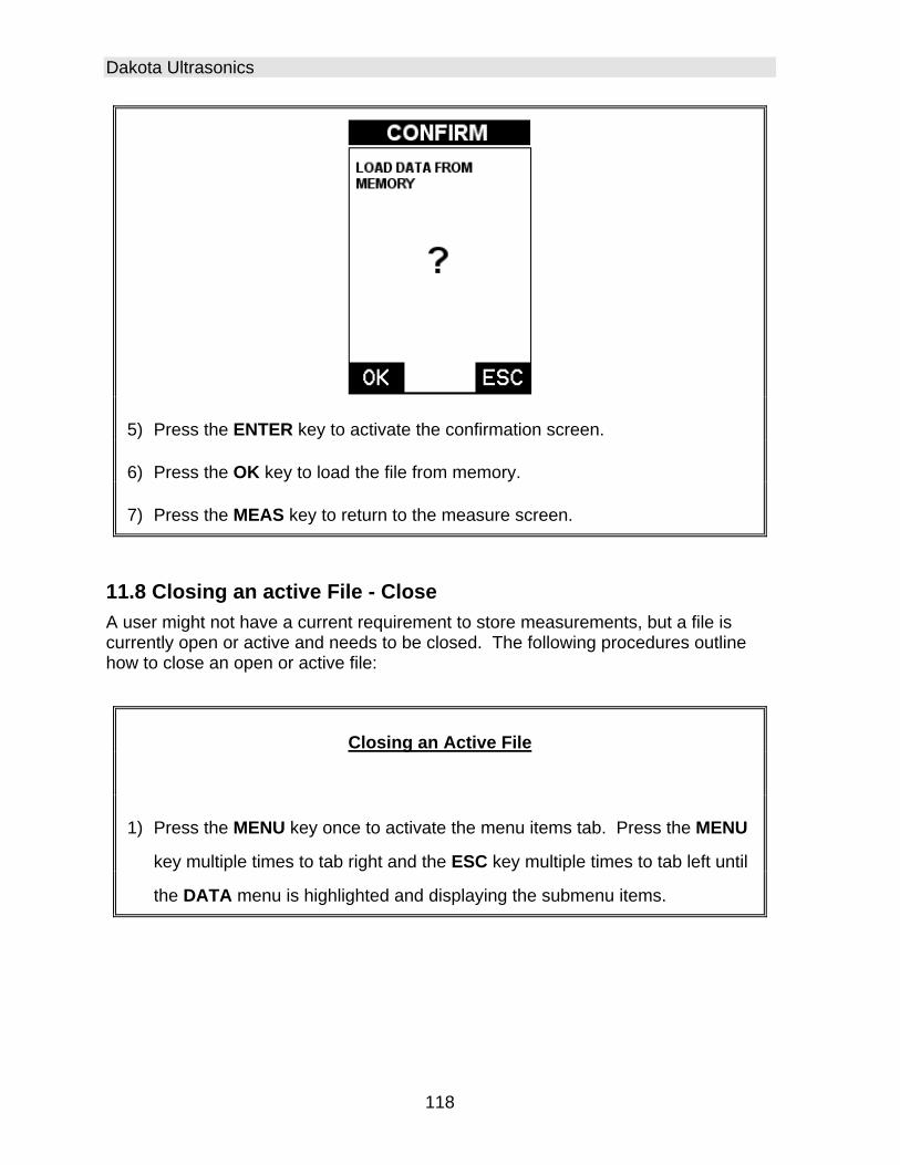
Dakota Ultrasonics
118
5) Press the ENTER key to activate the confirmation screen.
6) Press the OK key to load the file from memory.
7) Press the MEAS key to return to the measure screen.
11.8 Closing an active File - Close A user might not have a current requirement to store measurements, but a file is currently open or active and needs to be closed. The following procedures outline how to close an open or active file:
Closing an Active File
1) Press the MENU key once to activate the menu items tab. Press the MENU
key multiple times to tab right and the ESC key multiple times to tab left until
the DATA menu is highlighted and displaying the submenu items.
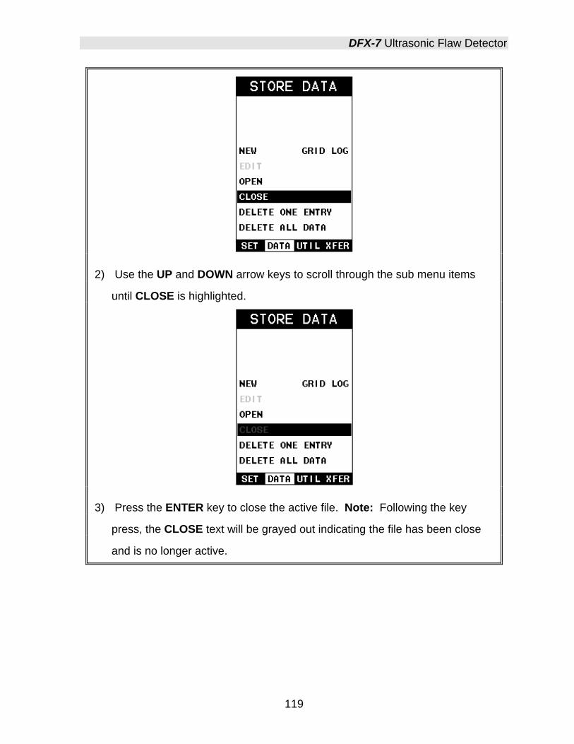
DFX-7 Ultrasonic Flaw Detector
119
2) Use the UP and DOWN arrow keys to scroll through the sub menu items
until CLOSE is highlighted.
3) Press the ENTER key to close the active file. Note: Following the key
press, the CLOSE text will be grayed out indicating the file has been close
and is no longer active.
120
CHAPTER TWELVE SETUPS – CREATE, STORE, EDIT, & RECALL
12.1 Introduction to Setups Often times, users are faced with a variety of tasks and applications that are sometimes similar, but can also be very different. Without the ability to save the individual calibrations and setups, the user would have to repeat the setup process on a regular basis for each individual application. This would become tedious rather quickly, especially considering the number of applications and potential calibration requirements for setup. The increased number of features and parameters also adds to the overall setup time, or amount of time to set up marginal applications with perfection and understanding. Because of the additional time involved, the DFX-7 has been equipped with the ability to save these setups to memory and be recalled at any time. The DFX-7 can store up to 64 custom setups. These setups can be bi-directionally transferred to and from a PC. Therefore, the user can save as many setups as necessary for all their individual applications requirements. This saves a great deal of time and knowledge for future inspections of the same job or project. This feature also eliminates error between two or more users during the setup and calibration process.
12.2 Opening a Setup The DFX-7 is loaded with a number of setups from the factory. These setups can be opened, edited, and saved to any one of 64 setup locations. If a factory setup is written over, the user can simply reload the default factory setups at anytime using the utility software included with the DFX-7. The factory setups are general setups Only. However, they may serve as an excellent starting point, requiring only minor adjustments to work for custom applications. It is recommended that user customized setups be saved to an empty location, and save the factory setups for the purpose of a general starting point. The following procedures outline how to open factory and custom setups:
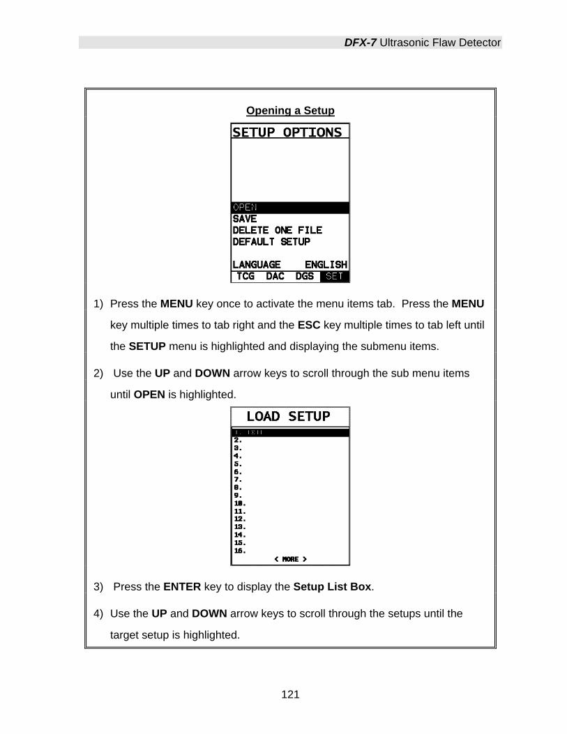
DFX-7 Ultrasonic Flaw Detector
121
Opening a Setup
1) Press the MENU key once to activate the menu items tab. Press the MENU
key multiple times to tab right and the ESC key multiple times to tab left until
the SETUP menu is highlighted and displaying the submenu items.
2) Use the UP and DOWN arrow keys to scroll through the sub menu items
until OPEN is highlighted.
3) Press the ENTER key to display the Setup List Box.
4) Use the UP and DOWN arrow keys to scroll through the setups until the
target setup is highlighted.
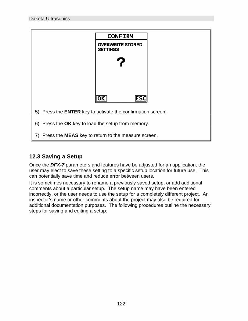
Dakota Ultrasonics
122
5) Press the ENTER key to activate the confirmation screen.
6) Press the OK key to load the setup from memory.
7) Press the MEAS key to return to the measure screen.
12.3 Saving a Setup Once the DFX-7 parameters and features have be adjusted for an application, the user may elect to save these setting to a specific setup location for future use. This can potentially save time and reduce error between users. It is sometimes necessary to rename a previously saved setup, or add additional comments about a particular setup. The setup name may have been entered incorrectly, or the user needs to use the setup for a completely different project. An inspector’s name or other comments about the project may also be required for additional documentation purposes. The following procedures outline the necessary steps for saving and editing a setup:
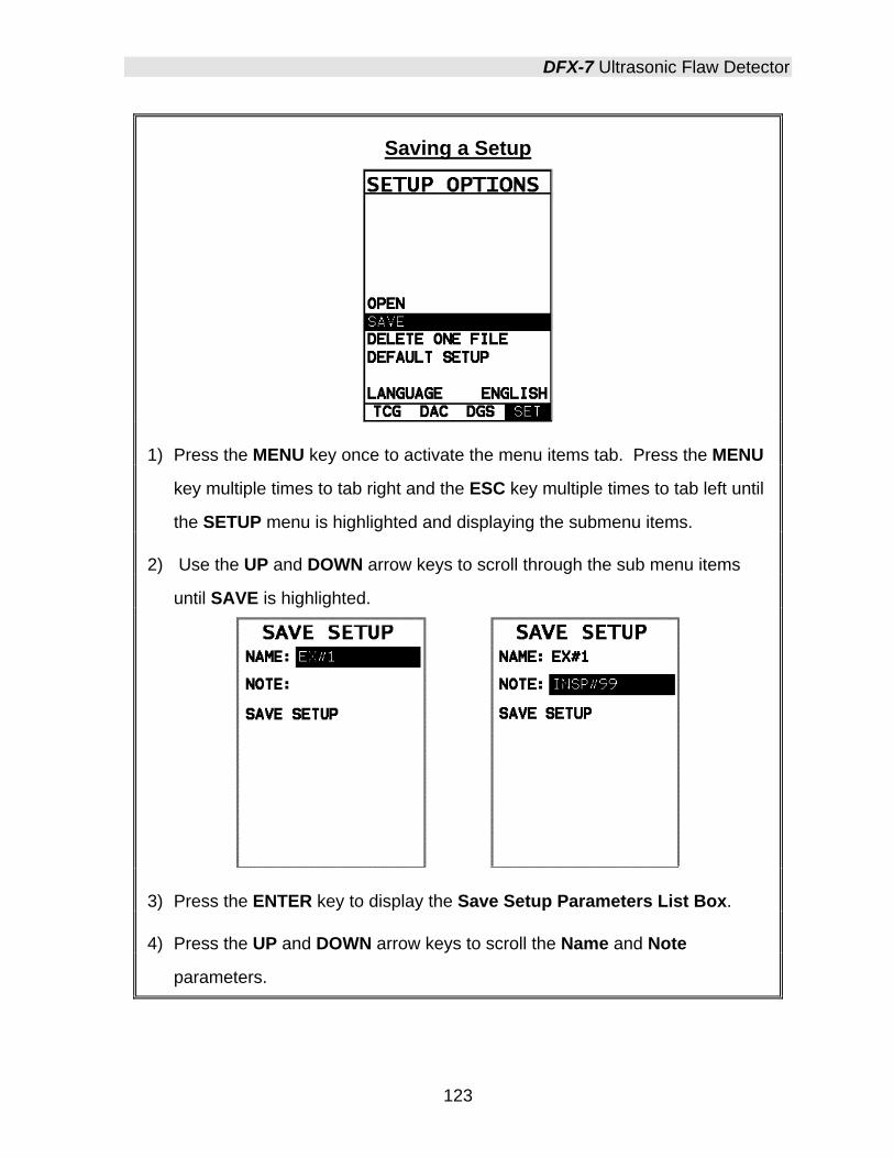
DFX-7 Ultrasonic Flaw Detector
123
Saving a Setup
1) Press the MENU key once to activate the menu items tab. Press the MENU
key multiple times to tab right and the ESC key multiple times to tab left until
the SETUP menu is highlighted and displaying the submenu items.
2) Use the UP and DOWN arrow keys to scroll through the sub menu items
until SAVE is highlighted.
3) Press the ENTER key to display the Save Setup Parameters List Box.
4) Press the UP and DOWN arrow keys to scroll the Name and Note
parameters.
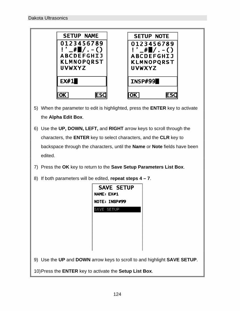
Dakota Ultrasonics
124
5) When the parameter to edit is highlighted, press the ENTER key to activate
the Alpha Edit Box.
6) Use the UP, DOWN, LEFT, and RIGHT arrow keys to scroll through the
characters, the ENTER key to select characters, and the CLR key to
backspace through the characters, until the Name or Note fields have been
edited.
7) Press the OK key to return to the Save Setup Parameters List Box.
8) If both parameters will be edited, repeat steps 4 – 7.
9) Use the UP and DOWN arrow keys to scroll to and highlight SAVE SETUP.
10) Press the ENTER key to activate the Setup List Box.
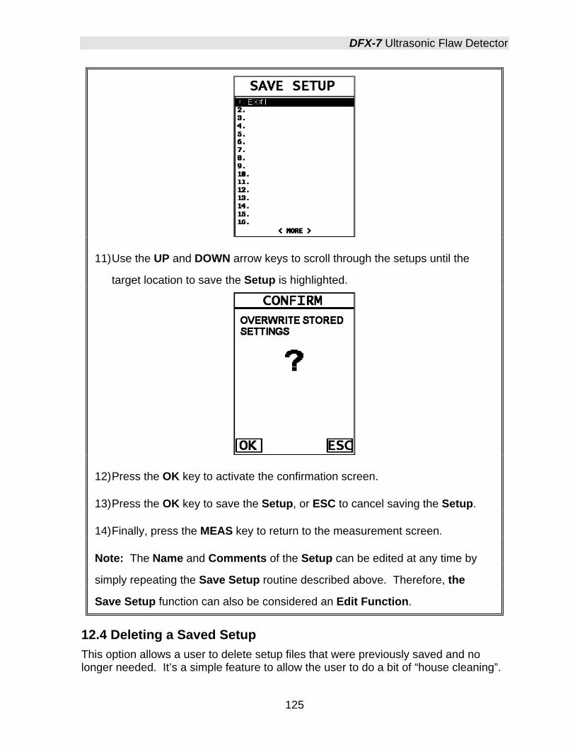
DFX-7 Ultrasonic Flaw Detector
125
11) Use the UP and DOWN arrow keys to scroll through the setups until the
target location to save the Setup is highlighted.
12) Press the OK key to activate the confirmation screen.
13) Press the OK key to save the Setup, or ESC to cancel saving the Setup.
14) Finally, press the MEAS key to return to the measurement screen.
Note: The Name and Comments of the Setup can be edited at any time by
simply repeating the Save Setup routine described above. Therefore, the
Save Setup function can also be considered an Edit Function.
12.4 Deleting a Saved Setup This option allows a user to delete setup files that were previously saved and no longer needed. It’s a simple feature to allow the user to do a bit of “house cleaning”.
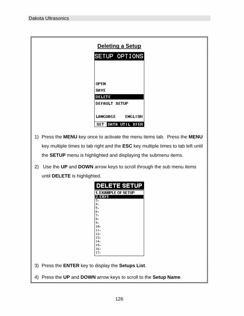
Dakota Ultrasonics
126
Deleting a Setup
1) Press the MENU key once to activate the menu items tab. Press the MENU
key multiple times to tab right and the ESC key multiple times to tab left until
the SETUP menu is highlighted and displaying the submenu items.
2) Use the UP and DOWN arrow keys to scroll through the sub menu items
until DELETE is highlighted.
3) Press the ENTER key to display the Setups List.
4) Press the UP and DOWN arrow keys to scroll to the Setup Name.
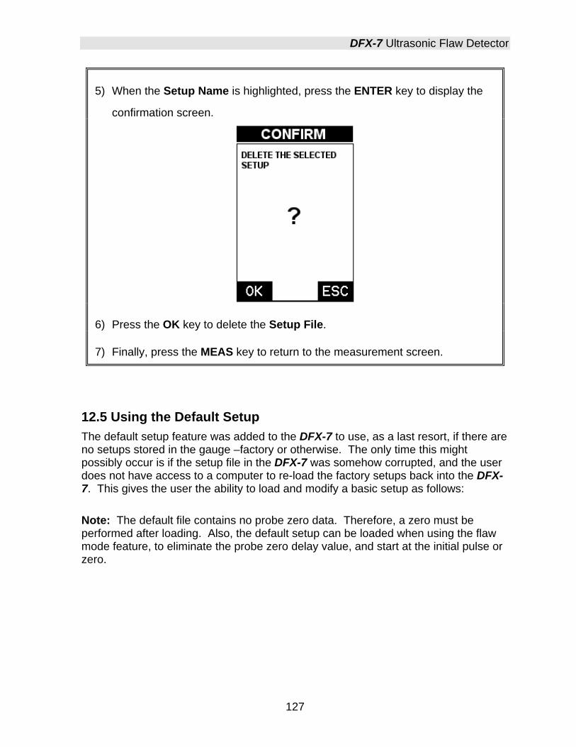
DFX-7 Ultrasonic Flaw Detector
127
5) When the Setup Name is highlighted, press the ENTER key to display the
confirmation screen.
6) Press the OK key to delete the Setup File.
7) Finally, press the MEAS key to return to the measurement screen.
12.5 Using the Default Setup The default setup feature was added to the DFX-7 to use, as a last resort, if there are no setups stored in the gauge –factory or otherwise. The only time this might possibly occur is if the setup file in the DFX-7 was somehow corrupted, and the user does not have access to a computer to re-load the factory setups back into the DFX-7. This gives the user the ability to load and modify a basic setup as follows: Note: The default file contains no probe zero data. Therefore, a zero must be performed after loading. Also, the default setup can be loaded when using the flaw mode feature, to eliminate the probe zero delay value, and start at the initial pulse or zero.

Dakota Ultrasonics
128
Using the Default Setup
1) Press the MENU key once to activate the menu items tab. Press the MENU
key multiple times to tab right and the ESC key multiple times to tab left until
the SETUP menu is highlighted and displaying the submenu items.
2) Use the UP and DOWN arrow keys to scroll through the sub menu items
until DEFAULT SETUP is highlighted.
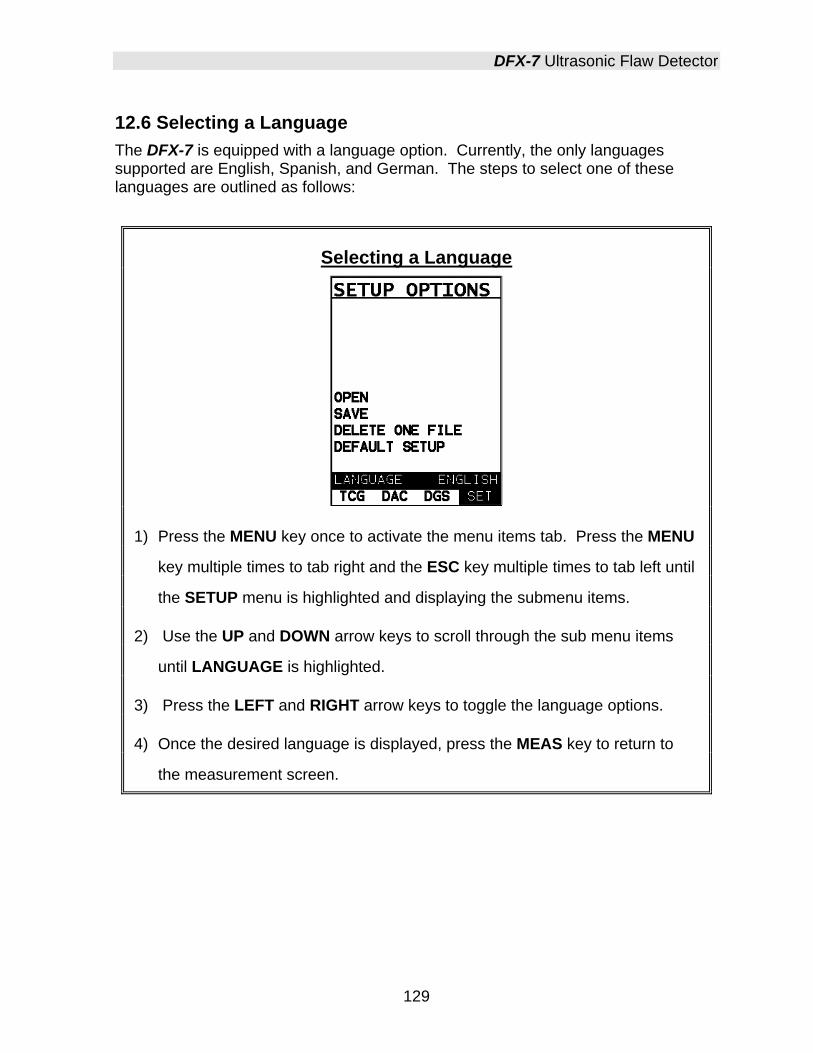
DFX-7 Ultrasonic Flaw Detector
129
12.6 Selecting a Language The DFX-7 is equipped with a language option. Currently, the only languages supported are English, Spanish, and German. The steps to select one of these languages are outlined as follows:
Selecting a Language
1) Press the MENU key once to activate the menu items tab. Press the MENU
key multiple times to tab right and the ESC key multiple times to tab left until
the SETUP menu is highlighted and displaying the submenu items.
2) Use the UP and DOWN arrow keys to scroll through the sub menu items
until LANGUAGE is highlighted.
3) Press the LEFT and RIGHT arrow keys to toggle the language options.
4) Once the desired language is displayed, press the MEAS key to return to
the measurement screen.
130
CHAPTER THIRTEEN USING THE UTILITY SOFTWARE
13.1 Computer System Requirements DakView will run on many different operating systems: Windows XP, Windows 2000 Professional, Windows 2000 Server, Windows 2000, Vista, or Windows 7 Advanced Server operating systems running on Intel or AMD hardware. A Pentium 166MHz or faster processor with at least 32 megabytes of physical RAM is required. You should have 40 megabytes of free disk space before attempting to install DakView. DakView requires an available communications port in order to transfer data to and from the DFX-7. DakView supports COM1, COM2, COM3, and COM4.
USB to Serial Converter Some newer laptop computers do not have standard serial ports. In this case it is possible to use a USB to Serial converter. If a serial to USB cable is needed, Contact Dakota Ultrasonics (pt# N-402-0510).
13.2 Installing DakView DakView comes on a CD-ROM with an automatic installer program. Place the CD in your computer’s CD tray and close the door. Open the CD-ROM by double clicking on the My Computer ICON, then double click on the CD. Finally, double click on the SETUP icon to begin the installation. Refer to the help section in DakView software for the complete operating manual, setup, and operation.
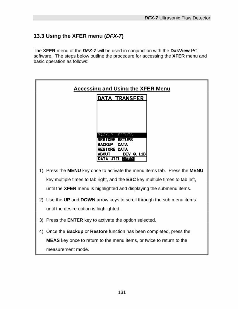
DFX-7 Ultrasonic Flaw Detector
131
13.3 Using the XFER menu (DFX-7) The XFER menu of the DFX-7 will be used in conjunction with the DakView PC software. The steps below outline the procedure for accessing the XFER menu and basic operation as follows:
Accessing and Using the XFER Menu
1) Press the MENU key once to activate the menu items tab. Press the MENU
key multiple times to tab right, and the ESC key multiple times to tab left,
until the XFER menu is highlighted and displaying the submenu items.
2) Use the UP and DOWN arrow keys to scroll through the sub menu items
until the desire option is highlighted.
3) Press the ENTER key to activate the option selected.
4) Once the Backup or Restore function has been completed, press the
MEAS key once to return to the menu items, or twice to return to the
measurement mode.
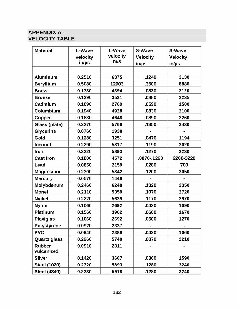
132
APPENDIX A - VELOCITY TABLE
Material L-Wave velocity
in/µs
L-Wave velocity
m/s
S-Wave Velocity in/µs
S-Wave Velocity in/µs
Aluminum 0.2510 6375 .1240 3130 Beryllium 0.5080 12903 .3500 8880 Brass 0.1730 4394 .0830 2120 Bronze 0.1390 3531 .0880 2235 Cadmium 0.1090 2769 .0590 1500 Columbium 0.1940 4928 .0830 2100 Copper 0.1830 4648 .0890 2260 Glass (plate) 0.2270 5766 .1350 3430 Glycerine 0.0760 1930 - - Gold 0.1280 3251 .0470 1194 Inconel 0.2290 5817 .1190 3020 Iron 0.2320 5893 .1270 3230 Cast Iron 0.1800 4572 .0870-.1260 2200-3220 Lead 0.0850 2159 .0280 700 Magnesium 0.2300 5842 .1200 3050 Mercury 0.0570 1448 - - Molybdenum 0.2460 6248 .1320 3350 Monel 0.2110 5359 .1070 2720 Nickel 0.2220 5639 .1170 2970 Nylon 0.1060 2692 .0430 1090 Platinum 0.1560 3962 .0660 1670 Plexiglas 0.1060 2692 .0500 1270 Polystyrene 0.0920 2337 - - PVC 0.0940 2388 .0420 1060 Quartz glass 0.2260 5740 .0870 2210 Rubber vulcanized
0.0910 2311 - -
Silver 0.1420 3607 .0360 1590 Steel (1020) 0.2320 5893 .1280 3240 Steel (4340) 0.2330 5918 .1280 3240
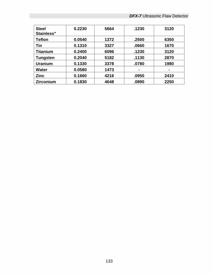
DFX-7 Ultrasonic Flaw Detector
133
Steel Stainless"
0.2230 5664 .1230 3120
Teflon 0.0540 1372 .2500 6350 Tin 0.1310 3327 .0660 1670 Titanium 0.2400 6096 .1230 3120 Tungsten 0.2040 5182 .1130 2870 Uranium 0.1330 3378 .0780 1980 Water 0.0580 1473 - - Zinc 0.1660 4216 .0950 2410 Zirconium 0.1830 4648 .0890 2250
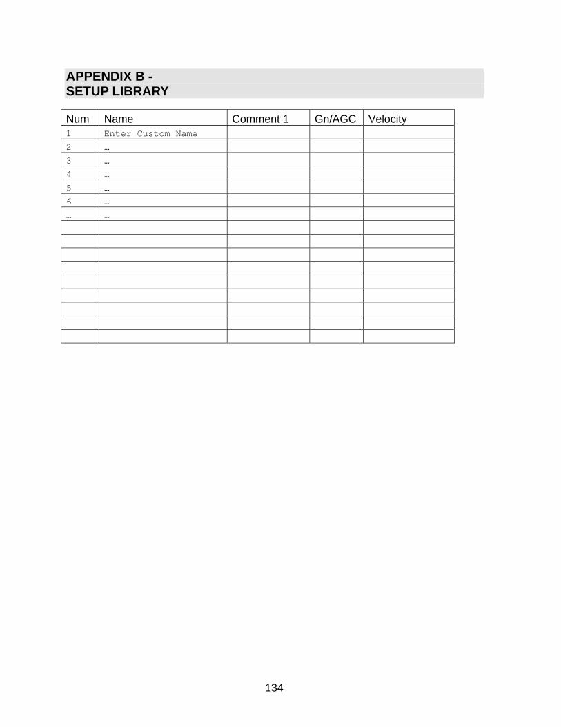
134
APPENDIX B - SETUP LIBRARY
Num Name Comment 1 Gn/AGC Velocity 1 Enter Custom Name
2 …
3 …
4 …
5 …
6 …
… …
135
WARRANTY INFORMATION
• Warranty Statement •
Dakota Ultrasonics warrants the DFX-7 against defects in materials and workmanship for a period of two years from receipt by the end user. Additionally, Dakota Ultrasonics warrants transducers and accessories against such defects for a period of 90 days from receipt by the end user. If Dakota Ultrasonics receives notice of such defects during the warranty period, Dakota Ultrasonics will either, at its option, repair or replace products that prove to be defective.
Should Dakota Ultrasonics be unable to repair or replace the product within a reasonable amount of time, the customer's alternative exclusive remedy shall be refund of the purchase price upon return of the product.
• Exclusions •
The above warranty shall not apply to defects resulting from: improper or inadequate maintenance by the customer; unauthorized modification or misuse; or operation outside the environmental specifications for the product.
Dakota Ultrasonics makes no other warranty, either express or implied, with respect to this product. Dakota Ultrasonics specifically disclaims any implied warranties of merchantability or fitness for a particular purpose. Some states or provinces do not allow limitations on the duration of an implied warranty, so the above limitation or exclusion may not apply to you. However, any implied warranty of merchantability or fitness is limited to the five-year duration of this written warranty.
This warranty gives you specific legal rights, and you may also have other rights which may vary from state to state or province to province.
• Obtaining Service During Warranty Period •
If your hardware should fail during the warranty period, contact Dakota Ultrasonics and arrange for servicing of the product. Retain proof of purchase in order to obtain warranty service.
For products that require servicing, Dakota Ultrasonics may use one of the following methods:
- Repair the product - Replace the product with a re-manufactured unit - Replace the product with a product of equal or greater performance - Refund the purchase price.
• After the Warranty Period •
If your hardware should fail after the warranty period, contact Dakota Ultrasonics for details of the services available, and to arrange for non-warranty service.


