! WARNING: Extended valve pulsing MAY reduce the life of your valves. Thank you for purchasing the revolutionary SwitchSpeed™ Controller by AccuAir. This air suspension controller manages up to 4 Air Springs as an intelligent switchbox with user-adjustable control of valve speed. The AccuAir SwitchSpeed™ also manages your Air Compressor(s) to keep onboard air at an ideal pressure for your application (If Optional Electronic Tank Pressure Sensor is connected). To maximize functionality, the AccuAir SwitchSpeed™ allows you to select from three distinct valve speeds: 1.) Full Speed. 2.) Medium Speed (Adjustable). 3.) Precision Speed (Adjustable). The exact settings for each of these speeds is User Adjustable (see page 10 in your Operation Manual). At AccuAir, we pride ourselves on thorough customer service, quality products, and a better driving experience through technologically superior design. Please visit our website or call us toll free to let us know if there is any way that we can help improve your AccuAir experience. (877) AIR-DOWN 247-3 6 9 6 Operation Manual SwitchSpeed™ Controller: Congratulations!
Transcript
! WARNING: Extended valve pulsing MAY reduce the life of your valves.
Thank you for purchasing the revolutionary SwitchSpeed™ Controller by AccuAir.
This air suspension controller manages up to 4 Air Springs as an intelligent switchbox with user-adjustable control of valve speed. The AccuAir SwitchSpeed™ also manages your Air Compressor(s) to keep onboard air at an ideal pressure for your application (If Optional Electronic Tank Pressure Sensor is connected).
To maximize functionality, the AccuAir SwitchSpeed™ allows you to select from three distinct valve speeds: 1.) Full Speed. 2.) Medium Speed (Adjustable). 3.) Precision Speed (Adjustable). The exact settings for each of these speeds is User Adjustable (see page 10 in your Operation Manual).
At AccuAir, we pride ourselves on thorough customer service, quality products, and a better driving experience through technologically superior design. Please visit our website or call us toll free to let us know if there is any way that we can help improve your AccuAir experience.
Terms & Conditions:AccuAir Control Systems, L.L.C. is hereby referred to as ACCUAIR. The Pur-chaser, end-user, or installer is hereby referred to as CUSTOMER.
WarrantyACCUAIR will repair or replace any failed components for the life of the vehicle given that the components were installed and operated as intended by ACCUAIR. Upon the return of a failed component(s), ACCUAIR will determine the cause of failure. If it is due to improper installation, or misuse of the system, a repair charge will be assessed and the customer will be contacted before work is performed or replacement parts are shipped. If the failure is due to faulty parts, then ACCUAIR will repair or replace the failed components at their own discretion and in a timely manner.
Repairs and ReturnsA Return Merchandise Authorization Number (RMA) is required for ALL ship-ments to AccuAir Control Systems. This number should be written in large letters on the shipping box. Call AccuAir to receive an RMA number and send items to:
AccuAir Control Systems, L.L.C.Attn: Service Department/RMA # ______
1241 Johnson Ave. #355San Luis Obispo, Ca, 93401
USA
Legal Disclaimer•ACCUAIR’s products must be installed by a qualified professional installation facility as recommended by ACCUAIR.
•System operation and installation is at the CUSTOMER’s own risk. ACCUAIR accepts no liability for damage of property or persons caused by its products, components, accessories, installation instructions or otherwise.
•ACCUAIR accepts no responsibility for systems, products or components provided by other manufacturers for use with or around the ACCUAIR system. For components other than ACCUAIR’s, follow the manufacturer’s instructions for installation and operation.
! WARNING: No part of the vehicle should be able to contact the ground when all air is out of the air springs.
For simplicity of use and understanding we refer to the four wheels of a vehicle by number. Instead of using “Left Front”, or “Right Front” etc. Refer to the following diagram for labeling:
FRONT 2
43
1
! CAUTION: For all under vehicle maintenance, you must first disable the air system by removing the main system fuse located near the battery.
While parked, you may choose to automatically lower all four Air Springs to zero height. The system will adjust at the currently Selected Speed. There are two modes for this function: (See page 11 for selecting Mode Type.)
TIMER:Press the All-Down “ ” Button for 3 seconds.
The All-Down “ ” Indicator Light will flash while lowering the vehicle and turn off based on a timer.
MOMENTARY:Press the All-Down “ ” Button until the vehicle is as low as you desire.
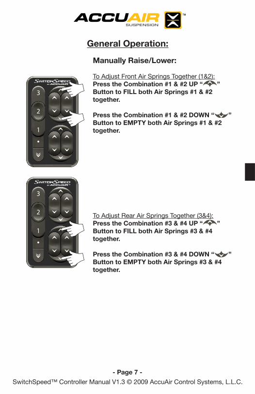
General Operation:
! NOTE: This sequence can be stopped immediately by pressing any of the Arrow Buttons on the right side of the controller.
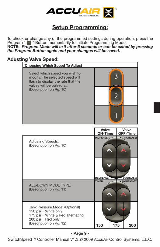
Select which speed you wish to modify. The selected speed will flash to display the rate that the valves will be pulsed at. (Description on Pg. 10)
150 200175
ALL-DOWN MODE TYPE.(Description on Pg. 11)
Tank Pressure Mode: (Optional)150 psi = White only 175 psi = White & Red alternating 200 psi = Red only(Description on Pg. 12)
Adjusting Speeds: (Description on Pg. 10)
DECREASE:DECREASE:TIMER:
INCREASE:
ValveON-Time
INCREASE:
ValveOFF-Time
MOMENTARY:
To check or change any of the programmed settings during operation, press the Program “ ” Button momentarily to initiate Programming Mode: NOTE: Program Mode will exit after 5 seconds or can be exited by pressing the Program Button again and your changes will be saved.
Restoring the DEFAULT Pulse Time Settings:With the Ignition ON hold the Program “ ” Button & Speed #1 “ ” Button for 5 seconds until all of the Speed Indicators strobe up and down. This will Restore the SwitchSpeed™ to the DEFAULT Pulse ON / OFF Times.
Selecting ALL-DOWN Mode Type:
Change ALL-DOWN Mode To TIMER or MOMEMTARY:With the Ignition ON, press the Program “ ” Button. Next press the #3 UP “ ” Button to turn ALL-DOWN Mode to TIMER and the #4 UP “ ” Button to turn ALL-DOWN Mode toMOMENTARY.
When the #3 UP “ ” Arrow is White: ALL-DOWN Mode is TIMER.
When the #4 UP “ ” Arrow is Red: ALL-DOWN Mode is MOMENTARY.
NOTE: Program Mode will exit after 5 seconds or can be exited by pressing the Program Button again and your changes will be saved.
Tank Pressure Mode: (If Optional Electronic Tank Pressure Sensor is Connected)
Your system was shipped with the Tank Pressure Mode set at 150 PSI. If you have High Pressure Compressor(s) you can change the Tank Pressure Mode to 175 PSI or 200 PSI using the following Procedure:
To Change The Tank Pressure Mode:With the Ignition ON, press the Program “ ” Button. Next press the #3 DOWN “ ” Button to set Tank Pressure Mode to 150 PSI, the #4 DOWN “ ” Button once to set the Tank Pressure Mode to 175 PSI and the #4 DOWN “ ” Button again to set the Tank Pressure Mode to 200 PSI.
When the #3 DOWN “ ” Arrow is White: Tank Pressure Mode is at 150 PSI.
When the #3 DOWN “ ” Arrow and the #4 DOWN “ ” Arrow are alternating ON & OFF: Tank Pressure Mode is at 175 PSI.
When the #4 DOWN “ ” Arrow is Red: Tank Pressure Mode is at 200 PSI.
NOTE: If the Electronic Tank Pressure Sensor is NOT in use the #3 DOWN “ ” & #4 DOWN “ ” Arrows are OFF.
NOTE: Program Mode will exit after 5 seconds or can be exited by pressing the Program Button again and your changes will be saved.
Setup Programming:
200
175
150 Mode:• 110 psi ON / 150 psi OFF175 Mode: • 135 psi ON / 175 psi OFF 200 Mode: • 160 psi ON / 200 psi OFF
The SwitchSpeed™ Controller’s backlighting will turn on automatically when the system is on. The Backlighting will change to Nighttime Mode when the headlights are ON. The Brightness of both Modes can be adjusted with the procedure below: NOTE: With the headlights OFF you will be adjusting Daytime Mode with the following procedure. With the headlights ON you will be adjusting Nighttime Mode with the following procedure.
NOTE: The SwitchSpeed™ Backlighting brightness will adjust UP & DOWN as you change the settings.
To Adjust The Backlighing UP or DOWN:With the Ignition ON, press the Program “ ” Button. Next press the Combination #1 & #2 UP “ ” Button to make the Backlighting BRIGHTER.
With the Ignition ON, press the Program “ ” Button. Next press the Combination #1 & #2 DOWN “ ” Button to make the Backlighting DARKER.
NOTE: Program Mode will exit after 5 seconds or can be exited by pressing the Program Button again and your changes will be saved.
Preasure Sensor Warning Number Of Flashes between the 2 second pauseTank pressure is not increasing after the ECU turns the Compressor(s) ON.
• Verify Compressor circuit wiring connections.• Check Compressor fuse F2.• Verify Compressor plumbing connections.• Check for Compressor relay failure.• Check for Compressor failure.• Check for Pressure Sensor failure.
Pressure Sensor is not reading.
• Verify wiring to Pressure Sensor.• Check Pressure Sensor for failure.
2
4
In the unlikely case of a system component failure during operation, the Speed “ ”, “ ”, & “ ” Indications will flash simultaneously and sequentially to indicate the trouble codes outlined below.
NOTE: This is the ONLY time that all 3 of the Speed Selections will flash simultaneously during use.
If the vehicle system voltage drops below 10.5 volts during operation, the SwitchSpeed™ will automatically turn the compressor(s) OFF and show the trouble indication below. The SwitchSpeed™ will go back to normal operation once the vehicle system voltage reaches 12.5 volts or the ignition is cycled.
In the very unlikely case that the vehicle system voltage raises above 16.0 volts during operation, the SwitchSpeed™ will show the trouble indication below, but continue to operate like normal. Prolonged usage in this state may cause damage to system components.
Operation Trouble Indication/Diagnosis:
High Voltage WarningSystem Voltage is ABOVE 16.0V.
The Error Indication will flash
Sequentially UPWARD.
Warning Indication:Low Voltage WarningSystem Voltage is BELOW 10.5V.