OPERATION MANUAL PART 3 PLASTIC PROCESSING MACHINE Q8 /M10M Standard Edition:7TR_B11_1517_update Please read this manual carefully before the installation, operation and maintenance. Original instruction
Transcript
OPERATION MANUAL PART 3
PLASTIC PROCESSING MACHINE
Q8 / M10M Standard
Edition:7TR_B11_1517_update
Please read this manual carefully before the installation, operation and maintenance.
Original instruction
Pxa270 Standard Q8/M10M Version Manual
2
Preface
This Controller Manual for the Q8,M10M and M12M (Standard Version) .
Please refer to the Operations Manual for exact instructions on how to set up and program the machine‟s
clamping unit, injection unit, production monitor and the printing and networking functions.
Please note that the information in this manual is subject to change without notice.
We hope you will find this manual helpful for your machine operations. In order to help us improve our
products and documentation we encourage you to provide us with any feedback and suggestions for
improvement you might have.
This document remains our property and must not be copied without our written consent. Its contents may
neither be made known to third parties nor be used for non-approved purposes. This manual is for internal
use only.
Note: For avoid damage the operator or machine , produce the good quality products please read
careful the manual before running the machine.
Responsibility: The purchaser has the responsibility to ensure safety of operator and machine. The
people who is not be basic train and no knowledge of injection molding machine is not allow to operate the
machine.
Note:Not change the content of manual without approve.
Note:This manual is a general purpose, some page and function maybe not for your machine.
Note: This manual is only to the purchaser who will use the controller.
Pxa270 Standard Q8 Version Manual
3
Table of Contents Preface ................................................................................................................................ 2
1 Operations Manual The instructions within the Operations Manual assume that you are familiar with the HMI panel keys
and the various HMI display screens. If you are not or you are looking for more information on any
of the keys or display screens please refer to the appropriate section within the Reference Manual.
1.1 Clamping Unit Setup
When changing the mold follow the machine manufacturer‟s instructions at all times to avoid the
possibility of serious injuries to the machine operators.
After changing the mold you have to ensure that the mold and the nozzle/injection unit are properly
aligned to avoid damage to the machine. In addition, you need to make sure all necessary hose
connections to the mold have been properly established and the mold has been mounted securely.
1.1.1 Mould Height Adjustment
Before installing the mold use the Mold Adjustment keys to adjust for mold thickness and to advance
or retract core(s) if necessary.
Press the Reduced Mold Height Adjustment Key to roughly adjust for a reduced mold height
(reduced distance between moving and static platen) or the Increased Mold Height Adjustment Key
to roughly adjust for an increased mold height (increased distance between moving and static platen).
For continues platen movement press and hold the
key. The platen will move slightly and stop. Keep
the key pressed and after a one-second delay the
platen will start to move continuously. Release the
key to stop platen movement. If you press the key
and release it immediately, the platen will move
slightly and stop, allowing for micro adjustments.
You can repeat this operation until the moving
platen has reached the desired position.
Caution: Regarding to the safety issue, please stop
the motor from operating and turn OFF the
machine while installing the new mold.
Once you have finished the installation of the new
mold, close the safety gate, turn on the machine
and press the Manual Mold Height Adjustment On/Off Key once to activate the Manual Mold
Height Adjustment mode. Switch the HMI
display to the Other Settings screen by pressing
F9 (Fast) F2 (Adjm). This screen allows you to
change the speed and pressure settings after the
mold has been changed. If necessary, adjust the
pressure, speed and position settings for the new
mold or load the mold set data.
After adjusting the settings press the Manual Mold Height Adjustment On/Off key again to
close the mold. While closing the mold the
controller will execute an automatic mold height
adjustment until the new settings are reached.
Once the automatic adjustment has finished all
machine operations will stop and the alarm will
sound. This indicates that you can now switch
back to manual or automatic operation modes.
Warning: For the safety reasons, you have to switch the machine into Manual Operation mode by
pressing Manual key before you use the Mold Height Adjustment key or Manual key. If you wish to
use any other mode, please change to the Manual mode before switching to the mode you required.
Adjust the mold height.
Turn the machine off.
Install the new mold.
Turn the Machine on.
Switch to Manual Mold Height
Adjustment mode and, if necessary,
change the speed and pressure
settings or load the mold set data.
Execute the Automatic Mold Height
Adjustment.
Switch to normal operation mode.
Pxa270 Standard Q8 Version Manual
7
If you encounter any problems during the mold height adjustment press the Manual key for an
emergency reset to stop the operation.
1.1.2 Mold Closing and Mold Protection
Mold closing is executed in three phases: Close mold 1 stage, Close mold 2 stage, Close mold 3
stage, Low Pressure closing and High Pressure closing. For optimum productivity mold closing
should be executed as fast as possible. However, to avoid damage to the mold and/or machine it
is important to use correct settings to ensure appropriate mold protection. For this reason pay
particular attention to the Slow Speed phase.
Press the Manual key to activate the Manual mode. Switch the HMI display to the Clamp
Settings screen by pressing F2 (Clamp).
Set the Mold Opening Stroke. The Mold Opening
Stroke is measured from the closed mold.
Therefore the Mold Opening Stroke position is
“0” when the mold is in its closed position.
Next enter the desired hydraulic speed and
pressure settings for the three mold closing
phases. You have to ensure that the settings
allow for a smooth, jerk-free movement of the
mold.
Set the hydraulic speed for the Low Speed phase
low enough to avoid damage to the mold in case
a jammed part has remained in the mold. For the
same reason set the lowest hydraulic pressure
possible.
To avoid damage to the mold the transition point
for switching between High Speed and Low Speed phase should be set before the position
where the mold could come into possible contact
with a jammed part.
The transition point for switching from the Low
Speed to the High Pressure phase should be set
at the position where both parts of the mold are
starting to touch to initiate the high pressure
mold lock-up.
To accelerate mold closing you can activate the
differential high-speed mold closing option for
the High Speed closing phase.
After setting all mold closing parameters execute mold closing in Manual Mode to check for
optimum machine performance. If you encounter any problems during the mold closing adjustment
press the Manual key for an emergency reset to stop the operation.
Switch into Manual Mode.
Set the Mold Opening Stroke.
Set the hydraulic speed and pressure
for the three mold closing phases.
Set the transition position for
switching from the High Speed phase
to the Low Speed phase.
Set the transition position for
switching from the Low Speed phase
to the High Pressure phase.
Execute mold closing in Manual
Mode to verify the settings and to
check for optimum performance.
Pxa270 Standard Q8/M10M Version Manual
8
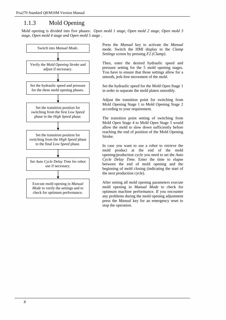
1.1.3 Mold Opening
Mold opening is divided into five phases: Open mold 1 stage, Open mold 2 stage, Open mold 3
stage, Open mold 4 stage and Open mold 5 stage .
Press the Manual key to activate the Manual mode. Switch the HMI display to the Clamp
Settings screen by pressing F2 (Clamp).
Then, enter the desired hydraulic speed and
pressure setting for the 5 mold opening stages.
You have to ensure that those settings allow for a
smooth, jerk-free movement of the mold.
Set the hydraulic speed for the Mold Open Stage 1
in order to separate the mold platen smoothly.
Adjust the transition point for switching from
Mold Opening Stage 1 to Mold Opening Stage 2
according to your requirement.
The transition point setting of switching from
Mold Open Stage 4 to Mold Open Stage 5 would
allow the mold to slow down sufficiently before
reaching the end of position of the Mold Opening
Stroke.
In case you want to use a robot to retrieve the
mold product at the end of the mold
opening/production cycle you need to set the Auto
Cycle Delay Time. Enter the time to elapse
between the end of mold opening and the
beginning of mold closing (indicating the start of
the next production cycle).
After setting all mold opening parameters execute
mold opening in Manual Mode to check for
optimum machine performance. If you encounter
any problems during the mold opening adjustment
press the Manual key for an emergency reset to
stop the operation.
Switch into Manual Mode.
Verify the Mold Opening Stroke and
adjust if necessary.
Set the transition position for
switching from the first Low Speed
phase to the High Speed phase.
Set the transition position for
switching from the High Speed phase
to the final Low Speed phase.
Execute mold opening in Manual
Mode to verify the settings and to
check for optimum performance.
Set Auto Cycle Delay Time for robot
use if necessary.
Set the hydraulic speed and pressure
for the three mold opening phases.
Pxa270 Standard Q8 Version Manual
9
1.1.4 Ejector
The ejector can be operated in three different modes to knock the finished product out of the mold at
the end of mold opening. You can choose between the Hold, Count Number and the Vibration modes.
The Hold mode is used during semi-automatic operation. The ejector moves forward according to
the ejector settings and the product is dropped or taken out. After the safety gate has been opened
and closed the next cycle will start.
In Count Number mode the ejector is activated according to the Ejector and Ejection Count settings.
This mode is usually used for automatic machine operation. It does not require the opening and
closing of the safety door to continue the production cycle.
If you use the Vibration mode the ejector movement is controlled by the Ejector and Ejection Count settings with the ejector vibrating at the end of the forward movement according to the Vibration
setting set in the Parameter 2 screen (setting No. 6) before retracting again.
Press the Manual key to activate the Manual mode. Switch the HMI display to the Ejection
Settings screen by pressing F5 (Eject).
First, set the Ejection Mode and Count. Please
note, if you want to deactivate the ejector you
can do so by setting the Ejection Count to “0”.
The Eject Try Again function is used for the
Photo Sensor auto operation mode. If the mold
product cannot be knocked out completely, the
alarm will sound and the ejector will be activated
again. If the mold product is then successfully
knocked out the machine will resume normal
operation; otherwise it will stop for trouble
shooting.
If the mold product has not been knocked out
successfully while in Photo Sensor auto
operation mode and the Eject Try Again function
is not activated, the alarm will sound and the
machine will stop for ejection trouble shooting.
The initial ejection is divided into two phases
that can be controlled separately. Set the pressure,
speed and transition position individually for
each phase.
Then, please set the pressure and speed for the
ejection retract.The Backward Delay time allows
you to set the time the ejector will stay in the
forward end position before it is retracted. (But
will not maintain ejector forward, pressure,
speed and electromagnetic valve).
If you require additional cooling of the mold
product after mold opening, set the Ejector
Activation Delay Time accordingly.
After setting all ejection parameters activate the
ejector in Manual Mode to check for optimum
machine performance. If you encounter any
problems during the ejection set-up press
theManual key for an emergency reset to stop
the operation.
Set the Ejection Mode and Count.
Set the Forward Pressure and Speed
for both phases.
Set the Forward End Position and
Vibration time (if necessary).
Set the transition point for switching
between first and second phase.
Set the Backward pressure and
speed and delay time (if necessary).
Set the Backward end position.
Set the Ejector Activation Delay
Time if necessary.
Activate the ejector in Manual Mode
to verify the settings and to check for
optimum performance.
Switch into Manual Mode.
Pxa270 Standard Q8/M10M Version Manual
10
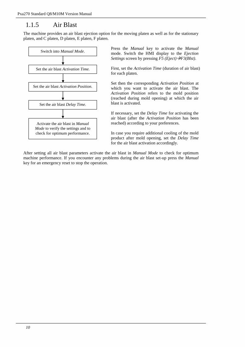
1.1.5 Air Blast
The machine provides an air blast ejection option for the moving platen as well as for the stationary
platen, and C platen, D platen, E platen, F platen.
Press the Manual key to activate the Manual mode. Switch the HMI display to the Ejection
Settings screen by pressing F5 (Eject)F3(Blst).
First, set the Activation Time (duration of air blast)
for each platen.
Set then the corresponding Activation Position at
which you want to activate the air blast. The
Activation Position refers to the mold position
(reached during mold opening) at which the air
blast is activated.
If necessary, set the Delay Time for activating the
air blast (after the Activation Position has been
reached) according to your preferences.
In case you require additional cooling of the mold
product after mold opening, set the Delay Time
for the air blast activation accordingly.
After setting all air blast parameters activate the air blast in Manual Mode to check for optimum
machine performance. If you encounter any problems during the air blast set-up press the Manual
key for an emergency reset to stop the operation.
Set the air blast Activation Time.
Switch into Manual Mode.
Set the air blast Delay Time.
Set the air blast Activation Position.
Activate the air blast in Manual
Mode to verify the settings and to
check for optimum performance.
Pxa270 Standard Q8 Version Manual
11
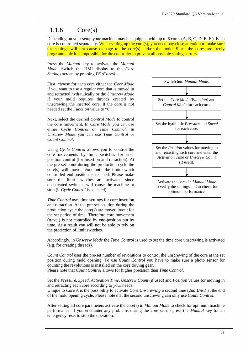
1.1.6 Core(s)
Depending on your setup your machine may be equipped with up to 6 cores (A, B, C, D, E, F ). Each
core is controlled separately. When setting up the core(s), you need pay close attention to make sure
the settings will not cause damage to the core(s) and/or the mold. Since the cores are freely
programmable it is impossible for the controller to prevent all possible settings errors.
Press the Manual key to activate the Manual
Mode. Switch the HMI display to the Core Settings screen by pressing F6 (Cores).
First, choose for each core either the Core Mode
if you want to use a regular core that is moved in
and retracted hydraulically or the Unscrew Mode
if your mold requires threads created by
unscrewing the inserted core. If the core is not
needed set the Function value to “0”.
Next, select the desired Control Mode to control
the core movement. In Core Mode you can use
either Cycle Control or Time Control. In
Unscrew Mode you can use Time Control or
Count Control.
Using Cycle Control allows you to control the
core movements by limit switches for end-
position control (for insertion and retraction). At
the pre-set point during the production cycle the
core(s) will move in/out until the limit switch
controlled end-position is reached. Please make
sure the limit switches are activated since
deactivated switches will cause the machine to
stop (if Cycle Control is selected).
Time Control uses time settings for core insertion
and retraction. At the pre-set position during the
production cycle the core(s) are moved in/out for
the set period of time. Therefore core movement
(travel) is not controlled by end-position but by
time. As a result you will not be able to rely on
the protection of limit switches.
Accordingly, in Unscrew Mode the Time Control is used to set the time core unscrewing is activated
(e.g. for creating threads).
Count Control uses the pre-set number of revolutions to control the unscrewing of the core at the set
position during mold opening. To use Count Control you have to make sure a photo sensor for
counting the revolutions is installed on the core driving gear.
Please note that Count Control allows for higher precision than Time Control.
Set the Pressure, Speed, Activation Time, Unscrew Count (if used) and Position values for moving in
and retracting each core according to your needs.
Unique to Core A is the possibility to activate Core Unscrewing a second time (2nd Uns.) at the end
of the mold opening cycle. Please note that the second unscrewing can only use Count Control.
After setting all core parameters activate the core(s) in Manual Mode to check for optimum machine
performance. If you encounter any problems during the core set-up press the Manual key for an
emergency reset to stop the operation.
Set the Core Mode (Function) and
Control Mode for each core.
Set the hydraulic Pressure and Speed
for each core.
Set the Position values for moving in
and retracting each core and enter the
Activation Time or Unscrew Count
(if used).
Activate the cores in Manual Mode
to verify the settings and to check for
optimum performance.
Switch into Manual Mode.
Pxa270 Standard Q8/M10M Version Manual
12
1.2 Injection Unit Setup
1.2.1 Nozzle/Injection Unit
Depends on your requirements you can set up the nozzle/injection unit to retract after injection has
finished. The controller offers you 3 different modes to choose from if nozzle/injection unit
retraction is needed.
Press the Manual key to activate the Manual mode.
Switch the HMI display to the Other Settings screen
by pressing F7 (Nozzle).
First, set the Retraction Mode (Sprue Back). The
After Charge mode (A. Chg.) retracts the
nozzle/injection unit after charging (plasticizing) is
finished. The Before Opening mode (B. Opn.) initiates nozzle/ injection unit retraction before
mold opening starts. If you want to retract the
nozzle/injection unit after injection has finished
choose the After Injection mode (A. Inj.). Setting
the value to “0” will cause the nozzle and injection
unit to stay in place (no retraction).
Next, set the hydraulic pressure for nozzle/injection
unit Advance. Enter the hydraulic speed settings for
the corresponding High and Low Speed phases of
the nozzle/injection unit Advance. During the
forward movement the High-Speed settings are
used until the set End Position is reached.
Thereafter the nozzle/injection unit will move
forward using the Low-Speed settings, until it has
reached the final injection position.
When the Nozzle/Injection Unit moves forward
near to the end position, the speed will be changed
into low speed. It is important to allow for a safety
margin of at least 20mm between the set End
Position and the actual contact point of nozzle and
mold. If the End Position is set too close to the
contact point of nozzle and mold the nozzle might
not slow down enough before touching the mold.
The result could be damage to mold and/or nozzle.
Please note that a position setting of “0” refers to the position reached at the end of maximum
nozzle/injection unit retraction. As a result the Advance End Position is always greater than “0”.
After setting all nozzle/injection unit parameters activate the nozzle/injection unit in Manual Mode
to check for optimum machine performance. If you encounter any problems during the
nozzle/injection unit set-up press the Manual key for an emergency reset to stop the operation.
Set the Retraction Mode.
Switch into Manual Mode.
Set the hydraulic speed settings for
the High and Low Speed phases of
the nozzle/injection unit Advance.
Set the hydraulic pressure for
nozzle/injection unit Advance.
Activate the nozzle/injection unit in
Manual Mode to verify the settings
and to check for optimum
performance.
Set the transition point between High
and Low-Speed phases by entering
the End Position for nozzle/injection
unit Advance.
Pxa270 Standard Q8 Version Manual
13
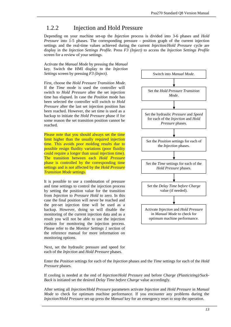
1.2.2 Injection and Hold Pressure
Depending on your machine set-up the Injection process is divided into 3-6 phases and Hold
Pressure into 1-5 phases. The corresponding pressure - position graph of the current injection
settings and the real-time values achieved during the current Injection/Hold Pressure cycle are
display in the Injection Settings Profile. Press F3 (Inject) to access the Injection Settings Profile
screen for a review of your settings.
Activate the Manual Mode by pressing the Manual key. Switch the HMI display to the Injection
Settings screen by pressing F3 (Inject).
First, choose the Hold Pressure Transition Mode.
If the Time mode is used the controller will
switch to Hold Pressure after the set injection
time has elapsed. In case the Position mode has
been selected the controller will switch to Hold
Pressure after the last set injection position has
been reached. However, the set time is used as a
backup to initiate the Hold Pressure phase if for
some reason the set transition position cannot be
reached.
Please note that you should always set the time
limit higher than the usually required injection
time. This avoids poor molding results due to
possible resign fluidity variations (poor fluidity
could require a longer than usual injection time).
The transition between each Hold Pressure
phase is controlled by the corresponding time
settings and is not affected by the Hold Pressure
Transition Mode settings.
It is possible to use a combination of pressure
and time settings to control the injection process
by setting the position value for the transition
from Injection to Pressure Hold to zero. In this
case the final position will never be reached and
the pre-set injection time will be used as a
backup. However, doing so will disable the
monitoring of the current injection data and as a
result you will not be able to use the injection
cushion for monitoring the injection process.
Please refer to the Monitor Settings 1 section of
the reference manual for more information on
monitoring options.
Next, set the hydraulic pressure and speed for
each of the Injection and Hold Pressure phases.
Enter the Position settings for each of the Injection phases and the Time settings for each of the Hold
Pressure phases.
If cooling is needed at the end of Injection/Hold Pressure and before Charge (Plasticizing)/Suck-
Back is initiated set the desired Delay Time before Charge value accordingly.
After setting all Injection/Hold Pressure parameters activate Injection and Hold Pressure in Manual Mode to check for optimum machine performance. If you encounter any problems during the
Injection/Hold Pressure set-up press the Manual key for an emergency reset to stop the operation.
Set the Hold Pressure Transition
Mode.
Set the hydraulic Pressure and Speed
for each of the Injection and Hold
Pressure phases.
Set the Position settings for each of
the Injection phases.
Set the Time settings for each of the
Hold Pressure phases.
Switch into Manual Mode.
Set the Delay Time before Charge
value (if needed).
Activate Injection and Hold Pressure
in Manual Mode to check for
optimum machine performance.
Pxa270 Standard Q8/M10M Version Manual
14
1.2.3 Charge (Plasticizing) and Suck-Back
Charge (Plasticizing) is divided into five phases and suck back. You can set the Backpressure and
Speed for each phase individually. Suck-back is initiated at the end of Charge (Plasticizing) if
required.
Press the Manual key to activate the Manual mode. Switch the HMI display to the Injection
Settings screen by pressing F4 (Charge).
First, set the Charge (Plasticizing) values for
Backpressure and Speed individually for each
phase.
Next, enter the Positions for the transition
between the five Charge (Plasticizing) phases.
If there is a control back pressure with the setting
value of pressure function, you can set the back
pressure in order to raise the density of the plastic
in the barrel.
You can choose Suck-Back mode at the F2 charge
page. Suck back mode has the option of suck back
after injection and suck back after cooling.
You can choose Suck-Back control mode at the F4
function page. Suck back control mode has the
time controlling and position controlling.
In addition, enter the Suck-back Speed and
Position/Time values. The same input field (below
the Suck-Back Pressure and Speed settings) is
used for both, the Time and the Position settings.
The field label will change according to the
selected mode to indicate the required value.
Set the Suck-back Press/Speed value to “0” if no
Suck-back is needed.
If cooling is needed after the injection hold pressure, please set the cooling before charging time.
Cooling timing:In case mold cooling is needed after completion of Charge/Suck-Back, please set
the cooling time as required.
In case cooling is needed after the completion of Charge (Plasticizing)/Suck-Back and before the
mold is opened enter the desired Cooling Time.
After setting all Charge (Plasticizing)/Suck-Back parameters activate Charge (Plasticizing) and
Suck-Back in Manual Mode to check for optimum machine performance. If you encounter any
problems during the Charge (Plasticizing)/Suck-Back set-up press the Manual key for an emergency
reset to stop the operation.
Set the Charge (Plasticizing) values
for Backpressure and Speed for each
phase.
Switch into Manual Mode.
Set the Suck-Back mode and Speed
and Position/Time values.
Set the Positions for the transition
between the three Charge
(Plasticizing) phases.
Activate Charge (Plasticizing)/Suck-
Back in Manual Mode to verify the
settings and to check for optimum
performance.
If needed set the Delay Time before
Charge and/or Cooling Time values.
Pxa270 Standard Q8 Version Manual
15
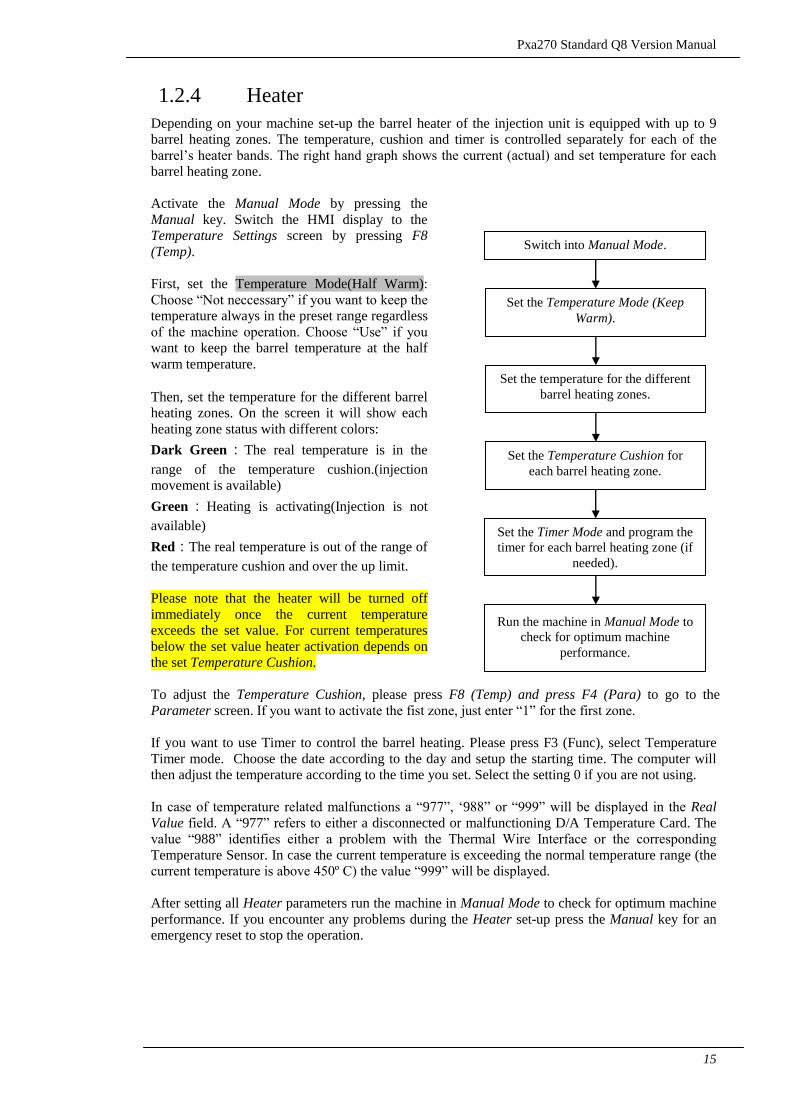
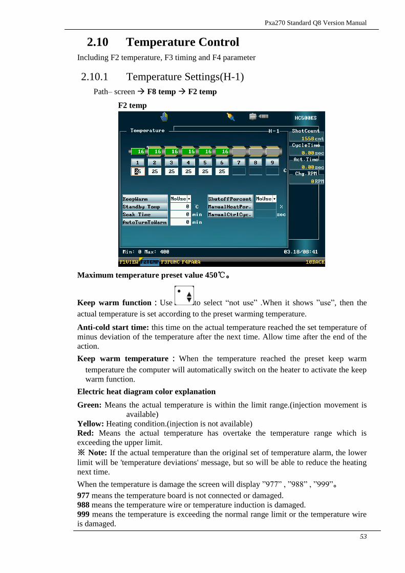
1.2.4 Heater
Depending on your machine set-up the barrel heater of the injection unit is equipped with up to 9
barrel heating zones. The temperature, cushion and timer is controlled separately for each of the
barrel‟s heater bands. The right hand graph shows the current (actual) and set temperature for each
barrel heating zone.
Activate the Manual Mode by pressing the
Manual key. Switch the HMI display to the
Temperature Settings screen by pressing F8
(Temp).
First, set the Temperature Mode(Half Warm):
Choose “Not neccessary” if you want to keep the
temperature always in the preset range regardless
of the machine operation. Choose “Use” if you
want to keep the barrel temperature at the half
warm temperature.
Then, set the temperature for the different barrel
heating zones. On the screen it will show each
heating zone status with different colors:
Dark Green:The real temperature is in the
range of the temperature cushion.(injection
movement is available)
Green:Heating is activating(Injection is not
available)
Red:The real temperature is out of the range of
the temperature cushion and over the up limit.
Please note that the heater will be turned off
immediately once the current temperature
exceeds the set value. For current temperatures
below the set value heater activation depends on
the set Temperature Cushion.
To adjust the Temperature Cushion, please press F8 (Temp) and press F4 (Para) to go to the
Parameter screen. If you want to activate the fist zone, just enter “1” for the first zone.
If you want to use Timer to control the barrel heating. Please press F3 (Func), select Temperature
Timer mode. Choose the date according to the day and setup the starting time. The computer will
then adjust the temperature according to the time you set. Select the setting 0 if you are not using.
In case of temperature related malfunctions a “977”, „988” or “999” will be displayed in the Real
Value field. A “977” refers to either a disconnected or malfunctioning D/A Temperature Card. The
value “988” identifies either a problem with the Thermal Wire Interface or the corresponding
Temperature Sensor. In case the current temperature is exceeding the normal temperature range (the
current temperature is above 450º C) the value “999” will be displayed.
After setting all Heater parameters run the machine in Manual Mode to check for optimum machine
performance. If you encounter any problems during the Heater set-up press the Manual key for an
emergency reset to stop the operation.
Set the Temperature Mode (Keep
Warm).
Set the temperature for the different
barrel heating zones.
Set the Temperature Cushion for
each barrel heating zone.
Set the Timer Mode and program the
timer for each barrel heating zone (if
needed).
Switch into Manual Mode.
Run the machine in Manual Mode to
check for optimum machine
performance.
Pxa270 Standard Q8/M10M Version Manual
16
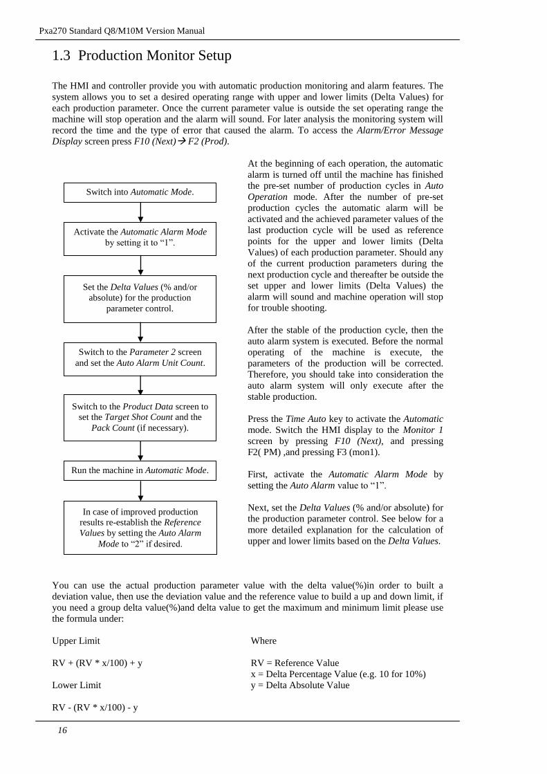
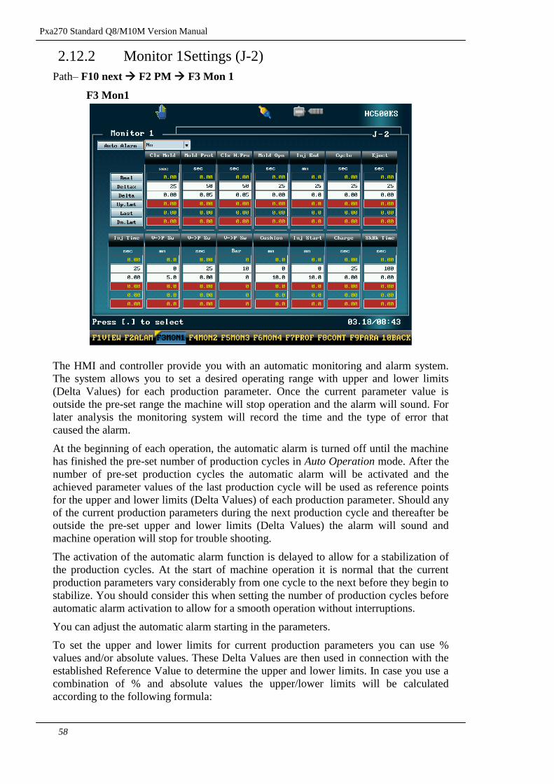
1.3 Production Monitor Setup
The HMI and controller provide you with automatic production monitoring and alarm features. The
system allows you to set a desired operating range with upper and lower limits (Delta Values) for
each production parameter. Once the current parameter value is outside the set operating range the
machine will stop operation and the alarm will sound. For later analysis the monitoring system will
record the time and the type of error that caused the alarm. To access the Alarm/Error Message Display screen press F10 (Next) F2 (Prod).
At the beginning of each operation, the automatic
alarm is turned off until the machine has finished
the pre-set number of production cycles in Auto
Operation mode. After the number of pre-set
production cycles the automatic alarm will be
activated and the achieved parameter values of the
last production cycle will be used as reference
points for the upper and lower limits (Delta
Values) of each production parameter. Should any
of the current production parameters during the
next production cycle and thereafter be outside the
set upper and lower limits (Delta Values) the
alarm will sound and machine operation will stop
for trouble shooting.
After the stable of the production cycle, then the
auto alarm system is executed. Before the normal
operating of the machine is execute, the
parameters of the production will be corrected.
Therefore, you should take into consideration the
auto alarm system will only execute after the
stable production.
Press the Time Auto key to activate the Automatic
mode. Switch the HMI display to the Monitor 1
screen by pressing F10 (Next), and pressing
F2( PM) ,and pressing F3 (mon1).
First, activate the Automatic Alarm Mode by
setting the Auto Alarm value to “1”.
Next, set the Delta Values (% and/or absolute) for
the production parameter control. See below for a
more detailed explanation for the calculation of
upper and lower limits based on the Delta Values.
You can use the actual production parameter value with the delta value(%)in order to built a
deviation value, then use the deviation value and the reference value to build a up and down limit, if
you need a group delta value(%)and delta value to get the maximum and minimum limit please use
the formula under:
Upper Limit Where
RV + (RV * x/100) + y RV = Reference Value
x = Delta Percentage Value (e.g. 10 for 10%) Lower Limit y = Delta Absolute Value
RV - (RV * x/100) - y
Activate the Automatic Alarm Mode
by setting it to “1”.
Switch into Automatic Mode.
Switch to the Parameter 2 screen
and set the Auto Alarm Unit Count.
Set the Delta Values (% and/or
absolute) for the production
parameter control.
Switch to the Product Data screen to
set the Target Shot Count and the
Pack Count (if necessary).
Run the machine in Automatic Mode.
In case of improved production
results re-establish the Reference
Values by setting the Auto Alarm
Mode to “2” if desired.
Pxa270 Standard Q8 Version Manual
17
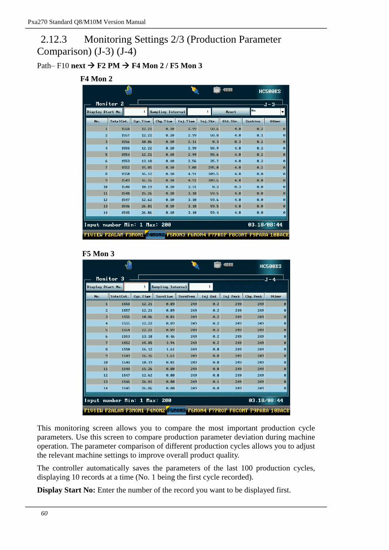
Since the Reference Values are not fixed and vary from one machine operation cycle to the next the
values are lost once the machine is turned off. They will be re-established at the beginning of the
next operation cycle by using the current parameter values to determine the new reference points for
the upper and lower limits (Delta Values).
Under the Auto Alarm mode, if the Auto Alarm had already been activated (mode 1) or if the
necessary number of production cycle for establishing the reference values has not yet been reached
(mode 0), you can adjust the cycle numbers for Auto Alarm mode please press F8 enter into the
parameters screen and insert the data you required.
Run the machine in automatic mode after setting all parameters until the activation of the Auto
Alarm mode to verify the setting and to check for optimum performance. In case of improved
production results after the activation of the Auto Alarm mode re-establish the Reference Value in
Monitor 1 screen.
Pxa270 Standard Q8/M10M Version Manual
18
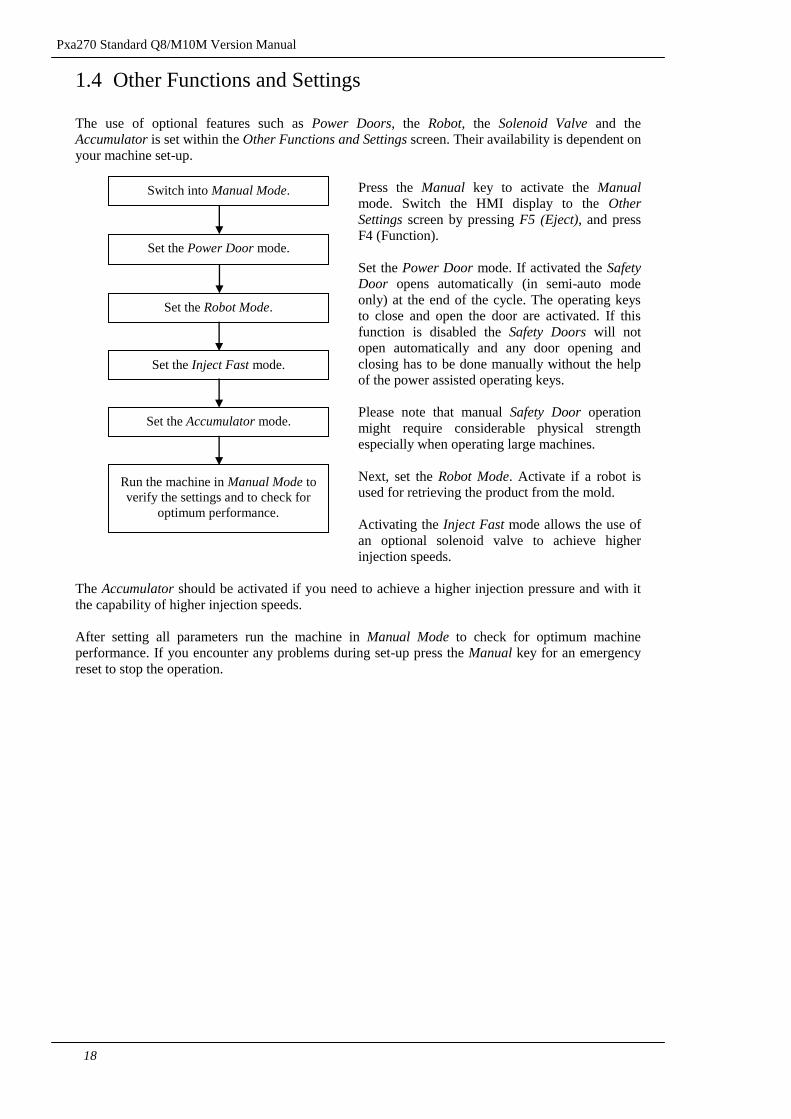
1.4 Other Functions and Settings
The use of optional features such as Power Doors, the Robot, the Solenoid Valve and the
Accumulator is set within the Other Functions and Settings screen. Their availability is dependent on
your machine set-up.
Press the Manual key to activate the Manual mode. Switch the HMI display to the Other
Settings screen by pressing F5 (Eject), and press
F4 (Function).
Set the Power Door mode. If activated the Safety Door opens automatically (in semi-auto mode
only) at the end of the cycle. The operating keys
to close and open the door are activated. If this
function is disabled the Safety Doors will not
open automatically and any door opening and
closing has to be done manually without the help
of the power assisted operating keys.
Please note that manual Safety Door operation
might require considerable physical strength
especially when operating large machines.
Next, set the Robot Mode. Activate if a robot is
used for retrieving the product from the mold.
Activating the Inject Fast mode allows the use of
an optional solenoid valve to achieve higher
injection speeds.
The Accumulator should be activated if you need to achieve a higher injection pressure and with it
the capability of higher injection speeds.
After setting all parameters run the machine in Manual Mode to check for optimum machine
performance. If you encounter any problems during set-up press the Manual key for an emergency
reset to stop the operation.
Set the Power Door mode.
Switch into Manual Mode.
Set the Inject Fast mode.
Set the Robot Mode.
Set the Accumulator mode.
Run the machine in Manual Mode to
verify the settings and to check for
optimum performance.
Pxa270 Standard Q8 Version Manual
19
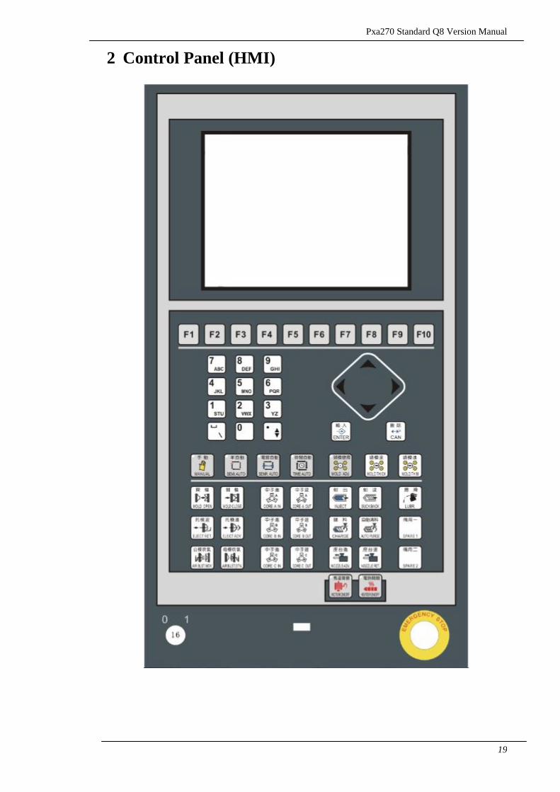
2 Control Panel (HMI)
Pxa270 Standard Q8/M10M Version Manual
20
2.1 Control Panel and Keys
The Control Panel is covered with a protective Mylar layer to make the panel water, dirt
and abrasion resistant. All keys are operated through type A mechanical contact
switches to provide for reliability and a long service life.
2.1.1 Machine Control Panel Keys
The machine control panel keys allow you to switch between different machine
operating modes and to manually control the operation of the machine. Nevertheless,
even most manual commands will be executed using the stored machine settings. It is
therefore important that you verify the settings first to ensure safe machine operation.
Pxa270 Standard Q8 Version Manual
21
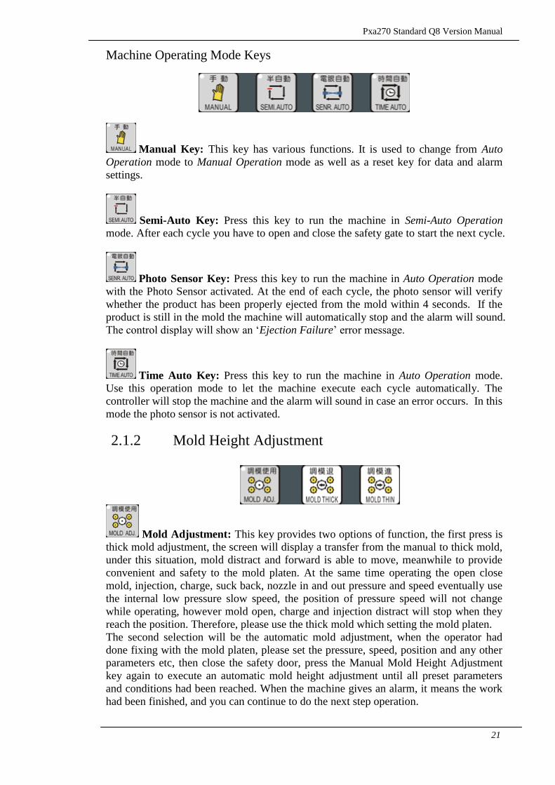
Machine Operating Mode Keys
Manual Key: This key has various functions. It is used to change from Auto
Operation mode to Manual Operation mode as well as a reset key for data and alarm
settings.
Semi-Auto Key: Press this key to run the machine in Semi-Auto Operation
mode. After each cycle you have to open and close the safety gate to start the next cycle.
Photo Sensor Key: Press this key to run the machine in Auto Operation mode
with the Photo Sensor activated. At the end of each cycle, the photo sensor will verify
whether the product has been properly ejected from the mold within 4 seconds. If the
product is still in the mold the machine will automatically stop and the alarm will sound.
The control display will show an „Ejection Failure‟ error message.
Time Auto Key: Press this key to run the machine in Auto Operation mode.
Use this operation mode to let the machine execute each cycle automatically. The
controller will stop the machine and the alarm will sound in case an error occurs. In this
mode the photo sensor is not activated.
2.1.2 Mold Height Adjustment
Mold Adjustment: This key provides two options of function, the first press is
thick mold adjustment, the screen will display a transfer from the manual to thick mold,
under this situation, mold distract and forward is able to move, meanwhile to provide
convenient and safety to the mold platen. At the same time operating the open close
mold, injection, charge, suck back, nozzle in and out pressure and speed eventually use
the internal low pressure slow speed, the position of pressure speed will not change
while operating, however mold open, charge and injection distract will stop when they
reach the position. Therefore, please use the thick mold which setting the mold platen.
The second selection will be the automatic mold adjustment, when the operator had
done fixing with the mold platen, please set the pressure, speed, position and any other
parameters etc, then close the safety door, press the Manual Mold Height Adjustment
key again to execute an automatic mold height adjustment until all preset parameters
and conditions had been reached. When the machine gives an alarm, it means the work
had been finished, and you can continue to do the next step operation.
Pxa270 Standard Q8/M10M Version Manual
22
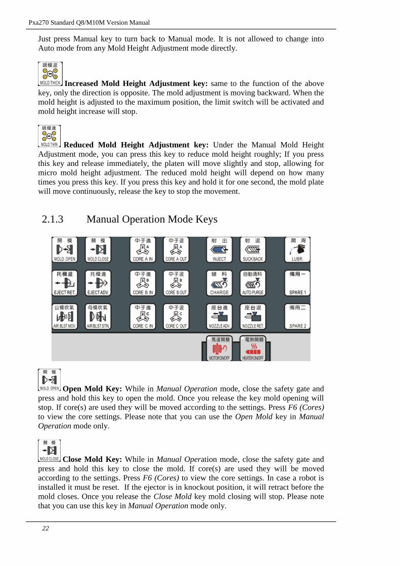
Just press Manual key to turn back to Manual mode. It is not allowed to change into
Auto mode from any Mold Height Adjustment mode directly.
Increased Mold Height Adjustment key: same to the function of the above
key, only the direction is opposite. The mold adjustment is moving backward. When the
mold height is adjusted to the maximum position, the limit switch will be activated and
mold height increase will stop.
Reduced Mold Height Adjustment key: Under the Manual Mold Height
Adjustment mode, you can press this key to reduce mold height roughly; If you press
this key and release immediately, the platen will move slightly and stop, allowing for
micro mold height adjustment. The reduced mold height will depend on how many
times you press this key. If you press this key and hold it for one second, the mold plate
will move continuously, release the key to stop the movement.
2.1.3 Manual Operation Mode Keys
Open Mold Key: While in Manual Operation mode, close the safety gate and
press and hold this key to open the mold. Once you release the key mold opening will
stop. If core(s) are used they will be moved according to the settings. Press F6 (Cores)
to view the core settings. Please note that you can use the Open Mold key in Manual
Operation mode only.
Close Mold Key: While in Manual Operation mode, close the safety gate and
press and hold this key to close the mold. If core(s) are used they will be moved
according to the settings. Press F6 (Cores) to view the core settings. In case a robot is
installed it must be reset. If the ejector is in knockout position, it will retract before the
mold closes. Once you release the Close Mold key mold closing will stop. Please note
that you can use this key in Manual Operation mode only.
Pxa270 Standard Q8 Version Manual
23
Ejector Retraction Key: Use this key in Manual Operation mode to retract the
ejector. Ejector movement will stop once the key has been released or the back limit has
been reached. Please note that you can use this key in Manual Operation mode only.
Ejector Activation Key: Use this key in Manual Operation mode to activate the
ejector. Before the ejector can be activated the mold has to be opened completely, all
cores have to be retracted and the ejector has to be positioned between the limit
switches. The ejector will be activated according to the Ejector settings. Press F5 (Eject)
to view the settings. Please note that you can use Ejector Activation key in Manual
Operation mode only. If necessary press the Manual key for an emergency reset to stop
the operation.
Air Blast Moving Platen Key: Use this key in Manual Operation mode to
activate the air blast for the moving platen. The current air blast settings will be used.
Press F5 (Eject) to view the settings. Please note that you can use this key in Manual
Operation mode only. If necessary press the Manual key for an emergency reset to stop
the operation.
Air Blast Static Platen Key: Use this key in Manual Operation mode to
activate the air blast for the static platen. The current air blast settings will be used.
Press F5 (Eject) to view the settings. Please note that you can use this key in Manual
Operation mode only. If necessary press the Manual key for an emergency reset to stop
the operation.
Core A In Core A Out Keys: Press the Core A In key to enter the core
function option. Press the core in or core out key under the manual mode any core
movement will be executed according to the current settings at any position of the open
and close mold.
Core B In Core B Out: Selection of the function of Core B, press the
core in or core out key under the manual mode any core movement will be executed
according to the current settings at any position of the open and close mold.
Core C In Core C Out: Selection of the function of Core C, press the
core in or core out key under the manual mode any core movement will be executed
according to the current settings at any position of the open and close mold.
Injection Key: Under the manual mode, when the temperature is “ON”, the
barrel‟s temperature had reached and had also reach the preset temperature value. Press
Pxa270 Standard Q8/M10M Version Manual
24
this key to inject and during the movement, the set value will enter into pressure
protection according to different stages then enter into the end of the pressure protection
pressure and speed. Once u release this key then the injection will stop.
Suck back Key: Press this key to retract the ejector. Ejector movement will stop
once the key has been released or the back limit has been reached.
Charge (Plasticizing) Key: Use this key in Manual Operation mode to charge
the injection unit. Press and release this key to start charging (plasticizing). The
operation is automatically stopped once charging has been completed. If necessary,
press and release the Charge (Plasticizing) key again to stop charging immediately. If
Suck-Back is required the controller will initiate Suck-Back automatically according to
the current settings. Press F3 (InjSpc) to view the settings.
Please note that you can use this key in Manual Operation mode only.
Auto Purge Key: While in Manual Operation mode, press this key to activate
Auto Purge. The current Auto Purge settings will be used. Press F3 (InjSpc) to view the
settings. Please note that you can use this key in Manual Operation mode only. If
necessary press the Manual key for an emergency reset to stop the operation.
Nozzle Advance Key: Press and hold this key in Manual Operation mode to
move the nozzle and injection unit forward. Release the key to stop movement. Please
make sure the nozzle advance limit switch (located on the machine) is activated to
prevent damage as a result of the nozzle colliding with the mold. For safety reasons the
nozzle and injection unit will slow down once it is moving close to the mold.
Please note that you can use this key in Manual Operation mode only.
Nozzle Retraction Key: Press and hold this key in Manual Operation mode to
retract the nozzle and injection unit. Release the key to stop movement. Please note that
the nozzle retraction limit switch is deactivated during this operation to permit
maximum injection unit movement. This allows for easy cleaning and maintenance. The
nozzle retraction limit switch is only activated while using auto operation modes. Please
note that you can use this key in Manual Operation mode only.
Hydraulic Pump Motor On/Off Key: Press this key in Manual Operation
mode to start the hydraulic pump motor (customer installed), press it again to stop the
motor. Please note that you can use this key in Manual Operation mode only.
Heater On/Off Key: Press this key in Manual Operation mode to start heating
the barrel, press it again to stop heating the barrel. The heater will use the current barrel
Pxa270 Standard Q8 Version Manual
25
heating settings. Press F8 (Temp) to view the settings. Please note that you can use this
key in Manual Operation mode only.
Lubrication Key: Press and hold this key in Manual Operation mode to start
the lubrication oil pump (customer installed). Release the key to stop the pump. Please
note that you can use this key in Manual Operation mode only.
Pxa270 Standard Q8/M10M Version Manual
26
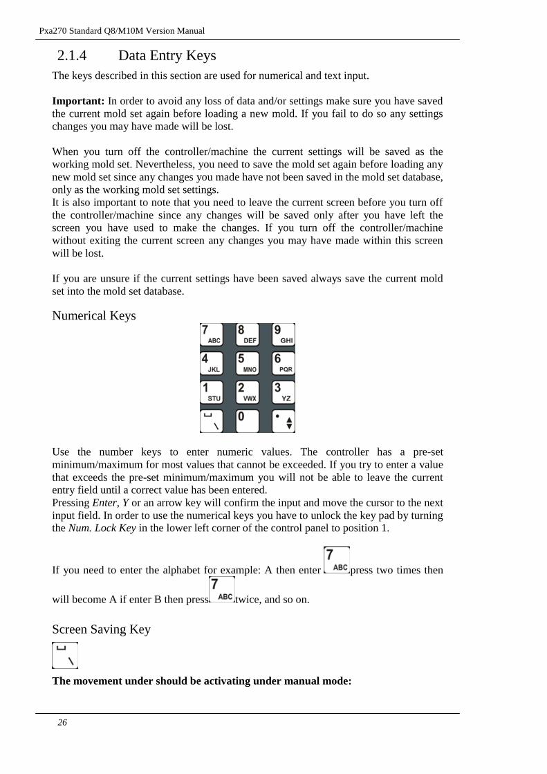
2.1.4 Data Entry Keys
The keys described in this section are used for numerical and text input.
Important: In order to avoid any loss of data and/or settings make sure you have saved
the current mold set again before loading a new mold. If you fail to do so any settings
changes you may have made will be lost.
When you turn off the controller/machine the current settings will be saved as the
working mold set. Nevertheless, you need to save the mold set again before loading any
new mold set since any changes you made have not been saved in the mold set database,
only as the working mold set settings.
It is also important to note that you need to leave the current screen before you turn off
the controller/machine since any changes will be saved only after you have left the
screen you have used to make the changes. If you turn off the controller/machine
without exiting the current screen any changes you may have made within this screen
will be lost.
If you are unsure if the current settings have been saved always save the current mold
set into the mold set database.
Numerical Keys
Use the number keys to enter numeric values. The controller has a pre-set
minimum/maximum for most values that cannot be exceeded. If you try to enter a value
that exceeds the pre-set minimum/maximum you will not be able to leave the current
entry field until a correct value has been entered.
Pressing Enter, Y or an arrow key will confirm the input and move the cursor to the next
input field. In order to use the numerical keys you have to unlock the key pad by turning
the Num. Lock Key in the lower left corner of the control panel to position 1.
If you need to enter the alphabet for example: A then enter press two times then
will become A if enter B then press twice, and so on.
Screen Saving Key
The movement under should be activating under manual mode:
Pxa270 Standard Q8 Version Manual
27
1. inserts the SD card or USB to the machine.
2. turn to the screen of printing,press this button twice .
Next, “ER: loading MMC card” will appear at the left bottom column,it means the
printing is in the process.
3. A screen will pop up from the window in about 2 or 3 seconds which means that
the printing is in process and will be save into SD/MMC card,after that press
to confirm.
4 insert SD/MMC card and connected to the pc machine,enter print file,in side the
file it include the screen that after printing.
ATTN:User can use different language to process the actions above
Input Dialog Box Confirm/Cancel Keys
Enter key : After the insert of the value, press this enter key to indicate the saving
other data, press once the enter key to move the cursors to the other position. This key
is able to represent the direction key.
Warning: Before you renew the mold platen, if you want to change any set documents,
you have to resave the mold data again. If you did not do so, the new data will disappear.
Cancel key : Pressing this key cancels the changes you may have made within the
current field and resets the current value to “0”.
Arrow Keys:
Arrow Keys: Use the arrow keys to change the current field selection and to move the
cursor. Please note that the arrow keys move the cursor only within the current column
(up/down) or line (left/right). If the field you are trying to select does not overlap with
the currently selected column or line using the arrow keys will not allow you to jump to
the desired field unless you use a combination of left/right and up/down movements you
can use the enter key to reach the desired position.
Pxa270 Standard Q8/M10M Version Manual
28
Notice:After you change the data and willing to move the cursors to another position,
the original data after corrections will be saved.
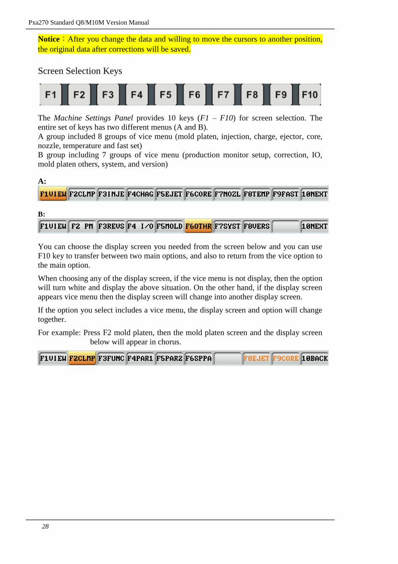
Screen Selection Keys
The Machine Settings Panel provides 10 keys (F1 – F10) for screen selection. The
entire set of keys has two different menus (A and B).
A group included 8 groups of vice menu (mold platen, injection, charge, ejector, core,
nozzle, temperature and fast set)
B group including 7 groups of vice menu (production monitor setup, correction, IO,
mold platen others, system, and version)
A:
B:
You can choose the display screen you needed from the screen below and you can use
F10 key to transfer between two main options, and also to return from the vice option to
the main option.
When choosing any of the display screen, if the vice menu is not display, then the option
will turn white and display the above situation. On the other hand, if the display screen
appears vice menu then the display screen will change into another display screen.
If the option you select includes a vice menu, the display screen and option will change
together.
For example: Press F2 mold platen, then the mold platen screen and the display screen
below will appear in chorus.
Pxa270 Standard Q8 Version Manual
29
2.2 HMI Display
2.2.1 Screen Selection
To access any of the screens described in this section please use this graphic as a
reference:
F1
View
F2
CLMP
F1
VIEW
F2
CLMP
F3
FUNC
F4
PARA1
F5
PARA2
F6
SPPA
F8
EJET
F9
CORE
F10
BACK
F3
INJE
F1
VIEW
F2
INJE
F3
FUNC
F4
PROF
F5
PARA
F6
SPPA
F8
CHRG
F9
NOZL
F10
BACK
F4
CHRG
F1
VIEW
F2
CHAG
F3
PURG
F4
FUNC
F5
PARA
F6
SPPA
F8
INJE
F9
NOZL
F10
BACK
F5
EJET
F1
VIEW
F2
EJET
F3
BLST
F4
FUNC
F5
PARA
F6
F8
CLMP
F9
CORE
F10
BACK
F6
CORE
F1
VIEW
F2
COR1
F3
COR2
F4
COR3
F5
FUNC
F6
PARA
F8
CLMP
F9
EJET
F10
BACK
F7
NOZL
F1
VIEW
F2
NOZL
F3
PARA
F7
INJE
F8
CHRG
F9
CLMP
F10
BACK
F8
TEMP
F1
VIEW
F2
TEMP
F3
TIME
F4
PARA
F10
BACK
F9
FAST
F1
VIEW
F2
FAST
F3
ADJM
F4
PARA
F6
CLMP
F7
INJE
F8
CHRG
F9
EJET
F10
BACK
F10
NEXT
F1
VIEW
F2
PM
F1
VIEW
F2
ALAM
F3
MON1
F4
MON2
F5
MON3
F6
PROF
F7
CONT
F8
PARA
F10
BACK
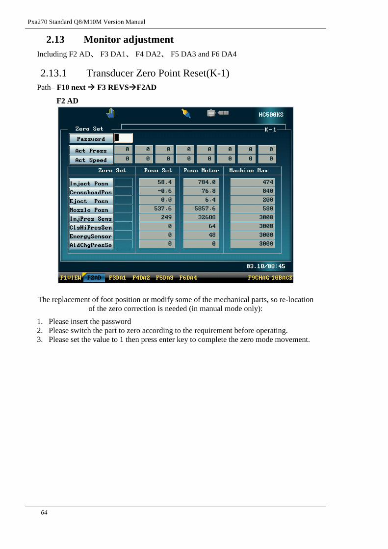
F3
REVS
F1
VIEW
F2
AD
F3
DA1
F4
DA2
F5
DA3
F6
DA4
F9
CHRG
F10
NEXT
F4
I/O
F1
VIEW
F2
PB1
F3
PB2
F4
PC1
F5
PC2
F6
A IO
F7
PA
F8
DIAG
F10
BACK
F5
MOLD
F1
VIEW
F2
MLDS
F3
MLDR
F4
MLDC
F5
MLDD
F6
MACH
F7
RECD
F10
BACK
F6
OTHR
F7
SYST
F1
VIEW
F2
SYST
F3
CONF
F4
DATA
F5
REST
F6
SEQN
F6
INST
F10
BACK
F8
VERS
F10
BACK
F10
NEXT
F10
BACK
For a more detailed explanation of how to use the screen selection keys (F1 through F10)
please refer to the Screen Selection Keys section of this manual.
Pxa270 Standard Q8/M10M Version Manual
30
2.3 Control Panel(A-1)
Warning: Situation display above, mold platen name, motor movement situation, open
mold total amount timing and at the below part had point out the date, time of display
key will be shown in any of the screen
Screen & Mold
data Name
Barrel current
temperature and
heating condition
Communication
identity
pressure, Flow
Injection Position,
Injection Start, and
Cushion
Date and time
Screen Menu Oil Temperature
The motor icon will
appear here if the
hydraulic motor is
turned on.
Status display
machine
Display the
position of the
mold and ejector
Mold opening total
counter display after
the auto cycle
finished.
Total time display
during the auto cycle.
Rotation speed of
charging
Page
Number
Pxa270 Standard Q8 Version Manual
31
2.4 Clamp Settings
include F2 Mold, F3 Function, F4 Para1 , F5 Para2 and F6 Sppa
2.4.1 Clamp open/close mold settings(B-1)
Path- Main screen F2 mold F2 mold
F2 Mold
Mold Opening Stroke: Sets the distance the mold will travel between mold closed and
mold open positions.
Mold Opening and Closing Settings: Mold Closing and Mold Opening is divided into
3 phases each. Pressure and speed settings can be adjusted separately for each phase.
The transition between each phase is controlled by the corresponding position settings.
The corresponding Mold Closing and Mold Opening profiles are displayed in the
Pressure-Position Graphs on the right hand side (Mold Closing top, Mold Opening
bottom).
Auto Cycle Delay Time: The delay time between molding cycles, usually for robot use.
Pxa270 Standard Q8/M10M Version Manual
32
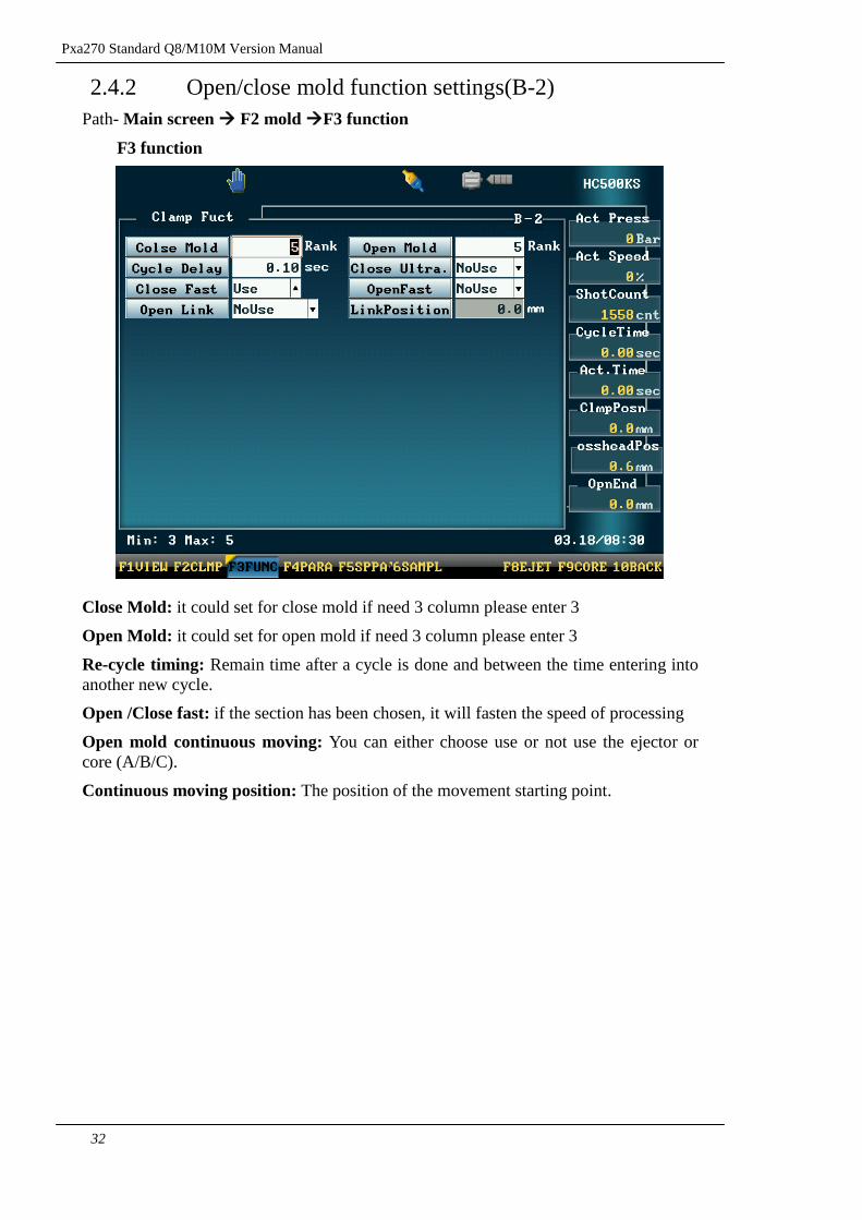
2.4.2 Open/close mold function settings(B-2)
Path- Main screen F2 mold F3 function
F3 function
Close Mold: it could set for close mold if need 3 column please enter 3
Open Mold: it could set for open mold if need 3 column please enter 3
Re-cycle timing: Remain time after a cycle is done and between the time entering into
another new cycle.
Open /Close fast: if the section has been chosen, it will fasten the speed of processing
Open mold continuous moving: You can either choose use or not use the ejector or
core (A/B/C).
Continuous moving position: The position of the movement starting point.
Pxa270 Standard Q8 Version Manual
33
2.4.3 Open/ close mold parameters settings(B-3)
Path- Main screen F2 mold F4 PARA
F4 PARA
This photo including Clamp Settings and all the other parameters (detail information
please referral to the Para chart)
Pxa270 Standard Q8/M10M Version Manual
34
2.4.4 Open /close mold Special parameters(B-4)
Path- Main screen F2 mold F5 SPPA
F5 SPPA
Pxa270 Standard Q8 Version Manual
35
2.5 Injection settings
Including F2 injection, F3 function, F4 profile, F5 parameter and F6 Sppa
2.5.1 Injection Settings(C-1)
Path- Main screen F3 Inje F2 Injection
F2 Injection
Injection and hold pressure: Due to the injection control, it is divided into injection
and hold pressure, injection is divided into 4 stages, each stages has its own pressure
and speed setup , transition of each stages is used according to the position distance to
transit the pressure and speed, it‟s is suitable for different kinds of complicated , high
precision mold platen , however injection hold pressure is available to transit by time, or
by using position transit or both, the perform is due to the consideration of the mold
platen‟s formation , the flowing and efficiency of the raw materials, there are many
different ways to modulate but all the modulation are basically included.
Hold pressure used three stages of pressure, speed, transition is function according
to the position of time or pressure, until the last timing was done, it means that the
injection procedure is completed and continues by the next step.
The user can also use the permanent injection timing to inject by setting the hold
pressure position to zero, to prevent the hold pressure to reach the transition point, the
manual injection time is equal to the actual injection time however the sensor function
will be lost, and the low quality products will be hard to discover and lack of
immediate modulation.
Due to the difference of flowing of every mold barrel, the smaller the variation is
the higher the products quality will be, therefore the computer will check during the
starting point of the injection , the injection movement timing and the sensor part .
Please take notice that the alarm will be alert when the limit is overtaken.
Hold pressure transform: Pressure protection after the injection is mainly divided in
to 3 types.
Position selection will be made after the hold pressure reach the position; times
selection will be made when the injection time reach the transformed hold pressure;
pressure selection is made when the hold pressure reach the transformed hold pressure
Pxa270 Standard Q8/M10M Version Manual
36
hold pressure:The transformation way selection: Under the pressure condition this
setup is available.
Injection time: The injection time is normally longer than the actual time, it is because
when the hold pressure reached its transit point the computer will stop the injection time,
therefore when the raw material flowing is not in the best condition, the actual timing
will be longer, and the transit point will reach later, however during the good condition
of the raw material flowing the transit point will reach efficiently, at the moment the
actual timing will be shorter. In order to differentiate both of these, we provide a highest
and lowest limit, it means that the actual timing of injection should not overtake the
limit it is because the production out of this scope will be considered as bad quality
products.
When the hold pressure transform is using the injection position controller, when the
injection of 6 stages position ends when the screw is reached , it is transform to the
hold pressure, if the point is not reached, then the transform will happen when the
upper limit time is reached. Therefore, this time setting value will normally be longer
then the injection timing, when the transform timing is selected the 4 stages end
position will not be displayed, and the upper limit 000.0mm will change to
movement000.0sec, at the moment the injection will activate according to the time set.
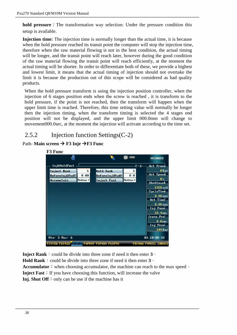
2.5.2 Injection function Settings(C-2)
Path- Main screen F3 Inje F3 Func
F3 Func
Inject Rank:could be divide into three zone if need it then enter 3。
Hold Rank:could be divide into three zone if need it then enter 3。
Accumulator:when choosing accumulator, the machine can reach to the max speed。
Inject Fast:If you have choosing this function, will increase the valve
Inj. Shut Off:only can be use if the machine has it
Pxa270 Standard Q8 Version Manual
37
2.5.3 Injection Profile Settings(C-3)
Path- Main screen F3 Inje F4 Prof
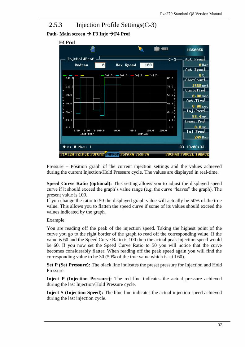
F4 Prof
Pressure – Position graph of the current injection settings and the values achieved
during the current Injection/Hold Pressure cycle. The values are displayed in real-time.
Speed Curve Ratio (optional): This setting allows you to adjust the displayed speed
curve if it should exceed the graph‟s value range (e.g. the curve “leaves” the graph). The
present value is 100.
If you change the ratio to 50 the displayed graph value will actually be 50% of the true
value. This allows you to flatten the speed curve if some of its values should exceed the
values indicated by the graph.
Example:
You are reading off the peak of the injection speed. Taking the highest point of the
curve you go to the right border of the graph to read off the corresponding value. If the
value is 60 and the Speed Curve Ratio is 100 then the actual peak injection speed would
be 60. If you now set the Speed Curve Ratio to 50 you will notice that the curve
becomes considerably flatter. When reading off the peak speed again you will find the
corresponding value to be 30 (50% of the true value which is still 60).
Set P (Set Pressure): The black line indicates the preset pressure for Injection and Hold
Pressure.
Inject P (Injection Pressure): The red line indicates the actual pressure achieved
during the last Injection/Hold Pressure cycle.
Inject S (Injection Speed): The blue line indicates the actual injection speed achieved
during the last injection cycle.
Pxa270 Standard Q8/M10M Version Manual
38
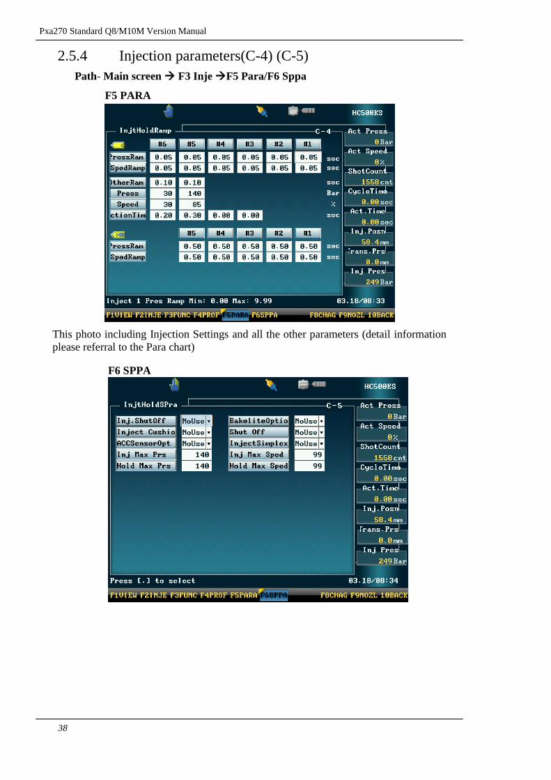
2.5.4 Injection parameters(C-4) (C-5)
Path- Main screen F3 Inje F5 Para/F6 Sppa
F5 PARA
This photo including Injection Settings and all the other parameters (detail information
please referral to the Para chart)
F6 SPPA
Pxa270 Standard Q8 Version Manual
39
2.6 Charge (plasticizing) and suck-back settings
Including F2 charge、F3 cleaning、F4 function、F5 parameters and F6Sppa
2.6.1 Charge and suck-back settings(D-1)
Path– screen F4 charge F2 charge
F2 charge
Charge setting: Charging process, a total of 5 stages of pressure, speed control, are free
to set its start, the necessary pressure and the speed and location at the last and middle
paragraph.
Suck back setting: Suck back setting of pressure speed is divided into position or time.
If position is selected you only need to insert the suck back distance, if you are not
using the suck back please set the time and position to 0.
Cool Delay: Reserve before the cooling time can also be done before the charge is
expected to use the cooling function.
Cool Time: After injection began cooling time.
Pxa270 Standard Q8/M10M Version Manual
40
2.6.2 Automatic barrel clean-up settings(D-2)
Path– screen F4 charge F3 cleaning
F3 cleaning
Cleaning frequency: According to the actual demand to setup the cleaning frequency,
the maximum setup is 99 times.
Notice:When the machine is activating the production normally, if the screw last
position is too big (current location) after the product is completed. When the
operator is willing to correct the value, changing of the corresponding data is
according to the charging and injection. However this function could simplify the
operation if only to insert the final position of the injection at the correction
column and select use at the “remain storage corrections” column to complete the
auto correction of all the charging injection position.
Time: According to the actual demand to setup the cleaning time.
Pxa270 Standard Q8 Version Manual
41
2.6.3 Charge function settings(D-3)
Path– screen F4 charge F4 function
F4 function
Charge: The Rank setting of charge
Charge back pressure valve:You can either choose output or not output during the
charge back pressure valve.
Suck back control mode: When the selection of the suck back time control is selected,
the suck back position settings column unit will change to time which means suck back
movement timing settings are available.
Suck back control before charging: Selection of time and position control is
available during the suck back movement before charging.
Charging control once again: Selection of position and time control is available
during charging before injection.
Pxa270 Standard Q8/M10M Version Manual
42
2.6.4 Charging parameters settings(D-4) (D-5)
Path – screen F4 charge F5 parameters / F6 Sppa
F5 parameters
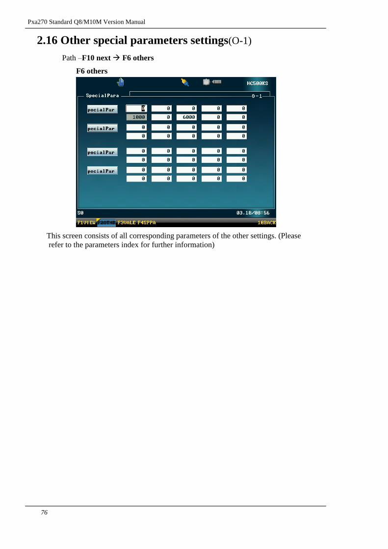
This screen consists of all corresponding parameters during charging settings. (Please
refer to the parameters index for further information)
F6 Sppa
Pxa270 Standard Q8 Version Manual
43
2.7 Ejector
Including F2 Ejector、F3 Blast 、F4 Function and F5 Parameters
2.7.1 Ejector settings(E-1)
Path- Main screen F5 EJET F2 EJET
F2 EJET
Ejector settings:
The initial ejection is divided into two phases that can be controlled separately. You can
set pressure, speed and activation position individually for each phase. If you require
additional cooling of the mold product after mold opening set the delay time for ejector
activation accordingly.
Ejector mode:Ejector mode consists of 3 different kind of options ;
Stop:Use this function when ejector stop, uniformly used under semi auto mode,
automatic mode is not available, the thimble will push then stop to await for the
extraction of the production, the thimble will only move backward after the
power door is closed . After the thimble movement then the close mold will
activate.
Frequency:The ejector frequency is count according to the setup value of the ejector
frequency.
Vibration:It is the ejector vibration, the thimble will rely on the frequency set and
will activate a short term high speed backward and forward ejection when the
forward ejector reach the end which will cause a vibration and a fall off of the
production(the vibration time please refer to the ejector column)
Eject Count (Ejection Count): The number of times the ejector will be activated.
Setting this value to “0” will deactivate the ejector.
Position: Set here the end position for ejector retraction between repeated activation (in
case of multiple ejector activation). Please note this position is relative to the absolute
retraction end position that is used after final ejector activation and determined by the
transducer zero point setting.
Pxa270 Standard Q8/M10M Version Manual
44
2.7.2 Air Blast Settings(E-2)
Path- Main screen F5 EJET F3 BLST
F3 BLST
Blast :We provide fixed-blowing activities template (optional), which included A, B,
C, D, E, F group blasting to control the position of the action point, timing delay of the
blasting time. If the ejection is done, mold close will only be activated after the blasting
is completed.
Pxa270 Standard Q8 Version Manual
45
2.7.3 Ejector function settings(E-3)
Path – screen F5 EJET F4 FUNC
F4 FUNC
Robot: In order to operate with the automatic production of the production department,
therefore robot is used to replace the workers to extract the injection products. Therefore
after every completion of open mold the robot will automatically extract the products.
Besides, in order to protect the mold platen and the robot the computer of our company
will ensure that the robot has returned to its position in reserve before the close mold
then close mold will be activate.
Automatic power door: If there is an installment of pneumatic or oil pressure power
door, selection of this function should be set if not the power door key on the operating
panel will be insufficient.
Manual:Manual air blow, Example:when set=0,press this key then move
platen air blow。When set=1,
Enter this key then C set air blow。setting=2, press this key then E set air
blow。
Pxa270 Standard Q8/M10M Version Manual
46
2.7.4 Ejector Parameters(E-5)
Path- Main screen F5 EJET F6 PARA
F6 PARA
This photo including Ejector Settings and all the other parameters (detail information
please referral to the Para chart)
Pxa270 Standard Q8 Version Manual
47
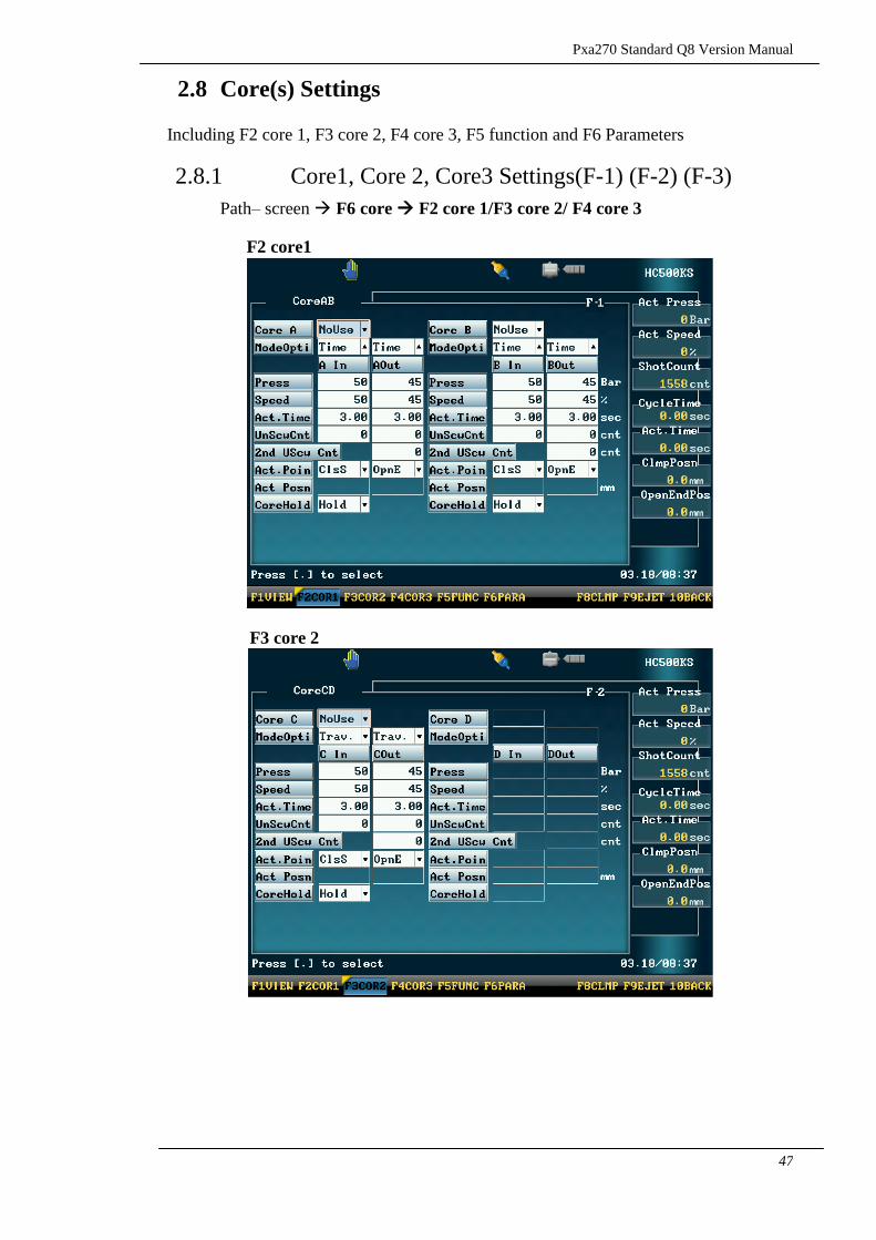
2.8 Core(s) Settings
Including F2 core 1, F3 core 2, F4 core 3, F5 function and F6 Parameters