12
EN CMC-TC Transponder Handle for TS 8 with Integral Legic Reader DK 7320.781 Assembly, Installation and Operation A 37175 08 IT 74
EN CMC-TC Transponder Handle for TS 8 with Integral Legic Reader
DK 7320.781
Assembly, Installation and Operation
A 37175 08 IT 74

Microsoft Windows is a registered trademark of Microsoft Corporation.
Acrobat Reader is a registered trademark of Adobe Systems Incorporated.

Documentation Notes 1
CMC-TC Transponder Handle for TS 8 with Integral Legic Reader 3
ENTable of Contents
1 Documentation Notes....................... 4
1.1 Associated documents ........................4
1.2 Retention of the documents ................4
1.3 Used symbols ......................................4
2 Safety Notes ...................................... 4
3 Unit Description ................................ 5
3.1 Enclosure.............................................5
3.1.1 TS 8 comfort handle with integral Legic reader ....................5
3.1.2 Legic unit .............................................5
3.1.3 Transponder card ................................5
3.2 Power supply .......................................5
3.3 System requirements...........................5
3.4 Scope of supply ...................................5
3.5 Accessories .........................................5
3.5.1 Required accessories ..........................5
3.6 Proper use ...........................................6
4 Assembly ........................................... 7
4.1 Assembly notes ...................................7
4.2 Assembling CMC-TC...........................7
4.2.1 Assembly with the mounting module...7
4.2.2 Assembly with Velcro fasteners ..........7
4.2.3 Assembly with 1 U mounting unit ........7
5 Installation......................................... 8
5.1 Safety and other notes ........................8
5.2 Installation variant 1 (PU) ....................8
5.3 Installation variant 2 (AU) ....................8
6 Commissioning ................................. 9
6.1 Commissioning variant 1 (PU).............9
6.2 Commissioning variant 2 (AU)...........10
7 Operation......................................... 10
8 Storage............................................. 10
9 Disposal ........................................... 10
10 Customer Service ........................... 10
11 Technical Specifications ................ 10
12 Maintenance and Cleaning............. 11
12.1.1 Cleaning ............................................11

1 Documentation Notes
CMC-TC Transponder Handle for TS 8 with Integral Legic Reader 4
EN 1 Documentation Notes The audience for this guide is the technical special-ists familiar with the assembly, installation and op-eration of the CMC-TC.
• You should read this operating guide prior to the commissioning and store the guide so it is readily accessible for subsequent use.
Rittal cannot accept any liability for damage and operational malfunctions that result from the non-observance of this guide.
1.1 Associated documents
The guides for other CMC-TC components and their safety notes also apply together with this guide.
This guide is also provided as a file on the accom-panying CD-ROM:
German: 7320100VXXd.pdf
English: 7320100VXXe.pdf
To view the guide you require the Acrobat Reader program; Acrobat Reader can be downloaded from www.adobe.com
You can download current firmware updates and operating guides from www.rimatrix5.de.
1.2 Retention of the documents
This guide and all associated documents are part of the product. They must be given to the operator of the unit and must be stored so they are available when needed.
1.3 Used symbols
The following safety and other notes are used in this guide:
Symbol for a handling instruction:
• This bullet point indicates that you should perform an action.
Safety and other notes:
Danger! Immediate danger to health and life!
Warning! Possible danger for the product and the environment!
Note! Useful information and special features.
2 Safety Notes Observe the subsequent general safety notes for the installation and operation of the unit:
− Assembly and installation, in particular for wiring the enclosures with mains power, may be per-formed only by a trained electrician. Other tasks associated with the CMC-TC, such as the as-sembly and installation of system components with tested standard connectors, and the opera-tion and configuration of the CMC-TC may be performed only by instructed personnel.
− Observe the valid regulations for the electrical installation for the country in which the unit is in-stalled and operated, and the national regula-tions for accident prevention. Also observe any company-internal regulations (work, operating and safety regulations).
− Prior to working at the CMC-TC system, it must be disconnected from the power supply and pro-tected against being switched on again.
− Use only genuine spare parts and accessories approved by the manufacturer that serve to en-sure the safety of the unit. The use of other parts can void the liability for any resulting con-sequences.
− Do not make any changes to the CMC-TC that are not described in this guide or in the associ-ated guides.
− Only the prescribed network cables may be used operationally (see page 10, “Technical Specifications”).
− The operational safety of the unit is guaranteed only for its approved use. The limit values stated in the technical specifications (see page 10, “Technical Specifications”) may not be ex-ceeded under any circumstances. In particular, this applies to the permitted ambient tempera-ture range and to the permitted IP protection category. When used with a higher required IP protection category, the Rittal CMC-TC must be installed in a housing or enclosure with a higher IP protection category appropriate for the re-quired IP protection category.
− The operation of the CMC-TC system in direct contact with water, aggressive materials or in-flammable gases and vapours is prohibited.
− In addition to these general safety notes, also observe any special safety notes listed for the specific tasks in the individual sections.

Unit Description 3
CMC-TC Transponder Handle for TS 8 with Integral Legic Reader 5
EN3 Unit Description The CMC-TC comfort handle for TS 8 with integral Legic reader system consists of three components:
3.1 Enclosure
3.1.1 TS 8 comfort handle with integral Legic reader
This is a Rittal TS 8 comfort handle with an integral Legic reader in the lower part of the handle. All en-closures equipped with a TS 8 comfort handle can also be equipped with the comfort handle with inte-gral Legic reader. Only holes on the enclosure door for accepting the cables must be made.
3.1.2 Legic unit
Abb. 1 CMC-TC Legic unit front side
Key
1 Power supply LED
The Legic unit is located in a standard housing of the CMC-TC. The housing is installed in the 1 U mounting unit or in the enclosure using the mounting bracket. An LED (1) which indicates the presence of mains power is located on the front side of the unit.
Abb. 2 CMC-TC Legic unit rear side
Key
2 Antenna connection
3 “Ant” connection
4 “IOIO” connection
5 “P-I²-C” connection
6 DIP switch
The antenna connection (2) is located on the rear side of the housing. The antenna connection is marked with a Y character. The "Ant" connection (3) is reserved for the handle connection. The "IOIOI" connection (4) is used for connecting to the Processing Unit. The "P-I²-C" connection (5) is used for connecting to the CMC-TC Access Unit. The ten DIP switches (6) are used to code the op-erational variant. For coding, see chapter 4.1 “Assembly notes”.
3.1.3 Transponder card
All Legic transponder media that have a carrier fre-quency of 13.56 MHz can be used.
3.2 Power supply
The power supply is established using the connec-tion to the CMC-TC system.
3.3 System requirements
− 1 Processing Unit II (7320.100) with software version as of 2.30
− 1 Access Unit (7320.220)
− 1 Access Sensor (7320.530)
− 2 RJ45 connection cables (7320.470) (for variant 2)
− 1 RJ45 connection cable (7320.470) (for variant 2)
− 1 RJ12 connection cable (7320.814) (for variant 1)
3.4 Scope of supply
The unit will be delivered in a packaging unit in fully-assembled state.
• Check the delivered components for complete-ness.
• Check that the packaging does not show any signs of damage.
Scope of supply
1 Legic unit
1
TS8 comfort handle with inte-grated Legic reader, including assembly kit and connection cables
3 Transponder boards
1 RJ12 connection cable (RJ12 connector to Molex connector)
1 Antenna connection cable (socket to plug)
Tab. 1 Lieferumfang
3.5 Accessories
3.5.1 Required accessories
Depending on the country-specific specifications, you require an appropriate connection cable for the power pack of the CMC-TC Processing Unit II.
1
2 5
6 4 3

3 Unit Description
CMC-TC Transponder Handle for TS 8 with Integral Legic Reader 6
EN
Acces-sories
Designation Packs of
Re-quired
Model No.
Installation power pack 24 V IEC
100-230 V AC, UL approval, 3 A SELV
1 7320.425
Power supply
Installation power pack 24 V IEC
48 V DC 1
Yes, depend-ing on power supply
7320.435
Connection cable IEC con-nector
Country version D
1 7200.210
Connection cable IEC con-nector
Country version GB
1
7200.211
Connection cable IEC con-nector
Country version F/B
1
7200.210
Connection cable IEC con-nector
Country version CH
1
7200.213
Connection cable IEC con-nector
Country version USA/CDN, UL approval FT1/VW1
1
7200.214
Connec-tion cable for power pack
Extension cable IEC connector and socket
1
Yes, 1x for power pack
7200.215
1 U mounting unit
1 7320.440
1 U single moun-ting unit with strain relief
1 Optional
7320.450
Installa-tion
1 cable clamp strap
1 Only for 1 U mounting unit (7320.440)
7611.000
Program-ming cable
Programming cable D-Sub 9 to RJ 11
1 Yes, max. 1
7200.221
Connec-tion cable
RJ45 connection cable
4 Yes, 2 units
7320.470
cable RJ12 connection cable
2 Yes, 1x 7320.814
Processing Unit II
1 Yes, 1x 7320.100
Units
Access Unit 1 Yes, 1x 7320.220
Tab. 2 Required accessories
3.6 Proper use
The Rittal CMC-TC Legic system serves as an en-closure monitoring system for the monitoring and administration of various enclosure parameters.
A use different from that described here is consid-ered to be an improper use. Rittal cannot accept any liability for damage resulting from the improper use or the non-observance of this guide. The guides for the used accessories may apply.

Assembly 4
CMC-TC Transponder Handle for TS 8 with Integral Legic Reader 7
EN4 Assembly
4.1 Assembly notes
Install the CMC-TC system in an enclosure or in a suitable housing system so that it also has addi-tional protection from external effects. Also consider the permitted ambient temperature and humidity operational areas and the application-related re-quired IP degree of protection (see page 10, “Technical Specifications”).
Note! The system can be integrated in the CMC-TC system in two different variants. For variant 1, all 16 digits of the card number are fetched and compared with the authorisation database. In this case, the system can analyse exactly which card owner has initiated a door release.
For variant 2, the transponder card fet-ches only the final four digits of the card. This variant, however, can represent a safety risk. For example, the final four digits of the card number can be identical for two transponder cards. In this case the system cannot analyse which card owner has initiated a door release.
Note! Because the wiring differs, decide prior to the installation of the CMC-TC Legic sys-tem which variant you require. The follow-ing pages explain the two assembly vari-ants.
4.2 Assembling CMC-TC
4.2.1 Assembly with the mounting module
Abb. 3 Assembly with the mounting module
• Move the CMC-TC Legic unit on the retaining plate of the mounting module. Ensure that the re-
taining plate sits between the guide rails of the CMC-TC Legic unit.
4.2.2 Assembly with Velcro fasteners
Abb. 4 Assembly with Velcro fasteners
• Take the self-adhesive Velcro fasteners from the supplied accessories and remove the protective foil from the Velcro fasteners.
• Ensure that the adhesion surfaces are free from grease and dust.
• Attach the Velcro fasteners to the housing of the CMC-TC Legic unit and position the CMC-TC Le-gic unit at the required attachment location.
4.2.3 Assembly with 1 U mounting unit
2,4
1,5
3
Abb. 5 Assembly with 1 U mounting unit
1. Remove the two upper screws of the trim piece.
2. Remove the trim piece.
3. Move the CMC-TC Legic unit on the retaining plate of the mounting unit. Ensure that the re-taining plate sits between the guide rails of the CMC-TC Legic unit.
4. Replace the trim piece on the mounting unit.
5. Screw the trim piece back on the 1 U mounting unit.
5 Installation
CMC-TC Transponder Handle for TS 8 with Integral Legic Reader 8
EN 5 Installation
Danger! The assembly and installation may be performed only by trained specialists.
5.1 Safety and other notes
− The Rittal CMC-TC system may be operated only with connected protective earth conductor. The protective earth conductor connection is made by plugging in the IEC connection cable. This requires that the IEC connection cable at the power supply side be connected with the protective earth conductor.
− The electrical connection voltage and frequency must conform to the rated values specified at the rear of the housing and in the technical specifications (see page 10, “Technical Specifi-cations”).
− Before commencing work on the Rittal CMC-TC system, it must be disconnected from the mains power supply and protected against being re-connected.
− Protect the connection cables using cable ties on the used housing or enclosure.
− To prevent unnecessary cable losses, the used cable lengths must not exceed the lengths specified in the technical specifications (see page 10 “Technical Specifications”).
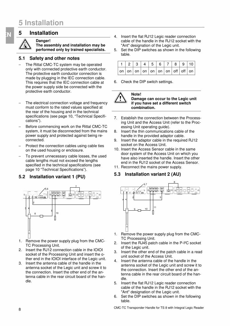
5.2 Installation variant 1 (PU)
1. Remove the power supply plug from the CMC-TC Processing Unit.
2. Insert the RJ12 connection cable in the IOIOI socket of the Processing Unit and insert the o-ther end in the IOIOI interface of the Legic unit.
3. Insert the antenna cable of the handle in the antenna socket of the Legic unit and screw it to the connection. Insert the other end of the an-tenna cable in the rear circuit board of the han-dle.
4. Insert the flat RJ12 Legic reader connection
cable of the handle in the RJ12 socket with the "Ant" designation of the Legic unit.
5. Set the DIP switches as shown in the following table.
1 2 3 4 5 6 7 8 9 10
on on on on on on on off off on
6. Check the DIP switch settings.
Note! Damage can occur to the Legic unit if you have set a different switch combination.
7. Establish the connection between the Process-
ing Unit and the Access Unit (refer to the Proc-essing Unit operating guide).
8. Insert the thin communications cable of the handle in the provided adaptor cable.
9. Insert the adaptor cable in the required RJ12 socket on the Access Unit.
10. Insert the Access Sensor cable in the same door system of the Access Unit on which you have also inserted the handle. Insert the other end in the RJ12 socket of the Access Sensor.
11. Reconnect the mains power supply.
5.3 Installation variant 2 (AU)
1. Remove the power supply plug from the CMC-TC Processing Unit.
2. Insert the RJ45 patch cable in the P-I²C socket of the Legic unit.
3. Insert the other end of the patch cable in a read unit socket of the Access Unit.
4. Insert the antenna cable of the handle in the antenna socket of the Legic unit and screw it to the connection. Insert the other end of the an-tenna cable in the rear circuit board of the han-dle.
5. Insert the flat RJ12 Legic reader connection cable of the handle in the RJ12 socket with the "Ant" designation of the Legic unit.
6. Set the DIP switches as shown in the following table.
5,6
Power
24 VDC max. 2,5 A I0I0I
1 P-I C 2 1 2 4 3
10 9
8
4 3
2
7 Power
24 VDC max. 2,5 A I0I0I
1 P-I C 2 1 2
4 3
8 6,7
9 10
5
11
4 3 2

Commissioning 6
CMC-TC Transponder Handle for TS 8 with Integral Legic Reader 9
EN
1 2 3 4 5 6 7 8 9 10
on on on on on on on on off off
7. Check the DIP switch settings.
Note! Damage can occur to the Legic unit if you have set a different switch combination.
8. Establish the connection between the Process-
ing Unit and the Access Unit (refer to the Proc-essing Unit operating guide).
9. Insert the thin communications cable of the handle in the provided adaptor cable.
10. Insert the adaptor cable in the required RJ12 socket on the Access Unit.
11. Insert the access sensor cable in the Access Unit.
12. Reconnect the mains power supply.
6 Commissioning
6.1 Commissioning variant 1 (PU)
1. Use the text editor to create an empty file with the name "access.cmc".
2. Open the text editor and write the command: "kaba_mpr=1". Save this file with the name "op-tions.cmc".
3. Open the command prompt on your computer. 4. Log on with FTP to the Processing Unit (refer to
the Processing Unit operating guide). 5. Go to the upload directory. 6. Send the two files to the Processing Unit. 7. Reboot by removing and reinserting the mains
plug of the Processing Unit. Wait until the boot operation has completed. This is indicated with the operation LED of the Processing Unit.
8. Hold each card successively in front of the Legic reader on the handle. The beeping sound con-firms the successful reading.
9. Open the command prompt on your computer. 10. Log on with FTP to the Processing Unit. 11. Go to the "upload" directory. 12. Copy the "kaba.codes" file to your computer. 13. Use the text editor to open the "kaba.codes" file
on your computer. 14. The following example shows the typical ap-
pearance of the file:
Card identification num-ber
Door ope-
ning
„0123456789012345“ , „0000“
„0123456789012346“ , „0000“
15. Change the door release as required.
"1234..." , "0102" = user
User identifi-cation: this optional ma-ximum 8-digit decimal num-ber (10000-99999999) can be used to specify whether a user identifi-cation will be sent with the trap mes-sage.
Separator: ´=´
Door release: this 4-digit number contains a decimal number 0...3 for each of the four possible Access Units. This number specifies which door is to be re-leased: 0 – do not release any door 1 – release door 1 2 – release door 2 3 – release door 1 and 2 This number must always contain four digits, irrespec-tive of how many Access Units are connected; a '0' must be specified for any Access Units that are not present.
Separator: ´,´
The card identification number of the transponder cards must not be changed.
16. Confirm each input at the line end by pressing
the Enter key. 17. The file you created could have the following
appearance.
Card identification num-ber
Door ope-
ning
„0123456789012345“ , „0001“
„0123456789012346“ , „0221“
18. Save the changed file with the name "ac-cess.cmc" on your hard disk.
19. Use FTP to copy the new "access.cmc" file to the Processing Unit.
20. Reboot the system by removing and reinserting the power supply plug.
7 Operation
CMC-TC Transponder Handle for TS 8 with Integral Legic Reader 10
EN 6.2 Commissioning variant 2 (AU)
1. Open the command prompt on your computer. 2. Log on with FTP to the Processing Unit (refer to
the Processing Unit operating guide). 3. Go to the upload directory. 4. Delete the "access.cmc" and "options.cmc" files. 5. Close the command prompt. 6. Open the web browser on your computer. 7. Enter the current IP address of the Processing
Unit. 8. Log on to the Processing Unit. 9. Click the tool icon for the Access Unit. 10. Click Access Codes. 11. Enter the final four card digits in the list and set
the door release. 12. To confirm, click Accept.
7 Operation Hold the transponder card in front of the Legic han-dle. The card detection will issue an acoustic signal on the handle. If the card code is correct, the door handle will be released after 1-2 seconds. To open the door, press the silver-coloured button on the handle to release the handle lever.
If the card code is not correct, the door remains locked.
8 Storage If the device is not used for a longer period, we rec-ommend that the device is disconnected from the mains power supply and is protected from damp-ness and dust.
Further information concerning the operating condi-tions is contained in the technical specifications.
9 Disposal Because the CMC-TC Processing Unit consists primarily of the housing and PCB, the unit must be disposed of through the electronic waste recycling system when it is no longer required.
10 Customer Service If you have any technical questions or questions concerning our product spectrum, contact the follow-ing service address:
Tel.: +49 (0)2772/505-1855 http://www.rimatrix5.de E-mail: [email protected]
Note!
To allow us to process your enquiry quickly and correctly, please always spe-cify the article number in the subject line for e-mails.
Further information and the current operating guides and updates of the Rittal CMC-TC are available for download under Security on the Rimatrix5 home-page.
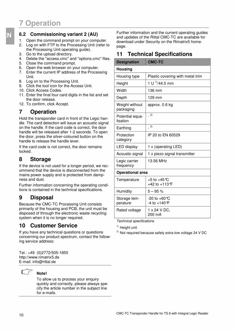
11 Technical Specifications
Designation CMC-TC
Housing
Housing type Plastic covering with metal trim
Height 1 U 1)
/44.5 mm
Width 136 mm
Depth 129 mm
Weight without packaging
approx. 0.6 kg
Potential equa-lisation
- 2)
Earthing - 2)
Protection category
IP 20 to EN 60529
LED display 1 x (operating LED)
Acoustic signal 1 x piezo signal transmitter
Legic carrier frequency
13.56 MHz
Operational area
Temperature +5 to +45°C +42 to +113°F
Humidity 5 – 95 %
Storage tem-perature
-20 to +60°C -4 to +140°F
Rated voltage 1 x 24 V DC, 200 mA
Technical specifications
1) Height unit
2) Not required because safety extra-low voltage 24 V DC
Maintenance and Cleaning 12
CMC-TC Transponder Handle for TS 8 with Integral Legic Reader 11
EN
12 Maintenance and Cleaning The Rittal CMC-TC Legic unit is a maintenance-free system. The housing does not need to be opened for the installation or during operation.
Note!
Opening the housing or any accessory components will void any warranty and liability claims.
12.1.1 Cleaning
Warning!
Danger of damage! Do not use any aggressive sub-stances, such as white spirit, acid, etc., for cleaning because such sub-stances can damage the unit.
Use a slightly moistened soft cloth to clean the housing.


