SNOW CAB FOR TORO WHEEL HORSE 260 Series & XT Series TRACTORS MODEL 79970 OPERATION - PARTS LIST - ASSEMBLY IMPORTANT You must remove the doors and vinyl cover from the frame of the cab before transporting the machine on an open trailer or in an open truck, whose speed will exceed 25 MPH. ! IMPORTANT! READ THIS OPERATION MANUAL CAREFULLY AND KEEP FOR FUTURE REFERENCE FORM 10440/70 1200REV
Transcript
SNOW CAB FOR TORO WHEEL HORSE
260 Series & XT Series TRACTORS
MODEL 79970
OPERATION - PARTS LIST - ASSEMBLY
IMPORTANT
You must remove the doors and vinyl cover from the frame of the cab before transporting the machine on an open trailer or in an open truck, whose speed will
exceed 25 MPH.
! IMPORTANT! READ THIS OPERATION MANUAL CAREFULLY AND KEEP FOR FUTURE REFERENCE
FORM 10440/70 1200REV
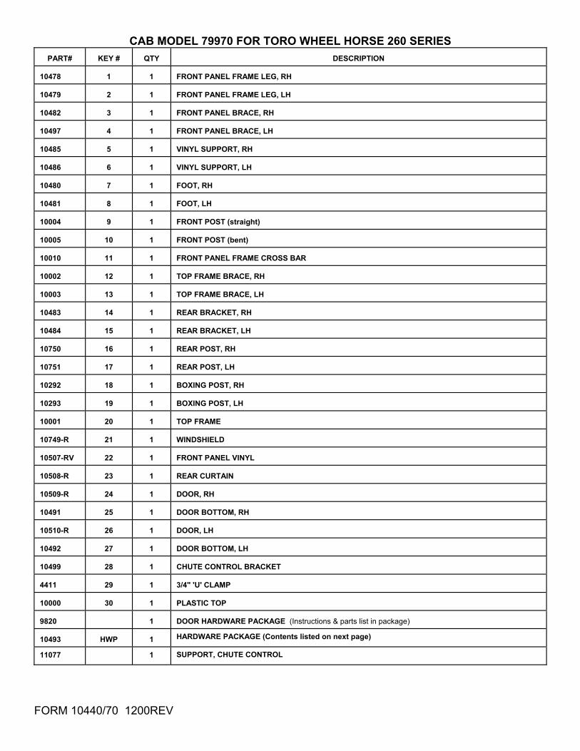
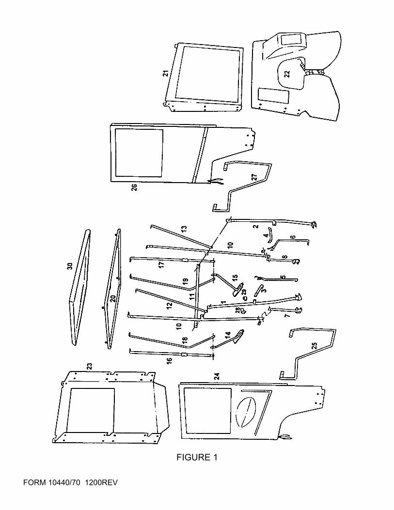
CAB MODEL 79970 FOR TORO WHEEL HORSE 260 SERIES
PART#
KEY #
QTY
DESCRIPTION 10478
1
1
FRONT PANEL FRAME LEG, RH
10479
2
1
FRONT PANEL FRAME LEG, LH
10482
3
1
FRONT PANEL BRACE, RH
10497
4
1
FRONT PANEL BRACE, LH
10485
5
1
VINYL SUPPORT, RH
10486
6
1
VINYL SUPPORT, LH
10480
7
1
FOOT, RH
10481
8
1
FOOT, LH
10004
9
1
FRONT POST (straight)
10005
10
1
FRONT POST (bent)
10010
11
1
FRONT PANEL FRAME CROSS BAR
10002
12
1
TOP FRAME BRACE, RH
10003
13
1
TOP FRAME BRACE, LH
10483
14
1
REAR BRACKET, RH
10484
15
1
REAR BRACKET, LH
10750
16
1
REAR POST, RH
10751
17
1
REAR POST, LH
10292
18
1
BOXING POST, RH
10293
19
1
BOXING POST, LH
10001
20
1
TOP FRAME
10749-R
21
1
WINDSHIELD
10507-RV
22
1
FRONT PANEL VINYL
10508-R
23
1
REAR CURTAIN
10509-R
24
1
DOOR, RH
10491
25
1
DOOR BOTTOM, RH
10510-R
26
1
DOOR, LH
10492
27
1
DOOR BOTTOM, LH
10499
28
1
CHUTE CONTROL BRACKET
4411
29
1
3/4" 'U' CLAMP
10000
30
1
PLASTIC TOP
9820
1
DOOR HARDWARE PACKAGE (Instructions & parts list in package)
10493
HWP
1 HARDWARE PACKAGE (Contents listed on next page)
11077 1 SUPPORT, CHUTE CONTROL
FORM 10440/70 1200REV
FIGURE 1
FORM 10440/70 1200REV
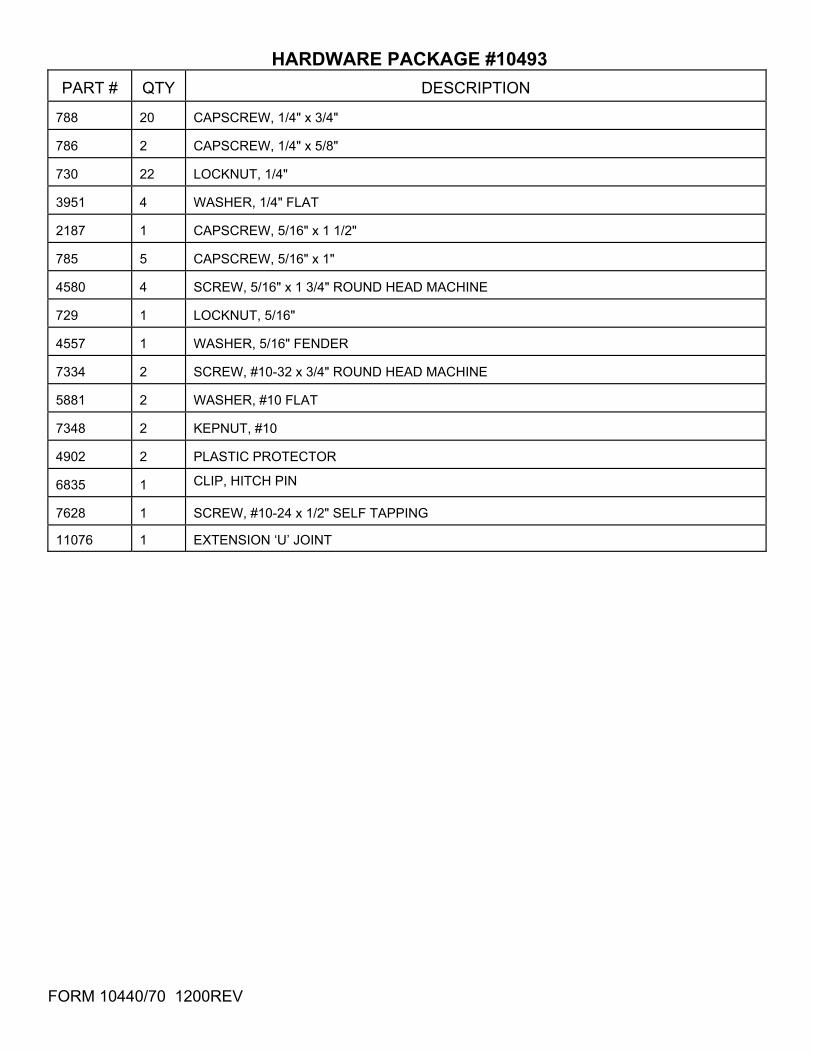
HARDWARE PACKAGE #10493 PART #
QTY
DESCRIPTION
788
20
CAPSCREW, 1/4" x 3/4"
786
2
CAPSCREW, 1/4" x 5/8"
730
22
LOCKNUT, 1/4"
3951
4
WASHER, 1/4" FLAT
2187
1
CAPSCREW, 5/16" x 1 1/2"
785
5
CAPSCREW, 5/16" x 1"
4580
4
SCREW, 5/16" x 1 3/4" ROUND HEAD MACHINE
729
1
LOCKNUT, 5/16"
4557
1
WASHER, 5/16" FENDER
7334
2
SCREW, #10-32 x 3/4" ROUND HEAD MACHINE
5881
2
WASHER, #10 FLAT
7348
2
KEPNUT, #10
4902
2
PLASTIC PROTECTOR
6835
1 CLIP, HITCH PIN
7628
1
SCREW, #10-24 x 1/2" SELF TAPPING
11076 1 EXTENSION ‘U’ JOINT
FORM 10440/70 1200REV
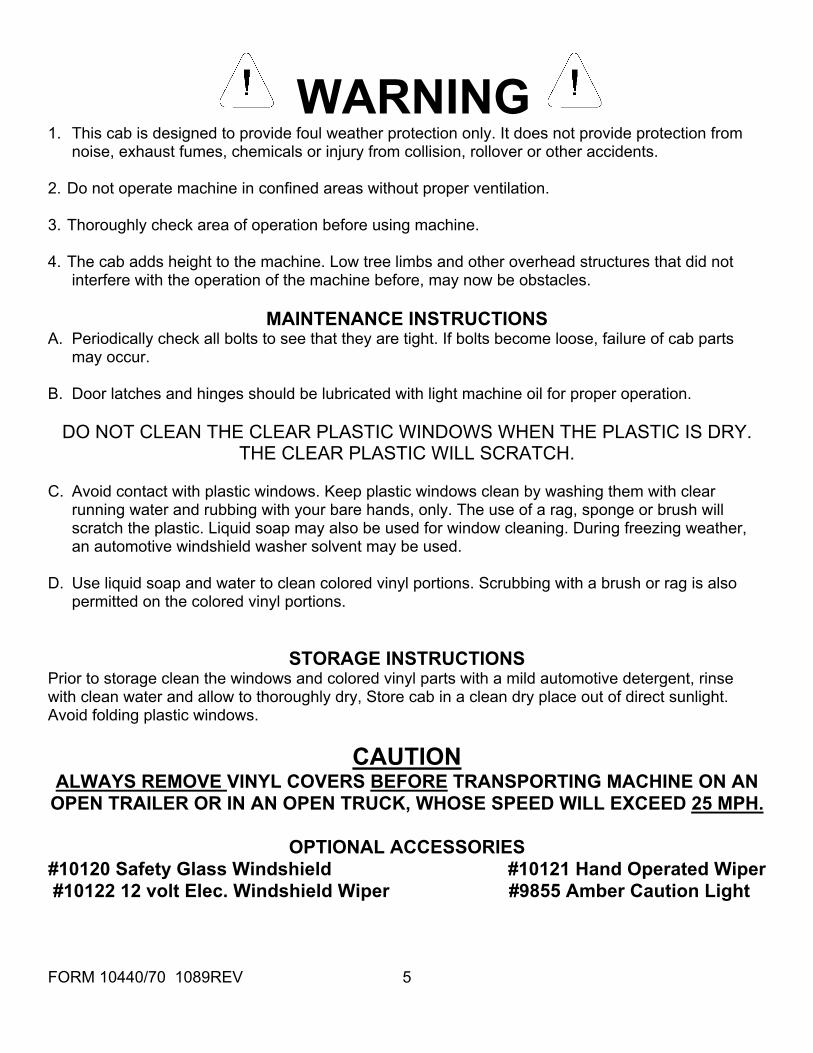
WARNING 1. This cab is designed to provide foul weather protection only. It does not provide protection from
noise, exhaust fumes, chemicals or injury from collision, rollover or other accidents. 2. Do not operate machine in confined areas without proper ventilation. 3. Thoroughly check area of operation before using machine. 4. The cab adds height to the machine. Low tree limbs and other overhead structures that did not
interfere with the operation of the machine before, may now be obstacles.
MAINTENANCE INSTRUCTIONS A. Periodically check all bolts to see that they are tight. If bolts become loose, failure of cab parts
may occur. B. Door latches and hinges should be lubricated with light machine oil for proper operation.
DO NOT CLEAN THE CLEAR PLASTIC WINDOWS WHEN THE PLASTIC IS DRY. THE CLEAR PLASTIC WILL SCRATCH.
C. Avoid contact with plastic windows. Keep plastic windows clean by washing them with clear
running water and rubbing with your bare hands, only. The use of a rag, sponge or brush will scratch the plastic. Liquid soap may also be used for window cleaning. During freezing weather, an automotive windshield washer solvent may be used.
D. Use liquid soap and water to clean colored vinyl portions. Scrubbing with a brush or rag is also
permitted on the colored vinyl portions.
STORAGE INSTRUCTIONS Prior to storage clean the windows and colored vinyl parts with a mild automotive detergent, rinse with clean water and allow to thoroughly dry, Store cab in a clean dry place out of direct sunlight. Avoid folding plastic windows.
CAUTION ALWAYS REMOVE VINYL COVERS BEFORE TRANSPORTING MACHINE ON AN
OPEN TRAILER OR IN AN OPEN TRUCK, WHOSE SPEED WILL EXCEED 25 MPH.
OPTIONAL ACCESSORIES #10120 Safety Glass Windshield #10121 Hand Operated Wiper #10122 12 volt Elec. Windshield Wiper #9855 Amber Caution Light
FORM 10440/70 1089REV 5
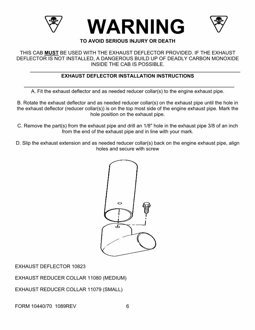
WARNING TO AVOID SERIOUS INJURY OR DEATH
THIS CAB MUST BE USED WITH THE EXHAUST DEFLECTOR PROVIDED. IF THE EXHAUST
DEFLECTOR IS NOT INSTALLED, A DANGEROUS BUILD UP OF DEADLY CARBON MONOXIDE INSIDE THE CAB IS POSSIBLE.
EXHAUST DEFLECTOR INSTALLATION INSTRUCTIONS
A. Fit the exhaust deflector and as needed reducer collar(s) to the engine exhaust pipe.
B. Rotate the exhaust deflector and as needed reducer collar(s) on the exhaust pipe until the hole in the exhaust deflector (reducer collar(s)) is on the top most side of the engine exhaust pipe. Mark the
hole position on the exhaust pipe.
C. Remove the part(s) from the exhaust pipe and drill an 1/8" hole in the exhaust pipe 3/8 of an inch from the end of the exhaust pipe and in line with your mark.
D. Slip the exhaust extension and as needed reducer collar(s) back on the engine exhaust pipe, align
READ THESE INSTRUCTIONS COMPLETELY BEFORE BEGINNING INSTALLATION.
THE RIGHT SIDE OF THE TRACTOR IS DETERMINED FROM THE
OPERATORS SEATED POSITION.
The word "BOLT" will refer to a 1/4" x 3/4" capscrew and the word "NUT" will refer to a 1/4" lock nut while using these installation instructions.
B. Place the RH VINYL SUPPORT [5] on the step plate. Insert a #10 x 3/4" round head machine screw with a #10 flat washer through the bent flattened end of the part and down into the step plate. Secure with a #10 kepnut.
OPTIONAL STEPS FOR SNOWBLOWER ATTACHMENTS Single Stage: Remove the chute control crank and the support arm. This support arm will not be needed while using this cab.
2 Stage: 1. Remove the chute control crank and the support arm. This support arm will not be needed while using this cab. 2. Remove the lift handle. It is necessary to unbend it about 10°to clear the installed cab. (Unbending is best accomplished using a bench mounted vice. Clamp the lift handle as close as possible to the bend.)
STEP 1; SEE FIGURE 2: INSTALL: (Right & left sides) RH VINYL SUPPORT [5] A. Raise the engine hood to allow access to the nut that holds the bolt at reference (A). Remove the bolt at reference (A) on both sides of the tractor. Remove the plastic button from the step plate at reference (B)
FIGURE 2
FORM 10440/70 1089REV 7
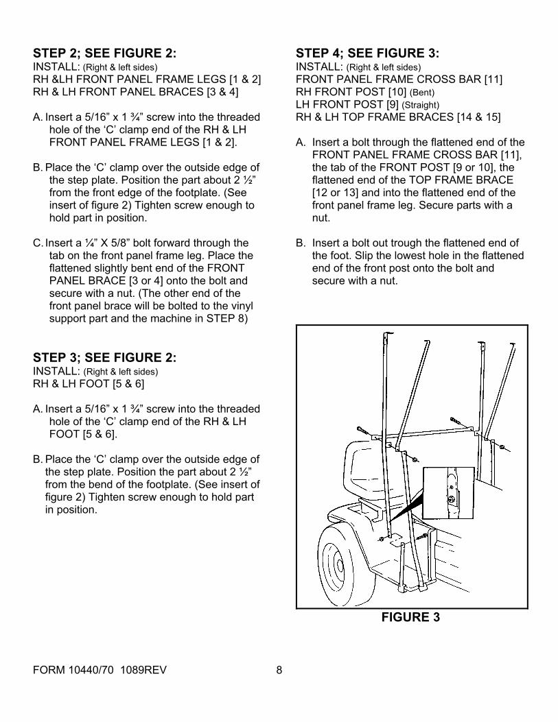
STEP 2; SEE FIGURE 2: STEP 4; SEE FIGURE 3: INSTALL: (Right & left sides) INSTALL: (Right & left sides) RH &LH FRONT PANEL FRAME LEGS [1 & 2] FRONT PANEL FRAME CROSS BAR [11] RH & LH FRONT PANEL BRACES [3 & 4] RH FRONT POST [10] (Bent) LH FRONT POST [9] (Straight) A. Insert a 5/16” x 1 ¾” screw into the threaded
hole of the ‘C’ clamp end of the RH & LH FRONT PANEL FRAME LEGS [1 & 2].
RH & LH TOP FRAME BRACES [14 & 15] A. Insert a bolt through the flattened end of the
FRONT PANEL FRAME CROSS BAR [11], the tab of the FRONT POST [9 or 10], the flattened end of the TOP FRAME BRACE [12 or 13] and into the flattened end of the front panel frame leg. Secure parts with a nut.
B. Place the ‘C’ clamp over the outside edge of
the step plate. Position the part about 2 ½” from the front edge of the footplate. (See insert of figure 2) Tighten screw enough to hold part in position.
C. Insert a ¼” X 5/8” bolt forward through the
tab on the front panel frame leg. Place the flattened slightly bent end of the FRONT PANEL BRACE [3 or 4] onto the bolt and secure with a nut. (The other end of the front panel brace will be bolted to the vinyl support part and the machine in STEP 8)
B. Insert a bolt out trough the flattened end of the foot. Slip the lowest hole in the flattened end of the front post onto the bolt and secure with a nut.
STEP 3; SEE FIGURE 2: INSTALL: (Right & left sides) RH & LH FOOT [5 & 6] A. Insert a 5/16” x 1 ¾” screw into the threaded
hole of the ‘C’ clamp end of the RH & LH FOOT [5 & 6].
B. Place the ‘C’ clamp over the outside edge of
the step plate. Position the part about 2 ½” from the bend of the footplate. (See insert of figure 2) Tighten screw enough to hold part in position.
FIGURE 3
FORM 10440/70 1089REV 8
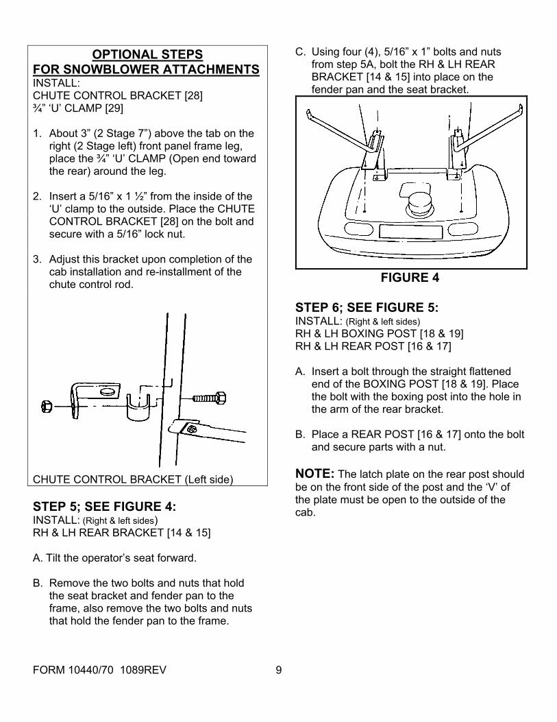
C. Using four (4), 5/16” x 1” bolts and nuts
from step 5A, bolt the RH & LH REAR BRACKET [14 & 15] into place on the fender pan and the seat bracket.
OPTIONAL STEPS FOR SNOWBLOWER ATTACHMENTS INSTALL: CHUTE CONTROL BRACKET [28]
¾” ‘U’ CLAMP [29] 1. About 3” (2 Stage 7”) above the tab on the
right (2 Stage left) front panel frame leg, place the ¾” ‘U’ CLAMP (Open end toward the rear) around the leg.
2. Insert a 5/16” x 1 ½” from the inside of the
‘U’ clamp to the outside. Place the CHUTE CONTROL BRACKET [28] on the bolt and secure with a 5/16” lock nut.
3. Adjust this bracket upon completion of the
cab installation and re-installment of the chute control rod. FIGURE 4
STEP 6; SEE FIGURE 5:
CHUTE CONTROL BRACKET (Left side)
INSTALL: (Right & left sides) RH & LH BOXING POST [18 & 19] RH & LH REAR POST [16 & 17] A. Insert a bolt through the straight flattened
end of the BOXING POST [18 & 19]. Place the bolt with the boxing post into the hole in the arm of the rear bracket.
B. Place a REAR POST [16 & 17] onto the bolt
and secure parts with a nut. NOTE: The latch plate on the rear post should be on the front side of the post and the ‘V’ of the plate must be open to the outside of the cab.
STEP 5; SEE FIGURE 4: INSTALL: (Right & left sides) RH & LH REAR BRACKET [14 & 15] A. Tilt the operator’s seat forward.
B. Remove the two bolts and nuts that hold
the seat bracket and fender pan to the frame, also remove the two bolts and nuts that hold the fender pan to the frame.
FORM 10440/70 1089REV 9
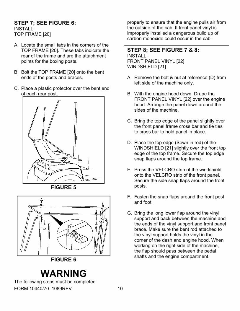
STEP 7; SEE FIGURE 6: INSTALL: TOP FRAME [20] A. Locate the small tabs in the corners of the
TOP FRAME [20]. These tabs indicate the rear of the frame and are the attachment points for the boxing posts.
B. Bolt the TOP FRAME [20] onto the bent
ends of the posts and braces. C. Place a plastic protector over the bent end
of each rear post.
FIGURE 5
FIGURE 6
WARNING The following steps must be completed
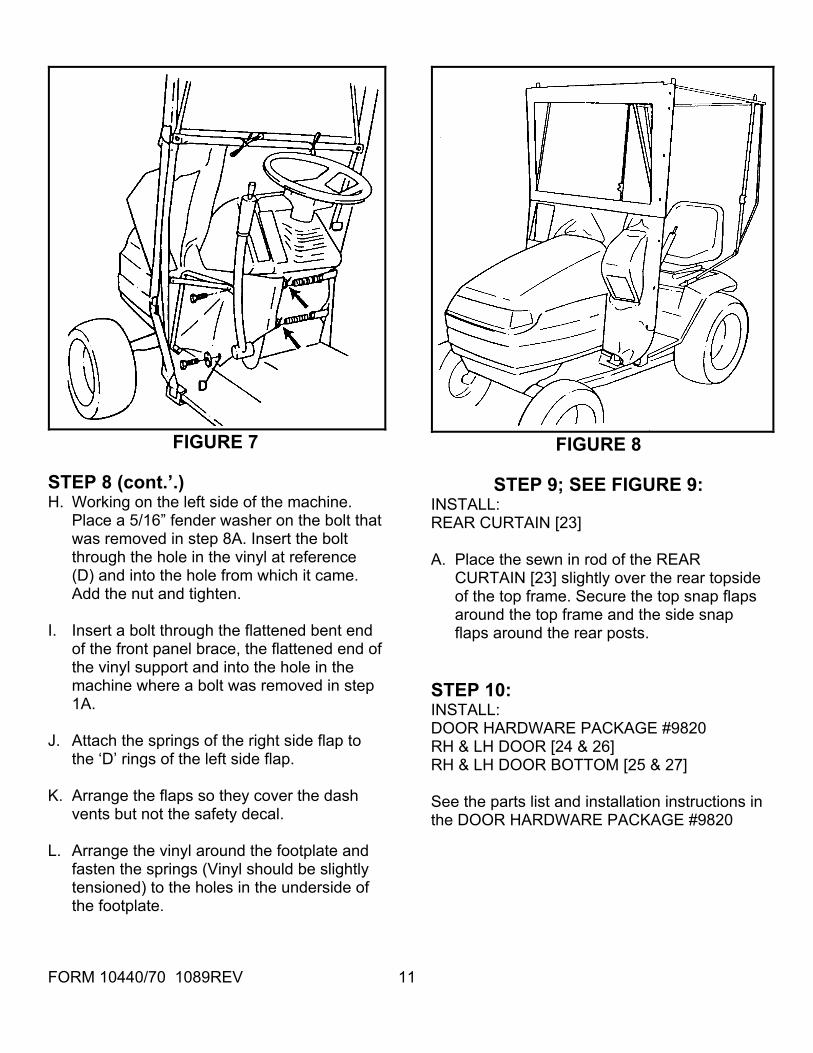
properly to ensure that the engine pulls air from the outside of the cab. If front panel vinyl is improperly installed a dangerous build up of carbon monoxide could occur in the cab. STEP 8; SEE FIGURE 7 & 8: INSTALL: FRONT PANEL VINYL [22] WINDSHIELD [21] A. Remove the bolt & nut at reference (D) from
left side of the machine only. B. With the engine hood down. Drape the
FRONT PANEL VINYL [22] over the engine hood. Arrange the panel down around the sides of the machine.
C. Bring the top edge of the panel slightly over
the front panel frame cross bar and tie ties to cross bar to hold panel in place.
D. Place the top edge (Sewn in rod) of the
WINDSHIELD [21] slightly over the front top edge of the top frame. Secure the top edge snap flaps around the top frame.
E. Press the VELCRO strip of the windshield
onto the VELCRO strip of the front panel. Secure the side snap flaps around the front posts.
F. Fasten the snap flaps around the front post
and foot. G. Bring the long lower flap around the vinyl
support and back between the machine and the ends of the vinyl support and front panel brace. Make sure the bent rod attached to the vinyl support holds the vinyl in the corner of the dash and engine hood. When working on the right side of the machine, the flap should pass between the pedal shafts and the engine compartment.
FORM 10440/70 1089REV 10
FIGURE 7 FIGURE 8
STEP 8 (cont.’.) STEP 9; SEE FIGURE 9: H. Working on the left side of the machine.
Place a 5/16” fender washer on the bolt that was removed in step 8A. Insert the bolt through the hole in the vinyl at reference (D) and into the hole from which it came. Add the nut and tighten.
INSTALL: REAR CURTAIN [23] A. Place the sewn in rod of the REAR
CURTAIN [23] slightly over the rear topside of the top frame. Secure the top snap flaps around the top frame and the side snap flaps around the rear posts.
I. Insert a bolt through the flattened bent end
of the front panel brace, the flattened end of the vinyl support and into the hole in the machine where a bolt was removed in step 1A.
STEP 10: INSTALL:
DOOR HARDWARE PACKAGE #9820 J. Attach the springs of the right side flap to
the ‘D’ rings of the left side flap. RH & LH DOOR [24 & 26] RH & LH DOOR BOTTOM [25 & 27]
K. Arrange the flaps so they cover the dash
vents but not the safety decal. See the parts list and installation instructions in the DOOR HARDWARE PACKAGE #9820
L. Arrange the vinyl around the footplate and
fasten the springs (Vinyl should be slightly tensioned) to the holes in the underside of the footplate.
FORM 10440/70 1089REV 11
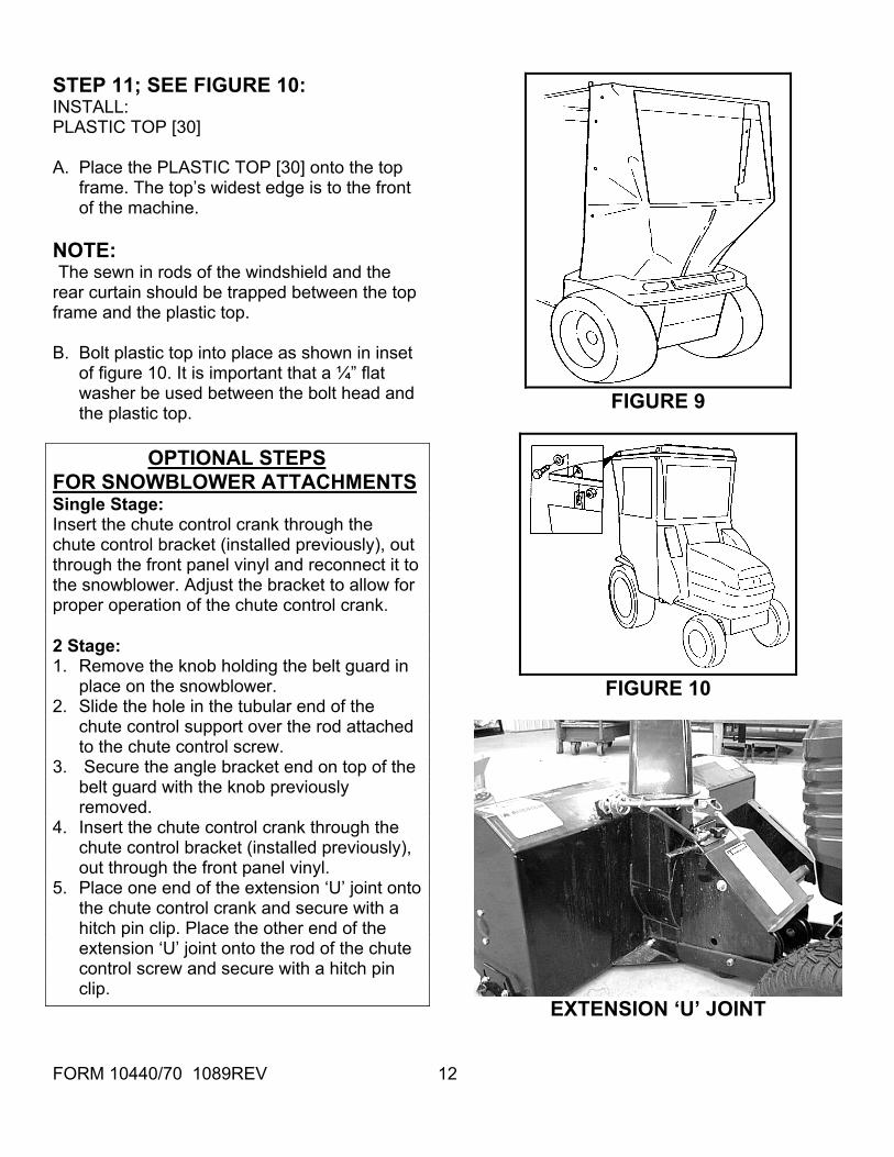
STEP 11; SEE FIGURE 10:
INSTALL: PLASTIC TOP [30] A. Place the PLASTIC TOP [30] onto the top
frame. The top’s widest edge is to the front of the machine.
NOTE: The sewn in rods of the windshield and the rear curtain should be trapped between the top frame and the plastic top. B. Bolt plastic top into place as shown in inset
of figure 10. It is important that a ¼” flat washer be used between the bolt head and the plastic top. FIGURE 9
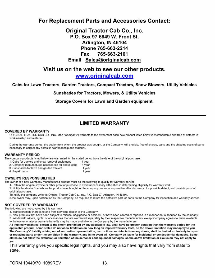
OPTIONAL STEPS FOR SNOWBLOWER ATTACHMENTS Single Stage: Insert the chute control crank through the chute control bracket (installed previously), out through the front panel vinyl and reconnect it to the snowblower. Adjust the bracket to allow for proper operation of the chute control crank. 2 Stage: 1. Remove the knob holding the belt guard in
place on the snowblower. FIGURE 10 2. Slide the hole in the tubular end of the
chute control support over the rod attached to the chute control screw.
3. Secure the angle bracket end on top of the belt guard with the knob previously removed.
4. Insert the chute control crank through the chute control bracket (installed previously), out through the front panel vinyl.
5. Place one end of the extension ‘U’ joint onto the chute control crank and secure with a hitch pin clip. Place the other end of the extension ‘U’ joint onto the rod of the chute control screw and secure with a hitch pin clip.
EXTENSION ‘U’ JOINT
FORM 10440/70 1089REV 12
FORM 10440/70 1089REV 13
For Replacement Parts and Accessories Contact:
Original Tractor Cab Co., Inc. P.O. Box 97 6849 W. Front St.
Arlington, IN 46104 Phone 765-663-2214 Fax 765-663-2101
Sunshades for Tractors, Mowers, & Utility Vehicles
Storage Covers for Lawn and Garden equipment.
LIMITED WARRANTY
COVERED BY WARRANTY ORIGINAL TRACTOR CAB CO., INC., (the "Company") warrants to the owner that each new product listed below is merchantable and free of defects in workmanship and material. During the warranty period, the dealer from whom the product was bought, or the Company, will provide, free of charge, parts and the shipping costs of parts necessary to correct any defect in workmanship and material.
WARRANTY PERIOD The company products listed below are warranted for the stated period from the date of the original purchase: 1. Cabs for tractors and snow removal equipment 1 year 2. Company manufactured accessories for above cabs 1 year 3. Sunshades for lawn and garden tractors 1 year 4. Repair parts 1 year OWNER'S RESPONSIBILITIES The owner of a new Company manufactured product must do the following to qualify for warranty service:
1. Retain the original invoice or other proof of purchase to avoid unnecessary difficulties in determining eligibility for warranty work. 2. Notify the dealer from whom the product was bought, or the company, as soon as possible after discovery of a possible defect, and provide proof of original purchase. To notify the company write to: Original Tractor Cab Co., Inc., P.O. Box 97, Arlington, IN 46104. 3.the owner may, upon notification by the Company, be required to return the defective part, or parts, to the Company for inspection and warranty service.
NOT COVERED BY WARRANTY The following are not covered by this warranty:
1. Transportation charges to and from servicing dealer or the Company; 2. New products that have been subject to misuse, negligence or accident, or have been altered or repaired in a manner not authorized by the company; 3. Windshield wipers, lights, or accessories that are warranted separately by their respective manufacturers, except Company agrees to make available to the owner whatever warranty benefits may be made available to the Company by the manufacturers. All implied warranties, except to the extent prohibited by any applicable law, shall have no greater duration than the warranty period for the applicable product, some states do not allow limitation on how long an implied warranty lasts, so the above limitation may not apply to you. The Company’s' liability arising out of warranties representation, instructions, or defects from any abuse, shall be limited exclusively to repair or replacing parts under the condition in the warranty, and in no event will Company be liable for incidental or consequential damages. Some states do not allow the exclusion or limitation of incidental or consequential damages, so the above limitation or exclusion may not apply to you. This warranty gives you specific legal rights, and you may also have rights that vary from state to state.