This chapter provides a quick review of the operatingprinciples of a four-stroke-cycle, piston engine. Theinteraction of basic engine components are discussed.Related systems—cooling, lubrication, fuel, computercontrol, and other systems—are explained. This reviewwill prepare you for later text chapters that discuss thesetopics in much more detail.
This chapter uses words and illustrations to constructa basic, one-cylinder engine. You will see how each part isinstalled in the basic engine and learn how that partperforms an important function. Then, near the end of thechapter, the systems that supplement engine operation andprotect the engine from damage are reviewed.
If you have completed an introductory course thatcovered engine operation, you should still read throughthis chapter to refresh your memory. If you are not familiarwith the operation of an engine, study this chapter care-fully. This will let you catch up with the students that havealready had some training in engines.
Automotive Engine
An engine is the source of power for moving the vehi-cle and operating the other systems. Sometimes termed thepower plant, it burns a fuel (usually gasoline or diesel fuel)to produce heat, expansion of gasses, pressure, and result-ing part movement.
Since a vehicle’s engine burns fuel inside of itself, it istermed an internal combustion engine. As you will learn,the arrangement of an engine’s parts allows it to harnessthe energy of the burning fuel.
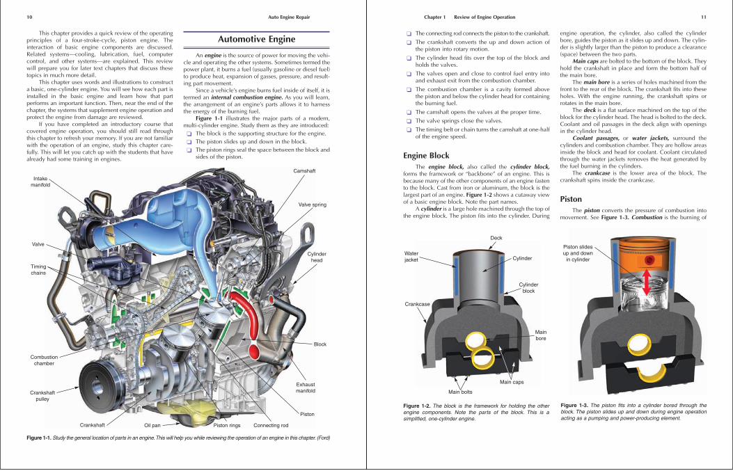
Figure 1-1 illustrates the major parts of a modern,multi-cylinder engine. Study them as they are introduced:
� The block is the supporting structure for the engine.
� The piston slides up and down in the block.
� The piston rings seal the space between the block andsides of the piston.
10 Auto Engine Repair
Intakemanifold
Valve
Timingchains
Combustionchamber
Crankshaftpulley
Crankshaft Oil pan Piston rings Connecting rod
Piston
Exhaustmanifold
Block
Cylinderhead
Valve spring
Camshaft
Figure 1-1. Study the general location of parts in an engine.This will help you while reviewing the operation of an engine in this chapter. (Ford)
� The connecting rod connects the piston to the crankshaft.
� The crankshaft converts the up and down action ofthe piston into rotary motion.
� The cylinder head fits over the top of the block andholds the valves.
� The valves open and close to control fuel entry intoand exhaust exit from the combustion chamber.
� The combustion chamber is a cavity formed abovethe piston and below the cylinder head for containingthe burning fuel.
� The camshaft opens the valves at the proper time.
� The valve springs close the valves.
� The timing belt or chain turns the camshaft at one-halfof the engine speed.
Engine BlockThe engine block, also called the cylinder block,
forms the framework or “backbone” of an engine. This isbecause many of the other components of an engine fastento the block. Cast from iron or aluminum, the block is thelargest part of an engine. Figure 1-2 shows a cutaway viewof a basic engine block. Note the part names.
A cylinder is a large hole machined through the top ofthe engine block. The piston fits into the cylinder. During
engine operation, the cylinder, also called the cylinderbore, guides the piston as it slides up and down. The cylin-der is slightly larger than the piston to produce a clearance(space) between the two parts.
Main caps are bolted to the bottom of the block. Theyhold the crankshaft in place and form the bottom half ofthe main bore.
The main bore is a series of holes machined from thefront to the rear of the block. The crankshaft fits into theseholes. With the engine running, the crankshaft spins orrotates in the main bore.
The deck is a flat surface machined on the top of theblock for the cylinder head. The head is bolted to the deck.Coolant and oil passages in the deck align with openingsin the cylinder head.
Coolant passages, or water jackets, surround thecylinders and combustion chamber. They are hollow areasinside the block and head for coolant. Coolant circulatedthrough the water jackets removes the heat generated bythe fuel burning in the cylinders.
The crankcase is the lower area of the block. Thecrankshaft spins inside the crankcase.
PistonThe piston converts the pressure of combustion into
movement. See Figure 1-3. Combustion is the burning of
Chapter 1 Review of Engine Operation 11
Main caps
Main bolts
Mainbore
Crankcase
Cylinder
Deck
Waterjacket
Cylinderblock
Figure 1-2. The block is the framework for holding the otherengine components. Note the parts of the block. This is asimplified, one-cylinder engine.
Piston slidesup and down
in cylinder
Figure 1-3. The piston fits into a cylinder bored through theblock. The piston slides up and down during engine operationacting as a pumping and power-producing element.
fuel, which results in expanding gas inside the cylinder.The piston transfers the pressure of combustion to thepiston pin, connecting rod, and crankshaft. It also holdsthe piston rings and piston pin.
During engine operation, the piston slides up anddown in the cylinder at tremendous speeds. At a vehiclespeed of about 55 mph (88 km/h), the piston can accel-erate from zero to 60 miles an hour and then back tozero in one movement from top to bottom in thecylinder. This places tremendous stress on the piston andits related parts.
Piston RingsThe piston rings fit into grooves machined into the
sides of the piston. These rings keep combustion pressurefrom entering the crankcase and engine oil from enteringthe combustion chamber. Look at Figure 1-4.
The compression rings seal the clearance betweenthe block and piston. They are normally the two upperpiston rings. Their job is to contain the pressure formed inthe combustion chamber, Figure 1-5. Without compres-sion rings, pressure would blow past the outside diameterof the piston and into the lower area of the engine block.
The oil ring fits into the lowest groove in the piston. Itis designed to scrape excess oil from the cylinder wall tokeep it from being burned in the combustion chamber,Figure 1-6. If oil enters the area above the piston andburns, blue smoke blows out of the tailpipe.
Piston PinA piston pin, also called a wrist pin, allows the con-
necting rod to swing back and forth inside the piston. Thepin fits through a hole machined in the piston and througha hole in the upper end of the connecting rod. Refer toFigure 1-7.
12 Auto Engine Repair
Pistonclearance
Pistonclearance
Pistondiameter
Compressionrings
Oil ring
Piston pin
Figure 1-4. The clearance between the piston and cylinderallows the piston to move freely in the cylinder. Rings seal theclearance.
Combustionpressure
Compressionring
Ringtension
CylinderwallPiston
Figure 1-5. The compression rings use combustion pressure tohelp seal against the cylinder wall. This keeps pressure in thecombustion chamber and out of the crankcase.
Cylinder wall
Piston
Oil controlring
Escapingoil
Oil to crankcaseOil film
Ringgroove
Figure 1-6. Oil rings act as a scraper to keep oil out of the com-bustion chamber. (Deere & Co.)
Pistonhead
Piston
Ringlands
Pistonpin
Pistonpin bore
Connectingrod
Swinging action
Figure 1-7. The piston pin fits into a hole bored in the piston.The pin attaches the piston to the connecting rod.
Connecting RodThe connecting rod transfers the force of the piston to
the crankshaft. It is fastened to the piston pin at the top andthe crankshaft at the bottom. It also causes piston move-ment on nonpower-producing events (up and down pistonmovements). See Figure 1-8.
The small, top end of the connecting rod has a holemachined in it for the piston pin. The top of the rodextends inside of the piston.
The big, bottom end of the connecting rod fits aroundthe crankshaft journal. It has a removable cap that allowsthe installation and removal of the rod-piston assembly.Special rod bolts and nuts hold the cap in place.
As discussed in later chapters, bushings are normallyinstalled in the small end of the rod. Rod bearings areinstalled in the big end of the connecting rod.
CrankshaftThe crankshaft converts the up and down (reciprocat-
ing) movement of the connecting rod and piston into rotarymotion. The rotary motion is used to power gears, chains,belts, and the drive train.
The crankshaft fits into the main bore of the engineblock, as shown in Figure 1-9. It mounts on the main bear-ings and is free to spin inside the block. The connectingrods are attached to the crankshaft journals. Figure 1-10
Chapter 1 Review of Engine Operation 13
Big endfor rodbearing
Rod nut
Rod cap
Rod bolt
Connectingrod I-beam
Small endPiston
pin
Figure 1-8. The connecting rod links the piston and crankshafttogether.The large end has a removable cap that allows the rodto be bolted around the crankshaft journal. The small end has ahole for the piston pin.
Mainjournals
Snout
Counterweight
Flywheelflange
Rodjournal
Figure 1-9. The crankshaft takes the reciprocating motion ofthe piston and produces rotary motion for vehicle’s drive trainand accessory system.
Piston attop dead
center
Piston atbottom dead
center
Rod andits crankshaft
journal up
Rod and itscrankshaft
journal down
Figure 1-10. Note how the crankshaft changes the recipro-cating motion of the piston into rotary motion.
shows how the crankshaft changes the reciprocating (upand down) motion of the piston and connecting rod into arotary motion.
The engine flywheel is a very heavy, round diskmounted to the back of the crankshaft. It helps to keep thecrankshaft spinning between power strokes and smoothengine operation. It also holds a large gear used by thestarter.
TDC and BDCThe abbreviation TDC stands for top dead center. This
is the point of travel where the piston is at its highest pointin the cylinder. The abbreviation BDC stands for bottomdead center. This is the point of travel where the piston isat its lowest point in the cylinder. Refer to Figure 1-11.
Cylinder HeadThe cylinder head is bolted to the top of the block
deck to enclose the top of the cylinders and form the topof the combustion chamber, Figure 1-12. Like the block,the cylinder head contains water jackets for cooling andoil passages for lubricating moving parts on or in thecylinder head.
Valve guides are machined through the top of thehead for the valves. The valves slide up and down in theseguides.
Cylinder head ports are passages for the air-fuelmixture to enter the combustion chamber and for exhaustgasses to flow out of the engine. These are located in thecylinder head.
Valve seats are machined in the opening where theports enter the combustion chamber. The valves close againstthe seats to make a leakproof seal at high temperatures.
Engine ValvesEngine valves control the flow into and out of the
engine cylinder or combustion chamber. They fit into thecylinder head, operate inside the valve guides, and closeon the valve seats. Valve springs fit over the top end of thevalves to keep the valves in a normally closed position,Figure 1-13.
Figure 1-14 shows how a valve opens and closes theports in the cylinder head. When the valve slides down,the valve head moves away from the valve seat and theport is opened. When the valve slides up, the valve headmoves toward the valve seat until the valve face makescontact with the valve seat. This seals the combustionchamber from the port.
14 Auto Engine Repair
Top deadcenter(TDC)
Piston
Crankshaft
One-halfrevolution
180°
One stroke
TDC
BDC
Connectingrod
Bottomdead center
(BDC)
Figure 1-11. TDC is when the piston is at the top of its stroke.BDC is when the piston is at the bottom of its stroke. One strokeis the piston movement from TDC to BDC or vice versa. (Ford)
Cylinder headValve guides
Waterjacket
Exhaustport
Exhaustvalve seat
Intakevalve seat
Intakeport
Figure 1-12. The cylinder head is bolted to the top of the block.It forms a cover over the cylinder. The head also holds thevalves that control flow into and out of the cylinder.
There are two types of valves—intake and exhaust.The intake valve is the larger valve and it allows a fuelcharge to flow into the cylinder. The exhaust valve is thesmaller valve and it opens to let burned gasses (exhaust)out of the cylinder. Figure 1-15 shows how the air-fuelmixture flows through the intake port, past the valve, andinto the combustion chamber when the valve is open.
Four-Stroke Cycle
The four-stroke cycle needs four up or down pistonmovements, or strokes, to produce one complete cycle.Every two up and two down strokes of the piston results
in one power-producing cycle. Two complete revolutionsof the crankshaft are needed to complete one four-strokecycle. Automotive engines, both gas and diesel, arefour-stroke-cycle engines.
The four strokes are intake, compression, power,and exhaust. With the engine operating, these strokeshappen over and over very rapidly. At idle, an enginemight be running at 800 revolutions per minute (rpm),which means the crankshaft rotates 800 times in oneminute. Since it takes two complete revolutions of thecrankshaft to complete a four-stroke cycle, an enginecompletes 400 four-stroke cycles per minute at idle. Inother words, the piston must slide up 800 times anddown 800 times per minute. You can imagine how fastthese events are happening at highway speeds!
Intake StrokeA gasoline engine’s intake stroke draws air and fuel
into the combustion chamber. Figure 1-16A shows thebasic action during the intake stroke. Study the position ofthe valves and movement of the piston. The piston slidesdown to form a vacuum (low pressure area). The intakevalve is open and the exhaust valve is closed. Atmosphericpressure (outside air pressure) pushes the air-fuel chargeinto the vacuum in the cylinder. This fills the cylinder witha burnable mixture of fuel and air.
Compression StrokeThe compression stroke squeezes the air-fuel mixture
to make it more combustible. See Figure 1-16B. Both theintake and exhaust valves are closed. The piston slides upand compresses the mixture into the small area in the com-bustion chamber.
Chapter 1 Review of Engine Operation 15
Intakevalve
Intakeport
Exhaustvalve
Exhaustport
Valve springs
Figure 1-13. Valves fit into guides in the cylinder head. Valvesprings hold the valves closed. The valves seal against valveseats in the head to close off ports from the combustion chamber.
Cylinderhead
Valve guide
Valveseat
Valveface
Valvehead
Margin
Port
Figure 1-14. Study the valve action. When the valve slidesopen, the valve face is lifted off of the valve seat.This opens theport to the combustion chamber and gasses are free to enter orexit the cylinder.
Air-fuelmixture
Port incylinder head
Intakevalve open
Figure 1-15. Note the action as the intake valve opens.Downward movement of the piston forms a vacuum in thecylinder. Atmospheric pressure pushes the air-fuel charge intothe cylinder. (Ford)
16 Auto Engine Repair
The piston slides down with the intake valve open and the exhaust valve closed. The air-fuel charge is pulled into the cylinder.
Both valves are closed and the piston slides up. This compresses the air-fuel charge and prepares it for combustion.
The spark plug fires and the fuel begins to burn. The heat of combustion causes expansion of the gasses and creates pressure. This pushes the piston down with tremendous force to spin the crankshaft.
The piston slides up with the intake valve closed and the exhaust valve open. This pushes the exhaust gasses out of the cylinder so a fresh charge can enter.
A—Intake Stroke B—Compression Stroke
C—Power Stroke D—Exhaust Stroke
Air-fuel mixturepulled into
cylinder
Intake valveopen
Piston androd moving
down
Intake valveclosed
Pressure formedon fuel charge
Exhaustvalve
closed
Piston androd moving up
Burnedgasses
pushed fromcylinder
Exhaust valveopen
Pistonand rod
moving up
Intake valvedclosed
Sparkplug fires
Exhaust valveclosed
Air-fuel mixtureburns, expands,
and formspressure
Piston androd pusheddown to turncrankshaft
Intakevalve
closed
Exhaustvalve
closed
Figure 1-16. Review the four-stroke cycle. You must be able to visualize these events to be a competent engine technician.
For proper combustion (burning), it is very importantthat the valves, rings, and other components do not allowpressure leakage out of the combustion chamber. Leakageduring the compression stroke may prevent the mixturefrom igniting and burning on the power stroke.
Power StrokeThe air-fuel mixture is ignited and burned during the
power stroke to produce gas expansion, pressure, and apowerful downward piston movement. See Figure 1-16C.Both valves are still closed. The spark plug fires and thefuel mixture begins to burn.
As the mixture burns, it expands and builds pressure inthe combustion chamber. Since the piston is the only partthat can move, it is thrust downward with several tons offorce. This downward thrust pushes on the connecting rodand crankshaft forcing the crankshaft to turn. The powerstroke is the only stroke that does not consume (use) energy.
Exhaust StrokeThe exhaust stroke pushes the burned gasses out of
the cylinder and into the vehicle’s exhaust system. SeeFigure 1-16D. The intake valve remains closed, but theexhaust valve is open. Since the piston is now moving up,the burned gasses are pushed out of the exhaust port toready the cylinder for another intake stroke.
Valve Train
The valve train operates the engine valves. It timesvalve opening and closing to produce the four-strokecycle. Basic valve train parts are shown in Figure 1-17.
The camshaft opens the valves and allows the valvesprings to close the valves at the proper times. Thecamshaft has a series of lobes (egg-shaped bumps) that acton the valves or valve train to slide the valve down in itsguide. See Figure 1-18.
Chapter 1 Review of Engine Operation 17
Rocker armpushesdown
Valvepushedoff seat
Cam lobetouches
lifter
Rocker arm pushedup by spring
Spring
Valve closedon seat
Lifter(tappet)
Lobe awayfrom lifter
Push rod
Valve open Valve closed
Pivot point
Figure 1-17. The camshaft operates the valve train. When the cam lobe rotates into a lifter, the valve is opened. When a lobe movesout of a lifter, the valve spring closes the valve. (Ford)
Camshaft
Cam lobes
Figure 1-18. The lobes on the camshaft act on the valves orvalve train to open and close the valves. As shown here, thecamshaft fits into the cylinder head on many engines. This letsit operate directly on valves without using push rods.
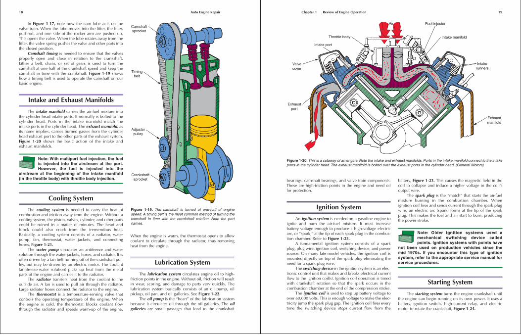
In Figure 1-17, note how the cam lobe acts on thevalve train. When the lobe moves into the lifter, the lifter,pushrod, and one side of the rocker arm are pushed up.This opens the valve. When the lobe rotates away from thelifter, the valve spring pushes the valve and other parts intothe closed position.
Camshaft timing is needed to ensure that the valvesproperly open and close in relation to the crankshaft.Either a belt, chain, or set of gears is used to turn thecamshaft at one-half of the crankshaft speed and keep thecamshaft in time with the crankshaft. Figure 1-19 showshow a timing belt is used to operate the camshaft on ourbasic engine.
Intake and Exhaust Manifolds
The intake manifold carries the air-fuel mixture intothe cylinder head intake ports. It normally is bolted to thecylinder head. Ports in the intake manifold match theintake ports in the cylinder head. The exhaust manifold, asits name implies, carries burned gasses from the cylinderhead exhaust port to the other parts of the exhaust system.Figure 1-20 shows the basic action of the intake andexhaust manifolds.
Note: With multiport fuel injection, the fuelis injected into the airstream at the port.However, the fuel is injected into the
airstream at the beginning of the intake manifold(in the throttle body) with throttle body injection.
Cooling System
The cooling system is needed to carry the heat ofcombustion and friction away from the engine. Without acooling system, the piston, valves, cylinder, and other partscould be ruined in a matter of minutes. The head andblock could also crack from the tremendous heat.Basically, a cooling system consists of a radiator, waterpump, fan, thermostat, water jackets, and connectinghoses, Figure 1-21.
The water pump circulates an antifreeze and watersolution through the water jackets, hoses, and radiator. It isoften driven by a fan belt running off of the crankshaft pul-ley, but may be driven by an electric motor. The coolant(antifreeze-water solution) picks up heat from the metalparts of the engine and carries it to the radiator.
The radiator transfers heat from the coolant to theoutside air. A fan is used to pull air through the radiator.Large radiator hoses connect the radiator to the engine.
The thermostat is a temperature-sensing valve thatcontrols the operating temperature of the engine. Whenthe engine is cold, the thermostat blocks coolant flowthrough the radiator and speeds warm-up of the engine.
When the engine is warm, the thermostat opens to allowcoolant to circulate through the radiator, thus removingheat from the engine.
Lubrication System
The lubrication system circulates engine oil to high-friction points in the engine. Without oil, friction will resultin wear, scoring, and damage to parts very quickly. Thelubrication system basically consists of an oil pump, oilpickup, oil pan, and oil galleries. See Figure 1-22.
The oil pump is the “heart” of the lubrication systembecause it circulates oil through the oil galleries. The oilgalleries are small passages that lead to the crankshaft
18 Auto Engine Repair
Camshaftsprocket
Timingbelt
Adjusterpulley
Crankshaftsprocket
Figure 1-19. The camshaft is turned at one-half of enginespeed. A timing belt is the most common method of turning thecamshaft in time with the crankshaft rotation. Note the partnames.
bearings, camshaft bearings, and valve train components.These are high-friction points in the engine and need oilfor protection.
Ignition System
An ignition system is needed on a gasoline engine toignite and burn the air-fuel mixture. It must increasebattery voltage enough to produce a high-voltage electricarc, or “spark,” at the tip of each spark plug in the combus-tion chamber. Refer to Figure 1-23.
A fundamental ignition system consists of a sparkplug, plug wire, ignition coil, switching device, and powersource. On many late-model vehicles, the ignition coil ismounted directly on top of the spark plug eliminating theneed for a spark plug wire.
The switching device in the ignition system is an elec-tronic control unit that makes and breaks electrical currentflow to the ignition coil(s). Ignition coil operation is timedwith crankshaft rotation so that the spark occurs in thecombustion chamber at the end of the compression stroke.
The ignition coil is used to step up battery voltage toover 60,000 volts. This is enough voltage to make the elec-tricity jump the spark plug gap. The ignition coil fires everytime the switching device stops current flow from the
battery, Figure 1-23. This causes the magnetic field in thecoil to collapse and induce a higher voltage in the coil’soutput wire.
The spark plug is the “match” that starts the air-fuelmixture burning in the combustion chamber. Whenignition coil fires and sends current through the spark plugwire, an electric arc (spark) forms at the tip of the sparkplug. This makes the fuel and air start to burn, producingthe power stroke.
Note: Older ignition systems used amechanical switching device calledpoints. Ignition systems with points have
not been used on production vehicles since themid 1970s. If you encounter this type of ignitionsystem, refer to the appropriate service manual forservice procedures.
Starting System
The starting system turns the engine crankshaft untilthe engine can begin running on its own power. It uses abattery, ignition switch, high-current relay, and electricmotor to rotate the crankshaft, Figure 1-24.
Chapter 1 Review of Engine Operation 19
Throttle body
Intake port
Valvecover
Exhaustport
Exhaustmanifold
Intakerunners
Intake manifold
Fuel injectorAir
Figure 1-20. This is a cutaway of an engine. Note the intake and exhaust manifolds. Ports in the intake manifold connect to the intakeports in the cylinder head. The exhaust manifold is bolted over the exhaust ports in the cylinder head. (General Motors)
The battery stores chemical energy that can bechanged into electrical energy. When the driver turns igni-tion switch (start switch), the solenoid (high-current relay)sends battery current to the starter motor. The startermotor has a small gear that engages a large gear on thecrankshaft flywheel. The motor has enough torque (turningforce) to spin the flywheel, and thus the crankshaft, untilthe engine starts and runs. Then, the driver releases theignition key and deactivates the starting system.
20 Auto Engine Repair
Hot coolant
Waterpump
Enginewaterjacket
Crankshaft pulley
Fan belt
Cooledcoolant
Airflow toremove heatfrom coolant
Fan
Radiator
Figure 1-21. A cooling system is needed to remove heat fromthe engine and prevent severe engine damage. Water jacketsallow coolant to flow around the cylinders and through thecylinder head. A water pump circulates coolant through thesystem. The radiator dissipates heat into the outside air. A fanpulls air through the radiator. (DaimlerChrysler)
Oildipstick
Oil to crankand camshaft
Oil pump
Oil gallery
Oil filter
Oil tovalve train
Oil pan
Figure 1-22. The lubrication system prevents excess frictionthat may damage the engine. Note the part names.(DaimlerChrysler)
Combustion
Sparkplug
Spark plugwire
Ignition coilBattery
Electroniccontrol unitor switching
device
Speed sensingdevice or
pickup coil
Trigger wheel
Figure 1-23. The ignition system is used on a gasoline engineto ignite the fuel in the combustion chamber. A coil produceshigh voltage for the spark plug. When the switching devicebreaks the flow of current to the coil, the coil and spark plug fireto ignite the fuel.
Main fuse
Wiring harness
Flywheelring gear
Starter solenoid
Starter cable
Starter motor Ignitionswitch
Positivebatterycable
Negative orgroundcable
Figure 1-24. The starting system rotates the crankshaft until theengine starts. A powerful electric starter motor has a gear thatmeshes with the gear on the engine flywheel. A solenoid makesthe electrical connection between the battery and the startermotor when the ignition key is turned to the start position. (Honda)
Charging System
The charging system is needed to recharge (re-energize)the battery after starting system or other electrical systemoperation. The battery can become discharged (run down)after only a few minutes of starter motor operation. Thecharging system also provides all of the vehicle’s electricalneeds while the engine is running. Basically, the chargingsystem consists of the alternator and a voltage regulator.Look at Figure 1-25.
The alternator produces the electricity to recharge thebattery. It is driven by a belt from the engine crankshaftpulley. The alternator sends current through the battery toreactivate the chemicals in the battery. This again preparesthe battery for starting or other electrical loads.
The voltage regulator controls the electrical output ofthe alternator. It ensures that about 14.5 volts are producedby the alternator. Current then flows back into the battery,since battery voltage is only about 12.5 volts.
Fuel System
The fuel system must meter the right amount of fuel(usually gasoline or diesel oil) into the engine for efficientcombustion under different conditions. At low speeds, itmust meter a small amount of fuel into the airstream. Asengine speed and load increase, the fuel system mustmeter more fuel into the airstream. The fuel system mustalso alter the fuel metering with changes in engine temper-ature and other variables.
There are two basic types of automotive fuel systemsin current use—gasoline injection and diesel injection. Athird type of fuel system—carburetion—has not beencommonly used since the mid 1980s.
Gasoline Injection SystemA gasoline injection system uses fuel pump pressure
to spray fuel into the engine intake manifold, usually nearthe cylinder head’s intake port. A basic system is picturedin Figure 1-26.
An electric fuel pump forces fuel from the fuel tank tothe fuel injector. A constant pressure is maintained at theinjector. The fuel injector is simply an electrically-operatedfuel valve. When energized by the control module, itopens and squirts fuel into the intake manifold or the com-bustion chamber. When not energized, it closes and pre-vents fuel entry into the engine.
Modern gasoline injection systems open the injectorwhen the engine intake valve opens. Then, fuel is partiallyor completely forced into the combustion chamber bypump pressure. This helps control how much fuel entersthe cylinder and also increases combustion efficiency, asyou will learn in later chapters.
A control module (computer) is used to regulate whenand how long the injector opens. It uses electrical informa-tion from various sensors to analyze the needs and operatingconditions of the engine. The engine sensors monitorvarious operating conditions, such as engine temperature,speed, load, and so on. In this way, the computer can deter-mine whether more or less fuel is needed and whether theinjector should be opened for a longer or shorter period oftime based on the current operating conditions.
A throttle valve controls airflow, engine speed, andengine power. It is connected to the accelerator pedal. Whenthe pedal is pressed, the throttle valve opens to allow more airinto the combustion chambers. In turn, the control moduleholds the injectors open for a longer period of time, allowingmore fuel into the combustion chamber. The increase in airand fuel results in an increase in engine power output.
As the accelerator pedal is released, the throttle valvecloses, reducing the amount of air allowed into thecombustion chamber. The control module, in turn, reducesthe amount of time the injectors are open, thus reducingthe amount of fuel released into the injection chamber.The decrease in air and fuel results in a decrease in enginepower output.
Diesel Injection SystemA diesel injection system forces fuel directly into the
engine’s combustion chamber, as shown in Figure 1-27.The heat resulting from highly compressed air, not an elec-tric spark plug, ignites and burns the fuel. When the intakevalve opens, a full charge of air is allowed to flow into thecylinder. Then, on the compression stroke, the air issqueezed until it is at a high temperature. As soon as thefuel is injected into the hot air, the fuel burns and expands.
A diesel injection system basically consists of aninjection pump, injector, and glow plug system. Theinjection pump is a high-pressure, mechanical pump. It ispowered by the engine and forces fuel to the dieselinjector under very-high pressure. A conventional fuelpump feeds fuel from the tank to the injection pump.
Chapter 1 Review of Engine Operation 21
Battery
Voltageregulator
Main fuse
Charging systemwiring harness
Chargeindicator
Alternator
Alternatorbelt
Figure 1-25. The charging system recharges the battery andprovides the vehicle’s electrical needs while the engine isrunning. (Honda)
The diesel injector is simply a spring-loaded valve. Itis normally closed and blocks fuel flow. However, whenthe injection pump forces fuel into the injector under highpressure, the injector opens. The fuel is sprayed directlyinto the combustion chamber or a precombustion cham-ber. This is called a direct injection system.
Note in Figure 1-27 that a diesel does not have athrottle valve or a spark plug. Engine power and speed arecontrolled by the injection pump, which is controlled by acontrol module. The more fuel injected into the combus-tion chamber, the more speed and power are produced bythe engine. As less fuel is injected into the combustionchamber, engine speed and power decrease.
A glow plug system is used to aid cold starting of adiesel engine. The glow plug is an electric heating elementthat warms the air in the combustion chamber. This helps
the air become hot enough to start combustion until theheat from engine operation can warm the incoming air.
Carburetion Fuel SystemInstead of injecting fuel into the airstream or combustion
chamber, a carburetion system uses engine vacuum (suction) topull fuel into the engine, Figure 1-28. Airflow through the carbu-retor and the vacuum created by the engine’s intake stroke drawfuel out of the carburetor’s fuel bowl. As the throttle valve isopened, more air flows through the carburetor and, thus, morefuel flows into the airstream. A low-pressure, mechanical fuelpump draws fuel from the tank and delivers it to the carburetor’sfuel bowl. The carburetion system is not currently used on late-model vehicles but is still found on small gas engines.
Figure 1-26. Gasoline injection uses pressure from an electric fuel pump to spray fuel into engine intake manifold through fuelinjectors. A throttle valve is used to control the airflow into the engine.
Only air flows past intake valveand into combustion chamber
Diesel fuelfrom tank
High-pressuremechanical pump
Fuel ignites as ittouches hot air
Injection line
Figure 1-27. Diesel injection is primarily mechanical. A mechanical injection pump forces fuel into a spring-loaded injector nozzle.Thepressure opens the injector and fuel sprays directly into combustion chamber. A diesel does not use a throttle valve or spark plug.
Computer System
A computer system is used to increase the overall effi-ciency of a vehicle. The computer, or control module, cancontrol the ignition system, fuel system, transmission ortransaxle, emission control systems, and other systems.Figure 1-29 shows a diagram of a simplified vehicle com-puter system. A modern vehicle may have several controlmodules.
To understand how a vehicle’s computer controlsystem works, think of the human body’s central nervous
system. For example, if your finger touches a hot stove, thenerves (sensors) in your hand send a signal to your brain.Your brain (control module) analyzes these signals anddecides that you are in pain. Your brain (control module)quickly activates your muscles (actuators) to pull yourhand away from the hot stove. A computer control systemworks in the same manner. It controls actions based onsensory inputs. For simplicity, a vehicle’s computer controlsystem can be divided into three subsystems: sensor,control, and actuator.
The sensor subsystem checks various operatingconditions using sensors. A sensor is a device that can
Chapter 1 Review of Engine Operation 23
Air enters filter
Carburetor
Fuel pulled intoairstream by vacuum
Throttle controls airflow and engine speed
Air-fuel mixture flowsto cylinder
Mixture ignitedby spark plug
Fuelfrom tank
Low-pressuremechanical fuel
pump
Fuel line
Figure 1-28. Carburetion systems are not used on passenger vehicles, but are still used on small gas engines. In this type of sys-tem, airflow into engine pulls fuel out of carburetor’s fuel bowl. A mechanical fuel pump fills the fuel bowl with fuel, but does not forcethe fuel into the intake manifold.
Fuel pressure regulator
Fuel pump
Fuel injectors
Control module
Knock sensor
Mass airflow sensor
Oxygen sensor
Manifold absolutepressure sensor
Intake airtemperatue sensor
Engine coolanttemperature sensor
Engine speed sensor
Throttle position sensor
Catalyst monitor
Figure 1-29. This is a simplified diagram of the sensor, control, and actuator subsystems of a computer control system for fuelinjector operation.
change its electrical signal based on a change in a condi-tion. Sensors might measure intake manifold vacuum,throttle opening, engine speed, transmission gear position,road speed, turbocharger boost pressure, and other condi-tions. The sensing system sends different electrical currentvalues back to the control module.
The control subsystem looks at the inputs from thesensors and determines what actions need to take place. Acontrol module, or computer, contains miniaturized electricalcircuits that collect, store, and analyze information. The con-trol module then provides signals to the actuator subsystem.
The actuator subsystem serves as the “hands” of thecomputer system. Based on signals from the control mod-ule, this system moves parts, opens injectors, closes thethrottle, turns on the fuel pump, and performs other tasksneeded to increase the overall efficiency of the vehicle.Electric motors, solenoids or relays, and switches are theactuators. The actuators turn on or off, open or close, orchange position based on the signals from the controlmodule. This is discussed in detail later in this textbook.
Emission Control Systems
Emission control systems are designed to reduce theamount of harmful chemicals and compounds (emissions)that enter the atmosphere from a vehicle. There are severaltypes of emission control systems:
� PCV. The positive crankcase ventilation system pullsfumes from the engine crankcase into the intake manifoldso they can be burned before entering the atmosphere.
� Evaporative emissions control. This system uses acharcoal-filled canister to collect and store gasolinefumes from the fuel tank when the engine is notrunning. Air is drawn through the canister and intothe intake manifold while the engine is running so thecollected fumes are burned.
� EGR. The exhaust gas recirculation system injectsexhaust gasses into the engine to lower combustiontemperatures and reduce one form of pollution in theengine exhaust.
� Air injection. This system forces air into the exhauststream leaving the engine to help burn any unburnedfuel that exits the combustion chamber.
� Catalytic converter. This device chemically convertsbyproducts of combustion into harmless substances.
Many of these systems work together, all reducingtheir share of harmful emissions. The computer also playsan important part in reducing pollution. It improves theefficiency of many systems.
Drive Train
The drive train uses power from the engine to turn thevehicle’s drive wheels. Drive train configurations vary, but
can generally be classified as rear-wheel drive or front-wheel drive. Figure 1-30 shows simplified drive trains.
ClutchThe clutch allows the driver to engage or disengage
the engine power from the drive train. It is mounted ontothe engine flywheel between the engine and transmissionor transaxle. A clutch is needed when the vehicle has amanual transmission. A vehicle with an automatic trans-mission does not have a clutch.
TransmissionThe transmission uses a series of gears to allow the
amount of torque going to the drive wheels to be varied. Thedriver can shift gears to change the ratio of crankshaft revo-lutions to drive wheel rotation. When first accelerating, moretorque is needed to get the vehicle moving. Then, at higherroad speeds, less torque is needed to maintain road speed.Engine speed also needs to be reduced at highway speeds.
A manual transmission is shifted by hand. Levers,cables, or rods connect the driver’s shift lever to the inter-nal parts of the transmission. An automatic transmissionuses a hydraulic (fluid pressure) system to shift gears. Atorque converter (fluid clutch) and special planetary gearsets provide automatic operation. However, the drivermust manually change the shift lever position to changefrom forward to reverse.
A transaxle is a transmission and a differential (axledrive mechanism) combined into one housing. It iscommonly used with front-wheel-drive vehicles, but mayalso be found on rear-engine, rear-wheel-drive vehicles. Atransaxle may be manual or automatic.
Drive Shaft and Drive AxleA drive shaft is used with a front-engine, rear-wheel-
drive vehicle. It connects the transmission to the differential.A drive axle connects the differential to the drive hubs
or wheels. On most rear-wheel-drive vehicles, the driveaxle is a solid steel shaft. On vehicles with a transaxle, thedrive axle is a flexible shaft extending from the transaxle tothe front wheel hubs.
Summary
This chapter reviewed the basic operation of a four-stroke-cycle, piston engine. The engine found in mostvehicles is called an internal combustion engine because itburns fuel inside of combustion chambers.
The cylinder block holds the other parts. The pistonand connecting rod transfer combustion pressure to thecrankshaft. The crankshaft converts the up and downaction of the piston into rotary motion.
24 Auto Engine Repair
The cylinder head is bolted on top of the cylinderblock. It contains the valves that control flow into and outof the cylinder. The camshaft operates the valves so thatthey open and close to correspond to piston action, pro-ducing the four-stroke cycle.
The intake stroke draws air-fuel mixture into theengine. The compression stroke squeezes the mixture andreadies it for burning. The power stroke ignites the mixtureand the expanding gasses push the piston down withtremendous force. The exhaust stroke purges the burnedgasses to prepare the cylinder for another intake stroke.
Every two crankshaft revolutions complete one four-stroke cycle. Thus, one power stroke is produced everytwo crankshaft revolutions. The flywheel helps keep thecrankshaft spinning on the nonpower-producing strokesand smoothes out engine operation.
Various systems are needed to keep the engine run-ning. The cooling system removes excess combustion heatand prevents engine damage. The lubrication system alsoprevents engine damage by reducing friction betweenmoving engine parts.
The ignition system is needed on a gasoline engine toignite the fuel and start it burning. A diesel engine useshigh-compression-stroke pressure to heat the air in the
cylinder enough to start combustion, instead of an electricspark. Also, a diesel does not use a throttle valve to controlengine speed. The amount of fuel injected into the cylin-der controls engine speed and power output.
The two types of fuel systems in use today aregasoline injection and diesel injection. Modern fuel injec-tion increases fuel economy over older fuel systems bycloser control of the fuel use by each cylinder. Carburetionis not used today.
The starting system uses a powerful electric motor toturn the engine flywheel until the engine can run on its ownpower. The charging system recharges the battery and sup-plies electricity to the vehicle while the engine is running.
A vehicle’s computer system is similar to the humanbody’s central nervous system. The computer systemmonitors various conditions by analyzing input signalsfrom sensors. Then, the control module (computer) deter-mines what action should be taken to maintain maximumefficiency. Based on this, the control module sends signalsto actuators that control the operation of the fuel system,ignition system, transmission, and other devices.
Emission control systems reduce the amount of harm-ful pollutants that enter the atmosphere. Some emissioncontrol systems prevent fuel vapors from evaporating into
Chapter 1 Review of Engine Operation 25
BA
EngineTransmission
Differential Frontdrive axle
Dead axleReardrive axle
Differential
Drive shaft
Manualtransmission
Clutch
Engine
Clutch
Manual transaxle
Figure 1-30. The drive train uses engine power and crankshaft rotation to turn the vehicle’s drive wheels. A—A front-engine,rear-wheel-drive vehicle. B—A front-engine, front-wheel-drive vehicle. Note the differential and transmission in one housing.
the air. Others ensure complete combustion of fuel thatleaves the combustion chamber and others just increaseengine efficiency to reduce air pollution.
The drive train transfers engine power to the drivewheels. Both front-wheel and rear-wheel drive are foundon today’s vehicles. Front-wheel-drive vehicles have atransaxle, which is the transmission and differential com-bined in a single unit.
Review Questions—Chapter 1
Please do not write in this text. Write your answers ona separate sheet of paper.
1. The _____ is the main supporting structure of anengine.
2. These hold the crankshaft in the bottom of the engineblock.
(A) Cam bearings.
(B) Main caps.
(C) Decks.
(D) Rod bearings.
3. _____ surround the cylinders in most engines to providea way for coolant to remove heat from the cylinders.
4. What is the basic function of a piston?
5. _____ keep combustion pressure from blowing intothe crankcase and they also keep _____ out of thecombustion chamber.
6. Why is a piston pin or wrist pin needed?
7. The crankshaft converts the _____ motion of thepiston into rotary motion.
8. Describe the basic parts of a cylinder head.
9. Which type of engine valve is larger and which typeis smaller?
10. Summarize the four-stroke cycle.
11. The _____ opens the valves and allows them to close.
12. Why are the cooling and lubrication systems important?
13. An electric ignition system can be found on a(n)_____ engine but not on a(n) _____ engine.
14. What are the two types of fuel systems in use today?
15. Describe the three basic subsystems in a computercontrol system.
ASE-Type Questions—Chapter 1
1. Technician A says an engine’s timing belt turns thecamshaft at one-half of engine speed. Technician Bsays the camshaft opens the exhaust valve at thebeginning of the power stroke. Who is correct?
(A) A only.
(B) B only.
(C) Both A and B.
(D) Neither A nor B.
2. Technician A says that the illustration is of a gasolineinjection system. Technician B says that a diesel injec-tion system injects fuel directly into the cylinder. Whois correct?
(A) A only.
(B) B only.
(C) Both A and B.
(D) Neither A nor B.
3. All of the following are major parts of a modern,multi-cylinder automotive engine except:(A) valve springs.
(B) spool valves.
(C) piston rings.
(D) connecting rods.
4. A(n) _____ is the flat surface machined on the top ofthe cylinder block for the cylinder head.
(A) cam housing
(B) engine block deck
(C) oil gallery
(D) None of the above.
26 Auto Engine Repair Chapter 1 Review of Engine Operation 27
5. Technician A says the big end of a connecting rod fitsaround the piston pin. Technician B says the big endof a connecting rod fits around the crankshaft. Who iscorrect?
(A) A only.
(B) B only.
(C) Both A and B.
(D) Neither A nor B.
6. Technician A says the engine’s oil rings always fit intothe top groove on the pistons. Technician B says theengine’s oil rings are normally located in the lowestgroove on the pistons. Who is correct?
(A) A only.
(B) B only.
(C) Both A and B.
(D) Neither A nor B.
7. All of the following are basic parts of an automotiveengine’s piston assembly except:(A) connecting rod.
(B) piston rings.
(C) crankshaft journal.
(D) piston pin.
8. The intake valve is _____ the exhaust valve.
(A) smaller than
(B) the same size as
(C) larger than
(D) All of the above.
9. While discussing the operation of a four-stroke cycleengine, Technician A says every two up and downstrokes of the engine’s piston results in one power-producing stroke. Technician B says every four up anddown strokes of the engine’s piston results in onepower-producing stroke. Who is correct?
(A) A only.
(B) B only.
(C) Both A and B.
(D) Neither A nor B.
10. A(n) _____ is used to increase battery voltage to over60,000 volts.
(A) starter
(B) magnet
(C) ignition coil
(D) alternator
11. All of the following are modern automotive emissioncontrol systems except:(A) air injection.
(B) PCV.
(C) intake valve.
(D) evaporative emissions control.
28 Auto Engine Repair
A leveling device is a useful accessory for an engine lift. Here, a leveling device is attached to the engine lift chain. The two mountingbrackets must be securely attached to the engine. By turning the handle on the leveling device, the engine can be shifted up in thefront or back. (OTC Div. of SPX Corp.)