Operational Experience with the ATLAS Pixel Detector at the LHC. Markus Keil. 2 nd Institute Of Physics, Georg-August-Universität Göttingen and CERN On behalf of the ATLAS Collaboration. Outline. The ATLAS Pixel Detector Operational Experience Tuning, calibration and performance - PowerPoint PPT Presentation
03/16/22 TIPP 2011, Chicago 1 Operational Experience with the ATLAS Pixel Detector at the LHC Markus Keil 2 nd Institute Of Physics, Georg-August-Universität Göttingen and CERN On behalf of the ATLAS Collaboration
Transcript
04/19/23 TIPP 2011, Chicago 1
Operational Experience with the ATLAS Pixel Detector at the LHC
Markus Keil
2nd Institute Of Physics, Georg-August-Universität Göttingen and CERN
On behalf of the ATLAS Collaboration
Outline
• The ATLAS Pixel Detector
• Operational Experience
• Tuning, calibration and performance
• Threshold and noise
• Charge measurement
• Timing
• Monitoring detector quality and radiation damage
• Examples of offline performance
04/19/23 TIPP 2011, Chicago 2
Outline
• The ATLAS Pixel Detector
• Operational Experience
• Tuning, calibration and performance
• Threshold and noise
• Charge measurement
• Timing
• Monitoring detector quality and radiation damage
• Evaporative C3F8 cooling integrated in local support structures → Module temperatures < 0oC(Average temperature -13oC, warmest module at -5 oC)
04/19/23 TIPP 2011, Chicago 4
The ATLAS Pixel Detector Module
• Sensor:
• 250 μm thick n-on-n sensor
• 47232 (328 x 144) pixels
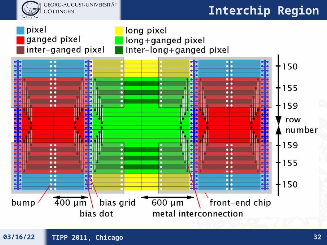
• Typical pixel size 50 x 400 μm2
(50 x 600 μm2 pixels in gaps between FE chips)
• Bias voltage 150 – 600 V
• Readout:
• 16 FE chips, 2880 pixels each
• Zero suppression in the FE chip, MCC builds module event
• Pulse height measured by means of Time over Threshold
• Data transfer 40 – 160 MHz depending on layer
04/19/23 TIPP 2011, Chicago 5
Outline
• The ATLAS Pixel Detector
• Operational Experience
• Tuning, calibration and performance
• Threshold and noise
• Charge measurement
• Timing
• Monitoring detector quality and radiation damage
• Examples of offline performance
04/19/23 TIPP 2011, Chicago 6
Timeline
• May 2007 – Installation in ATLAS
• Sept 2008 – First cosmic events
• Oct 2008 – LHC incident
• Nov 2009 – First beam 450 GeV
• Dec 2009 – 900 GeV collisions
• March 2010 – 7 TeV Collisions
• May 2011 – Luminosity 1033 cm-2 s-1
04/19/23 TIPP 2011, Chicago 7
Calibration
Cosmics
900 GeV Collisions
7 TeV Collisions
Installation
Pixel Detector Status
• 96.7% of the detector active in data taking
• 55 Modules disabled (3.2%)(6 modules due to single optoboard failure)
• 47 FE chips disabled (0.16%)
• In particular FE failures are linked to thermal cycles→ an attempt has been made to reduce the problem by smaller temperature
variations with first modest results, more refinements will be tried
04/19/23 TIPP 2011, Chicago 8
Communication26
Optoboard6
Clock3
LV3
HV17
Disabled modules by failure type: Inactive fraction per layer:
B-layer 3.1 %Layer 1 1.4 %Layer 2 4.6 %Endcap A 2.8 %Endcap C 2.8 %
Outline
• The ATLAS Pixel Detector
• Operational Experience
• Tuning, calibration and performance
• Threshold and noise
• Charge measurement
• Timing
• Monitoring detector quality and radiation damage
• Examples of offline performance
04/19/23 TIPP 2011, Chicago 9
Threshold and Noise
• Threshold scan: inject varying test charges and measure response curve: error function fit yields threshold and noise
• Threshold tuning: inject fixed test charge (threshold target) and vary the in-pixel threshold DAC. 50%-point gives optimal value
• In 2008 started with setting of 4000 e, working out of the box
• Setting now is 3500 e, resulting in an increase in number of masked pixels, but still negligible (0.1%)
• A successful attempt at 3000 e has been made during cosmic data taking but resulted in masking of many high-capacitance pixels
• More careful study will need to be done when beam schedule allows
• At the moment not really necessary as number of split clusters is already greatly reduced at 3500 e
04/19/23 TIPP 2011, Chicago 10
Threshold and Noise
• Typical threshold dispersion after tuning: ~ 40 e
• Very few outliers in all pixel classes
• To be checked whether this can be improved in the tuning algorithms
• Noise for normal pixels ~170 e, higher in ganged pixels (~300 e) due to higher load capacitance
• Reflected in threshold over noise, but still >10 for “worst” pixel class, ~20 for normal pixels
04/19/23 TIPP 2011, Chicago 11
Noise Occupancy
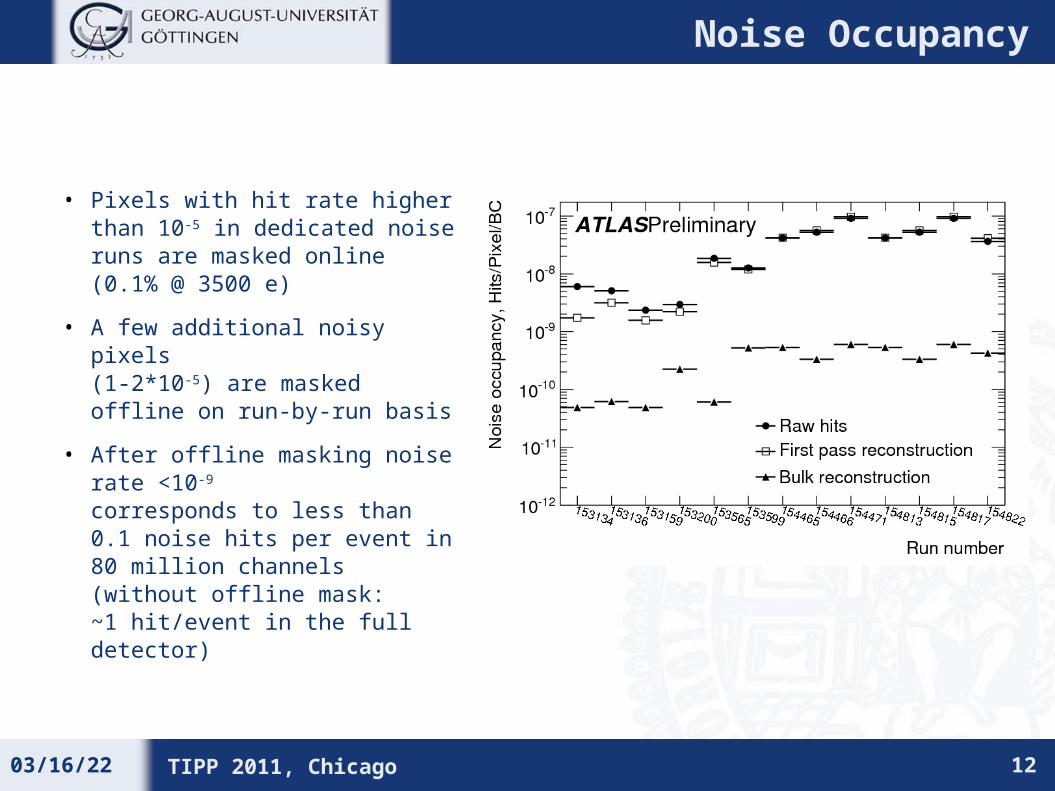
• Pixels with hit rate higher than 10-5 in dedicated noise runs are masked online (0.1% @ 3500 e)
• A few additional noisy pixels (1-2*10-5) are masked offline on run-by-run basis
• After offline masking noise rate <10-9
corresponds to less than 0.1 noise hits per event in 80 million channels(without offline mask: ~1 hit/event in the full detector)
04/19/23 TIPP 2011, Chicago 12
Hit-to-Track Association Efficiency
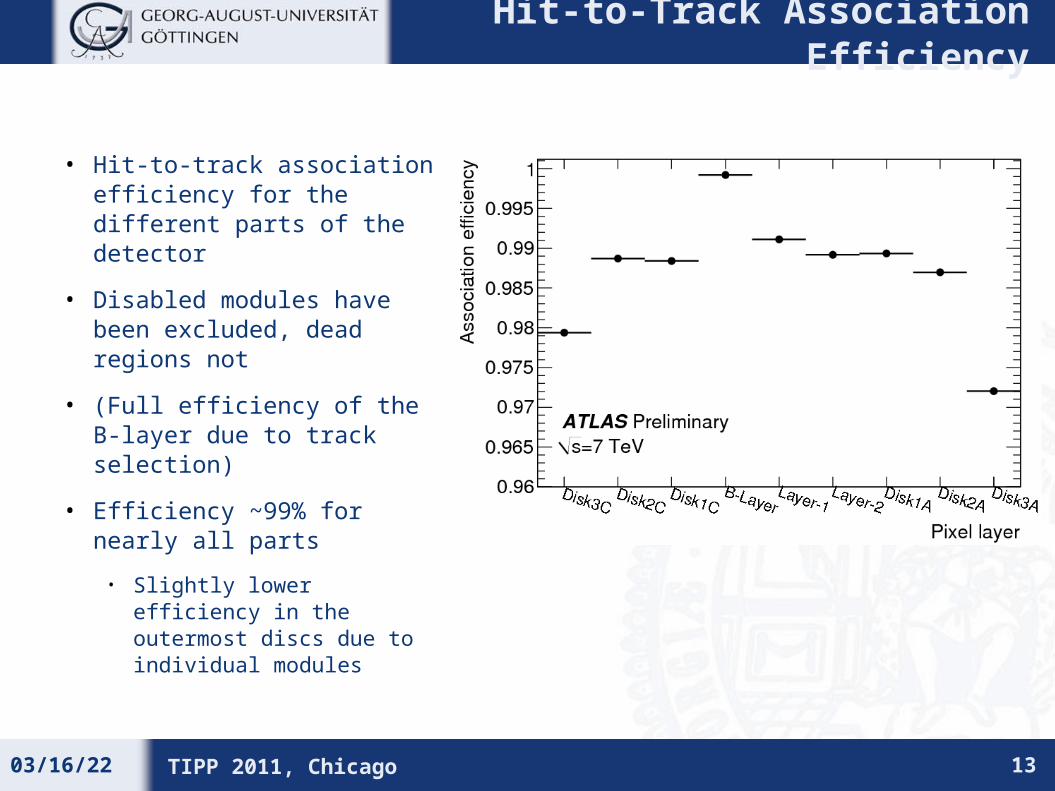
• Hit-to-track association efficiency for the different parts of the detector
• Disabled modules have been excluded, dead regions not
• (Full efficiency of the B-layer due to track selection)
• Efficiency ~99% for nearly all parts
• Slightly lower efficiency in the outermost discs due to individual modules
04/19/23 TIPP 2011, Chicago 13
Outline
• The ATLAS Pixel Detector
• Operational Experience
• Tuning, calibration and performance
• Threshold and noise
• Charge measurement
• Timing
• Monitoring detector quality and radiation damage
• Examples of offline performance
04/19/23 TIPP 2011, Chicago 14
Time-over-Threshold
• Time-over-threshold (ToT, length of discriminator signal) depends on deposited charge
discriminator threshold
feedback current
• Information of the ToT (in units of 25 ns) is read out together with the hit information → measurement of the deposited charge
04/19/23 TIPP 2011, Chicago 15
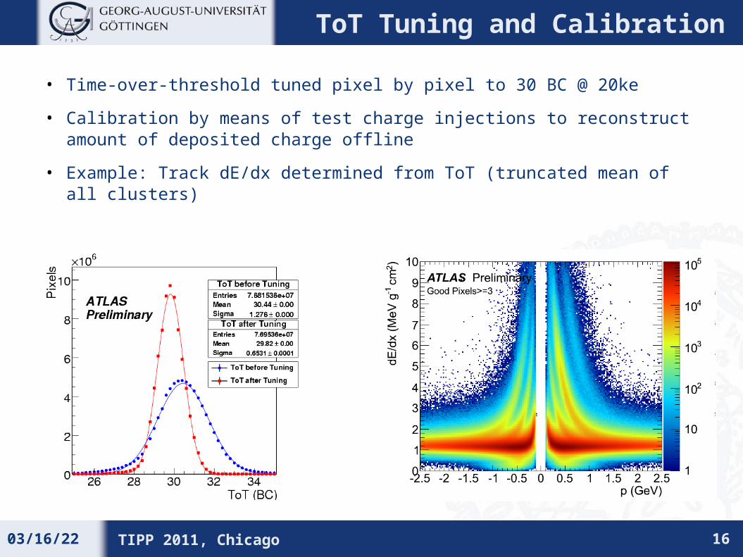
ToT Tuning and Calibration
• Time-over-threshold tuned pixel by pixel to 30 BC @ 20ke
• Calibration by means of test charge injections to reconstruct amount of deposited charge offline
• Example: Track dE/dx determined from ToT (truncated mean of all clusters)
04/19/23 TIPP 2011, Chicago 16
Outline
• The ATLAS Pixel Detector
• Operational Experience
• Tuning, calibration and performance
• Threshold and noise
• Charge measurement
• Timing
• Monitoring detector quality and radiation damage
• Examples of offline performance
04/19/23 TIPP 2011, Chicago 17
Timewalk and In-time Threshold
• Hits with lower charge suffer timewalk
• This leads to an “In-time threshold” higher than the discriminator threshold for a hit detection “in time”
• At 3500 e threshold:
• 4800 e for normal pixels
• Higher load capacitance has been compensated for in ganged and inter-ganged pixels
• Timewalk can be compensated for by on-chip hit doubling (using ToT information)
• In-time threshold 200 e above threshold
• Data volume increases (Testbeam: 10%)
04/19/23 TIPP 2011, Chicago 18
4000 e Threshold
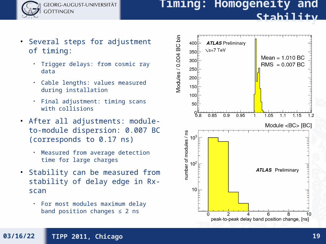
Timing: Homogeneity and Stability
• Several steps for adjustment of timing:
• Trigger delays: from cosmic ray data
• Cable lengths: values measured during installation
• Final adjustment: timing scans with collisions
• After all adjustments: module-to-module dispersion: 0.007 BC(corresponds to 0.17 ns)
• Measured from average detection time for large charges
• Stability can be measured from stability of delay edge in Rx-scan
• For most modules maximum delay band position changes ≤ 2 ns
04/19/23 TIPP 2011, Chicago 19
Outline
• The ATLAS Pixel Detector
• Operational Experience
• Tuning, calibration and performance
• Threshold and noise
• Charge measurement
• Timing
• Monitoring detector quality and radiation damage
• Examples of offline performance
04/19/23 TIPP 2011, Chicago 20
Single-Pixel Leakage Current
• FE-Chip has the possibility to measure leakage current pixel by pixel (“Monleak”)
• Currently majority of pixels at 0
• Measurement range and resolution optimised for after irradiation: LSB ~0.125 nA
• Single-pixel leakage current will be monitored with time
• In addition: we are equipping our DCS hardware with the possibility to measure the single-module leakage current with 20 nA precision
• First channels already equipped, rest following during MD phases
04/19/23 TIPP 2011, Chicago 21
Depletion Voltage
• Goal: measure voltage needed for full depletion VFD during calibration
time
• Idea: use cross-talk, i.e. inject charge into one pixel, read out neighbour
• Before type inversion:
When not fully depleted: (high-ohmic) short between pixels
When fully depleted: pixels are isolated from each other
Chose injected charge such that cross-talk hits are seen only for Vbias < Vpinch-off (≈VFD)
04/19/23 TIPP 2011, Chicago 22
Example: single module close to depletion voltageWhite: (already depleted) pixels with no crosstalk hitsMeasurement shows structure of sensor production
Measured depletion voltage for all modules
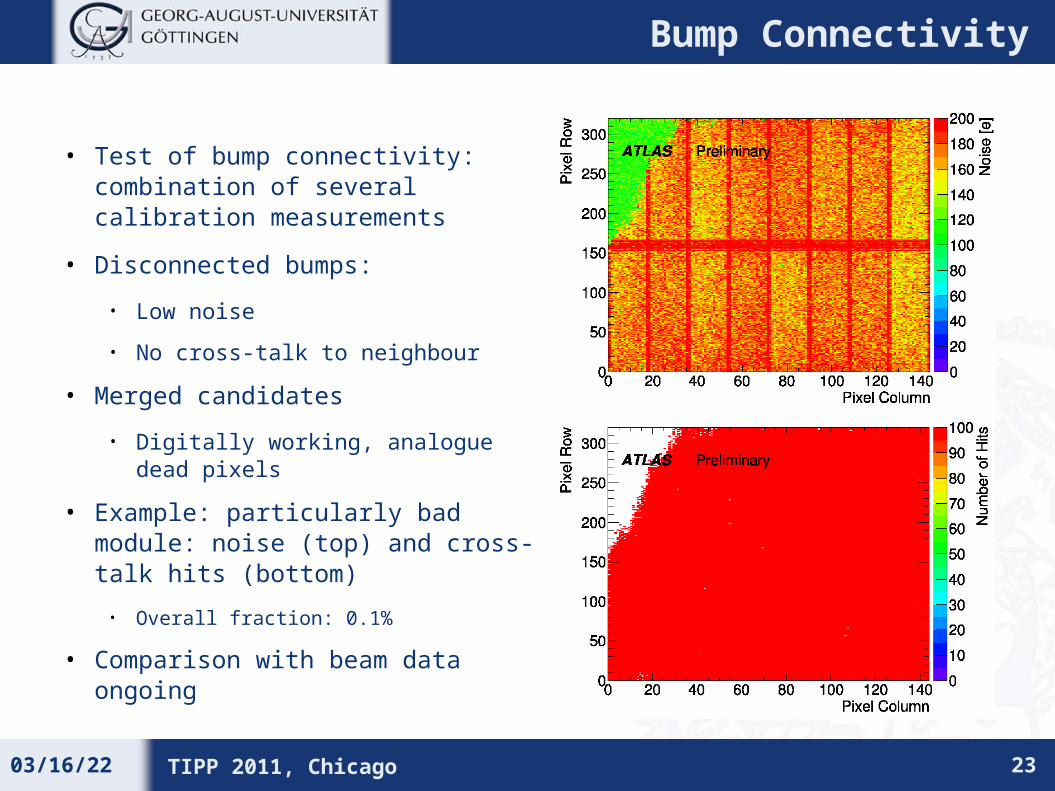
Bump Connectivity
• Test of bump connectivity: combination of several calibration measurements
• Disconnected bumps:
• Low noise
• No cross-talk to neighbour
• Merged candidates
• Digitally working, analogue dead pixels
• Example: particularly bad module: noise (top) and cross-talk hits (bottom)
• Overall fraction: 0.1%
• Comparison with beam data ongoing
04/19/23 TIPP 2011, Chicago 23
Outline
• The ATLAS Pixel Detector
• Operational Experience
• Tuning, calibration and performance
• Threshold and noise
• Charge measurement
• Timing
• Monitoring detector quality and radiation damage
• Examples of offline performance
04/19/23 TIPP 2011, Chicago 24
Charge Sharing
• Charge sharing can be determined from ToT and is used to improve the spatial resolution
• Calibration measurement:
Residuals vs. charge sharing variable
Slope is then used to correct
“digital” hit position
04/19/23 TIPP 2011, Chicago 25
Spatial Resolution
• Residual distribution with newest alignment
• Width close to MC width for a perfectly aligned detector
04/19/23 TIPP 2011, Chicago 26
Lorentz Angle
• Measurement of Lorentz angle from cluster size vs. track angle
• Measured value close to expectation (225 mrad)
04/19/23 TIPP 2011, Chicago 27
Conclusions
• The ATLAS Pixel Detector has been calibrated and tuned to a stable working point
3500 e threshold
Time over Threshold of 30 BC for 20 ke charge
• Performance at this working point is good
− Threshold Dispersion ~ 40 e, average noise ~ 170 e
− 4800 e average in-time threshold
− Charge measurement resolution < 1000 e
− Efficiency 98% - 99%
− Online noise occupancy O(10-8)
− Offline performance as expected
• Now preparing next steps:
Define working points for higher luminosity and (for the somewhat further future) lower signals
Use the available calibration measurements to monitor detector properties over time (leakage current, depletion voltage, bump connectivity)
04/19/23 TIPP 2011, Chicago 28
Backup
04/19/23 TIPP 2011, Chicago 29
Detector Safety
• Until “Stable Beams” are declared from the LHC, the sensor HV is off; This can be bypassed for calibration period.
• Warm start procedure:
Modules are configured at the start of each run
To avoid noise preamplifiers are off as long as HV is off