48
Operations and Maintenance Manual Hydraulic Tail Trailer
Operations and Maintenance Manual
Hydraulic Tail Trailer

Towmaster Trailers Product Manual
3
A forward from Towmaster to our valued customers.
This manual includes operations and maintenance information for our current trailers. We have put forth
our best effort to provide you with current information. However, we build many custom trailers for
various customers and cannot guarantee that your particular unit has features outlined in this manual. If
you encounter this problem please contact your dealer. If they cannot be of assistance, please feel free to
call our Parts Department at 320-593-4595.
To ensure a more productive call have your trailer’s VIN number (serial number) ready as that will be
needed to locate the correct replacement parts and answer your technical questions. As a reminder, some
parts may only be available through our dealer network. We cannot sell some parts directly. The Team at
Towmaster will make every effort to get you up and running and keep your trailer ownership as trouble
free as possible.

Towmaster Trailers Product Manual
5
TABLE OF CONTENTS
Warranty Information
Reporting Safety Defects
SECTION I - Trailer and Dealer Information
SECTION II - Safety and Controls
SECTION III - Operations
SECTION IV - Tire Safety Information
SECTION IV - Maintenance
7
8
9
13
21
29
41
…...................
…...................
…...................
…...................
…...................
…...................
…...................

Towmaster Trailers Product Manual
7
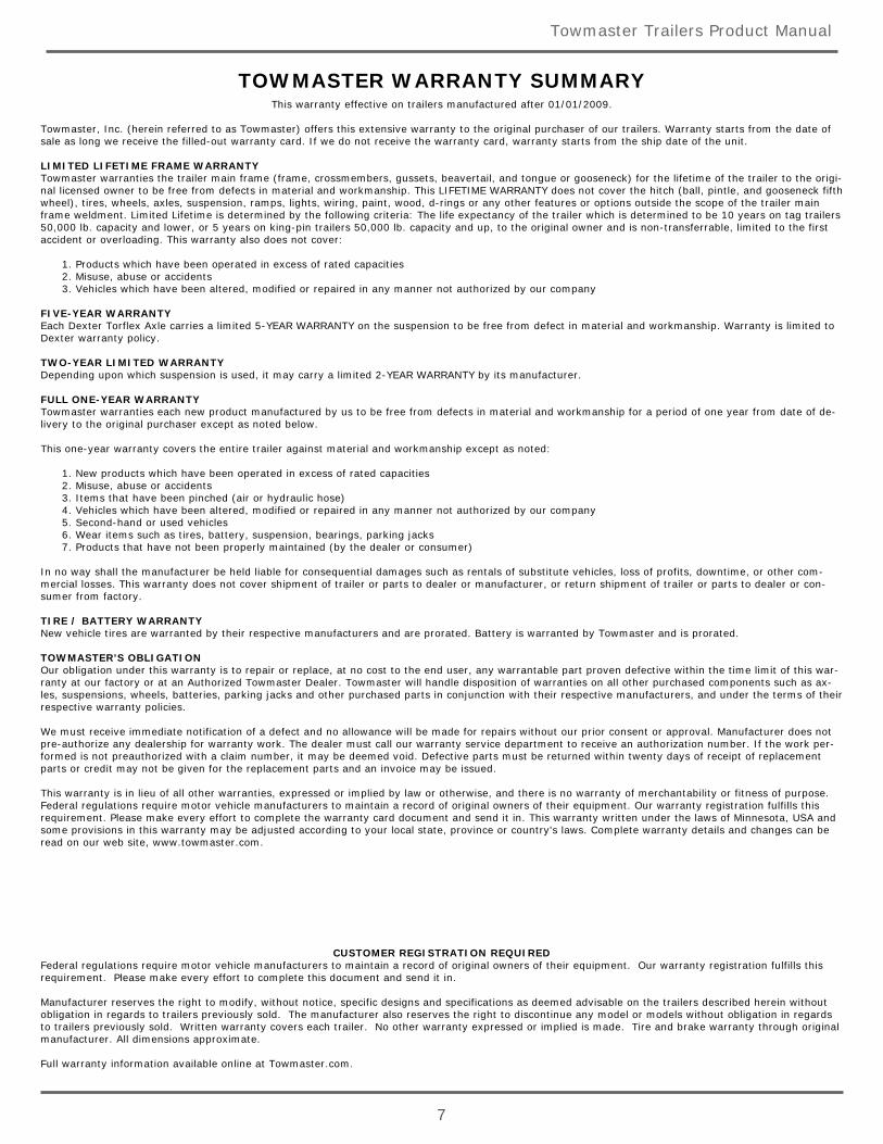
TOWMASTER WARRANTY SUMMARYThis warranty effective on trailers manufactured after 01/01/2009.
Towmaster, Inc. (herein referred to as Towmaster) offers this extensive warranty to the original purchaser of our trailers. Warranty starts from the date ofsale as long we receive the filled-out warranty card. If we do not receive the warranty card, warranty starts from the ship date of the unit.
LIMITED LIFETIME FRAME WARRANTYTowmaster warranties the trailer main frame (frame, crossmembers, gussets, beavertail, and tongue or gooseneck) for the lifetime of the trailer to the origi-nal licensed owner to be free from defects in material and workmanship. This LIFETIME WARRANTY does not cover the hitch (ball, pintle, and gooseneck fifthwheel), tires, wheels, axles, suspension, ramps, lights, wiring, paint, wood, d-rings or any other features or options outside the scope of the trailer mainframe weldment. Limited Lifetime is determined by the following criteria: The life expectancy of the trailer which is determined to be 10 years on tag trailers50,000 lb. capacity and lower, or 5 years on king-pin trailers 50,000 lb. capacity and up, to the original owner and is non-transferrable, limited to the firstaccident or overloading. This warranty also does not cover:
1. Products which have been operated in excess of rated capacities 2. Misuse, abuse or accidents 3. Vehicles which have been altered, modified or repaired in any manner not authorized by our company
FIVE-YEAR WARRANTYEach Dexter Torflex Axle carries a limited 5-YEAR WARRANTY on the suspension to be free from defect in material and workmanship. Warranty is limited toDexter warranty policy.
TWO-YEAR LIMITED WARRANTYDepending upon which suspension is used, it may carry a limited 2-YEAR WARRANTY by its manufacturer.
FULL ONE-YEAR WARRANTYTowmaster warranties each new product manufactured by us to be free from defects in material and workmanship for a period of one year from date of de-livery to the original purchaser except as noted below.
This one-year warranty covers the entire trailer against material and workmanship except as noted:
1. New products which have been operated in excess of rated capacities 2. Misuse, abuse or accidents 3. Items that have been pinched (air or hydraulic hose) 4. Vehicles which have been altered, modified or repaired in any manner not authorized by our company 5. Second-hand or used vehicles 6. Wear items such as tires, battery, suspension, bearings, parking jacks 7. Products that have not been properly maintained (by the dealer or consumer)
In no way shall the manufacturer be held liable for consequential damages such as rentals of substitute vehicles, loss of profits, downtime, or other com-mercial losses. This warranty does not cover shipment of trailer or parts to dealer or manufacturer, or return shipment of trailer or parts to dealer or con-sumer from factory.
TIRE / BATTERY WARRANTYNew vehicle tires are warranted by their respective manufacturers and are prorated. Battery is warranted by Towmaster and is prorated.
TOWMASTER'S OBLIGATIONOur obligation under this warranty is to repair or replace, at no cost to the end user, any warrantable part proven defective within the time limit of this war-ranty at our factory or at an Authorized Towmaster Dealer. Towmaster will handle disposition of warranties on all other purchased components such as ax-les, suspensions, wheels, batteries, parking jacks and other purchased parts in conjunction with their respective manufacturers, and under the terms of theirrespective warranty policies.
We must receive immediate notification of a defect and no allowance will be made for repairs without our prior consent or approval. Manufacturer does notpre-authorize any dealership for warranty work. The dealer must call our warranty service department to receive an authorization number. If the work per-formed is not preauthorized with a claim number, it may be deemed void. Defective parts must be returned within twenty days of receipt of replacementparts or credit may not be given for the replacement parts and an invoice may be issued.
This warranty is in lieu of all other warranties, expressed or implied by law or otherwise, and there is no warranty of merchantability or fitness of purpose.Federal regulations require motor vehicle manufacturers to maintain a record of original owners of their equipment. Our warranty registration fulfills thisrequirement. Please make every effort to complete the warranty card document and send it in. This warranty written under the laws of Minnesota, USA andsome provisions in this warranty may be adjusted according to your local state, province or country's laws. Complete warranty details and changes can beread on our web site, www.towmaster.com.
CUSTOMER REGISTRATION REQUIREDFederal regulations require motor vehicle manufacturers to maintain a record of original owners of their equipment. Our warranty registration fulfills thisrequirement. Please make every effort to complete this document and send it in.
Manufacturer reserves the right to modify, without notice, specific designs and specifications as deemed advisable on the trailers described herein withoutobligation in regards to trailers previously sold. The manufacturer also reserves the right to discontinue any model or models without obligation in regardsto trailers previously sold. Written warranty covers each trailer. No other warranty expressed or implied is made. Tire and brake warranty through originalmanufacturer. All dimensions approximate.
Full warranty information available online at Towmaster.com.
Towmaster Trailers Product Manual
8
Reporting Safety Defects
If you believe that your vehicle has a defect which could cause a crash or could cause injury or death, you
should immediately inform the National Highway Traffic Safety Administration (NHTSA) in addition to
notifying Towmaster, Inc.
If NHTSA receives similar complaints, it may open an investigation, and if it finds that a safety defect
exists in a group of vehicles, it may order a recall and remedy campaign. However, NHTSA cannot
become involved in individual problems between you, your dealer, or Towmaster, Inc.
To contact NHTSA, you may either call the Auto Safety Hotline toll-free at 1-800-424-9393 or write to:
NHTSAU.S. Department of Transportation
400 7th Street SW NSA-11 Washington, DC 20590
You may also obtain other information about motor vehicle safety from www.safecar.gov.

Towmaster Trailers Product Manual
9
SECTION ITRAILER INFORMATION
Trailer and Dealer Information
Truck Requirements
11
12
…...................
…...................

Towmaster Trailers Product Manual
11
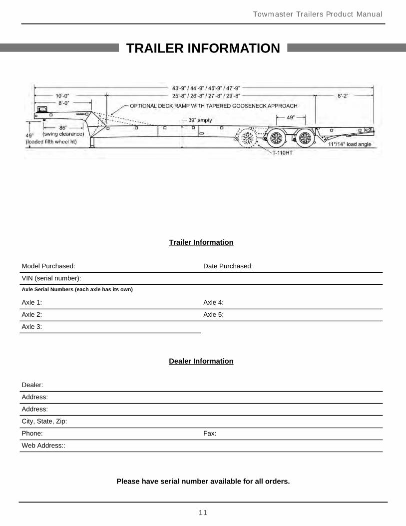
TRAILER INFORMATION
Trailer Information
Model Purchased: Date Purchased:
VIN (serial number):Axle Serial Numbers (each axle has its own)
Axle 1: Axle 4:
Axle 2: Axle 5:
Axle 3:
Dealer Information
Dealer:
Address:
Address:
City, State, Zip:
Phone: Fax:
Web Address::
Please have serial number available for all orders.

Towmaster Trailers Product Manual
12
TRUCK REQUIREMENTS / OPERATING RANGES
P.S.I. - 2,800 to 3,000
G.P.M. - 10 GPM minimum, 25 GPM maximum
Swing Clearance - See truck dimensions (page 5)
5th Wheel Height - 47" - 52" See truck dimensions (page 5)
Hydraulic Connections - See below...
COUPLER NIPPLETowmaster P/N: 37-5972 Towmaster P/N: 37-5971
COUPLERBODY SIZE 3/4THREAD SIZE (NPTF) 3/4-14DIM. A 3.36DIM. B 1.62DIM. C 1.90
NIPPLEBODY SIZE 3/4THREAD SIZE (NPTF) 3/4-14DIM. D 2.28DIM. E 1.18DIM. F 1.38DIM. G 1.59
Towmaster Trailers Product Manual
13
SECTION IISAFETY AND CONTROLS
General Safety
Operation Controls
Decals
Pre-Trip Inspection
15
17
18
20
…...................
…...................
…...................
…...................


Towmaster Trailers Product Manual
15
GENERAL SAFETY INFORMATION
READ OPERATIONS MANUAL
Before operating the trailer, you must read and understand the safety precautions and operationinstructions found in this manual. Never allow anyone to operation the trailer who does notunderstand the safety warnings or proper operation of the trailer.
SAFETY SHIELDS AND DECALS
All equipment and attachments must be kept in good condition for proper safety and operation.Replace all worn, damaged, unusable, or missing safety shields and guards prior to operatingequipment.
Safety decals must be in good, readable condition. Replace decals if they become worn or damagedor are missing from the proper area. New decals can be obtained through our parts and servicedepartment (320-593-4595). Decals must be in place before operating the trailer.
EQUIPMENT AND CONTROLS
Never modify the trailer. Altering this equipment in any manner which adversely affects itsoperation, performance, durability, or use will void the warranty and may cause hazardousconditions.
Know the location and function of all controls and how to stop the equipment in an emergencybefore operating the trailer.
Keep all screws, nuts, and bolts properly tightened and all moveable parts properly maintained.
If replacing a part, use only parts that meet or exceed factory specifications. Follow recommendedtorque specifications.
SAFETY WARNING
Make sure all lights are in proper working condition and all tires are properly maintained andinflated.
Brakes should be inspected and maintained at proper intervals.
Electrical, air, and hydraulic lines must be clean and in working order.
Know your trailer and your load. You must adhere to D.O.T. loading and tie-down safety standards.
Make sure the area is clear and the trailer is parked on level ground before loading or unloadingequipment.
Read all safety and operations decals prior to operating the trailer.
Ramp surface must be clean of debris and dry (not slippery) when loading or unloading.
Avoid pinch points and keep everyone clear of moving parts.
Load with the center of gravity of the equipment as low as possible.
Con’t.
Towmaster Trailers Product Manual
16
SAFETY WARNING - CON’T.
Drive equipment slowly onto trailer and avoid sudden maneuvers.
Secure equipment and all attachments properly to the trailer prior to moving trailer.
WHEN USING WINCH (if equipped)
DO NOT allow riders on equipment being winched onto the trailer.
Keep people away from the area in front of or behind the equipment being loaded.
Anchor the winch cable around the drum with a minimum of 5 wraps before using.
NEVER touch the winch cable under load.
The winch cable is not design to secure the load to the trailer.
MAINTENANCE SAFETY
Always wear safety glasses while servicing the equipment.
Follow recommended lubrication schedule to prevent equipment failures.
Hydraulic fluid is under pressure and can cause personal injury. Relieve all pressure in thehydraulic system before disconnecting or reconnecting hydraulic hoses.
Use a piece of cardboard or wood to check for hydraulic leaks. Never use your hands as hydraulicfluid under pressure can penetrate skin, even through gloves.
If the trailer must be raised for service, use only jacks or hoists with the required capacity to liftthe trailer and then support the trailer with approved jackstands while working on it. Jacks andhoists can fail.
Use genuine factory replacement parts.
Unless otherwise noted, illustrations and photos in this manual are for reference only as equipmentand specifications may vary from unit to unit.
Never reuse lock washers or locknuts. Always replace with new as they can lose their grippingpower.
Follow recommended torque specifications for all hardware and do not over tighten.
Do not wear loose clothing or jewelry when working on the trailer.
Test all work prior to releasing the equipment back into service.
GENERAL SAFETY INFORMATION
Towmaster Trailers Product Manual
17
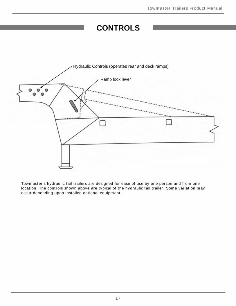
CONTROLS
Hydraulic Controls (operates rear and deck ramps)
Ramp lock lever
Towmaster’s hydraulic tail trailers are designed for ease of use by one person and from onelocation. The controls shown above are typical of the hydraulic tail trailer. Some variation mayoccur depending upon installed optional equipment.

Towmaster Trailers Product Manual
18
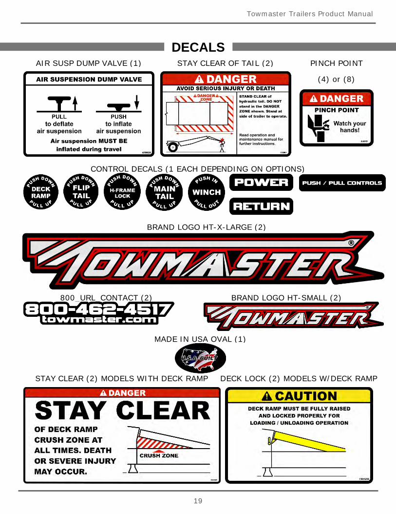
DECALSThe following is a list of decals on the Hydraulic Tail trailer. Some decals may only
appear on trailers with the available options as noted.
MODELS WITHOUT DECK RAMP MODELS WITH DECK RAMP
MODELS WITH WINCH
GENERAL CAUTION (1)
Towmaster Trailers Product Manual
19
DECALS
STAY CLEAR (2) MODELS WITH DECK RAMP
800_URL_CONTACT (2) BRAND LOGO HT-SMALL (2)
BRAND LOGO HT-X-LARGE (2)
MADE IN USA OVAL (1)
CONTROL DECALS (1 EACH DEPENDING ON OPTIONS)
DECK LOCK (2) MODELS W/DECK RAMP
AIR SUSP DUMP VALVE (1) STAY CLEAR OF TAIL (2) PINCH POINT
(4) or (8)
Towmaster Trailers Product Manual
20
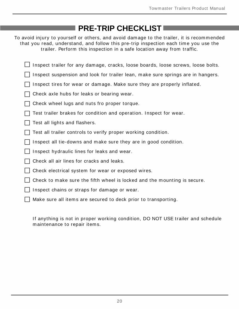
PRE-TRIP CHECKLISTTo avoid injury to yourself or others, and avoid damage to the trailer, it is recommended
that you read, understand, and follow this pre-trip inspection each time you use thetrailer. Perform this inspection in a safe location away from traffic.
Inspect trailer for any damage, cracks, loose boards, loose screws, loose bolts.
Inspect suspension and look for trailer lean, make sure springs are in hangers.
Inspect tires for wear or damage. Make sure they are properly inflated.
Check axle hubs for leaks or bearing wear.
Check wheel lugs and nuts fro proper torque.
Test trailer brakes for condition and operation. Inspect for wear.
Test all lights and flashers.
Test all trailer controls to verify proper working condition.
Inspect all tie-downs and make sure they are in good condition.
Inspect hydraulic lines for leaks and wear.
Check all air lines for cracks and leaks.
Check electrical system for wear or exposed wires.
Check to make sure the fifth wheel is locked and the mounting is secure.
Inspect chains or straps for damage or wear.
Make sure all items are secured to deck prior to transporting.
If anything is not in proper working condition, DO NOT USE trailer and schedulemaintenance to repair items.
Towmaster Trailers Product Manual
21
SECTION IIIOPERATIONS
Upper Deck Ramp
Hydraulic Tail Section - Loading/Unloading
Hydraulic Tail Section - Transport
Winch
Parking Jacks
23
24
26
27
27
…...................
…...................
…...................
…...................
…...................

Towmaster Trailers Product Manual
22
Towmaster Trailers Product Manual
23
OPERATIONS
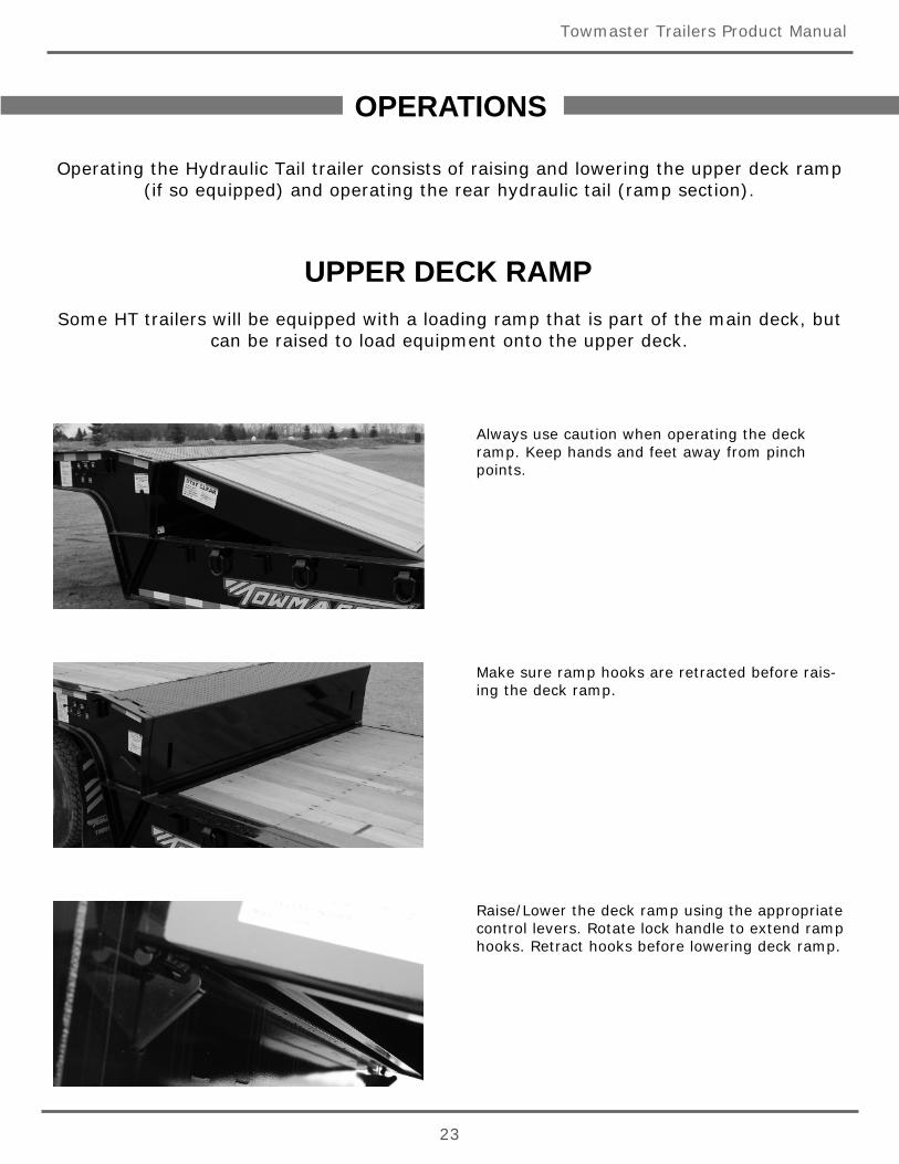
Operating the Hydraulic Tail trailer consists of raising and lowering the upper deck ramp(if so equipped) and operating the rear hydraulic tail (ramp section).
Always use caution when operating the deckramp. Keep hands and feet away from pinchpoints.
Make sure ramp hooks are retracted before rais-ing the deck ramp.
Raise/Lower the deck ramp using the appropriatecontrol levers. Rotate lock handle to extend ramphooks. Retract hooks before lowering deck ramp.
UPPER DECK RAMPSome HT trailers will be equipped with a loading ramp that is part of the main deck, but
can be raised to load equipment onto the upper deck.
Towmaster Trailers Product Manual
24
OPERATIONS
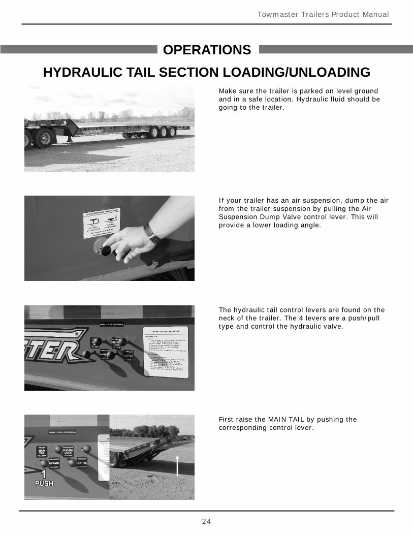
Make sure the trailer is parked on level groundand in a safe location. Hydraulic fluid should begoing to the trailer.
If your trailer has an air suspension, dump the airfrom the trailer suspension by pulling the AirSuspension Dump Valve control lever. This willprovide a lower loading angle.
The hydraulic tail control levers are found on theneck of the trailer. The 4 levers are a push/pulltype and control the hydraulic valve.
First raise the MAIN TAIL by pushing thecorresponding control lever.
HYDRAULIC TAIL SECTION LOADING/UNLOADING
Towmaster Trailers Product Manual
25
OPERATIONS
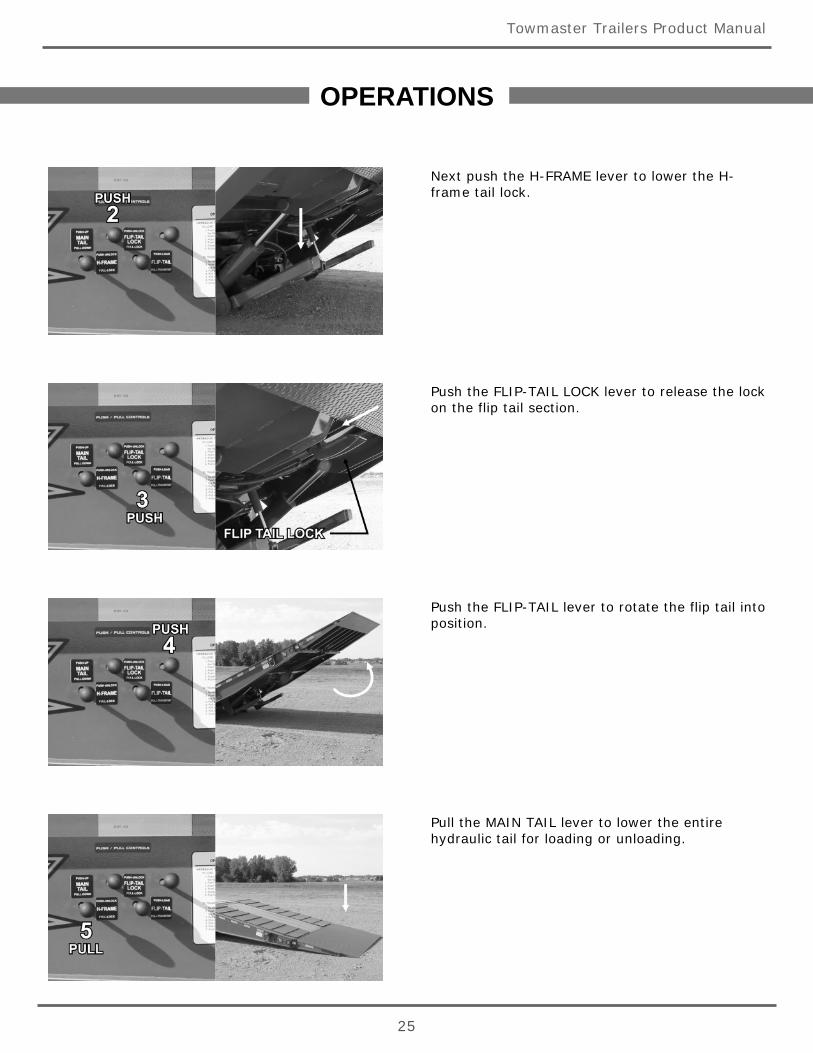
Next push the H-FRAME lever to lower the H-frame tail lock.
Push the FLIP-TAIL LOCK lever to release the lockon the flip tail section.
Push the FLIP-TAIL lever to rotate the flip tail intoposition.
Pull the MAIN TAIL lever to lower the entirehydraulic tail for loading or unloading.
Towmaster Trailers Product Manual
26
OPERATIONS
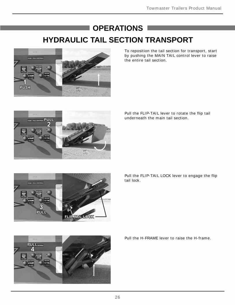
To reposition the tail section for transport, startby pushing the MAIN TAIL control lever to raisethe entire tail section.
Pull the FLIP-TAIL lever to rotate the flip tailunderneath the main tail section.
Pull the FLIP-TAIL LOCK lever to engage the fliptail lock.
Pull the H-FRAME lever to raise the H-frame.
HYDRAULIC TAIL SECTION TRANSPORT
Towmaster Trailers Product Manual
27
OPERATIONS
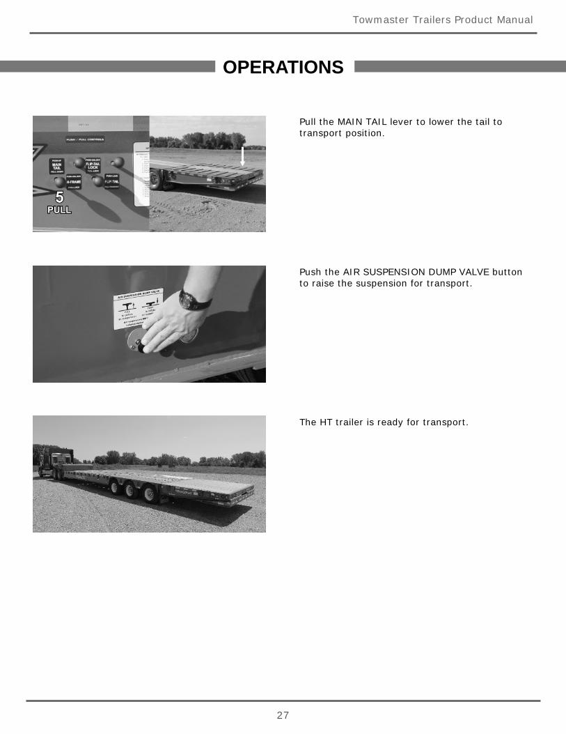
Pull the MAIN TAIL lever to lower the tail totransport position.
Push the AIR SUSPENSION DUMP VALVE buttonto raise the suspension for transport.
The HT trailer is ready for transport.
Towmaster Trailers Product Manual
28
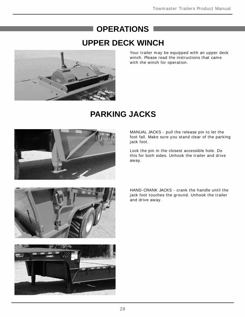
Your trailer may be equipped with an upper deckwinch. Please read the instructions that camewith the winch for operation.
HAND-CRANK JACKS - crank the handle until thejack foot touches the ground. Unhook the trailerand drive away.
UPPER DECK WINCHOPERATIONS
PARKING JACKS
MANUAL JACKS - pull the release pin to let thefoot fall. Make sure you stand clear of the parkingjack foot.
Lock the pin in the closest accessible hole. Dothis for both sides. Unhook the trailer and driveaway.
G.V.W.R.(Gross Vehicle Weight Rating)
and
TIRE SAFETY INFORMATION
A recent law was enacted that requires trailer manufacturers to place a tire andloading information decal placed near the serial tag on a trailer as well as detailedinformation on loading and tires in the owner’s manual on all trailers with a GVWR(Gross Vehicle Weight Rating) of 10,000 lbs. or less. This section of our manualcovers the required information.
TIRE AND SAFETY INFORMATIONThis portion of the User’s Manual contains tire safety information as required by 49 CFR 575.6.
Section 1.1 contains “Steps for Determining Correct Load Limit - Trailer”.
Section 1.2 contains “Steps for Determining Correct Load Limit – Tow Vehicle”.
Section 1.3 contains a Glossary of Tire Terminology, including “cold inflation pressure”, “maximum inflation pressure”,“recommended inflation pressure”, and other non-technical terms.
Section 1.4 contains information from the NHTSA brochure entitled “Tire Safety – Everything Rides On It”.
This brochure, as well as the preceding subsections, describes the following items;
Tire labeling, including a description and explanation of each marking on the tires, and information about the DOT TireIdentification Number (TIN).
Recommended tire inflation pressure, including a description and explanation of:
A. Cold inflation pressure.
B. Vehicle Placard and location on the vehicle.
C. Adverse safety consequences of under inflation (including tire failure).
D. Measuring and adjusting air pressure for proper inflation.
E. Tire Care, including maintenance and safety practices.
Vehicle load limits, including a description and explanation of the following items:
A. Locating and understanding the load limit information, total load capacity, and cargo capacity.
B. Calculating total and cargo capacities with varying seating configurations including quantitative examples showing /illustrating how the vehicles cargo and luggage capacity decreases as combined number and size of occupants’increases. This item is also discussed in Section 3.
C. Determining compatibility of tire and vehicle load capabilities.
D. Adverse safety consequences of overloading on handling and stopping on tires.
1.1. Steps for Determining Correct Load Limit – Trailer
Determining the load limits of a trailer includes more than understanding the load limits of the tires alone. On all trailersthere is a Federal certification/VIN label that is located on the forward half of the left (road) side of the unit. Thiscertification/VIN label will indicate the trailer’s Gross Vehicle Weight Rating (GVWR). This is the most weight the fully loadedtrailer can weigh. It will also provide the Gross Axle Weight Rating (GAWR). This is the most a particular axle can weigh. Ifthere are multiple axles, the GAWR of each axle will be provided.
If your trailer has a GVWR of 10,000 pounds or less, there is a vehicle placard located in the same location as thecertification label described above. This placard provides tire and loading information. In addition, this placard will show astatement regarding maximum cargo capacity. Cargo can be added to the trailer, up to the maximum weight specified onthe placard. The combined weight of the cargo is provided as a single number. In any case, remember: the total weight of afully loaded trailer can not exceed the stated GVWR.
TIRE AND SAFETY INFORMATION
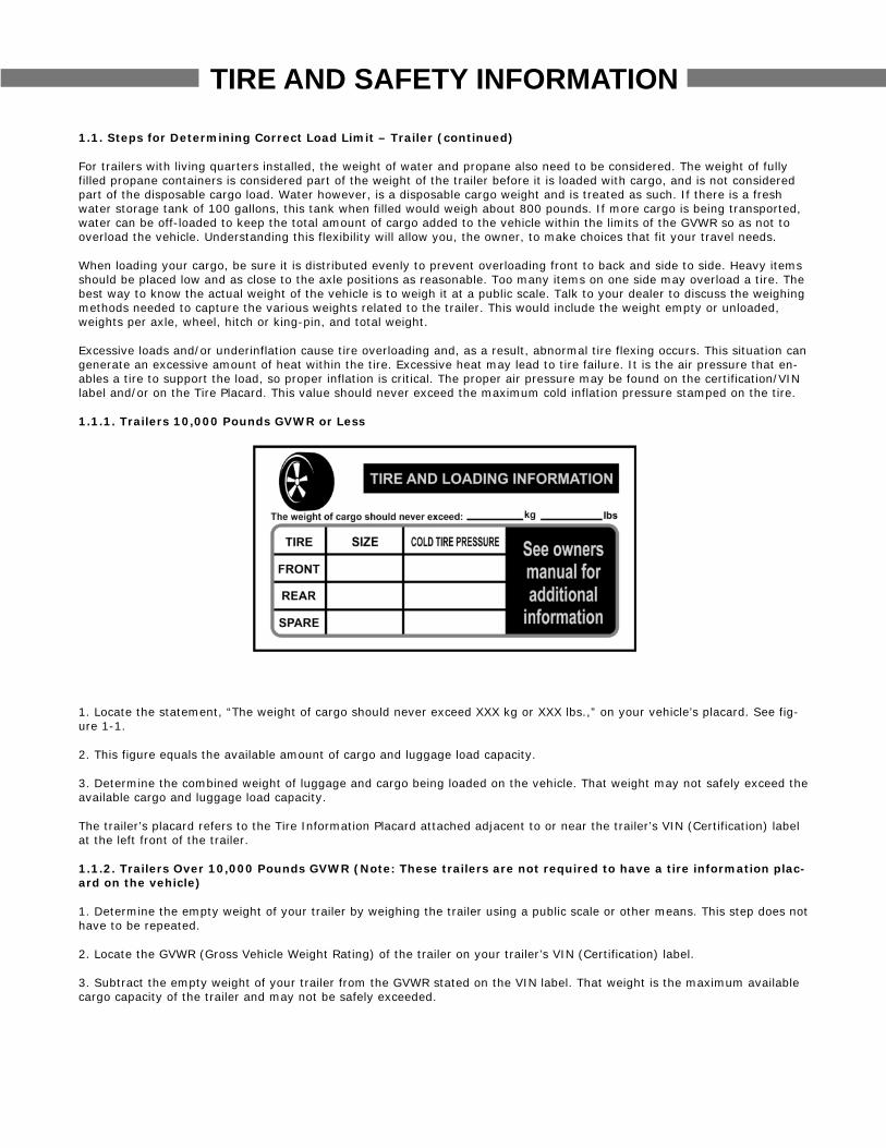
1.1. Steps for Determining Correct Load Limit – Trailer (continued)
For trailers with living quarters installed, the weight of water and propane also need to be considered. The weight of fullyfilled propane containers is considered part of the weight of the trailer before it is loaded with cargo, and is not consideredpart of the disposable cargo load. Water however, is a disposable cargo weight and is treated as such. If there is a freshwater storage tank of 100 gallons, this tank when filled would weigh about 800 pounds. If more cargo is being transported,water can be off-loaded to keep the total amount of cargo added to the vehicle within the limits of the GVWR so as not tooverload the vehicle. Understanding this flexibility will allow you, the owner, to make choices that fit your travel needs.
When loading your cargo, be sure it is distributed evenly to prevent overloading front to back and side to side. Heavy itemsshould be placed low and as close to the axle positions as reasonable. Too many items on one side may overload a tire. Thebest way to know the actual weight of the vehicle is to weigh it at a public scale. Talk to your dealer to discuss the weighingmethods needed to capture the various weights related to the trailer. This would include the weight empty or unloaded,weights per axle, wheel, hitch or king-pin, and total weight.
Excessive loads and/or underinflation cause tire overloading and, as a result, abnormal tire flexing occurs. This situation cangenerate an excessive amount of heat within the tire. Excessive heat may lead to tire failure. It is the air pressure that en-ables a tire to support the load, so proper inflation is critical. The proper air pressure may be found on the certification/VINlabel and/or on the Tire Placard. This value should never exceed the maximum cold inflation pressure stamped on the tire.
1.1.1. Trailers 10,000 Pounds GVWR or Less
1. Locate the statement, “The weight of cargo should never exceed XXX kg or XXX lbs.,” on your vehicle’s placard. See fig-ure 1-1.
2. This figure equals the available amount of cargo and luggage load capacity.
3. Determine the combined weight of luggage and cargo being loaded on the vehicle. That weight may not safely exceed theavailable cargo and luggage load capacity.
The trailer’s placard refers to the Tire Information Placard attached adjacent to or near the trailer’s VIN (Certification) labelat the left front of the trailer.
1.1.2. Trailers Over 10,000 Pounds GVWR (Note: These trailers are not required to have a tire information plac-ard on the vehicle)
1. Determine the empty weight of your trailer by weighing the trailer using a public scale or other means. This step does nothave to be repeated.
2. Locate the GVWR (Gross Vehicle Weight Rating) of the trailer on your trailer’s VIN (Certification) label.
3. Subtract the empty weight of your trailer from the GVWR stated on the VIN label. That weight is the maximum availablecargo capacity of the trailer and may not be safely exceeded.
TIRE AND SAFETY INFORMATION
1.2. Steps for Determining Correct Load Limit – Tow Vehicle
1. Locate the statement, “The combined weight of occupants and cargo should never exceed XXX lbs.,” on your vehicle’splacard.
2. Determine the combined weight of the driver and passengers who will be riding in your vehicle.
3. Subtract the combined weight of the driver and passengers from XXX kilograms or XXX pounds.
4. The resulting figure equals the available amount of cargo and luggage capacity. For example, if the “XXX” amount equals1400 lbs. and there will be five 150 lb. passengers in your vehicle, the amount of available cargo and luggage capacity is650 lbs. (1400-750 (5 x 150) = 650 lbs.).
5. Determine the combined weight of luggage and cargo being loaded on the vehicle. That weight may not safely exceed theavailable cargo and luggage capacity calculated in Step # 4.
6. If your vehicle will be towing a trailer, load from your trailer will be transferred to your vehicle. Consult the tow vehicle’smanual to determine how this weight transfer reduces the available cargo and luggage capacity of your vehicle.
1.3. Glossary Of Tire Terminology
Accessory weightThe combined weight (in excess of those standard items which may be replaced) of automatic transmission, power steering,power brakes, power windows, power seats, radio and heater, to the extent that these items are available as factory-installed equipment (whether installed or not).
BeadThe part of the tire that is made of steel wires, wrapped or reinforced by ply cords and that is shaped to fit the rim.
Bead separationThis is the breakdown of the bond between components in the bead.
Bias ply tireA pneumatic tire in which the ply cords that extend to the beads are laid at alternate angles substantially less than 90degrees to the centerline of the tread.
CarcassThe tire structure, except tread and sidewall rubber which, when inflated, bears the load.
ChunkingThe breaking away of pieces of the tread or sidewall.
Cold inflation pressureThe pressure in the tire before you drive.
CordThe strands forming the plies in the tire.
Cord separationThe parting of cords from adjacent rubber compounds.
CrackingAny parting within the tread, sidewall, or inner liner of the tire extending to cord material.
CTA pneumatic tire with an inverted flange tire and rim system in which the rim is designed with rim flanges pointed radiallyinward and the tire is designed to fit on the underside of the rim in a manner that encloses the rim flanges inside the aircavity of the tire.

TIRE AND SAFETY INFORMATION
Curb weightThe weight of a motor vehicle with standard equipment including the maximum capacity of fuel, oil, and coolant, and, if soequipped, air conditioning and additional weight optional engine.
Extra load tireA tire designed to operate at higher loads and at higher inflation pressures than the corresponding standard tire.
GrooveThe space between two adjacent tread ribs.
Gross Axle Weight RatingThe maximum weight that any axle can support, as published on the Certification / VIN label on the front left side of thetrailer. Actual weight determined by weighing each axle on a public scale, with the trailer attached to the towing vehicle.
Gross Vehicle Weight RatingThe maximum weight of the fully loaded trailer, as published on the Certification / VIN label. Actual weight determined byweighing trailer on a public scale, without being attached to the towing vehicle.
Hitch WeightThe downward force exerted on the hitch ball by the trailer coupler.
InnerlinerThe layer(s) forming the inside surface of a tubeless tire that contains the inflating medium within the tire.
Innerliner separationThe parting of the innerliner from cord material in the carcass.
Intended outboard sidewallThe sidewall that contains a white-wall, bears white lettering or bears manufacturer, brand, and/or model name moldingthat is higher or deeper than the same molding on the other sidewall of the tire or the outward facing sidewall of anasymmetrical tire that has a particular side that must always face outward when mounted on a vehicle.
Light truck (LT) tireA tire designated by its manufacturer as primarily intended for use on lightweight trucks or multipurpose passengervehicles.
Load ratingThe maximum load that a tire is rated to carry for a given inflation pressure.
Maximum load ratingThe load rating for a tire at the maximum permissible inflation pressure for that tire.
Maximum permissible inflation pressureThe maximum cold inflation pressure to which a tire may be inflated.
Maximum loaded vehicle weightThe sum of curb weight, accessory weight, vehicle capacity weight, and production options weight.
Measuring rimThe rim on which a tire is fitted for physical dimension requirements.
Pin WeightThe downward force applied to the 5th wheel or gooseneck ball, by the trailer kingpin or gooseneck coupler.
Non-pneumatic rimA mechanical device which, when a non-pneumatic tire assembly incorporates a wheel, supports the tire, and attaches,either integrally or separably, to the wheel center member and upon which the tire is attached.
Non-pneumatic spare tire assemblyA non-pneumatic tire assembly intended for temporary use in place of one of the pneumatic tires and rims that are fitted toa passenger car in compliance with the requirements of this standard.

TIRE AND SAFETY INFORMATION
Non-pneumatic tireA mechanical device which transmits, either directly or through a wheel or wheel center member, the vertical load andtractive forces from the roadway to the vehicle, generates the tractive forces that provide the directional control of thevehicle and does not rely on the containment of any gas or fluid for providing those functions.
Non-pneumatic tire assemblyA non-pneumatic tire, alone or in combination with a wheel or wheel center member, which can be mounted on a vehicle.
Normal occupant weightThis means 68 kilograms (150 lbs.) times the number of occupants specified in the second column of Table I of 49 CFR571.110.
Occupant distributionThe distribution of occupants in a vehicle as specified in the third column of Table I of 49 CFR 571.110.
Open spliceAny parting at any junction of tread, sidewall, or innerliner that extends to cord material.
Outer diameterThe overall diameter of an inflated new tire.
Overall widthThe linear distance between the exteriors of the sidewalls of an inflated tire, including elevations due to labeling,decorations, or protective bands or ribs.
PlyA layer of rubber-coated parallel cords.
Ply separationA parting of rubber compound between adjacent plies.
Pneumatic tireA mechanical device made of rubber, chemicals, fabric and steel or other materials, that, when mounted on an automotivewheel, provides the traction and contains the gas or fluid that sustains the load.
Production options weightThe combined weight of those installed regular production options weighing over 2.3 kilograms (5 lbs.) in excess of thosestandard items which they replace, not previously considered in curb weight or accessory weight, including heavy dutybrakes, ride levelers, roof rack, heavy duty battery, and special trim.
Radial ply tireA pneumatic tire in which the ply cords that extend to the beads are laid at substantially 90 degrees to the centerline of thetread.
Recommended inflation pressureThis is the inflation pressure provided by the vehicle manufacturer on the Tire Information label and on the Certification /VIN tag.
Reinforced tireA tire designed to operate at higher loads and at higher inflation pressures than the corresponding standard tire.
RimA metal support for a tire or a tire and tube assembly upon which the tire beads are seated.
Rim diameterThis means the nominal diameter of the bead seat.
Rim size designationThis means the rim diameter and width.
TIRE AND SAFETY INFORMATION
Rim type designationThis means the industry of manufacturer’s designation for a rim by style or code.
Rim widthThis means the nominal distance between rim flanges.
Section widthThe linear distance between the exteriors of the sidewalls of an inflated tire, excluding elevations due to labeling,decoration, or protective bands.
SidewallThat portion of a tire between the tread and bead.
Sidewall separationThe parting of the rubber compound from the cord material in the sidewall.
Special Trailer (ST) tireThe "ST" is an indication the tire is for trailer use only.
Test rimThe rim on which a tire is fitted for testing, and may be any rim listed as appropriate for use with that tire.
TreadThat portion of a tire that comes into contact with the road.
Tread ribA tread section running circumferentially around a tire.
Tread separationPulling away of the tread from the tire carcass.
Treadwear indicators (TWI)The projections within the principal grooves designed to give a visual indication of the degrees of wear of the tread.
Vehicle capacity weightThe rated cargo and luggage load plus 68 kilograms (150 lbs.) times the vehicle’s designated seating capacity.
Vehicle maximum load on the tireThe load on an individual tire that is determined by distributing to each axle its share of the maximum loaded vehicle weightand dividing by two.
Vehicle normal load on the tireThe load on an individual tire that is determined by distributing to each axle its share of the curb weight, accessory weight,and normal occupant weight (distributed in accordance with Table I of CRF 49 571.110) and dividing by 2.
Weather sideThe surface area of the rim not covered by the inflated tire.
Wheel center memberIn the case of a non-pneumatic tire assembly incorporating a wheel, a mechanical device which attaches, either integrally orseparable, to the non-pneumatic rim and provides the connection between the non-pneumatic rim and the vehicle; or, inthe case of a non-pneumatic tire assembly not incorporating a wheel, a mechanical device which attaches, either integrallyor separable, to the non-pneumatic tire and provides the connection between tire and the vehicle.
Wheel-holding fixtureThe fixture used to hold the wheel and tire assembly securely during testing.
TIRE AND SAFETY INFORMATION
1.4. Tire Safety - Everything Rides On It
The National Traffic Safety Administration (NHTSA) has published a brochure (DOT HS 809 361) that discusses all aspects ofTire Safety, as required by CFR 575.6. This brochure is reproduced in part below. It can be obtained and downloaded fromNHTSA, free of charge, from the following web site:
http://www.nhtsa.dot.gov/cars/rules/TireSafety/ridesonit/tires_index.html
Studies of tire safety show that maintaining proper tire pressure, observing tire and vehicle load limits (not carrying moreweight in your vehicle than your tires or vehicle can safely handle), avoiding road hazards, and inspecting tires for cuts,slashes, and other irregularities are the most important things you can do to avoid tire failure, such as tread separation orblowout and flat tires. These actions, along with other care and maintenance activities, can also:
- Improve vehicle handling - Help protect you and others from avoidable breakdowns and accidents - Improve fuel economy - Increase the life of your tires.
This area presents a comprehensive overview of tire safety, including information on the following topics:
- Basic tire maintenance - Uniform Tire Quality Grading System - Fundamental characteristics of tires - Tire safety tips.
Use this information to make tire safety a regular part of your vehicle maintenance routine. Recognize that the time youspend is minimal compared with the inconvenience and safety consequences of a flat tire or other tire failure.
1.5. Safety First–Basic Tire Maintenance
Properly maintained tires improve the steering, stopping, traction, and load-carrying capability of your vehicle.Underinflated tires and overloaded vehicles are a major cause of tire failure. Therefore, as mentioned above, to avoid flattires and other types of tire failure, you should maintain proper tire pressure, observe tire and vehicle load limits, avoid roadhazards, and regularly inspect your tires.
1.5.1. Finding Your Vehicle's Recommended Tire Pressure and Load Limits
Tire information placards and vehicle certification labels contain information on tires and load limits. These labels indicatethe vehicle manufacturer's information including:
- Recommended tire size - Recommended tire inflation pressure - Vehicle capacity weight (VCW–the maximum occupant and cargo weight a vehicle is designed to carry) - Front and rear gross axle weight ratings (GAWR– the maximum weight the axle systems are designed to carry).
Both placards and certification labels are permanently attached to the trailer near the left front.
1.5.2. Understanding Tire Pressure and Load Limits
Tire inflation pressure is the level of air in the tire that provides it with load-carrying capacity and affects the overallperformance of the vehicle. The tire inflation pressure is a number that indicates the amount of air pressure– measured inpounds per square inch (psi)–a tire requires to be properly inflated. (You will also find this number on the vehicleinformation placard expressed in kilopascals (kpa), which is the metric measure used internationally.)
TIRE AND SAFETY INFORMATION
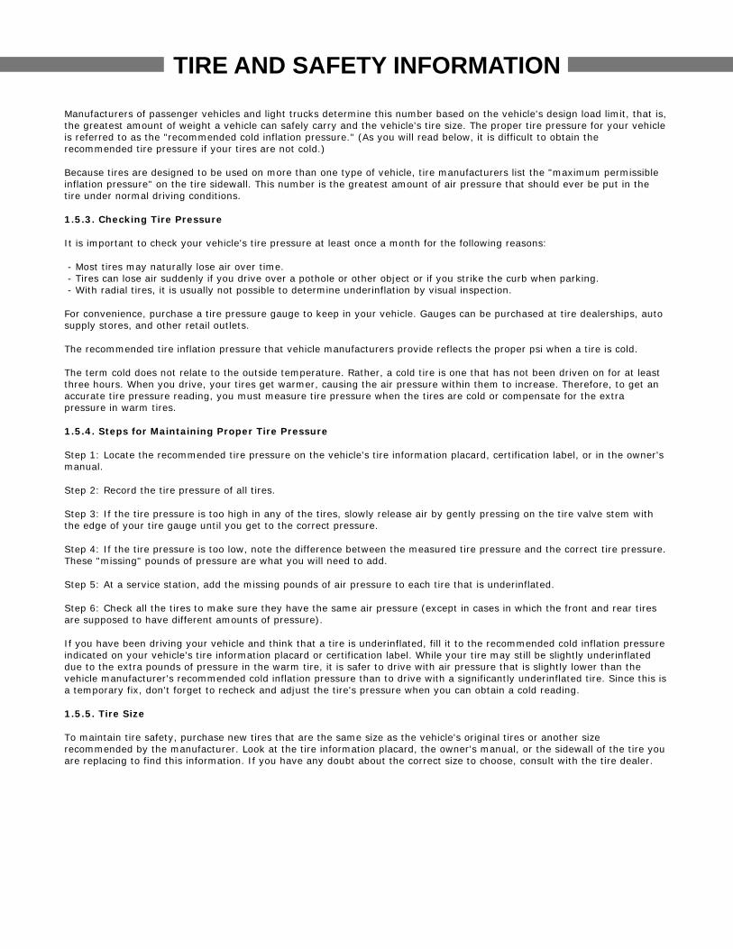
Manufacturers of passenger vehicles and light trucks determine this number based on the vehicle's design load limit, that is,the greatest amount of weight a vehicle can safely carry and the vehicle's tire size. The proper tire pressure for your vehicleis referred to as the "recommended cold inflation pressure." (As you will read below, it is difficult to obtain therecommended tire pressure if your tires are not cold.)
Because tires are designed to be used on more than one type of vehicle, tire manufacturers list the "maximum permissibleinflation pressure" on the tire sidewall. This number is the greatest amount of air pressure that should ever be put in thetire under normal driving conditions.
1.5.3. Checking Tire Pressure
It is important to check your vehicle's tire pressure at least once a month for the following reasons:
- Most tires may naturally lose air over time. - Tires can lose air suddenly if you drive over a pothole or other object or if you strike the curb when parking. - With radial tires, it is usually not possible to determine underinflation by visual inspection.
For convenience, purchase a tire pressure gauge to keep in your vehicle. Gauges can be purchased at tire dealerships, autosupply stores, and other retail outlets.
The recommended tire inflation pressure that vehicle manufacturers provide reflects the proper psi when a tire is cold.
The term cold does not relate to the outside temperature. Rather, a cold tire is one that has not been driven on for at leastthree hours. When you drive, your tires get warmer, causing the air pressure within them to increase. Therefore, to get anaccurate tire pressure reading, you must measure tire pressure when the tires are cold or compensate for the extrapressure in warm tires.
1.5.4. Steps for Maintaining Proper Tire Pressure
Step 1: Locate the recommended tire pressure on the vehicle's tire information placard, certification label, or in the owner'smanual.
Step 2: Record the tire pressure of all tires.
Step 3: If the tire pressure is too high in any of the tires, slowly release air by gently pressing on the tire valve stem withthe edge of your tire gauge until you get to the correct pressure.
Step 4: If the tire pressure is too low, note the difference between the measured tire pressure and the correct tire pressure.These "missing" pounds of pressure are what you will need to add.
Step 5: At a service station, add the missing pounds of air pressure to each tire that is underinflated.
Step 6: Check all the tires to make sure they have the same air pressure (except in cases in which the front and rear tiresare supposed to have different amounts of pressure).
If you have been driving your vehicle and think that a tire is underinflated, fill it to the recommended cold inflation pressureindicated on your vehicle's tire information placard or certification label. While your tire may still be slightly underinflateddue to the extra pounds of pressure in the warm tire, it is safer to drive with air pressure that is slightly lower than thevehicle manufacturer's recommended cold inflation pressure than to drive with a significantly underinflated tire. Since this isa temporary fix, don't forget to recheck and adjust the tire's pressure when you can obtain a cold reading.
1.5.5. Tire Size
To maintain tire safety, purchase new tires that are the same size as the vehicle's original tires or another sizerecommended by the manufacturer. Look at the tire information placard, the owner's manual, or the sidewall of the tire youare replacing to find this information. If you have any doubt about the correct size to choose, consult with the tire dealer.

TIRE AND SAFETY INFORMATION
1.5.6. Tire Tread
The tire tread provides the gripping action and traction that prevent your vehicle from slipping or sliding, especially whenthe road is wet or icy. In general, tires are not safe and should be replaced when the tread is worn down to 1/16 of an inch.Tires have built-in treadwear indicators that let you know when it is time to replace your tires. These indicators are raisedsections spaced intermittently in the bottom of the tread grooves. When they appear "even" with the outside of the tread, itis time to replace your tires. Another method for checking tread depth is to place a penny in the tread with Lincoln's headupside down and facing you. If you can see the top of Lincoln's head, you are ready for new tires.
1.5.7. Tire Balance and Wheel Alignment
To avoid vibration or shaking of the vehicle when a tire rotates, the tire must be properly balanced. This balance is achievedby positioning weights on the wheel to counterbalance heavy spots on the wheel-and-tire assembly. A wheel alignmentadjusts the angles of the wheels so that they are positioned correctly relative to the vehicle's frame. This adjustmentmaximizes the life of your tires. These adjustments require special equipment and should be performed by a qualifiedtechnician.
1.5.8. Tire Repair
The proper repair of a punctured tire requires a plug for the hole and a patch for the area inside the tire that surrounds thepuncture hole. Punctures through the tread can be repaired if they are not too large, but punctures to the sidewall shouldnot be repaired. Tires must be removed from the rim to be properly inspected before being plugged and patched.
1.5.9. Tire Fundamentals
Federal law requires tire manufacturers to place standardized information on the sidewall of all tires. This informationidentifies and describes the fundamental characteristics of the tire and also provides a tire identification number for safetystandard certification and in case of a recall.
1.5.9.1. Information on Passenger Vehicle Tires
PThe "P" indicates the tire is for passenger vehicles.
Next numberThis three-digit number gives the width in millimeters of the tire from sidewall edge to sidewall edge. In general, the largerthe number, the wider the tire.
Next numberThis two-digit number, known as the aspect ratio, gives the tire's ratio of height to width. Numbers of 70 or lower indicate ashort sidewall for improved steering response and better overall handling on dry pavement.
RThe "R" stands for radial. Radial ply construction of tires has been the industry standard for the past 20 years.
Next numberThis two-digit number is the wheel or rim diameter in inches. If you change your wheel size, you will have to purchase newtires to match the new wheel diameter.
Next numberThis two- or three-digit number is the tire's load index. It is a measurement of how much weight each tire can support. Youmay find this information in your owner's manual. If not, contact a local tire dealer. Note: You may not find this informationon all tires because it is not required by law.
M+SThe "M+S" or "M/S" indicates that the tire has some mud and snow capability. Most radial tires have these markings;hence, they have some mud and snow capability.
TIRE AND SAFETY INFORMATION
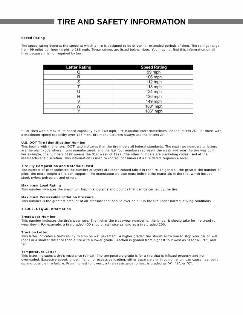
Speed Rating
The speed rating denotes the speed at which a tire is designed to be driven for extended periods of time. The ratings rangefrom 99 miles per hour (mph) to 186 mph. These ratings are listed below. Note: You may not find this information on alltires because it is not required by law.
* For tires with a maximum speed capability over 149 mph, tire manufacturers sometimes use the letters ZR. For those witha maximum speed capability over 186 mph, tire manufacturers always use the letters ZR.
U.S. DOT Tire Identification NumberThis begins with the letters "DOT" and indicates that the tire meets all federal standards. The next two numbers or lettersare the plant code where it was manufactured, and the last four numbers represent the week and year the tire was built.For example, the numbers 3197 means the 31st week of 1997. The other numbers are marketing codes used at themanufacturer's discretion. This information is used to contact consumers if a tire defect requires a recall.
Tire Ply Composition and Materials UsedThe number of plies indicates the number of layers of rubber-coated fabric in the tire. In general, the greater the number ofplies, the more weight a tire can support. Tire manufacturers also must indicate the materials in the tire, which includesteel, nylon, polyester, and others.
Maximum Load RatingThis number indicates the maximum load in kilograms and pounds that can be carried by the tire.
Maximum Permissible Inflation PressureThis number is the greatest amount of air pressure that should ever be put in the tire under normal driving conditions.
1.5.9.2. UTQGS Information
Treadwear NumberThis number indicates the tire's wear rate. The higher the treadwear number is, the longer it should take for the tread towear down. For example, a tire graded 400 should last twice as long as a tire graded 200.
Traction LetterThis letter indicates a tire's ability to stop on wet pavement. A higher graded tire should allow you to stop your car on wetroads in a shorter distance than a tire with a lower grade. Traction is graded from highest to lowest as "AA","A", "B", and"C".
Temperature LetterThis letter indicates a tire's resistance to heat. The temperature grade is for a tire that is inflated properly and notoverloaded. Excessive speed, underinflation or excessive loading, either separately or in combination, can cause heat build-up and possible tire failure. From highest to lowest, a tire's resistance to heat is graded as "A", "B", or "C".

1.5.9.3. Additional Information on Light Truck Tires
Please refer to the following diagram.
TIRE AND SAFETY INFORMATION
Tires for light trucks have other markings besides those found on the sidewalls of passenger tires.
LTThe "LT" indicates the tire is for light trucks or trailers.
STAn "ST" is an indication the tire is for trailer use only.
Max. Load Dual kg (lbs) at kPa (psi) ColdThis information indicates the maximum load and tire pressure when the tire is used as a dual, that is, when four tires areput on each rear axle (a total of six or more tires on the vehicle).
Max. Load Single kg (lbs) at kPa (psi) ColdThis information indicates the maximum load and tire pressure when the tire is used as a single.
Load RangeThis information identifies the tire's load-carrying capabilities and its inflation limits.
1.6. Tire Safety Tips
Preventing Tire Damage
- Slow down if you have to go over a pothole or other object in the road. - Do not run over curbs or other foreign objects in the roadway, and try not to strike the curb when parking.
Tire Safety Checklist
- Check tire pressure regularly (at least once a month), including the spare. - Inspect tires for uneven wear patterns on the tread, cracks, foreign objects, or other signs of wear or trauma. - Remove bits of glass and foreign objects wedged in the tread. - Make sure your tire valves have valve caps. - Check tire pressure before going on a long trip. - Do not overload your vehicle. Check the Tire Information and Loading Placard or User’s Manual for the maximumrecommended load for the vehicle.

Towmaster Trailers Product Manual
41
SECTION V
Maintenance
Parts Contact Information
Vendor Information
43
44
45
…...................
…...................
…...................
Towmaster Trailers Product Manual
42
Towmaster Trailers Product Manual
43
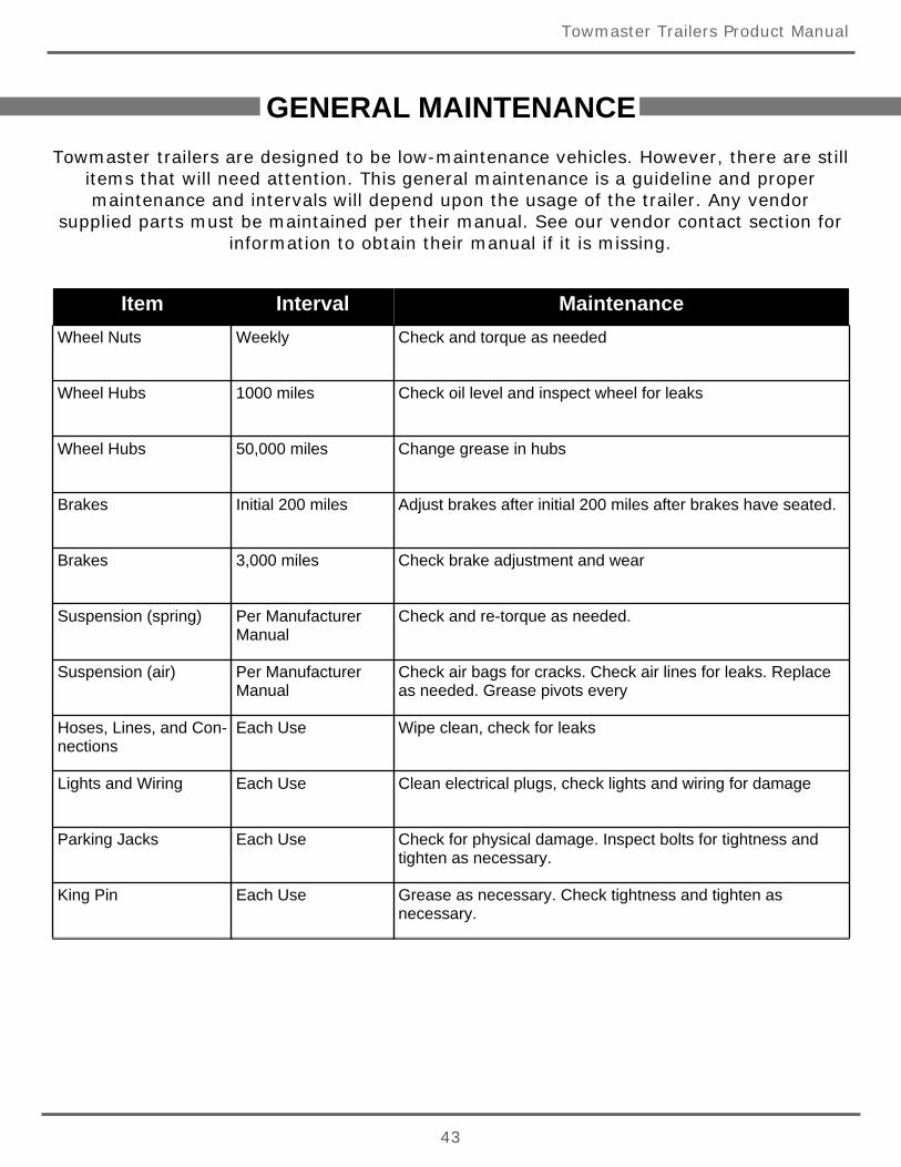
GENERAL MAINTENANCETowmaster trailers are designed to be low-maintenance vehicles. However, there are still
items that will need attention. This general maintenance is a guideline and propermaintenance and intervals will depend upon the usage of the trailer. Any vendor
supplied parts must be maintained per their manual. See our vendor contact section forinformation to obtain their manual if it is missing.
Item Interval MaintenanceWheel Nuts Weekly Check and torque as needed
Wheel Hubs 1000 miles Check oil level and inspect wheel for leaks
Wheel Hubs 50,000 miles Change grease in hubs
Brakes Initial 200 miles Adjust brakes after initial 200 miles after brakes have seated.
Brakes 3,000 miles Check brake adjustment and wear
Suspension (spring) Per ManufacturerManual
Check and re-torque as needed.
Suspension (air) Per ManufacturerManual
Check air bags for cracks. Check air lines for leaks. Replaceas needed. Grease pivots every
Hoses, Lines, and Con-nections
Each Use Wipe clean, check for leaks
Lights and Wiring Each Use Clean electrical plugs, check lights and wiring for damage
Parking Jacks Each Use Check for physical damage. Inspect bolts for tightness andtighten as necessary.
King Pin Each Use Grease as necessary. Check tightness and tighten asnecessary.
Towmaster Trailers Product Manual
44
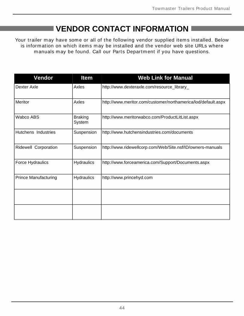
VENDOR CONTACT INFORMATIONYour trailer may have some or all of the following vendor supplied items installed. Below
is information on which items may be installed and the vendor web site URLs wheremanuals may be found. Call our Parts Department if you have questions.
Vendor Item Web Link for ManualDexter Axle Axles http://www.dexteraxle.com/resource_library_
Meritor Axles http://www.meritor.com/customer/northamerica/lod/default.aspx
Wabco ABS BrakingSystem
http://www.meritorwabco.com/ProductLitList.aspx
Hutchens Industries Suspension http://www.hutchensindustries.com/documents
Ridewell Corporation Suspension http://www.ridewellcorp.com/Web/Site.nsf/ID/owners-manuals
Force Hydraulics Hydraulics http://www.forceamerica.com/Support/Documents.aspx
Prince Manufacturing Hydraulics http://www.princehyd.com
Towmaster Trailers Product Manual
45
PARTS CONTACTTowmaster trailer dealers may have many of the replacement parts in stock. You canalso purchase replacement items from the Towmaster Parts Store. Some items are
available for purchase online while others are only available by calling our Parts Store.
Towmaster Parts Store
61381 US Hwy 12
Litchfield, MN 55355
320-593-4595
http://shop.towmaster.com


61381 U.S. Hwy 12
Litchfield, MN 55355
Parts Dept: 320-593-4595
towmaster.com
Operations and Service Manual—Hydraulic Tail—1012


