90
Crestron DVPHD High Definition Digital Video Processor Operations Guide
Crestron DVPHD High Definition Digital Video Processor Operations Guide
The specific patents that cover Crestron products are listed at patents.crestron.com. Crestron, the Crestron logo, Cresnet, Crestron e-Control, Crestron Studio, Crestron Toolbox, DigitalMedia, DM, QuickMedia, QuickSwitch HD, Synapse, V-Panel, and VT Pro-e are either trademarks or registered trademarks of Crestron Electronics, Inc. in the United States and/or other countries. 3M and MicroTouch are either trademarks or registered trademarks of 3M Company in the United States and/or other countries. AU Optronics is either a trademark or registered trademark of AU Optronics Corp in the United States and/or other countries. Blu-ray Disc is either a trademark or registered trademark of the Blu-ray Disc Association (BDA) in the United States and/or other countries. Compaq is either a trademark or registered trademark of Compaq Trademark B. V. in the United States and/or other countries. Elo Touch Solutions is either a trademark or registered trademark of Elo Touch Solutions, Inc. in the United States and/or other countries. HDMI and the HDMI logo are either trademarks or registered trademarks of HDMI Licensing LLC in the United States and/or other countries. HP is either a trademark or registered trademark of Hewlett-Packard Development Company L. P. and HPQ Holdings, LLC in the United States and/or other countries. Hatteland is either a trademark or registered trademark of Jakob Hattleland Display AS in the United States and/or other countries. Kristel is either a trademark or registered trademark of Kristel Limited Partnership in the United States and/or other countries. LG is either a trademark or registered trademark of LG Electronics in the United States and/or other countries. NEC is either a trademark or registered trademark of NEC Corporation in the United States and/or other countries. NextWindow is either a trademark or registered trademark of Next Holdings Limited in the United States and/or other countries. Planar is either a trademark or registered trademark of Planar Systems, Inc. in the United States and/or other countries. Canvys is either a trademark or registered trademark of Richardson Electronics, Inc. in the United States and/or other countries. Samsung is either a trademark or registered trademark of Samsung Electronics Co. Ltd. in the United States and/or other countries. Compact Flash is either a trademark or registered trademark of SanDisk Corporation in the United States and/or other countries. VXP and the VXP logo are either trademarks or registered trademarks of Sigma Designs Inc. in the United States and/or other countries. TouchTable is either a trademark or registered trademark of TouchTable Inc. in the United States and/or other countries. CyberTouch is either a trademark or registered trademark of Transparent Devices Inc. in the United States and/or other countries. ViewSonic is either a trademark or registered trademark of ViewSonic Corporation in the United States and/or other countries. Wacom is either a trademark or registered trademark of Wacom Co. Ltd. in the United States and/or other countries. Other trademarks, registered trademarks, and trade names may be used in this document to refer to either the entities claiming the marks and names or their products. Crestron disclaims any proprietary interest in the marks and names of others. Crestron is not responsible for errors in typography or photography. This document was written by the Technical Publications department at Crestron. ©2013 Crestron Electronics, Inc.
Regulatory Compliance As of the date of manufacture, the DVPHD has been tested and found to comply with specifications for CE marking and standards per EMC and Radiocommunications Compliance Labelling.
Federal Communications Commission (FCC) Compliance Statement This device complies with part 15 of the FCC Rules. Operation is subject to the following conditions: (1) This device may not cause harmful interference and (2) this device must accept any interference received, including interference that may cause undesired operation.
CAUTION: Changes or modifications not expressly approved by the manufacturer responsible for compliance could void the user’s authority to operate the equipment.
NOTE: This equipment has been tested and found to comply with the limits for a Class B digital device, pursuant to part 15 of the FCC Rules. These limits are designed to provide reasonable protection against harmful interference in a residential installation. This equipment generates, uses and can radiate radio frequency energy and, if not installed and used in accordance with the instructions, may cause harmful interference to radio communications. However, there is no guarantee that interference will not occur in a particular installation. If this equipment does cause harmful interference to radio or television reception, which can be determined by turning the equipment off and on, the user is encouraged to try to correct the interference by one or more of the following measures:
• Reorient or relocate the receiving antenna
• Increase the separation between the equipment and receiver
• Connect the equipment into an outlet on a circuit different from that to which the receiver is connected
• Consult the dealer or an experienced radio/TV technician for help
Industry Canada (IC) Compliance Statement CAN ICES-3(B)/NMB-3(B)
Crestron DVPHD High Definition Digital Video Processor
Operations Guide – DOC. 6545F Contents • i
Contents
High Definition Digital Video Processor: DVPHD 1
Introduction ............................................................................................................................... 1 Features and Functions ................................................................................................ 1 Specifications .............................................................................................................. 7 Physical Description .................................................................................................. 10
Setup ........................................................................................................................................ 15 Network Wiring ......................................................................................................... 15 Identity Code ............................................................................................................. 15 Video Processor Configuration ................................................................................. 16 Installation ................................................................................................................. 40 Hardware Hookup ..................................................................................................... 42
Uploading and Upgrading ........................................................................................................ 44 Establishing Communication ..................................................................................... 44 Programs, Projects and Firmware .............................................................................. 46 Program Checks ........................................................................................................ 46
Operation ................................................................................................................................. 48 VIDEO INPUTS ........................................................................................................ 50 QM SETUP ............................................................................................................... 54 DISPLAY OUTPUT ................................................................................................. 57 ETHERNET .............................................................................................................. 59 CONTROL ................................................................................................................ 62 QUICK OOTBF CONFIG ........................................................................................ 79 ENTER/EXIT SETUP ............................................................................................... 80
Problem Solving ...................................................................................................................... 81 Troubleshooting ......................................................................................................... 81 Check Network Wiring .............................................................................................. 82 Reference Documents ................................................................................................ 83 Further Inquiries ........................................................................................................ 83 Future Updates .......................................................................................................... 83
Return and Warranty Policies .................................................................................................. 84 Merchandise Returns / Repair Service ...................................................................... 84 Crestron Limited Warranty ........................................................................................ 84


Crestron DVPHD High Definition Digital Video Processor
Operations Guide – DOC. 6545F High Definition Digital Video Processor: DVPHD • 1
• The first multiwindow video presentation processor available that supports HD video with HDCP
• Displays up to eight fully scalable video windows • Features VXP® high definition scaling and deinterlacing • Modular design accepts the choice of up to eight simultaneous inputs1 • Handles HDMI®, DVI, DisplayPort Multimode, and HD-SDI digital
video sources2 • Handles analog RGB, component, S-video, and composite video
sources2
High Definition Digital Video Processor: DVPHD
Introduction Envision a world class multimedia presentation system for a boardroom, auditorium, command center, home theater, or house of worship. Picture all the video and computer resources in a system displayed in perfect harmony and clarity within a dramatic graphical environment all on one high definition screen. Imagine the ability to seamlessly control the presentation and annotate ideas with a stroke of a finger.
That is the DVPHD High Definition Digital Video Processor from Crestron®, the world’s only multiwindow video processor that displays high res computer and high definition video signals with HDCP, provides a fully customizable HD graphics environment and enables real time annotation and touch screen control, all in a modular, scalable hardware platform that is easy to install.
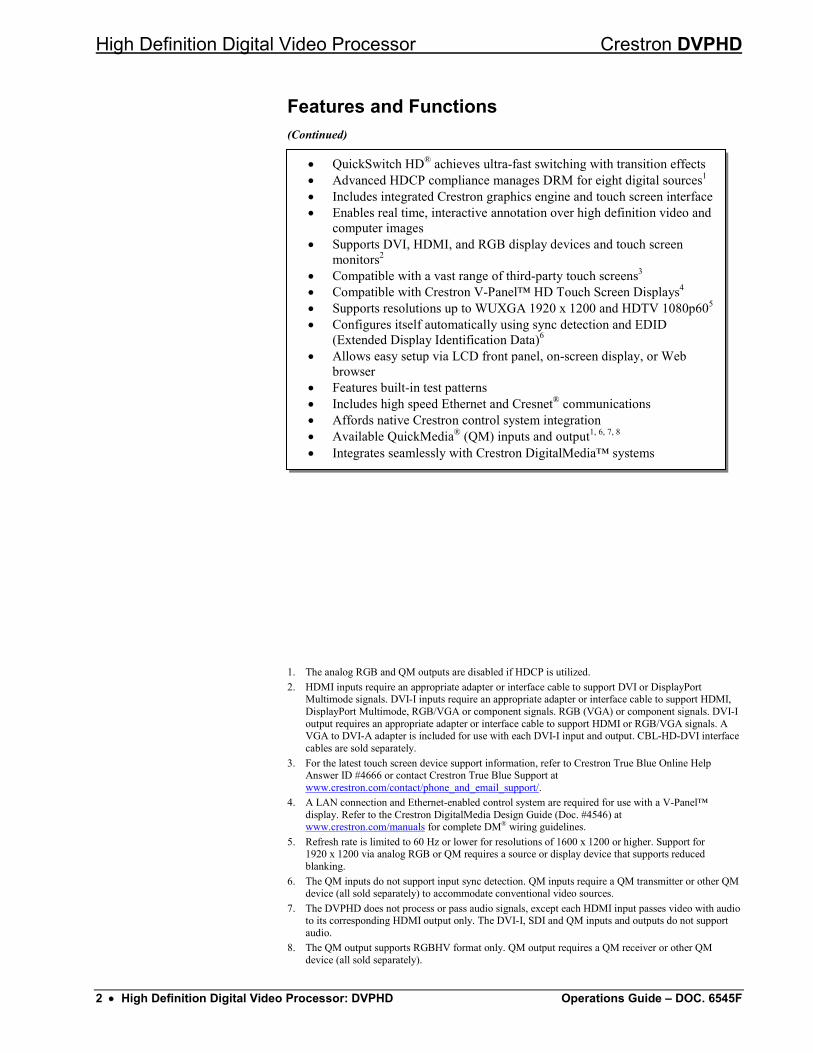
Features and Functions
(Continued on following page)
1. Actual signal types and quantities are dependent on the on the selected input/output card configuration. To configure a DVPHD with input and output cards, please select one of the pre-configured models or use the online DVPHD Configuration Tool at www.crestron.com/resources/system_design_resources/product_configuration_tools/dvphd/ to configure a custom model. All input and output cards must be factory installed.
2. HDMI inputs require an appropriate adapter or interface cable to support DVI or DisplayPort Multimode signals. DVI-I inputs require an appropriate adapter or interface cable to support HDMI, DisplayPort Multimode, RGB/VGA, or component signals. RGB (VGA) or component signals. DVI-I output requires an appropriate adapter or interface cable to support HDMI or RGB/VGA signals. A VGA to DVI-A adapter is included for use with each DVI-I input and output. CBL-HD-DVI interface cables are sold separately.
High Definition Digital Video Processor Crestron DVPHD
2 • High Definition Digital Video Processor: DVPHD Operations Guide – DOC. 6545F
• QuickSwitch HD® achieves ultra-fast switching with transition effects • Advanced HDCP compliance manages DRM for eight digital sources1 • Includes integrated Crestron graphics engine and touch screen interface • Enables real time, interactive annotation over high definition video and
computer images • Supports DVI, HDMI, and RGB display devices and touch screen
monitors2 • Compatible with a vast range of third-party touch screens3 • Compatible with Crestron V-Panel™ HD Touch Screen Displays4 • Supports resolutions up to WUXGA 1920 x 1200 and HDTV 1080p605 • Configures itself automatically using sync detection and EDID
(Extended Display Identification Data)6 • Allows easy setup via LCD front panel, on-screen display, or Web
browser • Features built-in test patterns • Includes high speed Ethernet and Cresnet® communications • Affords native Crestron control system integration • Available QuickMedia® (QM) inputs and output1, 6, 7, 8 • Integrates seamlessly with Crestron DigitalMedia™ systems
Features and Functions (Continued)
1. The analog RGB and QM outputs are disabled if HDCP is utilized. 2. HDMI inputs require an appropriate adapter or interface cable to support DVI or DisplayPort
Multimode signals. DVI-I inputs require an appropriate adapter or interface cable to support HDMI, DisplayPort Multimode, RGB/VGA or component signals. RGB (VGA) or component signals. DVI-I output requires an appropriate adapter or interface cable to support HDMI or RGB/VGA signals. A VGA to DVI-A adapter is included for use with each DVI-I input and output. CBL-HD-DVI interface cables are sold separately.
3. For the latest touch screen device support information, refer to Crestron True Blue Online Help Answer ID #4666 or contact Crestron True Blue Support at www.crestron.com/contact/phone_and_email_support/.
4. A LAN connection and Ethernet-enabled control system are required for use with a V-Panel™ display. Refer to the Crestron DigitalMedia Design Guide (Doc. #4546) at www.crestron.com/manuals for complete DM® wiring guidelines.
5. Refresh rate is limited to 60 Hz or lower for resolutions of 1600 x 1200 or higher. Support for 1920 x 1200 via analog RGB or QM requires a source or display device that supports reduced blanking.
6. The QM inputs do not support input sync detection. QM inputs require a QM transmitter or other QM device (all sold separately) to accommodate conventional video sources.
7. The DVPHD does not process or pass audio signals, except each HDMI input passes video with audio to its corresponding HDMI output only. The DVI-I, SDI and QM inputs and outputs do not support audio.
8. The QM output supports RGBHV format only. QM output requires a QM receiver or other QM device (all sold separately).
Crestron DVPHD High Definition Digital Video Processor
Operations Guide – DOC. 6545F High Definition Digital Video Processor: DVPHD • 3
The DVPHD is configurable to handle up to eight different inputs of virtually any type, including HDMI®, DVI, DisplayPort (Multimode), HD-SDI, and analog signals.1, 2 Industry leading support for HDCP ensures compatibility with content protected DVD, Blu-ray Disc™, digital HDTV, and multimedia computer sources. Advanced high definition image processing achieves astounding realism and detail for every input signal, with the ability to display up to eight separate video images at once, or switch fluently between them using alluring digital transition effects and customizable graphics.
Multiwindow Video Processor The DVPHD displays up to eight simultaneous, full motion video windows3 on any high resolution monitor, projector or flat panel display. The video windows can be displayed on screen in any combination, with enhanced dynamic text capabilities for labeling each window. Video images can even fade or fly in and out over a personalized background using digital transition effects and customizable graphics, lending enhanced flow and vibe to the total presentation. Each window is fully scalable and independently controllable, allowing for display at any position, size or aspect ratio.
QuickSwitch HD Crestron exclusive QuickSwitch HD technology eliminates the annoying latency and blanking that plagues other digital switchers and video processors. Switching between inputs of any type is fast and fluid on the DVPHD.
Advanced Image Processing On any size display, whether viewing a full screen image or multiple windows with graphics, the DVPHD scales its output perfectly to match the display’s native resolution and aspect ratio. VXP® video processing with fully adaptive deinterlacing achieves exceptional realism and rich detail from standard definition, high definition and computer sources.
Customizable Graphics Besides displaying video and computer images, the DVPHD includes our 24-bit graphics engine with alpha transparency for creating dramatic visual effects and conveying all kinds of useful data. Use a choice of background textures, full color images, logos, and other design elements to create the perfect look and feel for the application. Use dynamic graphics and text, crawling text, pop-up windows, animations, and multimode objects to deliver a message with clarity and style.
1. Actual signal types and quantities are dependent on the on the selected input/output card
configuration. To configure a DVPHD with input and output cards, please select one of the pre-configured models or use the online DVPHD Configuration Tool at www.crestron.com/resources/system_design_resources/product_configuration_tools/dvphd/ to configure a custom model. All input and output cards must be factory installed.
2. HDMI inputs require an appropriate adapter or interface cable to support DVI or DisplayPort Multimode signals. DVI-I inputs require an appropriate adapter or interface cable to support HDMI, DisplayPort Multimode, RGB/VGA or component signals. RGB (VGA) or component signals. DVI-I output requires an appropriate adapter or interface cable to support HDMI or RGB/VGA signals. A VGA to DVI-A adapter is included for use with each DVI-I input and output. CBL-HD-DVI interface cables are sold separately.
3. Each video window is fed by a dedicated input and the quantity of windows is limited to the quantity of inputs. While it is possible to dynamically select which input appears in a single window, it is not possible to view a single input in more than one window at a time.
High Definition Digital Video Processor Crestron DVPHD
4 • High Definition Digital Video Processor: DVPHD Operations Guide – DOC. 6545F
HDCP Management The DVPHD is the first multiwindow video processor of its kind that handles HDCP (High-bandwidth Digital Content Protection) to work with a complete range of digital video players, cable and satellite receivers, multimedia computers, displays and projectors, now and into the future. While other manufacturers ignore HDCP completely, the DVPHD actually performs advanced HDCP signal management, allowing up to eight HDCP encrypted sources to be combined on one high definition screen.
Touch Screen Interface The DVPHD can transform a third-party touch screen monitor, pen display, whiteboard, or touch-enabled flat panel display into a full featured, large scale Crestron touch screen.1 This opens a host of possibilities for special control and presentation applications such as interactive kiosks, museum and tradeshow exhibits, training rooms, and command centers. Employing Crestron DNav technology, the DVPHD lets users scroll effortlessly through menus and toolbars with a natural sweep of the finger to select from lists of touch screen apps, media titles and more.
As an alternative to a touch screen, the graphical interface can also be navigated using an on-screen cursor driven by a wired or wireless mouse or by discrete commands from a separate touch screen, computer, keypad or handheld remote.
Vast Touch Screen Support The DVPHD is compatible with more touch screen displays than any other touch screen interface on the market. Many dozens of models are supported from numerous manufacturers with more being added all the time. With a vast array of sizes available, in a variety of tabletop, flush mount, and other specialized configurations, there is sure to be a solution that is perfect for any custom application.1
V-Panel Integration A Creston V-Panel™ display works impeccably with the DVPHD to deliver a very stylish and flexible high definition touch screen solution for a range of uses. The V-Panel display connects to the output of the DVPHD via a DigitalMedia™ transmitter or switcher (both sold separately), affording a very streamlined single-wire interface to the V-Panel up to 450 feet (137 meters) away.2
HD Annotation Only Crestron allows annotation in real time over any high definition video image. Whether conducting a boardroom meeting, training seminar, or classroom lecture, annotation helps put the fine point on any presentation. In combination with a touch screen display, the DVPHD provides the essential annotation tools to make a point with maximum impact, letting the user illustrate their thoughts over video and computer sources, and sketch out ideas on a whiteboard screen, easily and intuitively. Brush sizes and colors are selectable on the fly for ultimate clarity. Moving images can be frozen on screen to allow pinpoint annotation over a still picture. Annotation over two or more different sources at once is possible, for easy side by side comparison of multiple related images.
1. For the latest touch screen device support information, refer to Crestron True Blue Online Help
Answer ID #4666 or contact Crestron True Blue Support. 2. A LAN connection and Ethernet-enabled control system are required for use with a V-Panel display.
Refer to the Crestron DigitalMedia Design Guide, Doc. #4546 for complete DM wiring guidelines.

Crestron DVPHD High Definition Digital Video Processor
Operations Guide – DOC. 6545F High Definition Digital Video Processor: DVPHD • 5
Interactive Annotation Crestron exclusive Remote Annotation capability lets up to 90 individual touch screen users “mass annotate” over the same image, supporting efficient and effective interaction between participants in a classroom, courtroom, council chamber, operating room, or command center.
Multiformat Support The DVPHD is custom configurable to accommodate a full range of input signal types1. Any resolution up to 1920 x 12002 can be supported, with an incredible 125 pre-defined “standard” resolutions and the ability to define any custom resolution. Available inputs include:
• HDMI – Supports high definition digital video with HDCP and Deep Color. Handles resolutions up to HD 1080p60 or 1080i30 and WUXGA 1920 x 1200. Each HDMI input includes a complementary HDMI output to pass the incoming video and audio signals through to another HDMI device. HDMI inputs are also compatible with DVI and DisplayPort Multimode sources. The DVPHD can be configured with up to four HDMI inputs.3, 4
• DVI-I – Supports DVI digital video signals as well as RGB/VGA or component analog signals. Handles HDCP and Deep Color at resolutions up to 1080p60 and WUXGA. Also handles 1080i interlaced signals via analog. DVI is also compatible with HDMI and DisplayPort Multimode sources. The DVPHD can be configured with up to four DVI-I inputs.3, 4
• Multiformat BNC video – Supports analog component, S-video and composite video sources. Handles NTSC, PAL, and HD1080i interlaced signals as well as progressive signals up to 720p. The DVPHD can be configured with up to eight multiformat BNC video inputs.
• SDI – Supports SDI and HD-SDI digital video signals up to 1080i30 or 1080p30. The DVPHD can be configured with up to four SDI inputs.
• QuickMedia – Allows for direct connection to a Crestron QuickMedia® system.4, 5
1. Actual signal types and quantities are dependent on the on the selected input/output card
configuration. To configure a DVPHD with input and output cards, please select one of the pre-configured models or use the online DVPHD Configuration Tool at www.crestron.com/resources/system_design_resources/product_configuration_tools/dvphd/ to configure a custom model. All input and output cards must be factory installed.
2. Refresh rate is limited to 60 Hz or lower for resolutions of 1600 x 1200 or higher. Support for 1920 x 1200 via analog RGB or QM requires a source or display device that supports reduced blanking.
3. HDMI inputs require an appropriate adapter or interface cable to support DVI or DisplayPort Multimode signals. DVI-I inputs require an appropriate adapter or interface cable to support HDMI, DisplayPort Multimode, RGB/VGA or component signals. RGB (VGA) or component signals. DVI-I output requires an appropriate adapter or interface cable to support HDMI or RGB/VGA signals. A VGA to DVI-A adapter is included for use with each DVI-I input and output. CBL-HD-DVI interface cables are sold separately.
4. The DVPHD does not process or pass audio signals, except each HDMI input passes video with audio to its corresponding HDMI output only. The DVI-I, SDI and QM inputs and outputs do not support audio.
5. The QM inputs do not support input sync detection. QM inputs require a QM transmitter or other QM device (all sold separately) to accommodate conventional video sources.
High Definition Digital Video Processor Crestron DVPHD
6 • High Definition Digital Video Processor: DVPHD Operations Guide – DOC. 6545F
HD Display Output Through its DVI-I output, the DVPHD can handle virtually any display device, providing a DVI, HDMI, or analog RGB signal at any resolution up to 1920 x 1200. Interlaced 1080i output is also supported via DVI or HDMI only. A QM output is included, allowing easy extension of the RGB output signal to feed a display device up to 450 feet (137 meters) away.1, 2, 3, 4, 5
Auto-Configuration The DVPHD is easy to install, configuring itself automatically to match all the different sources and displays as they are connected. Input sync detection sets the optimum format, resolution, and scan rate for each source6, while EDID (Extended Display Identification Data) adapts the output to match the connected display device. Manual adjustments and built-in test patterns are also available to allow fine adjustment of every input and output when desired.
Installer Friendly Setup Whether testing a new install or setting up for final operation, the DVPHD provides several easy methods for accessing all the essential controls and settings. On-screen setup is available right from the main output, navigable using a touch screen or mouse. The onboard Web server affords an alternate setup option, allowing for secure configuration and operation from any location using an ordinary Web browser on a networked computer. Setup can even be attained right from the front panel using the large LCD display.
Right out of the box, the DVPHD provides several display scenarios to choose from, with the ability to define a fully working setup in minutes. Built-in test patterns eliminate the need for an external pattern generator for proper display calibration. Advanced functionality and appearance is afforded through custom programming using the Crestron suite of software solutions.
Unparalleled System Integration Both Cresnet® and high speed Ethernet are standard on the DVPHD, providing full connectivity and seamless communication with one or more Crestron control systems to deliver the ultimate in system integration and advanced presentation control. The DVPHD is also well suited for integration with DigitalMedia systems, allowing for even greater input expansion and distribution to multiple displays.
1. HDMI inputs require an appropriate adapter or interface cable to support DVI or DisplayPort Multimode signals. DVI-I inputs require an appropriate adapter or interface cable to support HDMI, DisplayPort Multimode, RGB/VGA or component signals. RGB (VGA) or component signals. DVI-I output requires an appropriate adapter or interface cable to support HDMI or RGB/VGA signals. A VGA to DVI-A adapter is included for use with each DVI-I input and output. CBL-HD-DVI interface cables are sold separately.
2. Refresh rate is limited to 60 Hz or lower for resolutions of 1600 x 1200 or higher. Support for 1920 x 1200 via analog RGB or QM requires a source or display device that supports reduced blanking.
3. The DVPHD does not process or pass audio signals, except each HDMI input passes video with audio to its corresponding HDMI output only. The DVI-I, SDI and QM inputs and outputs do not support audio.
4. The QM output supports RGBHV format only. QM output requires a QM receiver or other QM device (all sold separately).
5. The analog RGB and QM outputs are disabled if HDCP is utilized. 6. The QM inputs do not support input sync detection. QM inputs require a QM transmitter or other QM
device (all sold separately) to accommodate conventional video sources.

Crestron DVPHD High Definition Digital Video Processor
Operations Guide – DOC. 6545F High Definition Digital Video Processor: DVPHD • 7
Specifications Specifications for the DVPHD are listed in the following table.
DVPHD Specifications
SPECIFICATION DETAILS Video
Scaling/Windowing Processor VXP video processing, 8-channel image processing, resolution management, QuickSwitch HD technology
Input Signal Types1 Auto-detecting DVI, HDMI, DisplayPort Multimode2, SDI, RGB, component (YPbPr), S-video (Y/C), composite, QuickMedia
Input Formats HDMI with Deep Color, DVI, HDCP content protection support, SDI, HD-SDI, computer up to UXGA/WUXGA, HD up to 1080i and 1080p60, NTSC or PAL
Input Resolutions, Progressive 640 x 400 to 1920 x 1200, 480p, 576p, 720p, 1080p3
Input Resolutions, Interlaced 480i, 487i (SDI), 576i, 1080i Output Signal Types DVI, HDMI, RGB, QuickMedia2, 4, 5 Output Formats DVI, HDMI with Deep Color, HDCP content
protection support, computer up to UXGA/WUXGA, HD progressive up to 1080p60, HDTV interlaced @ 1080i only
Output Resolutions, Progressive
640 x 400 to 1920 x 1200, 480p, 576p, 720p, 1080p3
Output Resolutions, Interlaced 1080i via DVI or HDMI only Color Depth 24-bit, 16.7 million colors Analog Gain 0 dB (75 Ω terminated) Analog Bandwidth 400 MHz
Graphics Engine 24-bit color depth (non-palette), 8-bit alpha channel transparency, 16.7 million colors, Synapse™ image rendering algorithm, multimode objects, DNav dynamic menu objects, dynamic graphics, crawling text, PNG translucency, full motion (60 fps) animation, transition effects, color key video windowing, real time and remote annotation
Memory DDR RAM 256 MB Flash 64 MB Compact Flash® Accepts up to 4 GB (1 GB Type II Compact
Flash card included) Maximum Project Size 200 MB
(Continued on following page)
High Definition Digital Video Processor Crestron DVPHD
8 • High Definition Digital Video Processor: DVPHD Operations Guide – DOC. 6545F
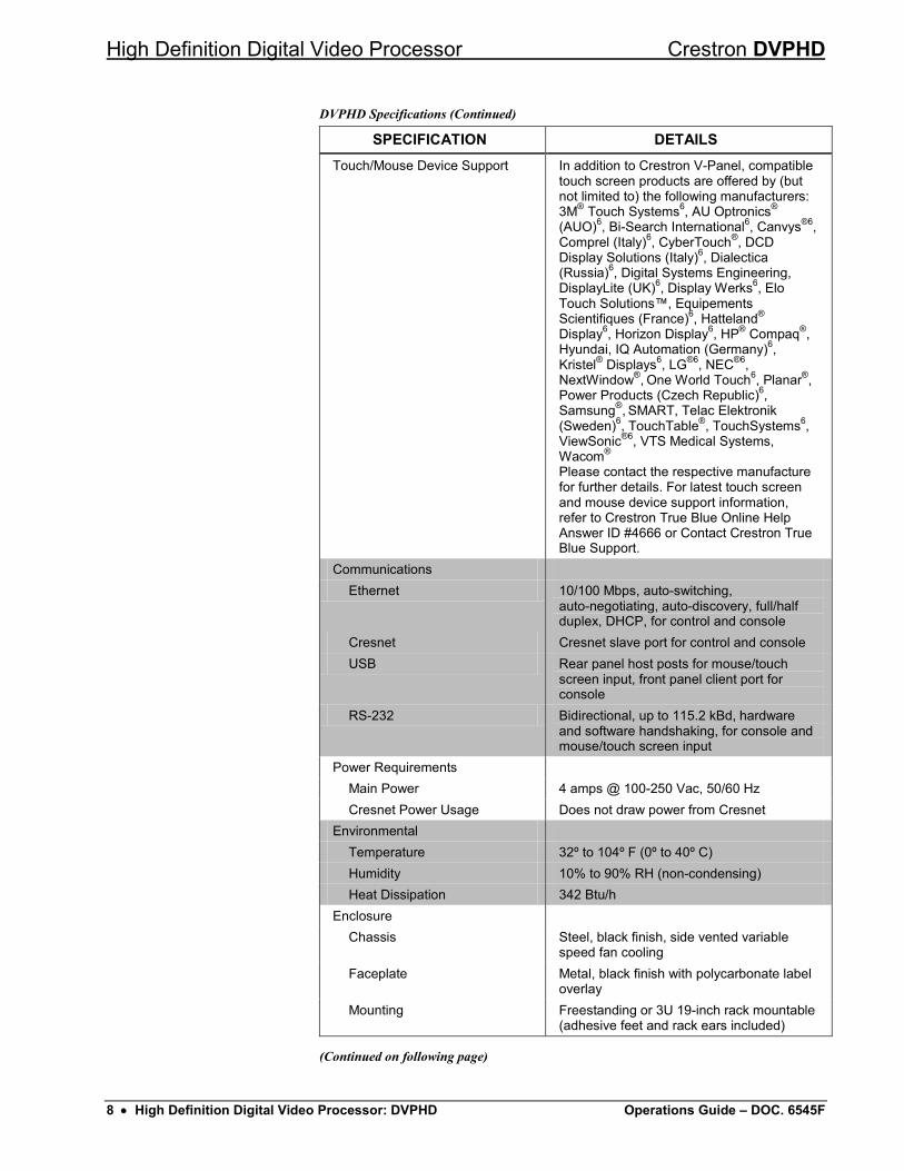
DVPHD Specifications (Continued)
SPECIFICATION DETAILS Touch/Mouse Device Support In addition to Crestron V-Panel, compatible
touch screen products are offered by (but not limited to) the following manufacturers: 3M® Touch Systems6, AU Optronics® (AUO)6, Bi-Search International6, Canvys®6, Comprel (Italy)6, CyberTouch®, DCD Display Solutions (Italy)6, Dialectica (Russia)6, Digital Systems Engineering, DisplayLite (UK)6, Display Werks6, Elo Touch Solutions™, Equipements Scientifiques (France)6, Hatteland® Display6, Horizon Display6, HP® Compaq®, Hyundai, IQ Automation (Germany)6, Kristel® Displays6, LG®6, NEC®6, NextWindow®, One World Touch6, Planar®, Power Products (Czech Republic)6, Samsung®, SMART, Telac Elektronik (Sweden)6, TouchTable®, TouchSystems6, ViewSonic®6, VTS Medical Systems, Wacom® Please contact the respective manufacture for further details. For latest touch screen and mouse device support information, refer to Crestron True Blue Online Help Answer ID #4666 or Contact Crestron True Blue Support.
Communications Ethernet 10/100 Mbps, auto-switching,
auto-negotiating, auto-discovery, full/half duplex, DHCP, for control and console
Cresnet Cresnet slave port for control and console USB Rear panel host posts for mouse/touch
screen input, front panel client port for console
RS-232 Bidirectional, up to 115.2 kBd, hardware and software handshaking, for console and mouse/touch screen input
Power Requirements Main Power 4 amps @ 100-250 Vac, 50/60 Hz Cresnet Power Usage Does not draw power from Cresnet
Environmental Temperature 32º to 104º F (0º to 40º C) Humidity 10% to 90% RH (non-condensing) Heat Dissipation 342 Btu/h
Enclosure Chassis Steel, black finish, side vented variable
speed fan cooling Faceplate Metal, black finish with polycarbonate label
overlay Mounting Freestanding or 3U 19-inch rack mountable
(adhesive feet and rack ears included)
(Continued on following page)
Crestron DVPHD High Definition Digital Video Processor
Operations Guide – DOC. 6545F High Definition Digital Video Processor: DVPHD • 9
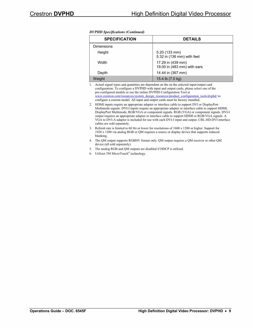
DVPHD Specifications (Continued)
SPECIFICATION DETAILS Dimensions
Height 5.20 (133 mm) 5.32 in (136 mm) with feet
Width 17.29 in (439 mm) 19.00 in (483 mm) with ears
Depth 14.44 in (367 mm) Weight 15.4 lb (7.0 kg)
1. Actual signal types and quantities are dependent on the on the selected input/output card configuration. To configure a DVPHD with input and output cards, please select one of the pre-configured models or use the online DVPHD Configuration Tool at www.crestron.com/resources/system_design_resources/product_configuration_tools/dvphd/ to configure a custom model. All input and output cards must be factory installed.
2. HDMI inputs require an appropriate adapter or interface cable to support DVI or DisplayPort Multimode signals. DVI-I inputs require an appropriate adapter or interface cable to support HDMI, DisplayPort Multimode, RGB/VGA or component signals. RGB (VGA) or component signals. DVI-I output requires an appropriate adapter or interface cable to support HDMI or RGB/VGA signals. A VGA to DVI-A adapter is included for use with each DVI-I input and output. CBL-HD-DVI interface cables are sold separately.
3. Refresh rate is limited to 60 Hz or lower for resolutions of 1600 x 1200 or higher. Support for 1920 x 1200 via analog RGB or QM requires a source or display device that supports reduced blanking.
4. The QM output supports RGBHV format only. QM output requires a QM receiver or other QM device (all sold separately).
5. The analog RGB and QM outputs are disabled if HDCP is utilized. 6. Utilizes 3M MicroTouch® technology.

High Definition Digital Video Processor Crestron DVPHD
10 • High Definition Digital Video Processor: DVPHD Operations Guide – DOC. 6545F
Physical Description This section provides information on the connections, controls and indicators available on the DVPHD.
DVPHD Physical View (Front)
DVPHD Physical View (Rear)

Crestron DVPHD High Definition Digital Video Processor
Operations Guide – DOC. 6545F High Definition Digital Video Processor: DVPHD • 11
DVPHD Overall Dimensions (Front)
5.20 in(133 mm)
1 2 3 5
11
6 8 9
10
74
DVPHD Overall Dimensions (Top)
14.44 in(367 mm)
17.29 in(439 mm)
NOTE: Depth dimension includes maximum connector length of installed video input cards (not shown). Cable connections can extend the overall depth of the DVPHD by an additional 2 – 3 inches (51 – 76 mm).
High Definition Digital Video Processor Crestron DVPHD
12 • High Definition Digital Video Processor: DVPHD Operations Guide – DOC. 6545F
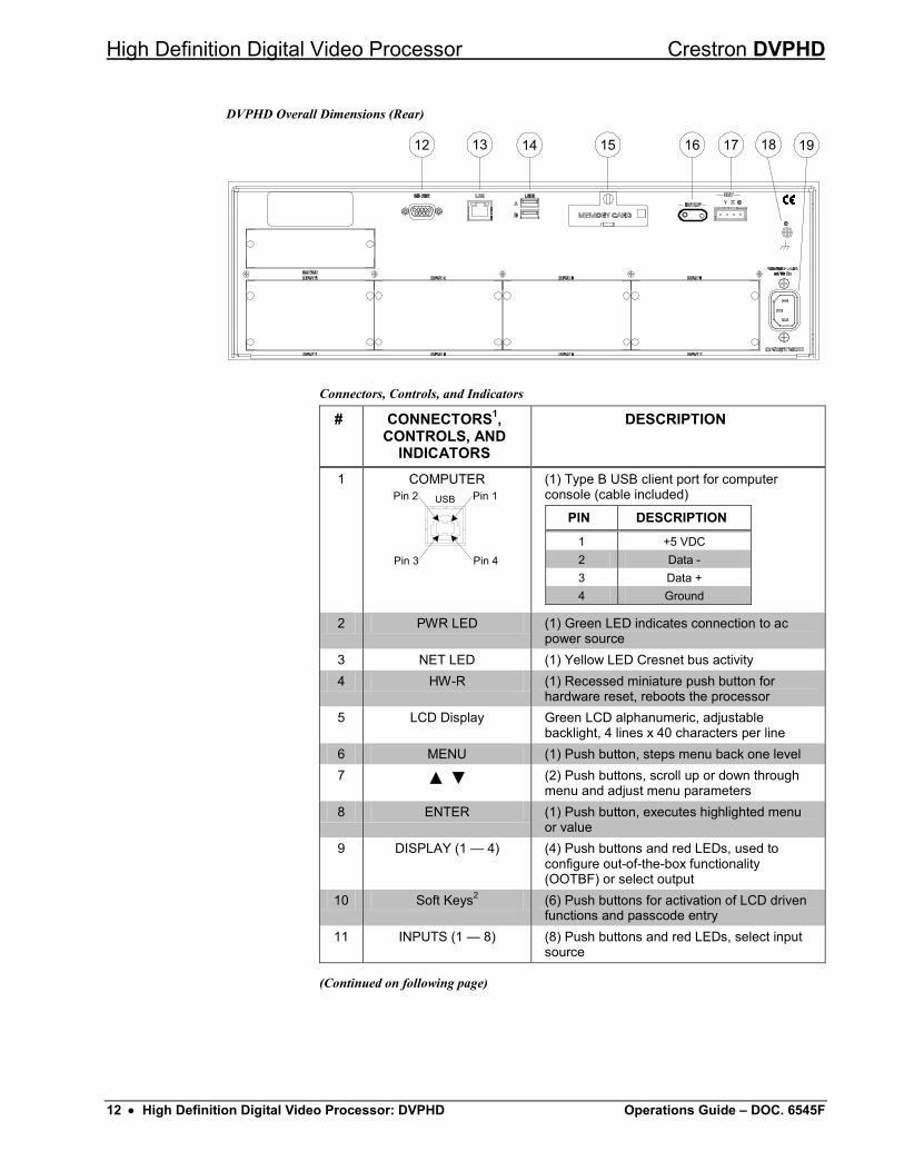
DVPHD Overall Dimensions (Rear)
12 13 14 15 16 17 18 19
Connectors, Controls, and Indicators
# CONNECTORS1, CONTROLS, AND
INDICATORS
DESCRIPTION
1 COMPUTER USBPin 2 Pin 1
Pin 3 Pin 4
(1) Type B USB client port for computer console (cable included)
PIN DESCRIPTION
1 +5 VDC 2 Data - 3 Data + 4 Ground
2 PWR LED (1) Green LED indicates connection to ac power source
3 NET LED (1) Yellow LED Cresnet bus activity 4 HW-R (1) Recessed miniature push button for
hardware reset, reboots the processor 5 LCD Display Green LCD alphanumeric, adjustable
backlight, 4 lines x 40 characters per line 6 MENU (1) Push button, steps menu back one level 7 (2) Push buttons, scroll up or down through
menu and adjust menu parameters 8 ENTER (1) Push button, executes highlighted menu
or value 9 DISPLAY (1 — 4) (4) Push buttons and red LEDs, used to
configure out-of-the-box functionality (OOTBF) or select output
10 Soft Keys2 (6) Push buttons for activation of LCD driven functions and passcode entry
11 INPUTS (1 — 8) (8) Push buttons and red LEDs, select input source
(Continued on following page)

Crestron DVPHD High Definition Digital Video Processor
Operations Guide – DOC. 6545F High Definition Digital Video Processor: DVPHD • 13
Connectors, Controls, and Indicators (Continued)
# CONNECTORS1, CONTROLS, AND
INDICATORS
DESCRIPTION
12 RS-2323
Pin 1
Pin 9
(1) DB9 female, bidirectional RS-232 port; Computer console and mouse/touch screen input3; Up to 115.2 kBd; hardware and software handshaking support
PIN # ABBREVIATION DESCRIPTION
2 TXD Transmit Data 3 RXD Receive Data 5 SG Signal Ground 7 CTS Clear To Send 8 RTS Request To
Send
13 LAN YellowLED
GreenLED
Pin 8 Pin 1
(1) 8-pin RJ-45 with 2 LED indicators; 10/100BASE-T Ethernet port for console and control; Green LED indicates link status; Yellow LED indicates Ethernet activity
PIN SIGNALS 1 TD+ 2 TD- 3 RD+ 4 Connected to pin 5 5 Connected to pin 4 6 RD- 7 Connected to pin 8 8 Connected to pin 7
14 USB (A – B)
Pins 1 2 3 4
(2) Type A USB 1.1 host ports for mouse or touch screen input
15 MEMORY CARD
(1) Compact Flash Type II card slot; For memory expansion up to 4 GB, 1 GB included
16 SETUP (Button and LED)
(1) Miniature push button and (1) red LED, used for TSID (Touch Settable ID) and Ethernet autodiscovery
17 NET Y Z G
(1) 4-pin 5 mm detachable terminal block; Cresnet slave port, connects to Cresnet control network Y: Data Z: Data G: Ground
18 G
(1) 6-32 screw, chassis ground lug
(Continued on following page)
High Definition Digital Video Processor Crestron DVPHD
14 • High Definition Digital Video Processor: DVPHD Operations Guide – DOC. 6545F
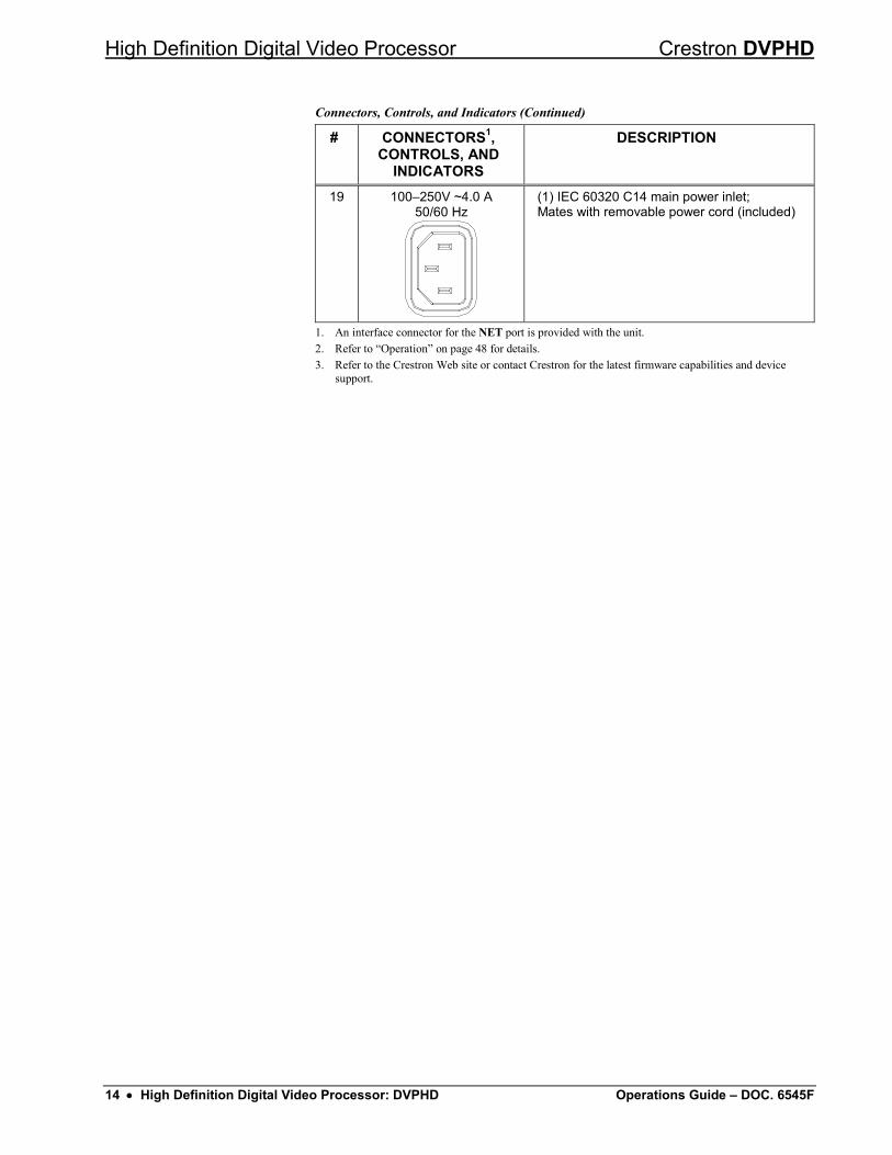
Connectors, Controls, and Indicators (Continued)
# CONNECTORS1, CONTROLS, AND
INDICATORS
DESCRIPTION
19 100–250V ~4.0 A 50/60 Hz
(1) IEC 60320 C14 main power inlet; Mates with removable power cord (included)
1. An interface connector for the NET port is provided with the unit. 2. Refer to “Operation” on page 48 for details. 3. Refer to the Crestron Web site or contact Crestron for the latest firmware capabilities and device
support.

Crestron DVPHD High Definition Digital Video Processor
Operations Guide – DOC. 6545F High Definition Digital Video Processor: DVPHD • 15
Setup
Network Wiring When wiring the Cresnet or Ethernet network, consider the following:
• Use Crestron Certified Wire.
• Use Crestron power supplies for Crestron equipment.
• Provide sufficient power to the system.
CAUTION: Insufficient power can lead to unpredictable results or damage to the equipment. Use the Crestron Power Calculator to help calculate how much power is needed for the system (www.crestron.com/calculators).
For Cresnet networks with 20 or more devices, use a Cresnet Hub/Repeater (CNXHUB) to maintain signal quality.
For more details, refer to “Check Network Wiring” on page 82.
The DVPHD can also use high-speed Ethernet for communications between the device and a control system, computer, media server and other IP-based devices.
For general information on connecting Ethernet devices in a Crestron system, refer to the Crestron e-Control Reference Guide (Doc. 6052) at www.crestron.com/manuals.
Identity Code NOTE: The latest software can be downloaded from the Crestron Web site (www.crestron.com/software).
Net ID The Net ID of the DVPHD has been factory set to 03. The Net IDs of multiple DVPHD devices in the same system must be unique. Net IDs are changed from a personal computer (PC) via the Crestron Toolbox™ (refer to “Establishing Communication” on page 44).
When setting the Net ID, consider the following:
• The Net ID of each unit must match an ID code specified in the Crestron Studio™ or SIMPL Windows program.
• Each network device must have a unique Net ID.
For more details, refer to the Crestron Toolbox help file.
IP ID The IP ID is set within the DVPHD’s IP table using Crestron Toolbox. For information on setting an IP table, refer to the Crestron Toolbox help file. The IP IDs of multiple DVPHD devices in the same system must be unique.
When setting the IP ID, consider the following:
• The IP ID of each unit must match an IP ID specified in the Crestron Studio or SIMPL Windows program.
• Each device using IP to communicate with a control system must have a unique IP ID.
High Definition Digital Video Processor Crestron DVPHD
16 • High Definition Digital Video Processor: DVPHD Operations Guide – DOC. 6545F
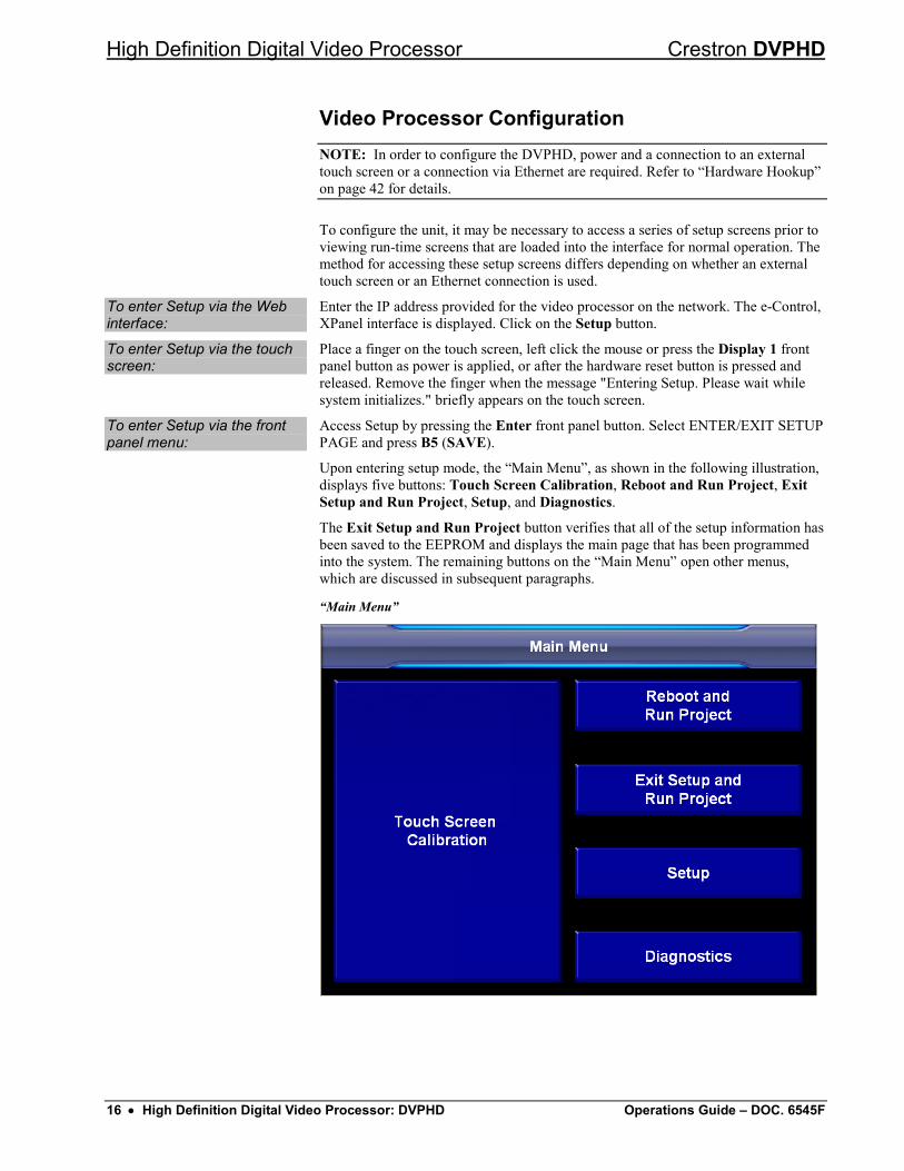
Video Processor Configuration NOTE: In order to configure the DVPHD, power and a connection to an external touch screen or a connection via Ethernet are required. Refer to “Hardware Hookup” on page 42 for details.
To configure the unit, it may be necessary to access a series of setup screens prior to viewing run-time screens that are loaded into the interface for normal operation. The method for accessing these setup screens differs depending on whether an external touch screen or an Ethernet connection is used.
To enter Setup via the Web interface:
Enter the IP address provided for the video processor on the network. The e-Control, XPanel interface is displayed. Click on the Setup button.
To enter Setup via the touch screen:
Place a finger on the touch screen, left click the mouse or press the Display 1 front panel button as power is applied, or after the hardware reset button is pressed and released. Remove the finger when the message "Entering Setup. Please wait while system initializes." briefly appears on the touch screen.
To enter Setup via the front panel menu:
Access Setup by pressing the Enter front panel button. Select ENTER/EXIT SETUP PAGE and press B5 (SAVE).
Upon entering setup mode, the “Main Menu”, as shown in the following illustration, displays five buttons: Touch Screen Calibration, Reboot and Run Project, Exit Setup and Run Project, Setup, and Diagnostics.
The Exit Setup and Run Project button verifies that all of the setup information has been saved to the EEPROM and displays the main page that has been programmed into the system. The remaining buttons on the “Main Menu” open other menus, which are discussed in subsequent paragraphs.
“Main Menu”
Crestron DVPHD High Definition Digital Video Processor
Operations Guide – DOC. 6545F High Definition Digital Video Processor: DVPHD • 17
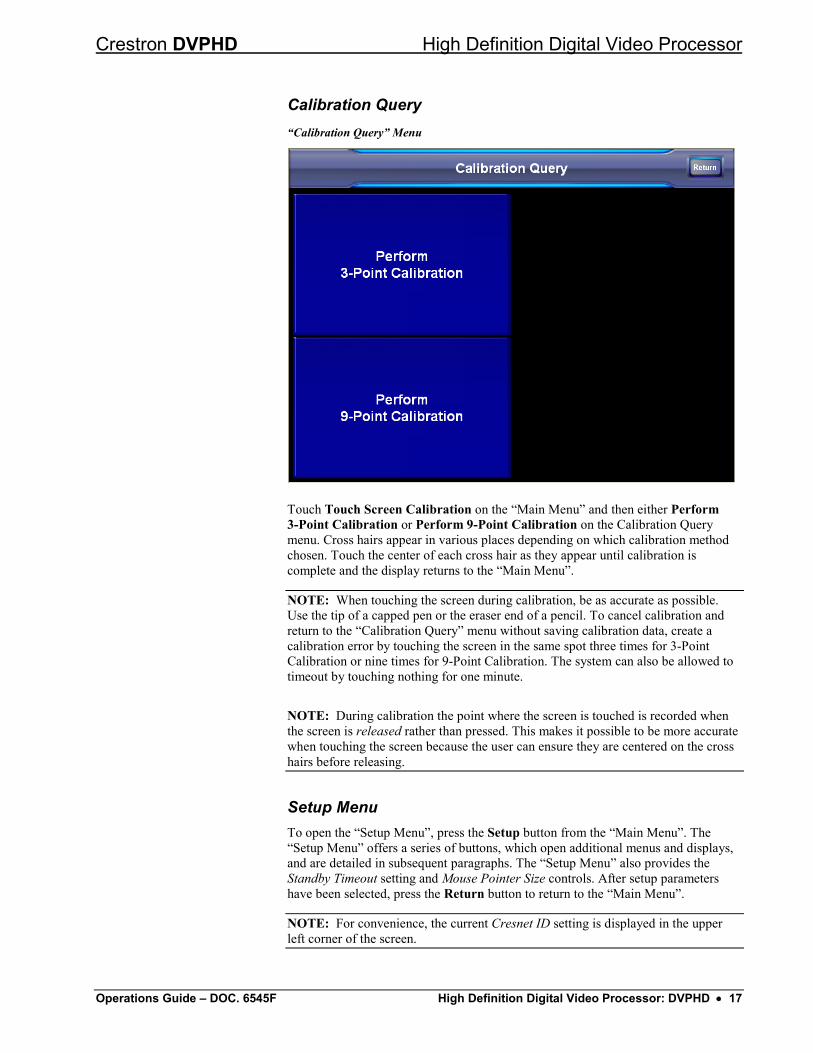
Calibration Query “Calibration Query” Menu
Touch Touch Screen Calibration on the “Main Menu” and then either Perform 3-Point Calibration or Perform 9-Point Calibration on the Calibration Query menu. Cross hairs appear in various places depending on which calibration method chosen. Touch the center of each cross hair as they appear until calibration is complete and the display returns to the “Main Menu”.
NOTE: When touching the screen during calibration, be as accurate as possible. Use the tip of a capped pen or the eraser end of a pencil. To cancel calibration and return to the “Calibration Query” menu without saving calibration data, create a calibration error by touching the screen in the same spot three times for 3-Point Calibration or nine times for 9-Point Calibration. The system can also be allowed to timeout by touching nothing for one minute.
NOTE: During calibration the point where the screen is touched is recorded when the screen is released rather than pressed. This makes it possible to be more accurate when touching the screen because the user can ensure they are centered on the cross hairs before releasing.
Setup Menu To open the “Setup Menu”, press the Setup button from the “Main Menu”. The “Setup Menu” offers a series of buttons, which open additional menus and displays, and are detailed in subsequent paragraphs. The “Setup Menu” also provides the Standby Timeout setting and Mouse Pointer Size controls. After setup parameters have been selected, press the Return button to return to the “Main Menu”.
NOTE: For convenience, the current Cresnet ID setting is displayed in the upper left corner of the screen.

High Definition Digital Video Processor Crestron DVPHD
18 • High Definition Digital Video Processor: DVPHD Operations Guide – DOC. 6545F
NOTE: All DVPHD Video Processor settings are automatically saved in non-volatile memory.
“Setup Menu”
Interface Menu The DVPHD communicates with a control system to activate commands or to display feedback from components within the system. The communication interface must be correctly configured or communication does not occur. To set communication parameters, touch Interface on the “Setup Menu” to display the “Interface Menu”.
The Cresnet network identity number (Cresnet ID also known as the Net ID) is displayed on the “Interface Menu”. Cresnet ID is the two-digit hexadecimal number. The hexadecimal number can range from 03 to FE and must correspond to the Net ID set in the SIMPL Windows program of the Cresnet system. Matching IDs between the DVPHD and the SIMPL Windows program is required if data is to be successfully transferred. Net ID for the DVPHD is factory set to 03. No two devices in the same system can have the same Net ID.
Crestron DVPHD High Definition Digital Video Processor
Operations Guide – DOC. 6545F High Definition Digital Video Processor: DVPHD • 19
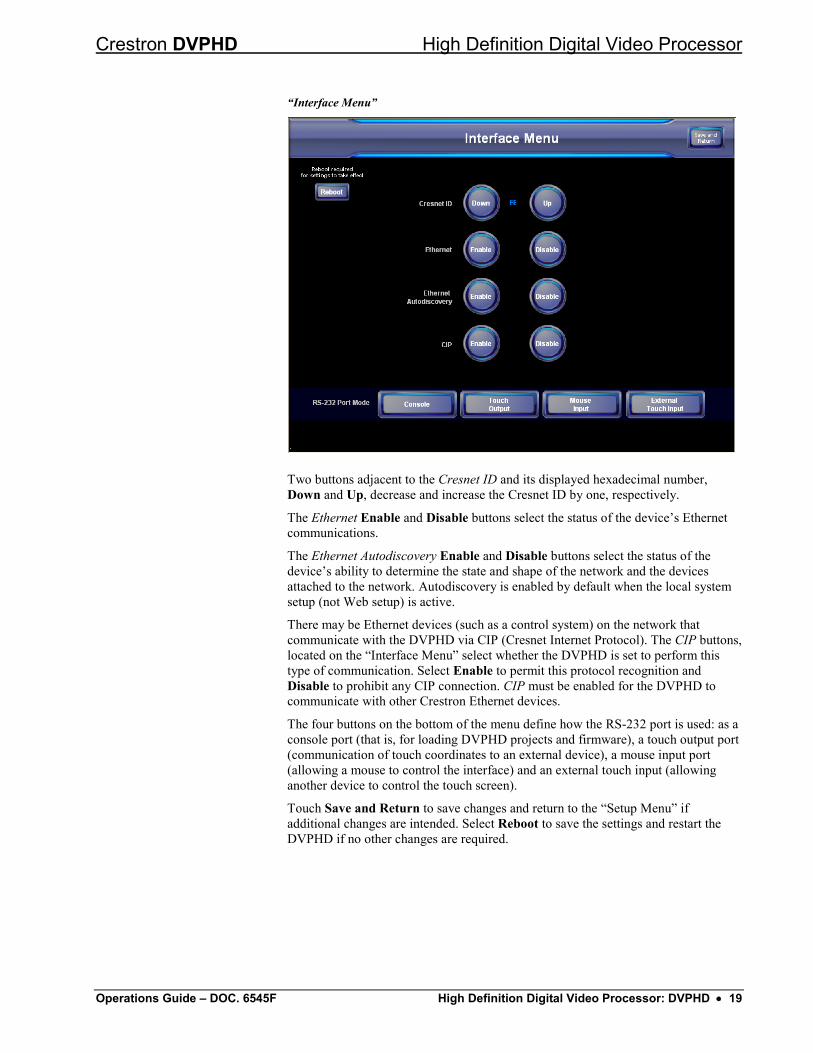
“Interface Menu”
Two buttons adjacent to the Cresnet ID and its displayed hexadecimal number, Down and Up, decrease and increase the Cresnet ID by one, respectively.
The Ethernet Enable and Disable buttons select the status of the device’s Ethernet communications.
The Ethernet Autodiscovery Enable and Disable buttons select the status of the device’s ability to determine the state and shape of the network and the devices attached to the network. Autodiscovery is enabled by default when the local system setup (not Web setup) is active.
There may be Ethernet devices (such as a control system) on the network that communicate with the DVPHD via CIP (Cresnet Internet Protocol). The CIP buttons, located on the “Interface Menu” select whether the DVPHD is set to perform this type of communication. Select Enable to permit this protocol recognition and Disable to prohibit any CIP connection. CIP must be enabled for the DVPHD to communicate with other Crestron Ethernet devices.
The four buttons on the bottom of the menu define how the RS-232 port is used: as a console port (that is, for loading DVPHD projects and firmware), a touch output port (communication of touch coordinates to an external device), a mouse input port (allowing a mouse to control the interface) and an external touch input (allowing another device to control the touch screen).
Touch Save and Return to save changes and return to the “Setup Menu” if additional changes are intended. Select Reboot to save the settings and restart the DVPHD if no other changes are required.
High Definition Digital Video Processor Crestron DVPHD
20 • High Definition Digital Video Processor: DVPHD Operations Guide – DOC. 6545F
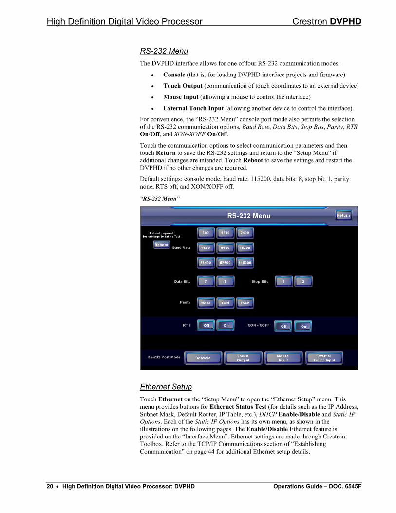
RS-232 Menu The DVPHD interface allows for one of four RS-232 communication modes:
• Console (that is, for loading DVPHD interface projects and firmware)
• Touch Output (communication of touch coordinates to an external device)
• Mouse Input (allowing a mouse to control the interface)
• External Touch Input (allowing another device to control the interface).
For convenience, the “RS-232 Menu” console port mode also permits the selection of the RS-232 communication options, Baud Rate, Data Bits, Stop Bits, Parity, RTS On/Off, and XON-XOFF On/Off.
Touch the communication options to select communication parameters and then touch Return to save the RS-232 settings and return to the “Setup Menu” if additional changes are intended. Touch Reboot to save the settings and restart the DVPHD if no other changes are required.
Default settings: console mode, baud rate: 115200, data bits: 8, stop bit: 1, parity: none, RTS off, and XON/XOFF off.
“RS-232 Menu”
Ethernet Setup Touch Ethernet on the “Setup Menu” to open the “Ethernet Setup” menu. This menu provides buttons for Ethernet Status Test (for details such as the IP Address, Subnet Mask, Default Router, IP Table, etc.), DHCP Enable/Disable and Static IP Options. Each of the Static IP Options has its own menu, as shown in the illustrations on the following pages. The Enable/Disable Ethernet feature is provided on the “Interface Menu”. Ethernet settings are made through Crestron Toolbox. Refer to the TCP/IP Communications section of “Establishing Communication” on page 44 for additional Ethernet setup details.

Crestron DVPHD High Definition Digital Video Processor
Operations Guide – DOC. 6545F High Definition Digital Video Processor: DVPHD • 21
NOTE: The IP addresses shown in the following examples are only representative and do not reflect real or suggested addresses.
“Ethernet Setup” Menu (Static)
“Ethernet Static IP Settings” Menu
High Definition Digital Video Processor Crestron DVPHD
22 • High Definition Digital Video Processor: DVPHD Operations Guide – DOC. 6545F
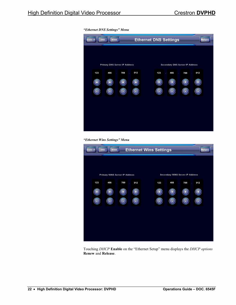
“Ethernet DNS Settings” Menu
“Ethernet Wins Settings” Menu
Touching DHCP Enable on the “Ethernet Setup” menu displays the DHCP options Renew and Release.

Crestron DVPHD High Definition Digital Video Processor
Operations Guide – DOC. 6545F High Definition Digital Video Processor: DVPHD • 23
“Ethernet Setup” Menu (DHCP Enabled)
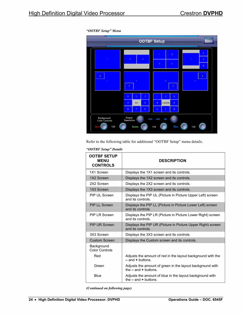
OOTBF Setup The DVPHD can be configured to display up to nine pre-set and 255 custom layout combinations of video outputs consisting of a wide variety of screens and nested screens along with background color and output resolution controls. Each configuration, accessed by clicking on the sample graphics, is individually customizable for Source, Transition Effect, Transition Duration, Z-Order (if applicable), Position and Size (if applicable), Preview Window Aspect Ratio, Output Resolution, Window Color, Text Color, and Text Justify. Maintain Aspect Ratio and Active buttons are provided as are Apply and Cancel to confirm or reject any changes.
High Definition Digital Video Processor Crestron DVPHD
24 • High Definition Digital Video Processor: DVPHD Operations Guide – DOC. 6545F
“OOTBF Setup” Menu
Refer to the following table for additional “OOTBF Setup” menu details.
“OOTBF Setup” Details
OOTBF SETUP MENU
CONTROLS DESCRIPTION
1X1 Screen Displays the 1X1 screen and its controls. 1X2 Screen Displays the 1X2 screen and its controls. 2X2 Screen Displays the 2X2 screen and its controls. 1X3 Screen Displays the 1X3 screen and its controls. PIP UL Screen Displays the PIP UL (Picture in Picture Upper Left) screen
and its controls. PIP LL Screen Displays the PIP LL (Picture in Picture Lower Left) screen
and its controls. PIP LR Screen Displays the PIP LR (Picture in Picture Lower Right) screen
and its controls. PIP UR Screen Displays the PIP UR (Picture in Picture Upper Right) screen
and its controls. 3X3 Screen Displays the 3X3 screen and its controls. Custom Screen Displays the Custom screen and its controls. Background Color Controls
Red Adjusts the amount of red in the layout background with the – and + buttons.
Green Adjusts the amount of green in the layout background with the – and + buttons.
Blue Adjusts the amount of blue in the layout background with the – and + buttons.
(Continued on following page)
Crestron DVPHD High Definition Digital Video Processor
Operations Guide – DOC. 6545F High Definition Digital Video Processor: DVPHD • 25
“OOTBF Setup” Details (Continued)
OOTBF SETUP MENU
CONTROLS DESCRIPTION
Output Resolution
Adjusts the output resolution in the range of 640 x 400 @ 85Hz minimum to 1920 x 1200 @60Hz maximum with the – and + buttons.
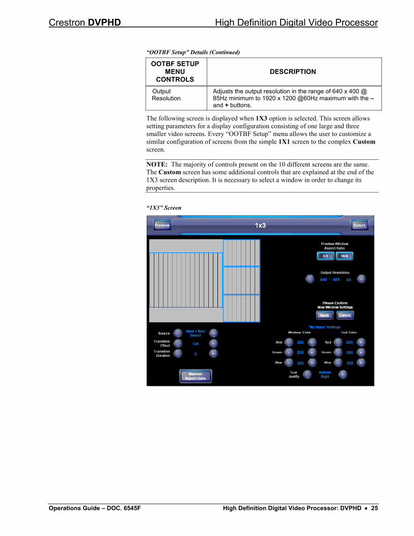
The following screen is displayed when 1X3 option is selected. This screen allows setting parameters for a display configuration consisting of one large and three smaller video screens. Every “OOTBF Setup” menu allows the user to customize a similar configuration of screens from the simple 1X1 screen to the complex Custom screen.
NOTE: The majority of controls present on the 10 different screens are the same. The Custom screen has some additional controls that are explained at the end of the 1X3 screen description. It is necessary to select a window in order to change its properties.
“1X3” Screen
High Definition Digital Video Processor Crestron DVPHD
26 • High Definition Digital Video Processor: DVPHD Operations Guide – DOC. 6545F
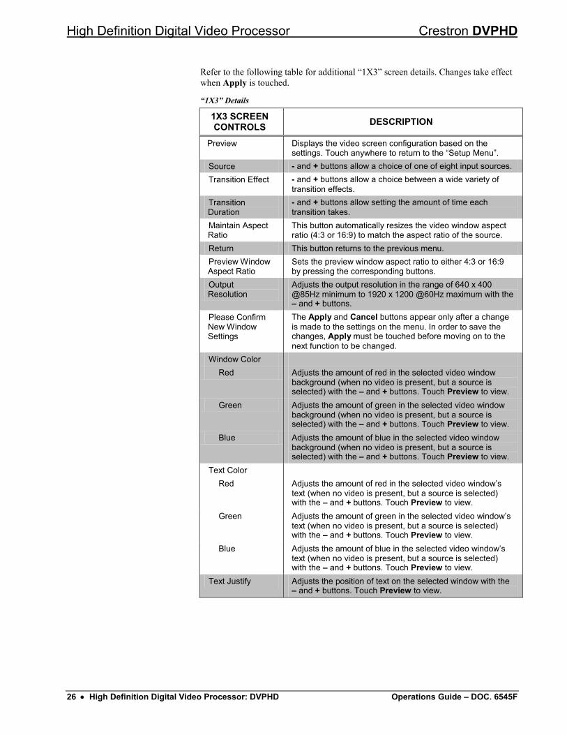
Refer to the following table for additional “1X3” screen details. Changes take effect when Apply is touched.
“1X3” Details
1X3 SCREEN CONTROLS DESCRIPTION
Preview Displays the video screen configuration based on the settings. Touch anywhere to return to the “Setup Menu”.
Source - and + buttons allow a choice of one of eight input sources. Transition Effect - and + buttons allow a choice between a wide variety of
transition effects. Transition Duration
- and + buttons allow setting the amount of time each transition takes.
Maintain Aspect Ratio
This button automatically resizes the video window aspect ratio (4:3 or 16:9) to match the aspect ratio of the source.
Return This button returns to the previous menu. Preview Window Aspect Ratio
Sets the preview window aspect ratio to either 4:3 or 16:9 by pressing the corresponding buttons.
Output Resolution
Adjusts the output resolution in the range of 640 x 400 @85Hz minimum to 1920 x 1200 @60Hz maximum with the – and + buttons.
Please Confirm New Window Settings
The Apply and Cancel buttons appear only after a change is made to the settings on the menu. In order to save the changes, Apply must be touched before moving on to the next function to be changed.
Window Color Red Adjusts the amount of red in the selected video window
background (when no video is present, but a source is selected) with the – and + buttons. Touch Preview to view.
Green Adjusts the amount of green in the selected video window background (when no video is present, but a source is selected) with the – and + buttons. Touch Preview to view.
Blue Adjusts the amount of blue in the selected video window background (when no video is present, but a source is selected) with the – and + buttons. Touch Preview to view.
Text Color Red Adjusts the amount of red in the selected video window’s
text (when no video is present, but a source is selected) with the – and + buttons. Touch Preview to view.
Green Adjusts the amount of green in the selected video window’s text (when no video is present, but a source is selected) with the – and + buttons. Touch Preview to view.
Blue Adjusts the amount of blue in the selected video window’s text (when no video is present, but a source is selected) with the – and + buttons. Touch Preview to view.
Text Justify Adjusts the position of text on the selected window with the – and + buttons. Touch Preview to view.

Crestron DVPHD High Definition Digital Video Processor
Operations Guide – DOC. 6545F High Definition Digital Video Processor: DVPHD • 27
Additional Controls – Custom Screen Only
CUSTOM SCREEN
CONTROLS DESCRIPTION
Presets Displays the “OOTBF Presets” screen and its controls. X Pos Adjusts the X coordinate position of the video window on
the selected screen with the – and + buttons. The number indicates the position of the upper left corner of the selected screen.
Y Pos Adjusts the Y coordinate position of the video window on the selected screen with the – and + buttons. The number indicates the position of the upper left corner of the selected screen.
X Size Adjusts the X dimension size of the video window on the selected screen with the – and + buttons.
Y Size Adjusts the Y dimension size of the video window on the selected screen with the – and + buttons.
Active Sets the selected window to the active state so it displays. Only active windows are displayed. Only takes effect after the Apply is touched.
The following screen is displayed when the Presets button is selected. This screen allows loading and saving presents to the Custom screen as well as loading from and saving to Compact Flash®.
“OOTBF Presets” Screen
High Definition Digital Video Processor Crestron DVPHD
28 • High Definition Digital Video Processor: DVPHD Operations Guide – DOC. 6545F
Additional Controls – Custom Screen Only – “OOTBF Presets” Screen
OOTBF PRESETS SCREEN
CONTROLS DESCRIPTION
Preset Name Displays the assigned name of the current preset. Preset Index The – and + buttons allow selecting the preset to be loaded
or the Preset Index number where the user can save a new custom configuration. Up 256 custom presets can be saved.
Load Preset to Custom Page
This button loads the preset selected by the Preset Index controls to the Custom page.
Save Custom Page to Preset
This button saves the current Custom page configuration to the Preset Index.
Return This button returns to the previous menu. Reload Presets from Compact Flash
This button loads presets stored in compact flash to the DVPHD for use in the Custom page.
Save All Presets to Compact Flash
This button saves all presets to compact flash.
Output Setup To open the “Output Setup” screen, touch Output on the “Setup Menu”. The “Output Setup” screen offers QuickMedia Transmit ID controls as well as EDID (Extended Display Identification Data) information on the DVI display attached to the DVPHD.
NOTE: EDID information is only displayed for EDID compliant display devices.

Crestron DVPHD High Definition Digital Video Processor
Operations Guide – DOC. 6545F High Definition Digital Video Processor: DVPHD • 29
“Output Setup” Screen
Refer to the following table for additional “Output Setup” screen details.
Output Setup Details
OUTPUT SETUP SCREEN
CONTROLS DESCRIPTION
QM Transmit ID Allows transmission of video processor’s QM ID. Manual transmits a specific QM ID, adjustable with the DN and UP buttons. Auto, the default setting, transmits the Cresnet ID as the QM ID.
Auto HDMI Mode Allows Auto HDMI Mode to be switched on or off using the Enable and Disable buttons. When enabled, the optimum resolution of the attached monitor is detected and the output is set to match. When disabled, the output is user-defined. It is enabled by default.
Video Setup The DVPHD can display up to eight fully-scalable and movable full motion video windows, each supporting DVI, HDMI, RGB, SDI, HD-SDI, component, S-video, and composite video signals from external AV and computer sources. These units also use auto-detect for DVI, HDMI, RGB, component, S-video, and composite video. They support NTSC/PAL interlaced video; HDTV up to 1080i/1080p; DVI/HDCP, HDMI/HDCP, and RGB up to WUXGA. Up to eight video inputs provide signals that can be routed to DVI, HDMI, or RGB, plus RGB via QM.
A table describing the video menu controls follows the illustrations. Touching Video on the “Setup Menu” opens the “Video Setup” menu shown on the following page. From here, the user can enter the setup screens for any of the eight video inputs by touching their respective buttons.

High Definition Digital Video Processor Crestron DVPHD
30 • High Definition Digital Video Processor: DVPHD Operations Guide – DOC. 6545F
“Video Setup” Menu
Refer to the following table for additional “Video Setup” menu details. Each video input control, or button, shown on the “Video Setup” menu reflects the type of video input detected by that window. The various button states are described in the following table.
“Video Setup” Details
VIDEO SETUP MENU
CONTROLS DESCRIPTION
Setup Video 1 Displays the “Video 1 Setup” screen. By default, the “Video 1 Setup” screen displays video controls for: Brightness, Contrast, Saturation, Hue, Detail Enhancement, Noise Reduction and Noise Threshold on the right side of the screen.
Setup Video 2 Displays the “Video 2 Setup” screen. By default, the “Video 2 Setup” screen displays video controls for: Brightness, Contrast, Red, Green, Blue, Detail Enhancement, Noise Reduction and Noise Threshold on the right side of the screen.
Setup Video 3 Displays the “Video 3 Setup” screen. By default, the “Video 3 Setup” screen displays video controls for: Brightness, Contrast, Saturation, Hue, Detail Enhancement, Noise Reduction, and Noise Threshold on the right side of the screen.
Setup Video 4 Displays the “Video 4 Setup” screen. By default, the “Video 4 Setup” screen displays video controls for: Brightness, Contrast, Red, Green, Blue, Detail Enhancement, Noise Reduction, and Noise Threshold on the right side of the screen.
(Continued on following page)
Crestron DVPHD High Definition Digital Video Processor
Operations Guide – DOC. 6545F High Definition Digital Video Processor: DVPHD • 31
“Video Setup” Details (Continued)
VIDEO SETUP MENU
CONTROLS DESCRIPTION
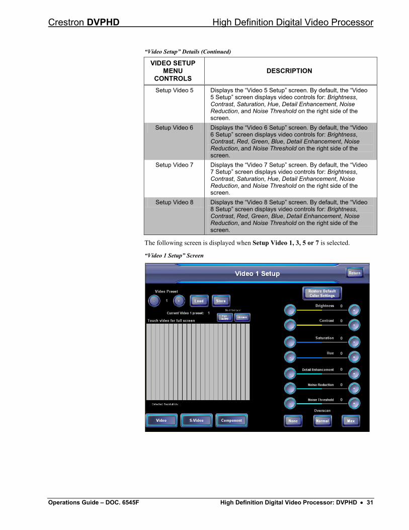
Setup Video 5 Displays the “Video 5 Setup” screen. By default, the “Video 5 Setup” screen displays video controls for: Brightness, Contrast, Saturation, Hue, Detail Enhancement, Noise Reduction, and Noise Threshold on the right side of the screen.
Setup Video 6 Displays the “Video 6 Setup” screen. By default, the “Video 6 Setup” screen displays video controls for: Brightness, Contrast, Red, Green, Blue, Detail Enhancement, Noise Reduction, and Noise Threshold on the right side of the screen.
Setup Video 7 Displays the “Video 7 Setup” screen. By default, the “Video 7 Setup” screen displays video controls for: Brightness, Contrast, Saturation, Hue, Detail Enhancement, Noise Reduction, and Noise Threshold on the right side of the screen.
Setup Video 8 Displays the “Video 8 Setup” screen. By default, the “Video 8 Setup” screen displays video controls for: Brightness, Contrast, Red, Green, Blue, Detail Enhancement, Noise Reduction, and Noise Threshold on the right side of the screen.
The following screen is displayed when Setup Video 1, 3, 5 or 7 is selected.
“Video 1 Setup” Screen

High Definition Digital Video Processor Crestron DVPHD
32 • High Definition Digital Video Processor: DVPHD Operations Guide – DOC. 6545F
“Video 1 Setup” Details – Video, S-Video and Component
VIDEO 1 SETUP SCREEN
CONTROLS DESCRIPTION
Video Preset Displays the current Video Preset number. Saved presets can also be called up using this control. The – and + buttons decrement and increment the displayed value.
Load Preset Loads the selected Video Preset. Store Preset Stores any changes made to the video setup at the
displayed preset number. De-interlacer1 Video de-interlacer can be switched between High Quality
and Standard for the selected input. Detected Signal Types
These buttons display the detected signal type. They are not otherwise active.
Video Highlighted when a video signal is detected. S-Video Highlighted when an S-video signal is detected. Component Highlighted when component video is detected.
Restore Default Color Settings
Restores the video settings to their original defaults.
Color Control When Video, S-Video or Component is selected as the video type, these controls are available. The Restore Default Color Settings button places the controls at their midpoint.
Brightness2 Adjusts video image brightness with the – and + buttons. Contrast2 Adjusts video image contrast with the – and + buttons. Saturation2 Adjusts video image saturation with the – and + buttons. Hue2 Adjusts video image hue with the – and + buttons. Detail Enhancement
Adjusts video image sharpness with the – and + buttons.
Noise Reduction
Adjusts the amount of video image noise reduction with the – and + buttons.
Noise Threshold
Adjusts the threshold of video image noise with the – and + buttons.
Overscan These controls adjust the amount of video information at the edges of the image. This part of the video picture is usually beyond the display capabilities of the screen.
None Sets the video screen so there is 1% overscan. The amount of used screen area is smallest in this configuration.
Normal Sets the video screen for 3% overscan (default). This results in more area of the screen being used.
Max This sets the video screen for 5% overscan. This results in some loss of information at the screen edges.
1. When one input on an input card is set to Standard the other input on the same card is set to High Quality and vice versa.
2. Video default is zero (0) for each of the video parameters (Brightness, Contrast, Saturation, and Hue).
Crestron DVPHD High Definition Digital Video Processor
Operations Guide – DOC. 6545F High Definition Digital Video Processor: DVPHD • 33
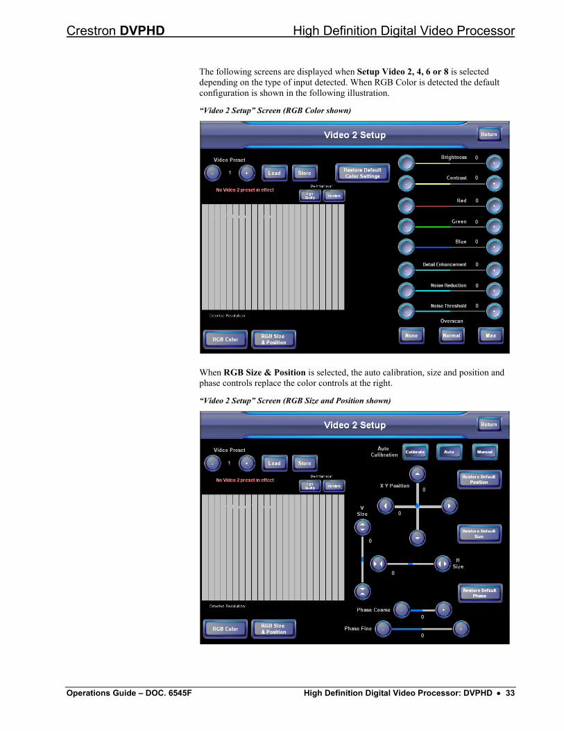
The following screens are displayed when Setup Video 2, 4, 6 or 8 is selected depending on the type of input detected. When RGB Color is detected the default configuration is shown in the following illustration.
“Video 2 Setup” Screen (RGB Color shown)
When RGB Size & Position is selected, the auto calibration, size and position and phase controls replace the color controls at the right.
“Video 2 Setup” Screen (RGB Size and Position shown)
High Definition Digital Video Processor Crestron DVPHD
34 • High Definition Digital Video Processor: DVPHD Operations Guide – DOC. 6545F
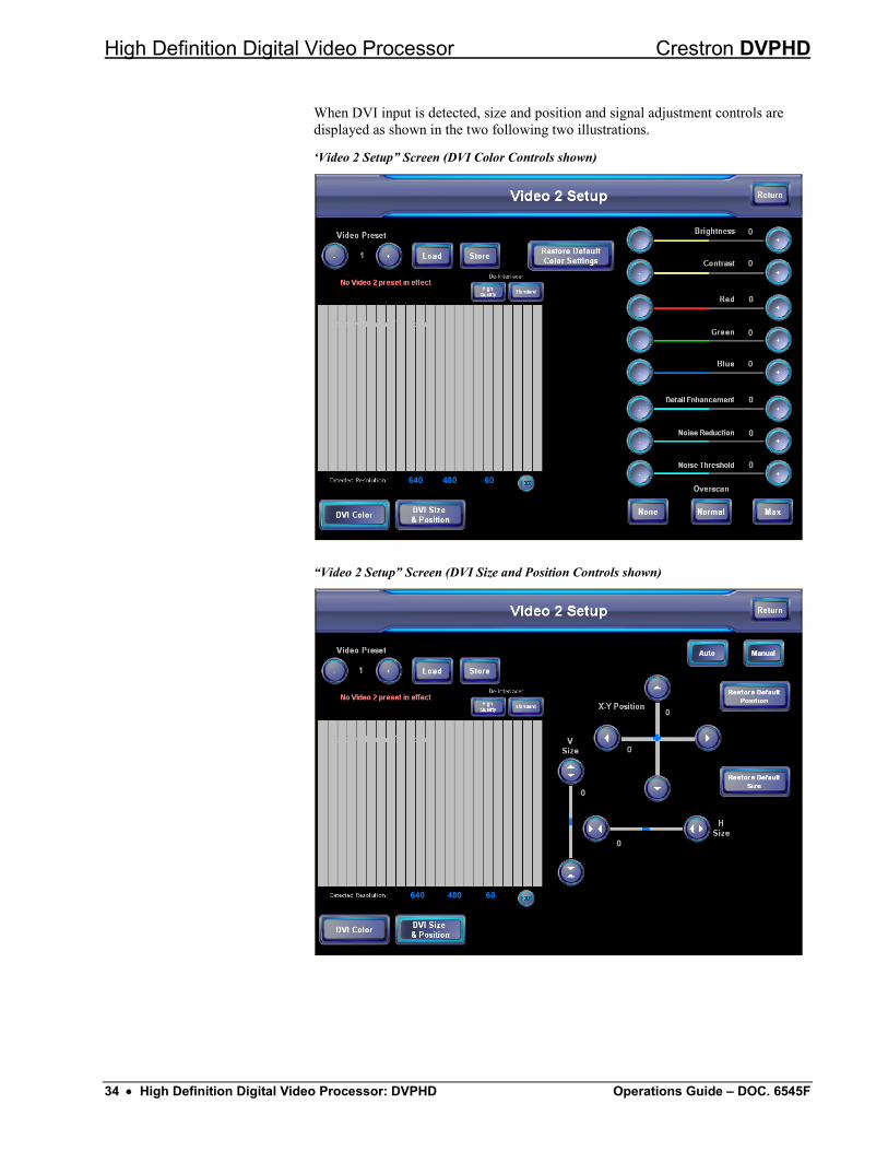
When DVI input is detected, size and position and signal adjustment controls are displayed as shown in the two following two illustrations.
‘Video 2 Setup” Screen (DVI Color Controls shown)
“Video 2 Setup” Screen (DVI Size and Position Controls shown)

Crestron DVPHD High Definition Digital Video Processor
Operations Guide – DOC. 6545F High Definition Digital Video Processor: DVPHD • 35
When SDI input is detected, only adjustment controls are displayed as shown in the following illustration.
“Video 2 Setup” Screen (SDI Controls shown)
“Video 2 Setup” Details – RGB Color and RGB Size and Position
VIDEO 2 SETUP SCREEN
CONTROLS DESCRIPTION
Video Preset Displays the current Video Preset number. Saved presets can also be called up using this control. The – and + buttons decrement and increment the displayed value.
Load Preset Loads the selected Video Preset. Store Preset Stores any changes made to the video setup at the
displayed preset number. Detected Resolution
Displays the video resolution detected by the DVPHD.
HDCP Indicates that HDCP is active. (DVI-HDMI connections only.)
Restore Default Color Settings
Restores the video settings to their original defaults.
(Continued on following page)

High Definition Digital Video Processor Crestron DVPHD
36 • High Definition Digital Video Processor: DVPHD Operations Guide – DOC. 6545F
“Video 2 Setup” Details – RGB Color and RGB Size and Position (Continued)
VIDEO 2 SETUP SCREEN
CONTROLS DESCRIPTION
Color Control When RGB Color is selected as the video type, these controls are available. The Restore Default Color Settings button places the controls at their midpoint.
Brightness1, 2 Adjusts video image brightness with the – and + buttons. Contrast1, 2 Adjusts video image contrast with the – and + buttons. Red1, 2 Adjusts the amount of red in the video signal with the –
and + buttons. Green1, 2 Adjusts the amount of green in the video signal with the –
and + buttons. Blue1, 2 Adjusts the amount of blue in the video signal with the –
and + buttons. Detail Enhancement
Adjusts video image sharpness with the – and + buttons.
Noise Reduction Adjusts the amount of video image noise reduction with the – and + buttons.
Noise Threshold Adjusts the threshold of video image noise with the – and + buttons.
Overscan These controls adjust the amount of video information at the edges of the image. This part of the video picture is usually beyond the display capabilities of the screen.
None Sets the video screen so there is 0% overscan. The amount of used screen area is smallest in this configuration. This must be set for PC sources.
Normal Sets the video screen for 3% overscan (default). This results in more area of the screen being used.
Max This sets the video screen for 5% overscan. This results in some loss of information at the screen edges.
(Continued on following page)
Crestron DVPHD High Definition Digital Video Processor
Operations Guide – DOC. 6545F High Definition Digital Video Processor: DVPHD • 37
“Video 2 Setup” Details – RGB Color and RGB Size and Position (Continued)
VIDEO 2 SETUP SCREEN
CONTROLS DESCRIPTION
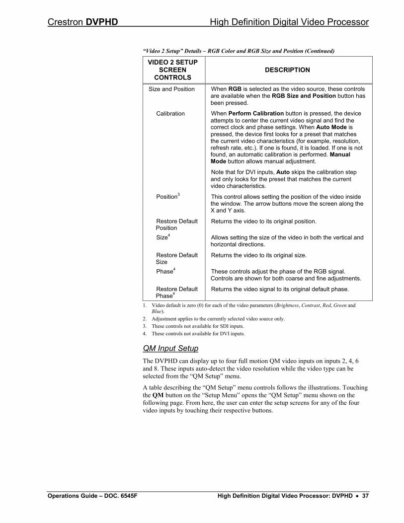
Size and Position When RGB is selected as the video source, these controls are available when the RGB Size and Position button has been pressed.
Calibration When Perform Calibration button is pressed, the device attempts to center the current video signal and find the correct clock and phase settings. When Auto Mode is pressed, the device first looks for a preset that matches the current video characteristics (for example, resolution, refresh rate, etc.). If one is found, it is loaded. If one is not found, an automatic calibration is performed. Manual Mode button allows manual adjustment.
Note that for DVI inputs, Auto skips the calibration step and only looks for the preset that matches the current video characteristics.
Position3 This control allows setting the position of the video inside the window. The arrow buttons move the screen along the X and Y axis.
Restore Default Position
Returns the video to its original position.
Size4 Allows setting the size of the video in both the vertical and horizontal directions.
Restore Default Size
Returns the video to its original size.
Phase4 These controls adjust the phase of the RGB signal. Controls are shown for both coarse and fine adjustments.
Restore Default Phase4
Returns the video signal to its original default phase.
1. Video default is zero (0) for each of the video parameters (Brightness, Contrast, Red, Green and Blue).
2. Adjustment applies to the currently selected video source only. 3. These controls not available for SDI inputs. 4. These controls not available for DVI inputs.
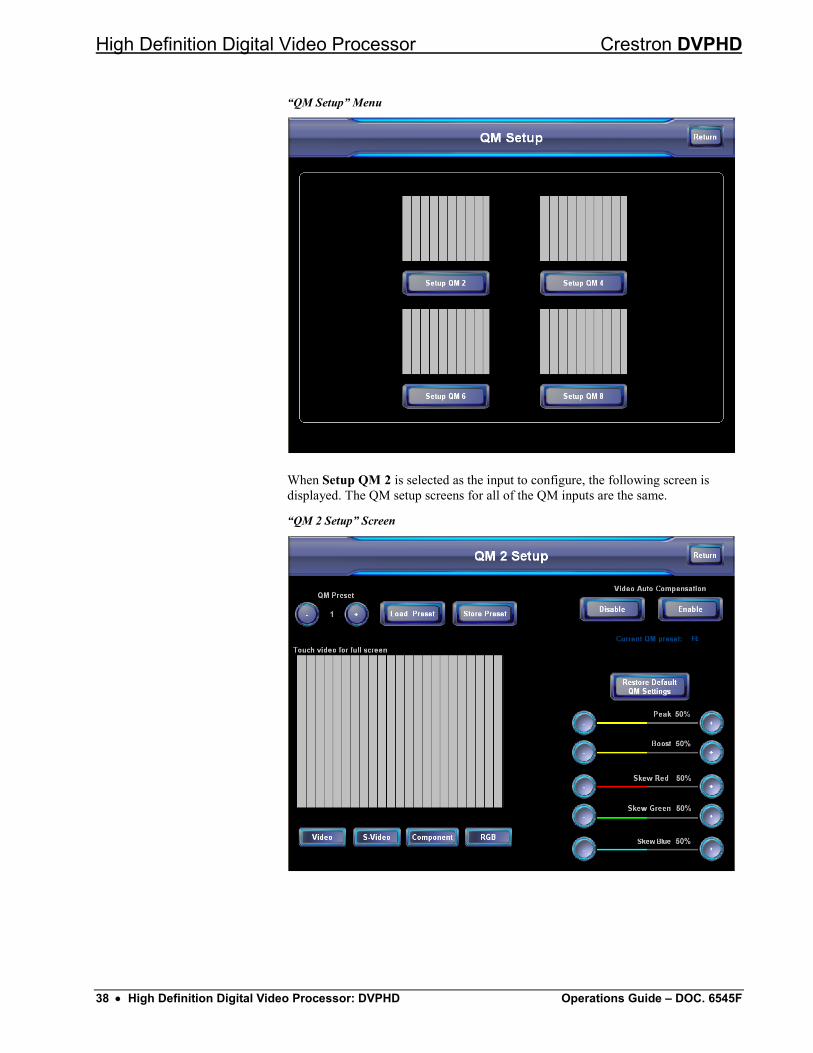
QM Input Setup The DVPHD can display up to four full motion QM video inputs on inputs 2, 4, 6 and 8. These inputs auto-detect the video resolution while the video type can be selected from the “QM Setup” menu.
A table describing the “QM Setup” menu controls follows the illustrations. Touching the QM button on the “Setup Menu” opens the “QM Setup” menu shown on the following page. From here, the user can enter the setup screens for any of the four video inputs by touching their respective buttons.
High Definition Digital Video Processor Crestron DVPHD
38 • High Definition Digital Video Processor: DVPHD Operations Guide – DOC. 6545F
“QM Setup” Menu
When Setup QM 2 is selected as the input to configure, the following screen is displayed. The QM setup screens for all of the QM inputs are the same.
“QM 2 Setup” Screen

Crestron DVPHD High Definition Digital Video Processor
Operations Guide – DOC. 6545F High Definition Digital Video Processor: DVPHD • 39
“QM 2 Setup” Details
QM 2 SETUP SCREEN
CONTROLS DESCRIPTION
QM Preset Displays the current QM Preset number. Saved presets can also be called up using this control. The – and + buttons decrement and increment the displayed value.
Load Preset Loads the selected QM Preset. Store Preset Stores any changes made to the QM setup at the
displayed preset number. Detected Signal Types
These buttons allow the signal type to be selected on a QM source.
Video Selects a video signal. S-Video Selects an S-video signal. Component Selects a component video signal. RGB Selects an RGB video signal.
Video Auto Compensation
These buttons disable or enable auto compensation on the selected QM input. When enabled the QM preset transmitted with the signal is automatically loaded.
Current QM Preset Displays the QM preset currently in force. Restore Default QM Settings
Pressing this button restores QM settings to their original default values.
Peak Peak adjusts for high-frequency attenuation that can occur over long cable lengths.
Boost Boost compensates for overall signal loss that can occur over long cable lengths.
Skew Red Adjusts the timing position of the red signal on the skew test pattern to compensate for any losses caused by long cable runs.
Skew Green Adjusts the timing position of the green signal on the skew test pattern to compensate for any losses caused by long cable runs.
Skew Blue Adjusts the timing position of the blue signal on the skew test pattern to compensate for any losses caused by long cable runs.
Diagnostics To obtain the “Diagnostics Menu”, touch Diagnostics on the “Main Menu”. The “Diagnostics Menu” offers a series of buttons for various diagnostic tools. These tools should only be used under the supervision of a Crestron customer service representative during telephone support. A detailed discussion of the options available from the ‘Diagnostics Menu” is beyond the scope of this manual.

High Definition Digital Video Processor Crestron DVPHD
40 • High Definition Digital Video Processor: DVPHD Operations Guide – DOC. 6545F
Installation Ventilation The DVPHD should be used in a well-ventilated area. The venting holes should not
be obstructed under any circumstances
To prevent overheating, do not operate this product in an area that exceeds the environmental temperature range listed in the table of specifications. Consider using forced air ventilation and/or incrementing the spacing between units to reduce overheating. Contact with thermal insulating materials should be avoided on all sides of the unit.
Rack Mounting The DVPHD can be mounted in a rack or stacked with other equipment. Two “ears” are provided with the DVPHD so that the unit can be rack mounted. These ears must be installed prior to mounting. Complete the following procedure to attach the ears to the unit. The only tool required is a #1 or #2 Phillips screwdriver.
WARNING: To prevent bodily injury when mounting or servicing this unit in a rack, observe the following guidelines:
• When mounting this unit in a partially filled rack, load the rack from the bottom to the top with the heaviest component at the bottom of the rack.
• If the rack is provided with stabilizing devices, install the stabilizers before mounting or servicing the unit in the rack.
NOTE: Observe the following guidelines when installing equipment in a rack:
• Elevated Operating Ambient Temperature - If installed in a closed or multi-unit rack assembly, the operating ambient temperature of the rack environment may be greater than room ambient temperature. Therefore, consideration should be given to installing the equipment in an environment compatible with the maximum ambient temperature (Tma) specified by the manufacturer.
• Reduced Air Flow - Installation of the equipment in a rack should be such that the amount of airflow required for safe operation of the equipment is not compromised.
• Mechanical Loading - Mounting of the equipment in the rack should be such that a hazardous condition is not achieved due to uneven mechanical loading.
• Circuit Overloading - Consideration should be given to the connection of the equipment to the supply circuit and the effect that overloading of the circuits might have on overcurrent protection and supply wiring. Appropriate consideration of equipment nameplate ratings should be used when addressing this concern.
• Reliable Earthing - Reliable earthing of rack-mounted equipment should be maintained. Particular attention should be given to supply connections other than direct connections to the branch circuit (e.g., use of power strips)
NOTE: If rack mounting is not required, rubber feet are provided for tabletop mounting or stacking. Apply the feet near the corner edges on the underside of the unit.
Crestron DVPHD High Definition Digital Video Processor
Operations Guide – DOC. 6545F High Definition Digital Video Processor: DVPHD • 41
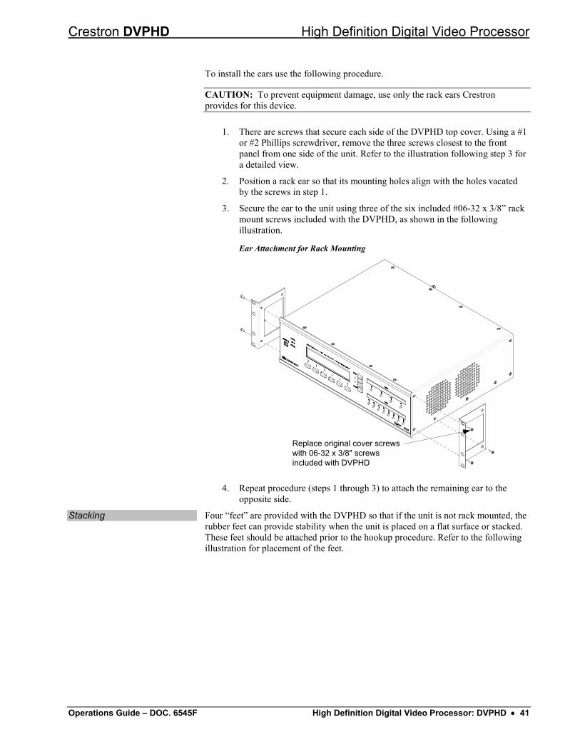
To install the ears use the following procedure.
CAUTION: To prevent equipment damage, use only the rack ears Crestron provides for this device.
1. There are screws that secure each side of the DVPHD top cover. Using a #1 or #2 Phillips screwdriver, remove the three screws closest to the front panel from one side of the unit. Refer to the illustration following step 3 for a detailed view.
2. Position a rack ear so that its mounting holes align with the holes vacated by the screws in step 1.
3. Secure the ear to the unit using three of the six included #06-32 x 3/8” rack mount screws included with the DVPHD, as shown in the following illustration.
Ear Attachment for Rack Mounting
Replace original cover screws with 06-32 x 3/8" screws included with DVPHD
4. Repeat procedure (steps 1 through 3) to attach the remaining ear to the opposite side.
Stacking Four “feet” are provided with the DVPHD so that if the unit is not rack mounted, the rubber feet can provide stability when the unit is placed on a flat surface or stacked. These feet should be attached prior to the hookup procedure. Refer to the following illustration for placement of the feet.

High Definition Digital Video Processor Crestron DVPHD
42 • High Definition Digital Video Processor: DVPHD Operations Guide – DOC. 6545F
Foot Placement for the DVPHD
Place feet in corners
NOTE: No more than two DVPHD units should be stacked.
Hardware Hookup Connect the Device Make the necessary connections as called out in the illustration that follows this
paragraph. Refer to “Network Wiring” on page 15 before attaching the 4-position terminal block connector. Apply power after all connections have been made.
When making connections to the DVPHD, note the following:
• Use Crestron power supplies for Crestron equipment.
• The included cable cannot be extended.
Hardware Connections for the DVPHD (Front View)
COMPUTER:Console Interface
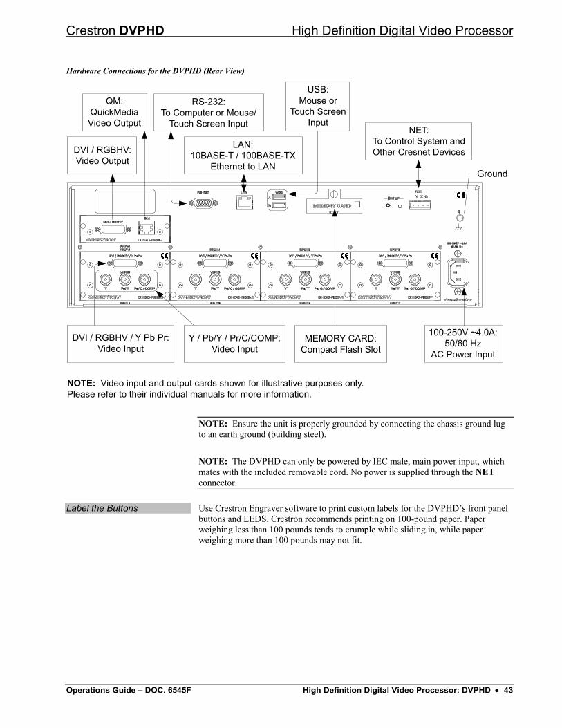
Crestron DVPHD High Definition Digital Video Processor
Operations Guide – DOC. 6545F High Definition Digital Video Processor: DVPHD • 43
Hardware Connections for the DVPHD (Rear View)
RS-232:To Computer or Mouse/
Touch Screen Input
QM:QuickMediaVideo Output
LAN:10BASE-T / 100BASE-TX
Ethernet to LAN
USB:Mouse or
Touch ScreenInput
NET:To Control System andOther Cresnet DevicesDVI / RGBHV:
Video Output
DVI / RGBHV / Y Pb Pr:Video Input
Ground
MEMORY CARD:Compact Flash Slot
Y / Pb/Y / Pr/C/COMP:Video Input
NOTE: Video input and output cards shown for illustrative purposes only.Please refer to their individual manuals for more information.
100-250V ~4.0A:50/60 Hz
AC Power Input
NOTE: Ensure the unit is properly grounded by connecting the chassis ground lug to an earth ground (building steel).
NOTE: The DVPHD can only be powered by IEC male, main power input, which mates with the included removable cord. No power is supplied through the NET connector.
Label the Buttons Use Crestron Engraver software to print custom labels for the DVPHD’s front panel buttons and LEDS. Crestron recommends printing on 100-pound paper. Paper weighing less than 100 pounds tends to crumple while sliding in, while paper weighing more than 100 pounds may not fit.
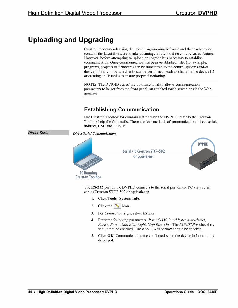
High Definition Digital Video Processor Crestron DVPHD
44 • High Definition Digital Video Processor: DVPHD Operations Guide – DOC. 6545F
Uploading and Upgrading Crestron recommends using the latest programming software and that each device contains the latest firmware to take advantage of the most recently released features. However, before attempting to upload or upgrade it is necessary to establish communication. Once communication has been established, files (for example, programs, projects or firmware) can be transferred to the control system (and/or device). Finally, program checks can be performed (such as changing the device ID or creating an IP table) to ensure proper functioning.
NOTE: The DVPHD out-of-the-box functionality allows communication parameters to be set from the front panel, an attached touch screen or via the Web interface.
Establishing Communication Use Crestron Toolbox for communicating with the DVPHD; refer to the Crestron Toolbox help file for details. There are four methods of communication: direct serial, indirect, USB and TCP/IP.
Direct Serial Direct Serial Communication
DVPHD
PC RunningCrestron Toolbox
Serial via Crestron STCP-502or Equivalent
The RS-232 port on the DVPHD connects to the serial port on the PC via a serial cable (Crestron STCP-502 or equivalent):
1. Click Tools | System Info.
2. Click the icon.
3. For Connection Type, select RS-232.
4. Enter the following parameters: Port: COM, Baud Rate: Auto-detect, Parity: None, Data Bits: Eight, Stop Bits: One. The XON/XOFF checkbox should not be checked. The RTS/CTS checkbox should be checked.
5. Click OK. Communications are confirmed when the device information is displayed.
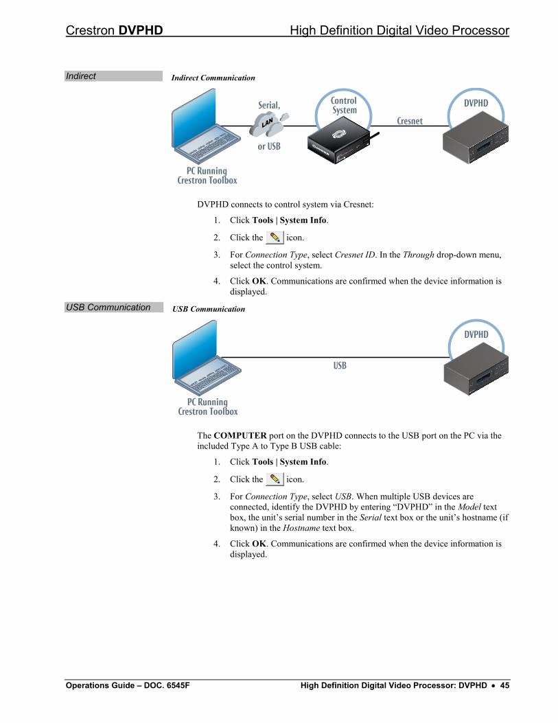
Crestron DVPHD High Definition Digital Video Processor
Operations Guide – DOC. 6545F High Definition Digital Video Processor: DVPHD • 45
Indirect Indirect Communication
PC RunningCrestron Toolbox
Serial,
or USB
LAN Cresnet
Control System
C O M PU TER
PWRN ETH W-RSW-RA C Q U IR E
A C TIVITY
DVPHD
DVPHD connects to control system via Cresnet:
1. Click Tools | System Info.
2. Click the icon.
3. For Connection Type, select Cresnet ID. In the Through drop-down menu, select the control system.
4. Click OK. Communications are confirmed when the device information is displayed.
USB Communication USB Communication
PC RunningCrestron Toolbox
USB
DVPHD
The COMPUTER port on the DVPHD connects to the USB port on the PC via the included Type A to Type B USB cable:
1. Click Tools | System Info.
2. Click the icon.
3. For Connection Type, select USB. When multiple USB devices are connected, identify the DVPHD by entering “DVPHD” in the Model text box, the unit’s serial number in the Serial text box or the unit’s hostname (if known) in the Hostname text box.
4. Click OK. Communications are confirmed when the device information is displayed.
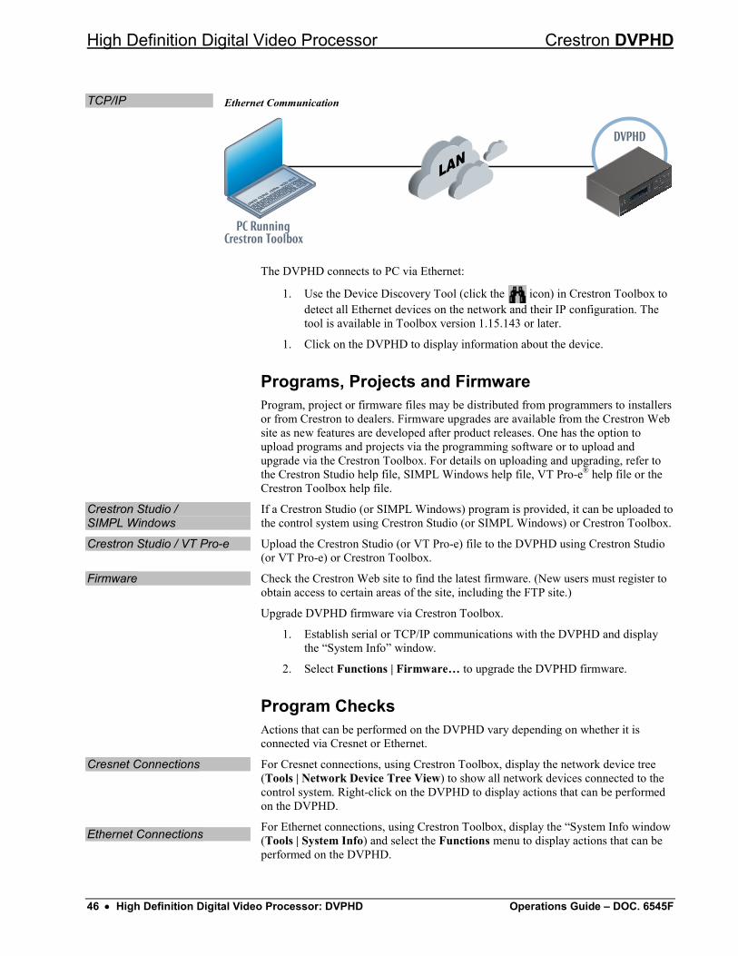
High Definition Digital Video Processor Crestron DVPHD
46 • High Definition Digital Video Processor: DVPHD Operations Guide – DOC. 6545F
TCP/IP Ethernet Communication
PC RunningCrestron Toolbox
LANDVPHD
The DVPHD connects to PC via Ethernet:
1. Use the Device Discovery Tool (click the icon) in Crestron Toolbox to detect all Ethernet devices on the network and their IP configuration. The tool is available in Toolbox version 1.15.143 or later.
1. Click on the DVPHD to display information about the device.
Programs, Projects and Firmware Program, project or firmware files may be distributed from programmers to installers or from Crestron to dealers. Firmware upgrades are available from the Crestron Web site as new features are developed after product releases. One has the option to upload programs and projects via the programming software or to upload and upgrade via the Crestron Toolbox. For details on uploading and upgrading, refer to the Crestron Studio help file, SIMPL Windows help file, VT Pro-e® help file or the Crestron Toolbox help file.
Crestron Studio / SIMPL Windows
If a Crestron Studio (or SIMPL Windows) program is provided, it can be uploaded to the control system using Crestron Studio (or SIMPL Windows) or Crestron Toolbox.
Crestron Studio / VT Pro-e Upload the Crestron Studio (or VT Pro-e) file to the DVPHD using Crestron Studio (or VT Pro-e) or Crestron Toolbox.
Firmware Check the Crestron Web site to find the latest firmware. (New users must register to obtain access to certain areas of the site, including the FTP site.)
Upgrade DVPHD firmware via Crestron Toolbox.
1. Establish serial or TCP/IP communications with the DVPHD and display the “System Info” window.
2. Select Functions | Firmware… to upgrade the DVPHD firmware.
Program Checks Actions that can be performed on the DVPHD vary depending on whether it is connected via Cresnet or Ethernet.
Cresnet Connections For Cresnet connections, using Crestron Toolbox, display the network device tree (Tools | Network Device Tree View) to show all network devices connected to the control system. Right-click on the DVPHD to display actions that can be performed on the DVPHD.
Ethernet Connections For Ethernet connections, using Crestron Toolbox, display the “System Info window (Tools | System Info) and select the Functions menu to display actions that can be performed on the DVPHD.

Crestron DVPHD High Definition Digital Video Processor
Operations Guide – DOC. 6545F High Definition Digital Video Processor: DVPHD • 47
Be sure to use the Crestron Toolbox to create the DVPHD IP table.
1. Select Functions | IP Table Setup.
2. Add, modify or delete entries in the IP table. The DVPHD can have only one IP table entry.
3. A defined IP table can be saved to a file or sent to the device.
Edit the control system’s IP table to include an entry for the DVPHD. The entry should list the DVPHD’s IP ID (specified on the DVPHD’s IP table) and the internal gateway IP address 127.0.0.1.

High Definition Digital Video Processor Crestron DVPHD
48 • High Definition Digital Video Processor: DVPHD Operations Guide – DOC. 6545F
Operation The out-of-the-box functionality built into it the DVPHD allows it to be operated from the front panel by means of the buttons and LCD display. The following sections describe the available functionality and menu structure.
The overall front panel menu structure of the DVPHD is illustrated by the following figure. Subsequent paragraphs describe the individual pages and their functions.
Front Panel Menu Structure
SETUP
VIDEO INPUTSQM SETUP
DISPLAY OUTPUTETHERNETCONTROL
QUICK OOTBF CONFIGENTER/EXIT SETUP PAGE
VIDEO INPUTS
SIGNAL INFORMATIONPICTURE ADJUSTMENTSHOW ALL VIDEO INFO
DISPLAY OUTPUT
OUTPUT RESOLUTIONAUTO HDMI
TEST SIGNALSSHOW/HIDE MOUSE
ETHERNET
STATUSDHCP
IP ADDRESSSUBNET MASK
DEFAULT ROUTERWINS
HOSTNAMEDOMAIN NAMEDNS SERVERS
CONTROL
MESSAGESRS232MODEPASSWORDS
TIME/DATEINFORMATIONCRESNET ID
OOTBFAUTODISCOVERY
ANNOTATIONREBOOT
SIGNAL INFO
TYPERESOLUTIONFREQUENCY
PICTURE ADJUSTMENT
Video PresetBrightnessContrast
SaturationHue
Over scanRed
GreenBlue
Detail EnhancementNoise ReductionNoise Threshold
V SizeH Size
X PositionY Position
Phase CoursePhase FineCalibrate
AutoManual
AUTO HDMI
TEST SIGNALS
Color barsWhite vertical lines
Gray scaleGrid patternBox Pattern
SMPTE BarsEBU Bars
StreakStreak Boost
Streak Boost SkewFreq. Adjust
Remove test pattern
PASSWORDS
FRONT PANEL
Error Log Messages
Error log-user clearable
INFORMATION
HARDWAREOPS VERSION
RS232MODE
CONSOLETOUCHOUTPUT
MOUSEEXT_TOUCH
SHOW/HIDE MOUSE
TIME/DATE
DateTime
CRESNET ID OOTBF
ENABLE OOTBFSELECT FORMAT
SOURCE SLECTION FOR CURRENT FORMATSOURCE SELECTION FOR ALL FORMAT
OOTBF OUTPUT RESOLUTIONOOTBF COLOR ADJUST
OOTBF SELECT START UP PAGECUSTOM PAD AREA SETTINGS
QUICK OOTBF CONFIG
OOTBF StatusCurrent page
Current windowCurrent window source
OUTPUT RESOLUTION
CURRENTSETUP
PROJECTOOTBF
AUTODISCOVERY
ANNOTATION
ENABLE ANNOTATIONCLEAR ANNOTATIONLIVE/FROZEN VIDEO
SET BRUSHSET COLOR
REMOTE OVERRIDE
SHOW ALL VIDEO INFO
Video Input Board 1 . . .Current HDCPHDCP StatusAll Receivers
All Transmitters
REBOOT
ENTER/EXIT SETUP PAGE
QM SETUP
SIGNAL TYPEQM PRESET
VIDEO AUTO COMPENSATIONPEAK
BOOSTSKEW RED
SKEW GREENSKEW BLUE
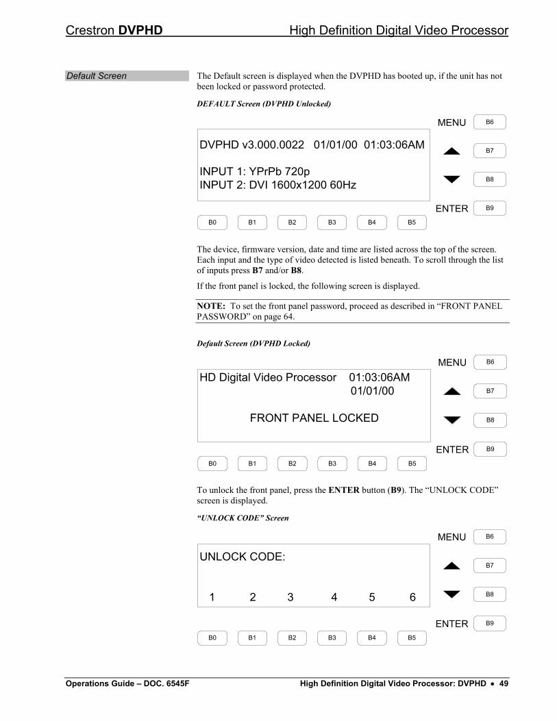
Crestron DVPHD High Definition Digital Video Processor
Operations Guide – DOC. 6545F High Definition Digital Video Processor: DVPHD • 49
Default Screen The Default screen is displayed when the DVPHD has booted up, if the unit has not been locked or password protected.
DEFAULT Screen (DVPHD Unlocked)
DVPHD v3.000.0022 01/01/00 01:03:06AM
INPUT 1: YPrPb 720pINPUT 2: DVI 1600x1200 60Hz
B6
B7
B8
B9
MENU
ENTERB0 B1 B2 B3 B4 B5
The device, firmware version, date and time are listed across the top of the screen. Each input and the type of video detected is listed beneath. To scroll through the list of inputs press B7 and/or B8.
If the front panel is locked, the following screen is displayed.
NOTE: To set the front panel password, proceed as described in “FRONT PANEL PASSWORD” on page 64.
Default Screen (DVPHD Locked)
HD Digital Video Processor 01:03:06AM 01/01/00
FRONT PANEL LOCKED
B6
B7
B8
B9
MENU
ENTERB0 B1 B2 B3 B4 B5
To unlock the front panel, press the ENTER button (B9). The “UNLOCK CODE” screen is displayed.
“UNLOCK CODE” Screen
UNLOCK CODE:
1 2 3 4 5 6
B6
B7
B8
B9
MENU
ENTERB0 B1 B2 B3 B4 B5

High Definition Digital Video Processor Crestron DVPHD
50 • High Definition Digital Video Processor: DVPHD Operations Guide – DOC. 6545F
To unlock the front panel, enter the four-number numeric password with the B0 through B5 keys and then press ENTER.
NOTE: Refer to “FRONT PANEL PASSWORD” on page 64 for instruction on setting up the password.
“SETUP” Menu The “SETUP” menu is accessed by pressing B9 (ENTER) while the Default screen (unlocked) is displayed.
“SETUP” Menu
SETUP >VIDEO INPUTS DISPLAY OUTPUT ETHERNET
B6
B7
B8
B9
MENU
ENTERB0 B1 B2 B3 B4 B5
The SETUP menu provides access to five other menus: “VIDEO INPUTS”, “DISPLAY OUTPUT”, “ETHERNET”, “CONTROL”, “QUICK OOTBF CONFIG”. Press B7 or B8 to scroll through the selections. Press B9 (ENTER) to reach the selected menu.
VIDEO INPUTS The VIDEO INPUTS menu shows the current input on the first line. Other active inputs can be selected by pressing the appropriate input button to the right of the display.
“VIDEO INPUTS” Menu
VIDEO INPUTS 1 >S IGNAL INFORMATION P ICTURE ADJUSTMENT SHOW ALL V IDEO INFO
B 6
B 7
B 8
B 9
MENU
ENTERB 0 B 1 B 2 B 3 B 4 B 5
This menu provides access to the “SIGNAL INFORMATION” screen, the “PICTURE ADJUSTMENT” menu and the “SHOW ALL VIDEO INFO” menu. Press B7 or B8 to scroll through the selections. Press B9 (ENTER) to open the selection.
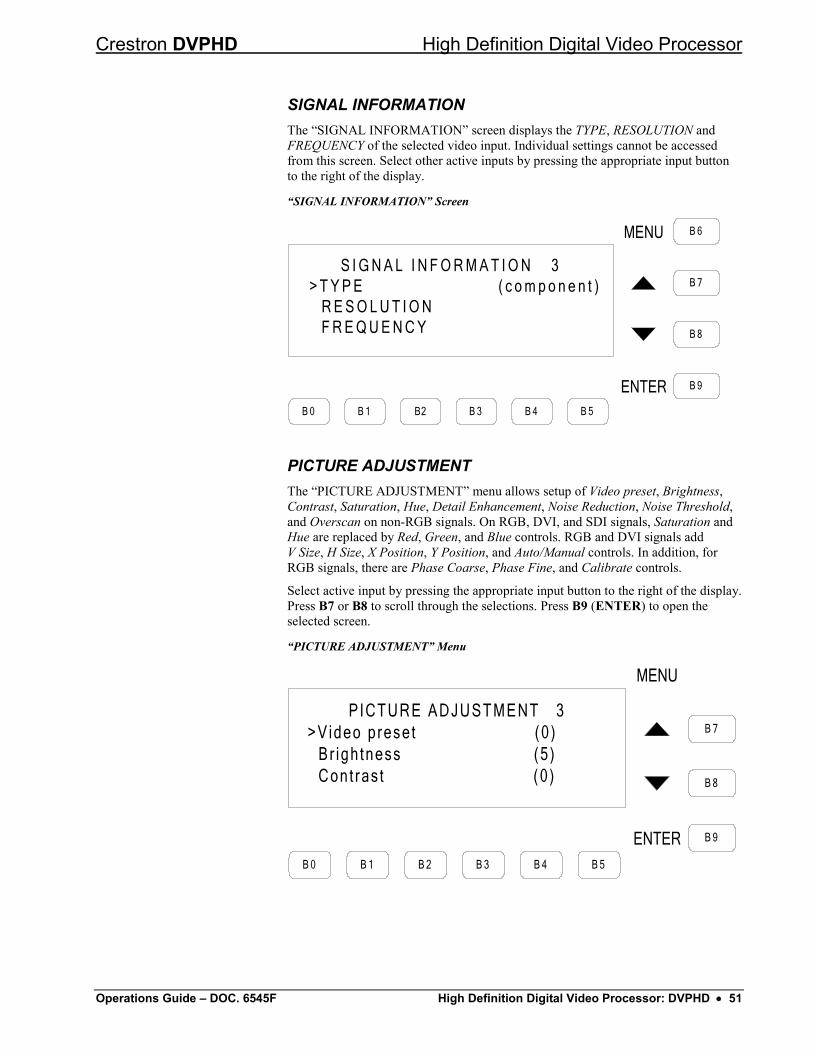
Crestron DVPHD High Definition Digital Video Processor
Operations Guide – DOC. 6545F High Definition Digital Video Processor: DVPHD • 51
SIGNAL INFORMATION The “SIGNAL INFORMATION” screen displays the TYPE, RESOLUTION and FREQUENCY of the selected video input. Individual settings cannot be accessed from this screen. Select other active inputs by pressing the appropriate input button to the right of the display.
“SIGNAL INFORMATION” Screen
S I G N A L I N F O R M A T I O N 3 > T Y P E ( c o m p o n e n t ) R E S O L U T I O N F R E Q U E N C Y
B 6
B 7
B 8
B 9
MENU
ENTERB 0 B 1 B2 B 3 B 4 B 5
PICTURE ADJUSTMENT The “PICTURE ADJUSTMENT” menu allows setup of Video preset, Brightness, Contrast, Saturation, Hue, Detail Enhancement, Noise Reduction, Noise Threshold, and Overscan on non-RGB signals. On RGB, DVI, and SDI signals, Saturation and Hue are replaced by Red, Green, and Blue controls. RGB and DVI signals add V Size, H Size, X Position, Y Position, and Auto/Manual controls. In addition, for RGB signals, there are Phase Coarse, Phase Fine, and Calibrate controls.
Select active input by pressing the appropriate input button to the right of the display. Press B7 or B8 to scroll through the selections. Press B9 (ENTER) to open the selected screen.
“PICTURE ADJUSTMENT” Menu
PICTURE ADJUSTMENT 3 > V ideo p rese t (0 ) B r igh tness (5 ) Con t ras t ( 0 )
B 7
B 8
B 9
MENU
ENTERB 0 B 1 B 2 B 3 B 4 B 5
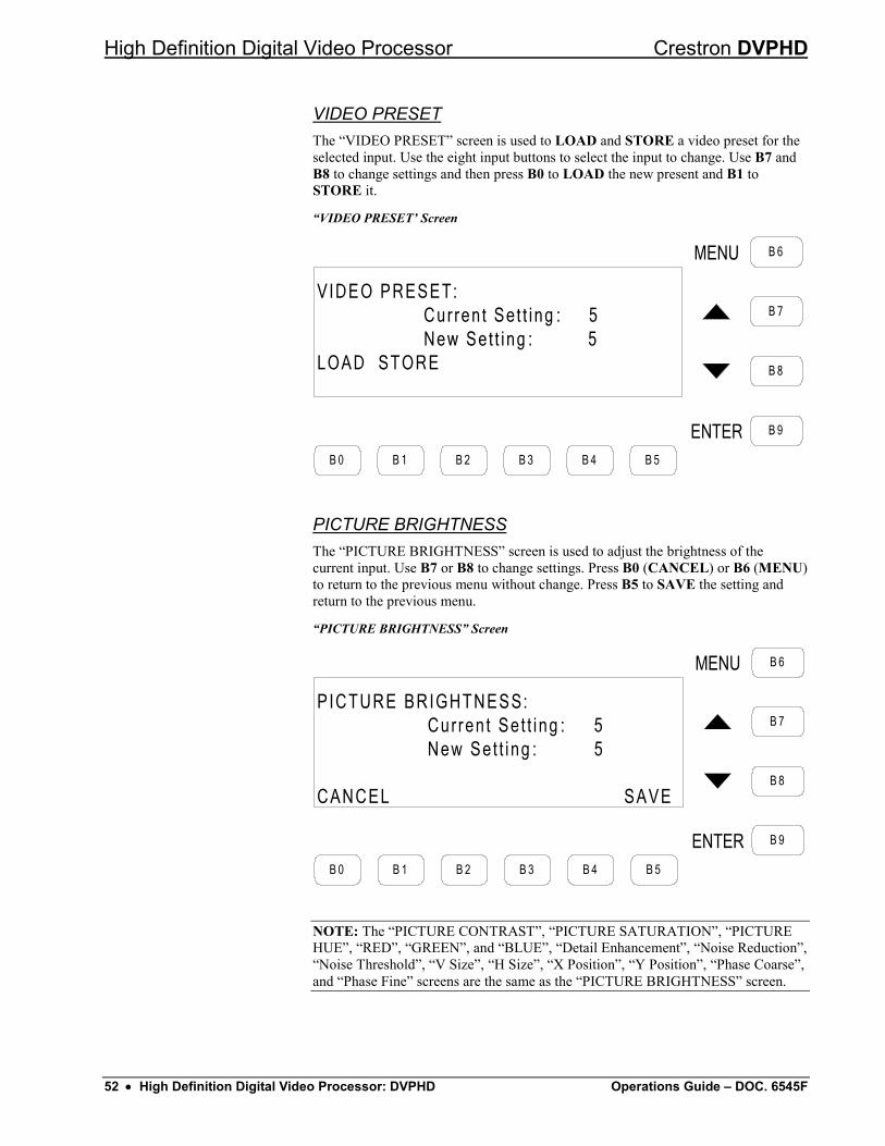
High Definition Digital Video Processor Crestron DVPHD
52 • High Definition Digital Video Processor: DVPHD Operations Guide – DOC. 6545F
VIDEO PRESET The “VIDEO PRESET” screen is used to LOAD and STORE a video preset for the selected input. Use the eight input buttons to select the input to change. Use B7 and B8 to change settings and then press B0 to LOAD the new present and B1 to STORE it.
“VIDEO PRESET’ Screen
VIDEO PRESET: Cur ren t Se t t ing : 5 New Set t ing : 5LOAD STORE
B 6
B 7
B 8
B 9
MENU
ENTERB 0 B 1 B 2 B 3 B 4 B 5
PICTURE BRIGHTNESS The “PICTURE BRIGHTNESS” screen is used to adjust the brightness of the current input. Use B7 or B8 to change settings. Press B0 (CANCEL) or B6 (MENU) to return to the previous menu without change. Press B5 to SAVE the setting and return to the previous menu.
“PICTURE BRIGHTNESS” Screen
PICTURE BRIGHTNESS: Cur ren t Se t t i ng : 5 New Set t i ng : 5 CANCEL SAVE
B 6
B 7
B 8
B 9
MENU
ENTERB 0 B 1 B 2 B 3 B 4 B 5
NOTE: The “PICTURE CONTRAST”, “PICTURE SATURATION”, “PICTURE HUE”, “RED”, “GREEN”, and “BLUE”, “Detail Enhancement”, “Noise Reduction”, “Noise Threshold”, “V Size”, “H Size”, “X Position”, “Y Position”, “Phase Coarse”, and “Phase Fine” screens are the same as the “PICTURE BRIGHTNESS” screen.

Crestron DVPHD High Definition Digital Video Processor
Operations Guide – DOC. 6545F High Definition Digital Video Processor: DVPHD • 53
Calibrate The “Calibrate?” screen is used to calibrate the current input. Press B5 (CONFIRM) to trigger calibration and return to the previous menu. Press B0 (CANCEL) or B6 (MENU) to return to the previous menu without calibration.
“Calibrate?” Screen
Cal ibrate?
CANCEL CONFIRM
B 6
B 7
B 8
B 9
MENU
ENTERB 0 B 1 B 2 B 3 B 4 B 5
AUTO/MANUAL The “AUTO/MANUAL” screen is used to set up Auto or Manual mode for the current input. Use B7 and B8 to toggle between modes. Press B5 (SAVE) to confirm the selection and return to the previous menu. Press B0 (CANCEL) or B6 (MENU) to return to the previous menu without change.
“AUTO/MANUAL” Screen
AUTO/MANUAL Current : (Manual ) New: (Manual)CANCEL SAVE
B 6
B 7
B 8
B 9
MENU
ENTERB 0 B 1 B 2 B 3 B 4 B 5
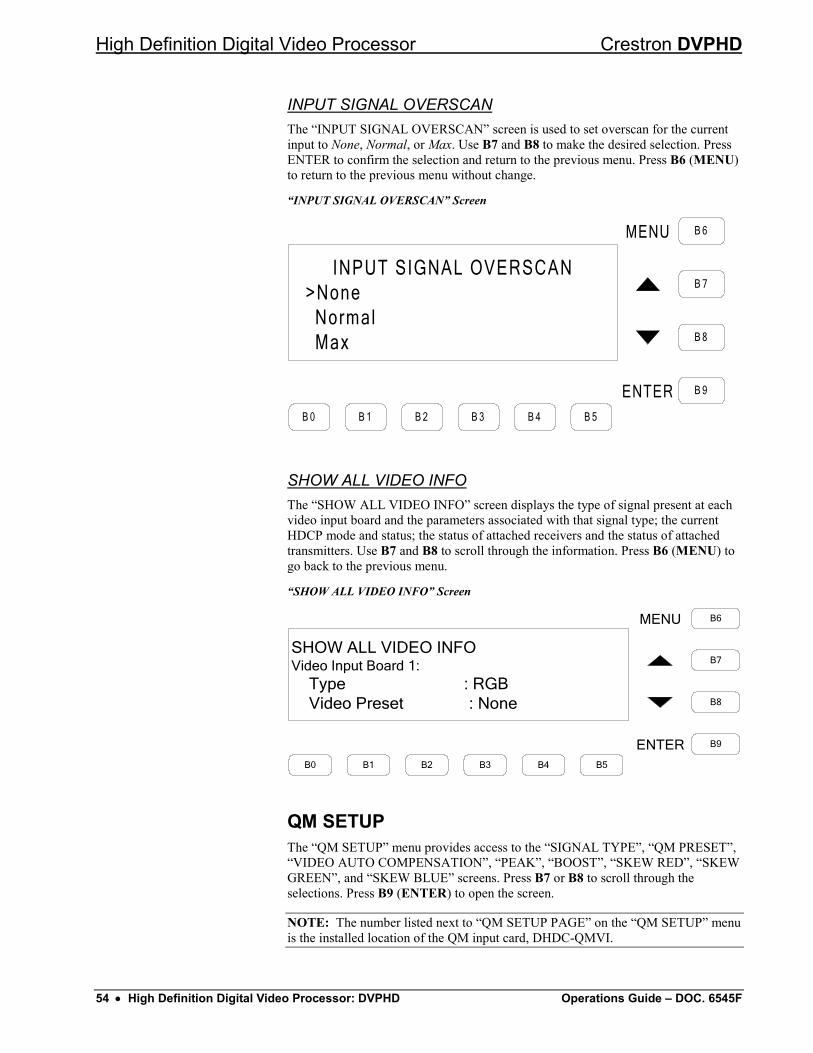
High Definition Digital Video Processor Crestron DVPHD
54 • High Definition Digital Video Processor: DVPHD Operations Guide – DOC. 6545F
INPUT SIGNAL OVERSCAN The “INPUT SIGNAL OVERSCAN” screen is used to set overscan for the current input to None, Normal, or Max. Use B7 and B8 to make the desired selection. Press ENTER to confirm the selection and return to the previous menu. Press B6 (MENU) to return to the previous menu without change.
“INPUT SIGNAL OVERSCAN” Screen
INPUT SIGNAL OVERSCAN >None Normal Max
B 6
B 7
B 8
B 9
MENU
ENTERB 0 B 1 B 2 B 3 B 4 B 5
SHOW ALL VIDEO INFO The “SHOW ALL VIDEO INFO” screen displays the type of signal present at each video input board and the parameters associated with that signal type; the current HDCP mode and status; the status of attached receivers and the status of attached transmitters. Use B7 and B8 to scroll through the information. Press B6 (MENU) to go back to the previous menu.
“SHOW ALL VIDEO INFO” Screen
SHOW ALL VIDEO INFOVideo Input Board 1: Type : RGB Video Preset : None
B6
B7
B8
B9
MENU
ENTERB0 B1 B2 B3 B4 B5
QM SETUP The “QM SETUP” menu provides access to the “SIGNAL TYPE”, “QM PRESET”, “VIDEO AUTO COMPENSATION”, “PEAK”, “BOOST”, “SKEW RED”, “SKEW GREEN”, and “SKEW BLUE” screens. Press B7 or B8 to scroll through the selections. Press B9 (ENTER) to open the screen.
NOTE: The number listed next to “QM SETUP PAGE” on the “QM SETUP” menu is the installed location of the QM input card, DHDC-QMVI.

Crestron DVPHD High Definition Digital Video Processor
Operations Guide – DOC. 6545F High Definition Digital Video Processor: DVPHD • 55
“QM SETUP” Menu
QM SETUP PAGE 2 > SIGNAL TYPE (RGB) QM PRESET (NONE) VIDEO AUTO COMPEN (ENABLED)
B6
B7
B8
B9
MENU
ENTERB0 B1 B2 B3 B4 B5
SIGNAL TYPE The “SIGNAL TYPE” screen is use to select signal type: Composite, S-Video, Component or RGB. Press B7 or B8 to scroll through the selections. Press B5 (SAVE) to save the setting and return to the previous menu. Press B0 (CANCEL) or B6 (MENU) to return to the previous menu without change.
“SIGNAL TYPE” Screen
SIGNAL TYPE Current Type : (Unknown) New Type: (RGB)CANCEL SAVE
B6
B7
B8
B9
MENU
ENTERB0 B1 B2 B3 B4 B5
QM PRESET The “QM PRESET” screen is used to LOAD and STORE the QM preset. Press input buttons 1 through 8 to select desired input. Press B7 or B8 to scroll through the selections. Press B0 (LOAD) to load the current present. Press B1 (STORE) to store the current settings to the preset.
“QM PRESET” Screen
VIDEO PRESET: Current Setting: 5 New Setting: 5LOAD STORE
B6
B7
B8
B9
MENU
ENTERB0 B1 B2 B3 B4 B5

High Definition Digital Video Processor Crestron DVPHD
56 • High Definition Digital Video Processor: DVPHD Operations Guide – DOC. 6545F
VIDEO AUTO COMPENSATION The “VIDEO AUTO COMPENSATION” screen is used to enable or disable the QM COMPENSATION. Press B7 or B8 to scroll through the selections. Press B5 (SAVE) to save the setting and return to the previous menu. Press B0 (CANCEL) or B6 (MENU) to return to the previous menu without change.
“VIDEO AUTO COMPENSATION” Screen
VIDEO AUTO COMPENSATION Current: (ENABLED) New: (DISABLED)CANCEL SAVE
B6
B7
B8
B9
MENU
ENTERB0 B1 B2 B3 B4 B5
PEAK The “PEAK” screen is used to change the peak value. Press B7 or B8 to scroll through the values. Press B5 (SAVE) to save the setting and return to the previous menu. Press B0 (CANCEL) or B6 (MENU) to return to the previous menu without change.
“PEAK” Screen
PEAK: Current: 0 New: 2CANCEL SAVE
B6
B7
B8
B9
MENU
ENTERB0 B1 B2 B3 B4 B5
NOTE: The “BOOST”, “SKEW RED”, “SKEW GREEN”, and “SKEW BLUE” screens operate in the same way as the “PEAK” screen.
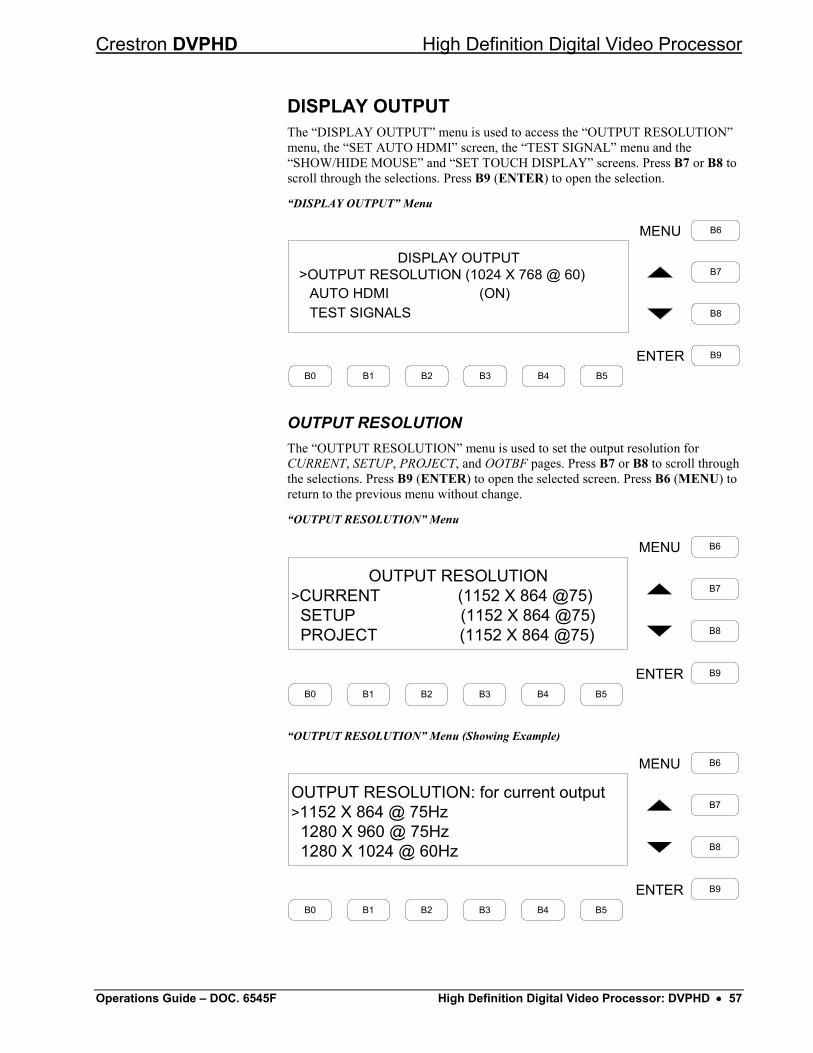
Crestron DVPHD High Definition Digital Video Processor
Operations Guide – DOC. 6545F High Definition Digital Video Processor: DVPHD • 57
DISPLAY OUTPUT The “DISPLAY OUTPUT” menu is used to access the “OUTPUT RESOLUTION” menu, the “SET AUTO HDMI” screen, the “TEST SIGNAL” menu and the “SHOW/HIDE MOUSE” and “SET TOUCH DISPLAY” screens. Press B7 or B8 to scroll through the selections. Press B9 (ENTER) to open the selection.
“DISPLAY OUTPUT” Menu
DISPLAY OUTPUT >OUTPUT RESOLUTION (1024 X 768 @ 60) AUTO HDMI (ON) TEST SIGNALS
B6
B7
B8
B9
MENU
ENTERB0 B1 B2 B3 B4 B5
OUTPUT RESOLUTION The “OUTPUT RESOLUTION” menu is used to set the output resolution for CURRENT, SETUP, PROJECT, and OOTBF pages. Press B7 or B8 to scroll through the selections. Press B9 (ENTER) to open the selected screen. Press B6 (MENU) to return to the previous menu without change.
“OUTPUT RESOLUTION” Menu
OUTPUT RESOLUTION>CURRENT (1152 X 864 @75) SETUP (1152 X 864 @75) PROJECT (1152 X 864 @75)
B6
B7
B8
B9
MENU
ENTERB0 B1 B2 B3 B4 B5
“OUTPUT RESOLUTION” Menu (Showing Example)
OUTPUT RESOLUTION: for current output>1152 X 864 @ 75Hz 1280 X 960 @ 75Hz 1280 X 1024 @ 60Hz
B6
B7
B8
B9
MENU
ENTERB0 B1 B2 B3 B4 B5
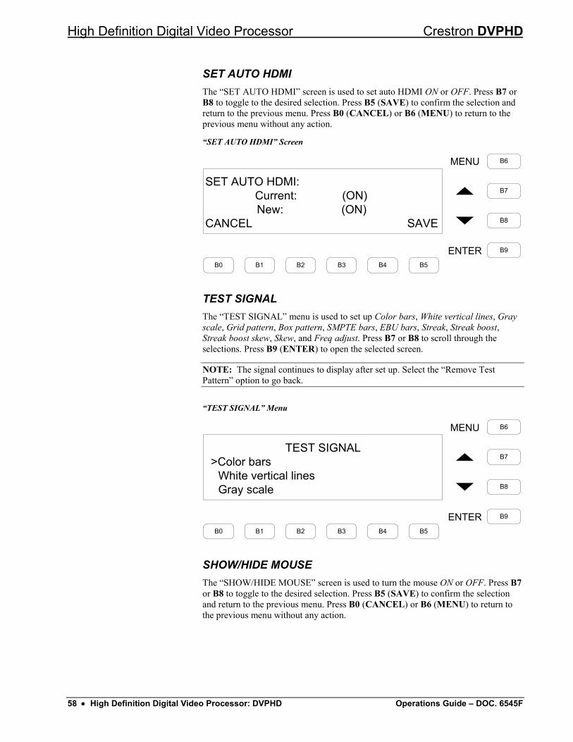
High Definition Digital Video Processor Crestron DVPHD
58 • High Definition Digital Video Processor: DVPHD Operations Guide – DOC. 6545F
SET AUTO HDMI The “SET AUTO HDMI” screen is used to set auto HDMI ON or OFF. Press B7 or B8 to toggle to the desired selection. Press B5 (SAVE) to confirm the selection and return to the previous menu. Press B0 (CANCEL) or B6 (MENU) to return to the previous menu without any action.
“SET AUTO HDMI” Screen
SET AUTO HDMI: Current: (ON) New: (ON)CANCEL SAVE
B6
B7
B8
B9
MENU
ENTERB0 B1 B2 B3 B4 B5
TEST SIGNAL The “TEST SIGNAL” menu is used to set up Color bars, White vertical lines, Gray scale, Grid pattern, Box pattern, SMPTE bars, EBU bars, Streak, Streak boost, Streak boost skew, Skew, and Freq adjust. Press B7 or B8 to scroll through the selections. Press B9 (ENTER) to open the selected screen.
NOTE: The signal continues to display after set up. Select the “Remove Test Pattern” option to go back.
“TEST SIGNAL” Menu
TEST SIGNAL >Color bars White vertical lines Gray scale
B6
B7
B8
B9
MENU
ENTERB0 B1 B2 B3 B4 B5
SHOW/HIDE MOUSE The “SHOW/HIDE MOUSE” screen is used to turn the mouse ON or OFF. Press B7 or B8 to toggle to the desired selection. Press B5 (SAVE) to confirm the selection and return to the previous menu. Press B0 (CANCEL) or B6 (MENU) to return to the previous menu without any action.
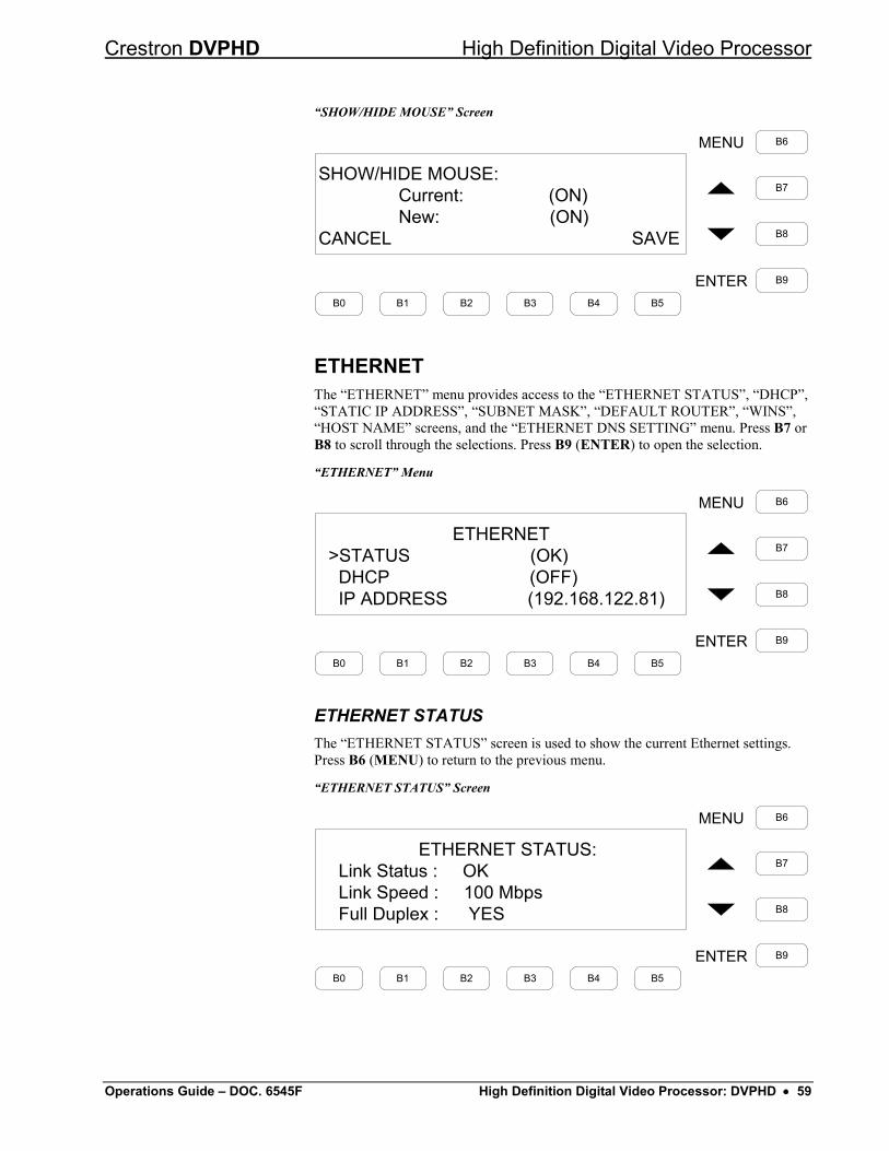
Crestron DVPHD High Definition Digital Video Processor
Operations Guide – DOC. 6545F High Definition Digital Video Processor: DVPHD • 59
“SHOW/HIDE MOUSE” Screen
SHOW/HIDE MOUSE: Current: (ON) New: (ON)CANCEL SAVE
B6
B7
B8
B9
MENU
ENTERB0 B1 B2 B3 B4 B5
ETHERNET The “ETHERNET” menu provides access to the “ETHERNET STATUS”, “DHCP”, “STATIC IP ADDRESS”, “SUBNET MASK”, “DEFAULT ROUTER”, “WINS”, “HOST NAME” screens, and the “ETHERNET DNS SETTING” menu. Press B7 or B8 to scroll through the selections. Press B9 (ENTER) to open the selection.
“ETHERNET” Menu
ETHERNET >STATUS (OK) DHCP (OFF) IP ADDRESS (192.168.122.81)
B6
B7
B8
B9
MENU
ENTERB0 B1 B2 B3 B4 B5
ETHERNET STATUS The “ETHERNET STATUS” screen is used to show the current Ethernet settings. Press B6 (MENU) to return to the previous menu.
“ETHERNET STATUS” Screen
ETHERNET STATUS: Link Status : OK Link Speed : 100 Mbps Full Duplex : YES
B6
B7
B8
B9
MENU
ENTERB0 B1 B2 B3 B4 B5
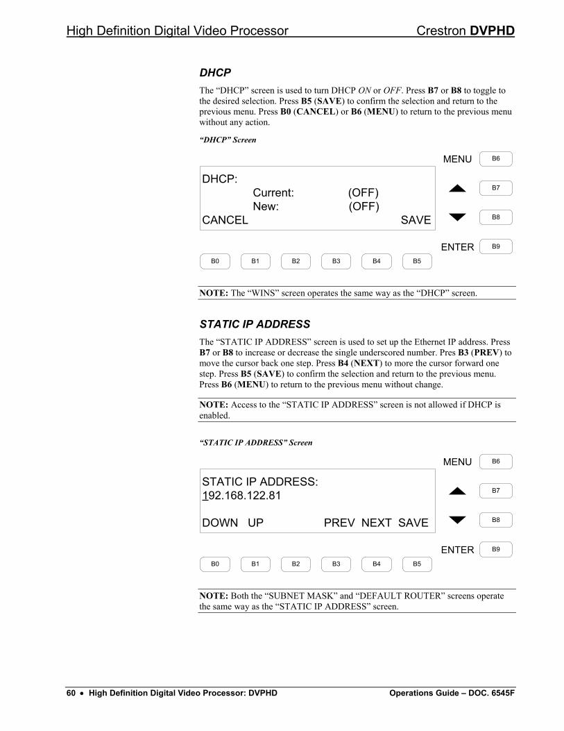
High Definition Digital Video Processor Crestron DVPHD
60 • High Definition Digital Video Processor: DVPHD Operations Guide – DOC. 6545F
DHCP The “DHCP” screen is used to turn DHCP ON or OFF. Press B7 or B8 to toggle to the desired selection. Press B5 (SAVE) to confirm the selection and return to the previous menu. Press B0 (CANCEL) or B6 (MENU) to return to the previous menu without any action.
“DHCP” Screen
DHCP: Current: (OFF) New: (OFF)CANCEL SAVE
B6
B7
B8
B9
MENU
ENTERB0 B1 B2 B3 B4 B5
NOTE: The “WINS” screen operates the same way as the “DHCP” screen.
STATIC IP ADDRESS The “STATIC IP ADDRESS” screen is used to set up the Ethernet IP address. Press B7 or B8 to increase or decrease the single underscored number. Pres B3 (PREV) to move the cursor back one step. Press B4 (NEXT) to more the cursor forward one step. Press B5 (SAVE) to confirm the selection and return to the previous menu. Press B6 (MENU) to return to the previous menu without change.
NOTE: Access to the “STATIC IP ADDRESS” screen is not allowed if DHCP is enabled.
“STATIC IP ADDRESS” Screen
STATIC IP ADDRESS:192.168.122.81 DOWN UP PREV NEXT SAVE
B6
B7
B8
B9
MENU
ENTERB0 B1 B2 B3 B4 B5
NOTE: Both the “SUBNET MASK” and “DEFAULT ROUTER” screens operate the same way as the “STATIC IP ADDRESS” screen.
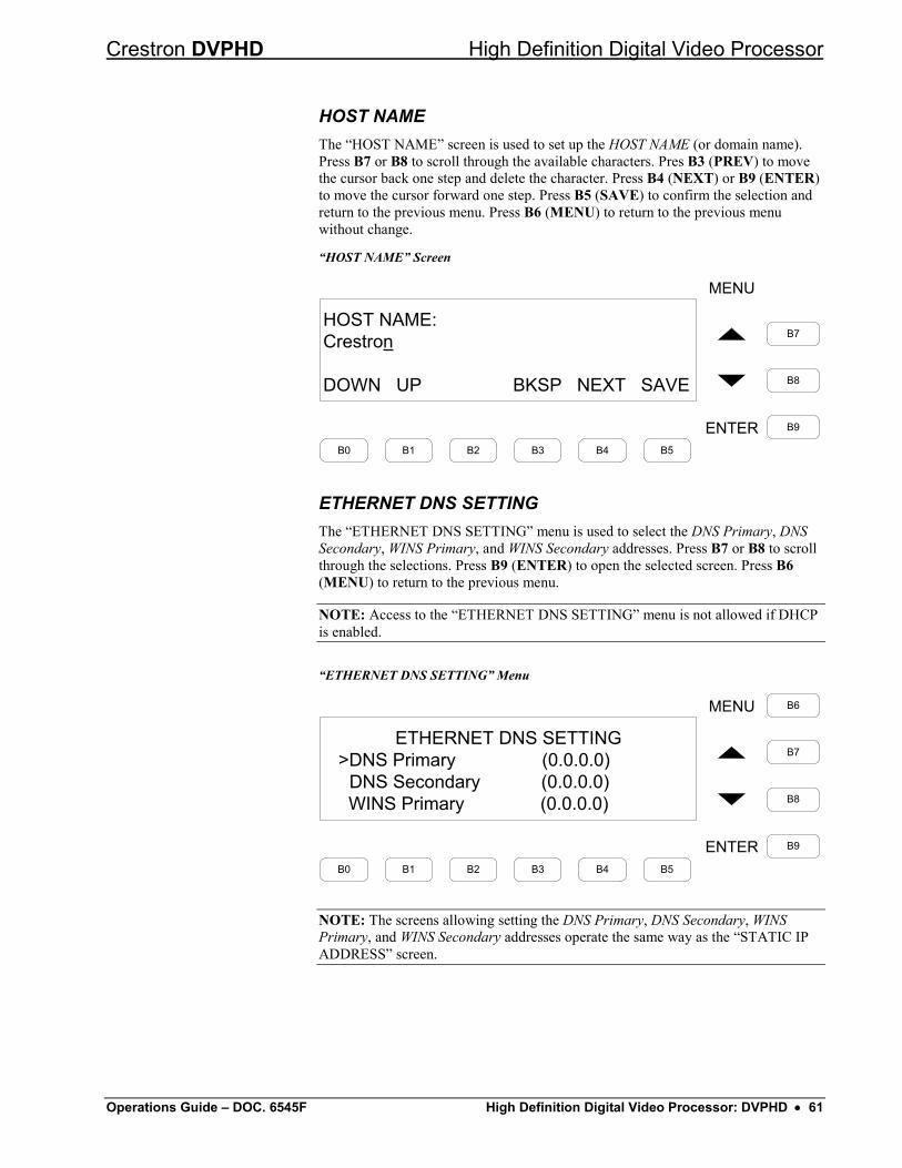
Crestron DVPHD High Definition Digital Video Processor
Operations Guide – DOC. 6545F High Definition Digital Video Processor: DVPHD • 61
HOST NAME The “HOST NAME” screen is used to set up the HOST NAME (or domain name). Press B7 or B8 to scroll through the available characters. Pres B3 (PREV) to move the cursor back one step and delete the character. Press B4 (NEXT) or B9 (ENTER) to move the cursor forward one step. Press B5 (SAVE) to confirm the selection and return to the previous menu. Press B6 (MENU) to return to the previous menu without change.
“HOST NAME” Screen
HOST NAME:Crestron
DOWN UP BKSP NEXT SAVE
B7
B8
B9
MENU
ENTERB0 B1 B2 B3 B4 B5
ETHERNET DNS SETTING The “ETHERNET DNS SETTING” menu is used to select the DNS Primary, DNS Secondary, WINS Primary, and WINS Secondary addresses. Press B7 or B8 to scroll through the selections. Press B9 (ENTER) to open the selected screen. Press B6 (MENU) to return to the previous menu.
NOTE: Access to the “ETHERNET DNS SETTING” menu is not allowed if DHCP is enabled.
“ETHERNET DNS SETTING” Menu
ETHERNET DNS SETTING >DNS Primary (0.0.0.0) DNS Secondary (0.0.0.0) WINS Primary (0.0.0.0)
B6
B7
B8
B9
MENU
ENTERB0 B1 B2 B3 B4 B5
NOTE: The screens allowing setting the DNS Primary, DNS Secondary, WINS Primary, and WINS Secondary addresses operate the same way as the “STATIC IP ADDRESS” screen.

High Definition Digital Video Processor Crestron DVPHD
62 • High Definition Digital Video Processor: DVPHD Operations Guide – DOC. 6545F
CONTROL The “CONTROL” menu provides access to the “Error Log Message”, “RS232 MODE” and “FRONT PANEL PASSWORD” screens, the “TIME/DATE” and “INFORMATION” menus, the “CRESNET ID” screen, the “Out Of The Box Functionality” menu, the “AUTODISCOVERY” screen, the “ANNOTATION” menu, and the “REBOOT” screen. Press B7 or B8 to scroll through the selections. Press B9 (ENTER) to open the selection.
“CONTROL” Menu
CONTROL >MESSAGES RS-232 MODE PASSWORD
B7
B8
B9
MENU
ENTERB0 B1 B2 B3 B4 B5
B6
Error Log Message The “Error Log Message” screen is used to display the system Error Log Message. Press B0 (FIRST) or B1 (LAST) to switch between the first line and the last line of the message. Press B2 (CLEAR) to clear the message log. Press B4 (<<) or B5 (>>) to see messages beyond the left or right of the current screen. Press B6 (MENU) to return to the previous menu.
“Error Log Message” Screen
Error Log MessageNo Error Have been Logged
FIRST LAST CLEAR << >>
B7
B8
B9
MENU
ENTERB0 B1 B2 B3 B4 B5
B6
RS232 MODE The “RS232 MODE” screen is used to select between CONSOLE, TOUCH OUTPUT, MOUSE INPUT or EXTERNAL TOUCH. Press B7 or B8 to scroll through the selections. Press B5 (SAVE) to make a selection. Press B0 (CANCEL) or B6 (MENU) to return to the previous menu without any action.
B2 (serial) is used to access the screen for CONSOLE mode or EXT_TOUCH mode. B2 (serial) is for serial port setup when the New Mode is CONSOLE and it is for external touch input selection when the New Mode is EXT_TOUCH.
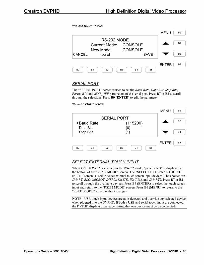
Crestron DVPHD High Definition Digital Video Processor
Operations Guide – DOC. 6545F High Definition Digital Video Processor: DVPHD • 63
“RS-232 MODE” Screen
RS-232 MODE Current Mode: CONSOLE New Mode: CONSOLECANCEL serial SAVE
B6
B7
B8
B9
MENU
ENTERB0 B1 B2 B3 B4 B5
SERIAL PORT The “SERIAL PORT” screen is used to set the Baud Rate, Data Bits, Stop Bits, Parity, RTS and XON_OFF parameters of the serial port. Press B7 or B8 to scroll through the selections. Press B9 (ENTER) to edit the parameter.
“SERIAL PORT” Screen
SERIAL PORT >Baud Rate (115200) Data Bits (8) Stop Bits (1)
B6
B7
B8
B9
MENU
ENTERB0 B1 B2 B3 B4 B5
SELECT EXTERNAL TOUCH INPUT When EXT_TOUCH is selected as the RS-232 mode, “panel select” is displayed at the bottom of the “RS232 MODE” screen. The “SELECT EXTERNAL TOUCH INPUT” screen is used to select external touch screen input devices. The choices are SMART, ELO, MICROT, DISPLAYMATE, WACOM, and SMART2. Press B7 or B8 to scroll through the available devices. Press B9 (ENTER) to select the touch screen input and return to the “RS232 MODE” screen. Press B6 (MENU) to return to the “RS232 MODE” screen without changes.
NOTE: USB touch input devices are auto-detected and override any selected device when plugged into the DVPHD. If both a USB and serial touch input are connected, the DVPHD displays a message stating that one device must be disconnected.

High Definition Digital Video Processor Crestron DVPHD
64 • High Definition Digital Video Processor: DVPHD Operations Guide – DOC. 6545F
“SELECT EXTERNAL TOUCH INPUT” Screen
SELECT EXTERNAL TOUCH INPUT SMART ELO
B6
B7
B8
B9
MENU
ENTERB0 B1 B2 B3 B4 B5
FRONT PANEL PASSWORD The “FRONT PANEL PASSWORD” screen is used to delete or enable a front panel password. If a valid password is saved, the front panel is locked until the correct password has been entered. If an empty string is saved, the password is disabled.
Press B7 or B8 to increase or decrease the underscored digit. Press B2 (DEL) to move the cursor back one step and delete the digit. Press B9 (ENTER) to move the cursor forward one step. Press B5 (SAVE) to confirm the password and return to the previous menu. Press B0 (CANCEL) or B6 (MENU) to return to the previous menu without change.
NOTE: A password must be four digits only. Passwords with less or more than four digits are ignored.
“FRONT PANEL PASSWORD” Screen
FRONT PANEL PASSWORD: Current: 1234 New: 12 CANCEL DEL SAVE
B6
B7
B8
B9
MENU
ENTERB0 B1 B2 B3 B4 B5
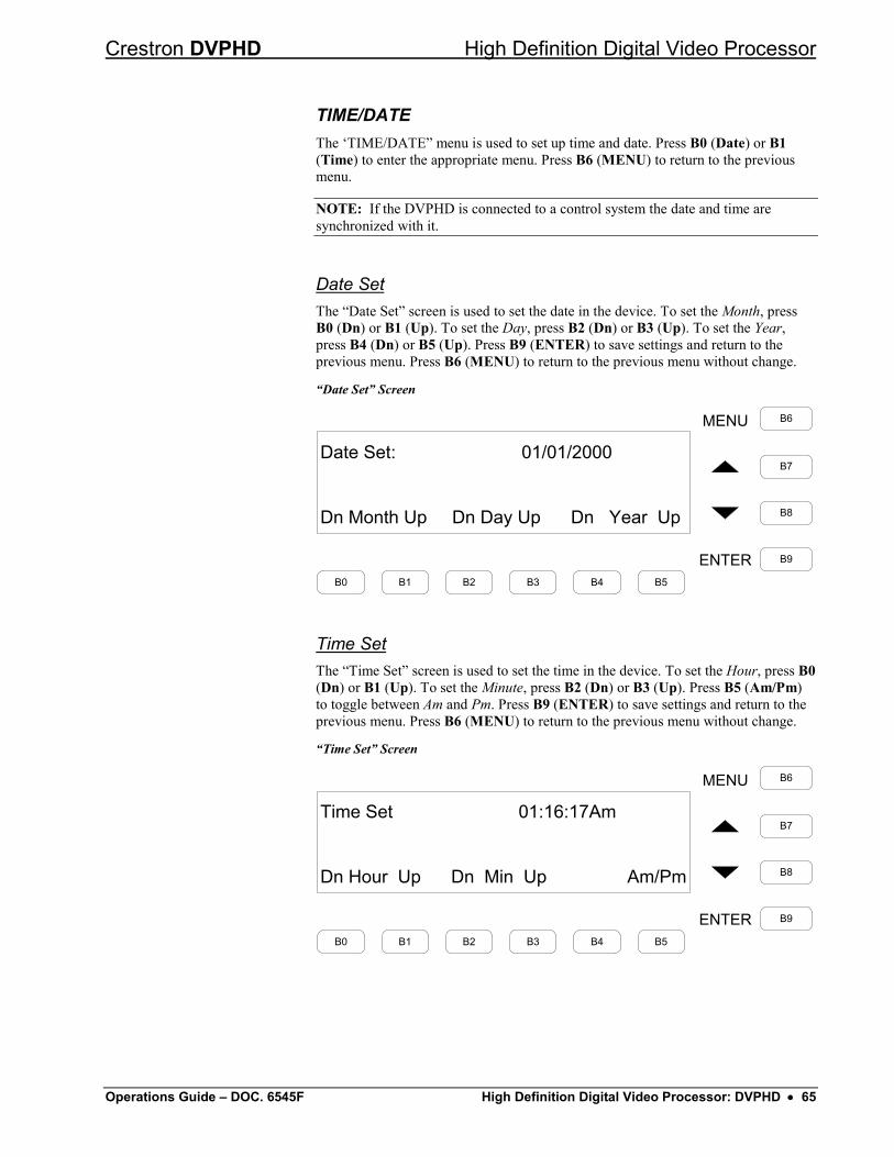
Crestron DVPHD High Definition Digital Video Processor
Operations Guide – DOC. 6545F High Definition Digital Video Processor: DVPHD • 65
TIME/DATE The ‘TIME/DATE” menu is used to set up time and date. Press B0 (Date) or B1 (Time) to enter the appropriate menu. Press B6 (MENU) to return to the previous menu.
NOTE: If the DVPHD is connected to a control system the date and time are synchronized with it.
Date Set The “Date Set” screen is used to set the date in the device. To set the Month, press B0 (Dn) or B1 (Up). To set the Day, press B2 (Dn) or B3 (Up). To set the Year, press B4 (Dn) or B5 (Up). Press B9 (ENTER) to save settings and return to the previous menu. Press B6 (MENU) to return to the previous menu without change.
“Date Set” Screen
Date Set: 01/01/2000 Dn Month Up Dn Day Up Dn Year Up
B6
B7
B8
B9
MENU
ENTERB0 B1 B2 B3 B4 B5
Time Set The “Time Set” screen is used to set the time in the device. To set the Hour, press B0 (Dn) or B1 (Up). To set the Minute, press B2 (Dn) or B3 (Up). Press B5 (Am/Pm) to toggle between Am and Pm. Press B9 (ENTER) to save settings and return to the previous menu. Press B6 (MENU) to return to the previous menu without change.
“Time Set” Screen
Time Set 01:16:17Am Dn Hour Up Dn Min Up Am/Pm
B6
B7
B8
B9
MENU
ENTERB0 B1 B2 B3 B4 B5
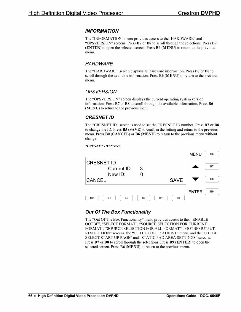
High Definition Digital Video Processor Crestron DVPHD
66 • High Definition Digital Video Processor: DVPHD Operations Guide – DOC. 6545F
INFORMATION The “INFORMATION” menu provides access to the ‘HARDWARE” and “OPSVERSION” screens. Press B7 or B8 to scroll through the selections. Press B9 (ENTER) to open the selected screen. Press B6 (MENU) to return to the previous menu.
HARDWARE The “HARDWARE” screen displays all hardware information. Press B7 or B8 to scroll through the available information. Press B6 (MENU) to return to the previous menu.
OPSVERSION The “OPSVERSION” screen displays the current operating system version information. Press B7 or B8 to scroll through the available information. Press B6 (MENU) to return to the previous menu.
CRESNET ID The “CRESNET ID” screen is used to set the CRESNET ID number. Press B7 or B8 to change the ID. Press B5 (SAVE) to confirm the setting and return to the previous menu. Press B0 (CANCEL) or B6 (MENU) to return to the previous menu without change.
“CRESNET ID” Screen
CRESNET ID Current ID: 3 New ID: 0 CANCEL SAVE
B6
B7
B8
B9
MENU
ENTERB0 B1 B2 B3 B4 B5
Out Of The Box Functionality The “Out Of The Box Functionality” menu provides access to the: “ENABLE OOTBF”, “SELECT FORMAT”, “SOURCE SELECTION FOR CURRENT FORMAT”, “SOURCE SELECTION FOR ALL FORMAT”, “OOTBF OUTPUT RESOLUTION” screens, the “OOTBF COLOR ADJUST” menu, and the “OTTBF SELECT START UP PAGE” and “STATIC PAD AREA SETTINGS” screens. Press B7 or B8 to scroll through the selections. Press B9 (ENTER) to open the selected screen. Press B6 (MENU) to return to the previous menu.
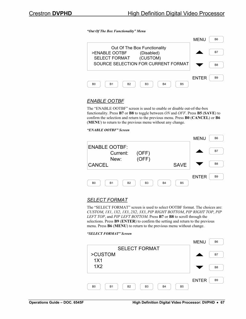
Crestron DVPHD High Definition Digital Video Processor
Operations Guide – DOC. 6545F High Definition Digital Video Processor: DVPHD • 67
“Out Of The Box Functionality” Menu
Out Of The Box Functionality >ENABLE OOTBF (Disabled) SELECT FORMAT (CUSTOM) SOURCE SELECTION FOR CURRENT FORMAT
B6
B7
B8
B9
MENU
ENTERB0 B1 B2 B3 B4 B5
ENABLE OOTBF The “ENABLE OOTBF” screen is used to enable or disable out-of-the-box functionality. Press B7 or B8 to toggle between ON and OFF. Press B5 (SAVE) to confirm the selection and return to the previous menu. Press B0 (CANCEL) or B6 (MENU) to return to the previous menu without any change.
“ENABLE OOTBF” Screen
ENABLE OOTBF: Current: (OFF) New: (OFF)CANCEL SAVE
B6
B7
B8
B9
MENU
ENTERB0 B1 B2 B3 B4 B5
SELECT FORMAT The “SELECT FORMAT” screen is used to select OOTBF format. The choices are: CUSTOM, 1X1, 1X2, 1X3, 2X2, 3X3, PIP RIGHT BOTTOM, PIP RIGHT TOP, PIP LEFT TOP, and PIP LEFT BOTTOM. Press B7 or B8 to scroll through the selections. Press B9 (ENTER) to confirm the setting and return to the previous menu. Press B6 (MENU) to return to the previous menu without change.
“SELECT FORMAT” Screen
SELECT FORMAT >CUSTOM 1X1 1X2
B6
B7
B8
B9
MENU
ENTERB0 B1 B2 B3 B4 B5
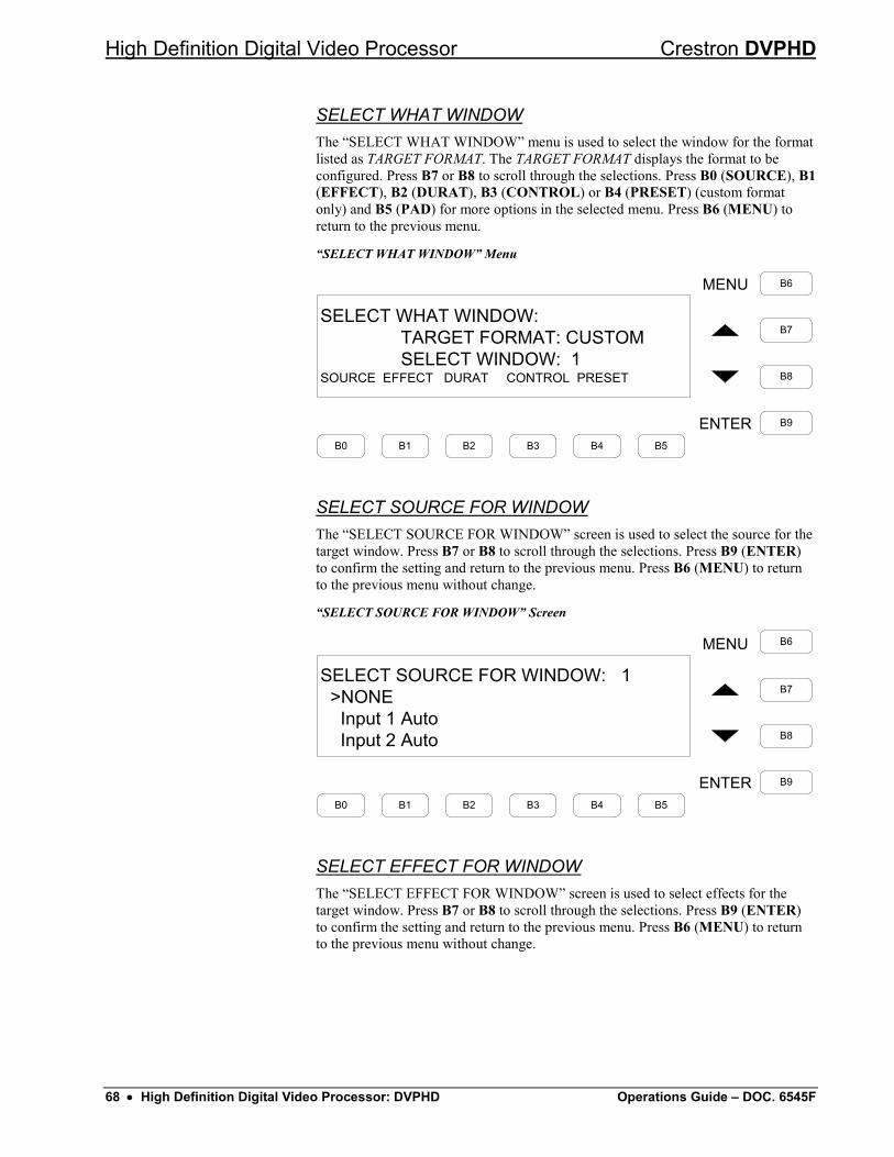
High Definition Digital Video Processor Crestron DVPHD
68 • High Definition Digital Video Processor: DVPHD Operations Guide – DOC. 6545F
SELECT WHAT WINDOW The “SELECT WHAT WINDOW” menu is used to select the window for the format listed as TARGET FORMAT. The TARGET FORMAT displays the format to be configured. Press B7 or B8 to scroll through the selections. Press B0 (SOURCE), B1 (EFFECT), B2 (DURAT), B3 (CONTROL) or B4 (PRESET) (custom format only) and B5 (PAD) for more options in the selected menu. Press B6 (MENU) to return to the previous menu.
“SELECT WHAT WINDOW” Menu
SELECT WHAT WINDOW: TARGET FORMAT: CUSTOM SELECT WINDOW: 1SOURCE EFFECT DURAT CONTROL PRESET
B6
B7
B8
B9
MENU
ENTERB0 B1 B2 B3 B4 B5
SELECT SOURCE FOR WINDOW The “SELECT SOURCE FOR WINDOW” screen is used to select the source for the target window. Press B7 or B8 to scroll through the selections. Press B9 (ENTER) to confirm the setting and return to the previous menu. Press B6 (MENU) to return to the previous menu without change.
“SELECT SOURCE FOR WINDOW” Screen
SELECT SOURCE FOR WINDOW: 1 >NONE Input 1 Auto Input 2 Auto
B6
B7
B8
B9
MENU
ENTERB0 B1 B2 B3 B4 B5
SELECT EFFECT FOR WINDOW The “SELECT EFFECT FOR WINDOW” screen is used to select effects for the target window. Press B7 or B8 to scroll through the selections. Press B9 (ENTER) to confirm the setting and return to the previous menu. Press B6 (MENU) to return to the previous menu without change.

Crestron DVPHD High Definition Digital Video Processor
Operations Guide – DOC. 6545F High Definition Digital Video Processor: DVPHD • 69
“SELECT EFFECT FOR WINDOW” Screen
SELECT EFFECT FOR WINDOW: 1 >VIDEO CUT VIDEO STRETCH NORTH VIDEO STRETCH NORTHWEST
B6
B7
B8
B9
MENU
ENTERB0 B1 B2 B3 B4 B5
SET DURATION FOR WINDOW The “SET DURATION FOR WINDOW” screen is used to set duration time for the target window. Press B7 or B8 to change the time for the target window. Press B5 (SAVE) to confirm the setting and return to the previous menu. Press B0 (CANCEL) or B6 (MENU) to return to the previous menu without change.
“SET DURATION FOR WINDOW” Screen
SET DURATION FOR WINDOW: 1 Current Duration: 2 New Duration: 2CANCEL SAVE
B6
B7
B8
B9
MENU
ENTERB0 B1 B2 B3 B4 B5
SELECT CONTROL FOR WINDOW Press B3 (CONTROL) on the “SELECT WHAT WINDOW” menu to open the “SELECT CONTROL FOR WINDOW” menu. A number of other screens can be accessed from this menu. The screens are: “ACTIVE WINDOWS” (custom format only), “SET ASPECT RATIO”, “SET VERTICAL POSITION” (custom format only), “SET HORIZONTAL POSITION” (custom format only), “SET VERTICAL SIZE” (custom format only), “SET HORIZONTAL SIZE” (custom format only), “SET Z ORDER” (custom format only), “SET WINDOW COLOR”, “SET TEXT COLOR”, and “SET TEXT JUSTIFY”. Press B7 or B8 to scroll through the selections. Press B9 (ENTER) to open the selected screen. Press B6 (MENU) to return to the previous menu.
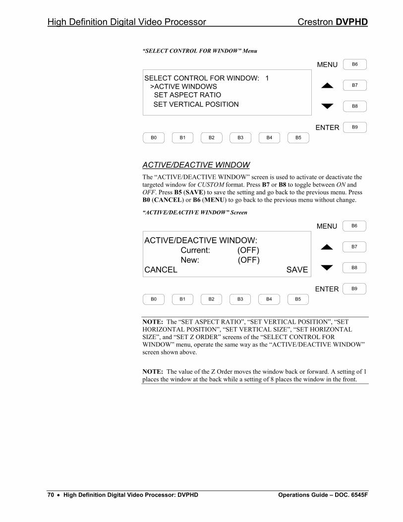
High Definition Digital Video Processor Crestron DVPHD
70 • High Definition Digital Video Processor: DVPHD Operations Guide – DOC. 6545F
“SELECT CONTROL FOR WINDOW” Menu
SELECT CONTROL FOR WINDOW: 1 >ACTIVE WINDOWS SET ASPECT RATIO SET VERTICAL POSITION
B6
B7
B8
B9
MENU
ENTERB0 B1 B2 B3 B4 B5
ACTIVE/DEACTIVE WINDOW The “ACTIVE/DEACTIVE WINDOW” screen is used to activate or deactivate the targeted window for CUSTOM format. Press B7 or B8 to toggle between ON and OFF. Press B5 (SAVE) to save the setting and go back to the previous menu. Press B0 (CANCEL) or B6 (MENU) to go back to the previous menu without change.
“ACTIVE/DEACTIVE WINDOW” Screen
ACTIVE/DEACTIVE WINDOW: Current: (OFF) New: (OFF)CANCEL SAVE
B6
B7
B8
B9
MENU
ENTERB0 B1 B2 B3 B4 B5
NOTE: The “SET ASPECT RATIO”, “SET VERTICAL POSITION”, “SET HORIZONTAL POSITION”, “SET VERTICAL SIZE”, “SET HORIZONTAL SIZE”, and “SET Z ORDER” screens of the “SELECT CONTROL FOR WINDOW” menu, operate the same way as the “ACTIVE/DEACTIVE WINDOW” screen shown above.
NOTE: The value of the Z Order moves the window back or forward. A setting of 1 places the window at the back while a setting of 8 places the window in the front.
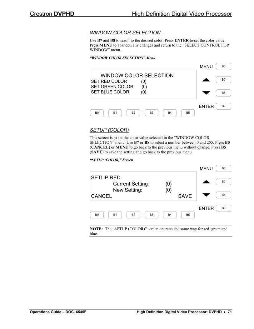
Crestron DVPHD High Definition Digital Video Processor
Operations Guide – DOC. 6545F High Definition Digital Video Processor: DVPHD • 71
WINDOW COLOR SELECTION Use B7 and B8 to scroll to the desired color. Press ENTER to set the color value. Press MENU to abandon any changes and return to the “SELECT CONTROL FOR WINDOW” menu.
“WINDOW COLOR SELECTION” Menu
WINDOW COLOR SELECTIONSET RED COLOR (0)SET GREEN COLOR (0)SET BLUE COLOR (0)
B6
B7
B8
B9
MENU
ENTERB0 B1 B2 B3 B4 B5
SETUP (COLOR) This screen is to set the color value selected in the “WINDOW COLOR SELECTION” menu. Use B7 or B8 to select a number between 0 and 255. Press B0 (CANCEL) or MENU to go back to the previous menu without change. Press B5 (SAVE) to save the setting and go back to the previous menu.
“SETUP (COLOR)” Screen
SETUP RED Current Setting: (0) New Setting: (0)CANCEL SAVE
B6
B7
B8
B9
MENU
ENTERB0 B1 B2 B3 B4 B5
NOTE: The “SETUP (COLOR)” screen operates the same way for red, green and blue.
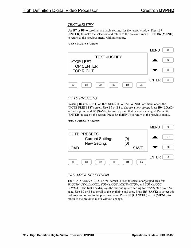
High Definition Digital Video Processor Crestron DVPHD
72 • High Definition Digital Video Processor: DVPHD Operations Guide – DOC. 6545F
TEXT JUSTIFY Use B7 or B8 to scroll all available settings for the target window. Press B9 (ENTER) to make the selection and return to the previous menu. Press B6 (MENU) to return to the previous menu without change.
“TEXT JUSTIFY” Screen
TEXT JUSTIFY >TOP LEFT TOP CENTER TOP RIGHT
B6
B7
B8
B9
MENU
ENTERB0 B1 B2 B3 B4 B5
OOTB PRESETS Pressing B4 (PRESET) on the” SELECT WHAT WINDOW” menu opens the “OOTB PRESETS” screen. Use B7 or B8 to choose a new preset. Press B0 (LOAD) to load a preset and B5 (SAVE) to save a preset that has been changed. Press B9 (ENTER) to access the screen. Press B6 (MENU) to return to the previous menu.
“OOTB PRESETS” Screen
OOTB PRESETS Current Setting: (0) New Setting: (0)LOAD SAVE
B6
B7
B8
B9
MENU
ENTERB0 B1 B2 B3 B4 B5
PAD AREA SELECTION The “PAD AREA SELECTION” screen is used to select a target pad area for: TOUCHOUT CHANNEL, TOUCHOUT DESTINATION, and TOUCHOUT FORMAT. The first line displays the current system setting for CUSTOM or STATIC page. Use B7 or B8 to scroll to the available pad area. Press B5 (SAVE) to select this pad area and return to the previous menu. Press B0 (CANCEL) or B6 (MENU) to return to the previous menu without change.

Crestron DVPHD High Definition Digital Video Processor
Operations Guide – DOC. 6545F High Definition Digital Video Processor: DVPHD • 73
“PAD AREA SELECTION” Screen
PAD AREA SELECTION: CUSTOM WINDOW Current Pad Area: (0) New Pad Area: (0)CANCEL SAVE
B6
B7
B8
B9
MENU
ENTERB0 B1 B2 B3 B4 B5
SELECT WHAT FORMAT The “SELECT WHAT FORMAT” screen is used to select OOTBF format. The choices are: CUSTOM, 1X1, 1X2, 1X3, 2X2, 3X3, PIP RIGHT BOTTOM, PIP RIGHT TOP, PIP LEFT TOP, and PIP LEFT BOTTOM. Press B7 or B8 to scroll through the selections. Press B9 (ENTER) to confirm the setting and return to the previous menu. Press B6 (MENU) to return to the previous menu without change.
“SELECT WHAT FORMAT” Screen
SELECT WHAT FORMAT: >CUSTOM 1X1 1X2
B6
B7
B8
B9
MENU
ENTERB0 B1 B2 B3 B4 B5
OOTBF OUTPUT RESOLUTION The “OOTBF OUTPUT RESOLUTION” screen is used to set the output resolution. Use B7 or B8 to scroll to the desired selection. Press B9 (ENTER) to make the selection and return to the previous menu.
“OOTBF OUTPUT RESOLUTION” Screen
OOTBF OUTPUT RESOLUTION: >1920 X 1200 @ 60Hz 640 X 400 @ 85Hz 640 X 480 @ 60Hz
B6
B7
B8
B9
MENU
ENTERB0 B1 B2 B3 B4 B5

High Definition Digital Video Processor Crestron DVPHD
74 • High Definition Digital Video Processor: DVPHD Operations Guide – DOC. 6545F
COLOR SELECTION The “COLOR SELECTION” menu is used to set the OOTBF color. Press B7 or B8 to scroll through the selections. Press B9 (ENTER) to open the selected screen.
NOTE: This menu allows changing the OOTBF background color of both static and custom pages.
“COLOR SELECTION” Menu
COLOR SELECTION: >RED GREEN BLUE
B6
B7
B8
B9
MENU
ENTERB0 B1 B2 B3 B4 B5
OOTBF SELECT START UP PAGE The “OOTBF SELECT START UP PAGE” screen is used to set the OOTBF default start up page. Press B7 or B8 to scroll through the selections. Press B5 (SAVE) to save the setting and return to the previous menu. Press B0 (CANCEL) or B6 (MENU) to return to the previous menu without change.
“OOTBF SELECT START UP PAGE” Screen
OOTBF SELECT START UP PAGE: Current Page: CUSTOM 0 New Page: CUSTOM 100
CANCEL SAVE
B6
B7
B8
B9
MENU
ENTERB0 B1 B2 B3 B4 B5

Crestron DVPHD High Definition Digital Video Processor
Operations Guide – DOC. 6545F High Definition Digital Video Processor: DVPHD • 75
PAD AREA SETTING The “PAD AREA SETTING” menu is used to set target pad area for: TOUCHOUT CHANNEL, TOUCHOUT DESTINATION, and TOUCHOUT FORMAT. Press B7 or B8 to scroll through the selections. Press B9 (ENTER) to open the menu. Press B6 (MENU) to return to the previous menu.
“PAD AREA SETTING” Menu
PAD AREA SETTING : >SELECT PAD AREA (1) TOUCHOUT CHANNEL TOUCHOUT DESTINATION
B6
B7
B8
B9
MENU
ENTERB0 B1 B2 B3 B4 B5
PAD AREA SELECTION The “PAD AREA SELECTION” screen is used to select a target pad area for: TOUCHOUT CHANNEL, TOUCHOUT DESTINATION, and TOUCHOUT FORMAT. The first line displays the current system setting for CUSTOM or STATIC page. Use B7 or B8 to scroll to the available pad area. Press B5 (SAVE) to select this pad area and return to the previous menu. Press B0 (CANCEL) or B6 (MENU) to return to the previous menu without change.
“PAD AREA SELECTION” Screen
PAD AREA SELECTION : STATIC WINDOW Current Pad Area: 1 New Pad Area : 1CANCEL SAVE
B6
B7
B8
B9
MENU
ENTERB0 B1 B2 B3 B4 B5
NOTE: The “SELECT TOUGHOUT CHANNEL”, “SELECT TOUCHOUT DESTINATION”, and “SELECT TOUCHOUT FORMAT” screens operate the same way as the “PAD AREA SELECTION” screen shown above.

High Definition Digital Video Processor Crestron DVPHD
76 • High Definition Digital Video Processor: DVPHD Operations Guide – DOC. 6545F
AUTODISCOVERY The “AUTODISCOVERY” screen is used to enable or disable the autodiscovery feature. Use B7 or B8 to toggle between Enabled and Disabled. Press B5 (SAVE) to confirm the setting and return to the previous menu. Press B0 (CANCEL) or B6 (MENU) to return to the previous menu without change.
“AUTODISCOVERY” Screen
AUTODISCOVERY: Current: (Disabled) New: (Disabled)CANCEL SAVE
B6
B7
B8
B9
MENU
ENTERB0 B1 B2 B3 B4 B5
ANNOTATION The “ANNOTATION” menu is used to access the “ENABLE ANNOTATION”, “CLEAR ANNOTATION”, “LIVE/FROZEN VIDEO”, “SET BRUSH”, “SET COLOR”, and “REMOTE OVERRIDE” screens. Press B7 or B8 to scroll through the selections. Press B9 (ENTER) to open the menu. Press B6 (MENU) to return to the previous menu.
NOTE: A video window must have a pad area assigned to it for annotation to function.
“ANNOTATION” Menu
ANNOTATION >ENABLE ANNOTATION (Disabled) CLEAR ANNOTATION LIVE/FROZEN VIDEO (Live)
B6
B7
B8
B9
MENU
ENTERB0 B1 B2 B3 B4 B5
ENABLE ANNOTATION The “ENABLE ANNOTATION” screen is used to enable or disable annotation. Press B7 or B8 to toggle between Enabled and Disabled. Press B5 (SAVE) to confirm the setting and return to the previous menu. Press B0 (CANCEL) or B6 (MENU) to return to the previous menu without change.
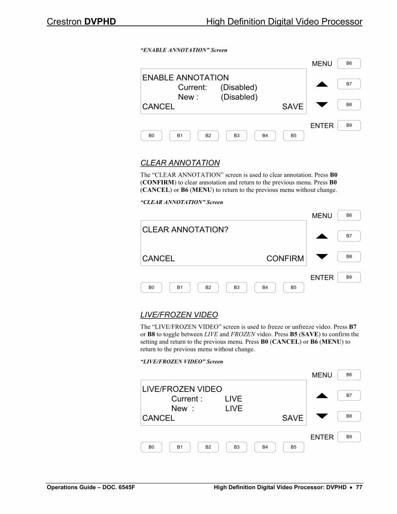
Crestron DVPHD High Definition Digital Video Processor
Operations Guide – DOC. 6545F High Definition Digital Video Processor: DVPHD • 77
“ENABLE ANNOTATION” Screen
ENABLE ANNOTATION Current: (Disabled) New : (Disabled)CANCEL SAVE
B6
B7
B8
B9
MENU
ENTERB0 B1 B2 B3 B4 B5
CLEAR ANNOTATION The “CLEAR ANNOTATION” screen is used to clear annotation. Press B0 (CONFIRM) to clear annotation and return to the previous menu. Press B0 (CANCEL) or B6 (MENU) to return to the previous menu without change.
“CLEAR ANNOTATION” Screen
CLEAR ANNOTATION?
CANCEL CONFIRM
B6
B7
B8
B9
MENU
ENTERB0 B1 B2 B3 B4 B5
LIVE/FROZEN VIDEO The “LIVE/FROZEN VIDEO” screen is used to freeze or unfreeze video. Press B7 or B8 to toggle between LIVE and FROZEN video. Press B5 (SAVE) to confirm the setting and return to the previous menu. Press B0 (CANCEL) or B6 (MENU) to return to the previous menu without change.
“LIVE/FROZEN VIDEO” Screen
LIVE/FROZEN VIDEO Current : LIVE New : LIVECANCEL SAVE
B6
B7
B8
B9
MENU
ENTERB0 B1 B2 B3 B4 B5
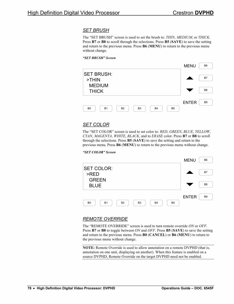
High Definition Digital Video Processor Crestron DVPHD
78 • High Definition Digital Video Processor: DVPHD Operations Guide – DOC. 6545F
SET BRUSH The “SET BRUSH” screen is used to set the brush to: THIN, MEDIUM, or THICK. Press B7 or B8 to scroll through the selections. Press B5 (SAVE) to save the setting and return to the previous menu. Press B6 (MENU) to return to the previous menu without change.
“SET BRUSH” Screen
SET BRUSH: >THIN MEDIUM THICK
B6
B7
B8
B9
MENU
ENTERB0 B1 B2 B3 B4 B5
SET COLOR The “SET COLOR” screen is used to set color to: RED, GREEN, BLUE, YELLOW, CYAN, MAGENTA, WHITE, BLACK, and to ERASE color. Press B7 or B8 to scroll through the selections. Press B5 (SAVE) to save the setting and return to the previous menu. Press B6 (MENU) to return to the previous menu without change.
“SET COLOR” Screen
SET COLOR: >RED GREEN BLUE
B6
B7
B8
B9
MENU
ENTERB0 B1 B2 B3 B4 B5
REMOTE OVERRIDE The “REMOTE OVERRIDE” screen is used to turn remote override ON or OFF. Press B7 or B8 to toggle between ON and OFF. Press B5 (SAVE) to save the setting and return to the previous menu. Press B0 (CANCEL) or B6 (MENU) to return to the previous menu without change.
NOTE: Remote Override is used to allow annotation on a remote DVPHD (that is, annotation on one unit, displaying on another). When this feature is enabled on a source DVPHD, Remote Override on the target DVPHD need not be enabled.
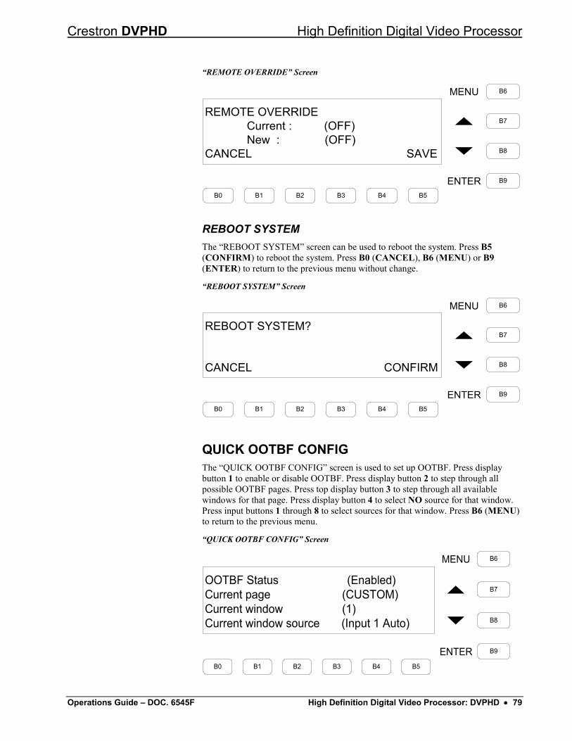
Crestron DVPHD High Definition Digital Video Processor
Operations Guide – DOC. 6545F High Definition Digital Video Processor: DVPHD • 79
“REMOTE OVERRIDE” Screen
REMOTE OVERRIDE Current : (OFF) New : (OFF)CANCEL SAVE
B6
B7
B8
B9
MENU
ENTERB0 B1 B2 B3 B4 B5
REBOOT SYSTEM The “REBOOT SYSTEM” screen can be used to reboot the system. Press B5 (CONFIRM) to reboot the system. Press B0 (CANCEL), B6 (MENU) or B9 (ENTER) to return to the previous menu without change.
“REBOOT SYSTEM” Screen
REBOOT SYSTEM?
CANCEL CONFIRM
B6
B7
B8
B9
MENU
ENTERB0 B1 B2 B3 B4 B5
QUICK OOTBF CONFIG The “QUICK OOTBF CONFIG” screen is used to set up OOTBF. Press display button 1 to enable or disable OOTBF. Press display button 2 to step through all possible OOTBF pages. Press top display button 3 to step through all available windows for that page. Press display button 4 to select NO source for that window. Press input buttons 1 through 8 to select sources for that window. Press B6 (MENU) to return to the previous menu.
“QUICK OOTBF CONFIG” Screen
OOTBF Status (Enabled)Current page (CUSTOM)Current window (1)Current window source (Input 1 Auto)
B6
B7
B8
B9
MENU
ENTERB0 B1 B2 B3 B4 B5

High Definition Digital Video Processor Crestron DVPHD
80 • High Definition Digital Video Processor: DVPHD Operations Guide – DOC. 6545F
Display and Input Front Panel Buttons
ENABLEOOTBF
PAGESELECT
WINDOWSELECT
NOINPUT
INPUT 1BNC
INPUT 2DVI
INPUT 3BNC
INPUT 4DVI
INPUT 5BNC
INPUT 6DVI
INPUT 7BNC
INPUT 8DVI
DISPLAY
INPUTS
ENTER/EXIT SETUP In the “ENTER/EXIT SETUP” screen, press B5 (SAVE) to save the setting and return to the previous menu. Press B0 (CANCEL) or B6 (MENU) to return to the previous menu without change.
“ENTER/EXIT SETUP” Screen
ENTER/EXIT SETUP Current : Setup page is on New : Exi t setup pageCANCEL SAVE
B 6
B 7
B 8
B 9
MENU
ENTERB 0 B 1 B 2 B 3 B 4 B 5

Crestron DVPHD High Definition Digital Video Processor
Operations Guide – DOC. 6545F High Definition Digital Video Processor: DVPHD • 81
Problem Solving
Troubleshooting The following table provides corrective action for possible trouble situations. If further assistance is required, please contact a Crestron customer service representative.
DVPHD Troubleshooting
TROUBLE POSSIBLE CAUSE(S) CORRECTIVE ACTION Device does not function.
Device is not receiving sufficient power.
Verify correct power to the device.
Incorrect firmware/software.
Update firmware/software versions as indicated in the Specifications section.
Incorrect cable connections.
Follow connection procedures in this guide and inspect connector pins.
No video output displayed.
Incorrect cable connections.
Verify connections and any adapters being used.
Output display resolution set incorrectly.
Set correct output display resolution.
DVPHD does not boot properly.
Firmware or program not properly loaded.
Use Toolbox to reload firmware or program.
Wrong source or video displayed.
Wrong VT Pro-e or SIMPL programs.
Verify correct programs.
VT Pro-e project not set up correctly.
Verify proper video set up for each displayed video window.
Front panel program not properly set up.
Verify proper video set up for each displayed video window.
Video from RGB source garbled or no output.
Incorrect cable connections.
Verify BNC and DVI cable connections.
Incorrect video effect in video window or video effect is different than expected.
VT Pro-e project not properly set up.
Verify video effect selected for the video window.
Front panel program not properly set up.
Verify video effect selected for the video window.
Wrong effect selected. Select the correct effect. Analog join value has been set.
Change analog join value to zero (0).
Mouse or touch screen does not work.
Incorrect touch settings. Ensure that the correct touch screen is selected in the front panel menus or by using Toolbox.
Incorrect calibration. Recalibrate touch screen.
(Continued on following page)

High Definition Digital Video Processor Crestron DVPHD
82 • High Definition Digital Video Processor: DVPHD Operations Guide – DOC. 6545F
DVPHD Troubleshooting (Continued)
TROUBLE POSSIBLE CAUSE(S) CORRECTIVE ACTION Incorrect displayed time and date.
Device recently rebooted.
The device does not have an internal real time clock. The time and date resets to 01/01/00 12:00:00 when rebooted.
HD sources do not display (Black Window), but other sources do.
The display device does not support HDCP.
Make sure the display is HDCP compliant and the device connected to the DVI or HDMI port on the display.
When HD sources are connected the QM output only displays a black screen
HDCP requires all non-encrypted outputs be disabled when displaying protected content.
None.
Check Network Wiring Use the Right Wire To ensure optimum performance over the full range of the installation topology, use
Crestron Certified Wire only. Failure to do so may incur additional charges if support is required to identify performance deficiencies because of using improper wire.
Calculate Power CAUTION: Use only Crestron power supplies for Crestron equipment. Failure to do so could cause equipment damage or void the Crestron warranty.
CAUTION: Provide sufficient power to the system. Insufficient power can lead to unpredictable results or damage to the equipment. Use the Crestron Power Calculator to help calculate how much power is needed for the system (www.crestron.com/calculators).
When calculating the length of wire for a particular Cresnet run, the wire gauge and the Cresnet power usage of each network unit to be connected must be taken into consideration. Use Crestron Certified Wire only. If Cresnet units are to be daisy chained on the run, the Cresnet power usage of each network unit to be daisy chained must be added together to determine the Cresnet power usage of the entire chain. If the unit is run from a Crestron system power supply network port, the Cresnet power usage of that unit is the Cresnet power usage of the entire run. The wire gauge and the Cresnet power usage of the run should be used in the following equation to calculate the cable length value on the equation’s left side.
Cable Length Equation
L = Length of run (or chain) in feetR = 6 Ohms (Crestron Certified Wire: 18 AWG (0.75 mm ))
or 1.6 Ohms (Cresnet HP: 12 AWG (4 mm ))P = Cresnet power usage of entire run (or chain)
2
2L < 40,000R x P
Where:
Make sure the cable length value is less than the value calculated on the right side of the equation. For example, a Cresnet run using 18 AWG Crestron Certified Wire and drawing 20 watts should not have a length of run more than 333 feet (101 meters). If Cresnet HP is used for the same run, its length could extend to 1250 feet (381 meters).

Crestron DVPHD High Definition Digital Video Processor
Operations Guide – DOC. 6545F High Definition Digital Video Processor: DVPHD • 83
NOTE: All Crestron certified Cresnet wiring must consist of two twisted pairs. One twisted pair is the 24 and G pair and the other twisted pair is the Y and Z pair.
Strip and Tin Wire When daisy chaining Cresnet units, strip the ends of the wires carefully to avoid nicking the conductors. Twist together the ends of the wires that share a pin on the network connector and tin the twisted connection. Apply solder only to the ends of the twisted wires. Avoid tinning too far up the wires or the end becomes brittle. Insert the tinned connection into the Cresnet connector and tighten the retaining screw. Repeat the procedure for the other three conductors.
Add Hubs Use of a Cresnet Hub/Repeater (CNXHUB) is advised whenever the number of Cresnet devices on a network exceeds 20 or when the combined total length of Cresnet cable exceeds 3000 feet (914 meters).
Reference Documents All documents mentioned in this guide are available at www.crestron.com/manuals.
List of Related Reference Documents
DOCUMENT TITLE 2-Series Control Systems Reference Guide Crestron DigitalMedia Design Guide Crestron e-Control Reference Guide
Further Inquiries To locate specific information or resolve questions after reviewing this guide, contact Crestron's True Blue Support at 1-888-CRESTRON [1-888-273-7876] or, for assistance within a particular geographic region, refer to the listing of Crestron worldwide offices at www.crestron.com/offices.
To post a question about Crestron products, log onto Crestron’s Online Help at www.crestron.com/onlinehelp. First-time users must establish a user account to fully benefit from all available features.
Future Updates As Crestron improves functions, adds new features and extends the capabilities of the DVPHD, additional information may be made available as manual updates. These updates are solely electronic and serve as intermediary supplements prior to the release of a complete technical documentation revision.
Check the Crestron Web site periodically for manual update availability and its relevance. Updates are identified as an “Addendum” in the Download column.

High Definition Digital Video Processor Crestron DVPHD
84 • High Definition Digital Video Processor: DVPHD Operations Guide – DOC. 6545F
Return and Warranty Policies
Merchandise Returns / Repair Service 1. No merchandise may be returned for credit, exchange or service without prior authorization from
Crestron. To obtain warranty service for Crestron products, contact an authorized Crestron dealer. Only authorized Crestron dealers may contact the factory and request an RMA (Return Merchandise Authorization) number. Enclose a note specifying the nature of the problem, name and phone number of contact person, RMA number and return address.
2. Products may be returned for credit, exchange or service with a Crestron Return Merchandise Authorization (RMA) number. Authorized returns must be shipped freight prepaid to Crestron, 6 Volvo Drive, Rockleigh, N.J. or its authorized subsidiaries, with RMA number clearly marked on the outside of all cartons. Shipments arriving freight collect or without an RMA number shall be subject to refusal. Crestron reserves the right in its sole and absolute discretion to charge a 15% restocking fee plus shipping costs on any products returned with an RMA.
3. Return freight charges following repair of items under warranty shall be paid by Crestron, shipping by standard ground carrier. In the event repairs are found to be non-warranty, return freight costs shall be paid by the purchaser.
Crestron Limited Warranty Crestron Electronics, Inc. warrants its products to be free from manufacturing defects in materials and workmanship under normal use for a period of three (3) years from the date of purchase from Crestron, with the following exceptions: disk drives and any other moving or rotating mechanical parts, pan/tilt heads and power supplies are covered for a period of one (1) year; touch screen display and overlay components are covered for 90 days; batteries and incandescent lamps are not covered.
This warranty extends to products purchased directly from Crestron or an authorized Crestron dealer. Purchasers should inquire of the dealer regarding the nature and extent of the dealer's warranty, if any.
Crestron shall not be liable to honor the terms of this warranty if the product has been used in any application other than that for which it was intended or if it has been subjected to misuse, accidental damage, modification or improper installation procedures. Furthermore, this warranty does not cover any product that has had the serial number altered, defaced or removed.
This warranty shall be the sole and exclusive remedy to the original purchaser. In no event shall Crestron be liable for incidental or consequential damages of any kind (property or economic damages inclusive) arising from the sale or use of this equipment. Crestron is not liable for any claim made by a third party or made by the purchaser for a third party.
Crestron shall, at its option, repair or replace any product found defective, without charge for parts or labor. Repaired or replaced equipment and parts supplied under this warranty shall be covered only by the unexpired portion of the warranty.
Except as expressly set forth in this warranty, Crestron makes no other warranties, expressed or implied, nor authorizes any other party to offer any warranty, including any implied warranties of merchantability or fitness for a particular purpose. Any implied warranties that may be imposed by law are limited to the terms of this limited warranty. This warranty statement supersedes all previous warranties.
Crestron software, including without limitation, product development software and product operating system software is licensed to Crestron dealers and Crestron Service Providers (CSPs) under a limited non-exclusive, non-transferable license pursuant to a separate end-user license agreement. The terms of this end user license agreement can be found on the Crestron Web site at www.crestron.com/legal/software_license_agreement.
Crestron DVPHD High Definition Digital Video Processor
Operations Guide – DOC. 6545F High Definition Digital Video Processor: DVPHD • 85
This page is intentionally left blank.

Crestron Electronics, Inc. Operations Guide – DOC. 6545F 15 Volvo Drive Rockleigh, NJ 07647 (2017262) Tel: 888.CRESTRON 08.13 Fax: 201.767.7576 Specifications subject to www.crestron.com change without notice.


