MOUNTING THE DISPLAY ............................................................................................................................ 5 CONNECTING TO THE SATLINK .................................................................................................................... 6
4. USING THE DISPLAY........................................................................................................................ 7
CONNECTIONS AND BUTTON LAYOUT ......................................................................................................... 7 FRONT PANEL BUTTON OPERATION ............................................................................................................. 7 SATLINK DISPLAY MENU DETAILS .............................................................................................................. 8 SATLINK DISPLAY MENU TREE LAYOUT ................................................................................................... 18 AUTOMATIC BACKUP OF SATLINK’S LOG TO SD CARD ............................................................................ 20 DEVICE PRIORITY ...................................................................................................................................... 20 CONFIGURING TO USE A MODEM ............................................................................................................... 20 VOICE OPERATION .................................................................................................................................... 24 SATLINK COMMUNICATOR AND THE DISPLAY ........................................................................................... 27
5. MAINTENANCE AND TROUBLESHOOTING ............................................................................ 31
Bringing the Benefits of Real-Time Data Collection to the World Sutron Corporation, 22400 Davis Drive, Sterling, Virginia 20164
3
1. Introduction
The Satlink display provides the user the ability to view and calibrate sensors on a Satlink, without needing a computer or PDA. It will also provide some indications if the Satlink has any error conditions. Starting with software version 2.xx, the display allows the user to fully setup a Satlink. Older versions (1.xx) do not allow users to fully setup a Satlink, but does provide a PC port to connect a PC or PDA to the Satlink, without the need to disconnect the display. Software version 1.xx can be upgraded to 2.xx (no hardware change required) using Satlink Communicator. The Display also provides a means of adding modem capabilities to the Satlink with either an internal modem, or an external RS-232 modem. This allows users to dial into the Satlink to make setup changes, download log files, or to just view sensor data. SD card support is available on all newer models of Satlink display. SD card support allows
Downloading Satlink's log to the card Saving Satlink's setup to the card Sending a setup to Satlink from the SD card Automatic backup of Satlink’s log to SD card Holding files for voice operation
Model Information
The label located on the back of the case will provide the unit serial number and model information. Currently, two models exist, they are: SL2-DISPLAY-1 Standard Display model SL2-DISPLAY-2 Display with an internal modem
Bringing the Benefits of Real-Time Data Collection to the World Sutron Corporation, 22400 Davis Drive, Sterling, Virginia 20164
4
2. Getting Started
Unpacking
The following items come with every Display that is shipped: One Satlink Display One RS-232 ribbon cable One two conductor cable for power One mounting bracket (installed at the factory) One manual (on CD-ROM) The internal modem version (-2) will also include a phone cable.
Handling
The following precautions should be observed with the Display: 1. When removing the ribbon cable DB-9's, grab the connector and not the cable.
These connectors are designed to fit tight without the need for securing screws, so pulling on the cable will cause damage to the cable.
2. Do not use harsh abrasive cleaners to clean the display. If the display becomes dirty, try first just wiping it with a soft slightly dampened cloth. If that does not work, use a mild soap/water solution.
3. If opening the case to make jumper changes, remove power (both the terminal block and the RS-232 cable to the Satlink). Then make sure to follow standard ESD practices to prevent damage to internal components.
Initial Checkout
The Display is fully tested at the factory so a quick operational check for shipping damage is all that is necessary. The only necessary item for a simple checkout is a power supply/battery. Simply apply power to the unit and see the backlight come on and the LCD show the software version. A green status LED will also come on and flash randomly as the processor does various tasks. The display shuts off after five minutes of inactivity. Pushing any button turns the display back on.
Bringing the Benefits of Real-Time Data Collection to the World Sutron Corporation, 22400 Davis Drive, Sterling, Virginia 20164
5
3. Installation
Mounting the Display
The Display comes with a mounting bracket that allows it to be attached directly onto the Satlink case. From the factory, the bracket is set to mount the display as shown below, if the Satlink is mounted with the RF connectors facing down, then rotate the bracket 90 degrees, to have it oriented for easy reading. To attach the display, make sure the wing nuts are loosened, snap the Display onto the Satlink, and then tighten the wing nuts.
The mounting bracket can also be removed, and the Display can be mounted directly to a wall or panel by using the four screw holes in the back. If mounting the display this way, do not use a longer screw than is needed, and take care when tightening the screws, as damage will occur to the internal board or LCD if the screw is installed too far into the case.
Bringing the Benefits of Real-Time Data Collection to the World Sutron Corporation, 22400 Davis Drive, Sterling, Virginia 20164
6
Connecting to the Satlink
Once the Satlink is mounted, connect the power cable (SDI-12 +12 and GND will work, if sdi sensors connected do not use a lot of current), RS-232 cable and, if applicable, an external modem or a phone line if using the -2 with internal modem. NOTE: The Display can run from the power supplied through pin 9 from the Satlink, but since it is only supplying +5 volts at a maximum of 150mA, the backlight will not be turned on unless +12 volts (battery) is supplied to the GND and +12 volts on the removable terminal block. +12 volts must also be supplied when using a modem. Sutron recommends that when using a modem, an external surge protection module be used on the phone line to protect the equipment that is connected to the phone line. Contact Sales or Customer Service for more information. Current phone protection models provided by Sutron are:
6461-1240-1T PC board, to mount to a grounded metal plate in an enclosure.
1311-1058 Enclosed model, with a grounding lug to wire to a ground rod.
Bringing the Benefits of Real-Time Data Collection to the World Sutron Corporation, 22400 Davis Drive, Sterling, Virginia 20164
8
Turn the Display on and off
To turn the display on, press any one of the six buttons. Once the Display is on, it will attempt to talk with Satlink, and get the current configuration of the Satlink. To turn the display off, press the off button once in the Satlink status menu. To get to the status menu, either press and hold the off button from any menu, or navigate using the arrow keys.
Adjust Display Contrast
No matter what menu item is currently selected, the contrast can be adjusted. To enter the contrast adjust menu, press and hold the up ▲ or down ▼ button until "CONTRAST" is in the top line and a bar is in the second line (NOTE: If the contrast is too low or high, the contrast won't initially be visible). Then press the up ▲ button to increase (darken) the contrast, press the down ▼ button to decrease (lighten) the contrast.
Satlink Display Menu Details
The menu has a tree structure, like directories in an operating system. Arrow keys UP, DOWN, LEFT and RIGHT allow navigating. Not all menus will allow navigation in all directions Pressing RIGHT will navigate to a sub-menu (assuming there is one). Pressing LEFT will go back to the parent menu. Pressing UP and DOWN will navigate among the menus on the same level. Here is a fictional menu tree, made up of seven menu items on three different levels: Top Menu 1
Mid Menu 1 Mid Menu 2
Sub Menu 1 Sub Menu 2
Mid Menu 3 Top Menu 2 Top Menu 1 and Top Menu 2 are both on the same level. Mid Menu 1 is a sub menu of Top Menu 1. For example, if in Mid Level Menu 2:
pressing UP will go to Mid Level Menu 1 pressing DOWN will go to Mid Level Menu 3 pressing LEFT or CANCEL will go to Top Level Menu 1 pressing RIGHT will go to Sub Menu 1
SET starts a change or confirms an action. CANCEL cancels a change or action. The CANCEL key is also labeled OFF. CANCEL also goes back levels ending UP at the quick status before going off. Hold CANCEL to go to the top of the menu. Hold UP or DOWN to change contrast setting. Hold SET turn on backlight Hints pop up when SET and > are available.
Bringing the Benefits of Real-Time Data Collection to the World Sutron Corporation, 22400 Davis Drive, Sterling, Virginia 20164
9
All changes to setup are password protected if a password is enabled. Disable the password by setting a blank password. Any change to setup will require that Satlink be stopped. If an attempt is made to make changes while Satlink is running or user is not logged in, the user will be prompted to stop Satlink and/or log in. Items in bold are the names of the menus. CAPITALIZED items are references to front panel keys. Menu names ending with an asterisk * are shown only if appropriate. For example, the System Errors* menu is shown only if Satlink has errors. Items in italics are data or settings shown on the display.
Indented items indicate sub menus.
This is the Satlink display menu tree:
System Errors* SATLINK MALFUNCTION Press Right for error details
Error Details Measurement(s) 1,2 have failed readings
Satlink Status Running, Both Tx On 2 Meas Active Press Set to change from running to stopped and vice-versa. Indicates whether Satlink is stopped or running. If running, the enabled transmissions are shown (Both Tx On, Sched Tx On, Randm Tx On, or Tx OFF) Second line shows the number of active measurements. Provides warning if Satlink is stopped (Satlink Stopped, Set Starts Satlink). Pressing CANCEL in this menu turns off the display. Station Name and Time Station Demo 2005/07/21 13:14:15 ? The station name is on line one. Press SET to change it. Line two shows the time. Time can never be set by user because Satlink uses a GPS for timekeeping. A ? following the time indicates GPS is not synced. If there is no ?, Satlink’s clock is synchronized to GPS, ensuring ultra-accurate timing. Live Reading 1* Stage 12.34 ft 2005/07/21 13:00:00 This is the last made reading of measurement 1, which the user named Stage. The time is the time the reading was made. Press RIGHT to see last 32 values, or press SET to perform continuous live readings. Once viewing live readings, press SET again to calibrate.
Bringing the Benefits of Real-Time Data Collection to the World Sutron Corporation, 22400 Davis Drive, Sterling, Virginia 20164
10
When calibrating, enter the value the sensor should read and press SET (this will result in a change to the offset of the measurement). Pressing CANCEL during calibration will abort the calibration.
Old Readings Stage: 32 Readings Down: Next Reading The Old Readings menu shows up to 32 of the last measurements made by Satlink. Press UP and DOWN to scroll through the readings. Each reading will come with a data value, quality, and time stamp (just like a live reading).
Live Reading 2* Precip BAD DATA 2005/07/21 13:00:00 Measurement 2 is shown after measurement 1. BAD DATA indicates a bad reading. The live readings of all active measurements will be shown. If a measurement is not setup as active, it will not appear. Live Reading 3* Live Reading 4* Live Reading 5* Live Reading 6* Live Reading 7* Live Reading 8* Live Reading 9* Live Reading 10* Measurement Setup and Status Measurement setup 3 meas active This menu tells how many measurements are active. Pressing RIGHT will go into the measurement setup menus.
Measurement 1 Setup Active Meas Stage Right shows details This is the measurement setup entry. Pressing RIGHT will navigate to measurement setup details. Pressing DOWN will move to the next measurement setup. This example indicates that measurement Stage is active.
Active Measurement Stage Active Press SET to change make the enable or disable the measurement. None of the following measurement settings are visible unless the measurement is active. Press SET to change any of the settings. Label* This is the name given to this measurement by the user. Press SET to edit the label (label is 7 characters long).
Bringing the Benefits of Real-Time Data Collection to the World Sutron Corporation, 22400 Davis Drive, Sterling, Virginia 20164
11
Measurement Type* What kind of measurement is this? Press SET to select one of the options: Tipping bucket | SDI-12 | Manual | 8400 DDR | Battery | Analog. The option selected here will determine which following menu items are visible. SDI-12 Address* Menu is visible only if SDI-12 is the measurement type. Press SET to edit the SDI-12 address. SDI-12 Command* Menu is visible only if SDI-12 is the measurement type. Press SET to edit. SDI-12 Parameter* Menu is visible only if SDI-12 is the measurement type. Press SET to edit. Analog Type* Menu is visible only if analog is the measurement type. Press SET to choose from: 0-5 | Ratiometric | 78mv | 625mv Analog Channel * Menu is visible only if analog is the measurement type. Press SET to choose from: 1-4 (if 0-5V or Ratiometric are the analog type) 1+,2- |3+,4- |3+,Vref (if 78mV or 625mV are the analog type) Analog Warmup Time* Menu is visible only if analog is the measurement type. Press SET to edit. Manual Entry* Menu is visible only if manual is the measurement type. Press SET to edit. 8400 DDR Sensor Name* Menu is visible only if 8400 DDR is the measurement type. Press SET to edit. Time (Offset)* Press SET to edit at what time this measurement will start. Interval* Press SET to edit how often to measure. Sampling* This menu will only work if Satlink is version 6.10 or newer. Press SET to edit how often to take a reading for an averaged result. Leave at 00:00:00 to disable averaging. Relative to Tx* Is the measurement offset relative to transmission time? Press SET to enable or disable. Min/Max* Press SET to enable or disable min/max processing. Send to Log*
Bringing the Benefits of Real-Time Data Collection to the World Sutron Corporation, 22400 Davis Drive, Sterling, Virginia 20164
12
Press SET to select whether the measurement will be logged. Right digits* Press set to change the number of significant right digits to transmit. Allowed numbers range from 0 to 7. Slope* Press set to edit the slope that the measurement reading is multiplied by. Offset* Press set to edit the offset that is added to the measurement reading. Alarm Status* Alarms Disabled Right shows details This menu will show whether alarms are enabled or not. Press RIGHT for alarm setup.
Hi-alarm Mode* Press set to choose from Off | TxIn | TxOut | TxBoth Low-alarm Mode* Press set to choose from Off | TxIn | TxOut | TxBoth Hi-ROC Alarm Mode* Press set to choose from Off | TxIn | TxOut | TxBoth Low-ROC Alarm Mode* Press set to choose from Off | TxIn | TxOut | TxBoth Hi-Alarm Threshold* Press set to edit the number. Low-Alarm Threshold* Press set to edit the number. Hi-ROC Alarm Threshold* Press set to edit the number. Low-ROC Alarm Threshold* Press set to edit the number. Deadband* Press set to edit the number.
Include Sched Tx* Press SET to select whether to have this measurement included in transmissions. Num Vals Sched Tx* This menu shows only if Include Sched Tx set to Yes. It determines how many readings to include in the transmission. Press SET to edit that number. Include Random Tx*
Bringing the Benefits of Real-Time Data Collection to the World Sutron Corporation, 22400 Davis Drive, Sterling, Virginia 20164
13
Press SET to select whether to have this measurement included in transmissions. Num vals Random Tx* This menu shows only if Include Sched Tx set to Yes. It determines how many readings to include in the transmission. Press SET to edit that number.
Measurement 2 Setup Active Meas Precip Right shows details This measurement and its sub menu are similar to measurement 1. Pressing RIGHT will enter the sub menu. Measurement 3 Setup Meas Sense03 is OFF Right shows details This measurement is disabled. Pressing RIGHT will go the Active menu where the measurement can be turned on. Measurement 4 Setup Measurement 5 Setup Measurement 6 Setup Measurement 7 Setup Measurement 8 Setup Measurement 9 Setup Measurement 10 Setup
Transmissions Status Transmissions Setup Sched ON. Random OFF This transmission menu indicates whether scheduled and/or random transmissions are enabled. Pressing RIGHT will go to the transmission setup sub menu.
Satellite ID Satellite ID 010570F2 This is the assigned ID for this station. It is used both for scheduled and random transmissions. Press set to change this hexadecimal number.
Scheduled Tx Enable Scheduled Tx On Press Set to disable This menu controls whether scheduled (self-timed) transmissions are enabled. Pressing SET will toggle the state. Pressing RIGHT will enter the scheduled transmission sub-menu.
None of the following are visible unless Scheduled transmissions are enabled Satellite Type* Press SET to choose the satellite type from: GOES 100 | GOES 300 | GOES 1200 | Meteosat MSG | Japan GMS | Fen Yun FY | ARGOS | SCD | ARGOS/SCD | INSAT
Bringing the Benefits of Real-Time Data Collection to the World Sutron Corporation, 22400 Davis Drive, Sterling, Virginia 20164
14
Channel* The channel the transmission is made on can be changed by pressing SET. Time (Offset)* When the transmission is to be made can be changed by pressing SET. Interval* Press SET to modify how often to make transmissions. Window Centering* Whether the transmission is to be centered inside the time window is controlled by pressing SET. Window Length* This menu shows only if Window Centering is enabled. Press SET to edit the time length of the window. Sensor Data Format What format the data collected by Satlink will be transmitted in can be changed by pressing SET. The options are SHEF | SHEFFIX | ASCII column | ASCII sensor | Pseudobinary. Append Settings Press RIGHT to view and edit the append options.
Battery voltage* Pressing SET will change whether Satlink appends its battery voltage to the transmission. Latitude/Longitude* Satlink can append its positional information if this setting is enabled by pressing SET. Station Name* This menu will work only if Satlink is version 6.10 or newer. Pressing SET will enable or disable this append option. Temperature* This menu will work only if Satlink is version 6.10 or newer. Pressing SET will enable or disable this append option. Fwd/Ref Power* This menu will work only if Satlink is version 6.10 or newer. Pressing SET will enable or disable appending the forward and reflected power of the last transmission.
INSAT 2nd ID* Unless India INSAT is the selected satellite type, this menu will not show. Press SET to edit this ID. SCD Channel* Unless ARGOS/SCD is the selected satellite type, this menu will not show. Press SET to edit the SCD channel.
Bringing the Benefits of Real-Time Data Collection to the World Sutron Corporation, 22400 Davis Drive, Sterling, Virginia 20164
15
Random Tx On Press Set to disable
This menu controls whether random transmissions are enabled. Pressing SET will toggle the state. Pressing RIGHT will enter the random transmission sub-menu.
None of the following are visible unless random transmissions are enabled Satellite Type* Press SET to choose the satellite type from: GOES 100 | GOES 300 | GOES 1200 | Meteosat MSG | Japan GMS | Fen Yun FY | ARGOS | SCD | ARGOS/SCD | INSAT Channel* The channel the transmission is made on can be changed by pressing SET. Time (Offset)* When the transmission is to be made can be changed by pressing SET. Normal Interval* Press SET to modify how often to make transmissions when not in alarm. Alarm Interval* Press SET to modify how often to make transmissions when in alarm. Burst Interval* Press SET to modify how often to make transmissions after entering alarm state. Number of Tx/Burst* The number of transmissions to be made after entering alarm state can be changed by pressing SET. Xxx Append Lat/Lon* Satlink can append its latitude and longitude if this setting is enabled by pressing SET.
Tx Force Press SET and system will prompt Tx will be made NOW!. Press SET again to have Satlink make an immediate transmission based on its scheduled transmission settings. A further prompt will ask Bypass GPS sync? If answered no, Satlink will synchronize its time and frequency to GPS prior to tx. If answered yes, Satlink will transmit without GPS sync. Once a transmission is initiated, the status will be updated on the display. Tx To Sutron Very similar to Tx Force, this menu will allow the sending of a transmission on Sutron’s test channel and ID.
General Setup Pressing RIGHT goes to the sub menu.
Bringing the Benefits of Real-Time Data Collection to the World Sutron Corporation, 22400 Davis Drive, Sterling, Virginia 20164
16
This menu shows only for Satlinks version 6.12 or newer. It accesses the password protection provided by Satlink. Press SET to change password. If Satlink is password protected, the currently granted access is shown. Read only access allows the user to view setup and data, but not to change it. Full access allows full access, and no access allows no access at all except to log in. Password Protection* Password protection: Disabled This menu shows only for Satlinks version 6.12 or newer. It accesses the password protection provided by Satlink. Press SET to change protection level. If “Read only access” is selected, a user without a password can see Satlink settings and data, but is not allowed to change setup or start/stop Satlink. If a user attempts to change setup, he is prompted for a password. The user must then enter the full access password in order to be granted access to change setup. If “Full access” is selected, than a user without a password cannot access Satlink at all. A user who logs in with the read access password will be granted read-only access but will not be allowed to change setup. Display Password Setup and Status* This menu is visible only for Satlinks version 6.11 or older. This password is internal to the Display. If logged in, press SET to change password and press RIGHT to Log Out. If not logged in, press SET to enter a password. If the password is blank, it is considered disabled. Station Name and Time The station name is on line one. Press SET to change it. Line two shows the time. Time can never be set by user because Satlink uses a GPS for timekeeping. A ? following the time indicates GPS is not synced. If there is no ?, Satlink’s clock is synchronized to GPS, ensuring ultra-accurate timing. Local Time Offset Press SET to change the local time offset (which is added to UTC time to result in Satlink’s internal time). The time format is +HH:MM where + is the sign (either – or +), HH is hours, and MM is minutes.
System Diagnostics System Diagnostics Satlink Batt 12.1V This menu shows a live reading of Satlink’s power supply voltage. Press RIGHT to enter the sub menu.
SDI Diagnostics Press RIGHT to access the SDI-12 menu.
Find SDI Devices Press SET to have Satlink search all SDI addresses for sensors. If a device is found, its reply will be shown. Hitting SET then will allow a change of the sensor’s SDI address. If a device is found, hitting DOWN will search for the next sensor.
Bringing the Benefits of Real-Time Data Collection to the World Sutron Corporation, 22400 Davis Drive, Sterling, Virginia 20164
17
Send SDI command Press SET to edit and send any SDI-12 command. The reply will be displayed.
Factory Defaults Press SET to change Satlink’s setup to defaults. Clear Satlink Status Press SET to clear Satlink’s status (including error conditions). Reset Failsafe Press SET to reset Satlink’s failsafe. Software Versions This menu shows the for Display and Satlink
SD Card* SD Card Operations Card detected This menu is available only on Satlink displays that have the optional SD card interface. The second line will show whether there is a card present and warn if that card is write protected. Pressing RIGHT will go into the sub menu.
Download log* Pressing SET will test the SD card and show log download options. The user can choose what data to download based on dates. Once the log download is started, the download progress is updated on the display: Press a key to abort 150/1500 Kbytes Please note that the partial log will still be saved to file even if a download is aborted by pressing a key or otherwise interrupted. This menu will be automatically shown if the SD card is inserted when the display is on. Get setup* Pressing SET will take the setup from Satlink and save it to the SD card. The file name will be based on the Satlink station name and the current time. Send setup* Pressing SET will allow the choice of Satlink setup file from the SD card. Use the arrow keys to navigate the directories and files on the SD card. Press SET to select displayed file and send it to Satlink. After sending the setup, please go to measurement and transmission setup menus to verify that Satlink is setup as intended. Auto backup log* For this menu to appear, not only must Satlink have an SD card plugged in, but files required for voice operation must be present. Use this menu to enable or disable the automatic backup of Satlink’s log to SD card. If voice files are not present, automatic backup is on by default. If voice files are present, backup will be off unless turned on using this menu.
Automatic log download* This menu is available only on Satlink displays that have the optional SD card interface. This is a menu that will be shown only when an SD card is inserted into a display that is in low power mode.
Bringing the Benefits of Real-Time Data Collection to the World Sutron Corporation, 22400 Davis Drive, Sterling, Virginia 20164
18
Upon inserting the card, the display will wake up and start a ten second countdown. It will show the countdown on the LCD: Auto Log Download Since last in 7 During the countdown, it will blink the yellow LED once a second. Abort the countdown and the log download by pressing any key. If not aborted, and once the ten seconds are up, the display will download the log since last download to the SD card. While the download is in progress, the LED will stay on; once completed, the LED turns off.
Satlink Display Menu Tree Layout
System Errors* Error Details
Satlink Status Station Name and Time Live Reading 1*
Old Readings Live Reading 2*
Old Readings .. Live Reading 10*
Old Readings Measurement Setup and Status
Measurement 1 Setup Active Label* Measurement Type* SDI-12 Address* SDI-12 Command* SDI-12 Parameter* Analog Type* Analog Channel * Analog Warmup Time* Manual Entry* 8400 DDR Sensor Name* Time (Offset)* Interval* Sampling* Relative to Tx* Min/Max* Send to Log* Right digits* Slope* Offset* Alarm Status* Hi-alarm Mode* Low-alarm Mode* Hi-ROC Alarm Mode* Low-ROC Alarm Mode*
Bringing the Benefits of Real-Time Data Collection to the World Sutron Corporation, 22400 Davis Drive, Sterling, Virginia 20164
19
Hi-Alarm Threshold* Low-Alarm Threshold* Hi-ROC Alarm Threshold* Low-ROC Alarm Threshold* Deadband* Include Sched Tx* Num Vals Sched Tx* Include Random Tx* Num vals Random Tx* Measurement 2 Setup .. Measurement 10 Setup
Transmissions Status
Satellite ID Scheduled Tx Enable Satellite Type* Channel* Time (Offset)* Interval* Window Centering* Window Length* Sensor Data Format Append Settings Battery voltage* Latitude/Longitude* Station Name* Temperature* Fwd/Ref Power* INSAT 2nd ID* SCD Channel* Random Tx Enable Satellite Type* Channel* Time (Offset)* Normal Interval* Alarm Interval* Burst Interval* Number of Tx/Burst* Append Lat/Lon* Tx Force Tx To Sutron
General Setup
Password Access* Password Protection* Display Password Setup and Status* Station Name and Time Local Time Offset
Bringing the Benefits of Real-Time Data Collection to the World Sutron Corporation, 22400 Davis Drive, Sterling, Virginia 20164
20
Clear Satlink Status Reset Failsafe Software Versions
SD Card*
Download log* Get setup* Send setup* Auto backup log*
Automatic Backup of Satlink’s Log to SD Card
If an SD card is left plugged into the Satlink Display, the Display will perform an automatic backup of Satlink’s log to the SD card. All the user needs to do is leave the SD card plugged in, and the Display will periodically download Satlink’s log and save it to a file on the SD card. This feature is available with software versions 3.20 and newer. If voice operation has been setup, automatic backup is disabled by default. To enable it, please use the front panel menu labeled Auto backup log. If voice files are not present, automatic backup is on and cannot be turned off except by removing the SD card. With an SD card in the Display, four hours after the user stops using the display, and every four hours afterwards, the Display will download logged data from Satlink and append it to a file. Once the file exceeds about 2MB, a new file will be started. The backup will work until the SD card gets full, at which point it stops downloading. NOTE: the Display needs to be able to talk to Satlink. If another device (such as a PC) is connected to the Display and has the communications port open, the Display will not be able to talk to Satlink and automatically backup Satlink’s log.
Device Priority
One role of the Display is to manage when and what gets to talk with the Satlink, because only one device can communicate with the Satlink at a time. The possible devices are the Display, a PC/PDA and a modem. The order of priority is (with 1 being the highest):
1. PC/PDA upgrading Satlink firmware (upgrade will not be interrupted) 2. Modem 3. PC/PDA connected to PC port 4. Display (user navigating with the front panel buttons)
What this means is that if a user is navigating the menus on the Display, and someone calls into the system via modem, then a message will appear stating that the Satlink is communicating with the modem and the user will be locked from doing anything until the modem has disconnected. Also, if a user were to connect a PC/PDA, and then try to use the buttons on the Display, the Display would state that the Satlink is communicating with a PC.
Configuring to use a Modem
Overview
This section covers the configurations needed for the Satlink Display to work with a modem. It also has a section for using the Xpert Voice modem, in data mode. See the "Satlink
Bringing the Benefits of Real-Time Data Collection to the World Sutron Corporation, 22400 Davis Drive, Sterling, Virginia 20164
21
Communicator and the Display" section for the basics of using the communicator program for dialing a Satlink.
Configure the Display
If using the -2 version of the display, with the internal modem, no jumper changes are needed. Simply connect the phone line to the TEL port. If using an external RS-232 modem, the jumper J5 must be set to RI (ring indicator), which is the factory default for this jumper. To see the current J5 jumper settings, remove the four screws on the back side of the case, leave the four screws holding the bracket to the back half of the case, and then separate the case into two halves. Once opened, look at the printed circuit board near the External Modem port and the RJ45 port and J5 is located between them. No other setting are needed for the Display to use the modem, the Display will automatically answer the phone when it detects a ring and then allow the Satlink to talk directly to the modem.
Bringing the Benefits of Real-Time Data Collection to the World Sutron Corporation, 22400 Davis Drive, Sterling, Virginia 20164
22
Modem Settings (AT commands)
When using a modem with the Display, it needs to be configured with the proper settings. These are not the settings needed on the PC modem, the PC modem should just be set to factory defaults, using the AT&F command. Below are the AT commands that must be sent to the modem to configure it. Use a terminal program such as HyperTerminal with the com port settings at 9600, 8, N, 1. If the -2 version with an internal modem is used, the internal modem is configured from the factory with these commands. If the internal modem stops working properly, these commands can be sent to the modem again by connecting the PC with the terminal program to the Satlink port and typing AT followed by the ENTER key several times to wake up the modem. If you are configuring the internal modem do the following:
1. Verify the Display is version 3.21 or newer (updates are at www.sutron.com) 2. Disconnect the cable between Satlink and Display. Disconnect any cables from the
Display’s PC, TEL, and MODEM jacks. 3. Power on the Display. 4. Press the OFF button once. Wait for Display to power off; it may take a while. 5. Connect a serial cable with a null modem from your PC to the Display port labeled
SATLINK. 6. Open Satlink Communicator (or you may use HyperTerminal) on the PC and connect to
the port. 7. If you press a button to wake the Display, it will say ‘Satlink connected to internal
modem.” If no internal modem is detected, it will say ‘Satlink connected to external modem.”
8. Issue AT commands via Communicator -> Comm Port -> Data to be Sent window (or you may use HyperTerminal)
Command Purpose AT&F Reset to Factory Defaults
ATS0=5 (S 'ZERO') Auto answer after five rings in case Display doesn't see the ring
ATE0 (E 'ZERO') Turn off command echo
AT&C1 Assert CD when a connection is made
AT&D2 Disconnect when DTR is dropped
ATQ0 (Q 'ZERO') Turn on command result codes
AT&W0 Store this profile in profile 0 (ZERO)
AT&Y0 Load profile 0 (ZERO) on power-up
Selecting Country Code (-2 model with internal modem)
Setting the modem’ s country code is done by with the +GCI command. To change to one of the 30 available countries, issue the “AT+GCI=n” command where “ n” is one of the two digit country codes.
Example: AT+GCI=3D<CR> Meaning: Change country code to France. OK Meaning: The modem has accepted the command and is now
configured for operation in France. AT+GCI?<CR> Meaning: Display current country code +GCI:3D Meaning: 3D (France is the current country selected). OK To view which countries are available in the modems firmware, enter
Bringing the Benefits of Real-Time Data Collection to the World Sutron Corporation, 22400 Davis Drive, Sterling, Virginia 20164
23
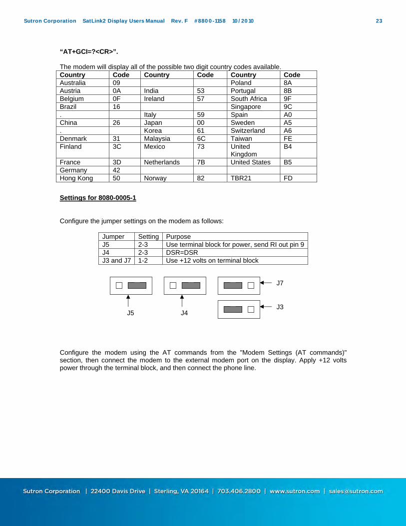
“AT+GCI=?<CR>”. The modem will display all of the possible two digit country codes available. Country Code Country Code Country Code Australia 09 Poland 8A Austria 0A India 53 Portugal 8B Belgium 0F Ireland 57 South Africa 9F Brazil 16 Singapore 9C . Italy 59 Spain A0 China 26 Japan 00 Sweden A5 . Korea 61 Switzerland A6 Denmark 31 Malaysia 6C Taiwan FE Finland 3C Mexico 73 United
Kingdom B4
France 3D Netherlands 7B United States B5 Germany 42 Hong Kong 50 Norway 82 TBR21 FD
Settings for 8080-0005-1
Configure the jumper settings on the modem as follows:
Jumper Setting Purpose J5 2-3 Use terminal block for power, send RI out pin 9 J4 2-3 DSR=DSR J3 and J7 1-2 Use +12 volts on terminal block
Configure the modem using the AT commands from the "Modem Settings (AT commands)" section, then connect the modem to the external modem port on the display. Apply +12 volts power through the terminal block, and then connect the phone line.
Bringing the Benefits of Real-Time Data Collection to the World Sutron Corporation, 22400 Davis Drive, Sterling, Virginia 20164
24
Voice Operation
Voice operation allows a person to dial into a Satlink station using a telephone. A properly equipped Satlink can speak information about the measurement data it has collected. Basically, a person calls the station with a phone, the station answers and speaks the weather data. The Satlink Display can speak the last data measured by Satlink. Only the last measured value of each measurement that is setup can be spoken. Older data is not accessible via voice. If one of Satlink’s measurements is in alarm, Display will speak alarm info to caller. Satlink Display can also speak any voice file that it has on the SD card. To use voice operation, a Satlink Display with an internal modem and SD card slot is required (SL2-DISPLAY-2). Additionally, voice files need to be placed on an SD card, and the SD card left inserted into Display. The voice files are in SatlinkVoice.zip which is downloaded with Satlink software (and placed into C:\Satink or a directory of the user’s choice during installation of Satlink software). The files can be placed on the SD card directly (using a PC) or remotely using Satlink Communicator. Voice files are described in detail in the sections below. Note that there is no ‘enable voice’ setting – leaving the SD card with the correct files inserted activates voice mode. The first version of Satlink Display to support voice is 3.37. This is what a voice sequence looks like:
Ring, ring Display picks up If the voice script file \Satlink\Voice\SL2Voice.ini is present, Display speaks “please
press #” o If caller presses # within five seconds, Display goes into voice mode
If either the voice script file is missing, or if the caller does not press #, Display goes into data mode (in which the user can use Communicator to access station setup and data).
If voice files are present, automatic backup is off by default. Backup can be turned on via the front panel menu item Auto backup log.
Voice Script File
The file SLVoice.ini is referred to as the voice script file. That file tells Satlink Display what files to speak when a call is placed. The file must be located in the \Satlink\Voice\ directory of the SD card. The file can be placed on the SD card directly (using a PC) or remotely using Satlink Communicator. The voice script file can contain the names of voice files that are to be spoken. It can also contain references to Satlink’s measurements. Additionally, the file can contain comments (which are not spoken but are there for the reader), numbers (which are spoken), and pauses. The file is parsed sequentially, line by line, and files are spoken in the order they are found. References to measurements: [M1] means speak measurement index 1, [M2] is for measurement 2, etc up to [M16]. Here’s an example of the contents of the voice script file SL2Voice.ini:
// This is a Satlink voice script file for Station #151 on Steep Creek. // It speaks the measurements that Satlink has been setup for. Welcome.vox To.vox
The voice file above will cause Satlink Display to first speak the file Welcome.vox. That file is supposed to be located on the SD card, in the \Satlink\Voice\Speech\ directory. The lines that start with // are for comments and are not spoken. The Display then speaks the file To.vox, followed by Station.vox, and Number.vox. [151] tells the Display to speak the number 151. Numbers with right digits (e.g. [12.345] are allowed) [Pause 2000] causes the Display to pause speech for 2 seconds. Display will then speak the file air temperature.vox. [M1] tells the display to speak the last measured value for Satlink’s measurement index one. If measurement one is in alarm, alarm information would be spoken. This is followed by the file Fahrenheit.vox, Humidity.vox, the last value for measurement index two, and so forth. If a file is called out in the script file but is not located on the SD card in the correct directory, Satlink Display will move on to speak the next file. Place only one file per line. Maximum length for a file name is 64 bytes.
Voice Speech Files
Voice speech files are the files that will be spoken by Satlink Display. The have a .vox extension. All the voice speech files must be placed in the \Satlink\Voice\Speech\ directory on the SD card. Sutron supplies basic voice speech files which can be downloaded from www.sutron.com. Files can be placed on the SD card directly (using a PC) or remotely using Satlink Communicator. You may create your own voice files. The speech files are binary data files containing audio data in Rockwell 4-bit ADPCM 8000hz mono format. These files are "headerless", meaning they have no information describing the content of the file, just sample data. Users can create these files using one of several aftermarket programs for the PC. One such program is "Vox Studio" by Xentec. This program allows the user to record speech using a microphone connected to the PC, and save it in the appropriate format. The program "Vox Studio", by Xentec, is available for download at: www.xentec.be. Note: the unregistered
Bringing the Benefits of Real-Time Data Collection to the World Sutron Corporation, 22400 Davis Drive, Sterling, Virginia 20164
26
version of this program limits the length of files to 5 seconds. As of this writing, a fee of $399 is required to register, which removes the limitation. When using Vox Studio or any other editing program, Sutron recommends trimming off the leading and trailing silence to help reduce the size of the file. We also recommend using the normalize function to adjust the volume of the recorded phrase.
Transferring Voice Files with Communicator
Satlink Communicator can be used to transfer voice files to the Display as long as an SD card has been left inserted. This means that it may not be necessary to visit a station to change voice operation. Satlink Communicator version 3.37 or newer is required to upload the voice files. Use the Satlink Display menu in Communicator and select option “Send Voice Script File” or option “Send Voice Speech Files”. When sending the voice speech files, you may select multiple files (tip: use Ctrl-A to select all files). The voice script file must be named SL2Voice.ini.
Bringing the Benefits of Real-Time Data Collection to the World Sutron Corporation, 22400 Davis Drive, Sterling, Virginia 20164
27
Satlink Communicator and the Display
Overview
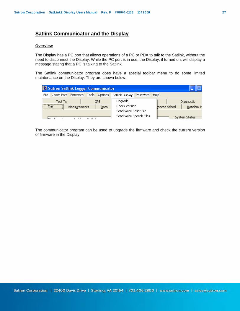
The Display has a PC port that allows operations of a PC or PDA to talk to the Satlink, without the need to disconnect the Display. While the PC port is in use, the Display, if turned on, will display a message stating that a PC is talking to the Satlink. The Satlink communicator program does have a special toolbar menu to do some limited maintenance on the Display. They are shown below:
The communicator program can be used to upgrade the firmware and check the current version of firmware in the Display.
Bringing the Benefits of Real-Time Data Collection to the World Sutron Corporation, 22400 Davis Drive, Sterling, Virginia 20164
28
The communicator program also has a new menu item for dialing a modem. This can be seen if using the "Show startup dialog" and by using the Comm Port toolbar and selecting modem.
Upgrading / Checking Display firmware Versions
In the event a new feature is added to the display functionality, or that a software bug is discovered, Sutron will normally provide an upgrade file via the Sutron web page (www.Sutron.com). To use this upgrade file:
1. Connect a pc to the PC port and run the Satlink logger communicator program. DO NOT UPGRADE WHEN CALLING INTO THE UNIT WITH A MODEM.
2. Select the Upgrade from the Satlink Display toolbar. 3. The communicator program will get the current firmware version and display it. If it
cannot, it will still allow an upgrade with a dialog stating, "Display did not respond...", click yes to proceed.
4. Select the appropriate upgrade file, or, if two files are provided (e.g. v1_xxmainSL2Dsp.upg and v1_xxbootSL2Dsp.upg) select both of them by holding the CTRL key and left clicking them.
5. Then the communicator program will proceed with the upgrade. 6. Do not disconnect the PC or power down the Display until the upgrade is completed.
To check the currently running version, select the Check version option under the Satlink Display toolbar.
Bringing the Benefits of Real-Time Data Collection to the World Sutron Corporation, 22400 Davis Drive, Sterling, Virginia 20164
29
Files named v2.xxmainSL2Dsp.upg are for the basic display, while v3_xxmainSL2DSD.upg are for the display that has SD card support. Note that it is possible to upgrade from version 1.xx (which does not allow the changing of Satlink’s setup) to version 2.xx by getting the latest software from www.sutron.com. However, it is not possible to do a software upgrade to get SD card support – new hardware is required for that.
Calling a Satlink Station with a Modem
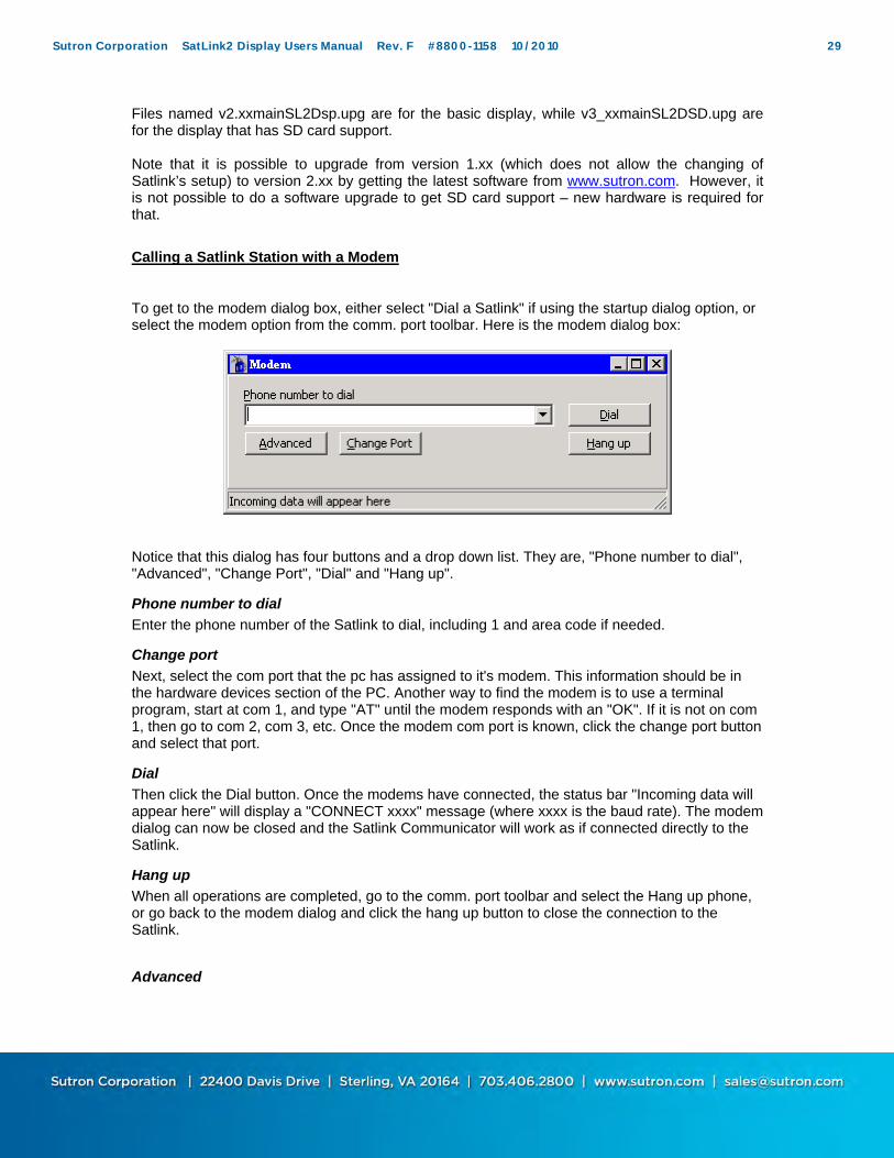
To get to the modem dialog box, either select "Dial a Satlink" if using the startup dialog option, or select the modem option from the comm. port toolbar. Here is the modem dialog box:
Notice that this dialog has four buttons and a drop down list. They are, "Phone number to dial", "Advanced", "Change Port", "Dial" and "Hang up".
Phone number to dial
Enter the phone number of the Satlink to dial, including 1 and area code if needed.
Change port
Next, select the com port that the pc has assigned to it's modem. This information should be in the hardware devices section of the PC. Another way to find the modem is to use a terminal program, start at com 1, and type "AT" until the modem responds with an "OK". If it is not on com 1, then go to com 2, com 3, etc. Once the modem com port is known, click the change port button and select that port.
Dial
Then click the Dial button. Once the modems have connected, the status bar "Incoming data will appear here" will display a "CONNECT xxxx" message (where xxxx is the baud rate). The modem dialog can now be closed and the Satlink Communicator will work as if connected directly to the Satlink.
Hang up
When all operations are completed, go to the comm. port toolbar and select the Hang up phone, or go back to the modem dialog and click the hang up button to close the connection to the Satlink.
Bringing the Benefits of Real-Time Data Collection to the World Sutron Corporation, 22400 Davis Drive, Sterling, Virginia 20164
30
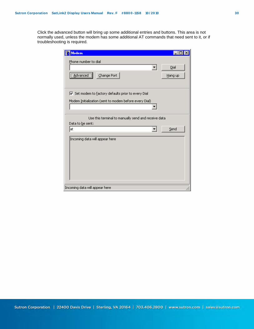
Click the advanced button will bring up some additional entries and buttons. This area is not normally used, unless the modem has some additional AT commands that need sent to it, or if troubleshooting is required.
Bringing the Benefits of Real-Time Data Collection to the World Sutron Corporation, 22400 Davis Drive, Sterling, Virginia 20164
31
5. Maintenance and Troubleshooting
Maintenance
The display has no special maintenance, just follow normal site maintenance, such as checking for frayed, loose wires.
Troubleshooting
Symptom Solutions No display Check the Display has power
Check Contrast settings
No communications with Satlink
Check that the Display has power Check the RS-232 cable from Satlink Port on the display to the Satlink Check that the Satlink has power If using a pc with Satlink communicator, ensure pc is connected to PC
port, and that the proper com port is selected. Backlight Does not turn on
Check that the display has +12 (battery) power
Modem won't answer
Check that the phone line is connected and that the phone line is working (connect handset to phone line and check for dial tone)
Bringing the Benefits of Real-Time Data Collection to the World Sutron Corporation, 22400 Davis Drive, Sterling, Virginia 20164
33
Appendix B: Sutron Customer Service Policy
Dear Customer:
Thank you for making the important decision to purchase Sutron equipment. All Sutron equipment is manufactured and tested to the highest quality standards as set by Sutron’s Quality Assurance Department. Our Customer Service Representatives have years of experience with equipment, systems, and services. They are electronic technicians with field and applications experience, not just with a technical background.
Customer Phone Support Customer Service Representatives routinely handle a wide variety of questions every day. If questions arise, please feel free to contact me or one of the Customer Service Representatives. We are available from 8:00 am to 5:00 pm Monday through Friday and will be happy to take your call. We can answer most sensor and interface questions on the first call. If we cannot quickly answer a question on an interface, we will work with you until we find a solution. Sometimes a problem is application related. Although we pride ourselves on handling 95% of application related questions over the phone, we maintain constant contact with our Integrated Systems Division and Engineering Division for additional assistance.
Introductory Training Training is an important part of the Sutron Customer Service philosophy. The Sutron training policy is simple---If you buy Sutron equipment, you get Sutron training! Without the proper training, you cannot take advantage of the benefits and advantages that Sutron equipment provides. We often supply on-site introductory training at your facility for no charge. You provide the classroom, students, equipment, and coffee---we'll provide the instructor.
On-Site Visits Of course not all problems can be fixed over the phone. Sometimes a customer needs an on-site technician to identify site related problems or troubleshoot a network. Sutron can provide these services at a reasonable cost. Call for details. If you would like to learn more about Sutron products email [email protected] Thanks again for your order, Paul Delisi Customer Service Manager Sutron Corporation
Bringing the Benefits of Real-Time Data Collection to the World Sutron Corporation, 22400 Davis Drive, Sterling, Virginia 20164
34
APPENDIX C WARRANTY INFORMATION
SUTRON MANUFACTURED EQUIPMENT
THE SUTRON CORPORATION WARRANTS that the equipment manufactured by its manufacturing division shall conform to applicable specifications and shall remain free from defects in workmanship and material for a period ending two years from the date of shipment from Sutron’s plant. Sutron’s obligation under this Warranty shall be limited to repair at the factory (22400 Davis Drive, Sterling, VA 20164), or at its option, replacement of defective product. In no event shall Sutron be responsible for incidental or consequential damages, whether or not foreseeable or whether or not Sutron has knowledge of the possibility of such damages. This warranty shall not apply to products that have been damaged through negligence, accident, misuse, or acts of nature such as floods, fires, earthquakes, lightning strikes, etc. Sutron’s liability, whether in contract or in tort, arising out of warranties or representations, instructions or defects from any cause, shall be limited exclusively to repair or replacement parts under the aforesaid conditions. Sutron requires the return of the defective electronic products or parts to the factory to establish claim under this warranty. The customer shall prepay transportation charges to the factory. Sutron shall pay transportation for the return of the repaired equipment to the customer when the validity of the damage claim has been established. Otherwise, Sutron will prepay shipment and bill the customer. All shipments shall be accomplished by best-way surface freight. Sutron shall in no event assume any responsibility for repairs or alterations made other than by Sutron. Any products repaired or replaced under this warranty will be warranted for the balance of the warranty period or for a period of 90 days from the repair shipment date, whichever is greater. Products repaired at cost will be warranted for 90 days from the date of shipment.
NON-SUTRON MANUFACTURED EQUIPMENT
The above Warranty applies only to products manufactured by Sutron. Equipment provided, but not manufactured by Sutron, is warranted and will be repaired to the extent of and according to the current terms and conditions of the respective equipment manufacturers.
REPAIR AND RETURN POLICY
Sutron maintains a repair department at the factory, 22400 Davis Drive, Sterling, VA 20164. Turn around time normally ranges from 10-30 days after Sutron receives equipment for repair. Call Customer Service at (703) 406-2800 for a Return Material Authorization (RMA) number. Return the defective equipment to the factory, transportation charges paid.
EXTENDED WARRANTY AND ON-SITE MAINTENANCE
Extended warranty and on-site maintenance contracts are available. Price quotations may be obtained from Sutron customer service representatives.


![2012 Knowledge Base & Application NotebookWith RS485 Control Channel SDI OUT ACT PWR SDI IN RS485 A+ B- GND HD-SDE-VDR SD/HD/3G-SDI Repeater [DVR/NVR Side] Including Link Power and](https://static.documents.pub/doc/80x56/610941634ce96f11174dc009/2012-knowledge-base-application-with-rs485-control-channel-sdi-out-act-pwr.jpg)

![Wireless Starter Kit Mainboard - Silicon Labs · vcom_enable pti0[0..2] vmcu gnd gnd gnd gnd vmcu vrf 5v 3v3 gnd vrf gnd gnd gnd gnd gnd usb_vbus usb_vreg usb_vbus 5v 5v_dbg …](https://static.documents.pub/doc/80x56/5ac0fbea7f8b9a4e7c8c7c14/wireless-starter-kit-mainboard-silicon-labs-pti002-vmcu-gnd-gnd-gnd-gnd-vmcu.jpg)


![GENRAL WIRING (GENRAL WIRING-1) · sdcd vdd(3r3v) sddat0 sd board gnd gnd gnd 3r3v 3r3v gnd maindak maindbk 5v [main dial] pbabk gnd pbbbk pclek pbbak rfl 3r3v 3r3v gnd gnd afl phoe](https://static.documents.pub/doc/80x56/5c000ba809d3f2c9268ca1e5/genral-wiring-genral-wiring-1-sdcd-vdd3r3v-sddat0-sd-board-gnd-gnd-gnd-3r3v.jpg)


