MREL warrants that the product is free from Manufacturer=s defects for a period of two (2) years from thedate of shipment to the Customer. This Warranty covers all parts and labour.
MREL does not warrant that the product will meet the Customer's requirements or that it will operate in thecombinations which may be selected for use by the Customer.
MREL does not and cannot warrant the performance or results that may be obtained by using the product.Accordingly, the product and its documentation are sold "as is" without warranty as to their performance,merchantability, or fitness for any particular purpose. The entire risk as to the results and performance of theproduct is assumed by the Customer.
Windows is a registered trademark of Microsoft Corporation. All other brand and product names aretrademarks or registered trademarks of their respective companies.
Copyright 1999, MREL Specialty Explosive Products Limited. This document and accompanying MiniTrapII
Software supersede any earlier releases.
All Rights Reserved. Reproduction or adaptation of any part of this documentation or Software without writtenpermission of the Copyright owner is unlawful.
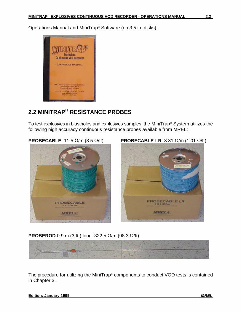
Congratulations on your purchase of the MiniTrap . The MiniTrap is an explosivesII II
continuous velocity of detonation (VOD) recorder which operates under the extremetemperatures, weather conditions, dust and rugged environments typical of the miningindustry world-wide. It is a stand-alone portable field system providing the capability tostore large amounts of VOD data. No other comparable VOD system is as easy to use asthe MiniTrap .II
The MiniTrap is supplied with MiniTrap Software to easily retrieve, graphically display,II II
analyse and print the VOD data recorded by the MiniTrap . The Software runs underII
Microsoft Windows, which allows incorporation of MiniTrap graphics into Windows word-II
processors and/or the export of MiniTrap data into Windows spreadsheets.II
This Operations Manual serves as a reference for the operation of the MiniTrap . TheII
Manual details how to operate the hardware and software and describes the fieldapplications of the system for recording the continuous VOD of explosives samples andexplosives down-the-hole, as well as the procedure for recording the delay times betweenblastholes and explosive decks to 1 microsecond accuracy.
1.2 SAFETY FIRST
The MiniTrap is easily operated. However, to monitor the VODs of explosives, its use inII
the field requires an operator who has been suitably trained and who is experienced inworking with explosives and on blast sites. The normal rules of safety apply whenworking with explosives. Persons not trained and authorized to handle explosives inblasting operations therefore should not attempt to utilize the MiniTrap for explosives VODII
measurements.
The MiniTrap provides a low voltage and extremely low current (less than 50 mA) to theII
probes within the explosives. This low excitation signal allows the MiniTrap to be usedII
without fear of initiating the explosives or detonators.
Due to the inherent hazards of blasting during electrical storms and the possibility of suchelectrical interference causing false trigger signals to the MiniTrap , it is not recommendedII
to blast during electrical storms. This is standard policy at most blasting operations.
1.3 TECHNICAL BACKGROUND - THE RESISTIVE WIRE TECHNIQUE
The MiniTrap is capable of monitoring the continuous VOD profile along the entire lengthII
of an explosives column. It can measure VODs of relatively short samples of explosivessuch as cast primers or sticks of explosives, and of explosives loaded down-the-hole insurface and underground blasts in single and multiple holes.
The MiniTrap uses the proven continuous resistive wire technique for monitoring VODs.II
A probe of known linear resistance (ie: S/m or S/ft) is placed or loaded axially in theexplosive column. For monitoring samples of explosives, the probe is a rigid PROBERODand for monitoring explosives down-the-hole, the probe is flexible PROBECABLE orPROBECABLE-LR. The MiniTrap provides a regulated constant excitation signal to theII
probe. It also monitors the voltage across the probe.
As the detonation head of the explosive consumes the probe, the resistance of the probedecreases in proportion to the decreasing length of the probe. The MiniTrap records theII
resulting decrease in voltage across the probe with time. The MiniTrap SoftwareII
automatically converts the data to a graph of distance versus time. The slope of thedistance versus time graph at any position is the VOD of the explosive at that position.The MiniTrap Software has a software tool for automatically calculating and displayingII
the VOD of the explosive at any location chosen by the operator, as well as a software toolfor automatically calculating and displaying the delay time between holes or decks ofexplosives chosen by the operator.
1.4 MINITRAP APPLICATIONSII
The MiniTrap monitors the continuous VODs in explosives samples and explosives down-II
the-hole with unmatched cost effectiveness and ease of use. Applications include:
EXPLOSIVE SAMPLES:$ Test the quality, consistency, and reliability of explosives to meet quality control
standards set for the explosive.$ Measure the continuous VOD in any charge diameter, unconfined in cardboard tubes
or confined in schedule 40 steel pipe.$ Determine the critical diameter and critical density for an explosive.$ Determine the gap sensitivity of explosives.$ Measure the timing accuracy of detonators.$ Measure the continuous VOD of primers.$ Determine the minimum primer size for any explosive by measuring run-up velocities.
EXPLOSIVES DOWN-THE-HOLE:$ Measure the continuous VOD in any hole diameter.$ Measure the continuous VOD in multiple holes per blast.$ Determine whether full detonation, low order detonation or failure occurred in the
explosive column and where this occurs in the explosive column.
$ Check VOD against manufacturer's specifications in full scale blasting environments.$ Determine the effects of detonating cord downlines on explosives. $ Determine the minimum primer size for any explosive by measuring run-up velocities in
full scale blasting environments.$ Measure the timing accuracy of detonators in full scale blasting environments.$ Measure the effects of water, drill cuttings, rocks etc... trapped within the explosive
column.$ Determine the minimum length of explosive column to use as a deck considering the
ingress of stemming and drill cuttings, water pick-up etc... and the explosive run-uprequirements.
$ Determine the correct length and type of material to use as stemming between decksof explosives to ensure that sympathetic detonation or explosive desensitization doesnot occur.
The MiniTrap has an internal NiCad rechargeable battery and is supplied with an auto-II
switching 110/220 VAC Charger. The MiniTrap is shipped from MREL fully charged.II
Since some time may elapse before the MiniTrap is actually put in use, the MiniTrap mayII II
not be fully charged the first time it is used. Full operating time will be obtained when theMiniTrap is recharged.II
TESTING THE MINITRAP POWER STATUSII
1. Disconnect the Charger from the MiniTrap at the CHARGER/DC IN connector on theII
MiniTrap .II
2. Turn MiniTrap power ON.II
3. Press and hold the POWER STATUS button. This can be done at any time during theoperation of the MiniTrap .II
4. The LED display shows the energy remaining in the internal rechargeable battery. F = fully charged (approximately 24 hours of operation time remain); 9 = 90% of fullcharge; 8 = 80% of full charge etc...
5. When L is displayed, the internal battery requires recharging. Do not conduct anyadditional VOD tests. Note: If the power is left ON, within 1-2 hours the MiniTrap willII
turn itself off to prevent complete discharge of the internal battery. The VOD data inthe permanent memory are never at risk of being lost.
6. Turn MiniTrap power OFF.II
RECHARGING THE MINITRAPII
1. Turn MiniTrap power OFF.II
2. Connect the Charger between the CHARGER/DC IN connector on the MiniTrap andII
the 110 VAC or 220 VAC mains. Full recharging takes 2 hours. The internal battery
cannot be overcharged.3. Test the MiniTrap Power Status as detailed above.II
OPERATING THE MINITRAP FROM AC POWERII
The MiniTrap can be operated from 110/220 VAC power. Contact MREL to request theII
optional MINITRAP AC ADAPTOR KIT.II
OPERATING THE MINITRAP FROM EXTERNAL DC POWERII
The MiniTrap can be operated from external 12 VDC sources. Contact MREL to requestII
the optional MINITRAP EXTERNAL DC ADAPTOR KIT.II
2.4 SPECIFICATIONS OF THE MINITRAPII
Number of Channels 1 channel.
Resolution 12 bits, 1 part in 4,096.
Recording Rate 1 MHz.
Recording Time 1,049 ms total recording time (262 ms pre-trigger and 787 ms post-trigger).@ 1 MHz
Trigger Modes User selectable: Internal VOD signal level or external trigger wire.
Power Internal rechargeable NiCad (not sealed lead/acid) battery which provides 24 hours of active operation on afull charge. The MiniTrap has a non-volatile memory so that the data are stored securely, regardless of theII
status of the internal battery. Full battery recharging takes 2 hours. Can be operated from 110/220 VAC mainsor from an external 12 VDC source with optional MiniTrap accessories. II
Field Settings - Menus The MiniTrap operates without the need for field settings or complex menus. The basic MiniTrap operatingII II
procedure is: connect the VOD signal wire to the BNC input connector labeled PROBE, turn the MiniTrapII
power on, press the NEXT TEST button, press the START button and walk away. When the explosive fires,the data are automatically recorded by the MiniTrap . II
System Components MiniTrap , Battery Charger (auto-switching 110/220 VAC), Communications Cable, Operations Manual,Provided Windows Software, all in one Carrying Case the size of a 35 mm camera bag.
II
Size and Weight MiniTrap : 23.5 x 19.7 x 11.4 cm (9.25 x 7.75 x 4.5 in.) 2.0 kg (4.4 lbs.)II
MiniTrap System in Carrying Case: 31.8 x 26.7 x 22.9 cm (12.5 x 10.5 x 9.0 in.) 4.0 kg (8.8 lbs.)II
Environmental Operates at -40 to +80 C (-40 to +185 F). Snow, rain, dust and sand proof. System in Carrying Case is dropN N N N
proof from at least a 1 m (3 ft.) height.
PC Connection After the test, the MiniTrap connects to the computer=s parallel (LPT1) printer port to allow downloading of dataII
to the computer faster than RS232 communications allow.
Software MiniTrap Software for Windows 3.1x and 32 bit Windows >95. Provides fast downloading of data from theII
MiniTrap to the computer and automatically displays a graph of DISTANCE versus TIME. All SoftwareII
operations are Apoint and click@. Unlimited graphical zoom on graphs and creation of annotated sub-graphs.VOD and hole/deck delay time analysis of any parts of the VOD graph. Annotating, printing, saving and exportof graphs and data to other Windows applications. The MiniTrap Software is based upon MREL=s provenII
DataTrap-VOD and MiniTrap Software in use around the world. User selectable: Metric or Imperialmeasurement units.
VOD Excitation and The MiniTrap automatically adjusts its excitation voltage for the maximum 12 bit resolution across the VODSafety probe. All VOD operating parameters are recorded by the MiniTrap with no requirement for additional
II
II
instruments. The MiniTrap is physically unable to output more than 50 mA of current to a VOD probe. ThereII
are no Acurrent limiting automatic fault checking systems@ to potentially fail.
VOD Probes A complete line of VOD probes are available from MREL to record the VODs of small explosives samples tomultiple holes in large opencast blasts. The MiniTrap can record VODs across PROBECABLE-LR (resistanceII
Care must be taken to select a good site for detonation and VOD recording of explosivesamples. If convenient, permanent test sites may be constructed. A pit surrounded by anearth wall suffices as a simple detonation site. A similarly protected shelter for theMiniTrap and personnel can be constructed some distance away. The distance willII
depend on the amount of explosive to be detonated at one time and whether theexplosives are confined in steel pipe. Ensure that the area is well demarcated and thataccess to the hazardous area is restricted.
If samples of explosives are to be detonated at an unprepared site then the operator mustbe careful when deciding upon what type of ground the charges are to be placed. Avoidplacement on ground with stones, rubble or anything that is likely to turn into a projectile.The best surfaces are fines, sand or tailings.
It is always good practice to have maximum control over the time of firing of the test andtherefore safety fuse initiation is not recommended. Electric or shock tube initiation is bestwith the detonator either initiating the sample of explosives or initiating the primer/boosterin the explosives sample. For site specific recommendations, contact MREL.
3.2 TESTING SAMPLES OF EXPLOSIVES - PROBE SETUP
The equipment and supplies required to conduct VOD tests on samples of explosives are:$ MiniTrap System.II
$ PROBERODs (rigid resistive probes) - one (1) per test.$ Coaxial cable (type RG-58 is recommended) - sufficient length to run between the
MiniTrap location and the explosives.II
$ Wire cutters and electrical tape.$ Explosives, detonators and shot exploder.
The procedure for preparing a VOD test is as follows:1. Demarcate the charge detonation area.2. Place the MiniTrap in a protective shelter or at a safe distance away from theII
detonation area. (This distance may be closer than what is considered safe for theoperator. When set up, the MiniTrap does not require an operator to collect the data;II
it collects the data without operator assistance.)3. Run a length of coaxial cable from the MiniTrap to the detonation area with enoughII
excess length to compensate for cable shortening or cable damage from each test.Shorter lengths of coaxial cable may be connected together using the wire cutters andelectrical tape. A male BNC connector should be attached to the end of the coaxialcable at the MiniTrap . A convenient BNC Adaptor has been supplied with theII
MiniTrap System for this purpose. It can be connected to the coaxial cable using theII
4. For quality control purposes, select and test the resistance of a rigid PROBEROD withan ohmmeter or blaster=s galvanometer. Do not use the PROBEROD if the ProbeResistance is outside the range of 295 to 305S. MREL will replace any out ofspecification PROBERODs.
5. Insert a rigid PROBEROD axially in the sample of explosives at the opposite end fromwhere the detonator will be placed. If bulk explosives are being tested in paper, plastic or steel pipes, and the pipes aresealed at both ends, make a small central hole to allow the PROBEROD to be inserted.If a measurement of run-up to detonation is required, ensure that the PROBEROD ispushed well into the explosives so that it reaches the position of the detonator orprimer. If the PROBEROD reaches the primer or protrudes past it, the effect of theprimer will be recorded by the MiniTrap . The same holds true for cartridges ofII
explosives.To test the VOD of detonation cord, tape the detonation cord along the entire lengthof the PROBEROD.
6. Note the Unit Resistance of the probe by reading the value in S/m or S/ft from thefactory label on the PROBEROD. Note the S/m value if the VOD is to be reported inm/s. Note the S/ft value if the VOD is to be reported in ft/sec. The Unit Resistance willbe requested later by the MiniTrap Software (Section 4.3). II
7. Connect the PROBEROD to the coaxial cable using the wire cutters and electrical tape.Do not be concerned with the polarity of the connection.
8. At the MiniTrap , connect the coaxial cable to the PROBE connector on the outside ofII
the MiniTrap .II
9. The probe setup aspects of the test are complete. The blaster can now place thedetonator and connect it to the shot exploder per standard procedures. The MiniTrapII
can now be set up to record the test (Section 3.5).
The equipment and supplies required to conduct VOD tests on explosives down-the-holeare:$ MiniTrap System.II
$ PROBECABLE or PROBECABLE-LR (flexible resistive probe).$ Coaxial cable (type RG-58 is recommended) - sufficient length to run between the
MiniTrap location and the explosives.II
$ Wire cutters and electrical tape.$ Explosives, detonators and shot exploder.
THE INITIAL PROCEDURE FOR PREPARING A VOD TEST IS AS FOLLOWS:A. Demarcate the blast area.B. Place the MiniTrap in a protective shelter or at a safe distance away from the blastII
area. This distance may be closer than what is considered safe for the operator.When set up, the MiniTrap does not require an operator to collect the data, theII
MiniTrap collects the data automatically without operator assistance.II
C. Run a length of coaxial cable from the MiniTrap to the blast area. Shorter lengths ofII
coaxial cable may be connected together using the wire cutters and electrical tape. Amale BNC connector should be attached to the coaxial cable end near the MiniTrap .II
A convenient BNC Adaptor has been supplied with the MiniTrap System for thisII
purpose. It can be connected to the coaxial cable using the wire cutters and electricaltape. Somewhere along the length of the coaxial cable, loop the coaxial cablearound a large rock. When the blast is fired and the ground moves, this will stop theblast from pulling the coaxial cable and the MiniTrap with the moving rock.II
Alternatively, leave sufficient slack in the coaxial cable to allow for ground movement.
SINGLE HOLE RECORDING MAY BEPERFORMED AS FOLLOWS:1. Prepare the end of the PROBECABLE by using
the wire cutters to remove the insulation fromthe end and then short the wire by connectingthe shielding wire to the centre conductor wireand twist them together. Protect the connectionwith electrical tape.
2. Using tape or wire, attach this finished end ofthe PROBECABLE to the primer or to a rockand lower the PROBECABLE into the hole.Detonation cord downlines may damage thePROBECABLE or cause side initiation of thebulk explosive. When initiating with detonationcord, attach the PROBECABLE to a rock andlower it on the side of the hole opposite to thedetonation cord downline.
3. The PROBECABLE can then be cut at the topof the hole.
4. Note the Unit Resistance of the probe by reading the value in S/m or S/ft from thefactory label on the reel of PROBECABLE. Note the S/m value if the VOD is to bereported in m/s. Note the S/ft value if the VOD is to be reported in ft/sec. The UnitResistance information will be requested later by the MiniTrap Software (Section 4.3).II
When measured with a blaster=s galvanometer, the Probe Resistance should comparefavourably with the calculated resistance of the PROBECABLE which is the UnitResistance multiplied by its length. If this is not the case then remove the length ofPROBECABLE and reload another length into the hole.
5. The hole can now be loaded per usual procedure. Hold the PROBECABLE taut duringthe loading of the explosive to avoid slack in the hole. In the absence of the operator,this may be accomplished by tying the PROBECABLE taut around a hole marker stakeor around a rock at the top of the hole. After loading, the operator may wish to checkthe Probe Resistance again to ensure that no probe damage has occurred. As thePROBECABLE is well protected with a thick PVC coating, there should be noproblems.
6. Connect the PROBECABLE to the coaxial cable using the wire cutters and electricaltape. The connection should be shielding to shielding and centre conductor to centreconductor. Ensure that the centre conductor and the shielding connections do notshort with each other.
7. At the MiniTrap , connect the coaxial cable to the PROBE connector on the outside ofII
the MiniTrap .II
8. The probe setup aspects of the test are complete. The MiniTrap can now be set upII
to record the test (Section 3.5).
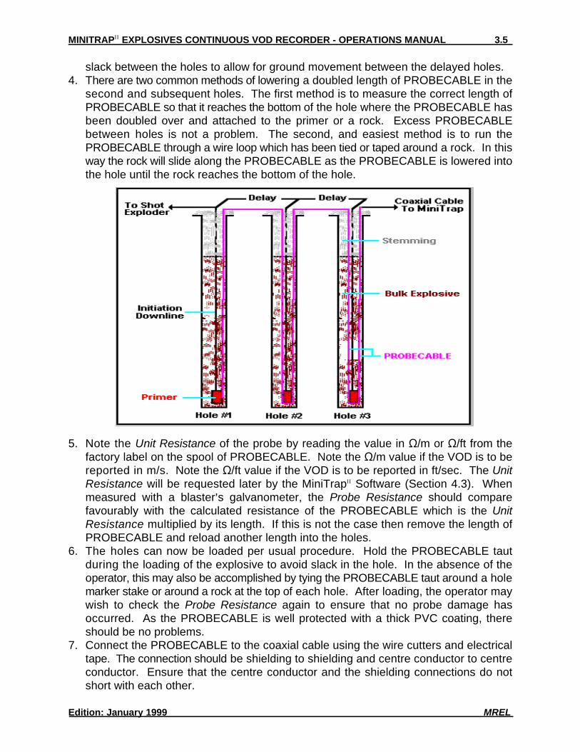
MULTIPLE HOLE RECORDINGS MAY BE PERFORMED AS FOLLOWS:1. Prepare the end of the PROBECABLE by using the wire cutters to remove the
insulation from the end and then short the wire by connecting the shielding wire to thecentre conductor wire and twisting them together. Protect the connection with electricaltape.
2. Using tape or wire, attach this finished end of the PROBECABLE to the primer or to arock and lower the PROBECABLE into the hole that is anticipated will detonate first ofall the series of holes to be recorded by the MiniTrap . Detonation cord downlines mayII
damage the PROBECABLE or cause side initiation of the bulk explosive. Wheninitiating with detonation cord, attach the PROBECABLE to a rock and lower it on theside of the hole opposite to the detonation cord downline.
3. Run the PROBECABLE between the first hole and the second hole leaving sufficient
slack between the holes to allow for ground movement between the delayed holes.4. There are two common methods of lowering a doubled length of PROBECABLE in the
second and subsequent holes. The first method is to measure the correct length ofPROBECABLE so that it reaches the bottom of the hole where the PROBECABLE hasbeen doubled over and attached to the primer or a rock. Excess PROBECABLEbetween holes is not a problem. The second, and easiest method is to run thePROBECABLE through a wire loop which has been tied or taped around a rock. In thisway the rock will slide along the PROBECABLE as the PROBECABLE is lowered intothe hole until the rock reaches the bottom of the hole.
5. Note the Unit Resistance of the probe by reading the value in S/m or S/ft from thefactory label on the spool of PROBECABLE. Note the S/m value if the VOD is to bereported in m/s. Note the S/ft value if the VOD is to be reported in ft/sec. The UnitResistance will be requested later by the MiniTrap Software (Section 4.3). WhenII
measured with a blaster=s galvanometer, the Probe Resistance should comparefavourably with the calculated resistance of the PROBECABLE which is the UnitResistance multiplied by its length. If this is not the case then remove the length ofPROBECABLE and reload another length into the holes.
6. The holes can now be loaded per usual procedure. Hold the PROBECABLE tautduring the loading of the explosive to avoid slack in the hole. In the absence of theoperator, this may also be accomplished by tying the PROBECABLE taut around a holemarker stake or around a rock at the top of each hole. After loading, the operator maywish to check the Probe Resistance again to ensure that no probe damage hasoccurred. As the PROBECABLE is well protected with a thick PVC coating, thereshould be no problems.
7. Connect the PROBECABLE to the coaxial cable using the wire cutters and electricaltape. The connection should be shielding to shielding and centre conductor to centreconductor. Ensure that the centre conductor and the shielding connections do notshort with each other.
8. At the MiniTrap , connect the coaxial cable to the PROBE connector on the outside ofII
the MiniTrap .II
9. The probe setup aspects of the test are complete. The MiniTrap can now be set upII
to record the test (Section 3.5).
3.4 PROBECABLE AND COAXIAL CABLE PROTECTION
It is important to protect the PROBECABLE and the coaxial cable from damage caused by:personnel and machinery operating on the blast; detonation of other holes and/or surfaceaccessories such as detonating cord, detonating relays, and shock tube bunch blocks.
The cables may be protected in many ways but experience has shown that it is best to leadthe PROBECABLE and coaxial cable under the detonating cord and leave a barrier ofsand or drill cuttings between them where they cross. A danger point is the collar area ofthe holes as the detonating cord or shock tube bunch blocks that initiate the downlinesmay cross directly over the PROBECABLE or coaxial cable. A good procedure is toprotect the area where there is a cross over for about 1.5 m (5 ft) along the length of cable.Experience has shown that a sand barrier thickness of 15-30 cm (0.5-1 ft) suffices toprotect the cables.
Having completed the probe setup procedure detailed in Sections 3.2 & 3.3, the operatorcan now prepare the MiniTrap to record the test using the following procedure:II
1. Ensure that the coaxial cable is connected to the MiniTrap signal input connectorII
labelled PROBE on the outside of the MiniTrap .II
2. Turn the MiniTrap power ON. The red STATUS indicator will illuminate. If theII
STATUS indicator flashes slowly, there is (old) VOD data in the MiniTrap =s memory.II
If you are sure that the old VOD data has been transferred to a computer and/or youwish to discard the old VOD data, press the NEXT TEST button to proceed. TheSTATUS indicator will illuminate and will stop flashing.
3. Look for red PROBE RESISTANCE OUT OF RANGE warning lights labelled AHIGH@and ALOW@. If there is an OUT OF RANGE warning light illuminated then there is aproblem with the probe or coaxial cable and refer immediately to Section 3.6. If thereis not a warning light illuminated then proceed to the next step.
4. Ensure that the TRIGGER switch is in the INT position. Use of the EXT position isdiscussed in Section 3.7.
5. Press the START button. The START indicator will illuminate. The MiniTrap is nowII
monitoring the blast to be fired and personnel may leave the MiniTrap unattended.II
When a sufficient probe length has been consumed by the blast (Section 3.8), theMiniTrap is triggered and will collect the VOD data. Upon triggering, the STARTII
indicator will flash indicating that the VOD data are being saved to the MiniTrap =s non-II
volatile memory. This takes approximately 2.5 minutes. When the data have beensaved, the START indicator will turn off and the STATUS indicator will flash slowly. Thedata are then ready to be transferred to a computer (Section 4.3).
6. Turn the MiniTrap power OFF.II
3.6 PROBE RESISTANCE OUT OF RANGE
There are two (2) PROBE RESISTANCE OUT OF RANGE warning indicators. One islabelled LOW, the other is labelled HIGH. The LOW indicator illuminates when the totalresistance of the probe plus the coaxial cable is less than 200 ohms. The HIGH indicatorilluminates when this total resistance is greater than 1,500 ohms. The MiniTrap is onlyII
calibrated to perform VOD tests between these two resistance values.
There can be several reasons why the total resistance may be LOW:1. A short circuit somewhere in the coaxial cable and probe assembly, including BNC
connector or BNC Adaptor.2. A damaged PROBEROD.3. An insufficient length of PROBECABLE connected in the test.
Items 1 and 2 above can be tested using a blaster=s galvanometer to test theresistance/continuity of the coaxial cable and probe assembly and solved by remaking theconnections and/or replacing the damaged PROBEROD. If item 3 is the cause thenreplace the BNC Adaptor used in the test with the supplied 200 ohm BNC Adaptor. The200 ohm BNC Adaptor provides an additional 200 ohms to the probe circuit and does notaffect the VOD results.
There can be several reasons why the total resistance may be HIGH:1. An open circuit somewhere in the coaxial cable and probe assembly, including BNC
connector or BNC Adaptor.2. A damaged PROBEROD.3. Too long a length of PROBECABLE connected in the test.
Items 1 and 2 immediately above can be tested using a blaster=s galvanometer to test theresistance/continuity of the coaxial cable and probe assembly and solved by remaking theconnections and/or replacing the damaged PROBEROD. If item 3 is the cause thenreduce the length of the PROBECABLE used in the test by cutting out excess
PROBECABLE between holes and remaking the connections using the wire cutters andelectrical tape or reducing the number of holes being recorded by cutting thePROBECABLE and remaking the appropriate connection with the wire cutters andelectrical tape.
3.7 UTILIZING THE EXTERNAL TRIGGER
In some VOD applications, it may be desirable to have the MiniTrap begin to recordII
exactly when a specific event occurs. For the specific event to start at time = 0 on theVOD graph, the EXT TRIG port on the outside of the MiniTrap is used.II
One of the BNC Adaptors supplied with the MiniTrap is connected to this port. Do notII
use the 200 ohm BNC Adaptor. A duplex wire is connected to the BNC Adaptor. Theother end of the duplex wire is prepared as follows: remove insulation from one of thewires and wrap it around the second, insulated, wire such that the circuit remains open.
Upon the duplex wire circuit becoming shorted, MiniTrap will begin recording data. AnyII
explosive event such as a detonator firing, detonating cord firing or a primer firing will shortsuch a circuit and cause the MiniTrap to collect data. Pre-trigger points will still beII
collected per the internal settings of the MiniTrap , but time=0 on the VOD graph will beII
the precise time when the circuit became shorted.
3.8 ADDITIONAL INFORMATION ON MEMORY AND TRIGGERING
This Section is provided for those operators interested in learning how the MiniTrap isII
able to automatically record the VOD information when the blast is fired. This knowledgeis not required to operate the MiniTrap but is provided for background interest only.II
MEMORY:
The MiniTrap has a circular memory of 1,048,576 data points. This memory is dividedII
into 262,144 pre-trigger data points and 786,432 post-trigger data points. The recordingspeed of the MiniTrap is 1MHz (1,000,000 data points per second). Therefore theII
MiniTrap has 262.144 ms of pre-trigger memory time and 786.432 ms of post-triggerII
By pressing the START button (Section 3.5) the MiniTrap begins recording VODII
information into all of the circular memory at a rate of 1MHz. It continues to recordinformation to the memory (overwriting data previously written to the memory in theprevious 1.048576 seconds) until a trigger signal is received.
TRIGGERING:
When utilizing the EXT TRIG trigger wire, the trigger signal that the MiniTrap receives isII
from the trigger wire being shorted by the explosives. This is time = 0 on the resultingVOD graph.
When not using the EXT TRIG (ie: using the INT TRIGGER setting), the MiniTrap isII
triggered by the signal received from the probe in the explosives as follows: When theexplosive detonates, the probe is consumed and the probe length is reduced. Thisreduces the resistance and thus the voltage decreases across the probe from the initial4.95 VDC value set automatically by the MiniTrap . When the voltage across the probeII
is reduced to approximately 4.5 VDC, the MiniTrap is Atriggered@. This is time = 0 on theII
resulting VOD graph.
Having received the trigger signal, the MiniTrap stores the 262.144 ms of VODII
information received immediately prior to the trigger signal into the pre-trigger memory.It also records 786.432 ms of VOD information after the trigger signal is received into thepost-trigger memory.
The graph on the following page shows the amount of PROBECABLE that must beconsumed for the MiniTrap to receive the trigger signal, given the Probe Resistance of theII
test. Two lines are shown, one for PROBECABLE (R/L = 11.5 S/m, 3.5 S/ft) and one forPROBECABLE-LR (R/L = 3.31 S/m, 1.01 S/ft). PROBECABLE-LR should be used fortests involving several holes where if PROBECABLE was used it would result in the TotalResistance exceeding 1500 S.
Notice on the graph that if a large resistance (such as 1300 S) is used in a test then50 metres of PROBECABLE (or approximately 175 metres of PROBECABLE-LR) must beconsumed to trigger the MiniTrap to record. If the first hole does not consume a sufficientII
length of PROBECABLE to trigger the MiniTrap to record, then all of the VOD data for theII
first hole will be before time = 0. The Operator should ensure that a sufficient length ofPROBECABLE is consumed at least 262.144 ms after the first hole in the test begins todetonate. This will ensure that no data from the first hole are lost.
The MiniTrap Software for Windows has been provided on 3.5 inch computer disks. ThisII
software can be installed on any PC system with the following minimum specifications:1. 386 or higher processor.2. 8 Mb RAM.3. 12 Mb hard drive space. (Windows >95 - 30 Mb free).4. Windows 3.x or Windows >95. Windows NT is not supported at this time.
4.2 INSTALLATION
To install the MiniTrap Software, start Windows and insert the firstII
installation disk (Disk 1) in to the 3.5 inch drive (usually A:). Windowsusers should start File Manager, then choose File-Run from the menuand type A:\install. Windows >95 users should choose Start-Run, thentype A:\install. Follow the instructions on the screen. When theinstallation is complete, re-boot Windows. The MiniTrap icon will beII
visible. To start the MiniTrap Software, double click on the MiniTrapII II
icon.
4.3 RETRIEVING DATAWARNING: DO NOT PRESS THE NEXT TEST BUTTON OTHERWISE ALL VOD DATAWILL BE ERASED FROM THE MINITRAP =S INTERNAL MEMORY. The procedure toII
retrieve data from the MiniTrap to a computer is as follows:II
1. Connect the communications cable, supplied with the MiniTrap , between the LPT1II
(parallel printer port) on the computer and the LPT COM port on the face of theMiniTrap . Do not connect to a Apass through@ port such as on a ZIP drive or aII
Adongle@ - incorrect data will result. Connection to a printer switching box will not causea problem.
2. Turn the MiniTrap power ON.II
3. Start the MiniTrap Software by double clicking on the MiniTrap icon or Start-II II
Programs-MiniTrap .II
4. At the Main Menu click on the Retrieve Databutton or with the keyboard press Alt-R. Dataretrieval can be accomplished without the useof a computer mouse by pressing Atab@ tomove between data entry fields.
5. Choose a drive, directory and file name inwhich the MiniTrap data will be stored.II
Also add comments about the data so thatthe file can be easily recalled.
The directory defaults to C:\minitrp2\data.The file name defaults to the year, monthand test number for that month.
Comments default to the time and date ofdata retrieval from the MiniTrap . OtherII
MiniTrap files already stored in theII
directory are also displayed.
Clicking on the Compress Data tick boxturns the file compression on or off. WithCompress Data on, the retrieval from theMiniTrap takes longer for someII
computers but the file size is reducedconserving computer disk space andallowing the file to fit on a floppy disk.
New directories can be created from this window using the New Directory button.
When all information is entered, click on the Retrieve Data button. Otherwise click onthe Cancel button to return to the Main Menu.
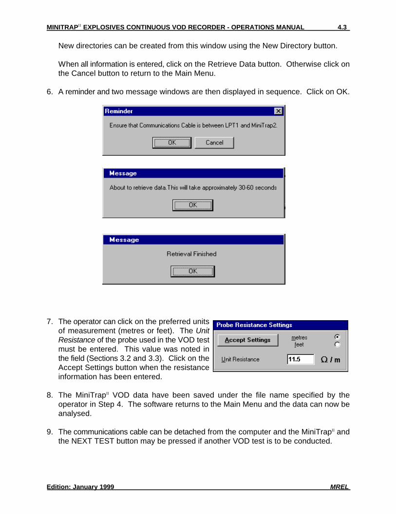
6. A reminder and two message windows are then displayed in sequence. Click on OK.
7. The operator can click on the preferred unitsof measurement (metres or feet). The UnitResistance of the probe used in the VOD testmust be entered. This value was noted inthe field (Sections 3.2 and 3.3). Click on theAccept Settings button when the resistanceinformation has been entered.
8. The MiniTrap VOD data have been saved under the file name specified by theII
operator in Step 4. The software returns to the Main Menu and the data can now beanalysed.
9. The communications cable can be detached from the computer and the MiniTrap andII
the NEXT TEST button may be pressed if another VOD test is to be conducted.
The procedure to select a MiniTrap file is as follows:II
1. From the Main Menu, click on the AnalyseVOD Data button or press Alt-A.
2. Click on the file name of interest, use the DataSet Comments box as a guide to each file=scontents.
Click on the Open button when a file has beenselected, otherwise click on the Cancel buttonto return to the Main Menu.
For this example X1 is chosen to illustrate theresults of a down-the-hole test on one hole.X1, X3, Z1, Z2 and Z3 are data files which haveall been included as examples with theMiniTrap Software.II
Chapter 5 provides the detailed procedures foranalysing the data in each of these files.
Clicking on the Open button automaticallystarts the MiniTrap VOD Analysis Software with the chosen data file. The followingII
section outlines the capabilities of the Analysis Software.
The following screen is displayed when a VOD file has been chosen for analysis:
The screen contains three main areas which are summarized below and discussed inmore detail in Chapter 5:Desktop: the area having the MREL logo as background. It is the area in which one ormore graphs can be displayed in maximized, normalized or minimized size states.Menu Bar: located across the top of the screen. It includes pull down menus for File,Graph, Edit, Analyse, Window and Help.Tools Bar: a moveable menu of icons which allows the operator to easily access analysisand graphics tools.
4.6 DESKTOP
When a data file is initially opened, the Desktop area of the software, which has as abackground the MREL logo, shows the Original Data graph in a normalized state. Forevery VOD file there is one Original Data graph collected during the VOD test. The dataand graphics on this Original Data graph can not be changed and is saved under thegraph name Original Data. New graph names must be given to the modified graphs (orsub-graphs). In this way the original data for the VOD test can never be lost. In theabove example, the X1 data file at this point in the analysis has only 1 graph, which is theOriginal Data graph.
From this original graph, other graphs, known as sub-graphs can be made and saved bythe operator under new graph names. These sub-graphs can include some or all of thedata in the original graph and can include graphics, text and analysis information as addedby the operator. The next time the data file is chosen for analysis, the original graph andall sub-graphs will be opened. There is no limit to the number of sub-graphs which can becreated from an original graph. Each sub-graph requires about 4K of disk memory. Theprocedure for creating sub-graphs is discussed in Chapter 5.
By clicking on either the normalize icon or on the maximize icon on any minimized graphs(per normal Windows procedures), the data can be viewed and analysed. In the examplebelow, the Original Data graph has been maximized. Items in the Tools Bar can now beused to analyse the data.
The Tools Bar contains a selection of twelve (12) tool buttons used to add ormodify the graph=s characteristics, text and graphics and to apply analysisprocedures to the data in the graphs to calculate VODs and delay timesbetween holes. The Tools Bar can be moved anywhere on the Desktop. Thebasic functions of each of the tool buttons are outlined below:
The Select Tool has many functions including:- selecting, moving, minimizing, maximizing and normalizing graphs;- selecting and modifying any component of the graphs by double
clicking on the component (ie: x-axis, y-axis, data, text, titles).
The Text Tool allows the operator to add new text/titles/comments tographs.
The Curve Tool allows the operator to add a curved line/pointer tographs.
The Line Tool allows the operator to add a straight line to graphs.
The Arrow Tool allows the operator to add a straight arrowed line/pointer to graphs.
The Box Tool allows the operator to add a box to graphs.
The Zoom In Tool allows the operator to zoom in on any part of the data and graph.
The Zoom Out Tool restores the data to the range before zooming in wasperformed.
The Position Tool displays the digital x, y (time, distance) position of any part of thegraph=s area.
The Data Value Tool displays the digital x, y (time, distance) value of any data pointon the graph.
The VOD Tool allows the operator to automatically calculate the VOD for any partof the graph by linear regression on all of the data between any two points on thegraph.
The Delay Tool allows the operator to automatically calculate the delay timebetween any two data points on the graph.
The Menu Bar contains a selection of six (6) pull down menus used to open data files andtheir associated graphs, save sub-graphs, print graphs, export data and graphics, move
and erase bad data points, arrange graphs on the Desktop and provide access to theonline Help. The Menu Bar is always located at the top of the Desktop. The basicfunctions of each of the pull down menus are outlined below:
The File menu allows the operator to Opendata files, display the name of the Current datafile, Save the current data file including theassociated graphs and Exit the Analysis sectionof the software.
The Graph menu allows the operator to List thegraphs associated with the current data file,Save and Rename the sub-graphs, Close thesub-graphs for the current analysis session,Delete the sub-graphs, Setup the printer,Preview how the graph will appear whenprinted, and Print the graph.
The Edit menu, shown below, allows the operator to Copy the Graph to the computer=smemory for pasting into other Windows applications such as word-processors, Copy theData, which comprises the graph, for subsequent pasting into Windows spreadsheets, andExport the data to an ASCII file for use by other graphics/analysis software.
The Analyse menu allows the operator toZoom in on the graph, Reset the graph tofull range, Undo the last Zoom, Move a baddata point, Remove bad data points,calculate a VOD using a linear regression,calculate a VOD from 2 Points on thegraph, and calculate a Delay. The Removeand Move menu items can be used on datapoints that sometimes result from inefficientshorting of the probe, causing downwardspikes in the data.Note that these menu items, except forRemove, Move, and VOD from 2 Pointsare also available on the Tools Bar.
When explosives react very slowly, there may be inefficient shorting of the probe. Thismay result in a graph similar to that shown below. The trend of the VOD is apparent,however there are many downward spikes on the trace which make the normalCalculating VOD using the regression inaccurate. In such cases the operator shouldCalculate VOD from 2 Points from the Analyse menu.
The Window menu allows the operator to automatically arrange the non-minimized graphson the Desktop in three (3) ways: Cascade, tile Vertically, and tile Horizontally. Thismenu also allows the operator to automatically Arrange the minimized graph icons.
The Help menu provides the operator with instructions on How to use the online helpmanual, provides the operator access to the online help manual through the Contents ofthe manual and displays information About the MiniTrap Software including contactII
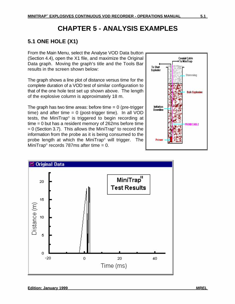
From the Main Menu, select the Analyse VOD Data button(Section 4.4), open the X1 file, and maximize the OriginalData graph. Moving the graph=s title and the Tools Barresults in the screen shown below:
The graph shows a line plot of distance versus time for thecomplete duration of a VOD test of similar configuration tothat of the one hole test set up shown above. The lengthof the explosive column is approximately 18 m.
The graph has two time areas: before time = 0 (pre-triggertime) and after time = 0 (post-trigger time). In all VODtests, the MiniTrap is triggered to begin recording atII
time = 0 but has a resident memory of 262ms before time= 0 (Section 3.7). This allows the MiniTrap to record theII
information from the probe as it is being consumed to theprobe length at which the MiniTrap will trigger. TheII
Since only one hole was tested, and the time for the explosive to detonate (approximately5ms) is far less than the 1,049ms that the MiniTrap records, a large amount of extra dataII
was recorded after the detonation in the hole was complete. Using the Zoom In Tool(Section 4.7), the operator can focus on the area of interest: the part of the graph thatshows the explosive detonating.
The following screen shows results from zooming in on the data of interest. If the wrongarea is chosen, use the Zoom Out Tool to undo the Zoom In. On the graph, for interestonly, the Data Value Tool has been used to click on the graph to find the distance atwhich time = 0. The x, y (time, distance) coordinates of this point are shown just under theMenu Bar.
To change the format of the Distance and Time axes, use the Select Tool to double clickon them. Double clicking with this tool on the axis labels, axis titles, graph title box andon the data allows the operator to change the attributes of these items. The Text Tool canbe used to add additional comments on the graph.
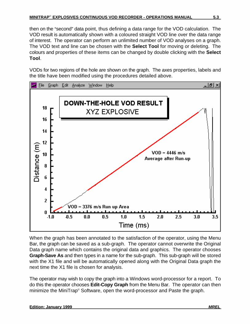
To analyse the data for VODs, choose the VOD Tool. The software calculates the VODby conducting a linear regression on the data contained between two data points chosenby the operator. The software prompts the operator to click on the Afirst@ data point and
then on the Asecond@ data point, thus defining a data range for the VOD calculation. TheVOD result is automatically shown with a coloured straight VOD line over the data rangeof interest. The operator can perform an unlimited number of VOD analyses on a graph.The VOD text and line can be chosen with the Select Tool for moving or deleting. Thecolours and properties of these items can be changed by double clicking with the SelectTool.
VODs for two regions of the hole are shown on the graph. The axes properties, labels andthe title have been modified using the procedures detailed above.
When the graph has been annotated to the satisfaction of the operator, using the MenuBar, the graph can be saved as a sub-graph. The operator cannot overwrite the OriginalData graph name which contains the original data and graphics. The operator choosesGraph-Save As and then types in a name for the sub-graph. This sub-graph will be storedwith the X1 file and will be automatically opened along with the Original Data graph thenext time the X1 file is chosen for analysis.
The operator may wish to copy the graph into a Windows word-processor for a report. Todo this the operator chooses Edit-Copy Graph from the Menu Bar. The operator can thenminimize the MiniTrap Software, open the word-processor and Paste the graph.II
To print directly from the MiniTrap Software, the operator must select the printer andII
paper by choosing Graph-Print Setup from the Menu Bar. It is useful to activate a printpreview mode to ensure that all of the graph components fit on the paper in the correctposition. To start the preview mode, the operator chooses Graph-Print Preview from theMenu Bar. Graph elements can be moved and modified in this mode until they are correctfor printing. The operator then chooses Graph-Print from the Menu Bar to print the graph.To exit the print preview mode, the operator chooses Graph-End Print Preview from theMenu Bar.
The operator is encouraged to experiment with analysing, formatting and printing the dataand graphs contained in the X1 file. No matter what changes are made to the data in thesub-graphs, the Original Data graph cannot be changed and will always be available forsubsequent analysis.
5.2 THREE HOLES (X3)
From the Main Menu, select the Analyse VOD Data button (Section 4.4) or, if continuingfrom the previous example (Section 5.1), choose File-Open and open the X3 file.Maximize the Original Data graph. Moving the graph=s title and the Tools Bar results inthe screen shown.
The graph shows a line plot of distance versus time for the complete duration of a VODtest. The test was of similar configuration to that of the three hole test shown on the nextpage.
Three 10m deep holes were monitored. Each hole contained a column of approximately5m of explosives and the blast was tied in with a 17ms delay between holes.
Notice on the diagram that the PROBECABLE in Hole 1 was not terminated at the primerbut was run down and out of the hole in a method similar to Holes 2 and 3. In this way, thedetonation of the primer in Hole 1 immediately cuts off or shortens the PROBECABLE by10m thereby assuring that the MiniTrap will be triggered to record (time = 0) upon theII
primer in Hole 1 firing. This is evident on the graph. Also notice that if Hole 2 fired beforeHole 1 then approximately 35m of PROBECABLE (comprised of 20m in Hole 1 + 5mspacing between holes + 10m in Hole 2) would have been cut off. Of course in that caseno data would have been recorded for Hole 1, only for Holes 2 and 3.
The data can be analysed to determine the actual delays between holes and the VODs ofthe explosives in each of the holes.
To determine the delays between holes, choose the Delay Tool (Section 4.6). Thesoftware calculates the delay time by measuring the difference in time between two datapoints chosen by the operator. The software prompts the operator to click on the Afirst@data point and then on the Asecond@ data point, thus defining a data range for the delaycalculation. The delay result is automatically shown with a coloured straight delay lineover the data range of interest. The operator can perform an unlimited number of delayanalyses on a graph. The delay text and line can be chosen with the Select Tool formoving or deleting. The colours and properties of these items can be changed by double
Delay times between Holes 1 and 2, and 2 and 3 are shown on the graph. The axesproperties, labels and the title have been modified using the procedure detailed inSection 5.1.
When the graph has been annotated to the satisfaction of the operator, using the MenuBar, the new graph can be saved as a sub-graph and printed per the procedures inSection 5.1.
The operator can zoom in on each of the three holes to calculate the VODs in each holeper the procedures in Section 5.1 and save the zoomed VOD results for each hole as sub-graphs as illustrated below:
The operator is encouraged to experiment with analysing, formatting and printing the dataand graphs contained in the X3 file. No matter what changes are made to the data in thesub-graphs, the Original Data graph cannot be changed and will always be available forsubsequent analyses.
As detailed in Section 3.2, a typical VOD test of an explosives sample is shown below.
From the Main Menu, select the Analyse VOD Data button (Section 4.4) or, if continuingfrom the previous example (Section 5.2), choose File-Open and open the Z2 file. Thefigure below shows the result of zooming on the Original Data graph, conducting a VODanalysis, and performing some graphics editing.
This result is typical for an unconfined explosive failing to detonate completely.
The figure on the right is the result ofanalysing and editing the Original Datagraph of the Z3 file.
This result illustrates the effect of confiningthe explosive in Schedule 40 steel pipe (astandard substitute for rock). The explosivedetonates fully when loaded in steel pipe butfails when unconfined as shown in theprevious graph.
The Z1 file contains a sub-graph which is an extreme illustration of the MiniTrap =s abilityII
to record changes in VOD along the length of an explosive column. It is the result of aVOD test on unconfined bulk explosive. It can be observed that a second primer wasplaced in the explosive column which had not been tied into the shot exploder. As can beseen, the operator can determine the VOD anywhere along the 0.8 m long unconfinedsample.
The operator is encouraged to experiment with analysing, formatting and printing the dataand graphs contained in the Z1 file. No matter what changes are made to the data in thesub-graphs, the Original Data graph cannot be changed and will always be available forsubsequent analyses.
It is straightforward to send a MiniTrap file for analysis/review by another operator whoII
also has the MiniTrap Software.II
When a file is saved on a computer, the file name takes the form of filename.filetype,otherwise known as root.extension. When a MiniTrap file is saved using a name chosenII
by the operator (for example: test), several files with different filetypes are automaticallycreated by the MiniTrap Software all with the same filename, test.II
To email a MiniTrap file of test, attach all the MiniTrap files with the same filename to theII II
email.
For example:test.mt2 (the MiniTrap settings file, which is a readable text file)II
test.raw (the MiniTrap data file if the data were not compressed)II
test.cmp (the MiniTrap data file if the data were compressed)II
test.e1, test.e2 etc... (the series of sub-graph files the operator saved during VOD analysis)
test.r1, test.r2 etc... (the data points removed from a sub-graph by the operator)test.m1, test.m2 etc... (the data points moved in a sub-graph by the operator)
As part of MREL=s ongoing commitment to Customer Satisfaction, MREL VOD Specialistswill be pleased to review your analysis of your VOD data. If you would like to have aAsecond opinion@ from MREL on your analysis of a specific test, send an email [email protected] with a brief description of the test and attach all of the files.