TM 5-5430-210-12 TECHNICAL MANUAL OPERATOR AND ORGANIZATIONAL MAINTENANCE MANUAL TANK, FABRIC, COLLAPSIBLE, POL, 3,000 Gallon (11 355 Liter) NSN 5430-00-268-8187 10,000 Gallon (37,850 Liter) NSN 5430-00-052-3412 10,000 Gallon (37,850 Liter) NSN 5430-00-641-8552 50,000 Gallon (189 250 Liter) NSN 5430-00-182-8181 This copy is a reprint which includes current pages from Changes 1 through 11. HEADQUARTERS, DEPARTMENT OF THE ARMY 30 NOVEMBER 1978
Transcript
TM 5-5430-210-12
TECHNICAL MANUAL
OPERATOR AND ORGANIZATIONALMAINTENANCE MANUAL
TANK, FABRIC,COLLAPSIBLE, POL,
3,000 Gallon (11 355 Liter)NSN 5430-00-268-8187
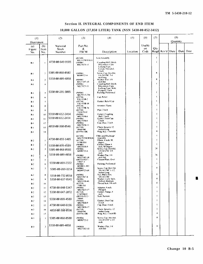
10,000 Gallon (37,850 Liter)NSN 5430-00-052-3412
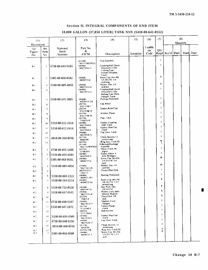
10,000 Gallon (37,850 Liter)NSN 5430-00-641-8552
50,000 Gallon (189 250 Liter)NSN 5430-00-182-8181
This copy is a reprint which includes currentpages from Changes 1 through 11.
HEADQUARTERS, DEPARTMENT OF THE ARMY30 NOVEMBER 1978
TM 5-5430-210-12
WARNING
FLAMMABLE FUEL
Death
or serious injury may result if personnel fail to strictlyobserve safety precautions. Do not allow any smokingwithin 100 feet (30.50 meters) of the storage area. Avoidspillage of fuel. When spillage occurs, cover the affectedarea with dry soil to reduce its rate of vaporization. Posi-tion fire extinguishers at readily accessible positionsaround the tank(s).
Avoid getting fuel on the body or clothing. If clothing be-comes saturated, remove the clothing immediately andwash the body thoroughly with hot, soapy water.
Safety berms must have capacities of not less than oneand one half (1 1/2) times that of their tank capacities.Drycleaning solvent, P-D-680, used to clean parts is po-tentially dangerous to personnel and property. Avoid re-peated and prolonged skin contact. Do not use near openflame or excessive heat. Flash point of solvent is 100 de-grees F -138 degrees F (38 degrees C - 59 degrees C).
TM 5-5430-210-12C 11
CHANGE
NO. 11
HEADQUARTERSDEPARTMENT OF THE ARMY
WASHINGTON, D. C., 31 October 1994
Operator and Organizational Maintenance Manual
TANK FABRIC, COLLAPSIBLE, POL,3,000 GALLON (11,355 Liter)
NSN 5430-00-268-818710,000 Gallon (37,850 Liter)
NSN 5430-00-052-341210,000 Gallon (37,850 Liter)
NSN 5430-00-641-855220,000 GALLON (75,700 Liter)
NSN 5430-01-215-752550,000 Gallon (189,250 Liter)
NSN 5430-00-182-8181
DISTRIBUTION STATEMENT A: Approved for public release; distribution is unlimited
TM 5-5430-218-13,30 November 1978, is changed as follows:
1. Remove and insert pages as indicated below. New or changed text material is indicated by a vertical barin the margin. An illustration change is indicated by a miniature pointing hand.
Remove pages Insert pages
i and ii i and ii
1-1 and 1-2 1-1 and 1-2
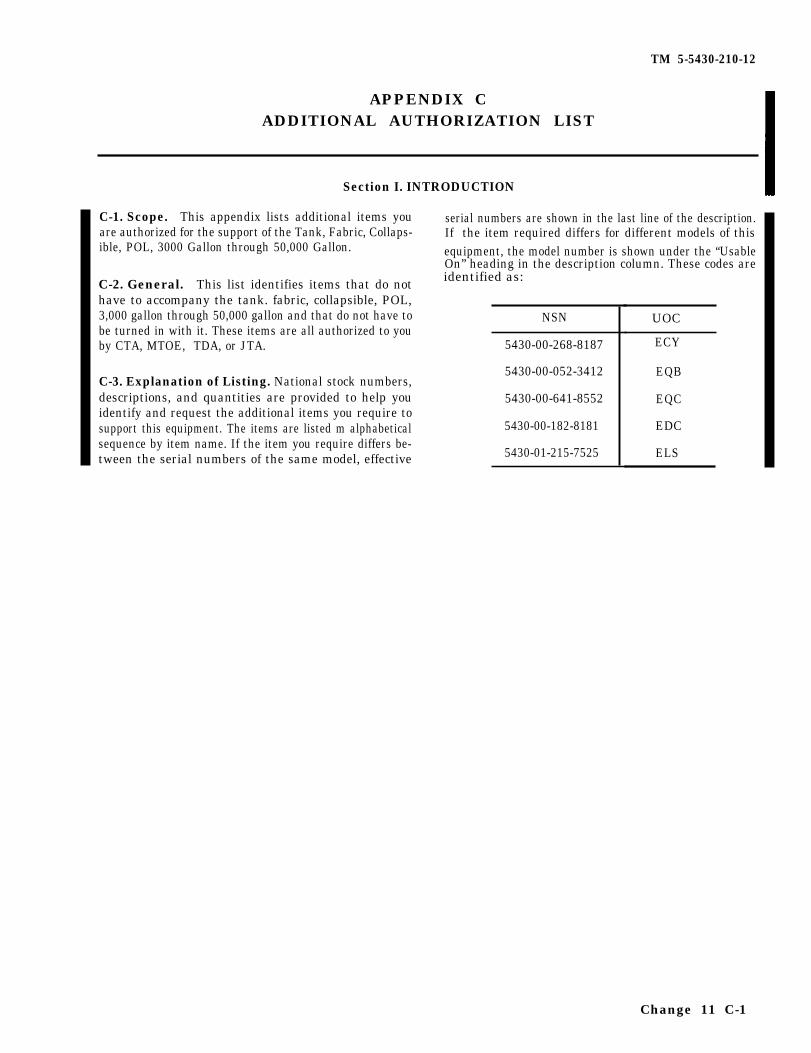
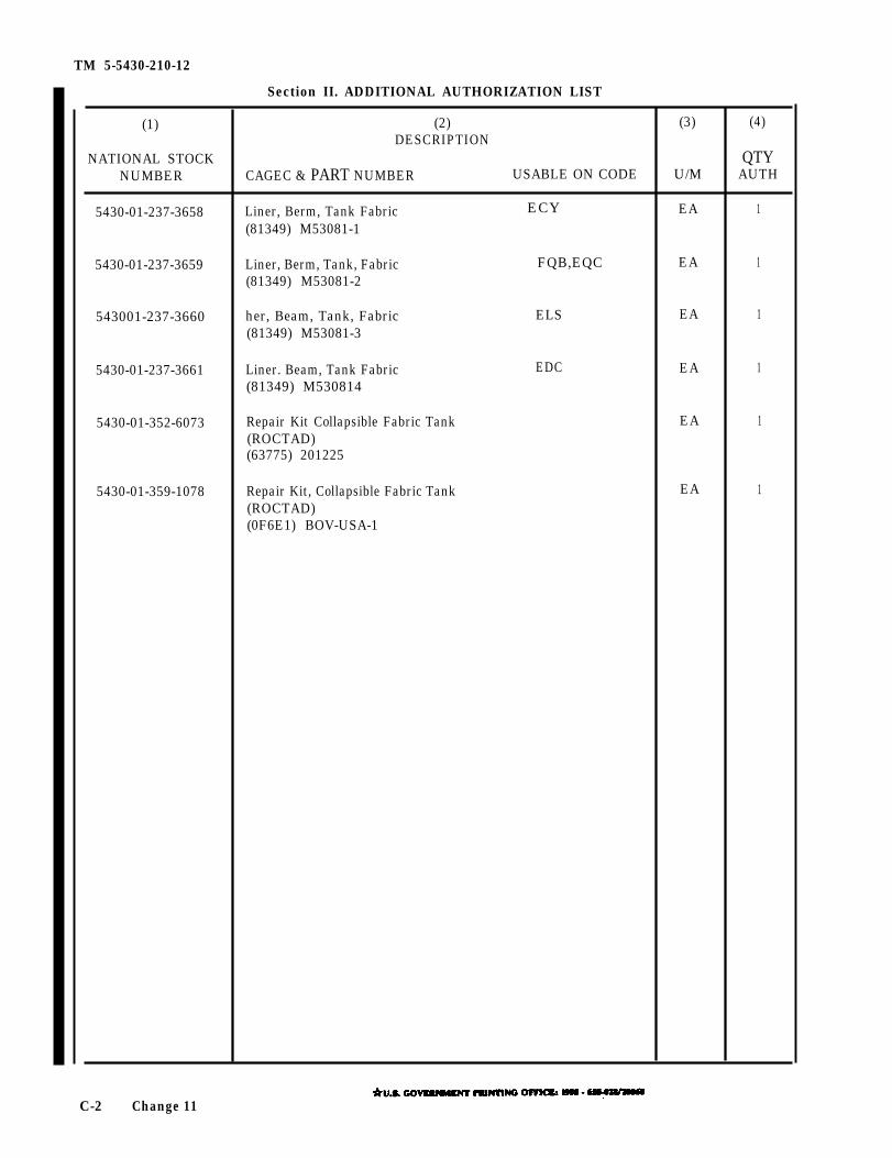
C-1/(C-2 blank) C-1 and C-2
2. Retain this sheet in front of manual for reference purposes.
TM 5-5430-210-12C 11
By Order of the Secretary of the Army:
Official:
Administrative Assistant to theSecretary of the Army
07709
GORDON R. SULLIVANGeneral , Uni ted States Army
Chief of Staff
DISTRIBUTION:To be distributed in accordance with DA Form 12-25-E, block no. 1735, requirements for
Approved for public release; Distribution is unlimited
TM 5-5430-210-12,30 November 1978 is changed as follows:
1. Remove and insert pages as indicated below. New or changed text material is indicated by a vertical bar inthe margin. An illustration change is indicated by a miniature pointing hand.
Remove pages Insert pages
B-1 and B-2 B-1 and B-2B-5 through B-10 B-5 through B-10
B-11 and B-12 B-11 and B-12
2. Retain this sheet in front of manual for reference purposes.
By Order of the Secretary of the Army:
MILTON H. HAMILTONAdministrative Assistant to the
Secretary of the Army02292
GORDON R. SULLIVANGeneral, United States Army
Chief of Staff
DISTRIBUTION:T o b e d i s t r i b u t e d i n a c c o r d a n c e w i t h D A F o r m 1 2 - 2 5 - E , b l o c k 1 7 3 5 ,
o p e r a t o r a n d U n i t M a i n t e n a n c e r e q u i r e m e n t s f o r T M 5 - 5 4 3 0 - 2 1 0 - 1 2 .
Approved for public release; distribution is unlimited
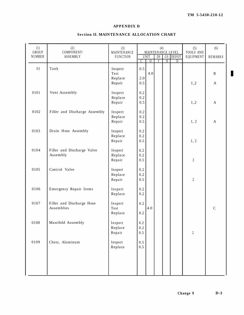
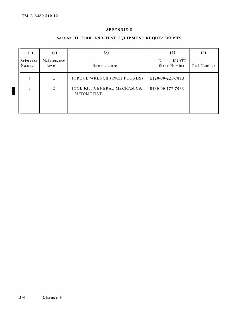
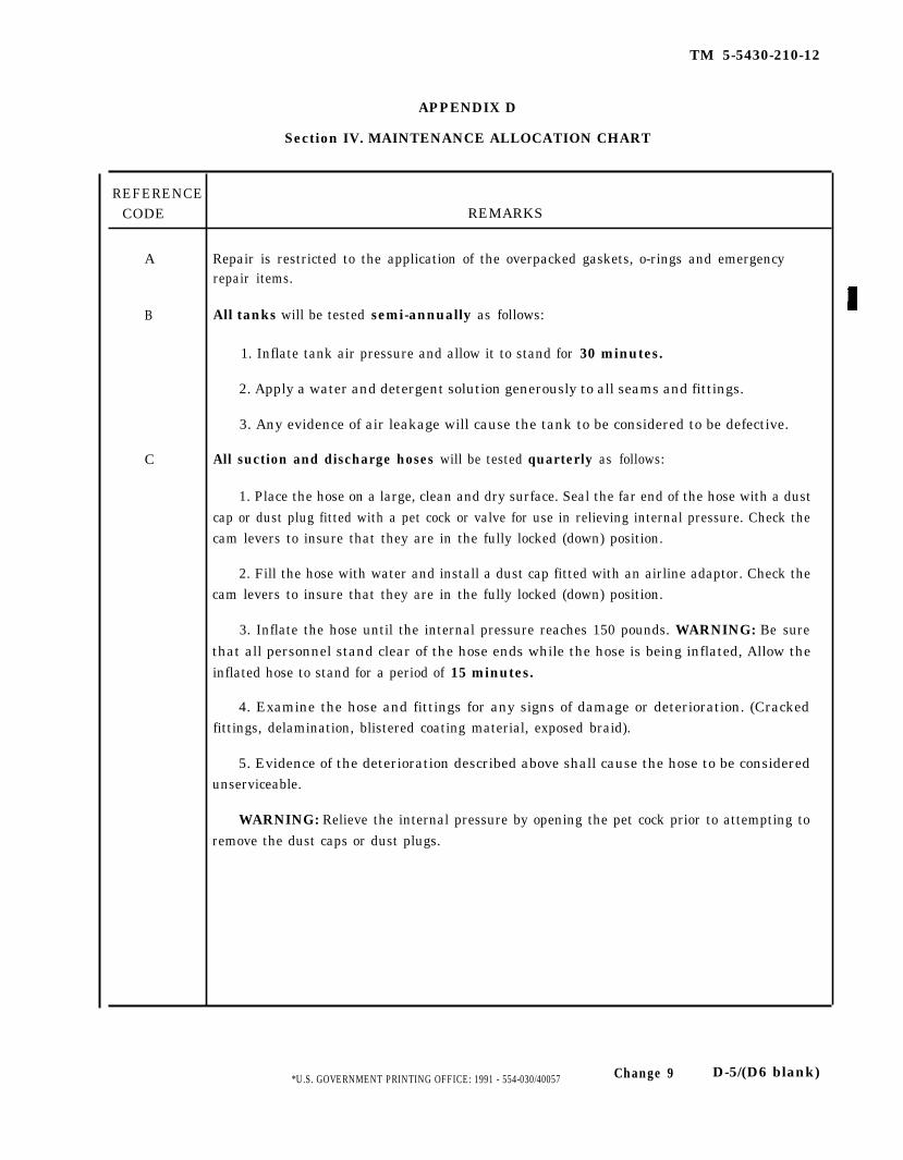
TM 5–5430-210-12, 30 November 1978, is changed as follows:
1. Remove and insert pages as indicated below. New or changed text material is indicated by a vertical bar inthe margin. An illustration change is indicated by a miniature pointing hand.
Remove pages Insert pages
D-3 through D-5/(D-6 blank) D-3 through D-5/(D-6 blank)
2. Retain this sheet in front of manual for reference purposes.
By Order of the Secretary of the Army:
CARL E. VUONOGeneral, United States Army
Chief of Staff
Official:THOMAS F. SIKORABrigadier General, United States Army
The Adjutant General
DISTRIBUTION:To be distributed in accordance with DA Form 12-25E, (qty rqr block no. 1735)
Approved for public release; distribution is unlimited
TM 5–5430–210–12, 30 November 1978 is changed as follows:
1. Remove and insert pages as indicated below. New or changed text material is indicated by avertical bar in the margin. An illustration change is indicated by a miniature pointing hand.
Remove pages Insert pages
2-17 and 2–18 2–17 and 2–18- - - - 2-18 .1/(2–18.2 blank)
2. Retain this sheet in front of manual for reference purposes.
By Order of the Secretary of the Army:
CARL E. VUONOGeneral, United States Army
Chief of Staff
Official:PATRICIA P. HICKERSONColonel, United States Army
The Adjutant General
DISTRIBUTION:To be distributed in accordance with DA Form 12-25E, (qty rqr block no. 1735).
C 8
TM 5-5430-210-12C7
CHANGE HEADQUARTERSDEPARTMENT OF THE ARMY
NO. 7 WASHINGTON, D.C., 17 March 1989
Operator and Organizational Maintenance Manual
TANK, FABRIC, COLLAPSIBLE, POL,3 ,000 Ga l lon (11 ,355 L i te r )
NSN 5430-00-268-818710,000 Ga l lon (37 ,850 L i te r )
NSN 5430-00-052-341210,000 Ga l lon (37 ,850 L i te r )
NSN 5430-00-641-855220,000 Ga l lon (75 ,700 L i te r )
NSN 5430-01-215-752550,000 Ga l lon (189 ,250 L i te r )
NSN 5430-00-182-8181
TM 5-5430-210-12, 30 November 1978, is changed as follows:
1. Remove and insert pages as indicated below. New or changed text mater ia li s i nd ica ted by a ve r t i ca l ba r in the marg in . A n i l l u s t r a t i o n c h a n g e i s i n d i c a t e dby a miniature point ing hand.
Remove pages Insert pages
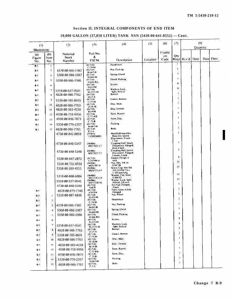
B-5 through B-10 B-5 through B-10
2. Reta in th i s shee t in f ron t o f manua l fo r re fe rence purposes .
By Order of the Secretary of the Army:
C.ARLE. VUONOGeneral, United States Army
Chief of SraffOfflcial:
WILLIAM J. MEEHAN, IIIBrigadier General, United States Army
The Adjutant General
DISTRIBUTION:To be distr ibuted in accordance with DA Form 12-25A, Operator and Unit Mainte-
nance Requirements for Tank, Fabr ic, Col lapsible, POL, 50,000, 10,000, 3,000 GAL.
TM 5-5430-210-12C 6
CHANGE
No. 6
HEADQUARTERSDEPARTMENT OF THE ARMY
WASHINGTON, D.C., 17 June 1988
Operator and Organizat ional Maintenance Manual
TANK, FABRIC, COLLAPSIBLE, POL,3 ,000 Ga l lon (11 ,355 L i te r )
NSN 5430-00-268-818710,000 Ga l lon (37 ,850 L i te r )
NSN 5430-00-052-341210,000 Ga l lon (37 ,850 L i te r )
NSN 5430-00-641-855220,000 Ga l lon (75 ,700 L i te r )
NSN 5430-01-215-752550,000 Ga l lon (189 ,250 L i te r )
NSN 5430-00-182-8181
TM 5-5430-210-12, 30 November 1978, is changed as follows:
1. Remove and insert pages as indicated below. New or changed test mater ia li s i nd ica ted by a ve r t i ca l ba r in the marg in . A n i l l u s t r a t i o n c h a n g e i s i n d i c a t e dby a miniature point ing hand.
Remove pages Insert Pages
1-1 and 1-2 1-1 and 1-22-17 and 2-18 2-17 and 2-18
2. Reta in th i s shee t in f ron t o f manua l fo r re fe rence purposes .
By Order of the Secretary of the Army:
CARLE. VUONOGeneral, United States Army
ChiefofStaff
Official:
R. L. DILWORTHBrigadier General, United States Amy
The Adjutant General
DISTRIBUTION:To be distr ibuted in accordance with DA Form 12-25A, Operator and Unit Mainte-
nance Requirements for Tank, Fabr ic, Col lapsible, POL, 50,000, 10,000, 3,000 GAL.
TM 5-5430-210-12C 5
CHANGE
NO. 5
HEADQUARTERSDEPARTMENT OF THE ARMY
WASHINGTON, D.C., 24 Apri l 1987
Operator and Organizat ional Maintenance Manual
TANK, FABRIC, COLLAPSIBLE, POL,3 ,000 Ga l lon (11 ,355 L i te r )
NSN 5430-00-268-818710,000 Ga l lon (37 ,850 L i te r )
NSN 5430-00-052-341210,000 Ga l lon (37 ,850 L i te r )
NSN 5430-00-641-855220,000 Ga l lon (75 ,700 L i te r )
NSN 5430-01-215-752550,000 Ga l lon (189 ,250 L i te r )
NSN 5430-00-182-8181
TM 5-5430-210-12, 30 November 1978, is changed as follows:
1. Title is changed as shown above.
2. Remove and insert pages as indicated below. New or changed text mater ia li s i nd ica ted by a ve r t i ca l ba r in the marg in . A n i l l u s t r a t i o n c h a n g e i s i n d i c a t e dby a miniature point ing hand.
Remove pages Insert pages
a / bi and ii1 -1 th rough 1 -2 .1 /1 -2 .21-3 th rough 1 -5 /1 -6
- - - - -2-3 and 2-42-7 through 2-12
- - - - -
2-15 through 2-18B - 9 / B - l oB-15 and B-16Index 1 through Index 3/Index 4
a / bi and ii1 -1 th rough 1 -2 .1 /1 -2 .21-3 th rough 1 -5 /1 -62-2. 1/2-2. 22-3 and 2-42-7 through 2-122-14. 1/2-14. 22-15 through 2-18B-9 through B-10.2B-15 and B-16Index 1 through Index 3/Index 4
3. Reta in th i s shee t in f ron t o f manua l fo r re fe rence purposes .
TM 5-5430-210-12C 5
By Order of the Secretary of the Army:
Official:
R. L. DILWORTHBrigadier General, United States Army
The Adjutant General
JOHN A. WICKHAM, JR.General, United States Army
Chief of Staff
DISTRIBUTION :To be distributed in accordance with DA Form 12-25A, Operator and Unit Maintenance
Requirements for Tank, Fabric, Col lapsible, POL, 50,000, 10,000 3,000 GAL
CHANGE
No. 4
TM 5-5430-210-12C 4
HEADQUARTERSDEPARTMENT OF THE ARMY
WASHINGTON, D.C., 15 October 1986
Operator and Organizat ional Maintenance
TANK, FABRIC, COLLAPSIBLE, POL,3 ,000 Ga l lon (11 ,355 L i te r )
NSN 5430-00-268-818710,000 Ga l lon (37 ,850 L i te r )
NSN 5430-00-052-341210,000 Ga l lon (37 ,850 L i te r )
NSN 5430-00-641-855250,000 Ga l lon (189 ,250 L i te r )
NSN 5430-00-182-8181
Manual
TM 5-5430-210-12, 30 November 1978, is changed as follows:
1. Remove and insert pages as indicated below. New or changed text mater ia li s i nd ica ted by a ve r t i ca l ba r in the marg in . A n i l l u s t r a t i o n c h a n g e i s i n d i c a t e dby a miniature point ing hand.
Remove pages Insert pages
1-1 through 1-4 1-1 through 1-4B-7 and B-8 B-7 and B-8D-3 and D-4 D-3 and D-4
2. Reta in th i s shee t in f ron t o f manua l fo r re fe rence purposes .
By Order of the secretary of the Army:
JOHN A. WICKHAM, JR.GenemLUnited Statea Arrny
Official: Chief of Staff
R.L.DILWORTHBrigadier General, United States Army
The Adjutant General
DISTRIBUTION:To be distr ibuted in accordance wi th DA Form 12-25A, Operator and Organizat ional
Maintenance Requirements for Tank, Fabr ic, Col lapsible, POL, 50,000, 10,000,3,000 GAL (TM 5-5430-210-12)
TM 5-5430-210-12C 3
C H A N G E
NO. 3
1.
HEADQUARTERSDEPARTMENT OF THE ARMY
WASHINGTON, D. C., 24 June 1983
O P E R A T O R A N D O R G A N I Z A T I O N A L M A I N T E N A N C E M A N U A LTANK, FABRIC, COLLAPSIBLE, POL,
3,000 Gallon (11,355 Liter)NSN 5430-00-268-8187
10,000 Gallon (37,850 Liter)NSN 5430-00-052-3412
10,000 Gallon (37,850 Liter)NSN 5430-00-641-8552
50,000 Gallon (189,250 Liter)NSN 5430-00-182-8181
TM 5-5430-210-12, 30 November 1978, is changed as follows:
Remove and insert pages as indicated below:
Remove pages Insert pages
Appendix B B-1 thru B-14 B-1 thru B-14
2. New or changed text material is indicated by a vertical bar in the margin. An illustration changeis indicated by a miniature pointing hand.
3. Retain this sheet in front of manual for references purposes.
By Order of the Secretary of the Army:
E. C. MEYERGeneral, United States Army
Chief of Staff
Official:
ROBERT M. JOYCEMajor General, United States Army
The Adjutant General
DISTRIBUTION:To be distributed in accordance with DA Form 12-25A, Operator Maintenance Requirements for
Petroleum Distribution.
TM 5-5430-210-12C2
CHANGE HEADQUARTERSDEPARTMENT OF THE ARMY
No. 2
1.
WarningTable of Contents i and ii i and iiChapter 1 1-3 and 1-4 1-3 and 14Chapter 2 2-3 and 2-4 2-3 and 2-4
2-9 and 2-10 2-9 and 2-102-17 and 2-18 2-17 thru 2-19/2-20
Chapter 3 3-1 and 3-2 3-1 and 3-2Appendix B B-5 thru B-10 B-5 thru B-10
WASHINGTON, D.C., 15 January 1982
OPERATOR AND ORGANIZATIONAL MAINTENANCE MANUALTANK, FABRIC, COLLAPSIBLE, POL,
3,000 Gallon (11,355 Liter)NSN 5430-00-268-8187
10,000 Gallon (37,850 Liter)NSN 54300-052-3412
10,000 Gallon (37,850 Liter)NSN 5430040-641-8552
50,000 Gallon (189,250 Liter)NSN 5430-00-182-8181
TM 5-5430-210-12,30 November 1978, is changed as follows:
Remove and insert pages as indicated below:
Remove pages Insert pages
a/b
2. New or changed text material is indicated by a vertical bar in the margin. An illustration changeis indicated by a miniature pointing hand.
3. Retain this sheet in front of manual for reference purposes.
By Order of the Secretary of the Army:
Official:
E. C. MEYERGeneral, United States Army
Chief of Staff
ROBERT M. JOYCEBrigadier General, United States Army
The Adjutant General
DISTRIBUTION:TO be distributed in accordance with DA Form 12-25A,0perator Maintenance Requirements for
Petroleum Distribution.
TM 5-5430-210-12C 1
CHANGE HEADQUARTERSDEPARTMENT OF THE ARMY
No. 1 WASHINGTON, DC., 25 April 1980
OPERATOR AND ORGANIZATIONAL MAINTENANCE MANUALTANK, FABRIC, COLLAPSIBLE, POL,
3,000 Gallon (11,355 Liter)NSN 5430-00-268-8187
10,000 Gallon (37,850 Liter)NSN 5430-00-052-3412
10,000 Gallon (37,850 Liter)NSN 5430-00-641-8552
50,000 Gallon (189,250 Liter)NSN 5430-00-182-8181
TM 5-5430-210-12, 30 November 1978, is changed as follows:
1 . Remove and insert pages as indicated below.
Remove pages Insert pages
Table of Contents i and ii i and iiChapter 1 1-1 thru 1-5/1-6 1-1 thru 1-5/1-6Chapter 2 2-9 thru 2-12 2-9 thur 2-12Chapter 3 3-1 and 3-2 3-1 and 3-2Appendix B B-5 thru B-10 B-5 thru B-10Appendix D D-3 and D-4 D-3 thru D-5/D-6Appendix F F-1 /F-2 F-1 /F-2
2. New or changed text material is indicated by a vertical bar in the margin.An il lustration change is indicated by a miniature pointing hand.
3. Retain this sheet in front of manual for reference purposes.
By Order of the Secretary of the Army:
Official:
J. C. PENNINGTONMajor General United States Army
The Adjutant General
E. C. MEYERGeneral United States Army
Chief of Staff
DISTRIBUTION:To be distributed in accordance with DA Form 12-25A Operator Maintenance
Requirements for Petroleum Distribution.
TM 5-5430-210-12
WARNING
FLAMMABLE FUEL
Death
or serious injury may result if personnel fail to strictlyobserve safety precautions. Do not allow any smokingwithin 100 feet (30.50 meters) of the storage area. Avoidspillage of fuel. When spillage occurs, cover the affectedarea with dry soil to reduce its rate of vaporization. Posi-tion fire extinguishers at readily accessible positionsaround the tank(s).
Avoid getting fuel on the body or clothing. If clothing be-comes saturated, remove the clothing immediately andwash the body thoroughly with hot, soapy water.
Safety berms must have capacities of not less than oneand one half (1 1/2) times that of their tank capacities.Drycleaning solvent, P-D-680, used to clean parts is po-tentially dangerous to personnel and property. Avoid re-peated and prolonged skin contact. Do not use near openflame or excessive heat. Flash point of solvent is 100 de-grees F -138 degrees F (38 degrees C -59 degrees C).
Change 5 a/(b blank)
*TM 5-5430-210-12
TECHNICAL MANUAL HEADQURTERSDEPARTMENT OF THE ARMY
NO. 5-5430-21012 Washington, D.C., 30 November 1978
OPERATOR AND ORGANIZATIONAL MAINTENANCE MANUALTANK, FABRIC, COLLAPSIBLE, POL,
You can help improve this manual If you find any mistake or if you know of way to improve the procedures,please let us know. Mail your letter, DA Form 2028 (Recommended Changes to Publications and BlankForms), or DA Form 2028-2 located in the back of this manual direct to: Commander, U.S. Army Aviationand Troop Command, ATTN: AMSAT-I-MP, 4300 Goodfellow Boulevard, St. Louis, MO 631201798. Areply will be furnished directly to you.
DISTRIBUTION STATEMENT: Approved for public release; distribution is unlimited.
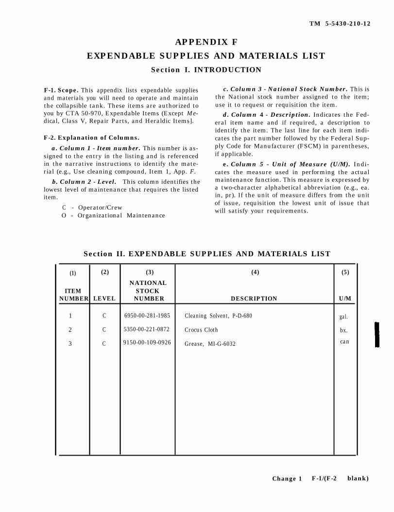
1-1. Scope. This manual covers the information andinstructions necessary for the operation and maintenanceof the 3,000-gallon (11,355-liter), 10,000)-gallon (37,850-liter), 20,000 gallon (75,700-liter), and 50,000 gallon(189,250-liter) collapsible POL tanks.
1-2. Maintenance Forms and Records. DA formsand records used for equipment manitenance are asfollows:
a DA Form 2404 (Equipment Inspection and-nance Worksheet).
b. DA Form 2407 (Maintenance Request used forRequesting Support Maintenance).
c. DA Form 2407-1 (Continuation Sheet used forRequesting Support Maintenance.
d. For further information, refer to DA PAM 738-750,The Army Maintenance Management system (TAMMS).
1-3. Administrative Storage. Placement of equip-ment in administrative storage should be for short periodsof time when a shortage of maintenance effort exists. Itemsshould be in mission readiness within 24 hours or within thetime factors as determined by the directing authority.During the storage period, appropriate maintenance
a. Storage Site.
(1) Before placing equipment in administrativestorage, current maintenance services and equipmemt ser-viceable criteria (ESC) evaluations should be completed,shortcomings and deficiences should be corrected, and allmodification work orders (MWO’s) should be applied.
(2) Select the best available site for administrativestorage. Separate stored equipment from equipment in use.Conspicuously mark the area Administrative Storage
(3) Inside storage is preferred. When sufficientcovered space is not available, priority should be given toitems which are most susceptible to deterioration. If insidestorage is not available, trucks, vans, conex containers, andother containers may be used.
GENERAL
(4) Open sites should be improved hardstand, ifavailable. Unimproved sites should be firm, well-drained,and kept free of excessive vegetation.
b. Storage Plan.
(1) Store equipment so as to provide maximumpotection from the elements anto provide access forinspect, maintenance, and exercising. Anticipateremoval or deployment problems and take suitable precau-tions.
(2) Take into account environmental conditions,such as extreme heat or cold, high humidity, blowing sand,dust, or loose debris, soft ground, mud, heavy snows, earth-quakes, or combinations thereof and take adequate precau-tions.
(3) Establish a fire plan and provide for adequatefirefighting equipment and personnel.
1-4. Destruction of Army Material to Prevent EnemyUse.
a Demolition of Collapsible POL Tanks. Methodsof destruction should achieve such damage to equipmemtand repair parts that it will not be possible to restore theequipment to a usable condition in the combat zome eitherby repair or cannibalization.
(1) Mechanical Destruction. Using an axe, pick,sledge hammer, or any heavy implement, damage the tankand all other vital parts.
(2) Fire. The tank may be destroyed by using thefuel which the tank contains to set it on fire.
b. Additional Information. For additional informa-tion on procedures for destruction of equipment to preventenemy use, refer to TM 750-224-3.
1-5. Reporting Equipment Improvement Recom-mendations (EIR). EIR’s will be prepared on SF Form368. Quality Deficiency Report. Instructions for preparingEIR’s should be mailed directly to Command, U. S. ArmyAviation and Troop Command, ATTN: AMST-I-MDO,4300 Goodfellow Blvd., St. Louis, MO 63120-1798. Areply will be furnished directly to you.
Section II. DESCRIPTION AND DATA
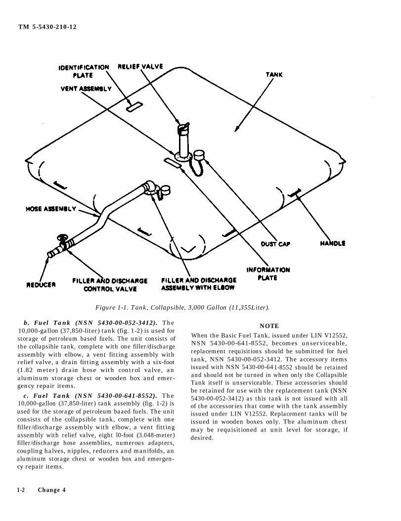
1-6. Description. collapsible tank, complete with one filler/discharge assem-bly with elbow, a vent fitting assembly with relief valve, a
a Fuel Tank (NSN 5430-00-268-8187). The fair-foot (1.219-meter) filler/discharge hose assembly3000-gallon (11,355-liter) tank (fig. 1-1) is used for the with control valve, a 4-inch (10.16 cm) female to 3-inchstroage of petroleum based fuels. The unit consists of the (7.62 cm) male reducer and emergency repair items.
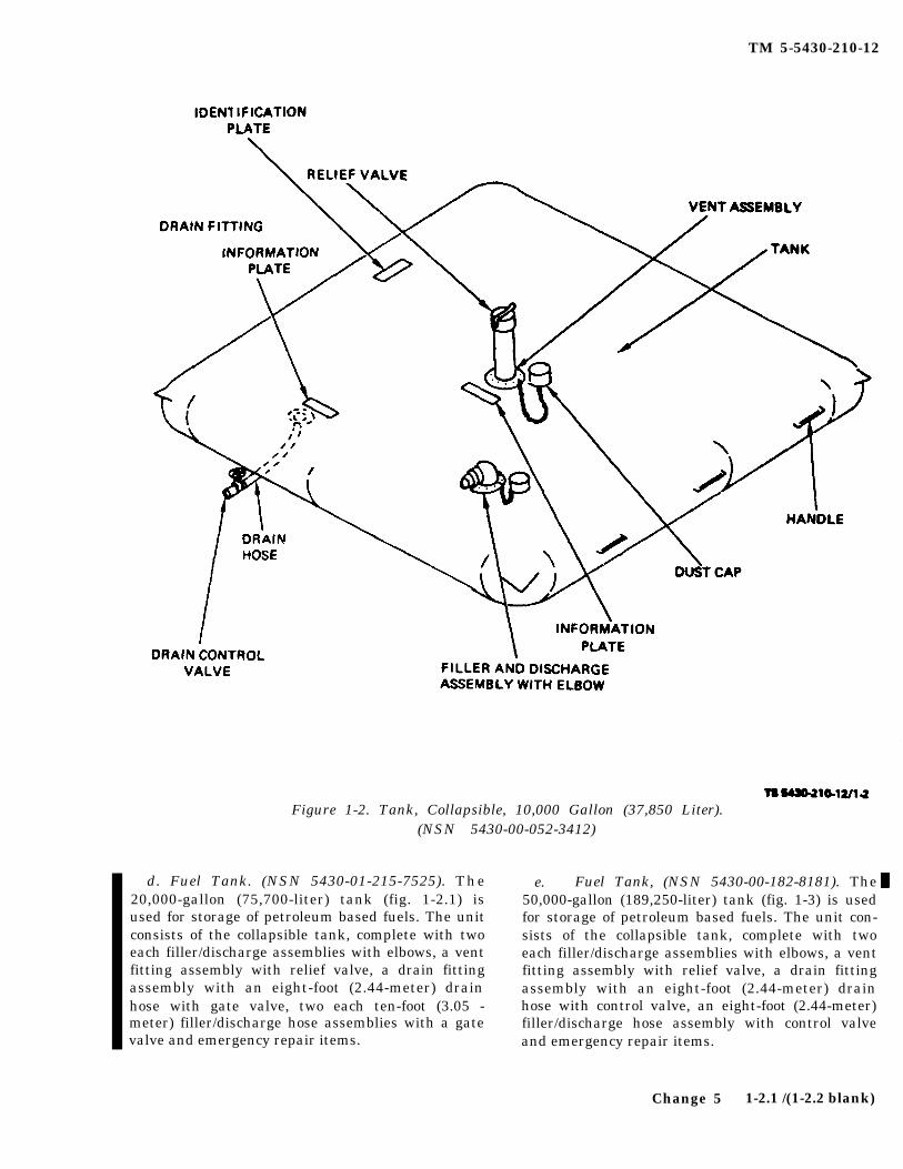
b. Fuel Tank (NSN 5430-00-052-3412). The10,000-gallon (37,850-liter) tank (fig. 1-2) is used forstorage of petroleum based fuels. The unit consists ofthe collapsible tank, complete with one filler/dischargeassembly with elbow, a vent fitting assembly withrelief valve, a drain fitting assembly with a six-foot(1.82 meter) drain hose with control valve, analuminum storage chest or wooden box and emer-gency repair items.
c. Fuel Tank (NSN 5430-00-641-8552). The10,000-gallon (37,850-liter) tank assembly (fig. 1-2) isused for the storage of petroleum baaed fuels. The unitconsists of the collapsible tank, complete with onefiller/discharge assembly with elbow, a vent fittingassembly with relief valve, eight l0-foot (3.048-meter)filler/discharge hose assemblies, numerous adapters,coupling halves, nipples, reducers and manifolds, analuminum storage chest or wooden box and emergen-cy repair items.
NOTEWhen the Basic Fuel Tank, issued under LIN V12552,NSN 5430-00-641-8552, becomes unserviceable,replacement requisitions should be submitted for fueltank, NSN 5430-00-052-3412. The accessory itemsissued with NSN 5430-00-641-8552 should be retainedand should not be turned in when only the CollapsibleTank itself is unserviceable. These accessories shouldbe retained for use with the replacement tank (NSN5430-00-052-3412) as this tank is not issued with allof the accessories that come with the tank assemblyissued under LIN V12552. Replacement tanks will beissued in wooden boxes only. The aluminum chestmay be requisitioned at unit level for storage, ifdesired.
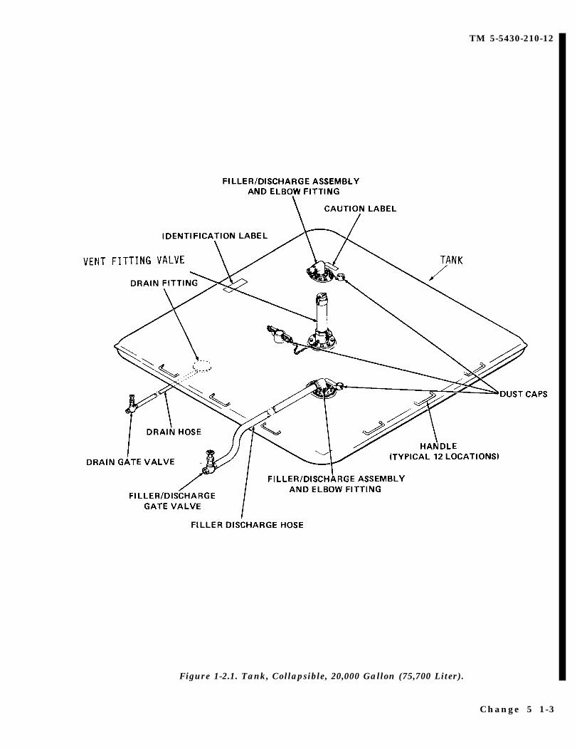
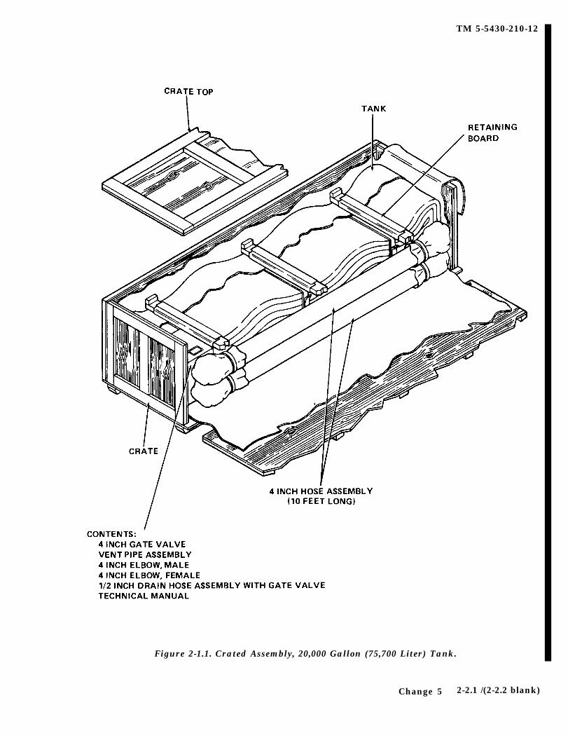
d. Fuel Tank. (NSN 5430-01-215-7525). The20,000-gallon (75,700-liter) tank (fig. 1-2.1) isused for storage of petroleum based fuels. The unitconsists of the collapsible tank, complete with twoeach filler/discharge assemblies with elbows, a ventfitting assembly with relief valve, a drain fittingassembly with an eight-foot (2.44-meter) drainhose with gate valve, two each ten-foot (3.05 -meter) filler/discharge hose assemblies with a gatevalve and emergency repair items.
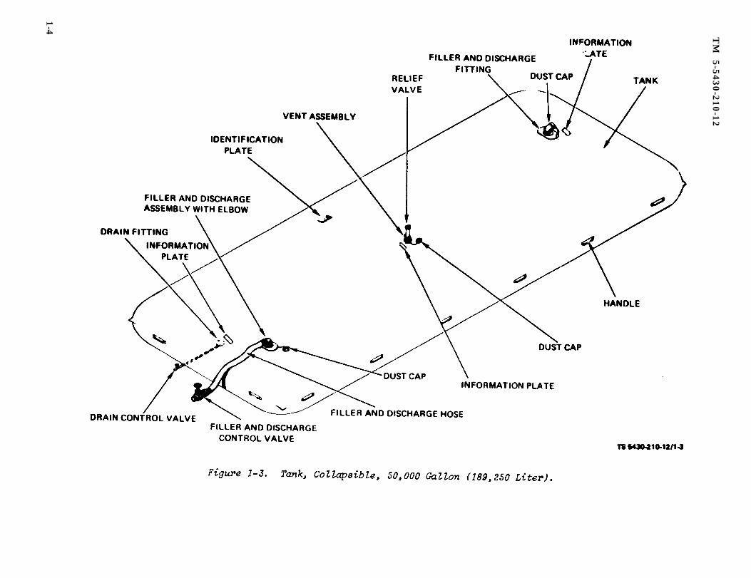
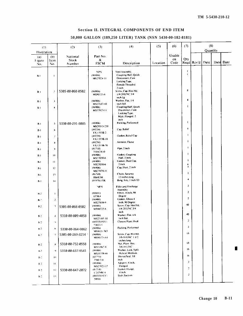
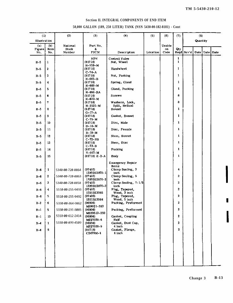
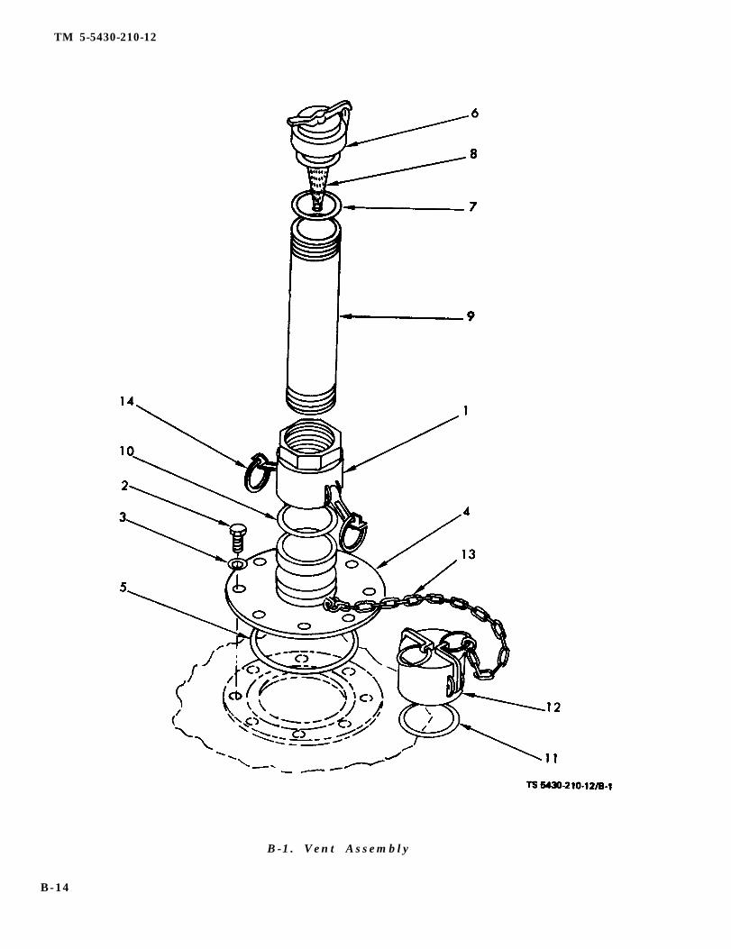
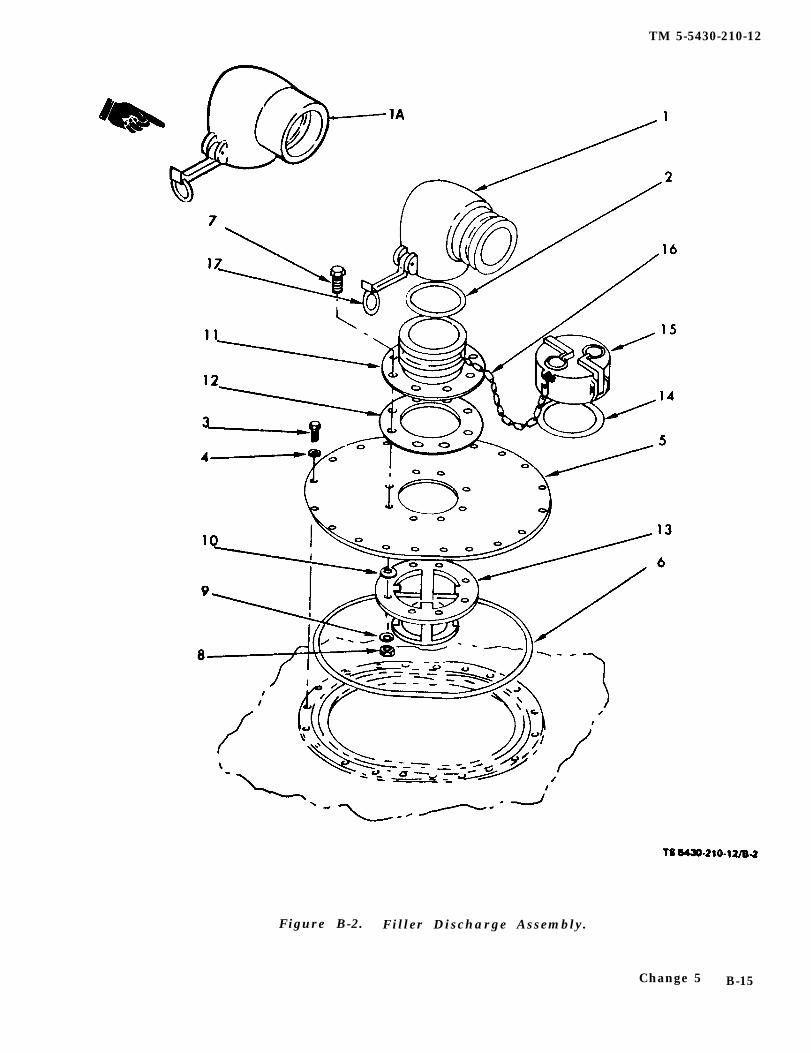
e. Fuel Tank, (NSN 5430-00-182-8181). The50,000-gallon (189,250-liter) tank (fig. 1-3) is usedfor storage of petroleum based fuels. The unit con-sists of the collapsible tank, complete with twoeach filler/discharge assemblies with elbows, a ventfitting assembly with relief valve, a drain fittingassembly with an eight-foot (2.44-meter) drainhose with control valve, an eight-foot (2.44-meter)filler/discharge hose assembly with control valveand emergency repair items.
2-1. General. When a new or used tank is receivedby an organization, it must be unpacked, inspectedand serviced.
2-2. Unpacking the Equipment. When the tank isreceived in a chest or crate, unload it as near to itspoint of installation as is possible.
CAUTIONUse extreme caution when unfoldingcollapsible POL tanks due to the pos-
sibility that the coated surfaces mayhave a tendency to stick together.Consequently, if excessive force is ex-erted, delamination can occur. A lightapplication of vaseline jelly will pre-vent reoccurrence.
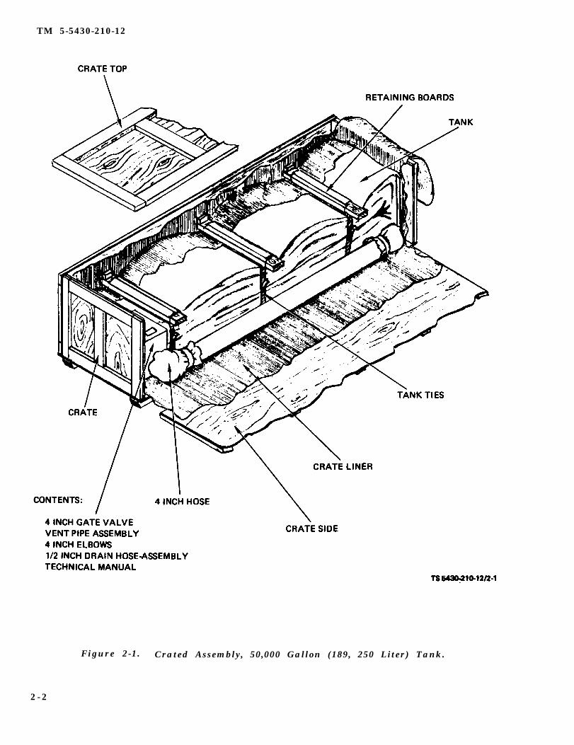
a. Tank (NSN 5430-00-182-8181).
(1) Remove the nails from the crate top andremove crate top from the crate (fig. 2- 1).
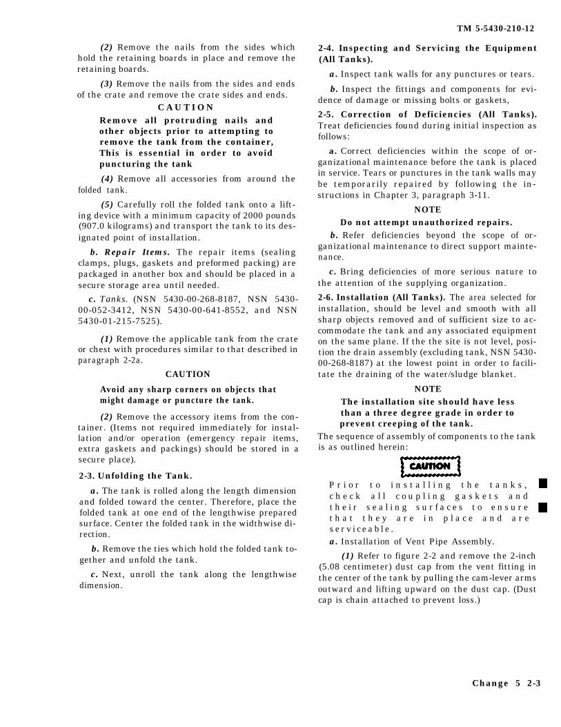
(2) Remove the nails from the sides whichhold the retaining boards in place and remove theretaining boards.
(3) Remove the nails from the sides and endsof the crate and remove the crate sides and ends.
C A U T I O NRemove all protruding nails andother objects prior to attempting toremove the tank from the container,This is essential in order to avoidpuncturing the tank
(4) Remove all accessories from around thefolded tank.
(5) Carefully roll the folded tank onto a lift-ing device with a minimum capacity of 2000 pounds(907.0 kilograms) and transport the tank to its des-ignated point of installation.
b. Repair Items. The repair items (sealingclamps, plugs, gaskets and preformed packing) arepackaged in another box and should be placed in asecure storage area until needed.
c. Tanks. (NSN 5430-00-268-8187, NSN 5430-00-052-3412, NSN 5430-00-641-8552, and NSN5430-01-215-7525).
(1) Remove the applicable tank from the crateor chest with procedures similar to that described inparagraph 2-2a.
CAUTION
Avoid any sharp corners on objects thatmight damage or puncture the tank.
(2) Remove the accessory items from the con-tainer. (Items not required immediately for instal-lation and/or operation (emergency repair items,extra gaskets and packings) should be stored in asecure place).
2-3. Unfolding the Tank.
a. The tank is rolled along the length dimensionand folded toward the center. Therefore, place thefolded tank at one end of the lengthwise preparedsurface. Center the folded tank in the widthwise di-rection.
b. Remove the ties which hold the folded tank to-gether and unfold the tank.
c. Next, unroll the tank along the lengthwisedimension.
TM 5-5430-210-12
2-4. Inspecting and Servicing the Equipment(All Tanks).
a. Inspect tank walls for any punctures or tears.
b. Inspect the fittings and components for evi-dence of damage or missing bolts or gaskets,
2-5. Correction of Deficiencies (All Tanks).Treat deficiencies found during initial inspection asfollows:
a. Correct deficiencies within the scope of or-ganizational maintenance before the tank is placedin service. Tears or punctures in the tank walls maybe temporarily repaired by following the in-structions in Chapter 3, paragraph 3-11.
NOTEDo not attempt unauthorized repairs.
b. Refer deficiencies beyond the scope of or-ganizational maintenance to direct support mainte-nance.
c. Bring deficiencies of more serious nature tothe attention of the supplying organization.
2-6. Installation (All Tanks). The area selected forinstallation, should be level and smooth with allsharp objects removed and of sufficient size to ac-commodate the tank and any associated equipmenton the same plane. If the the site is not level, posi-tion the drain assembly (excluding tank, NSN 5430-00-268-8187) at the lowest point in order to facili-tate the draining of the water/sludge blanket.
NOTEThe installation site should have lessthan a three degree grade in order toprevent creeping of the tank.
The sequence of assembly of components to the tankis as outlined herein:
P r i o r t o i n s t a l l i n g t h e t a n k s ,c h e c k a l l c o u p l i n g g a s k e t s a n dt h e i r s e a l i n g s u r f a c e s t o e n s u r et h a t t h e y a r e i n p l a c e a n d a r es e r v i c e a b l e .a. Installation of Vent Pipe Assembly.
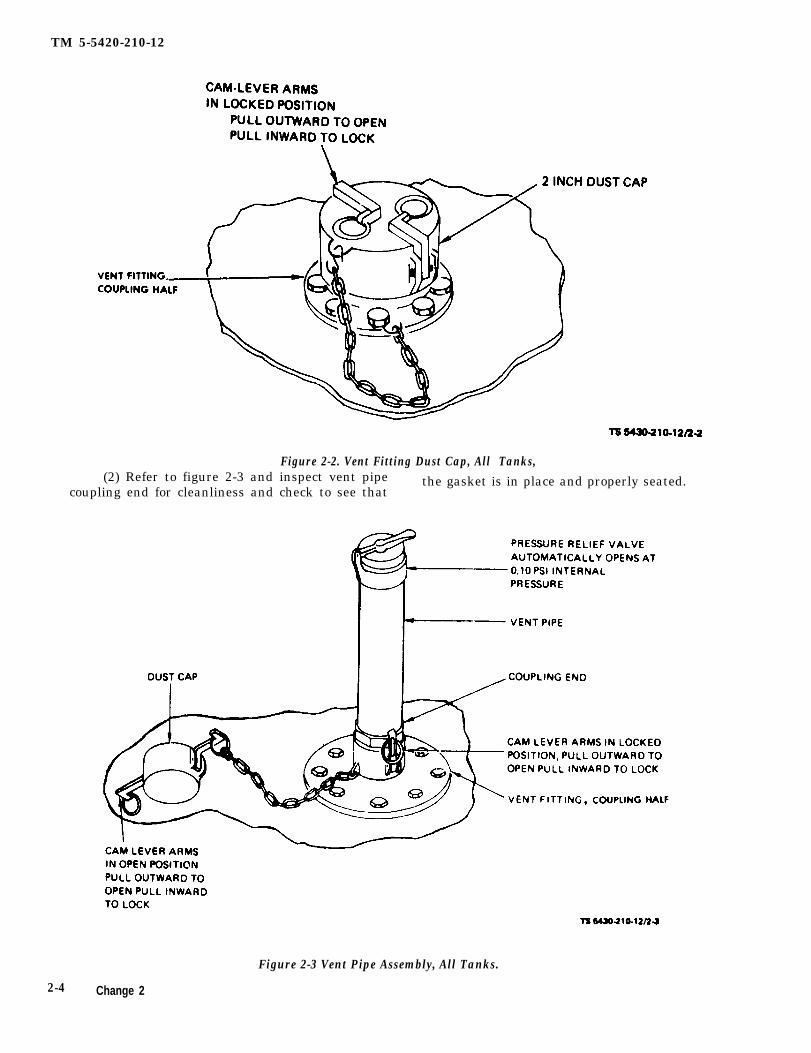
(1) Refer to figure 2-2 and remove the 2-inch(5.08 centimeter) dust cap from the vent fitting inthe center of the tank by pulling the cam-lever armsoutward and lifting upward on the dust cap. (Dustcap is chain attached to prevent loss.)
Change 5 2-3
TM 5-5420-210-12
Figure 2-2. Vent Fitting Dust Cap, All Tanks,(2) Refer to figure 2-3 and inspect vent pipe the gasket is in place and properly seated.
coupling end for cleanliness and check to see that
Figure 2-3 Vent Pipe Assembly, All Tanks.
2-4 Change 2
TM 5-5430-210-12
(3) Check to see that the pressure relief valve into operating position.is screwed tightly on the vent pipe. b. Installation of Filler and Discharge Elbow As-
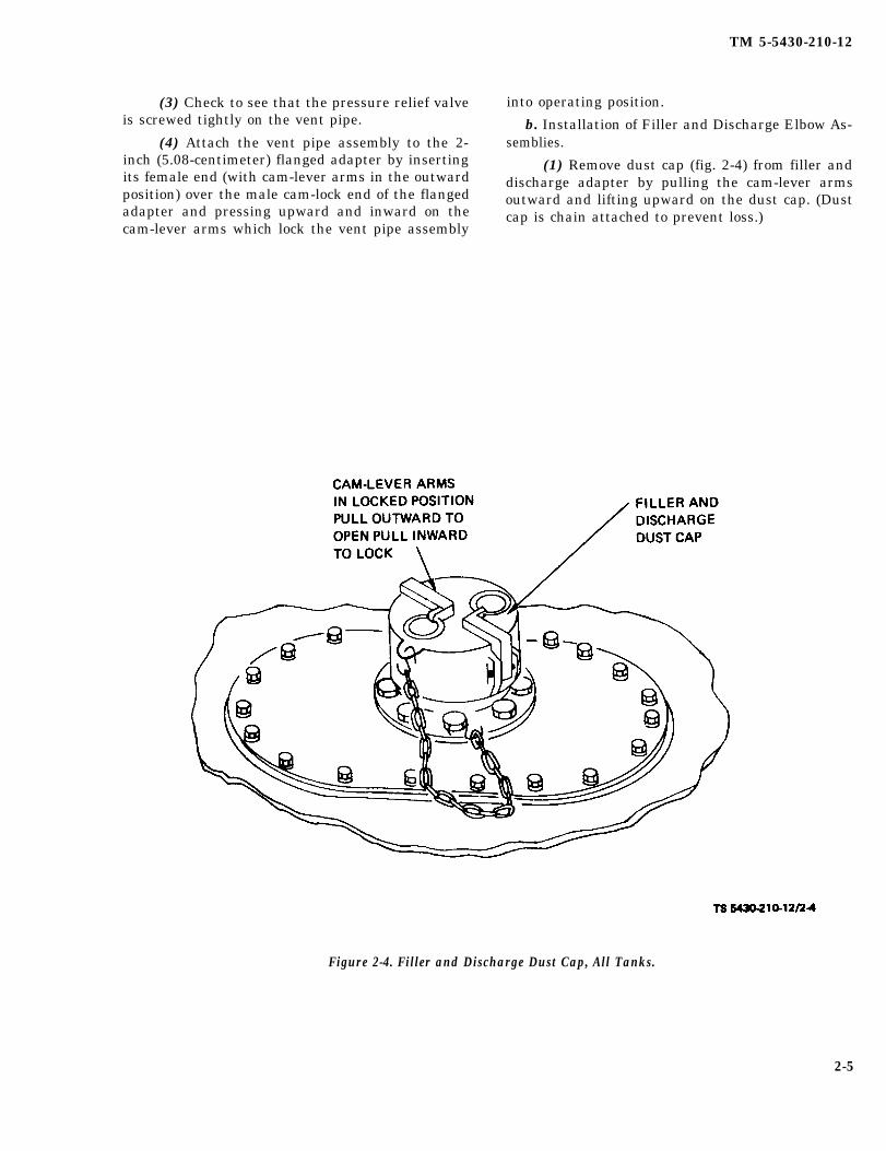
(4) Attach the vent pipe assembly to the 2- semblies.inch (5.08-centimeter) flanged adapter by inserting (1) Remove dust cap (fig. 2-4) from filler andits female end (with cam-lever arms in the outward discharge adapter by pulling the cam-lever armsposition) over the male cam-lock end of the flanged outward and lifting upward on the dust cap. (Dustadapter and pressing upward and inward on the cap is chain attached to prevent loss.)cam-lever arms which lock the vent pipe assembly
Figure 2-4. Filler and Discharge Dust Cap, All Tanks.
2-5
TM 5-5430-210-12
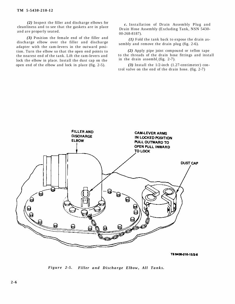
(2) Inspect the filler and discharge elbows for c. Installation of Drain Assembly Plug andcleanliness and to see that the gaskets are in place Drain Hose Assembly (Excluding Tank, NSN 5430-and are properly seated. 00-268-8187).
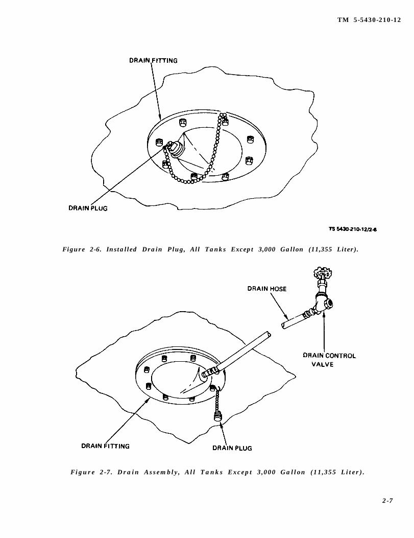
(3) Position the female end of the filler and (1) Fold the tank back to expose the drain as-discharge elbow over the filler and discharge sembly and remove the drain plug (fig. 2-6).adapter with the cam-levers in the outward posi-
(2) Apply pipe joint compound or teflon tapetion. Turn the elbow so that the open end points tothe nearest end of the tank. Lift the cam-levers and to the threads of the drain hose fittings and installlock the elbow in place. Install the dust cap on the in the drain assembly (fig. 2-7).
(3) Install the 1/2-inch (1.27-centimeter) con-open end of the elbow and lock in place (fig. 2-5).trol valve on the end of the drain hose. (fig. 2-7)
Figure 2-5. Filler and Discharge Elbow, All Tanks.
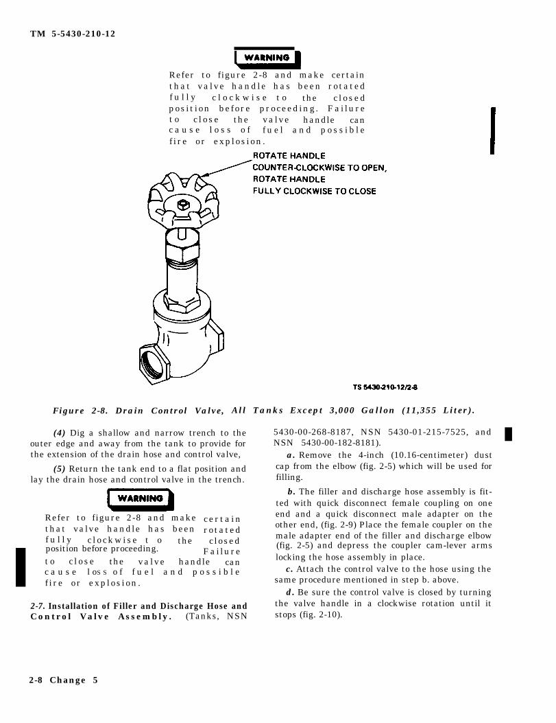
Refer to figure 2-8 and make certainthat va lve handle has been rotatedf u l l y c l o c k w i s e t o the c l o s e dpos i t ion be fore proceeding . Fai luret o c l o s e the valve handle canc a u s e l o s s o f f u e l a n d p o s s i b l ef i re or exp los ion .
Figure 2-8. Drain Control Valve, All Tanks Except 3,000 Gallon (11,355 Liter).
(4) Dig a shallow and narrow trench to the 5430-00-268-8187, NSN 5430-01-215-7525, and outer edge and away from the tank to provide for NSN 5430-00-182-8181).the extension of the drain hose and control valve, a. Remove the 4-inch (10.16-centimeter) dust
(5) Return the tank end to a flat position and cap from the elbow (fig. 2-5) which will be used forlay the drain hose and control valve in the trench. filling.
Refer to figure 2-8 and makethat valve handle has beenf u l l y c l o c k w i s e t o the
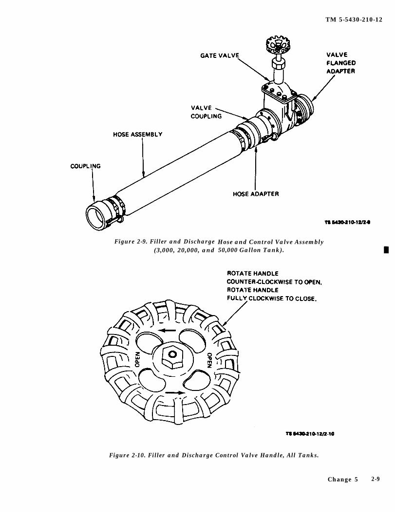
b. The filler and discharge hose assembly is fit-ted with quick disconnect female coupling on one
c e r t a i n end and a quick disconnect male adapter on theother end, (fig. 2-9) Place the female coupler on therotatedmale adapter end of the filler and discharge elbowclosed (fig. 2-5) and depress the coupler cam-lever arms
Fai luret o handle locking the hose assembly in place.c l o s e the valve canc a u s e l oS S o f f u e l a n d p o s s i b l e c. Attach the control valve to the hose using the
f i re or exp los ion . same procedure mentioned in step b. above.d. Be sure the control valve is closed by turning
2-7. Installation of Filler and Discharge Hose and the valve handle in a clockwise rotation until itControl Valve Assembly. (Tanks, NSN stops (fig. 2-10).
2-8 Change 5
position before proceeding.
TM 5-5430-210-12
Figure 2-9. Filler and Discharge(3,000, 20,000, and
Hose and Control Valve Assembly50,000 Gallon Tank).
Figure 2-10. Filler and Discharge Control Valve Handle, All Tanks.
Change 5 2-9
TM 5-5430-210-12
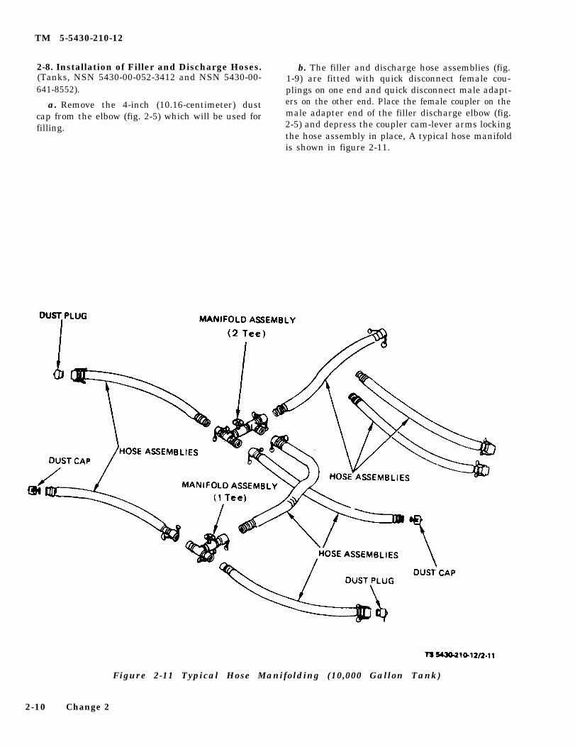
2-8. Installation of Filler and Discharge Hoses. b. The filler and discharge hose assemblies (fig.(Tanks, NSN 5430-00-052-3412 and NSN 5430-00- 1-9) are fitted with quick disconnect female cou-641-8552). plings on one end and quick disconnect male adapt-
a. Remove the 4-inch (10.16-centimeter) dust ers on the other end. Place the female coupler on the
cap from the elbow (fig. 2-5) which will be used for male adapter end of the filler discharge elbow (fig.
filling. 2-5) and depress the coupler cam-lever arms lockingthe hose assembly in place, A typical hose manifoldis shown in figure 2-11.
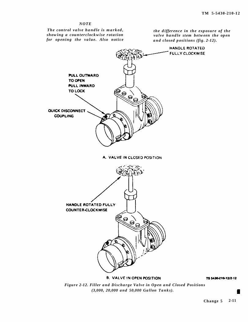
NOTEThe control valve handle is marked, the difference in the exposure of theshowing a counterclockwise rotation valve handle stem between the openfor opening the value. Also notice and closed positions (fig. 2-12).
Figure 2-12. Filler and Discharge Valve in Open and Closed Positions(3,000, 20,000 and 50,000 Gallon Tanks).
Change 5 2-11
TM 5-5430-210-12
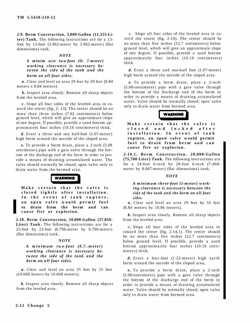
2-9. Berm Construction, 3,000-Gallon (11,355-Li-ter) Tank. The following instructions are for a 13-foot by 13-foot (3.962-meter by 3.962-meter) (flatdimensions) tank.
NOTEA minim urn two-foot (O. 7-meter)working clearance is necessary be-tween the side of the tank and theberm on all four sides.
a. Clear and level an area 29 feet by 29 feet (8.84meters x 8.84 meters)
b. Inspect area closely. Remove all sharp objectsfrom the leveled area.
c. Slope all four sides of the leveled area in to-ward the center (fig. 2- 13). The center should be nomore than three inches (7.62 centimeters) belowground level, which will give an approximate slopeof one degree, If possible, provide a sand bottom ap-proximately four inches (10.16 centimeters) thick.
d. Erect a three and one half-foot (1.07-meter)high berm around the outside of the sloped area.
e. To provide a berm drain, place a 2-inch (5.08centimeter) pipe with a gate valve through the bot-tom of the discharge end of the berm in order to pro-vide a means of draining accumulated water. Thevalve should normally be closed; open valve only todrain water from the bermed area.
M a k e c e r t a i n t h a t t h e v a l v e i sclosed tightly after installation.I n t h e e v e n t o f t a n k r u p t u r e ,an open valve would permit fuelto drain from the berm and cancause fire or explosion.
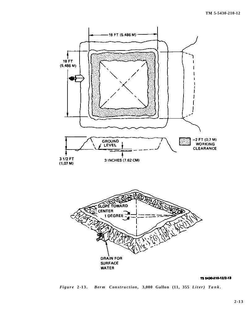
2-10. Berm Construction, 10,000-Gallon (37,850-Liter) Tank. The following instructions are for a22-foot by 22-foot (6.706-meter by 6.706-meter)(flat dimensions) tank.
NOTEA minimum two-foot (0.7.-meter)working clearance is necessary be-tween the side of the tank and theberm on all four sides.
a. Clear and level an area 35 feet by 35 feet(10.668 meters by 10.668 meters).
b. Inspect area closely. Remove all sharp objectsfrom the leveled area.
c.ward
Slope all four sides of the leveled area in to-the center (fig. 2-14). The center should be
no more than five inches (12.7 centimeters) belowground level, which will give an approximate slopeof one degree. If possible, provide a sand bottomapproximately four inches (10.16 centimeters)thick.
d. Erect a three and one-half foot (1.07-meter)high berm around the outside of the sloped area.
e. To provide a berm drain, place a 2-inch(5.08-centimeter) pipe with a gate valve throughthe bottom of the discharge end of the berm inorder to provide a means of draining accumulatedwater. Valve should be normally closed; open valveonly to drain water from bermed area.
M a k e c e r t a i n t h a t t h e v a l v e i sc l o s e d a n d l o c k e d a f t e ri n s t a l l a t i o n . I n e v e n t o f t a n krupture, an open valve would permitfuel to drain from berm and cancause fire or explosion.
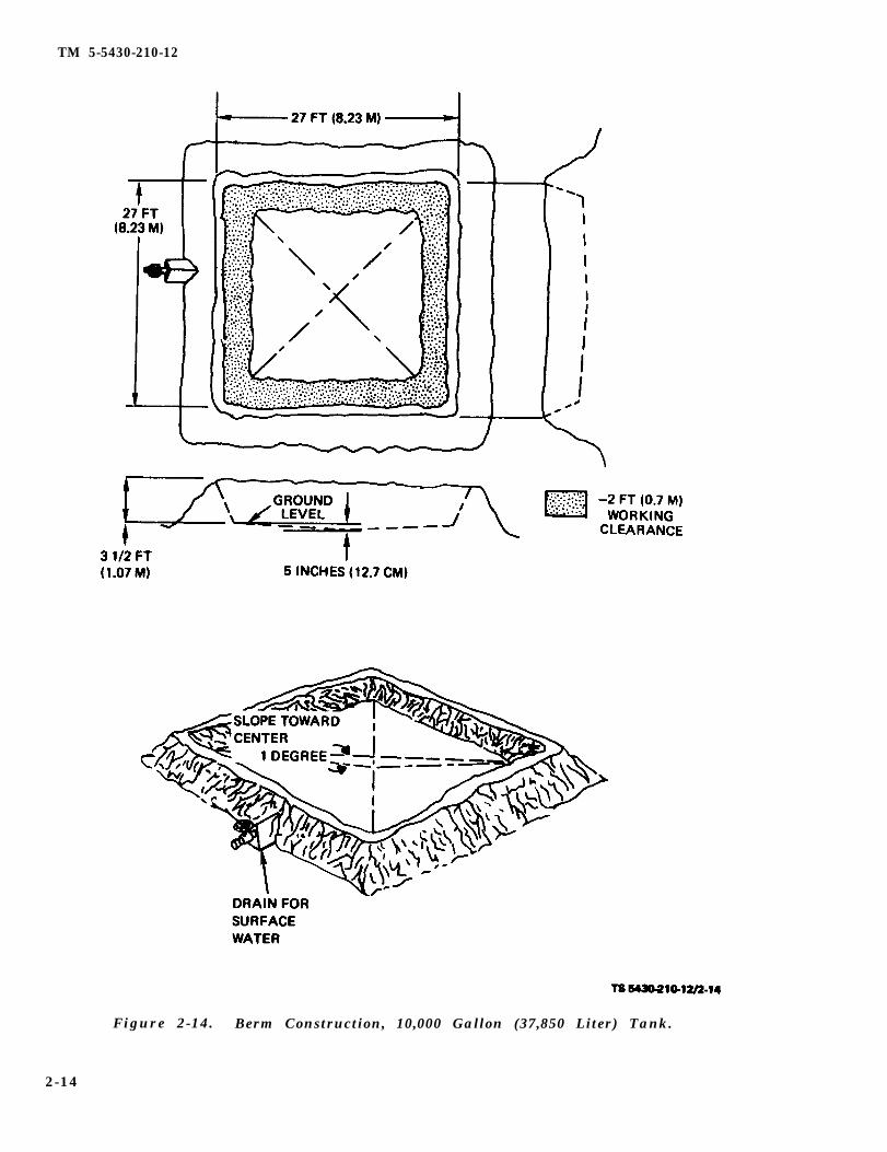
2-10.1. Berm Construction, 20,000-Gallon(75,700 Liter) Tank. The following instructions arefor a 24-foot 6-inch by 28-foot 6-inch (7.468-meter by 8.687-meter) (flat dimensions) tank.
NOTE
A minimum three-foot (1-meter) work-ing clearance is necessary between theside of the tank and the berm on all foursides.
a. Clear and level an area 29 feet by 33 feet(8.84 meters by 10.06 meters).
b. Inspect area closely. Remove all sharp objectsfrom the leveled area.
C. Slope all four sides of the leveled area intoward the center (fig. 2-14,1). The center shouldbe no more than five inches (12.7 centimeters)below ground level. If possible, provide a sandbottom approximately four inches (10.16 centi-meters) thick.
d. Erect a four-foot (1.22-meter) high earthberm around the outside of the sloped area,
e. To provide a berm drain, place a 2-inch(5.08-centimeter) pipe with a gate valve throughthe bottom of the discharge end of the berm inorder to provide a means of draining accumulatedwater. Valve should be normally closed; open valveonly to drain water from bermed area.
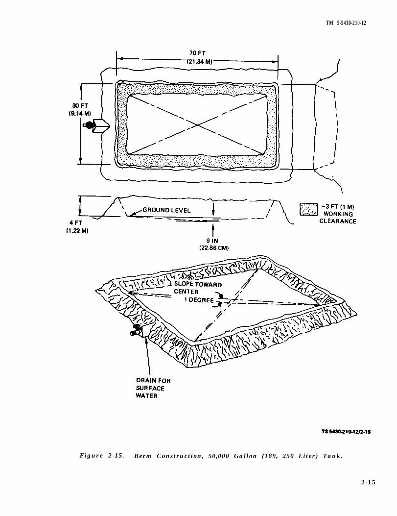
2-11. Berm Construction, 50,000-Gallon(189,250-Liter) Tank. The following instructionsare for a 26-foot by 66-foot (7.924-meter x20.117-meter) (flat dimensions).
NOTE
A minimum of three-foot (one-meter)working clearance is necessary betweenthe side of the tank and the berm on allfour sides.
a. Clear and level an area 30 feet by 70 feet(9.14 meters x 21.34 meters).
b. Inspect area closely. Remove all sharp objectsfrom the leveled area.
c. Slope all four sides of the leveled area in to-ward the center (fig. 2-15). The center should be nomore than nine inches (22.86 centimeters) belowground level. If possible, provide a sand bottom ap-proximately four inches (10.16 centimeters) thick.
d. Erect a four-foot (1.22-meter) highberm around the outside of the sloped area.
earth
e. To provide a berm drain, place a 2-inch(5.08-centimeter) pipe with a gate valve throughthe bottom of the discharge end of the berm inorder to provide a means of draining accumulated water. Valve should be normally closed; open valveonly to drain water from the bermed area.
M a k e c e r t a i n t h a t t h e v a l v e i sc l o s e d a n d l o c k e d a f t e ri n s t a l l a t i o n . I n v e n t o f t a n krupture, an open valve would permitfuel to drain from berm and couldcause fire or explosion.
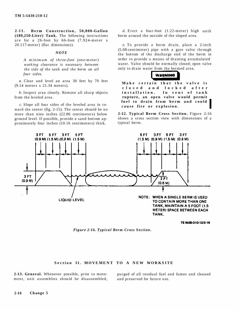
2-12. Typical Berm Cross Section. Figure 2-16shows a cross section view with dimensions of atypical berm.
Figure 2-16. Typical Berm Cross Section.
Section II . MOVEMENT TO A NEW WORKSITE
2-13. General. Whenever possible, prior to move- purged of all residual fuel and fumes and cleanedment, unit assemblies should be disassembled, and preserved for future use.
2-16 Change 5
2-14.
TM 5-543010-12
Section III. OPERATING PROCEDURES
If equipment fails to operate, refer totroubleshooting, procedures in Chapter 3,Section III.
General. The operator should be thoroughlyfamiliar with the location and function of every ;on-trol before operating the system. Other personnelcomprising the crew should be thoroughly briefed inthe operation of the system and be familiar with anyshutdown or stopping procedures under emergencyconditions.
2-15. Controls and Instruments.a. Filler and Discharge Valve (Tanks, NSN
5430-00-268-8187, NSN 5430-01-215-7525, and NSN5430-00-182-8181). The filler and discharge controlvalve (fig. 2-12) is the shut-off mechanism between thecollapsible tank and any other portion of the system.The filler and discharge control valves for tanks, NSN5430-00-052-3412 and NSN 5430-00-641-8552 and alsotypically illustrated in figure 2-12.
b. Vent Assembly (All Tanks). The vent assembly(fig. 2-3) contains a pressure relief cap which openswhen the tank is subjected to an internal pressure of0.10 psi (0.00680 atmospheres).
c. Drain Control Valve (Excluding Tank NSN5430-00-268-8187). The drain control valve allows theresidual fuel or water and sludge blanket to be drain-ed from the tank when it becomes necessary (fig. 2-8).
2-16.a.
Operation.Filling Tank (All Tanks).
Over age tanks can become weakened andrupture, thereby spilling flammable fuel onthe ground. Care must be taken to ensurethat over age tanks are not left in opera-tion. Failure to heed this warning can causeinjury or death to personnel.
Persons operating the tank mustperiodically check dates on data plates toverify that the tank is safe for use. Eachtank has a one (1) year service life begin-ning on the date when it is first filled. Shelfstorage life is five (5) years from the date ofmanufacture. Users must initiate action to
replace over age tanks. Failure to heed thiscaution can cause tank rupture.
(1) Inspect tank to verify that it is set up asshown in figures 1-1, 1-2, 1-2.1, or 1-3.
(2) Check drain control valve (fig 2-8) to verifythat it is in closed position. (Excluding Tank, NSN5430-00-268-8187.)
(3) Check the vent assembly pressure relief valve(fig. 2-3) to verify freedom of operation.
(4) Check the filler and discharge elbow at the op-posite end of tank to verify the installation of dust cap(fig. 2-5). (Tanks, NSN 5430-00-182-8181 and NSN5430-01-215-7525 only.)
(5) Check the control valve (figs. 2-10 and 2-11)to verify it is in the closed position.
(6) Attach source of fuel to the control valve.(7) Activate source of fuel.(8) Open the control valve by turning handle
counterclockwise (fig. 2-12).
(9) Close the control valve when tank is filled.NOTE
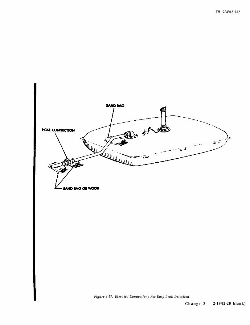
Place a filled sandbag under the fillerdischarge elbow as shown in figure 2-17.This support will reduce the stress on thetank fitting, gasket in the hose coupling,and the filler-discharge elbow coupling. Itis also recommended that hose connectionson the ground be elevated slightly byplacing sandbags or blocks of wood underthe connection. This will make a bad con-nection or a leaking connection much easierto see and avoid creating a fire hazard.
(10) Deactivate source of fuel.(11) Disconnect source of fuel from the control
valve.b. Emptying Tank (All Tanks)
(1) Inspect tank to verify that it is set upproperly.
(2) Attach emptying source to the control valve.
(3) Open the control valve.(4) Activate emptying source.
(5) Close the control valve when tank is empty.(6) Deactivate emptying source.(7) Disconnect emptying source from the control
valve.c. Draining (Excluding Tank, NSN
5430-00-268-8187).(1) Empty fuel from tank (para. 2-15b.).(2) Disconnect the filler and discharge hose from
the elbow.
Change 6 2-17
TM 5-5430-210-12
Section III. OPERATING PROCEDURES
If equipment fails to operate, refer totroubleshooting, procedures in Chapter 3,Section III.
2-14. General. The operator should be thoroughlyfamiliar with the location and function of every con-trol before operating the system. Other personnelcomprising the crew should be thoroughly briefed inthe operation of the system and be familiar with anyshutdown or stopping procedures under emergencyconditions.
2-15. Controls and Instruments.a. Filler and Discharge Valve (Tanks, NSN
5430-00-268-8187, NSN 5430-01-215-7525, and NSN5430-00-182-8181). The filler and discharge controlvalve (fig. 2-12) is the shut-off mechanism between thecollapsible tank and any other portion of the system.The filler and discharge control valves for tanks, NSN5430-00-052-3412 and NSN 5430-00-641-8552 and alsotypically illustrated in figure 2-12.
b. Vent Assembly (All Tanks). The vent assembly(fig. 2-3) contains a pressure relief cap which openswhen the tank is subjected to an internal pressure of0.10 psi (0.00680 atmospheres).
c. Drain Control Valve (Excluding Tank NSN5430-00-268-8187). The drain control valve allows theresidual fuel or water and sludge blanket to be drain-ed from the tank when it becomes necessary (fig. 2-8).
2-16. Operation.a. Filling Tank (All Tanks).
Over age tanks can become weakened andrupture, thereby spilling flammable fuel onthe ground. Care must be taken to ensurethat over age tanks are not left in opera-tion. Failure to heed this warning can causeinjury or death to personnel.
Persons operating the tank mustperiodically check dates on data plates toverify that the tank is safe for use. Eachtank has a one (1) year service life begin-ning on the date when it is first filled. Shelfstorage life is five (5) years from the date ofmanufacture. Users must initiate action to
replace over age tanks. Failure to heed thiscaution can cause tank rupture.
(1) Inspect tank to verify that it is set up asshown in figures 1-1, 1-2, 1-2.1, or 1-3.
(2) Check drain control valve (fig 2-8) to verifythat it is in closed position. (Excluding Tank, MSN5430-00-268-8187.)
(3) Check the vent assembly pressure relief valve(fig. 2-3) to verify freedom of operation.
(4) Check the filler and discharge elbow at the op-posite end of tank to verify the installation of dust cap(fig. 2-5). I. Tanks, NSN 5430-00-182-8181 and NSN5430-01-215-7525 only.)
(5) Check the control valve (figs. 2-10 and 2-11)to verify it is in the closed position.
(6) Attach source of fuel to the control valve.
(7) Activate source of fuel.(8) Open the control valve by turning handle
counterclockwise (fig. 2-12).(9) Close the control valve when tank is filled.
NOTEPlace a filled sandbag under the fillerdischarge elbow as shown in figure 2-17.This support will reduce the stress on thetank fitting, gasket in the hose coupling,and the filler-discharge elbow coupling. Itis also recommended that hose connectionson the ground be elevated slightly byplacing sandbags or blocks of wood underthe connection. This will make a bad con-nection or a leaking connection much easierto see and avoid creating a fire hazard.
(10) Deactivate source of fuel.(11) Disconnect. source of fuel from the control
valve.b. Emptying Tank (All Tanks)
(1) Inspect tank to verify that it is set upproperly.
(2) Attach emptying source to the control valve.
(3) Open the control valve.(4) Activate emptying source.
(5) Close the control valve when tank is empty.(6) Deactivate emptying source.(7) Disconnect emptying source from the control
valve.c. Draining (Excluding Tank, NSN
5430-00-268-8187).
(1) Empty fuel from tank (para. 2-15b.).(2) Disconnect the filler and discharge hose from
the elbow.
Change 6 2-17
TM 5-5430-210-12
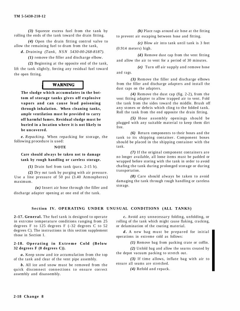
(3) Squeeze excess fuel from the tank byrolling the ends of the tank toward the drain fitting.
(4) Open the drain fitting control valve toallow the remaining fuel to dram from the tank,
d. Draining (Tank, NSN 5430-00-268-8187).(1) remove the filler and discharge elbow.
(2) Beginning at the opposite end of the tank,lift the tank slightly, forcing any residual fuel towardthe open fitting.
The sludge which accumulates in the bot-tom of storage tanks gives off explosivevapors and can cause lead poisoningthrough inhalation. When cleaning tanks,ample ventilation must be provided to carryoff harmful fumes. Residual sludge must beburied in a location where it is not likely tobe uncovered.
e. Repacking. When repacking for storage, thefollowing procedure is used:
NOTE
Care should always be taken not to damagetank by rough handling or careless storage.
(1) Drain fuel from tank (para. 2-15 b).
(2) Dry out tank by purging with air pressure.Use a line pressure of 50 psi (3.40 Atmospheres)maximum.
(a) Insert air hose through the filler anddischarge adapter opening at one end of the tank.
(b) Place rags around air hose at the fittingto prevent air escaping between hose and fitting.
(c) Blow air into tank until tank is 3 feet(0.914 meters) high.
(d) Remove dust cap from the vent fitting and allow the air to vent for a period of 30 minutes.
(e) Turn off air supply and remove hoseand rags.
(3) Remove the filler and discharge elbowsfrom the filler and discharge adapters and install thedust caps on the adapters.
(4) Remove the dust cap (fig. 2-2), from thevent fitting adapter to allow trapped air to vent. Foldthe tank from the sides toward the middle. Brush offany stones or debris which cling to the folded tank.Roll the tank from the end opposite the drain fitting.
(5) Hose assembly openings should beplugged with any suitable material to keep them dirtfree.
(6) Return components to their boxes and thetank to its shipping container. Component boxesshould be placed in the shipping container with thetank.
(7) If the original component containers areno longer available, all loose items must be padded orwrapped before storing with the tank in order to avoidchafing the tank during prolonged storage or duringtransportation.
(8) Care should always be taken to avoiddamaging the tank through rough handling or carelessstorage.
Section IV. OPERATING UNDER UNUSUAL CONDITIONS (ALL TANKS)
2–17. General. The fuel tank is designed to operate c. Avoid any unnecessary folding, unfolding, orin extrcme temperature conditions ranging from 25 rolling of the tank which might cause flaking, cracking,degrees F to 125 degrees F (–32 degrees C to 52 or delamination of the coating material.degrees C). The instructions in this section supplement d. A new bag must be prepared for initialthose in Section I. operations in extreme cold as follows:
2-18. Operating in Extreme Cold (Below (1) Remove bag from packing crate or coffin.32 degrees F (0 degrees C)). (2) Unfold bag and allow the searns created by
a. Keep snow and ice accumulation from the top the depot vacuum packing to stretch out.
of the tank and clear of the vent pipe assembly. (3) If time allows, inflate bag with air to
b. All ice and snow must be removed from the ensure all seams are stretched.
quick disconnect connections to ensure correct (4) Refold and repack.assembly and disassembly.
2-18 Change 8
TM 5-5430-210-12
e. The bag will crack if the seams are formed in 2-20. Operating in Dusty or Sandy Areas.the material from depot vacuum packing are not a. Keep all components clean, particularly atstretched out prior to the bag’s being filled with fuel. sealing and connecting points.
2-19. Operating in Extreme Heat. b. Keep all hoses and fittings covered with plugs
a. Setup protective shades over the tank and its and/or dust caps when they are not in use.
components being careful not to block air circulation. c. Cover system components when not in use.
b. Avoid any unnecessary handling which mightcause material separation. The coating materialbecomes increasingly delicate as the temperature rises.
Change 8 2-18.1/(2-18.2 blank)
TM 5-5430-210-12
Figure 2-17. Elevated Connections For Easy Leak Detection
Change 2 2-19/(2-20 blank)
TM 5-5430-210-12
CHAPTER 3
MAINTENANCE INSTRUCTIONS (ALL TANKS)
Section I. LUBRICATION INSTRUCTIONS
NOTEAll Cam Lever Pins and Lobes should be lubricatedsemi-annually with two (2) drops of OE 30 engine oil.
Section II . PREVENTIVE MAINTENANCE CHECKS AND SERVICES (PMCS)
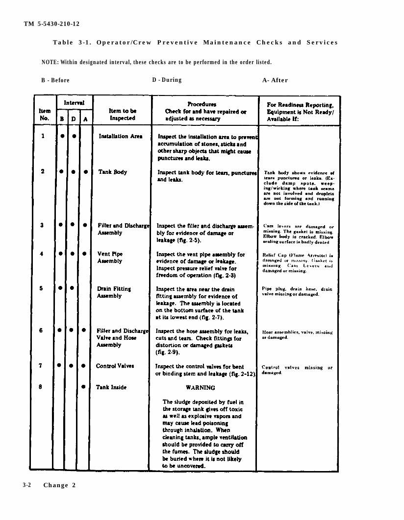
3-1. General. To ensure that the equipment isready for operation at all times, it must be inspectedsystematically so that defect may be discoveredand corrected before they result in serious damageor failure. The necessary preventive maintenancechecks and cervices are listed in table 3.1. Defectsdiscovered during operation of the system shall benoted for future correction to be made as soon asoperation has ceased. All deficiencies and short-comings will be recorded together with the cor-
rective action taken on DA Form 2404 (EquipmentInspection and Maintenance Worksheet) at the ear-liest possible opportunity.
C A U T I O NStop operation immediately if a defi-ciency is noticed which would dam-age the equipment if operations werecontinued, or jeopardize the safety ofoperating personnel.
Change 2 3-1
TM 5-5430-210-12
Table 3-1. Operator/Crew Preventive Maintenance Checks and Services
NOTE: Within designated interval, these checks are to be performed in the order listed.
B - Before D - During A- After
3-2 Change 2
TM 5-5430-210-12
Table 3-1. Operator/Crew Preventive Maintenance Checks and Services (Cont)
NOTE: Within designated interval, these checks are to be performed in the order listed.
B – Before D – During A – After
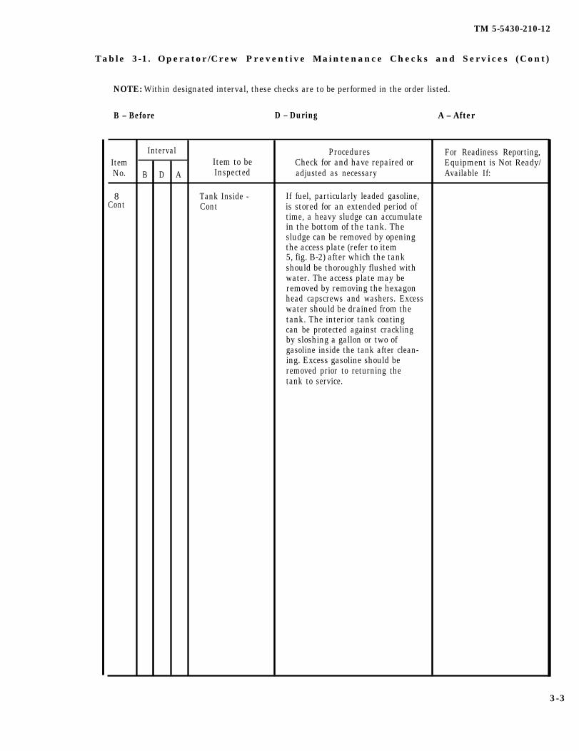
Interval Procedures For Readiness Reporting,Item Item to be Check for and have repaired or Equipment is Not Ready/No. B D A Inspected adjusted as necessary Available If:
8 Tank Inside - If fuel, particularly leaded gasoline,Cont Cont is stored for an extended period of
time, a heavy sludge can accumulatein the bottom of the tank. Thesludge can be removed by openingthe access plate (refer to item5, fig. B-2) after which the tankshould be thoroughly flushed withwater. The access plate may beremoved by removing the hexagonhead capscrews and washers. Excesswater should be drained from thetank. The interior tank coatingcan be protected against cracklingby sloshing a gallon or two ofgasoline inside the tank after clean-ing. Excess gasoline should beremoved prior to returning thetank to service.
3-3
TM 5-5430-210-12
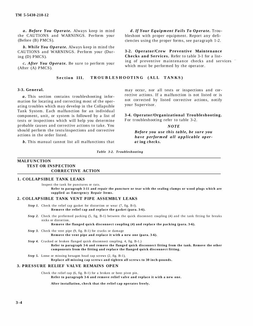
a. Before You Operate. Always keep in mind d. If Your Equipment Fails To Operate. Trou-the CAUTIONS and WARNINGS. Perform your bleshoot with proper equipment. Report any defi- (Before (B) PMCS). ciencies using the proper forms, see paragraph 1-2.
b. While You Operate. Always keep in mind theCAUTIONS and WARNINGS. Perform your (Dur- 3-2. Operator/Crew Preventive Maintenanceing (D) PMCS). Checks and Services. Refer to table 3-1 for a list-
C. After You Operate. Be sure to perform your ing of preventive maintenance checks and services —
(After (A) PMCS). which must be performed by the operator.
Section III. TROUBLESHOOTING (ALL TANKS)
3-3. General.
a. This section contains troubleshooting infor-mation for locating and correcting most of the oper-ating troubles which may develop in the CollapsibleTank System. Each malfunction for an individualcomponent, unit, or system is followed by a list oftests or inspections which will help you determineprobable causes and corrective actions to take. Youshould perform the tests/inspections and correctiveactions in the order listed.
b. This manual cannot list all malfunctions that
may occur, nor all tests or inspections and cor-rective actions. If a malfunction is not listed or isnot corrected by listed corrective actions, notifyyour Supervisor.
3-4. Operator/Organizational Troubleshooting.For troubleshooting refer to table 3-2.
NOTEBefore you use this table, be sure youhave performed all applicable oper-at ing checks.
Table 3-2. Troubleshooting
MALFUNCTIONTEST OR INSPECTION
CORRECTIVE ACTION
1. COLLAPSIBLE TANK LEAKSInspect the tank for punctures or cuts.
Refer to paragraph 3-11 and repair the puncture or tear with the sealing clamps or wood plugs which aresupplied as Emergency Repair Items.
2. COLLAPSIBLE TANK VENT PIPE ASSEMBLY LEAKS
Step 1.
Step 2.
Step 3.
Step 4.
Step 5.
Check the relief cap gasket for distortion or wear (7, fig. B-l).Remove the relief cap and replace the gasket (para. 3-6).
Check the preformed packing (5, fig, B-1) between the quick disconnect coupling (4) and the tank fitting for breaksnicks or distortion.
Remove the flanged quick disconnect coupling (4) and replace the packing (para. 3-6).
Check the vent pipe (9, fig. B-1) for cracks or damageRemove the vent pipe and replace it with a new one (para. 3-6).
Cracked or broken flanged quick disconnect coupling. 4, fig. B-1.)Refer to paragraph 3-6 and remove the flanged quick disconnect fitting from the tank. Remove the othercomponents from the fitting and replace the flanged quick disconnect fitting.
Loose or missing hexagon head cap screws (2, fig. B-1),Replace all missing cap screws and tighten all screws to 30 inch-pounds.
3. PRESSURE RELIEF VALVE REMAINS OPEN
Check the relief cap (6, fig. B-1) for a broken or bent pivot pin.Refer to paragraph 3-6 and remove relief valve and replace it with a new one.
After installation, check that the relief cap operates freely.
3-4
TM 5-5430-210-12
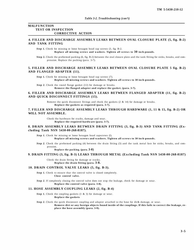
Table 3-2. Troubleshooting (con’t)
MALFUNCTIONTEST OR INSPECTION
CORRECTIVE ACTION
4. FILLER AND DISCHARGE ASSEMBLY LEAKS BETWEEN OVAL CLOSURE PLATE (5, fig. B-2)AND TANK FITTING
Step 1. Check for missing or loose hexagon head cap screws (3, fig. B-2.Replace all missing screws and washers. Tighten all screws to 30 inch-pounds.
Step 2. Check the preformed packing (6, fig. B-2) between the oval closure plate and the tank fitting for nicks, breaks, and com-pression. Replace the packing (para. 3-7).
5. FILLER AND DISCHARGE ASSEMBLY LEAKS BETWEEN OVAL CLOSURE PLATE 5 fig. B-2)AND FLANGED ADAPTER (11).
Step 1. Check for missing or loose hexagon head cap screws (7).Replace all missing screws and washers. Tighten all screws to 30 inch-pounds.
Step 2. Check the round flange gasket (12) for damage or breaks.Remove the flanged adapter and replace the gasket. (para. 3-7).
6. FILLER AND DISCHARGE ASSEMBLY LEAKS BETWEEN FLANGED ADAPTER (11, fig. B-2)AND QUICK DISCONNECT FITTINGS (15).
Remove the quick disconnect fittings and check the gaskets (2 & 14) for damage or breaks.Replace the gaskets as required (para. 3-7).
7. FILLER AND DISCHARGE ASSEMBLY LEAKS THROUGH HARDWARE (1, 11 & 15, fig. B-2) ORWILL NOT ASSEMBLE.
Check the hardware for cracks, damage and wear.Replace the required hardware (para. 3-7).
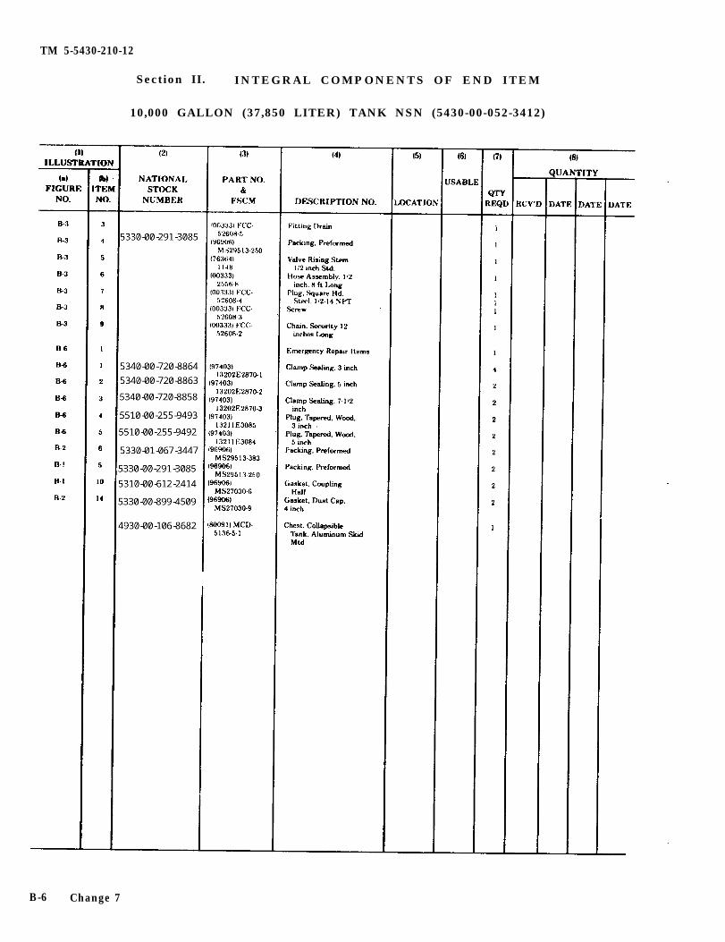
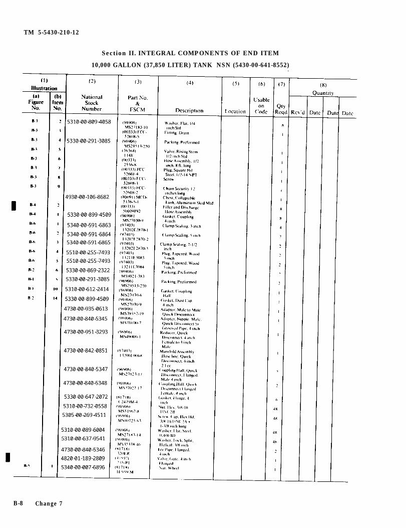
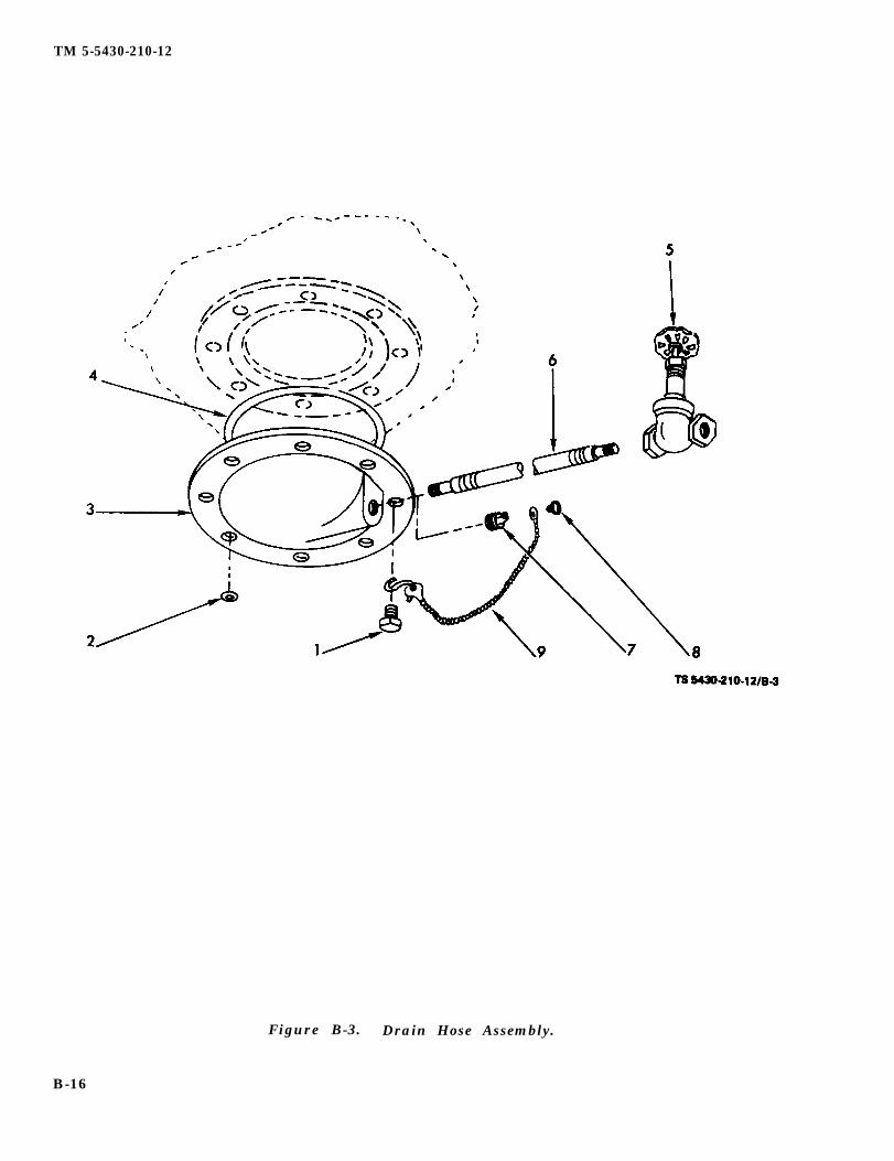
8. DRAIN ASSEMBLY LEAKS BETWEEN DRAIN FITTING (3, fig. B-3) AND TANK FITTING (Ex-cluding Tank NSN 5430-00-268-8187).
Step 1. Check for missing or loose hexagon head capscrews (l).Replace all missing screws and washers. Tighten all screws to 30 inch-pounds.
Step 2. Check the preformed packing (4) between the drain fitting (3) and the tank metal face for nicks, breaks, and com-pression.
Replace the packing. (para. 3-8)
9. DRAIN FITTING (3, fig. B-3) LEAKS THROUGH METAL (Excluding Tank NSN 5430-00-268-8187)
Check the drain fitting for damage or cracks.Replace the drain fitting (para. 3-8.
10. DRAIN CONTROL VALVE LEAKS (5, fig. B-3).
Step 1. Check to ensure that the control valve is closed completely.Close control valve.
Step 2. If completely closing the control valve does not stop the leakage, check for damage or wear.Replace the control valve (para. 3-8).
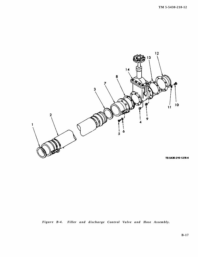
11. HOSE ASSEMBLY COUPLING LEAKS (2, fig. B-4)
Step 1. Check the coupling gaskets (1 & 3) for damage or wear.Replace the gaskets
Step 2. Check the quick disconnect coupling and adapter attached to the hose for dir& damage, or wear.Remove dirt or any foreign objects found inside of the couplings. If this fails to correct the leakage, re-place the hose assembly (para. 3-9).
3-5
TM 5-5430-210-12
Table 3-2. Troubleshooting (con’t)
MALFUNCTIONTEST OR INSPECTION
CORRECTIVE ACTION
12. CONTROL VALVE ASSEMBLY COUPLING (FEMALE) LEAKS (7, fig. B-4).
Step 1. Check the coupling for miming or loose hexagon head cap screws (4 and 5).Replace all missing screws and nuts. Tighten all screws and nuts to 30 inch-pounds.
Step 2. Check the round flange gasket (8) for damage or breaks,Replace the flanged coupling and replace the gasket (para. 3-9).
13. CONTROL VALVE ASSEMBLY ADAPTER (MALE) LEAKS (12, fig. B-4).
Step 1. Check the adapter for miming or lame hexagon head cap nut and screws (9 & 10).Replace all missing screws and nuts. Tighten all screws and nuts to 30 inch-pounds.
Step 2. Check the round flanged gasket (13) for damage or breaks.Remove the flanged adapter and replace the gasket (para. 3-9).
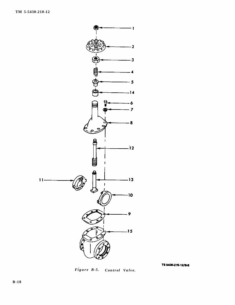
14. CONTROL VALVE LEAKS
Step 1. Check for loose or missing screws (6, fig. B-5) on the valve bonnet (8).Tighten or replace missing washers and bolts (para. 3-10).
Step 2. Check for damaged or distorted bonnet gasket (9).Replace bonnet gasket (para. 3-10)
Step 3. Check for bent or distorted bonnet stem (12).Replace bonnet stem (para. 3-10).
Section IV. M A I N T E N A N C E
3-5. General. This section contains maintenanceand repair instructions for the four collapsible POLtanks.
3-6. Vent Assembly (All Tanks).
a. Disassembly.
(1) Disconnect the female quick disconnectcoupling, (1, fig. B-1) from the flanged male quickdisconnect coupling (4) by pulling outward on cam-lever arms, then lift quick disconnect coupling fromthe male coupling.
(2) Remove the eight screws and washers (2and 3). Lift flanged coupling (4) from tank fitting.
(3) Remove the preformed packing (5) fromthe packing groove in the tank fitting,
(4) Separate relief cap (6) from the vent pipe(9) by turning the cap in a counter clock-wise direc-tion until threads disengage.
(5) Remove relief cap gasket (7) from the in-side of the relief cap.
(6) Turn flame arrestor (8) in a counter clock-wise direction until the threads disengage from therelief cap (6).
(7) To remove vent pipe (9) from the quick
PROCEDURES (ALL TANKS)
disconnect coupling (1), turn the vent pipe in acounterclockwise direction until threads disengage.
(8) Remove dust cap gasket (11) from insideof the dust cap (12).
b. Cleaning and Inspection.
W A R N I N GDrycleaning solvent, P-D-680, used toclean parts is potentially dangerous topersonnel and property, Avoid re-peated and prolonged skin contact.Do not use near open flame or exces-sive heat. Flash point of solvent is 100degrees F -138 degrees F (38 degrees C-59 degrees C).
(1) Clean all parts with cleaning solvent(Item 1, App. F) and dry thoroughly.
(2) Clean out preformed packing grooves thor-oughly.
(3) Inspect all mechanical parts for cracks,dents, breaks, or wear. Replace or repair, if un-serviceable.
(4) Carefully inspect gaskets and packings fordeterioration, -distortion, cracks, or breaks. Replace
3-6
TM 5-5430-210-12
when service is doubtful.
(5) Ensure that vent hole in the relief valve isclear.
c. Reassembly.
(1) Place preformed packing (5, fig. B-1) intothe packing groove in the tank fitting.
(2) Place flanged adapter (4) on the tank fit-ting Rotate flange so the holes in the flange are inline with the tapped holes in the fitting. Assemblescrews (2) through the washers (3) and through theholes in the flange and into tapped holes in the tankfitting. Tighten to 30 inch-pounds.
(3) Insert vent pipe (9) into quick disconnectcoupling (1) and turn pipe in clockwise directionuntil the two pieces are jointed together tightly.
(4) Insert flame arrestor (8) into relief cap (6)and turn flame arrestor in a clockwise directionuntil the two pieces are jointed together tightly.
(5) Place relief cap gasket (7) over flame ar-restor and seat it inside the relief cap.
(6) Place flame arrestor (8) into vent pipe (9)until vent pipe contacts the relief cap (6). Rotate re-lief cap in a clockwise direction until vent pipe andrelief cap are joined together tightly.
(7) Insert quick disconnect coupling gasket(10) into the female quick disconnect coupling (1).
(8) Ensure that the cam-lever arms of thequick disconnect coupling are in an outward posi-tion. Place coupling (with 6, 7, 8, 9 and 10 attached)onto flanged coupling (4), Pull the cam-lever armsinward until they are locked in place.
(9) Insert dust cap gasket (11) into dust cap(12).
3-7. Filler and Discharge Assembly (All Tanks).
a. Disassembly.
(1) Remove 4-inch elbow, (1, fig. B-2.), by pull-ing outward on the cam-lever arms. Lift elbow offthe flanged adapter (11).
(2) Remove elbow gasket (2) from inside ofelbow (1).
(3) Remove screws (3) and washers (4) andlift oval closure plate (5) from the collapsible tankfitting.
(4) Lift preformed packing(6) from inside thepacking groove in the tank fitting.
(5) Remove screws (7), nuts (8), and 1ock-washers (9) from remaining assembly, thereby re-leasing the suction stub (13) from the bottom of the
closure plate (5).
(6) Remove dust cap gasket (14) from insideof dust cap (15).
b. Cleaning and Inspection.
W A R N I N GDrycleaning solvent, P-D-68, used toclean parts is potentially dangerous topersonnel and property. Avoid re-peated and prolonged skin contact.Do not use near open flame or exces-sive heat. Flash point of solvent is 100degrees F -138 degrees F (38 degrees C-59 degrees C)
(2) Clean all parts with cleaning solvent(Item 1, App. F) and dry thoroughly.
(2) Clean out packing grooves thoroughly
(3) Inspect all mechanical parts for cracks,dents, breaks, or wear. Replace or repair, if un-serviceable.
(4) Carefully inspect gaskets and packings fordeterioration, distortion, cracks, or breaks. Replacewhen serviceability is doubtful.
c. Reassembly.
(1) Place dust cap gasket (14, fig. B-2) intodust cap (15).
(2) Place elbow gasket (2) into elbow (1).
(3) Place suction stub (13) on a flat hard sur-face with the bolt holes on top.
(4) Place thread seals (10) over each bolt holein suction stub (13).
(5) Place oval closure plate (5) on top ofthread seals (10) being careful to keep all holesaligned.
(6) Place flanged adapter gasket (12) on ovalclosure plate (5) and align the holes.
(7) Place flanged adapter (11) on flange gas-ket (12) and align the holes.
(8) Insert the 3/8-16 x 1 1/2 long screws (7)through the holes in (13, 10, 5, 12 and 11.)
(9) Assemble lockwashers (9) and nuts (8) toscrews (7) and tighten to 30 inch-pounds.
(10) Place preformed packing (6) into thepacking groove in collapsible tank fitting.
(11) Place the oval closure plate and its at-tached components onto tank by putting the suctionstub through the oval opening in the tank until ovalclosure plate (5) comes in contact with tank fitting.If the tank is laying completely flat, it will be neces-sary to lift the tank up to the closure plate in order
3-7
TM 5-5430-210-12
to start the screws into the tank fitting.
(12) Assemble 1/4 - 20 x 3/4 screws (3) andwashers (4). Insert screws through oval closureplate (5) and into tapped holes in the tank fitting,Tighten to 30 inch-pounds.
(13) Place elbow (1) onto flanged adapter(11). Pull inward on the cam-lever arms to lock thetwo items together.
(1) Remove screws (1, fig. B-3) and washers(2) which hold the fitting assembly to the col-lapsible tank fitting.
(2) Remove drain fitting (3) with remaininghardware attached.
(3) Remove preformed packing (4) from pack-ing groove in the tank fitting.
(4) Disconnect valve (5) from drain hose (6)by turning valve in a counterclockwise directionuntil threads disengage.
(5) Disconnect drain hose (6) from drain fit-ting (3) by rotating the hose in a counterclockwisedirection until threads disengage.
(6) To remove security chain (9) from drainplug (7), remove the roundhead screw (8).
b. Cleaning and Inspection.
W A R N I N GDrycleaning solvent, P-D-680, used toclean parts is potentially dangerous topersonnel and property. Avoid re-peated and prolonged skin contact.Do not use near open flame or exces-sive heat. Flash point of solvent is 100degrees F -138 degrees F (38 degrees C-59 degrees C)
(2) Clean all parts with drycleaning solvent(Item 1, App. F) and dry thoroughly.
(2) Clean out the packing groove thoroughly,
(3) Inspect all mechanical parts for cracks,dents, breaks or wear. Replace, or repair, if un-serviceable.
(4) Carefully inspect the packing for deterio-ration, distortion, cracks or breaks. Replace whenserviceability is doubtful.
c. Reassembly.
(1) Attach security chain (9, fig. B-3) to drainplug (7) with roundhead screw (8).
(2) Assemble drain hose (6) to the drain fit-ting by engaging the threads and rotating the hosein a clockwise direction until they are tightly join- ed.
(3) Attach valve (5) to drain hose (6) by en-gaging the thread and rotating the valve in a clock-wise direction until they are tightly joined.
(4) Place preformed packing (4) into the pack-ing groove on tank fitting.
(5) Place drain fitting (3) on tank fitting,Align the bolt holes.
(6) Insert screws (1) with washers (2) throughbolt holes and tighten to 30 inch-pounds.
(7) Insert S-hook of the security chain (9)under the head of one of the bolts (1) and tighten to30 inch-pounds.
3-9. Filler and Discharge Valve Assembly (AllTanks)
a. Disassembly.
(1) Remove hose coupling gasket (1, fig. B-4)from inside of quick disconnect coupling on hose as-sembly (2).
(2) Disconnect hose assembly (2) from flangedgate valve (14) by pulling the cam-lever arms out-ward on the female quick disconnect coupling (7)and withdraw the hose assembly (2).
(3) Remove quick disconnect coupling gasket(3) from inside the coupling (7).
(4) Remove hexagon nuts (4) from hexagonhead cap screws (5). Withdraw the screws and re-move the washers (6).
(5) Remove female quick disconnect coupling(7) and gasket (8) from the face of the valve.
(6) Remove hexagon nuts (9) from the hexa-gon head screws in the opposite end of gate valve(14). Withdraw hexagon head cap screws (10) andremove washers (11).
(7) Remove male flanged adapter (12) andflange gasket (13).
(8) Refer to paragraph 3-10 for control valvemaintenance.
b. Cleaning and Inspection.
W A R N I N GDrycleaning solvent, P-D-680, used toclean parts is potentially dangerous topersonnel and property. Avoid re-peated and prolonged skin contact.Do not use near open flame or exces-sive heat. Flash point of solvent is 100
3-8
degrees F -138 degrees F (38 degrees C-59 degrees C).
(1) Clean all parts with drycleaning solvent(Item 1, App. F) and dry thoroughly.
(2) Clean all gasket sealing surfaces thor-oughly.
(3) Inspect all mechanical parts for cracks,dents, breaks, or wear. Replace or repair if un-serviceable.
(4) Carefully inspect the gaskets for deterio-ration, distortion, cracks, or breaks. Replace whenserviceability is doubtful.
c. Reassembly.
(1) Place gasket (13, fig. B-4) against theflange face of gate valve (14) and align the holes.
(2) Place male flanged adapter (12) againstflange gasket (13) and align the holes.
(3) Insert hexagon head cap screws (10)through washers (11) and through adaptor (12),flange gasket (13) and gate valve (14), flange.
(4) Place hexagon nuts (9) on hexagon headscrews (10) and tighten to 30 inch-pounds.
(5) On the opposite end of flanged gate valve(14) place gasket (8) against the control valveflange face and align the holes.
(6) Place female quick disconnect coupling (7)against gasket (8) and align the holes.
(7) Insert hexagon head cap screws (5)through washers (6) and through coupling (7), gas-ket (8) and gate valve (14) flange.
(8) Place hexagon nuts (4) on the hexagonhead cap screws (5) and tighten to 30 inch-pounds.
(10) Insert hose assembly (2), male adapterend, into female quick disconnect coupling (7) of theflanged gate valve assembly and pull the cam-leverarms inward until locked.
(11) Insert quick disconnect gasket (1) intoquick disconnect coupling of the hose assembly (2).
3-10. Control Valve (All Tanks).
a. Disassembly.
(1) Remove the wheel nut (1, fig. B-5) fromthe top of the hand wheel (2).
(2) Remove hand wheel (2) from the top of thebonnet stem (12).
(3) Remove the packing nut (3) from the bon-net (8).
TM 5-5430-210-12
(4) Remove the gland spring (4), and packinggland (5) from the bonnet stem (12).
NOTEThe two (2) pieces of packing (14) willremain in the bonnet until after thebonnet stem (12), the disc stem (13)and the discs (10 and 11) have been re-moved from the bonnet.(5) Remove eight hexagon head cap screws (6)
and lockwashers (7) which hold the bonnet (8) tothe valve body (15).
(6) Lift the bonnet (8) complete with the bon-net stem (12) disc stem (13) and disc halves (10 and11) from the valve body (15).
C A U T I O NCare should be taken to grasp the bon-net stem with the left hand and, as thediscs clear the slots in the valve body,grasp them and hold them togetherwith the right hand in order to avoidtheir dropping off the disc stem anddamaging the sealing surfaces.
(7) Remove bonnet gasket (9).
(8) Remove the disc stem (13), from the bon-net stem (12) by turning the disc stem counter-clockwise.
(9) Remove the bonnet stem (12) from the bot-tom side of the bonnet (8) by turning the stemclockwise.
NOTEThe only time it should be necessary toremove the packing (14) is when it isto be replaced.(10) Remove the two pieces of packing (14) by
driving them out of the bonnet from the bottomside, with a piece of hard wood.
b. Cleaning and Inspection.
W A R N I N GDrycleaning solvent, P-D-680, used toclean parts is potentially dangerous topersonnel and property. Avoid re-peated and prolonged skin contact.Do not use near open flame or exces-sive heat. Flash point of solvent is 100degrees F -138 degrees F (38 degrees C-59 degrees C).
(1) Clean all parts with drycleaning solvent(Item 1, App. F) and dry thoroughly.
(2) Clean all gasket surfaces thoroughly.
(3) Inspect all mechanical parts for cracks,dents, breaks or wear. Replace, or repair, if un-
3-9
TM 5-5430-210-12
serviceable.
(4) Carefully inspect the gasket for deterio-ration, distortion, cracks or breaks. Replace whenservice is doubtful.
(5) Polish bonnet stem with a crocus cloth,(Item 2, App, F) then coat with grease (Item 3, App.F)
c. Reassembly.
(1) Screw disc stem (13, fig. B-5) into the bon-net stem (12) approximately four complete turns.
(2) Screw the disc stem (13) completely intothe bonnet (8),
(3) Lay the valve body (15) on its side on aclean surface.
(4) Insert the gasket (9) over the disc item(13).
(5) Install the two disc halves (10 and 11) ontothe disc stem (13) and insert the disc halves into theslot in the valve body.
(6) Bring the valve body (15) and the bonnet(8) to an erect position, align the bolt holes and thegasket bolt holes, and install the eight (8) eachhexagon head cap screws (6) and lockwashers (7)finger tight,
(7) Insert the two halves of the packing (14)onto the bonnet stem (12).
(8) Install the packing nut (3) onto the bonnetstem (12) and using the hands push the nut downonto the neck of the bonnet until the packing is wellseated into the bonnet.
(9) Remove the packing nut (3) from the bon-net stem (12) and install the packing gland (5) andthe gland spring (4) onto the stem. Install the pack-ing nut (3), hand wheel (2) and wheel nut (1) ontothe bonnet stem (12), Tighten the packing nut.
(10) Torque the eight hexagon head capscrews which hold the bonnet to the valve body to 16foot-pounds.
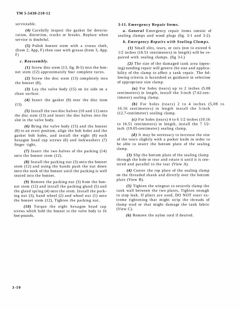
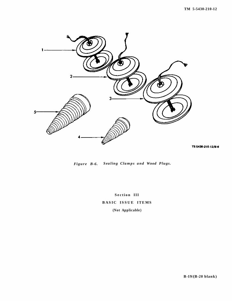
3-11. Emergency Repair Items.
a. General Emergency repair items consist ofsealing clamps and wood plugs (fig. 3-1 and 3-2).
b. Emergency Repairs with Sealing Clamps.
(1) Small slits, tears, or cuts (not to exceed 61/2 inches (16.51 centimeters) in length) will be re-paired with sealing clamps. (fig 3-l.)
(2) The size of the damaged tank area (open-ing) needing repair will govern the size and applica-bility of the clamp to affect a tank repair. The fol-lowing criteria is furnished as guidance in selectionof appropriate size clamp.
(a) For holes (tears) up to 2 inches (5.08centimeters) in length, install the 3-inch (7.62-cen-timeter) sealing clamp.
(b) For holes (tears) 2 to 4 inches (5,08 to10.16 centimeters) in length install the 5-inch(12.7-centimeter) sealing clamp.
(c) For holes (tears) 4 to 6 1/2 inches (10.16to 16.51 centimeters) in length, install the 7 l/2-inch (19.05-centimeter) sealing clamp.
(d) It may be necessary to increase the sizeof the tears slightly with a pocket knife in order tobe able to insert the bottom plate of the sealingclamp.
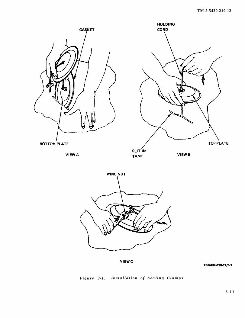
(3) Slip the bottom plate of the sealing clamp through the hole or tear and rotate it until it is cen-tered and parallel to the tear (View A).
(4) Center the top plate of the sealing clampon the threaded shank and directly over the bottomplate (View B).
(5) Tighten the wingnut to securely clamp thetank wall between the two plates, Tighten enoughto stop leak. If pliers are used, DO NOT exert ex-treme tightening that might strip the threads ofclamp stud or that might damage the tank fabric(View C).
(6) Remove the nylon cord if desired.
3-10
TM 5-5430-210-12
Figure 3-1. Installation of Sealing Clamps.
3-11
TM 5-5430-210-10
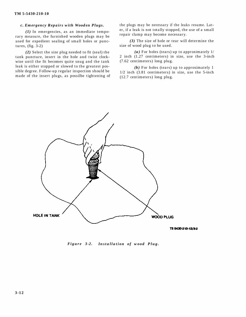
c. Emergency Repairs with Wooden Plugs.
(1) In emergencies, as an immediate tempo-rary measure, the furnished wooden plugs may beused for expedient sealing of small holes or punc-tures, (fig. 3-2)
(2) Select the size plug needed to fit (seal) thetank puncture, insert in the hole and twist clock-wise until the fit becomes quite snug and the tankleak is either stopped or slowed to the greatest pos-sible degree. Follow-up regular inspection should bemade of the insert plugs, as possilbe tightening of
the plugs may be necessary if the leaks resume. Lat-er, if a leak is not totally stopped, the use of a smallrepair clamp may become necessary.
(3) The size of hole or tear will determine thesize of wood plug to be used.
(a) For holes (tears) up to approximately 1/2 inch (1.27 centimeters) in size, use the 3-inch(7.62 centimeters) long plug.
(b) For holes (tears) up to approximately 11/2 inch (3.81 centimeters) in size, use the 5-inch(12.7 centimeters) long plug.
Figure 3-2. Installation of wood Plug.
3-12
TM 5-5430-210-12
APPENDIX A
REFERENCES
A-1. Destruction of Army Material.
TM 750-244-3
A-2. Fire Protection.
TB 5-4200-200-10
TM 5-315
A-3. Maintenance.
TM 5-343
TM 5-349
TM 5-678
TM 10-1101
TM 38-750
FM 10-20
FM 10-18
Procedures for Destruction of Equipment to Prevent Enemy Use.
Hand Portable Fire Extinguishers
Firefighting and Rescue Procedures in Theaters of Operation
Military Petroleum Pipeline Systems
Arctic Construction
Repair and Utilities - Petroleum, Oils and Lubricants
Petroleum Handling Equipment and Operations
The Army Maintenance and Management System (TAMMS)
Organizational Maintenance: Military Petroleum Pipelines, Tanks and RelatedEquipment
Petroleum Terminal and Pipeline Operations
A-4. Shipment and Storage.
TM 38-230 Preservation: Packaging and Packing of Military Supplies and Equipment
TM 38-460 Storage, Inspection and Preservation of POL Pipeline Equipment
TM 740-90-1 Administrative Storage of Equipment
A-1/(A-2 blank)
TM 5-5430-210-12
APPENDIX B
COMPONENTS OF END ITEM LIST
Section I . INTRODUCTION
B-1. Scope. This appendix lists integral com-ponents of and basic issue items for the four col-lapsible tanks to help you inventory items requiredfor safe and efficient operation.
B-2. General. This Components of End Item List isdivided into the following sections:
a. Section II. Integral Components of theEnd Item. These items, when assembled, comprisethe collapsible tank and must accompany it when-ever it is transferred or turned in. The illustrationswill help you identify these items.
b. Section III. Basic Issue Items. These are theminimum essential items required to place the col-lapsible tank in operation, to operate it, and to per-form emergency repairs. Although shipped sepa-rately packed they must accompany the collapsibletank during operation and whenever it is trans-ferred between accountable officers. The illustra-tions will assist you with hard-to- identify items.This manual is your authority to requisition re-placement BII, based on TOE/MTOE authorizationof the end item.
B-3. Explanation of Columns.
a. Illustration. Thislows:
(1) Figure Numberher of the illustration on
column is divided as fol-
Indicates the figure num-which the item is shown.
(2) Item Number. The number used to iden-tify item called out in the illustration.
b. National Stock Number. Indicates the Na-tional stock number assigned to the item and whichwill be used for requisitioning.
c. Part Number. Indicates the primary numberused by the manufacturer, which controls the design and characteristics of the item by means of itsengineering drawings, specifications, standards,and inspection requirements to identify an item orrange of items.
d. Description. Indicates the Federal itemname and, if required, a minimum description toidentify the item.
e. Location. The physical location of each itemlisted is given in this column. The lists are designedto inventory all items in one area of the major itembefore moving on to an adjacent area.
f. Usable on Code. “USABLE ON” codes are in-cluded to help you identify which component itemsare used on the different models.
g. Quantity Required (QTY Reqd). This col-umn lists the quantity of each item required for acomplete major item.
h. Quantity. This column is left blank for useduring an inventory. Under the Rcv’d column, listthe quantity you actually receive on your majoritem. The Date columns are for your use when youinventory the major item at a later date; such as forshipment to another site.
B-1
LOGSA
TM 5-5430-210-12
Section II. INTEGRAL COMPONENTS OF END ITEM
3,000 GALLON (11,355 LITER) TANK (NSN 5430-00-268-8187)
B-2 Change 10
LOGSA
5305-00-068-0502
LOGSA
5330-00-291-3085
LOGSA
5305-00-068-0502
LOGSA
LOGSA
5310-00-809-4058
LOGSA
5330-00-364-9862
LOGSA
LOGSA
5305-00-269-3214
LOGSA
5310-00-732-0558
LOGSA
5310-00637-9541
TM 5-5430-210-12
Section II INTEGRAL COMPONENTS OF END ITEM
3,000 GALLON (11,355 LITER) TANK NSN (5430-00-268-8187) - Cont
Change 3 B-3
LOGSA
5330-00-647-2072
LOGSA
5340-00-720-8864
LOGSA
5340-00-720-8863
LOGSA
5340-00-720-8858
LOGSA
5510-00-255-9493
LOGSA
5510-00-255-9492
LOGSA
5330-00-364-9862
LOGSA
5330-00-291-3085
LOGSA
4730-00-951-3293
LOGSA
5330-00-088-9166
LOGSA
4730-00-889-2378
LOGSA
TM 5-5430-210-12
Section IL INTEGRAL COMPONENTS OF END ITEM
3,000 GALLON (11,355 LITER) TANK NSN (5430-00-268-8187) - Cont
B-4
LOGSA
4730-00-889-2380
LOGSA
4730-00-929-0787
LOGSA
4820-00-075-2417
LOGSA
5330-00-075-2419
TM 5-5430-210-12
Section II. INTEGRAL COMPONENTS OF END ITEM
10,000 GALLON (37,850 LITER) TANK (NSN 5430-00-052-3412)
Change 10 B-5
LOGSA
4730-00-649-9103
LOGSA
5305-00-068-0502
LOGSA
5310-00-809-4058
LOGSA
5330-00-291-3085
LOGSA
5310-00-612-2414
LOGSA
5310-00-612-2414
LOGSA
4010-00-360-0546
LOGSA
4730-00-855-1485
LOGSA
5330-00-899-4509
LOGSA
5305-00-068-0502
LOGSA
5310-00-809-4058
LOGSA
5330-00-869-2322
LOGSA
5305-00-269-3214
LOGSA
5310-00-732-0558
LOGSA
5310-00-637-9541
LOGSA
4730-00-840-5347
LOGSA
5330-00-647-2072
LOGSA
5330-00-899-4509
LOGSA
4730-00-640-6156
LOGSA
4010-00-360-0596
LOGSA
5305-00-068-0500
LOGSA
5310-00-809-4058
TM 5-5430-210-12
Section II. INTEGRAL COMPONENTS OF END ITEM
10,000 GALLON (37,850 LITER) TANK NSN (5430-00-052-3412)
B-6 Change 7
LOGSA
5330-00-291-3085
LOGSA
5340-00-720-8864
LOGSA
5340-00-720-8863
LOGSA
5340-00-720-8858
LOGSA
5510-00-255-9493
LOGSA
5510-00-255-9492
LOGSA
5330-01-067-3447
LOGSA
5330-00-291-3085
LOGSA
5310-00-612-2414
LOGSA
5330-00-899-4509
LOGSA
4930-00-106-8682
LOGSA
TM 5-5430-210-12
Section II. INTEGRAL COMPONENTS OF END ITEM
10,000 GALLON (37,850 LITER) TANK NSN (5430-00-641-8552)
Change 10 B-7
LOGSA
4730-00-649-9103
LOGSA
LOGSA
5305-00-068-0502
LOGSA
5340-00-809-4058
LOGSA
5330-00-291-3085
LOGSA
5310-00-612-2414
LOGSA
5310-00-612-2414
LOGSA
4010-00-360-0596
LOGSA
4730-00-855-1488
LOGSA
5330-00-899-4509
LOGSA
5305-00-068-0502
LOGSA
5310-00-809-4058
LOGSA
5330-00-269-3214
LOGSA
5330-00-869-2322
LOGSA
5310-00-732-0558
LOGSA
5310-00-637-9541
LOGSA
4730-00-840-5347
LOGSA
5330-00-647-2072
LOGSA
5330-00-899-4509
LOGSA
4730-00-640-6156
LOGSA
4010-00-360-0596
LOGSA
5305-00-068-0500
TM 5-5430-210-12
Section II. INTEGRAL COMPONENTS OF END ITEM
10,000 GALLON (37,850 LITER) TANK NSN (5430-00-641-8552)
B-8 Change 7
LOGSA
5310-00-809-4058
LOGSA
5330-00-291-3085
LOGSA
4930-00-106-8682
LOGSA
5330-00-899-4509
LOGSA
5340-00-591-6863
LOGSA
5340-00-591-6864
LOGSA
5340-00-591-6865
LOGSA
5510-00-255-7493
LOGSA
5510-00-255-7493
LOGSA
5330-00-869-2322
LOGSA
5330-00-291-3085
LOGSA
5310-00-612-2414
LOGSA
5330-00-899-4509
LOGSA
4730-00-935-0613
LOGSA
4730-00-840-5345
LOGSA
4730-00-951-3293
LOGSA
4730-00-842-0851
LOGSA
4730-00-840-5347
LOGSA
4730-00-840-5348
LOGSA
5330-00-647-2072
LOGSA
5310-00-732-0558
LOGSA
5305-00-269-4511
LOGSA
5310-00-089-6004
LOGSA
5310-00-637-9541
LOGSA
4730-00-840-5346
LOGSA
4820-01-189-2809
LOGSA
LOGSA
LOGSA
5340-00-007-6896
LOGSA
5310-00-809-4058
LOGSA
LOGSA
5330-00-291-3085
LOGSA
LOGSA
4930-00-106-8682
LOGSA
TM 5-5430-210-12
Section II. INTEGRAL COMPONENTS OF END ITEM
10,000 GALLON (37,850 LITER) TANK NSN (5430-00-641-8552) — Cont.
Change 7 B-9
LOGSA
4370-00-986-1982
LOGSA
5360-00-986-1987
LOGSA
5330-00-986-1986
LOGSA
5310-00-637-9541
LOGSA
4820-00-986-7762
LOGSA
5330-00-785-0693
LOGSA
4820-00-986-7763
LOGSA
4820-00-383-4158
LOGSA
LOGSA
4930-00-718-9956
LOGSA
4930-00-896-7073
LOGSA
5330-00-779-2357
LOGSA
4820-00-986-7761
LOGSA
4730-00-842-0850
LOGSA
4730-00-840-5347
LOGSA
4730-00-840-5348
LOGSA
5330-00-647-2072
LOGSA
5310-00-732-0558
LOGSA
5310-00-269-4511
LOGSA
5310-00-080-6004
LOGSA
5310-00-537-9541
LOGSA
4730-00-840-5346
LOGSA
4820-00-879-7748
LOGSA
5310-00-007-6896
LOGSA
4370-00-986-1982
LOGSA
5360-00-986-1987
LOGSA
5330-00-986-1986
LOGSA
5310-00-637-9541
LOGSA
4820-00-986-7762
LOGSA
5330-00-785-0691
LOGSA
4820-00-986-7763
LOGSA
4820-00-383-4158
LOGSA
4930-00-718-9956
LOGSA
4930-00-896-7073
LOGSA
LOGSA
5330-00-779-2357
LOGSA
4820-00-986-7761
LOGSA
LOGSA
LOGSA
TM 5-5430-210-12
Section II. INTEGRAL COMPONENTS OF END ITEM
20,000 GALLON (75,700 LITER) TANK (NSN 5430-01-215-7525)
B-10 Change 10
LOGSA
5305-00-068-0502
LOGSA
LOGSA
5330-00-291-3085
LOGSA
5305-00-068-0502
LOGSA
5310-00-809-4058
LOGSA
5330-00-364-9862
LOGSA
5305-00-269-3214
LOGSA
5310-00-732-0558
LOGSA
5310-00-732-0558
LOGSA
5310-00-637-9541
LOGSA
5330-00-647-2072
TM 5-5430-210-12
Section II. INTEGRAL COMPONENTS OF END ITEM
20,000 GALLON (75,700 LITER) TANK (NSN 5430-01-215-7525)
Change 5 B-10.1
LOGSA
5305-00-068-0500
LOGSA
2330-00-291-3085
LOGSA
4820-00-879-7748
TM 5-5430-210-12
Section II. INTEGRAL COMPONENTS OF END ITEM
20,000 GALLON (75,700 LITER) TANK (NSN 5430-01-215-7525)
B-10.2 Change 5
LOGSA
5340-00-720-8864
LOGSA
5340-00-720-8863
LOGSA
5340-00-720-8858
LOGSA
5510-00-255-9493
LOGSA
5510-00-255-9492
LOGSA
5330-00-291-3085
LOGSA
5330-00-364-9862
LOGSA
5310-00-612-2414
LOGSA
5330-00-899-4509
TM 5-5430-210-12
Section II. INTEGRAL COMPONENTS OF END ITEM
50,000 GALLON (189,250 LITER) TANK (NSN 5430-00-182-8181)
Change 10 B-11
LOGSA
5305-00-068-0502
LOGSA
5330-00-291-3085
LOGSA
5305-00-068-0502
LOGSA
5310-00-809-4058
LOGSA
5330-00-364-9862
LOGSA
5305-00-269-3214
LOGSA
5310-00-732-0558
LOGSA
5310-00-637-9541
LOGSA
5330-00-647-2072
TM 5-5430-210-12
B-12 Change 3
Section II. INTEGRAL COMPONENTS OF END ITEM
50,000 GALLON (189,250 LITER) TANK (NSN 5430-00-182-8181) - Cont.
*U.S. GOVERNMENT PRINTING OFFICE: 1992 - 654-028/60362 PIN: 015376-010
LOGSA
LOGSA
5305-00-068-0500
LOGSA
5310-00-809-4058
LOGSA
5330-00-291-3085
LOGSA
4720-00-529-5538
LOGSA
4820-00-879-7748
LOGSA
TM 5-5430-210-12
Section II. INTEGRAL COMPONENTS OF END ITEM
50,000 GALLON (189, 250 LITER) TANK (NSN 5430-00-182-8181) - Cont
Change 3 B-13
LOGSA
5340-00-720-8864
LOGSA
5340-00-720-8863
LOGSA
5340-00-720-8858
LOGSA
5510-00-255-9493
LOGSA
5510-00-255-9492
LOGSA
5330-00-364-9862
LOGSA
5330-00-291-3085
LOGSA
5310-00-612-2414
LOGSA
5330-00-899-4509
TM 5-5430-210-12
B-1. Vent Assembly
B - 1 4
TM 5-5430-210-12
Figure B-2. Filler Discharge Assembly.
Change 5 B-15
TM 5-5430-210-12
Figure B-3. Drain Hose Assembly.
B-16
TM 5-5430-210-12
Figure B-4. Filler and discharge Control Valve and Hose Assembly.
B-17
TM 5-5430-210-12
Figure B-5. Control Valve.
B-18
TM 5-5430-210-12
Figure B-6. Sealing Clamps and Wood Plugs.
Section III
BASIC ISSUE ITEMS
(Not Applicable)
B-19/(B-20 blank)
TM 5-5430-210-12
APPENDIX CADDITIONAL AUTHORIZATION LIST
Section I. INTRODUCTION
C-1. Scope. This appendix lists additional items you serial numbers are shown in the last line of the description.are authorized for the support of the Tank, Fabric, Collaps- If the item required differs for different models of thisible, POL, 3000 Gallon through 50,000 Gallon. equipment, the model number is shown under the “Usable
On” heading in the description column. These codes are
C-2. General. This list identifies items that do nothave to accompany the tank. fabric, collapsible, POL,3,000 gallon through 50,000 gallon and that do not have tobe turned in with it. These items are all authorized to youby CTA, MTOE, TDA, or JTA.
C-3. Explanation of Listing. National stock numbers,descriptions, and quantities are provided to help youidentify and request the additional items you require tosupport this equipment. The items are listed m alphabeticalsequence by item name. If the item you require differs be-tween the serial numbers of the same model, effective
NSN
5430-00-268-8187
5430-00-052-3412
5430-00-641-8552
5430-00-182-8181
5430-01-215-7525
UOC
EQB
EQC
EDC
ELS
Change 11 C-1
identified as:
ECY
TM 5-5430-210-12
Section II. ADDITIONAL AUTHORIZATION LIST
(1) (2) (3) (4)DESCRIPTION
NATIONAL STOCK QTYNUMBER CAGEC & PART NUMBER USABLE ON CODE U/M AUTH
5430-01-237-3658 Liner, Berm, Tank Fabric EA 1(81349) M53081-1
5430-01-237-3659 Liner, Berm, Tank, Fabric FQB,EQC EA 1(81349) M53081-2
543001-237-3660 her, Beam, Tank, Fabric EA 1(81349) M53081-3
5430-01-237-3661 Liner. Beam, Tank Fabric EA 1(81349) M530814
5430-01-352-6073 Repair Kit Collapsible Fabric Tank EA 1(ROCTAD)(63775) 201225
5430-01-359-1078 Repair Kit, Collapsible Fabric Tank EA 1(ROCTAD)(0F6E1) BOV-USA-1
C-2 Change 11
ELS
EDC
ECY
TM 5-5430-210-12
APPENDIX DMAINTENANCE ALLOCATION CHART
Section I. INTRODUCTION
D-1. General.
a. This section provides a general explanation ofall maintenance and repair functions authorized atvarious maintenance levels.
b. The Maintenance Allocation Chart (MAC) inSection 11 designates overall responsibility for theperformance of maintenance functions on the iden-tified end item or component. The implementationof the maintenance functions upon the end item orcomponent will be consistent with the assignedmaintenance functions.
c. Section III lists the special tools and testequipment required for each maintenance functionas referenced from Section II.
d. Section IV contains supplemental in-struct ions or explanatory notes for a particularmaintenance function. (Not Applicable).
D-2. Maintenance Functions.
a. Inspect. To determine the serviceability of anitem by comparing its physical, mechanical and/orelectrical characteristics with established stan-dards through examination.
b. Test. To verify serviceability and detect incip-ient failure by measuring the mechanical or elec-trical characteristics of an item and comparingthose characteristics with prescribed standards.
c. Service. Operations required periodically tokeep an item in proper operating condition, i. e., toclean (decontaminate), to preserve, to drain, topaint, or to replenish fuel, lubricants, hydraulic flu-ids, or compressed air supplies.
d. Adjust. To maintain, within prescribed lim-its, by bringing into proper or exact position, or bysetting the operating characteristics to specifiedparameters.
e. Align. To adjust specified variable elementsof an item to bring about optimum or desired per-formance.
f. Calibrate. To determine and cause cor-rections to be made or to be adjusted on instrumentsor test measuring and diagnostic equipments usedin precision measurement. Consists of comparisonsof two instruments, one of which is a certified stan-
dard of known accuracy, to detect and adjust anydiscrepancy in the accuracy of the instrument beingcompared.
g. Install. The act of emplacing, seating, or fix-ing into position an item, part, or module (com-ponent or assembly) in a manner to allow the properfunctioning of an equipment or system.
h. Replace. The act of substituting a serviceablelike type part, subassembly, or module (componentor assembly) for an unserviceable counterpart.
i. Repair. The application of maintenance ser-vices or other maintenance actions to restore ser-viceability to an item by correcting specific damage,fault, malfunction, or failure in a part, subassem-bly, module (component or assembly), and item, orsystem.
j. Overhaul. That maintenance effort (services/actions) necessary to restore an item to a com-pletely serviceable/operational condition as pre-scribed by maintenance standards (i.e., DMWR) inappropriate technical publications. Overhaul is nor-mally the highest degree of maintenance performedby the Army. Overhaul does not normally return anitem to like new condition.
k. Rebuild. Consists of those services/actionsnecessary for the restoration of unserviceableequipment to a like new condition in accordancewith original manufacturing standards. Rebuild isthe highest degree of material maintenance appliedto Army equipment. The rebuild operation includesthe act of returning to zero those age measurements(hours/miles, etc. ) considered in classifying Armyequipments/components.
D-3. Column Entries Used in the MAC.
a. Column 1, Group Number. Column 1 listsgroup numbers, the purpose of which is to identifycomponents, assemblies, subassemblies, and mod-ules with the higher assembly.
b. Column 2, Component/Assembly. Column 2contains the names of components, assemblies, sub-assemblies, and modules for which maintenance isauthorized.
c. Column 3, Maintenance Functions. Column3 lists the functions to be performed on the item
D-1
TM 5-5430-210-12
listed in column 2. (For detailed explanation ofthese functions, see para. D-2.)
d. Column 4, Maintenance Level. Column 4specifies, by the listing of a work time figure in theappropriate subcolumn(s), the lowest level of main-tenance authorized to perform the function listed incolumn 3. This figure represents the active time re-quired to perform the maintenance function at theindicated level of maintenance. If the number orcomplexity of the tasks within the listed mainte-nance function vary at different maintenance lev-els, appropriate work time figures will be shown foreach level. The number of manhours specified bythe work time figure represents the average timerequired to restore an item (assembly, subassembly,component, module, end item, or system) to a ser-viceable condition under typical field operating con-ditions. This time includes preparation time, trou-bleshooting time, and quality assurance/quality
control time in addition to the time required to per-form the specific tasks identified for the mainte-nance functions authorized in the maintenance al-location chart. The symbol designations for thevarious maintenance levels are as follows:
C - Operator or crewO - Organizational maintenanceF - Direct support maintenanceH - General support maintenanceD - Depot maintenance
e. Column 5, Tools and Equipment. Column 5specifies, by code, those common tool sets (not indi-
vidual tools) and special tools, test, and supportequipment required to perform the designated func-tion.
f. Column 6, Remarks. This column shall con-tain a letter code in alphabetic order which shall bekeyed to the remarks contained in Section IV.
D-4. Column Entries Used in Tool and TestEquipment Requirements.
a. Column 1, Tool or Test Equipment Refer -ence Code. The tool and test equipment referencecode correlates with a maintenance function on theidentified end item or component.
b. Column 2, Maintenance Level. The lowestlevel of maintenance authorized to use the tool ortest equipment.
c. Column 3, Nomenclature. Name or identi-fication of the tool or test equipment,
d. Column 4, National/NATO Stock Number.The National or NATO stock number of the tool ortest equipment.
e. Column 5, Tool Number. The manufacturerspart number.
D-5. Explanation of Columns in Section IV.
a. Reference Code. The code scheme recorded incolumn 6, Section 11
b. Remarks. This column lists information perti-nent to the maintenance function being performedas indicated on the MAC Section II.
Reference Maintenance National/NATONumber Level Nomenclature Stock Number Tool Number
1 C TORQUE WRENCH (INCH POUNDS) 5120-00-221-7893
2 C TOOL KIT, GENERAL MECHANICS, 5180-00-177-7033AUTOMOTIVE
D-4 Change 9
TM 5-5430-210-12
APPENDIX D
Section IV. MAINTENANCE ALLOCATION CHART
REFERENCECODE REMARKS
A Repair is restricted to the application of the overpacked gaskets, o-rings and emergencyrepair items.
B All tanks will be tested semi-annually as follows:
1. Inflate tank air pressure and allow it to stand for 30 minutes.
2. Apply a water and detergent solution generously to all seams and fittings.
3. Any evidence of air leakage will cause the tank to be considered to be defective.
C All suction and discharge hoses will be tested quarterly as follows:
1. Place the hose on a large, clean and dry surface. Seal the far end of the hose with a dustcap or dust plug fitted with a pet cock or valve for use in relieving internal pressure. Check thecam levers to insure that they are in the fully locked (down) position.
2. Fill the hose with water and install a dust cap fitted with an airline adaptor. Check thecam levers to insure that they are in the fully locked (down) position.
3. Inflate the hose until the internal pressure reaches 150 pounds. WARNING: Be surethat all personnel stand clear of the hose ends while the hose is being inflated, Allow theinflated hose to stand for a period of 15 minutes.
4. Examine the hose and fittings for any signs of damage or deterioration. (Crackedfittings, delamination, blistered coating material, exposed braid).
5. Evidence of the deterioration described above shall cause the hose to be consideredunserviceable.
WARNING: Relieve the internal pressure by opening the pet cock prior to attempting toremove the dust caps or dust plugs.
F-1. Scope. This appendix lists expendable suppliesand materials you will need to operate and maintainthe collapsible tank. These items are authorized toyou by CTA 50-970, Expendable Items (Except Me-dical, Class V, Repair Parts, and Heraldic Items].
F-2. Explanation of Columns.
a. Column 1 - Item number. This number is as-signed to the entry in the listing and is referencedin the narrative instructions to identify the mate-rial (e.g., Use cleaning compound, Item 1, App. F.
b. Column 2 - Level. This column identifies thelowest level of maintenance that requires the listeditem.
C - Operator/CrewO - Organizational Maintenance
c. Column 3 - National Stock Number. This isthe National stock number assigned to the item;use it to request or requisition the item.
d. Column 4 - Description. Indicates the Fed-eral item name and if required, a description toidentify the item. The last line for each item indi-cates the part number followed by the Federal Sup-ply Code for Manufacturer (FSCM) in parentheses,if applicable.
e. Column 5 - Unit of Measure (U/M). Indi-cates the measure used in performing the actualmaintenance function. This measure is expressed bya two-character alphabetical abbreviation (e.g., ea.in, pr). If the unit of measure differs from the unitof issue, requisition the lowest unit of issue thatwill satisfy your requirements.
Section II. EXPENDABLE SUPPLIES AND MATERIALS LIST
(1) (2) (3) (4) (5)
NATIONALITEM STOCK
NUMBER LEVEL NUMBER DESCRIPTION U/M
1 C 6950-00-281-1985 Cleaning Solvent, P-D-680 gal.
J. C. PENNINGTONBrigadier General United States Army
The Adjutant General
Distr ibut ion :To be distributed in accordance with DA Form 12-25A, Operator maintenance
requirements for Petroleum Distribution.
*U.S. GOVERNMENT PRINTING OFFICE 1996 - 406421/62286
—
RECOMMENDED CHANGES TO EQUIPMENT TECHNICAL PUBLICATIONNS
PIN : 015376-000
This fine document...
Was brought to you by me:
Liberated Manuals -- free army and government manuals
Why do I do it? I am tired of sleazy CD-ROM sellers, who take publicly available information, slap “watermarks” and other junk on it, and sell it. Those masters of search engine manipulation make sure that their sites that sell free information, come up first in search engines. They did not create it... They did not even scan it... Why should they get your money? Why are not letting you give those free manuals to your friends?
I am setting this document FREE. This document was made by the US Government and is NOT protected by Copyright. Feel free to share, republish, sell and so on.
I am not asking you for donations, fees or handouts. If you can, please provide a link to liberatedmanuals.com, so that free manuals come up first in search engines:
<A HREF=http://www.liberatedmanuals.com/>Free Military and Government Manuals</A>