162
6990633 (1-13) Printed in U.S.A. © Bobcat Company 2013 OPERATOR AND PARTS MANUAL Backsaver Auger Model 14122 062013 | Rev 1 | 88664296 092014 SZ106646

OPERATOR AND PARTS MANUAL
Backsaver AugerModel 14122
092014 SZ106646
6990633 (1-13) Printed in U.S.A. © Bobcat Company 2013 062013 | Rev 1 | 88664296

Table of Contents - Backsaver Auger 14122
TABLE OF CONTENTS
INTRODUCTION . . . . . . . . . . . . . . . . . . . . . . . . . . . . . . . . . . . . . . . . . . . . . . . . . . . . . . . . . . . . . . . .5
SAFETY . . . . . . . . . . . . . . . . . . . . . . . . . . . . . . . . . . . . . . . . . . . . . . . . . . . . . . . . . . . . . . . . . . . . . . . 9
ASSEMBLY . . . . . . . . . . . . . . . . . . . . . . . . . . . . . . . . . . . . . . . . . . . . . . . . . . . . . . . . . . . . . . . . . . . 27
OPERATION . . . . . . . . . . . . . . . . . . . . . . . . . . . . . . . . . . . . . . . . . . . . . . . . . . . . . . . . . . . . . . . . . . . 73
MAINTENANCE . . . . . . . . . . . . . . . . . . . . . . . . . . . . . . . . . . . . . . . . . . . . . . . . . . . . . . . . . . . . . . . 105
PARTS IDENTIFICATION . . . . . . . . . . . . . . . . . . . . . . . . . . . . . . . . . . . . . . . . . . . . . . . . . . . . . . . . 117
SPECIFICATIONS . . . . . . . . . . . . . . . . . . . . . . . . . . . . . . . . . . . . . . . . . . . . . . . . . . . . . . . . . . . . . 145
WARRANTY . . . . . . . . . . . . . . . . . . . . . . . . . . . . . . . . . . . . . . . . . . . . . . . . . . . . . . . . . . . . . . . . . . 153
ALPHABETICAL INDEX . . . . . . . . . . . . . . . . . . . . . . . . . . . . . . . . . . . . . . . . . . . . . . . . . . . . . . . . . 157
Manufacturer’s Statement: For technical reasons, Buhler Industries Inc. reserves the right to modify machinery designand specifications provided herein without any preliminary notice. Information provided herein is of descriptive nature.Performance quality may depend on soil fertility, applied agricultural techniques, weather conditions and other factors.
1

Table of Contents - Backsaver Auger 14122
2
Warranty Registration - Backsaver Auger 14122
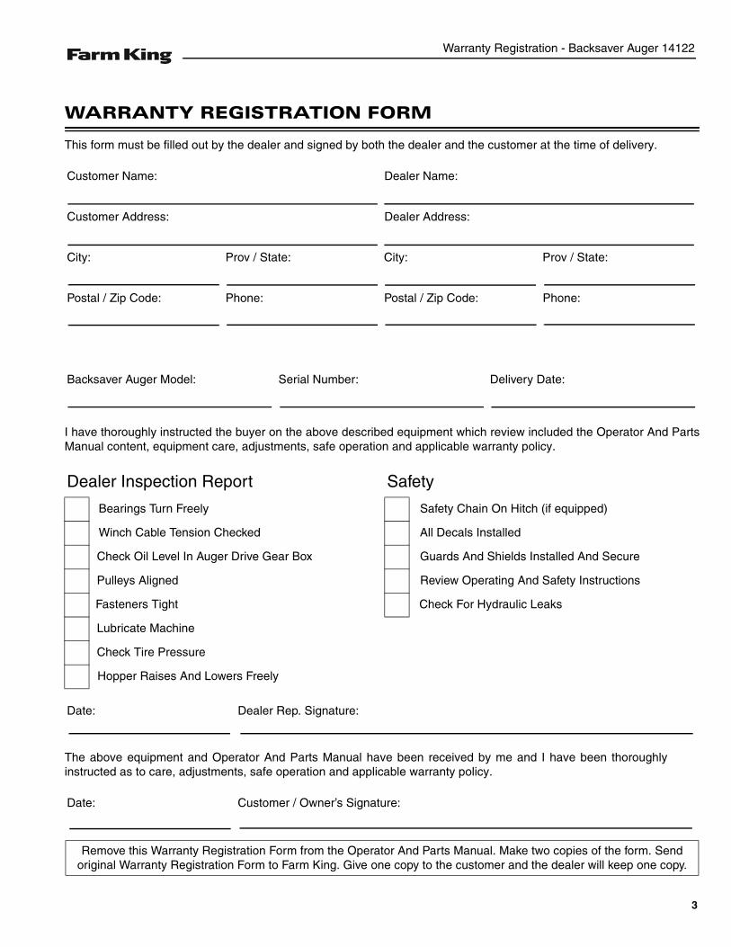
WARRANTY REGISTRATION FORM
This form must be filled out by the dealer and signed by both the dealer and the customer at the time of delivery.
I have thoroughly instructed the buyer on the above described equipment which review included the Operator And PartsManual content, equipment care, adjustments, safe operation and applicable warranty policy.
The above equipment and Operator And Parts Manual have been received by me and I have been thoroughlyinstructed as to care, adjustments, safe operation and applicable warranty policy.
Customer Name: Dealer Name:
Customer Address: Dealer Address:
City: Prov / State: City: Prov / State:
Postal / Zip Code: Phone: Postal / Zip Code: Phone:
Backsaver Auger Model: Serial Number: Delivery Date:
Dealer Inspection Report Safety
Bearings Turn Freely Safety Chain On Hitch (if equipped)
Winch Cable Tension Checked All Decals Installed
Check Oil Level In Auger Drive Gear Box Guards And Shields Installed And Secure
Pulleys Aligned Review Operating And Safety Instructions
Fasteners Tight Check For Hydraulic Leaks
Lubricate Machine
Check Tire Pressure
Hopper Raises And Lowers Freely
Date: Dealer Rep. Signature:
Date: Customer / Owner’s Signature:
Remove this Warranty Registration Form from the Operator And Parts Manual. Make two copies of the form. Send original Warranty Registration Form to Farm King. Give one copy to the customer and the dealer will keep one copy.
3

Warranty Registration - Backsaver Auger 14122
4
Introduction - Backsaver Auger 14122
INTRODUCTION
This Operator And Parts Manual was written to give the owner / operator instructions on the safe operation, maintenanceand part identification of the Farm King equipment. READ AND UNDERSTAND THIS OPERATOR AND PARTS MANUALBEFORE OPERATING YOUR FARM KING EQUIPMENT. If you have any questions, see your Farm King dealer. Thismanual may illustrate options and accessories not installed on your Farm King equipment.
OWNER’S INFORMATION . . . . . . . . . . . . . . . . . . . . . . . . . . . . . . . . . . . . . . . . . . . . . . . . . . . . . . . . . 7Serial Number Location . . . . . . . . . . . . . . . . . . . . . . . . . . . . . . . . . . . . . . . . . . . . . . . . . . . . . . . . 7Manual Storage . . . . . . . . . . . . . . . . . . . . . . . . . . . . . . . . . . . . . . . . . . . . . . . . . . . . . . . . . . . . . . . 7
EQUIPMENT IDENTIFICATION . . . . . . . . . . . . . . . . . . . . . . . . . . . . . . . . . . . . . . . . . . . . . . . . . . . . . 8Component Location . . . . . . . . . . . . . . . . . . . . . . . . . . . . . . . . . . . . . . . . . . . . . . . . . . . . . . . . . . . 8
5

Introduction - Backsaver Auger 14122
6
Introduction - Backsaver Auger 14122
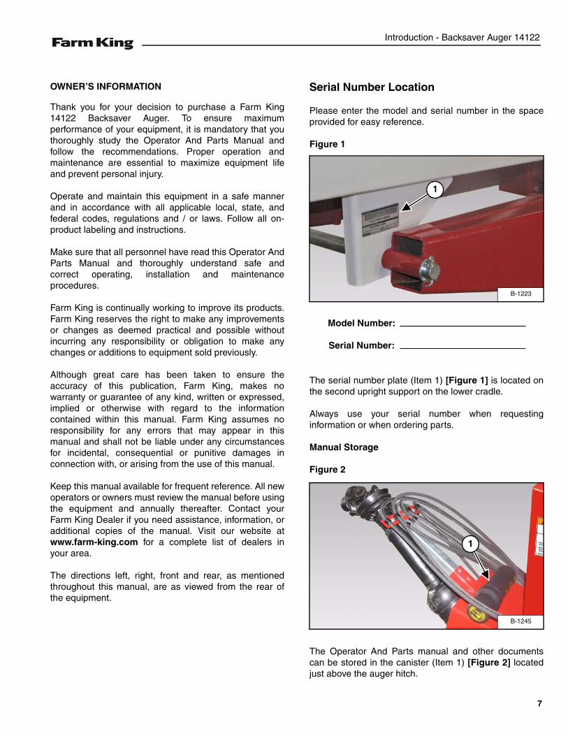
OWNER’S INFORMATION
Thank you for your decision to purchase a Farm King14122 Backsaver Auger. To ensure maximumperformance of your equipment, it is mandatory that youthoroughly study the Operator And Parts Manual andfollow the recommendations. Proper operation andmaintenance are essential to maximize equipment lifeand prevent personal injury.
Operate and maintain this equipment in a safe mannerand in accordance with all applicable local, state, andfederal codes, regulations and / or laws. Follow all on-product labeling and instructions.
Make sure that all personnel have read this Operator AndParts Manual and thoroughly understand safe andcorrect operating, installation and maintenanceprocedures.
Farm King is continually working to improve its products.Farm King reserves the right to make any improvementsor changes as deemed practical and possible withoutincurring any responsibility or obligation to make anychanges or additions to equipment sold previously.
Although great care has been taken to ensure theaccuracy of this publication, Farm King, makes nowarranty or guarantee of any kind, written or expressed,implied or otherwise with regard to the informationcontained within this manual. Farm King assumes noresponsibility for any errors that may appear in thismanual and shall not be liable under any circumstancesfor incidental, consequential or punitive damages inconnection with, or arising from the use of this manual.
Keep this manual available for frequent reference. All newoperators or owners must review the manual before usingthe equipment and annually thereafter. Contact yourFarm King Dealer if you need assistance, information, oradditional copies of the manual. Visit our website atwww.farm-king.com for a complete list of dealers inyour area.
The directions left, right, front and rear, as mentionedthroughout this manual, are as viewed from the rear ofthe equipment.
Serial Number Location
Please enter the model and serial number in the spaceprovided for easy reference.
Figure 1
The serial number plate (Item 1) [Figure 1] is located onthe second upright support on the lower cradle.
Always use your serial number when requestinginformation or when ordering parts.
Manual Storage
Figure 2
The Operator And Parts manual and other documentscan be stored in the canister (Item 1) [Figure 2] locatedjust above the auger hitch.
B-1223
1
Model Number:
Serial Number:
B-1245
1
7
Introduction - Backsaver Auger 14122
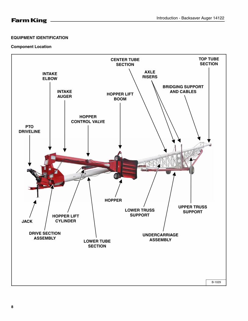
EQUIPMENT IDENTIFICATION
Component Location
B-1029
AXLE RISERS
LOWER TRUSS SUPPORT
UPPER TRUSS SUPPORT
JACK
DRIVE SECTION ASSEMBLY
HOPPER LIFT CYLINDER
HOPPER LIFT BOOM
UNDERCARRIAGE ASSEMBLY
HOPPER
TOP TUBE SECTION
BRIDGING SUPPORT AND CABLES
CENTER TUBE SECTION
HOPPER CONTROL VALVE
INTAKE AUGER
INTAKE ELBOW
PTO DRIVELINE
LOWER TUBE SECTION
8
Safety - Backsaver Auger 14122
SAFETY
SAFETY INSTRUCTIONS . . . . . . . . . . . . . . . . . . . . . . . . . . . . . . . . . . . . . . . . . . . . . . . . . . . . . . . . 11Safe Operation Is The Operator’s Responsibility . . . . . . . . . . . . . . . . . . . . . . . . . . . . . . . . . . . . 11Safe Operation Needs A Qualified Operator . . . . . . . . . . . . . . . . . . . . . . . . . . . . . . . . . . . . . . . . 11Use Safety Rules . . . . . . . . . . . . . . . . . . . . . . . . . . . . . . . . . . . . . . . . . . . . . . . . . . . . . . . . . . . . 12Transport Safety . . . . . . . . . . . . . . . . . . . . . . . . . . . . . . . . . . . . . . . . . . . . . . . . . . . . . . . . . . . . . 12Safety Rules For Power Take-Off (PTO) Driven Equipment . . . . . . . . . . . . . . . . . . . . . . . . . . . .13Machine Requirements And Capabilities . . . . . . . . . . . . . . . . . . . . . . . . . . . . . . . . . . . . . . . . . .13
FIRE PREVENTION . . . . . . . . . . . . . . . . . . . . . . . . . . . . . . . . . . . . . . . . . . . . . . . . . . . . . . . . . . . . . 14Maintenance . . . . . . . . . . . . . . . . . . . . . . . . . . . . . . . . . . . . . . . . . . . . . . . . . . . . . . . . . . . . . . . . 14Operation . . . . . . . . . . . . . . . . . . . . . . . . . . . . . . . . . . . . . . . . . . . . . . . . . . . . . . . . . . . . . . . . . . 14Starting . . . . . . . . . . . . . . . . . . . . . . . . . . . . . . . . . . . . . . . . . . . . . . . . . . . . . . . . . . . . . . . . . . . . 14Electrical . . . . . . . . . . . . . . . . . . . . . . . . . . . . . . . . . . . . . . . . . . . . . . . . . . . . . . . . . . . . . . . . . . . 14Hydraulic System . . . . . . . . . . . . . . . . . . . . . . . . . . . . . . . . . . . . . . . . . . . . . . . . . . . . . . . . . . . . 14Fueling . . . . . . . . . . . . . . . . . . . . . . . . . . . . . . . . . . . . . . . . . . . . . . . . . . . . . . . . . . . . . . . . . . . . 14Spark Arrester Exhaust System . . . . . . . . . . . . . . . . . . . . . . . . . . . . . . . . . . . . . . . . . . . . . . . . .14Welding And Grinding . . . . . . . . . . . . . . . . . . . . . . . . . . . . . . . . . . . . . . . . . . . . . . . . . . . . . . . . . 15Fire Extinguishers . . . . . . . . . . . . . . . . . . . . . . . . . . . . . . . . . . . . . . . . . . . . . . . . . . . . . . . . . . . .15
OPERATING SAFETY ZONE . . . . . . . . . . . . . . . . . . . . . . . . . . . . . . . . . . . . . . . . . . . . . . . . . . . . . . 16Safety Zone Identification . . . . . . . . . . . . . . . . . . . . . . . . . . . . . . . . . . . . . . . . . . . . . . . . . . . . . . 16
SAFETY SIGNS (DECALS) . . . . . . . . . . . . . . . . . . . . . . . . . . . . . . . . . . . . . . . . . . . . . . . . . . . . . . . 17
EQUIPMENT DECALS AND SIGNS . . . . . . . . . . . . . . . . . . . . . . . . . . . . . . . . . . . . . . . . . . . . . . . . 24
SAFETY SIGN-OFF FORM . . . . . . . . . . . . . . . . . . . . . . . . . . . . . . . . . . . . . . . . . . . . . . . . . . . . . . . 26
9

Safety - Backsaver Auger 14122
10
Safety - Backsaver Auger 14122
SAFETY INSTRUCTIONS
Safe Operation Is The Operator’s Responsibility
Safe Operation Needs A Qualified Operator
For an operator to be qualified, he or she must not usedrugs or alcoholic drinks which impair alertness orcoordination while working. An operator who is takingprescription drugs must get medical advice to determineif he or she can safely operate a machine and theequipment.
A Qualified Operator Must Do The Following:
Understand the Written Instructions, Rules andRegulations
• The written instructions from Farm King include theWarranty Registration, Dealer Inspection Report,Operator And Parts Manual and machine signs(decals).
• Check the rules and regulations at your location. Therules may include an employer’s work safetyrequirements. Regulations may apply to local drivingrequirements or use of a Slow Moving Vehicle (SMV)emblem. Regulations may identify a hazard such as autility line.
Have Training with Actual Operation
• Operator training must consist of a demonstration andverbal instruction. This training is given by themachine owner prior to operation.
• The new operator must start in an area withoutbystanders and use all the controls until he or she canoperate the machine safely under all conditions of thework area. Always fasten seat belt before operating.
Know the Work Conditions
• Clear working area of all bystanders, especially smallchildren and all obstacles that might be hooked orsnagged, causing injury or damage.
• Know the location of any overhead or undergroundpower lines. Call local utilities and have allunderground power lines marked prior to operation.
• Wear tight fitting clothing. Always wear safety glasseswhen doing maintenance or service.
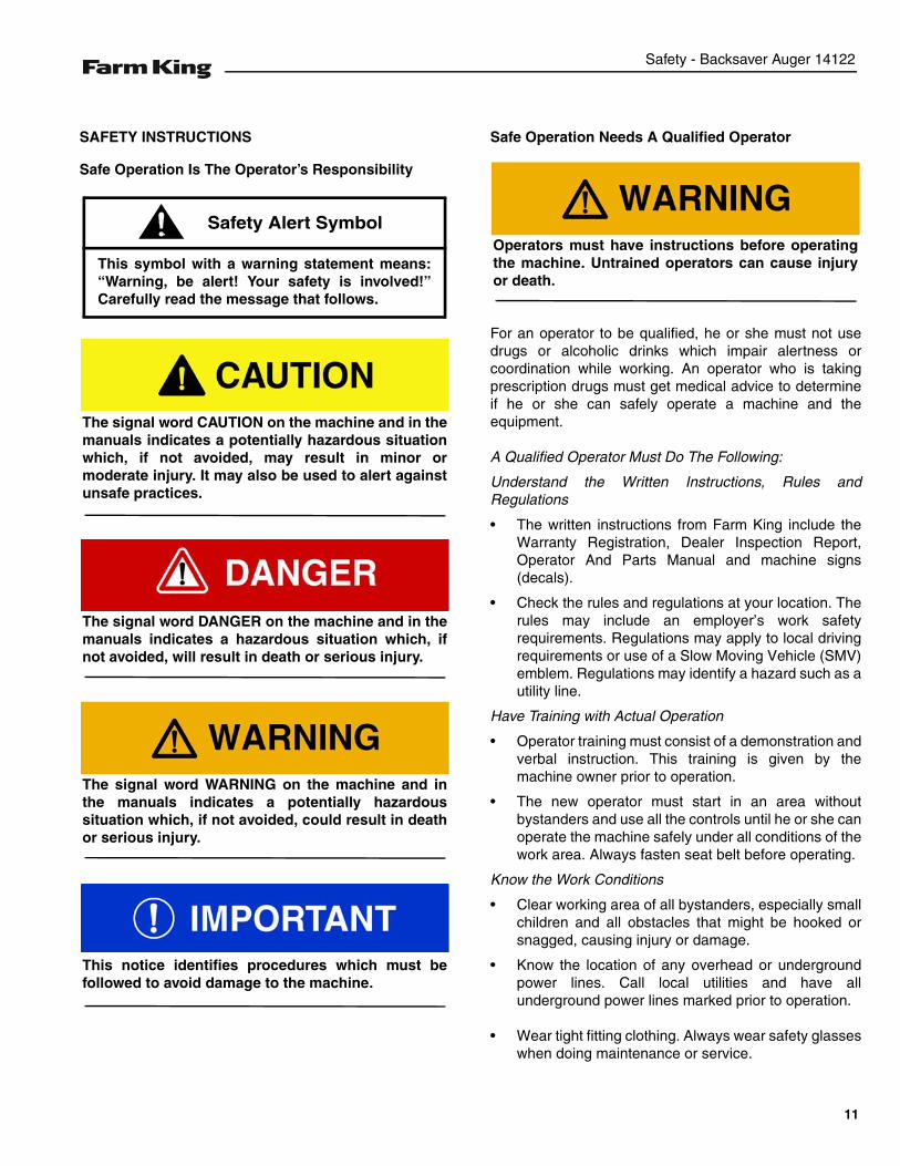
This symbol with a warning statement means:“Warning, be alert! Your safety is involved!”Carefully read the message that follows.
Safety Alert Symbol
The signal word CAUTION on the machine and in themanuals indicates a potentially hazardous situationwhich, if not avoided, may result in minor ormoderate injury. It may also be used to alert againstunsafe practices.
The signal word DANGER on the machine and in themanuals indicates a hazardous situation which, ifnot avoided, will result in death or serious injury.
The signal word WARNING on the machine and inthe manuals indicates a potentially hazardoussituation which, if not avoided, could result in deathor serious injury.
This notice identifies procedures which must befollowed to avoid damage to the machine.
Operators must have instructions before operatingthe machine. Untrained operators can cause injuryor death.
11
Safety - Backsaver Auger 14122
SAFETY INSTRUCTIONS (CONT’D)
Use Safety Rules
• Read and follow instructions in this manual and thetractor’s Operators Manual before operating.
• Under no circumstances should young children beallowed to work with this equipment.
• This equipment is dangerous to children and personsunfamiliar with its operation.
• If the elderly are assisting with work, their physicallimitations need to be recognized andaccommodated.
• Stay clear of overhead power lines when unloadingauger is extended. Electrocution can occur withoutdirect contact.
• Check for overhead and / or underground lines beforeoperating equipment (if applicable).
• In addition to the design and configuration ofequipment, hazard control and accident preventionare dependent upon the awareness, concern,prudence and proper training of personnel involved inthe operation, transport, maintenance and storage ofequipment.
• Check that the equipment is securely fastened to thetractor / towing vehicle.
• Make sure all the machine controls are in theNEUTRAL position before starting the machine.
• Operate the equipment only from the operator’sposition.
• Operate the equipment according to the OperatorAnd Parts Manual.
• When learning to operate the equipment, do it at aslow rate in an area clear of bystanders, especiallysmall children.
• DO NOT permit personnel to be in the work areawhen operating the equipment.
• The equipment must be used ONLY on approvedtractors / transport vehicles.
• DO NOT modify the equipment in any way.Unauthorized modification may impair the functionand / or safety and could affect the life of theequipment.
• DO NOT make any adjustments or repairs on theequipment while the machine is running.
• Keep shields and guards in place. Replace ifdamaged.
Transport Safety
• Do not exceed 20 mph (32 kph). Reduce speed onrough roads and surfaces.
• Comply with state and local laws governing highwaysafety and movement of machinery on public roads.
• The use of flashing amber lights is acceptable in mostlocalities. However, some localities prohibit their use.Local laws should be checked for all highway lightingand marking requirements.
• Always install transport locks, pins or brackets beforetransporting.
• Always yield to oncoming traffic in all situations andmove to the side of the road so any following trafficmay pass.
• Always enter curves or drive up or down hills at a lowspeed and at a gradual steering angle.
• Never allow riders on either tractor or equipment.
• Keep tractor / towing vehicle in a lower gear at alltimes when traveling down steep grades.
• Maintain proper brake settings at all times (ifequipped).
• Stay away from overhead power lines whenunloading auger is extended. Electrocution can occurwithout direct contact.
12
Safety - Backsaver Auger 14122
Safety Rules For Power Take-Off (PTO) Driven Equipment
• Keep PTO shields and all guards in place. Replacedamaged or missing shields and guards beforeoperating.
• Follow warnings and instructions on machine signs(decals). Replace damaged or missing decals.
• Do not wear loose or bulky clothing around the PTOor other moving parts.
• Keep bystanders away from PTO driven equipment,and never allow children near machines.
• Read and understand the manuals for the PTO drivenequipment and be aware of safe operatingprocedures and hazards that may not be readilyapparent.
• Always walk around equipment to avoid coming neara turning PTO driveline. Stepping over, leaningacross or crawling under a turning PTO driveling cancause entanglement.
• Position the machine and equipment hitch correctly toprevent driveline stress and separation.
• Use caution when turning. Turning too sharp cancause driveline damage.
• Use caution when raising PTO driven attachment.Excessive driveline angle can cause drivelinedamage. Use stops if needed.
Machine Requirements And Capabilities
• Fasten seat belt securely. If equipped with a foldableRoll-Over Protective Structure (ROPS), only fastenseat belt when ROPS is up and locked. DO NOT wearseat belt if ROPS is down.
• Machine’s three-point hitch must be equipped withsway bars or chains.
• Stop the machine and engage the parking brake.Install blocks in front of and behind the rear tires of themachine. Install blocks underneath and support theequipment securely before working under raisedequipment.
• Keep bystanders clear of moving parts and the workarea. Keep children away.
• Use increased caution on slopes and near banks andditches to prevent overturn.
• Make certain that the Slow Moving Vehicle (SMV)emblem is installed so that it is visible and legible.When transporting the equipment, use the flashingwarning lights (if equipped) and follow all localregulations.
• Operate this equipment with a machine equipped withan approved Roll-Over Protective Structure (ROPS).Always wear seat belt when the ROPS is up. Seriousinjury or death could result from falling off themachine.
• Before leaving the operator’s position:
1. Always park on a flat level surface.2. Place all controls in neutral.3. Engage the parking brake.4. Stop engine.5. Wait for all moving parts to stop.
• Carry passengers only in designated seating areas.Never allow riders on the machine or equipment.Falling off can result in serious injury or death.
• Start the equipment only when properly seated in theoperator’s seat. Starting a machine in gear can resultin serious injury or death.
• Operate the machine and equipment from theoperator's position only.
• The parking brake must be engaged before leavingthe operator’s seat. Rollaway can occur because thetransmission may not prevent machine movement.
13
Safety - Backsaver Auger 14122
FIRE PREVENTION
Maintenance
The machine and some equipment have componentsthat are at high temperatures under normal operatingconditions. The primary source of high temperatures isthe engine and exhaust system. The electrical system, ifdamaged or incorrectly maintained, can be a source ofarcs or sparks.
Flammable debris (leaves, straw, etc.) must be removedregularly. If flammable debris is allowed to accumulate, itcan cause a fire hazard. Clean often to avoid thisaccumulation. Flammable debris in the enginecompartment is a potential fire hazard.
The operator’s area, engine compartment and enginecooling system must be inspected every day and cleanedif necessary to prevent fire hazards and overheating.
All fuels, most lubricants and some coolant mixtures areflammable. Flammable fluids that are leaking or spilledonto hot surfaces or onto electrical components cancause a fire.
Operation
The Farm King machine must be in good operatingcondition before use.
Check all of the items listed on the service scheduleunder the 8 hour column. (See “SERVICE SCHEDULE”on page 108.)
Do not use the machine where exhaust, arcs, sparks orhot components can contact flammable material,explosive dust or gases.
Starting
Do not use ether or starting fluids on any engine that hasglow plugs. These starting aids can cause explosion andinjure you or bystanders.
Use the procedure in the tractor’s operator’s manual forconnecting the battery and for jump starting.
Electrical
Check all electrical wiring and connections for damage.Keep the battery terminals clean and tight. Repair orreplace any damaged part or wires that are loose orfrayed.
Battery gas can explode and cause serious injury. Do notjump start or charge a frozen or damaged battery. Keepany open flames or sparks away from batteries. Do notsmoke in battery charging area.
Hydraulic System
Check hydraulic tubes, hoses and fittings for damageand leakage. Never use open flame or bare skin to checkfor leaks. Hydraulic tubes and hoses must be properlyrouted and have adequate support and secure clamps.Tighten or replace any parts that show leakage.
Always clean fluid spills. Do not use gasoline or dieselfuel for cleaning parts. Use commercial nonflammablesolvents.
Fueling
Stop the engine and let it cool before adding fuel. Nosmoking! Do not refuel a machine near open flames orsparks. Fill the fuel tank outdoors.
Spark Arrester Exhaust System
The spark arrester exhaust system is designed to controlthe emission of hot particles from the engine and exhaustsystem, but the muffler and the exhaust gases are stillhot.
Check the spark arrester exhaust system regularly tomake sure it is maintained and working properly. Use theprocedure in the machine’s Operator’s Manual forcleaning the spark arrester muffler (if equipped).
14
Safety - Backsaver Auger 14122
FIRE PREVENTION (CONT’D)
Welding And Grinding
Always clean the machine and equipment, disconnectthe battery, and disconnect the wiring from the machinecontrols before welding. Cover rubber hoses, battery andall other flammable parts. Keep a fire extinguisher nearthe machine when welding.
Have good ventilation when grinding or welding paintedparts. Wear dust mask when grinding painted parts.Toxic dust or gas can be produced.
Dust generated from repairing nonmetallic parts such ashoods, fenders or covers can be flammable or explosive.Repair such components in a well ventilated area awayfrom open flames or sparks.
Fire Extinguishers
Know where fire extinguishers and first aid kits arelocated and how to use them. Inspect the fireextinguisher and service the fire extinguisher regularly.Obey the recommendations on the instructions plate.
15
Safety - Backsaver Auger 14122
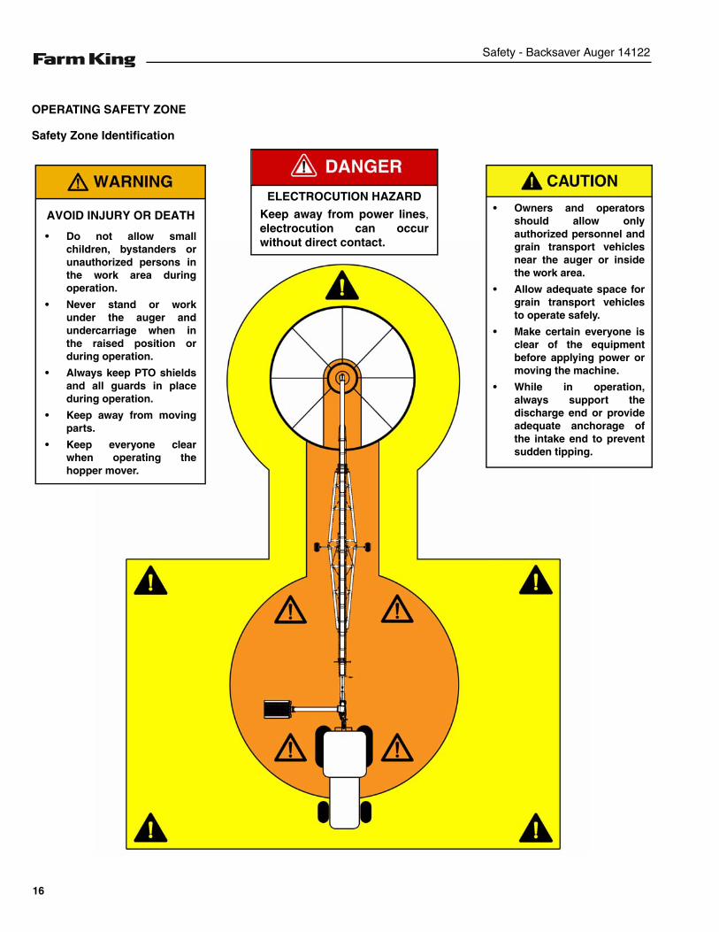
OPERATING SAFETY ZONE
Safety Zone Identification
AVOID INJURY OR DEATH
• Do not allow smallchildren, bystanders orunauthorized persons inthe work area duringoperation.
• Never stand or workunder the auger andundercarriage when inthe raised position orduring operation.
• Always keep PTO shieldsand all guards in placeduring operation.
• Keep away from movingparts.
• Keep everyone clearwhen operating thehopper mover.
• Owners and operatorsshould allow onlyauthorized personnel andgrain transport vehiclesnear the auger or insidethe work area.
• Allow adequate space forgrain transport vehiclesto operate safely.
• Make certain everyone isclear of the equipmentbefore applying power ormoving the machine.
• While in operation,always support thedischarge end or provideadequate anchorage ofthe intake end to preventsudden tipping.
ELECTROCUTION HAZARD
Keep away from power lines,electrocution can occurwithout direct contact.
16
Safety - Backsaver Auger 14122
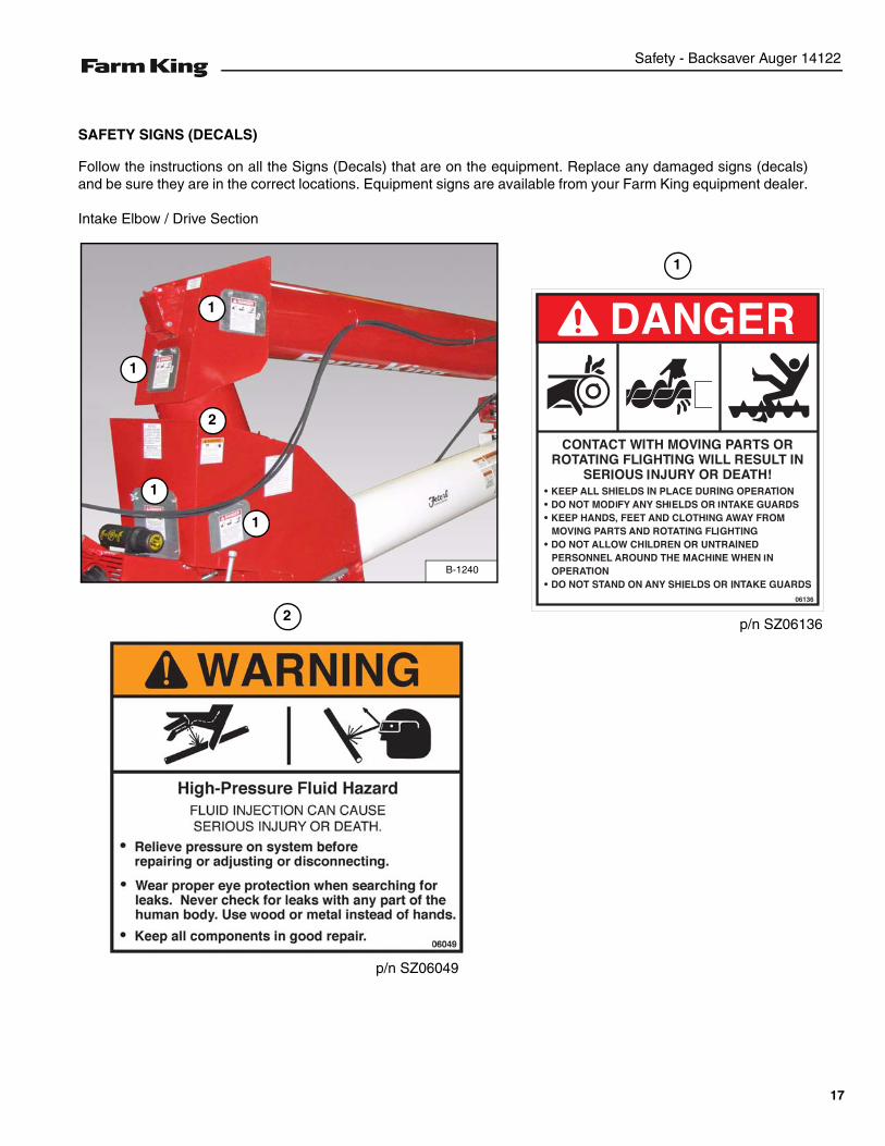
SAFETY SIGNS (DECALS)
Follow the instructions on all the Signs (Decals) that are on the equipment. Replace any damaged signs (decals)and be sure they are in the correct locations. Equipment signs are available from your Farm King equipment dealer.
Intake Elbow / Drive Section
1
2
p/n SZ06049
p/n SZ06136
B-1240
1
2
1
1
1
17
Safety - Backsaver Auger 14122
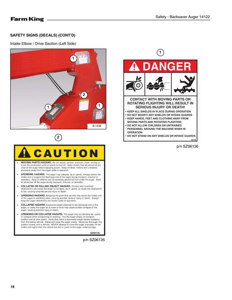
SAFETY SIGNS (DECALS) (CONT’D)
Intake Elbow / Drive Section (Left Side)
B-1238
1
1 1
2
2
p/n SZ06135
1
p/n SZ06136
18
Safety - Backsaver Auger 14122
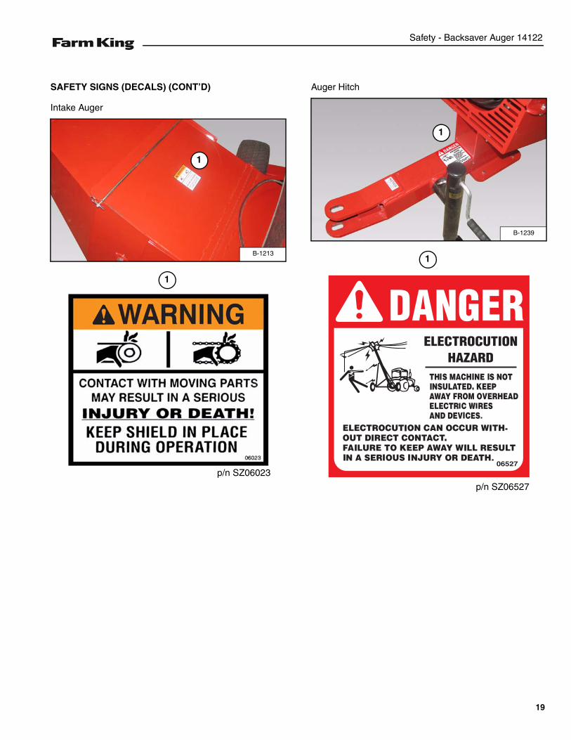
SAFETY SIGNS (DECALS) (CONT’D)
Intake Auger
Auger Hitch
B-1213
1
1
p/n SZ06023
B-1239
1
1
p/n SZ06527
19
Safety - Backsaver Auger 14122
SAFETY SIGNS (DECALS) (CONT’D)
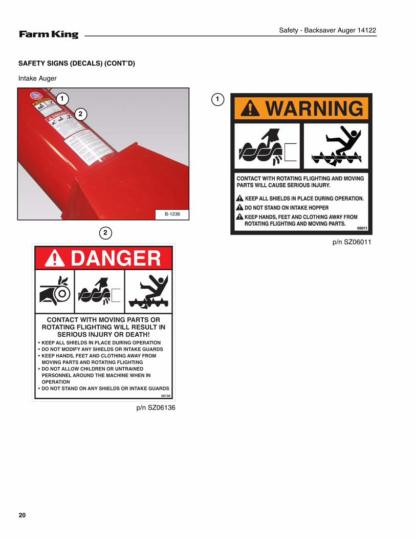
Intake Auger
B-1236
1
2
1
p/n SZ06136
p/n SZ060112
20
Safety - Backsaver Auger 14122
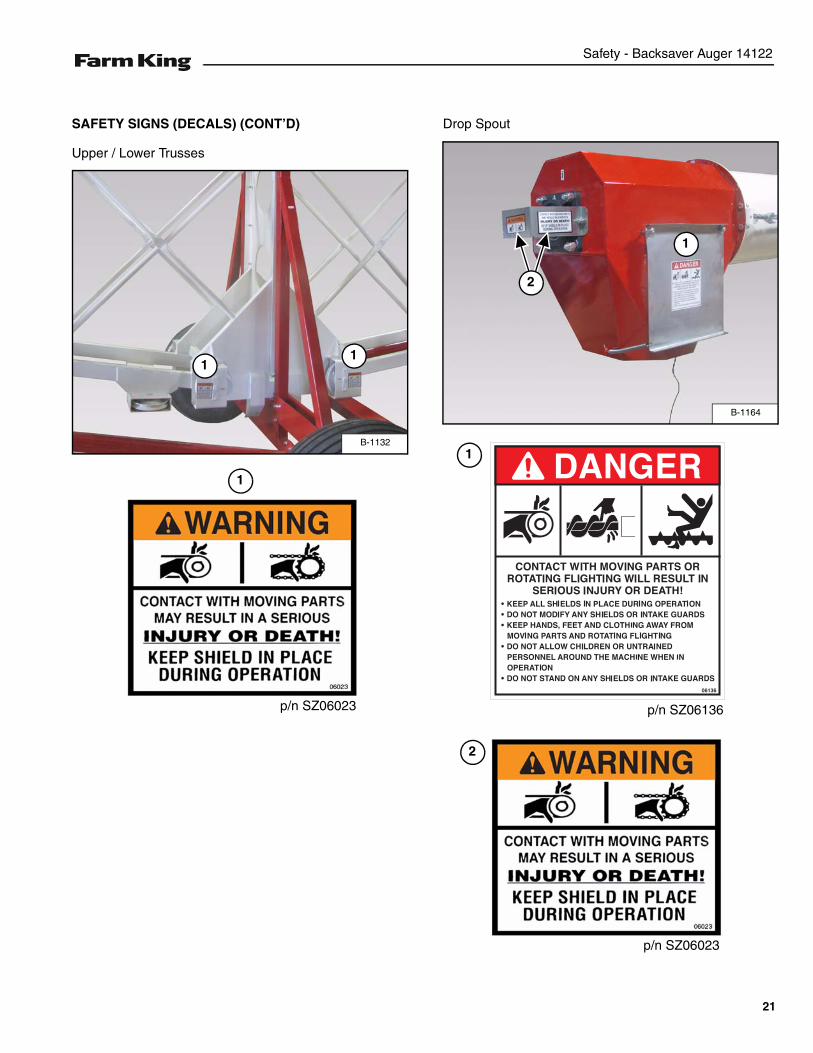
SAFETY SIGNS (DECALS) (CONT’D)
Upper / Lower Trusses
Drop Spout
B-1132
11
p/n SZ06023
1
B-1164
1
2
1
p/n SZ06136
p/n SZ06023
2
21
Safety - Backsaver Auger 14122
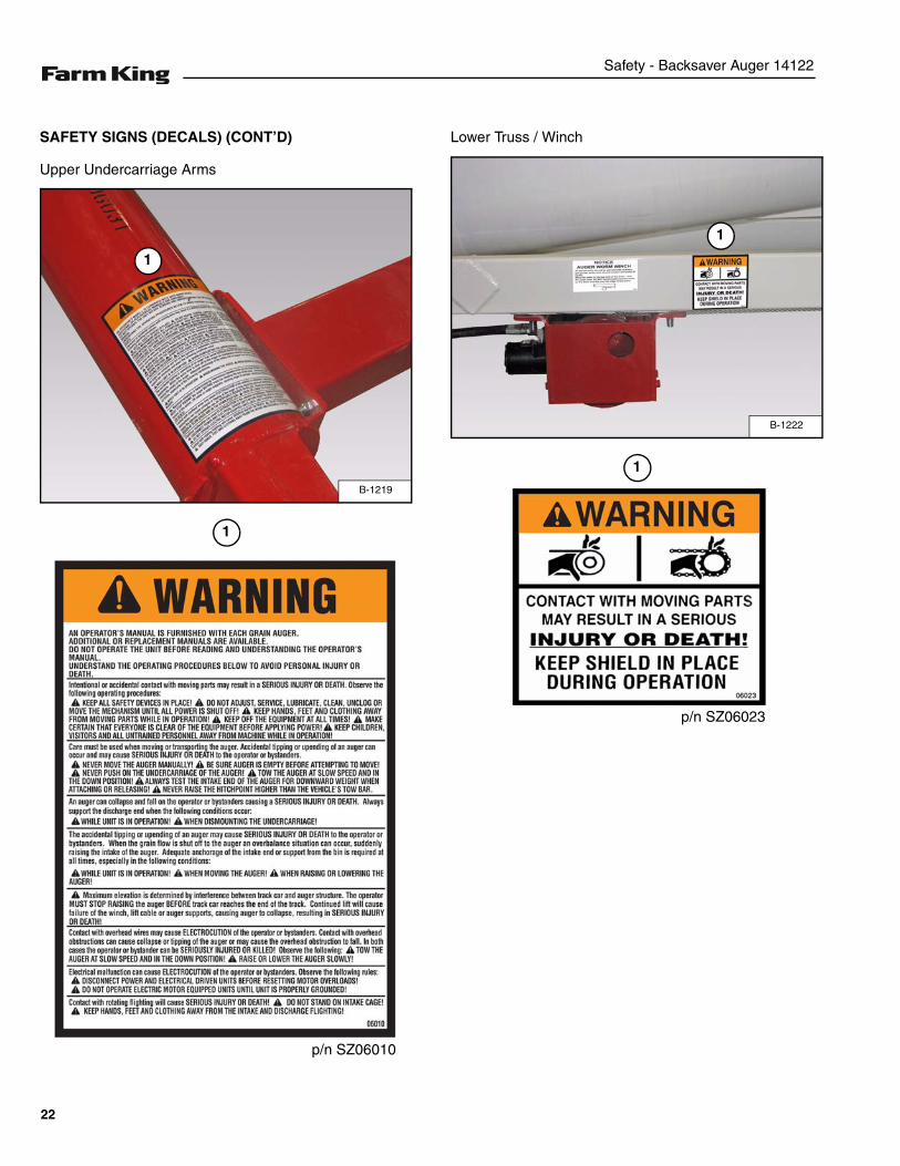
SAFETY SIGNS (DECALS) (CONT’D)
Upper Undercarriage Arms
Lower Truss / Winch
B-1219
1
p/n SZ06010
1
B-1222
1
p/n SZ06023
1
22
Safety - Backsaver Auger 14122
SAFETY SIGNS (DECALS) (CONT’D)
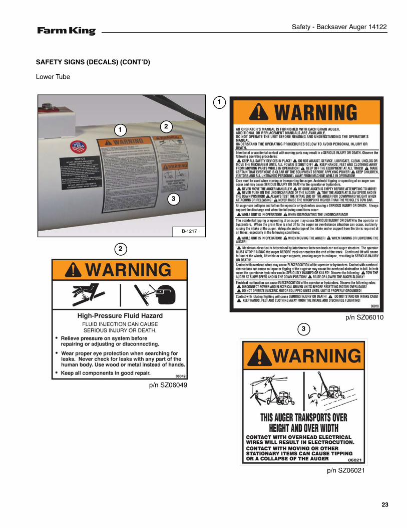
Lower Tube
B-1217
1 2
3
p/n SZ06010
1
p/n SZ06021
p/n SZ06049
2
3
23
Safety - Backsaver Auger 14122
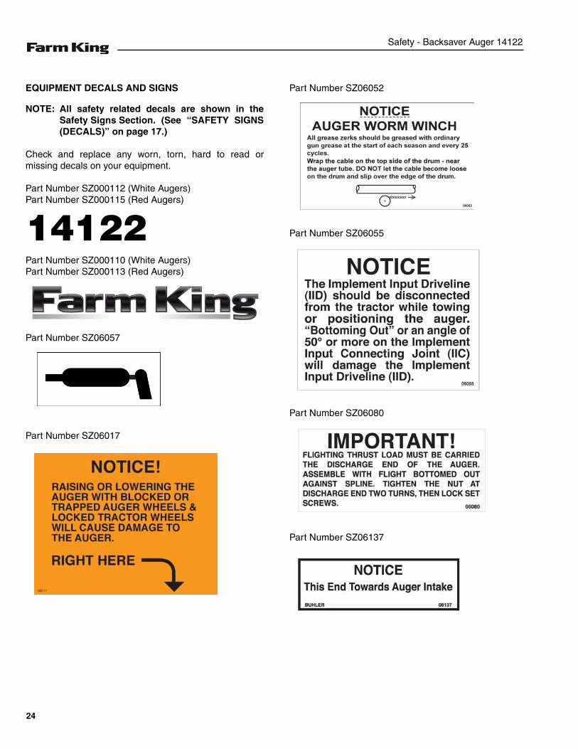
EQUIPMENT DECALS AND SIGNS
NOTE: All safety related decals are shown in theSafety Signs Section. (See “SAFETY SIGNS(DECALS)” on page 17.)
Check and replace any worn, torn, hard to read ormissing decals on your equipment.
Part Number SZ000112 (White Augers)Part Number SZ000115 (Red Augers)
Part Number SZ000110 (White Augers)Part Number SZ000113 (Red Augers)
Part Number SZ06057
Part Number SZ06017
Part Number SZ06052
Part Number SZ06055
Part Number SZ06080
Part Number SZ06137
14122
24
Safety - Backsaver Auger 14122
EQUIPMENT DECALS AND SIGNS (CONT’D)
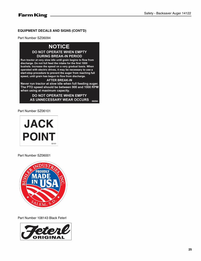
Part Number SZ06094
Part Number SZ06101
Part Number SZ06001
Part Number 108143 Black Feterl
25
Safety - Backsaver Auger 14122
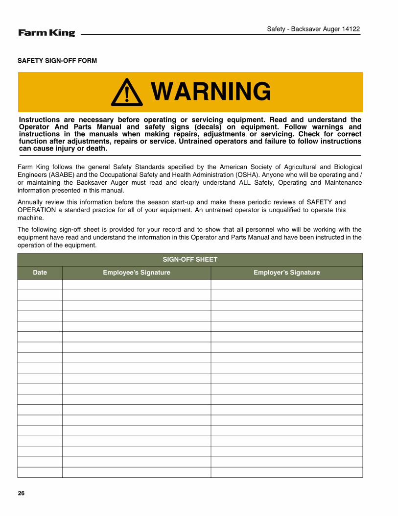
SAFETY SIGN-OFF FORM
Farm King follows the general Safety Standards specified by the American Society of Agricultural and BiologicalEngineers (ASABE) and the Occupational Safety and Health Administration (OSHA). Anyone who will be operating and /or maintaining the Backsaver Auger must read and clearly understand ALL Safety, Operating and Maintenanceinformation presented in this manual.
Annually review this information before the season start-up and make these periodic reviews of SAFETY andOPERATION a standard practice for all of your equipment. An untrained operator is unqualified to operate thismachine.
The following sign-off sheet is provided for your record and to show that all personnel who will be working with theequipment have read and understand the information in this Operator and Parts Manual and have been instructed in theoperation of the equipment.
SIGN-OFF SHEET
Date Employee’s Signature Employer’s Signature
Instructions are necessary before operating or servicing equipment. Read and understand theOperator And Parts Manual and safety signs (decals) on equipment. Follow warnings andinstructions in the manuals when making repairs, adjustments or servicing. Check for correctfunction after adjustments, repairs or service. Untrained operators and failure to follow instructionscan cause injury or death.
26
Assembly - Backsaver Auger 14122
ASSEMBLY
GENERAL ASSEMBLY INFORMATION . . . . . . . . . . . . . . . . . . . . . . . . . . . . . . . . . . . . . . . . . . . . . 29Component Unloading And Identification . . . . . . . . . . . . . . . . . . . . . . . . . . . . . . . . . . . . . . . . . .29
BASE GROUP . . . . . . . . . . . . . . . . . . . . . . . . . . . . . . . . . . . . . . . . . . . . . . . . . . . . . . . . . . . . . . . . . 30Undercarriage Assembly . . . . . . . . . . . . . . . . . . . . . . . . . . . . . . . . . . . . . . . . . . . . . . . . . . . . . . . 30Tube Assembly . . . . . . . . . . . . . . . . . . . . . . . . . . . . . . . . . . . . . . . . . . . . . . . . . . . . . . . . . . . . . . 38Installing The Track Car . . . . . . . . . . . . . . . . . . . . . . . . . . . . . . . . . . . . . . . . . . . . . . . . . . . . . . . 53Installing The Axle Risers . . . . . . . . . . . . . . . . . . . . . . . . . . . . . . . . . . . . . . . . . . . . . . . . . . . . . . 54Installing The Top Tube Support Cables . . . . . . . . . . . . . . . . . . . . . . . . . . . . . . . . . . . . . . . . . . . 54Installing The STOP LIFT Sign . . . . . . . . . . . . . . . . . . . . . . . . . . . . . . . . . . . . . . . . . . . . . . . . . . 56Track Car / Winch Cable Routing . . . . . . . . . . . . . . . . . . . . . . . . . . . . . . . . . . . . . . . . . . . . . . . . 57Winch Assembly And Installation . . . . . . . . . . . . . . . . . . . . . . . . . . . . . . . . . . . . . . . . . . . . . . . . 58Installing The Hopper Telescoping Power Driveline . . . . . . . . . . . . . . . . . . . . . . . . . . . . . . . . . . 61Hopper Assembly And Installation . . . . . . . . . . . . . . . . . . . . . . . . . . . . . . . . . . . . . . . . . . . . . . . 62
HYDRAULIC ASSEMBLY . . . . . . . . . . . . . . . . . . . . . . . . . . . . . . . . . . . . . . . . . . . . . . . . . . . . . . . . . 65Winch Fitting And Hose Installation . . . . . . . . . . . . . . . . . . . . . . . . . . . . . . . . . . . . . . . . . . . . . . 65
WINCH CABLE INSTALLATION . . . . . . . . . . . . . . . . . . . . . . . . . . . . . . . . . . . . . . . . . . . . . . . . . . . . 69Cable Routing and Installation . . . . . . . . . . . . . . . . . . . . . . . . . . . . . . . . . . . . . . . . . . . . . . . . . . 69
27

Assembly - Backsaver Auger 14122
28
Assembly - Backsaver Auger 14122
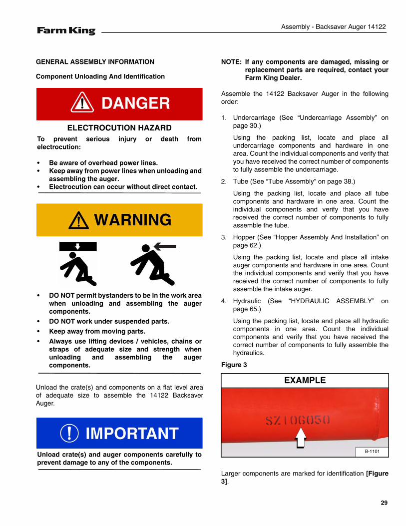
GENERAL ASSEMBLY INFORMATION
Component Unloading And Identification
Unload the crate(s) and components on a flat level areaof adequate size to assemble the 14122 BacksaverAuger.
NOTE: If any components are damaged, missing orreplacement parts are required, contact yourFarm King Dealer.
Assemble the 14122 Backsaver Auger in the followingorder:
1. Undercarriage (See “Undercarriage Assembly” onpage 30.)
Using the packing list, locate and place allundercarriage components and hardware in onearea. Count the individual components and verify thatyou have received the correct number of componentsto fully assemble the undercarriage.
2. Tube (See “Tube Assembly” on page 38.)
Using the packing list, locate and place all tubecomponents and hardware in one area. Count theindividual components and verify that you havereceived the correct number of components to fullyassemble the tube.
3. Hopper (See “Hopper Assembly And Installation” onpage 62.)
Using the packing list, locate and place all intakeauger components and hardware in one area. Countthe individual components and verify that you havereceived the correct number of components to fullyassemble the intake auger.
4. Hydraulic (See “HYDRAULIC ASSEMBLY” onpage 65.)
Using the packing list, locate and place all hydrauliccomponents in one area. Count the individualcomponents and verify that you have received thecorrect number of components to fully assemble thehydraulics.
Figure 3
Larger components are marked for identification [Figure3].
ELECTROCUTION HAZARDTo prevent serious injury or death fromelectrocution:
• Be aware of overhead power lines.• Keep away from power lines when unloading and
assembling the auger.• Electrocution can occur without direct contact.
• DO NOT permit bystanders to be in the work areawhen unloading and assembling the augercomponents.
• DO NOT work under suspended parts.
• Keep away from moving parts.
• Always use lifting devices / vehicles, chains orstraps of adequate size and strength whenunloading and assembling the augercomponents.
Unload crate(s) and auger components carefully toprevent damage to any of the components.
B-1101
EXAMPLE
29
Assembly - Backsaver Auger 14122
BASE GROUP
Undercarriage Assembly
Assemble the undercarriage on a flat level surface.
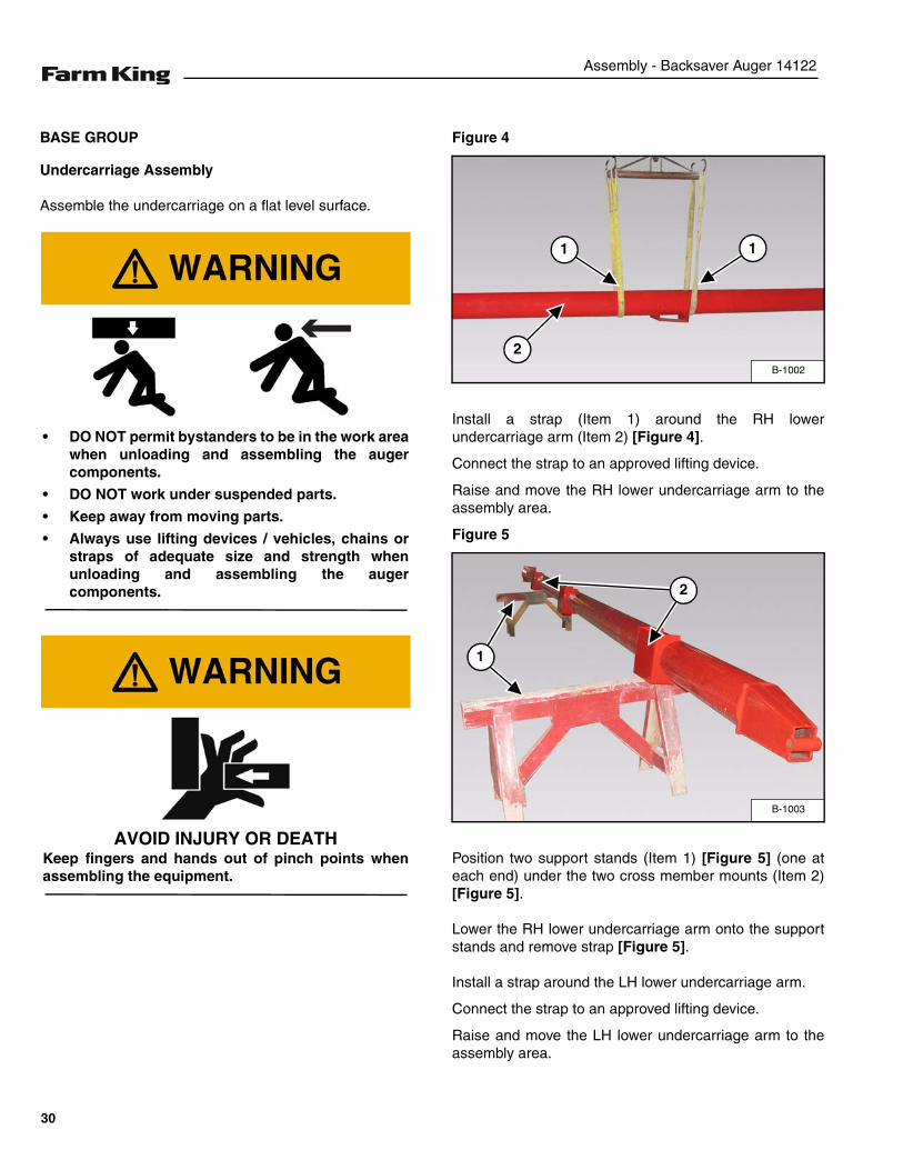
Figure 4
Install a strap (Item 1) around the RH lowerundercarriage arm (Item 2) [Figure 4].
Connect the strap to an approved lifting device.
Raise and move the RH lower undercarriage arm to theassembly area.
Figure 5
Position two support stands (Item 1) [Figure 5] (one ateach end) under the two cross member mounts (Item 2)[Figure 5].
Lower the RH lower undercarriage arm onto the supportstands and remove strap [Figure 5].
Install a strap around the LH lower undercarriage arm.
Connect the strap to an approved lifting device.
Raise and move the LH lower undercarriage arm to theassembly area.
• DO NOT permit bystanders to be in the work areawhen unloading and assembling the augercomponents.
• DO NOT work under suspended parts.
• Keep away from moving parts.
• Always use lifting devices / vehicles, chains orstraps of adequate size and strength whenunloading and assembling the augercomponents.
AVOID INJURY OR DEATHKeep fingers and hands out of pinch points whenassembling the equipment.
B-1002
1
2
1
B-1003
1
2
30
Assembly - Backsaver Auger 14122
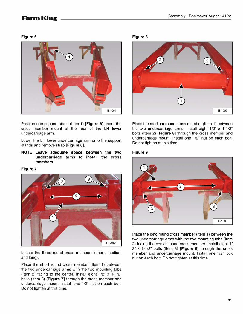
Figure 6
Position one support stand (Item 1) [Figure 6] under thecross member mount at the rear of the LH lowerundercarriage arm.
Lower the LH lower undercarriage arm onto the supportstands and remove strap [Figure 6].
NOTE: Leave adequate space between the twoundercarriage arms to install the crossmembers.
Figure 7
Locate the three round cross members (short, mediumand long).
Place the short round cross member (Item 1) betweenthe two undercarriage arms with the two mounting tabs(Item 2) facing to the center. Install eight 1/2” x 1-1/2”bolts (Item 3) [Figure 7] through the cross member andundercarriage mount. Install one 1/2” nut on each bolt.Do not tighten at this time.
Figure 8
Place the medium round cross member (Item 1) betweenthe two undercarriage arms. Install eight 1/2” x 1-1/2”bolts (Item 2) [Figure 8] through the cross member andundercarriage mount. Install one 1/2” nut on each bolt.Do not tighten at this time.
Figure 9
Place the long round cross member (Item 1) between thetwo undercarriage arms with the two mounting tabs (Item2) facing the center round cross member. Install eight 1/2” x 1-1/2” bolts (Item 3) [Figure 9] through the crossmember and undercarriage mount. Install one 1/2” locknut on each bolt. Do not tighten at this time.
B-1004
1
B-1006A
1
2
3 3
B-1007
1
22
B-1008
1
33
2
31
Assembly - Backsaver Auger 14122
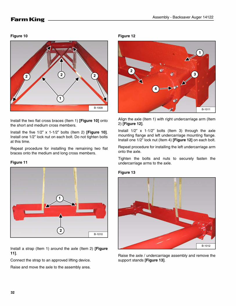
Figure 10
Install the two flat cross braces (Item 1) [Figure 10] ontothe short and medium cross members.
Install the five 1/2” x 1-1/2” bolts (Item 2) [Figure 10].Install one 1/2” lock nut on each bolt. Do not tighten boltsat this time.
Repeat procedure for installing the remaining two flatbraces onto the medium and long cross members.
Figure 11
Install a strap (Item 1) around the axle (Item 2) [Figure11].
Connect the strap to an approved lifting device.
Raise and move the axle to the assembly area.
Figure 12
Align the axle (Item 1) with right undercarriage arm (Item2) [Figure 12].
Install 1/2” x 1-1/2” bolts (Item 3) through the axlemounting flange and left undercarriage mounting flange.Install one 1/2” lock nut (Item 4) [Figure 12] on each bolt.
Repeat procedure for installing the left undercarriage armonto the axle.
Tighten the bolts and nuts to securely fasten theundercarriage arms to the axle.
Figure 13
Raise the axle / undercarriage assembly and remove thesupport stands [Figure 13].
B-1009
1
2 22
B-1010
1
2
B-1011
2
1
3
4
B-1012
32
Assembly - Backsaver Auger 14122
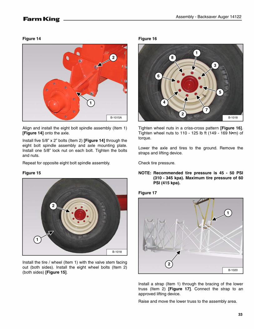
Figure 14
Align and install the eight bolt spindle assembly (Item 1)[Figure 14] onto the axle.
Install five 5/8” x 2” bolts (Item 2) [Figure 14] through theeight bolt spindle assembly and axle mounting plate.Install one 5/8” lock nut on each bolt. Tighten the boltsand nuts.
Repeat for opposite eight bolt spindle assembly.
Figure 15
Install the tire / wheel (Item 1) with the valve stem facingout (both sides). Install the eight wheel bolts (Item 2)(both sides) [Figure 15].
Figure 16
Tighten wheel nuts in a criss-cross pattern [Figure 16].Tighten wheel nuts to 110 - 125 lb ft (149 - 169 N•m) oftorque.
Lower the axle and tires to the ground. Remove thestraps and lifting device.
Check tire pressure.
NOTE: Recommended tire pressure is 45 - 50 PSI(310 - 345 kpa). Maximum tire pressure of 60PSI (415 kpa).
Figure 17
Install a strap (Item 1) through the bracing of the lowertruss (Item 2) [Figure 17]. Connect the strap to anapproved lifting device.
Raise and move the lower truss to the assembly area.
B-1015A
1
2
B-1018
1
2
B-1018
1
2
3
4
5
6
7
8
B-1020
2
1
33
Assembly - Backsaver Auger 14122
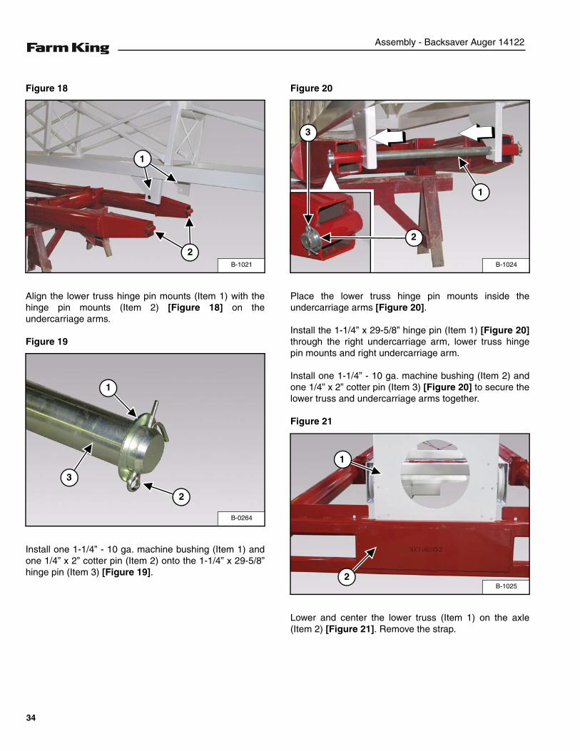
Figure 18
Align the lower truss hinge pin mounts (Item 1) with thehinge pin mounts (Item 2) [Figure 18] on theundercarriage arms.
Figure 19
Install one 1-1/4” - 10 ga. machine bushing (Item 1) andone 1/4” x 2” cotter pin (Item 2) onto the 1-1/4” x 29-5/8”hinge pin (Item 3) [Figure 19].
Figure 20
Place the lower truss hinge pin mounts inside theundercarriage arms [Figure 20].
Install the 1-1/4” x 29-5/8” hinge pin (Item 1) [Figure 20]through the right undercarriage arm, lower truss hingepin mounts and right undercarriage arm.
Install one 1-1/4” - 10 ga. machine bushing (Item 2) andone 1/4” x 2” cotter pin (Item 3) [Figure 20] to secure thelower truss and undercarriage arms together.
Figure 21
Lower and center the lower truss (Item 1) on the axle(Item 2) [Figure 21]. Remove the strap.
B-1021
1
2
B-0264
3
1
2
B-1024
1
3
2
B-1025
1
2
34
Assembly - Backsaver Auger 14122
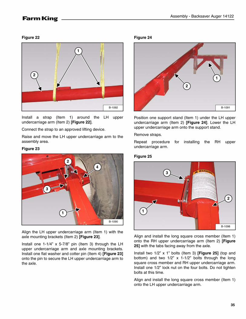
Figure 22
Install a strap (Item 1) around the LH upperundercarriage arm (Item 2) [Figure 22].
Connect the strap to an approved lifting device.
Raise and move the LH upper undercarriage arm to theassembly area.
Figure 23
Align the LH upper undercarriage arm (Item 1) with theaxle mounting brackets (Item 2) [Figure 23].
Install one 1-1/4” x 5-7/8” pin (Item 3) through the LHupper undercarriage arm and axle mounting brackets.Install one flat washer and cotter pin (Item 4) [Figure 23]onto the pin to secure the LH upper undercarriage arm tothe axle.
Figure 24
Position one support stand (Item 1) under the LH upperundercarriage arm (Item 2) [Figure 24]. Lower the LHupper undercarriage arm onto the support stand.
Remove straps.
Repeat procedure for installing the RH upperundercarriage arm.
Figure 25
Align and install the long square cross member (Item 1)onto the RH upper undercarriage arm (Item 2) [Figure25] with the tabs facing away from the axle.
Install two 1/2” x 1” bolts (Item 3) [Figure 25] (top andbottom) and two 1/2” x 1-1/2” bolts through the longsquare cross member and RH upper undercarriage arm.Install one 1/2” lock nut on the four bolts. Do not tightenbolts at this time.
Align and install the long square cross member (Item 1)onto the LH upper undercarriage arm.
B-1092
2
1
B-1090
1
2
3
4
B-1091
1
2
B-1098
1
2
3
35
Assembly - Backsaver Auger 14122
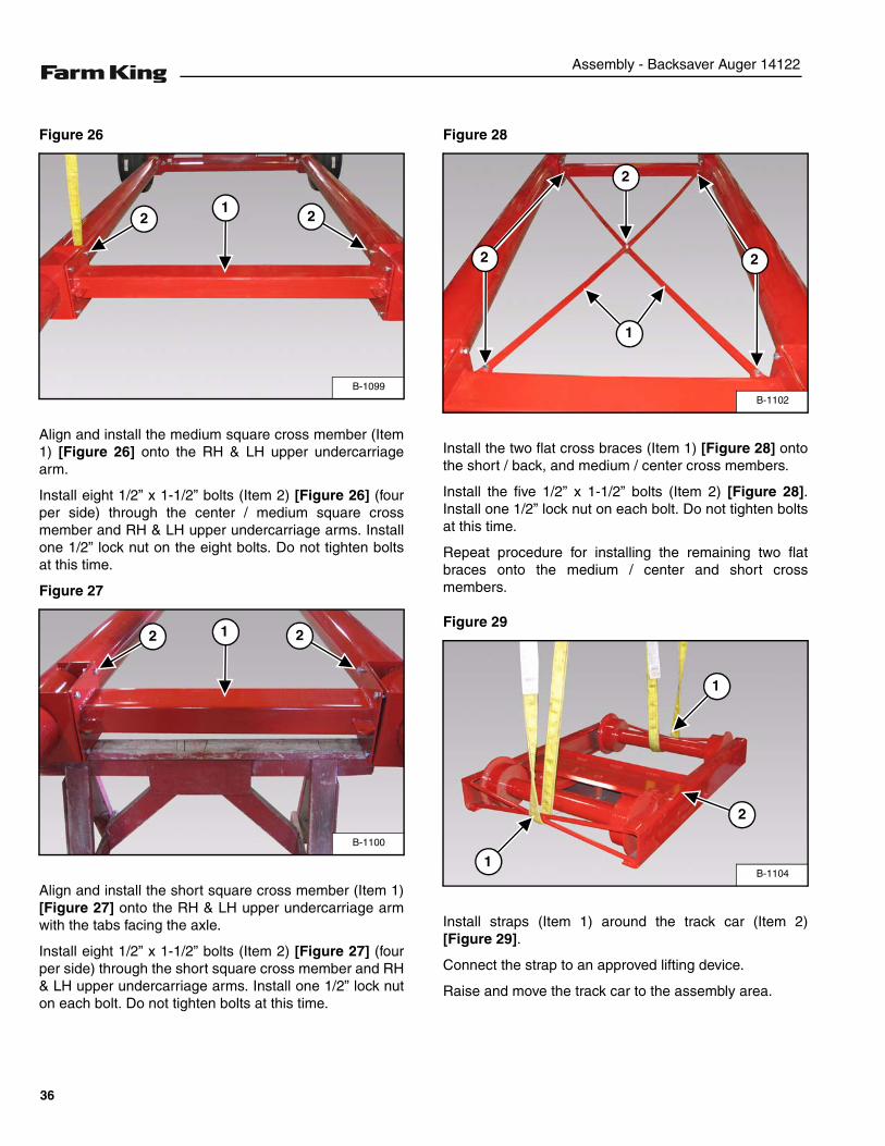
Figure 26
Align and install the medium square cross member (Item1) [Figure 26] onto the RH & LH upper undercarriagearm.
Install eight 1/2” x 1-1/2” bolts (Item 2) [Figure 26] (fourper side) through the center / medium square crossmember and RH & LH upper undercarriage arms. Installone 1/2” lock nut on the eight bolts. Do not tighten boltsat this time.
Figure 27
Align and install the short square cross member (Item 1)[Figure 27] onto the RH & LH upper undercarriage armwith the tabs facing the axle.
Install eight 1/2” x 1-1/2” bolts (Item 2) [Figure 27] (fourper side) through the short square cross member and RH& LH upper undercarriage arms. Install one 1/2” lock nuton each bolt. Do not tighten bolts at this time.
Figure 28
Install the two flat cross braces (Item 1) [Figure 28] ontothe short / back, and medium / center cross members.
Install the five 1/2” x 1-1/2” bolts (Item 2) [Figure 28].Install one 1/2” lock nut on each bolt. Do not tighten boltsat this time.
Repeat procedure for installing the remaining two flatbraces onto the medium / center and short crossmembers.
Figure 29
Install straps (Item 1) around the track car (Item 2)[Figure 29].
Connect the strap to an approved lifting device.
Raise and move the track car to the assembly area.
B-1099
122
B-1100
12 2
B-1102
2 2
1
2
B-11041
1
2
36

Assembly - Backsaver Auger 14122
Figure 30
Install one 1-1/4” - 10 ga. machine bushing (Item 1) andone 1/4” x 2” cotter pin (Item 2) onto the 1-1/4” x 40-1/4”pin (Item 3) [Figure 30].
Figure 31
Align the track car with the back end (away from the axle)of the RH & LH upper undercarriage arms as shown[Figure 31].
Install the 1-1/4” x 40-1/4” pin (Item 1) [Figure 31]through the LH upper undercarriage arm, track car andRH upper undercarriage arm.
Figure 32
Install one 1-1/4” - 10 ga. machine bushing (Item 1) andone 1/4” x 2” cotter pin (Item 2) [Figure 32] onto the 1-1/4” x 40-1/4” pin.
B-0264
3
1
2
B-1105
1
B-1106
1
2
37
Assembly - Backsaver Auger 14122
BASE GROUP (CONT’D)
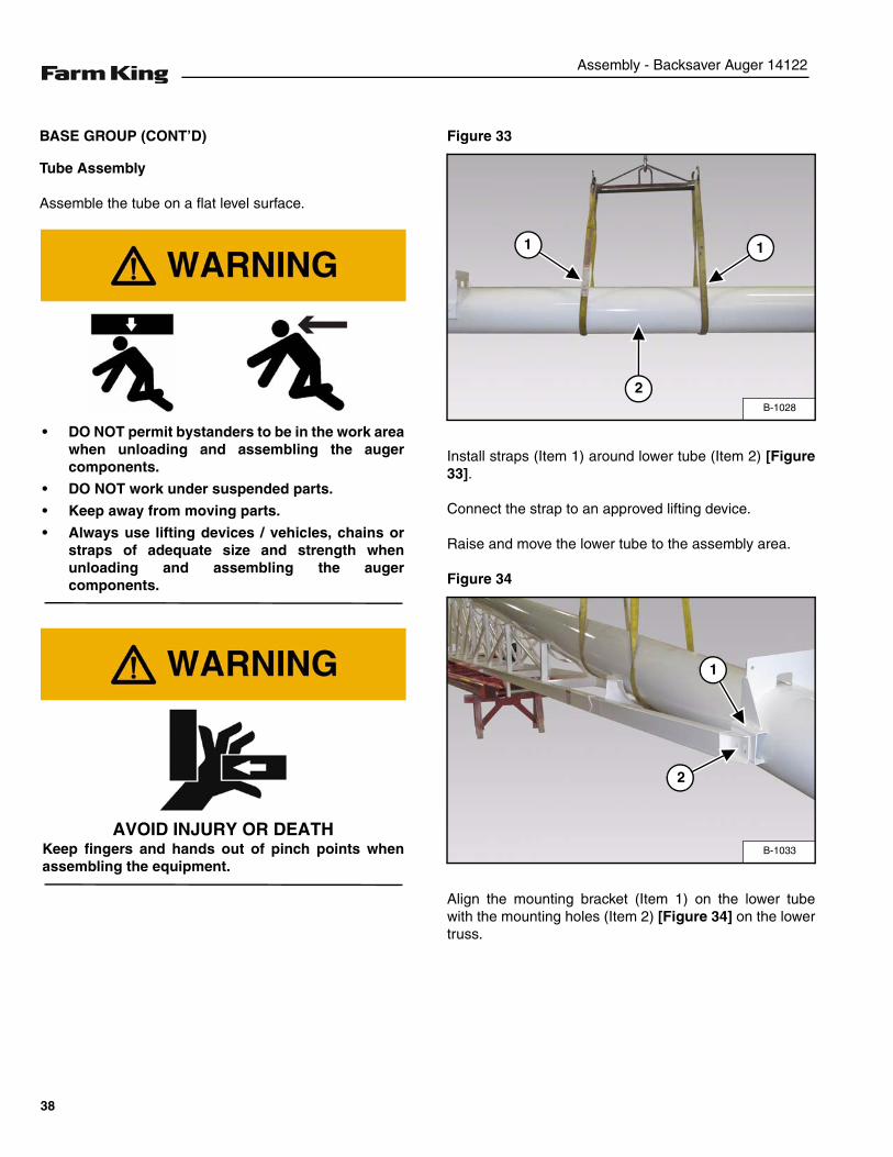
Tube Assembly
Assemble the tube on a flat level surface.
Figure 33
Install straps (Item 1) around lower tube (Item 2) [Figure33].
Connect the strap to an approved lifting device.
Raise and move the lower tube to the assembly area.
Figure 34
Align the mounting bracket (Item 1) on the lower tubewith the mounting holes (Item 2) [Figure 34] on the lowertruss.
• DO NOT permit bystanders to be in the work areawhen unloading and assembling the augercomponents.
• DO NOT work under suspended parts.
• Keep away from moving parts.
• Always use lifting devices / vehicles, chains orstraps of adequate size and strength whenunloading and assembling the augercomponents.
AVOID INJURY OR DEATHKeep fingers and hands out of pinch points whenassembling the equipment.
B-1028
1
2
1
B-1033
1
2
38
Assembly - Backsaver Auger 14122
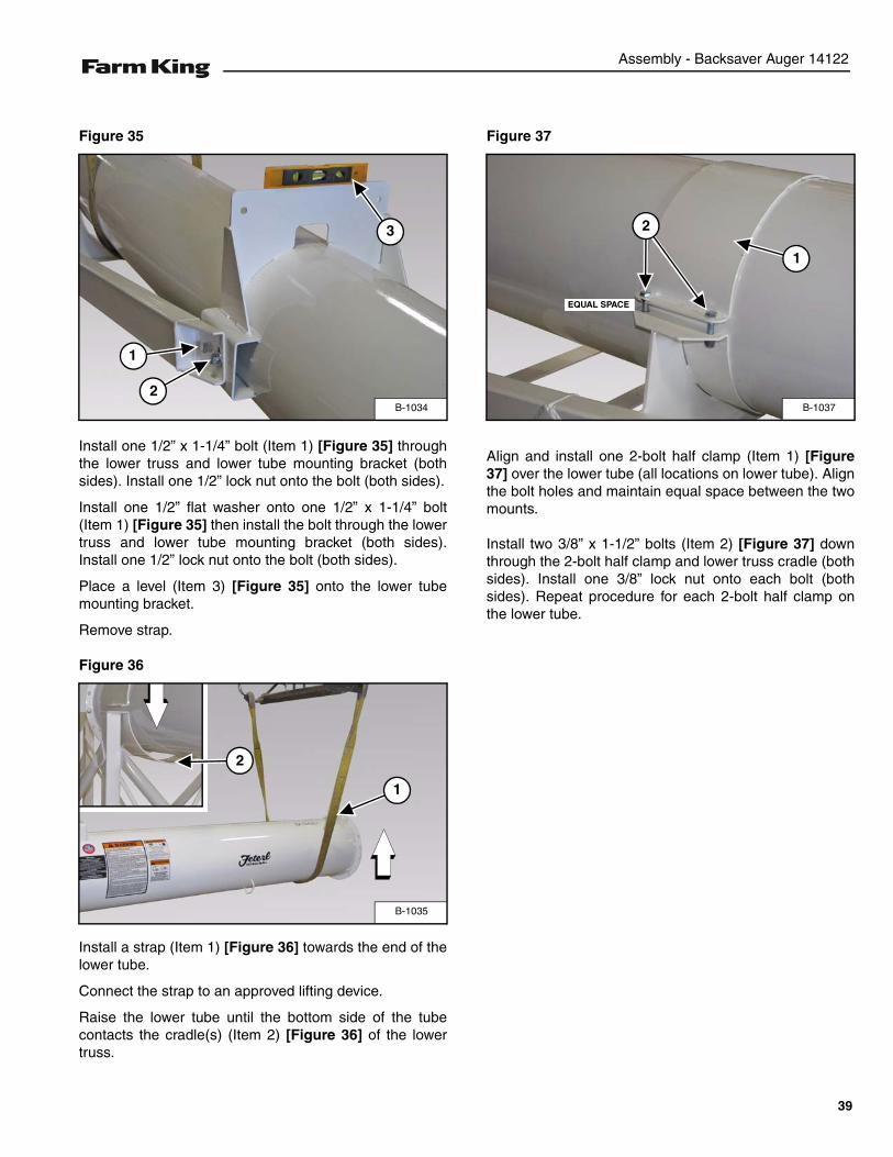
Figure 35
Install one 1/2” x 1-1/4” bolt (Item 1) [Figure 35] throughthe lower truss and lower tube mounting bracket (bothsides). Install one 1/2” lock nut onto the bolt (both sides).
Install one 1/2” flat washer onto one 1/2” x 1-1/4” bolt(Item 1) [Figure 35] then install the bolt through the lowertruss and lower tube mounting bracket (both sides).Install one 1/2” lock nut onto the bolt (both sides).
Place a level (Item 3) [Figure 35] onto the lower tubemounting bracket.
Remove strap.
Figure 36
Install a strap (Item 1) [Figure 36] towards the end of thelower tube.
Connect the strap to an approved lifting device.
Raise the lower tube until the bottom side of the tubecontacts the cradle(s) (Item 2) [Figure 36] of the lowertruss.
Figure 37
Align and install one 2-bolt half clamp (Item 1) [Figure37] over the lower tube (all locations on lower tube). Alignthe bolt holes and maintain equal space between the twomounts.
Install two 3/8” x 1-1/2” bolts (Item 2) [Figure 37] downthrough the 2-bolt half clamp and lower truss cradle (bothsides). Install one 3/8” lock nut onto each bolt (bothsides). Repeat procedure for each 2-bolt half clamp onthe lower tube.
B-1034
1
2
3
B-1035
1
2
B-1037
1
2
EQUAL SPACE
39
Assembly - Backsaver Auger 14122
Figure 38
Starting at the 2-bolt half clamp closest to the level, beginslowly tightening the 3/8” x 1-1/2” bolts (Item 1) [Figure38] and 3/8” lock nuts evenly on each side of the 2-bolthalf clamp. Visually inspect that the lower tube remainslevel as the bolts and nuts are being tightened. Tightenremaining 2-bolt half clamp bolts and nuts.
NOTE: Verify that the lower tube remains level as thebolts and nuts are being tightened.
Figure 39
Install a strap (Item 1) through the bracing of the uppertruss (Item 2) [Figure 39]. Connect the strap to anapproved lifting device.
Raise and move the upper truss to the assembly area.
Figure 40
Position the upper truss (Item 1) against the lower truss(Item 2) [Figure 40].
Using a punch (Item 3) [Figure 40], align the holes in thelower and upper trusses. Install 1/2” x 1-1/2” boltsthrough the two trusses. Install one 1/2” lock nut on eachbolt around the truss connecting plates.
Align the trusses and tighten the bolts and lock nuts.
When tightening the 2-bolt half clamp bolts andnuts, verify the lower tube remains level as each 2-bolt half clamp is tightened, and verify the lowertube remains level until the last 2-bolt half clamp onthe lower tube has been tightened.
B-1039
1
B-1108
1
1
2
B-1109
12
3
40
Assembly - Backsaver Auger 14122
Figure 41
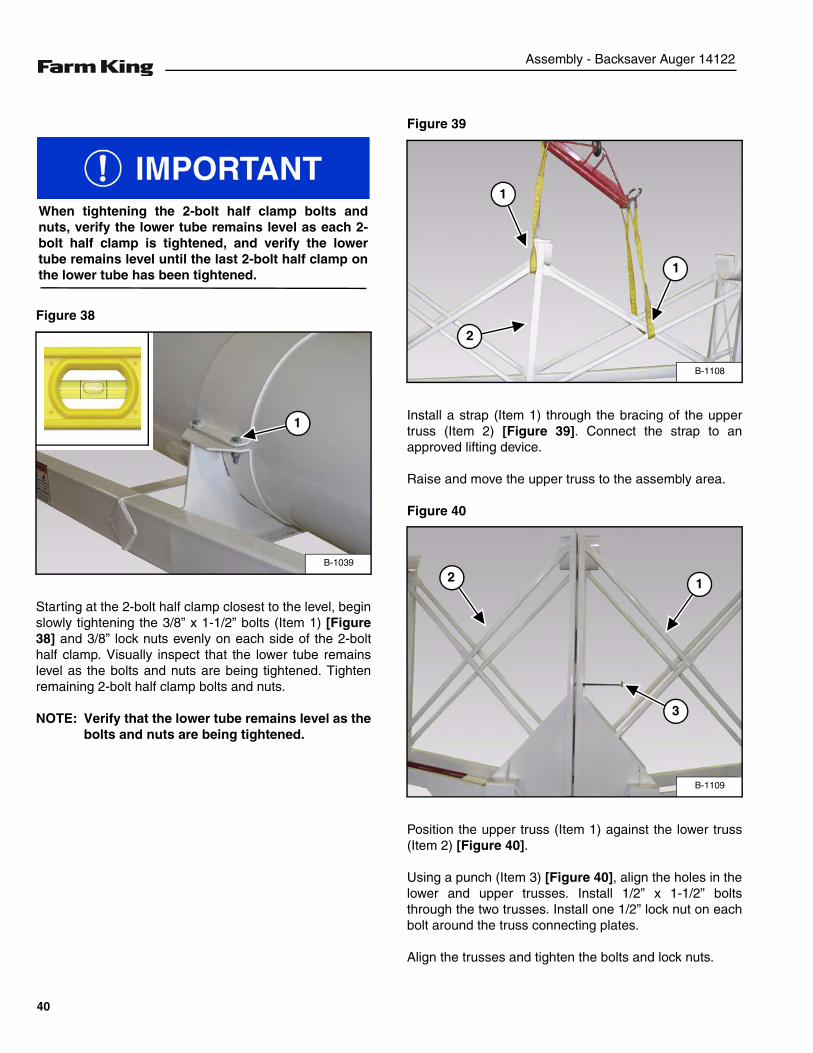
Install a strap around the center tube. Connect the strapto an approved lifting device.
Raise and move the lower truss to the assembly area.
Verify that the NOTICE decal (Item 1) end of the centertube is towards the intake end of the auger and the tubeseam (Item 2) [Figure 41] is facing up.
Figure 42
Place the center tube (Item 1) on the lower & uppertrusses towards the lower tube (Item 2) [Figure 42].
Slide flighting out of the lower & center tube sections toallow adequate space for connecting the two sections offlighting together [Figure 42].
Figure 43
Align the flighting shaft connecting holes (Item 1) [Figure43] and slide the flighting sections together.
Rotate the flighting sections to align the mounting holesin the flighting (Item 2) [Figure 43] is clear of themounting flange.
Install two 1/2”-20 UNF x 4-1/2” bolts through the flightingshaft connecting holes (Item 1) [Figure 43]. Install 1/2”lock nuts on the bolts and tighten.
Then install one 3/8” x 7/8” bolt through the flighting (Item2) [Figure 43]. Install a 3/8” lock nut on the bolt andtighten.
B-1112
1
2
B-1142
12
B-1143
1
2
41
Assembly - Backsaver Auger 14122
Figure 44
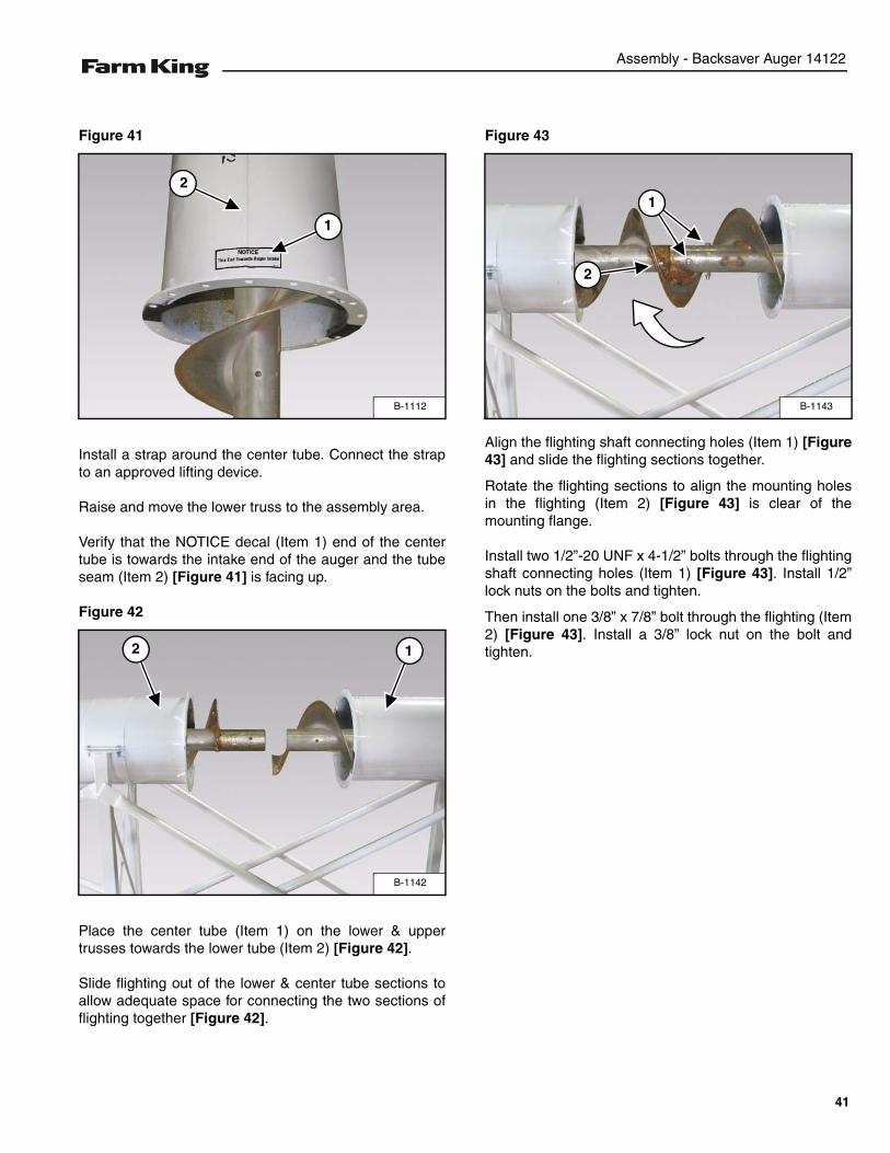
Slide the center tube (Item 1) against the lower tube(Item 2) [Figure 44]. Align the holes in the two flangesand install eighteen 1/2” x 1-1/2” bolts and lock nuts.
NOTE: Do not fully tighten bolts the first time. Fullytightening the bolts on one side will pull theauger tubes out of alignment.
Starting at the top, work around flange ring tighteningeach bolt a minimum of two times to gradually pull thetwo tube flanges together. Tighten the bolts until the twoflanges have made full contact.
Figure 45
Install straps (Item 1) around the upper truss (Item 2)[Figure 45].
Connect the strap to an approved lifting device.
Raise the upper truss until the bottom of the center tubemakes contact with the upper truss tube cradles.
NOTE: Do not attempt to pull the center tube downinto the upper truss tube cradles.
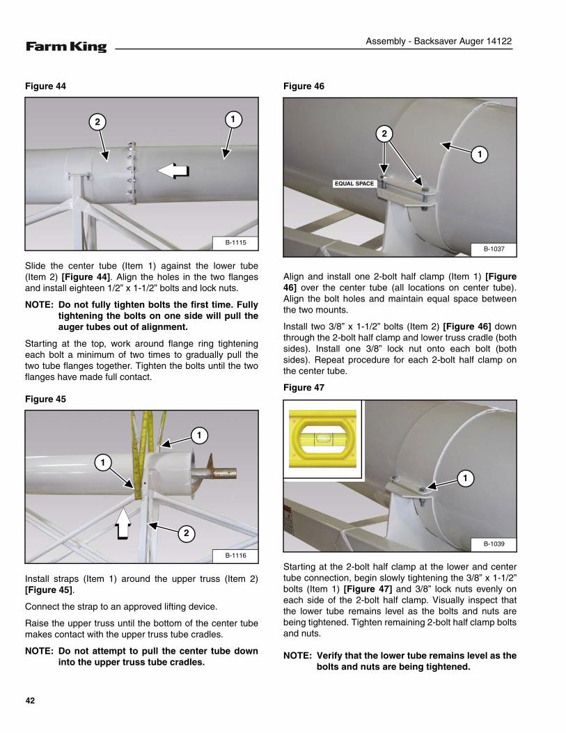
Figure 46
Align and install one 2-bolt half clamp (Item 1) [Figure46] over the center tube (all locations on center tube).Align the bolt holes and maintain equal space betweenthe two mounts.
Install two 3/8” x 1-1/2” bolts (Item 2) [Figure 46] downthrough the 2-bolt half clamp and lower truss cradle (bothsides). Install one 3/8” lock nut onto each bolt (bothsides). Repeat procedure for each 2-bolt half clamp onthe center tube.
Figure 47
Starting at the 2-bolt half clamp at the lower and centertube connection, begin slowly tightening the 3/8” x 1-1/2”bolts (Item 1) [Figure 47] and 3/8” lock nuts evenly oneach side of the 2-bolt half clamp. Visually inspect thatthe lower tube remains level as the bolts and nuts arebeing tightened. Tighten remaining 2-bolt half clamp boltsand nuts.
NOTE: Verify that the lower tube remains level as thebolts and nuts are being tightened.
B-1115
12
B-1116
1
2
1
B-1037
1
2
EQUAL SPACE
B-1039
1
42
Assembly - Backsaver Auger 14122
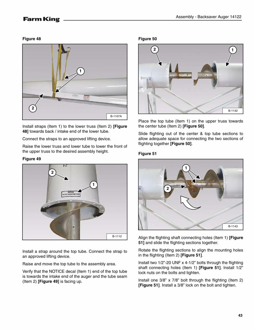
Figure 48
Install straps (Item 1) to the lower truss (Item 2) [Figure48] towards back / intake end of the lower tube.
Connect the straps to an approved lifting device.
Raise the lower truss and lower tube to lower the front ofthe upper truss to the desired assembly height.
Figure 49
Install a strap around the top tube. Connect the strap toan approved lifting device.
Raise and move the top tube to the assembly area.
Verify that the NOTICE decal (Item 1) end of the top tubeis towards the intake end of the auger and the tube seam(Item 2) [Figure 49] is facing up.
Figure 50
Place the top tube (Item 1) on the upper truss towardsthe center tube (Item 2) [Figure 50].
Slide flighting out of the center & top tube sections toallow adequate space for connecting the two sections offlighting together [Figure 50].
Figure 51
Align the flighting shaft connecting holes (Item 1) [Figure51] and slide the flighting sections together.
Rotate the flighting sections to align the mounting holesin the flighting (Item 2) [Figure 51].
Install two 1/2”-20 UNF x 4-1/2” bolts through the flightingshaft connecting holes (Item 1) [Figure 51]. Install 1/2”lock nuts on the bolts and tighten.
Install one 3/8” x 7/8” bolt through the flighting (Item 2)[Figure 51]. Install a 3/8” lock on the bolt and tighten.
B-1107A
2
1
B-1112
1
2
B-1142
12
B-1143
1
2
43
Assembly - Backsaver Auger 14122
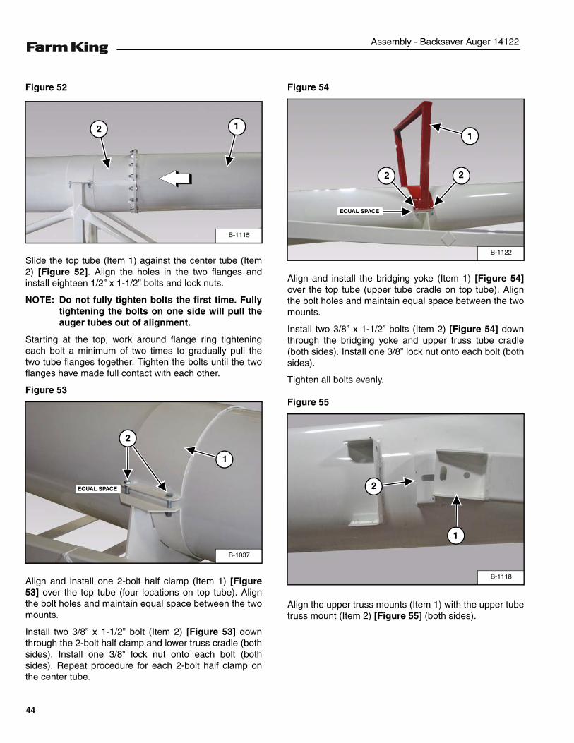
Figure 52
Slide the top tube (Item 1) against the center tube (Item2) [Figure 52]. Align the holes in the two flanges andinstall eighteen 1/2” x 1-1/2” bolts and lock nuts.
NOTE: Do not fully tighten bolts the first time. Fullytightening the bolts on one side will pull theauger tubes out of alignment.
Starting at the top, work around flange ring tighteningeach bolt a minimum of two times to gradually pull thetwo tube flanges together. Tighten the bolts until the twoflanges have made full contact with each other.
Figure 53
Align and install one 2-bolt half clamp (Item 1) [Figure53] over the top tube (four locations on top tube). Alignthe bolt holes and maintain equal space between the twomounts.
Install two 3/8” x 1-1/2” bolt (Item 2) [Figure 53] downthrough the 2-bolt half clamp and lower truss cradle (bothsides). Install one 3/8” lock nut onto each bolt (bothsides). Repeat procedure for each 2-bolt half clamp onthe center tube.
Figure 54
Align and install the bridging yoke (Item 1) [Figure 54]over the top tube (upper tube cradle on top tube). Alignthe bolt holes and maintain equal space between the twomounts.
Install two 3/8” x 1-1/2” bolts (Item 2) [Figure 54] downthrough the bridging yoke and upper truss tube cradle(both sides). Install one 3/8” lock nut onto each bolt (bothsides).
Tighten all bolts evenly.
Figure 55
Align the upper truss mounts (Item 1) with the upper tubetruss mount (Item 2) [Figure 55] (both sides).
B-1115
12
B-1037
1
2
EQUAL SPACE
B-1122
1
EQUAL SPACE
2 2
B-1118
2
1
44
Assembly - Backsaver Auger 14122
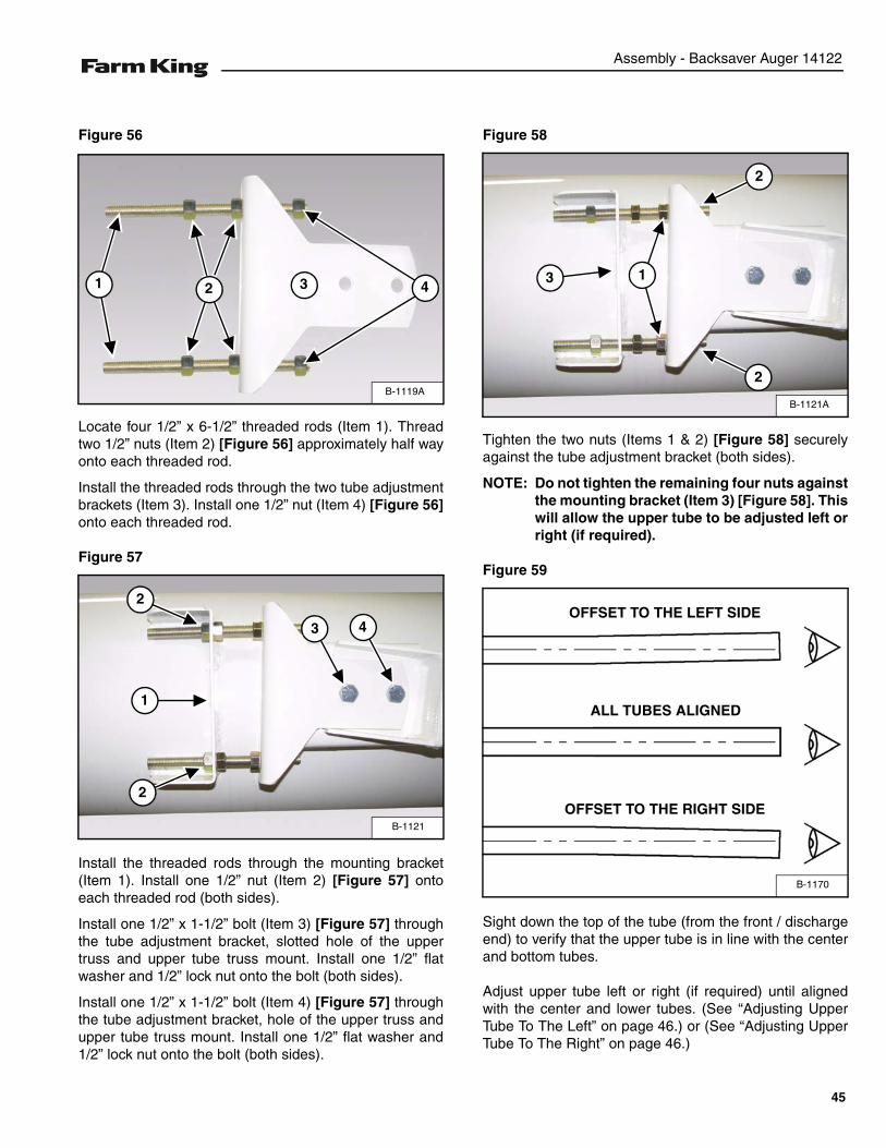
Figure 56
Locate four 1/2” x 6-1/2” threaded rods (Item 1). Threadtwo 1/2” nuts (Item 2) [Figure 56] approximately half wayonto each threaded rod.
Install the threaded rods through the two tube adjustmentbrackets (Item 3). Install one 1/2” nut (Item 4) [Figure 56]onto each threaded rod.
Figure 57
Install the threaded rods through the mounting bracket(Item 1). Install one 1/2” nut (Item 2) [Figure 57] ontoeach threaded rod (both sides).
Install one 1/2” x 1-1/2” bolt (Item 3) [Figure 57] throughthe tube adjustment bracket, slotted hole of the uppertruss and upper tube truss mount. Install one 1/2” flatwasher and 1/2” lock nut onto the bolt (both sides).
Install one 1/2” x 1-1/2” bolt (Item 4) [Figure 57] throughthe tube adjustment bracket, hole of the upper truss andupper tube truss mount. Install one 1/2” flat washer and1/2” lock nut onto the bolt (both sides).
Figure 58
Tighten the two nuts (Items 1 & 2) [Figure 58] securelyagainst the tube adjustment bracket (both sides).
NOTE: Do not tighten the remaining four nuts againstthe mounting bracket (Item 3) [Figure 58]. Thiswill allow the upper tube to be adjusted left orright (if required).
Figure 59
Sight down the top of the tube (from the front / dischargeend) to verify that the upper tube is in line with the centerand bottom tubes.
Adjust upper tube left or right (if required) until alignedwith the center and lower tubes. (See “Adjusting UpperTube To The Left” on page 46.) or (See “Adjusting UpperTube To The Right” on page 46.)
B-1119A
1 2 3 4
B-1121
1
2
2
3 4
B-1121A
1
2
2
3
B-1170
OFFSET TO THE LEFT SIDE
OFFSET TO THE RIGHT SIDE
ALL TUBES ALIGNED
45
Assembly - Backsaver Auger 14122
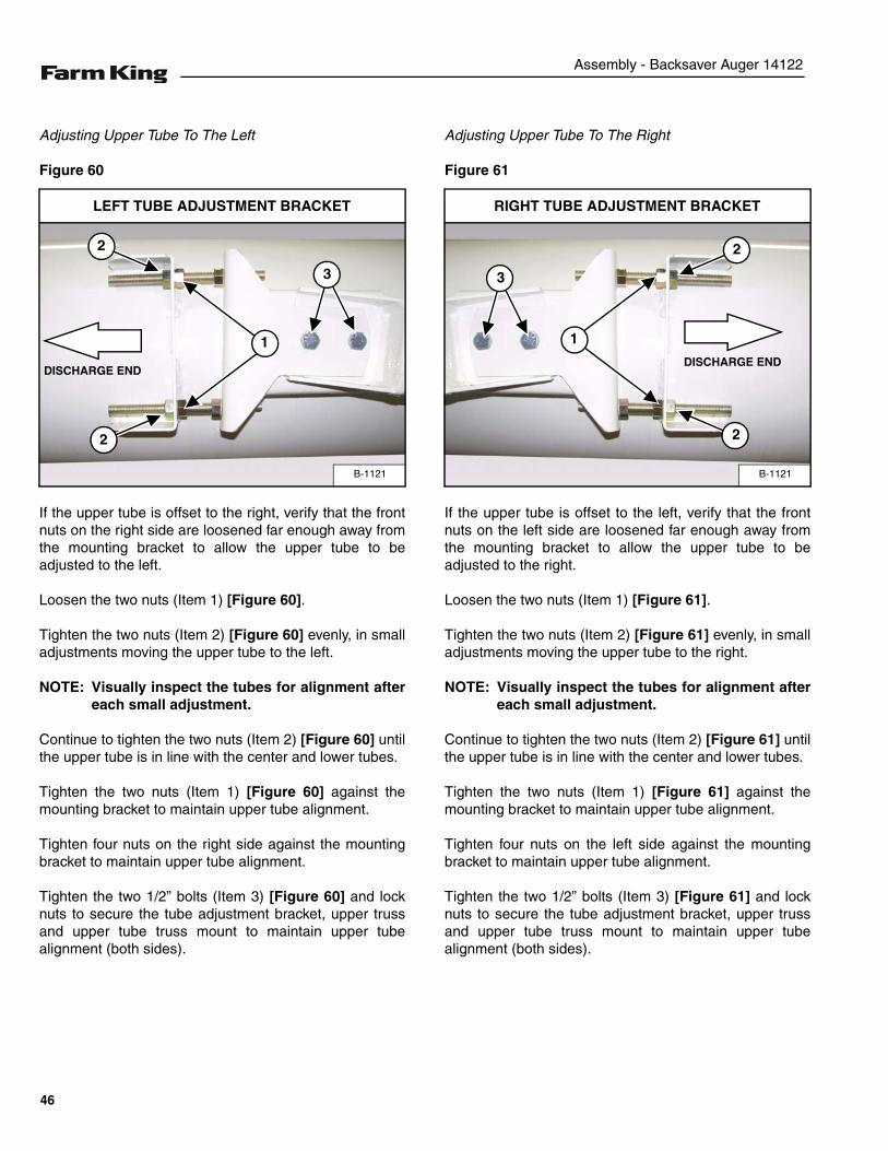
Adjusting Upper Tube To The Left
Figure 60
If the upper tube is offset to the right, verify that the frontnuts on the right side are loosened far enough away fromthe mounting bracket to allow the upper tube to beadjusted to the left.
Loosen the two nuts (Item 1) [Figure 60].
Tighten the two nuts (Item 2) [Figure 60] evenly, in smalladjustments moving the upper tube to the left.
NOTE: Visually inspect the tubes for alignment aftereach small adjustment.
Continue to tighten the two nuts (Item 2) [Figure 60] untilthe upper tube is in line with the center and lower tubes.
Tighten the two nuts (Item 1) [Figure 60] against themounting bracket to maintain upper tube alignment.
Tighten four nuts on the right side against the mountingbracket to maintain upper tube alignment.
Tighten the two 1/2” bolts (Item 3) [Figure 60] and locknuts to secure the tube adjustment bracket, upper trussand upper tube truss mount to maintain upper tubealignment (both sides).
Adjusting Upper Tube To The Right
Figure 61
If the upper tube is offset to the left, verify that the frontnuts on the left side are loosened far enough away fromthe mounting bracket to allow the upper tube to beadjusted to the right.
Loosen the two nuts (Item 1) [Figure 61].
Tighten the two nuts (Item 2) [Figure 61] evenly, in smalladjustments moving the upper tube to the right.
NOTE: Visually inspect the tubes for alignment aftereach small adjustment.
Continue to tighten the two nuts (Item 2) [Figure 61] untilthe upper tube is in line with the center and lower tubes.
Tighten the two nuts (Item 1) [Figure 61] against themounting bracket to maintain upper tube alignment.
Tighten four nuts on the left side against the mountingbracket to maintain upper tube alignment.
Tighten the two 1/2” bolts (Item 3) [Figure 61] and locknuts to secure the tube adjustment bracket, upper trussand upper tube truss mount to maintain upper tubealignment (both sides).
B-1121
2
2
LEFT TUBE ADJUSTMENT BRACKET
1
3
DISCHARGE END
B-1121
2
2
RIGHT TUBE ADJUSTMENT BRACKET
1
3
DISCHARGE END
46
Assembly - Backsaver Auger 14122
Figure 62
Install straps (Item 1) through the drive section (Item 2)[Figure 62] as shown.
Connect the straps to an approved lifting device.
Raise and move the drive section to the assembly area.
Figure 63
Align the drive section (Item 1) with the lower tube (Item2) [Figure 63].
Slide flighting out of the drive section & tube sections toallow adequate space for connecting the drive section &tube sections of flighting together [Figure 63].
Figure 64
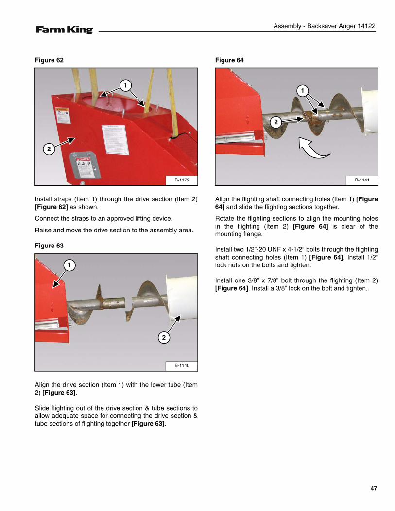
Align the flighting shaft connecting holes (Item 1) [Figure64] and slide the flighting sections together.
Rotate the flighting sections to align the mounting holesin the flighting (Item 2) [Figure 64] is clear of themounting flange.
Install two 1/2”-20 UNF x 4-1/2” bolts through the flightingshaft connecting holes (Item 1) [Figure 64]. Install 1/2”lock nuts on the bolts and tighten.
Install one 3/8” x 7/8” bolt through the flighting (Item 2)[Figure 64]. Install a 3/8” lock on the bolt and tighten.
B-1172
1
2
B-1140
2
1
B-1141
1
2
47
Assembly - Backsaver Auger 14122
Figure 65
Move the drive section (Item 1) towards the lower tube(Item 2) [Figure 65].
Align the 1/2” studs with the lower tube flange mountingholes.
Align and install 1/2” - 1-1/2” bolts through the drivesection and lower tube flange (from the inside of the drivesection) open holes.
Install 1/2” lock nuts onto the 1/2” studs and 1/2” x 1-1/2”bolts.
Starting at the top, work around flange ring tighteningeach bolt a minimum of two times to gradually pull thedrive section and lower tube flanges together. Tightenthe bolts until the two flanges have made full contact witheach other.
Figure 66
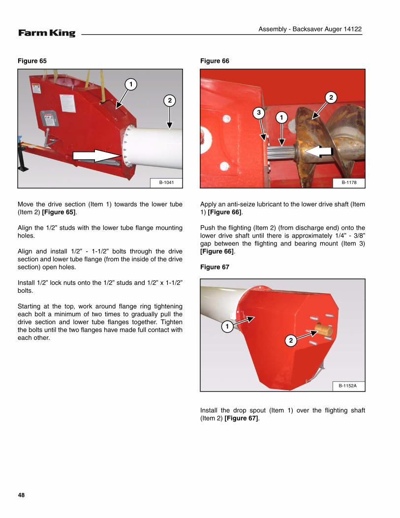
Apply an anti-seize lubricant to the lower drive shaft (Item1) [Figure 66].
Push the flighting (Item 2) (from discharge end) onto thelower drive shaft until there is approximately 1/4” - 3/8”gap between the flighting and bearing mount (Item 3)[Figure 66].
Figure 67
Install the drop spout (Item 1) over the flighting shaft(Item 2) [Figure 67].
B-1041
2
1
B-1178
2
31
B-1152A
1
2
48
Assembly - Backsaver Auger 14122
Figure 68
Install nine eight 1/2” x 1-1/2” bolts (Item 1) [Figure 68]through the drop spout and upper tube flange. Install 1/2”lock nuts on the bolts and tighten.
Figure 69
Install the bearing / bearing flange (Item 1) onto the four5/8” studs. Install four 5/8” lock nuts (Item 2) [Figure 69]on the studs and tighten.
Figure 70
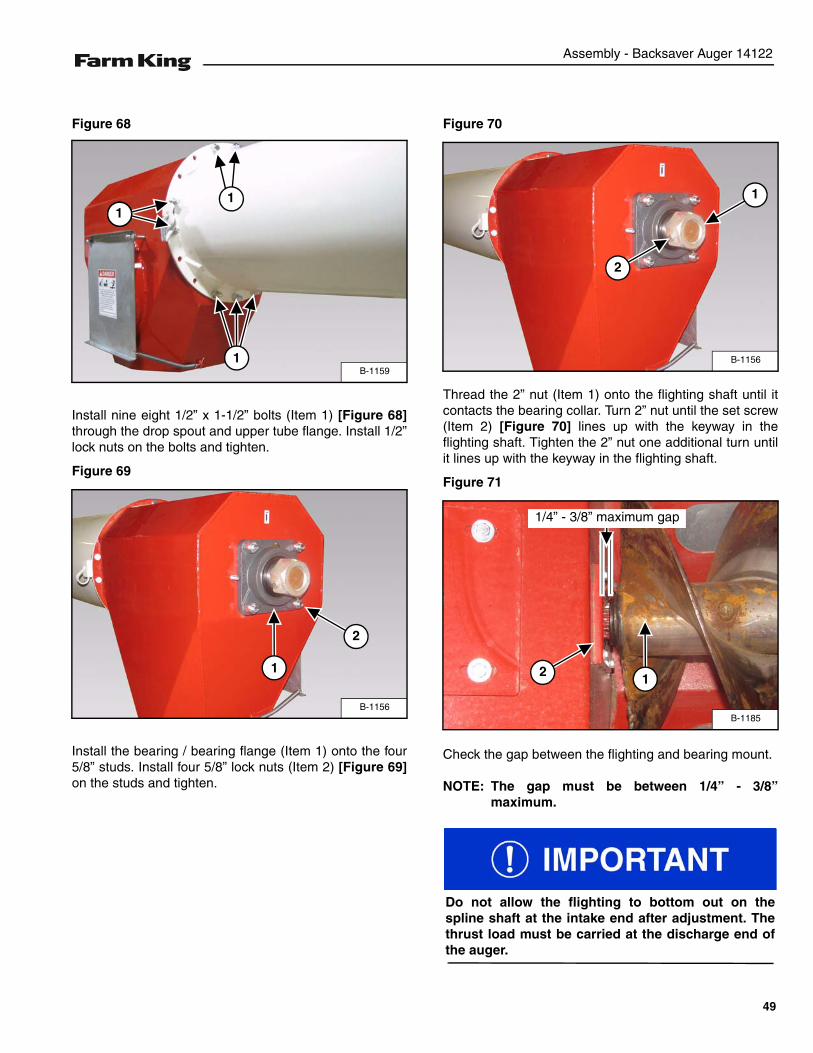
Thread the 2” nut (Item 1) onto the flighting shaft until itcontacts the bearing collar. Turn 2” nut until the set screw(Item 2) [Figure 70] lines up with the keyway in theflighting shaft. Tighten the 2” nut one additional turn untilit lines up with the keyway in the flighting shaft.
Figure 71
Check the gap between the flighting and bearing mount.
NOTE: The gap must be between 1/4” - 3/8”maximum.
B-1159
111
1
B-1156
1
2
B-1156
1
2
B-1185
12
1/4” - 3/8” maximum gap
Do not allow the flighting to bottom out on thespline shaft at the intake end after adjustment. Thethrust load must be carried at the discharge end ofthe auger.
49
Assembly - Backsaver Auger 14122
Figure 72
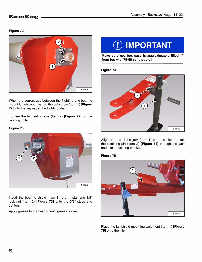
When the correct gap between the flighting and bearingmount is achieved, tighten the set screw (Item 1) [Figure72] into the keyway in the flighting shaft.
Tighten the two set screws (Item 2) [Figure 72] on thebearing collar.
Figure 73
Install the bearing shield (Item 1), then install one 3/8”lock nut (Item 2) [Figure 73] onto the 3/8” studs andtighten.
Apply grease to the bearing until grease shows.
Figure 74
Align and install the jack (Item 1) onto the hitch. Installthe retaining pin (Item 2) [Figure 74] through the jackand hitch mounting bracket.
Figure 75
Place the fan shield mounting weldment (Item 1) [Figure75] onto the hitch.
B-1156
1
2
B-1164
1 2
Make sure gearbox case is approximately filled 1”from top with 75-90 synthetic oil
B-1042
1
2
B-1044
1
50
Assembly - Backsaver Auger 14122
Figure 76
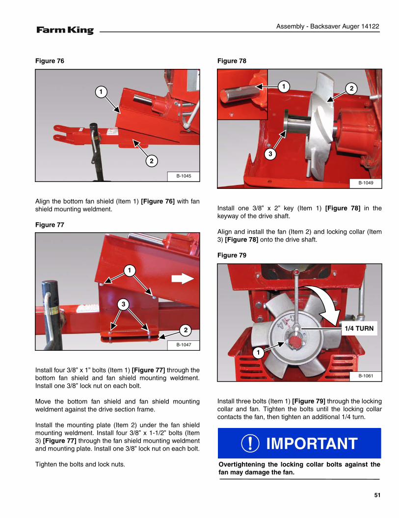
Align the bottom fan shield (Item 1) [Figure 76] with fanshield mounting weldment.
Figure 77
Install four 3/8” x 1” bolts (Item 1) [Figure 77] through thebottom fan shield and fan shield mounting weldment.Install one 3/8” lock nut on each bolt.
Move the bottom fan shield and fan shield mountingweldment against the drive section frame.
Install the mounting plate (Item 2) under the fan shieldmounting weldment. Install four 3/8” x 1-1/2” bolts (Item3) [Figure 77] through the fan shield mounting weldmentand mounting plate. Install one 3/8” lock nut on each bolt.
Tighten the bolts and lock nuts.
Figure 78
Install one 3/8” x 2” key (Item 1) [Figure 78] in thekeyway of the drive shaft.
Align and install the fan (Item 2) and locking collar (Item3) [Figure 78] onto the drive shaft.
Figure 79
Install three bolts (Item 1) [Figure 79] through the lockingcollar and fan. Tighten the bolts until the locking collarcontacts the fan, then tighten an additional 1/4 turn.
B-1045
1
2
B-1047
1
2
3
B-1049
1 2
3
B-1061
1
1/4 TURN
Overtightening the locking collar bolts against thefan may damage the fan.
51
Assembly - Backsaver Auger 14122
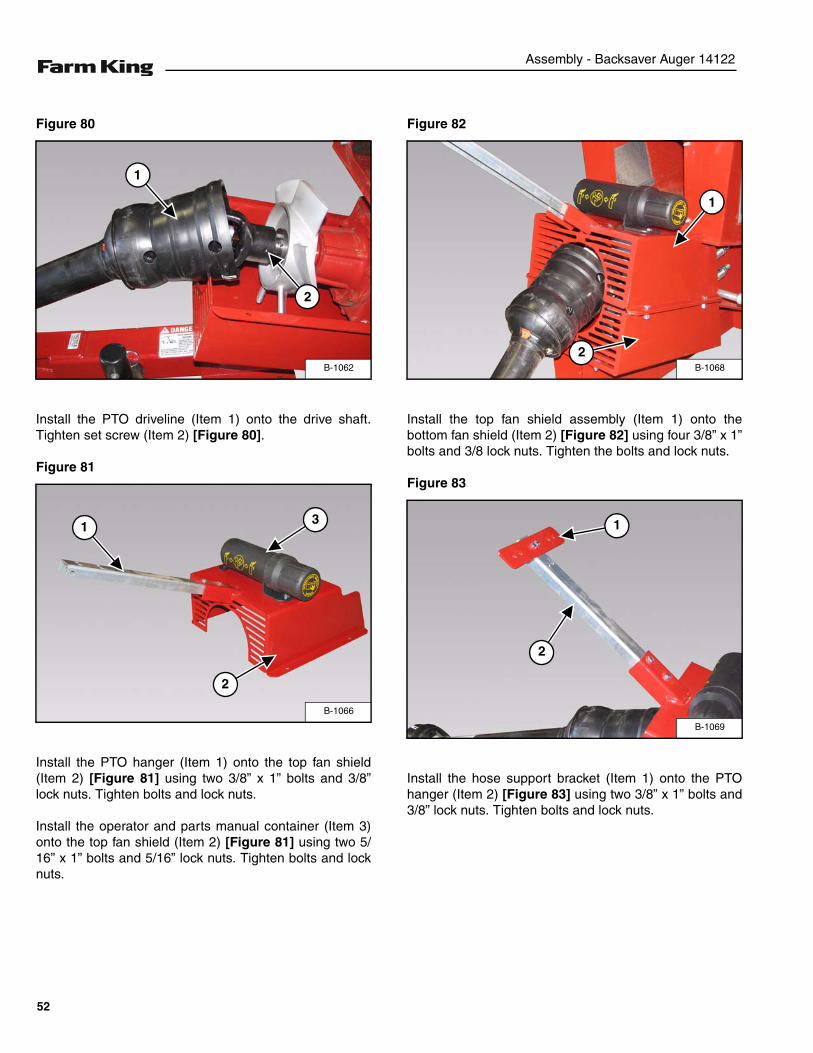
Figure 80
Install the PTO driveline (Item 1) onto the drive shaft.Tighten set screw (Item 2) [Figure 80].
Figure 81
Install the PTO hanger (Item 1) onto the top fan shield(Item 2) [Figure 81] using two 3/8” x 1” bolts and 3/8”lock nuts. Tighten bolts and lock nuts.
Install the operator and parts manual container (Item 3)onto the top fan shield (Item 2) [Figure 81] using two 5/16” x 1” bolts and 5/16” lock nuts. Tighten bolts and locknuts.
Figure 82
Install the top fan shield assembly (Item 1) onto thebottom fan shield (Item 2) [Figure 82] using four 3/8” x 1”bolts and 3/8 lock nuts. Tighten the bolts and lock nuts.
Figure 83
Install the hose support bracket (Item 1) onto the PTOhanger (Item 2) [Figure 83] using two 3/8” x 1” bolts and3/8” lock nuts. Tighten bolts and lock nuts.
B-1062
1
2
B-1066
1
2
3
B-1068
1
2
B-1069
1
2
52
Assembly - Backsaver Auger 14122
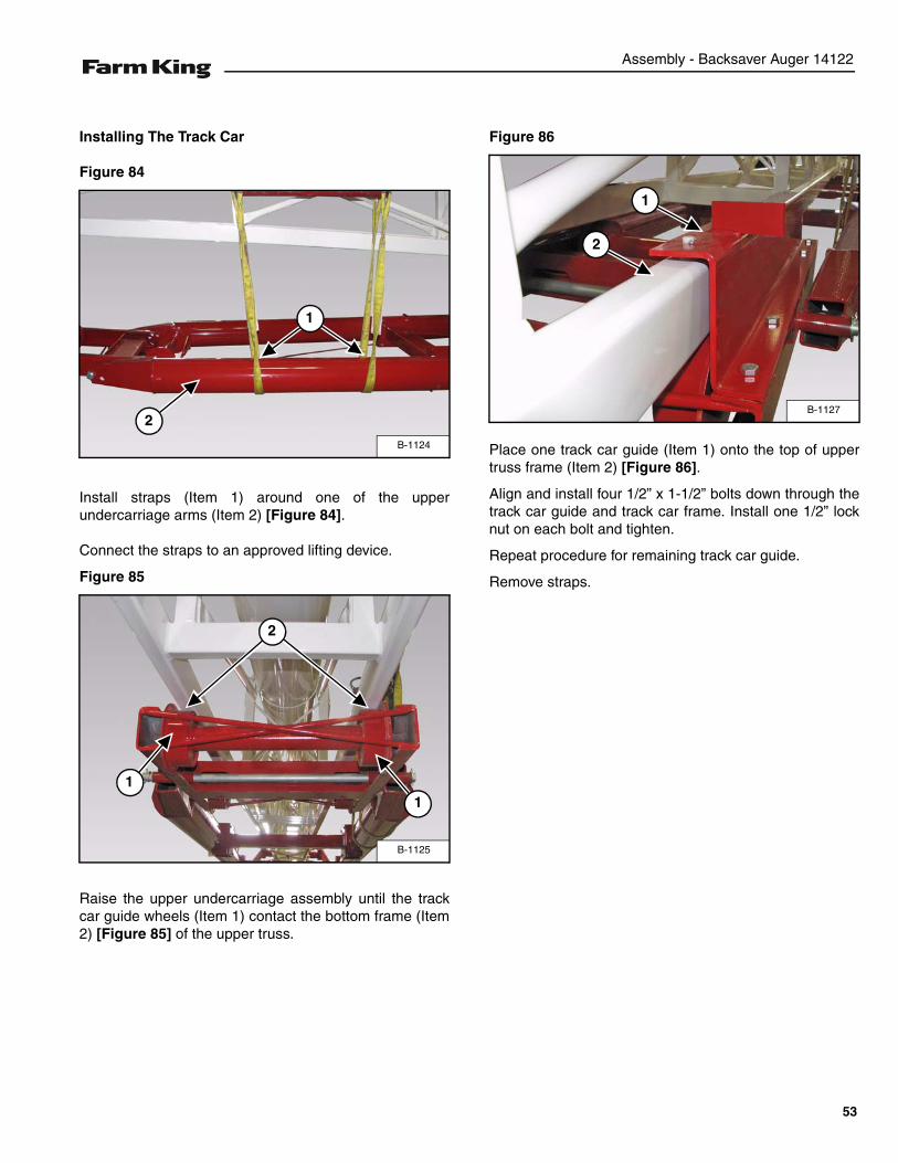
Installing The Track Car
Figure 84
Install straps (Item 1) around one of the upperundercarriage arms (Item 2) [Figure 84].
Connect the straps to an approved lifting device.
Figure 85
Raise the upper undercarriage assembly until the trackcar guide wheels (Item 1) contact the bottom frame (Item2) [Figure 85] of the upper truss.
Figure 86
Place one track car guide (Item 1) onto the top of uppertruss frame (Item 2) [Figure 86].
Align and install four 1/2” x 1-1/2” bolts down through thetrack car guide and track car frame. Install one 1/2” locknut on each bolt and tighten.
Repeat procedure for remaining track car guide.
Remove straps.
B-1124
2
1
B-1125
2
11
B-1127
1
2
53
Assembly - Backsaver Auger 14122
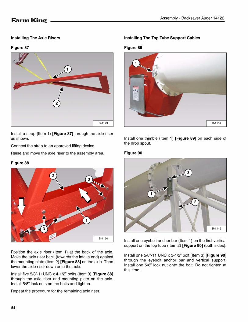
Installing The Axle Risers
Figure 87
Install a strap (Item 1) [Figure 87] through the axle riseras shown.
Connect the strap to an approved lifting device.
Raise and move the axle riser to the assembly area.
Figure 88
Position the axle riser (Item 1) at the back of the axle.Move the axle riser back (towards the intake end) againstthe mounting plate (Item 2) [Figure 88] on the axle. Thenlower the axle riser down onto the axle.
Install five 5/8”-11UNC x 4-1/2” bolts (Item 3) [Figure 88]through the axle riser and mounting plate on the axle.Install 5/8” lock nuts on the bolts and tighten.
Repeat the procedure for the remaining axle riser.
Installing The Top Tube Support Cables
Figure 89
Install one thimble (Item 1) [Figure 89] on each side ofthe drop spout.
Figure 90
Install one eyebolt anchor bar (Item 1) on the first verticalsupport on the top tube (Item 2) [Figure 90] (both sides).
Install one 5/8”-11 UNC x 3-1/2” bolt (Item 3) [Figure 90]through the eyebolt anchor bar and vertical support.Install one 5/8” lock nut onto the bolt. Do not tighten atthis time.
B-1129
1
2
B-1130
1
3
23
B-1159
1
B-1146
1
2
3
54
Assembly - Backsaver Auger 14122
Figure 91
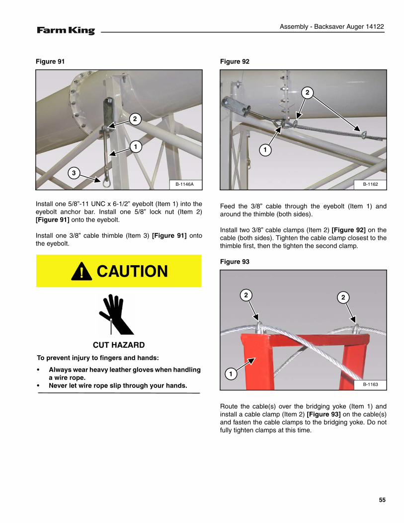
Install one 5/8”-11 UNC x 6-1/2” eyebolt (Item 1) into theeyebolt anchor bar. Install one 5/8” lock nut (Item 2)[Figure 91] onto the eyebolt.
Install one 3/8” cable thimble (Item 3) [Figure 91] ontothe eyebolt.
Figure 92
Feed the 3/8” cable through the eyebolt (Item 1) andaround the thimble (both sides).
Install two 3/8” cable clamps (Item 2) [Figure 92] on thecable (both sides). Tighten the cable clamp closest to thethimble first, then the tighten the second clamp.
Figure 93
Route the cable(s) over the bridging yoke (Item 1) andinstall a cable clamp (Item 2) [Figure 93] on the cable(s)and fasten the cable clamps to the bridging yoke. Do notfully tighten clamps at this time.
B-1146A
2
3
1
CUT HAZARD
To prevent injury to fingers and hands:
• Always wear heavy leather gloves when handlinga wire rope.
• Never let wire rope slip through your hands.
B-1162
2
1
B-1163
2 2
1
55
Assembly - Backsaver Auger 14122
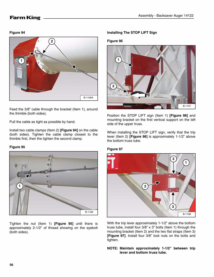
Figure 94
Feed the 3/8” cable through the bracket (Item 1), aroundthe thimble (both sides).
Pull the cable as tight as possible by hand.
Install two cable clamps (Item 2) [Figure 94] on the cable(both sides). Tighten the cable clamp closest to thethimble first, then the tighten the second clamp.
Figure 95
Tighten the nut (Item 1) [Figure 95] until there isapproximately 2-1/2” of thread showing on the eyebolt(both sides).
Installing The STOP LIFT Sign
Figure 96
Position the STOP LIFT sign (Item 1) [Figure 96] andmounting bracket on the first vertical support on the leftside of the upper truss.
When installing the STOP LIFT sign, verify that the triplever (Item 2) [Figure 96] is approximately 1-1/2” abovethe bottom truss tube.
Figure 97
With the trip lever approximately 1-1/2” above the bottomtruss tube, install four 3/8” x 3” bolts (Item 1) through themounting bracket (Item 2) and the two flat straps (Item 3)[Figure 97]. Install four 3/8” lock nuts on the bolts andtighten.
NOTE: Maintain approximately 1-1/2” between triplever and bottom truss tube.
B-1159A
1
2
B-1165
1
B-1137
1
2
B-1138
3
3
2
1
56
Assembly - Backsaver Auger 14122
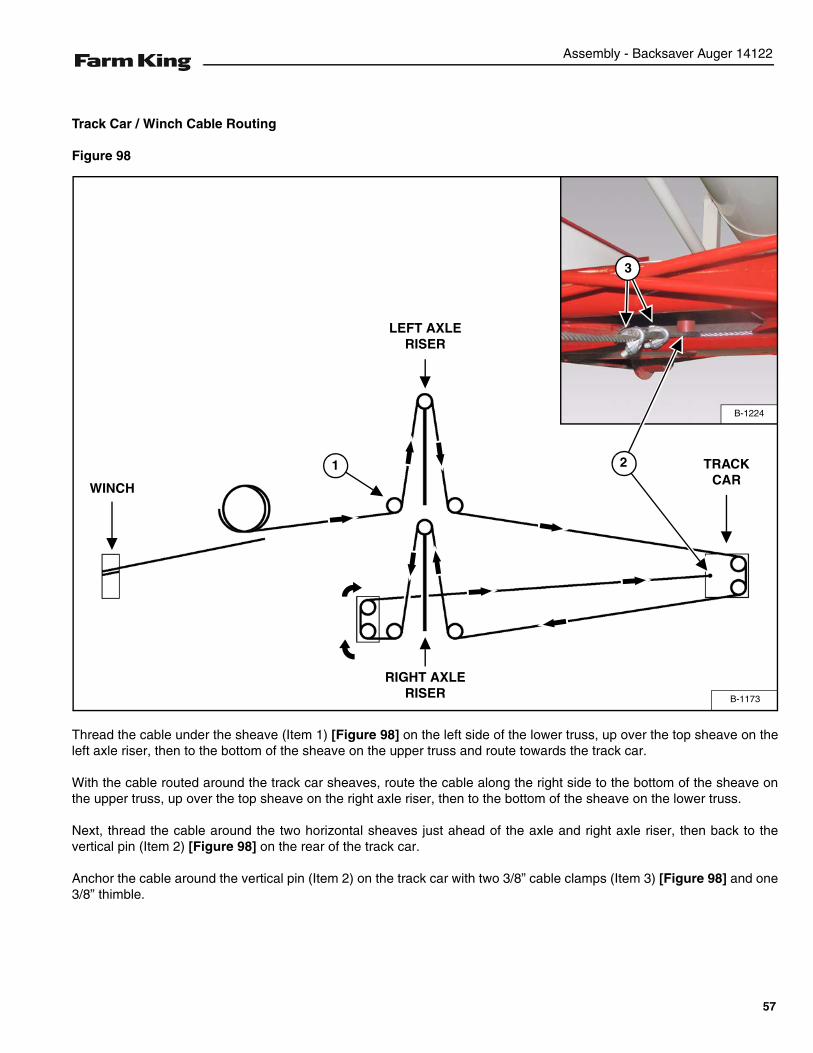
Track Car / Winch Cable Routing
Figure 98
Thread the cable under the sheave (Item 1) [Figure 98] on the left side of the lower truss, up over the top sheave on theleft axle riser, then to the bottom of the sheave on the upper truss and route towards the track car.
With the cable routed around the track car sheaves, route the cable along the right side to the bottom of the sheave onthe upper truss, up over the top sheave on the right axle riser, then to the bottom of the sheave on the lower truss.
Next, thread the cable around the two horizontal sheaves just ahead of the axle and right axle riser, then back to thevertical pin (Item 2) [Figure 98] on the rear of the track car.
Anchor the cable around the vertical pin (Item 2) on the track car with two 3/8” cable clamps (Item 3) [Figure 98] and one3/8” thimble.
B-1173
1
LEFT AXLE RISER
RIGHT AXLE RISER
TRACK CAR
WINCH
B-1224
3
2
57
Assembly - Backsaver Auger 14122
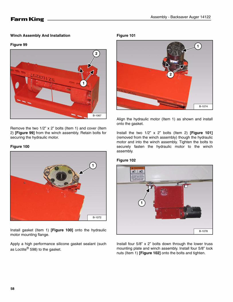
Winch Assembly And Installation
Figure 99
Remove the two 1/2” x 2” bolts (Item 1) and cover (Item2) [Figure 99] from the winch assembly. Retain bolts forsecuring the hydraulic motor.
Figure 100
Install gasket (Item 1) [Figure 100] onto the hydraulicmotor mounting flange.
Apply a high performance silicone gasket sealant (such
as Loctite® 598) to the gasket.
Figure 101
Align the hydraulic motor (Item 1) as shown and installonto the gasket.
Install the two 1/2” x 2” bolts (Item 2) [Figure 101](removed from the winch assembly) though the hydraulicmotor and into the winch assembly. Tighten the bolts tosecurely fasten the hydraulic motor to the winchassembly.
Figure 102
Install four 5/8” x 2” bolts down through the lower trussmounting plate and winch assembly. Install four 5/8” locknuts (Item 1) [Figure 102] onto the bolts and tighten.
B-1067
2
1
B-1072
1
B-1074
1
2
B-1078
1
58
Assembly - Backsaver Auger 14122
Figure 103
Install straps around the hopper lift assembly (Item 1)[Figure 103].
Connect the strap to an approved lifting device.
Raise and move the hopper lift assembly to the assemblyarea.
Figure 104
Lower and align the hopper lift assembly with the lowertube mounting brackets.
Install two 1/2” x 1-1/2” bolts (Item 1) [Figure 104]through the lower tube mounting bracket and frontmounting plate on the hopper lift assembly. Install 1/2”lock nuts onto the bolts. Do not tighten at this time.
Install one 3/4” x 2” bolt (Item 2) [Figure 104] downthrough the rear mounting plate on the hopper liftassembly and lower tube mounting bracket.
Install one 3/4” lock nut onto the bolt.
Tighten the bolts and lock nuts to securely fasten thehopper lift assembly to the lower tube.
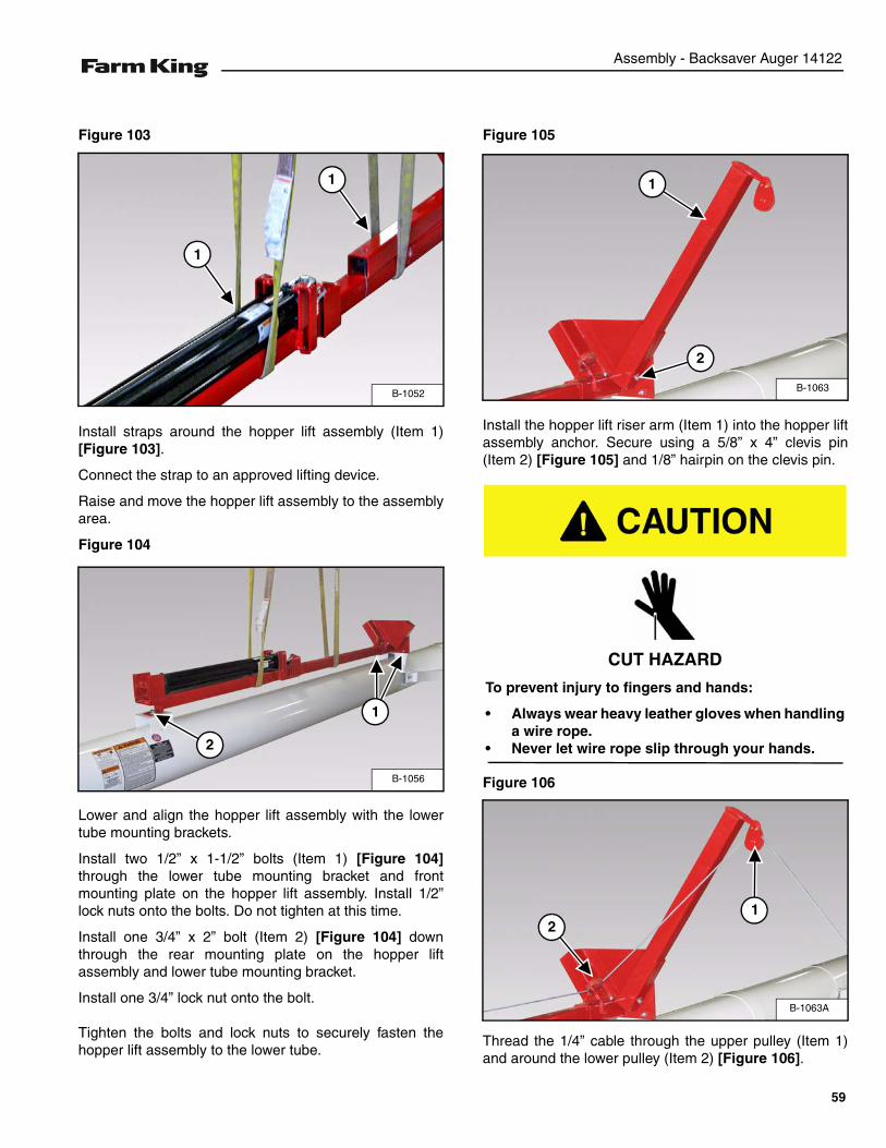
Figure 105
Install the hopper lift riser arm (Item 1) into the hopper liftassembly anchor. Secure using a 5/8” x 4” clevis pin(Item 2) [Figure 105] and 1/8” hairpin on the clevis pin.
Figure 106
Thread the 1/4” cable through the upper pulley (Item 1)and around the lower pulley (Item 2) [Figure 106].
B-1052
1
1
B-1056
2
1
B-1063
1
2
CUT HAZARD
To prevent injury to fingers and hands:
• Always wear heavy leather gloves when handlinga wire rope.
• Never let wire rope slip through your hands.
B-1063A
12
59
Assembly - Backsaver Auger 14122
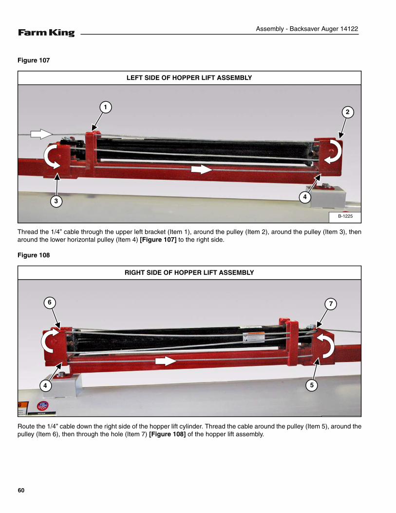
Figure 107
Thread the 1/4” cable through the upper left bracket (Item 1), around the pulley (Item 2), around the pulley (Item 3), thenaround the lower horizontal pulley (Item 4) [Figure 107] to the right side.
Figure 108
Route the 1/4” cable down the right side of the hopper lift cylinder. Thread the cable around the pulley (Item 5), around thepulley (Item 6), then through the hole (Item 7) [Figure 108] of the hopper lift assembly.
B-1225
1
LEFT SIDE OF HOPPER LIFT ASSEMBLY
2
34
7
RIGHT SIDE OF HOPPER LIFT ASSEMBLY
5
6
4
60
Assembly - Backsaver Auger 14122
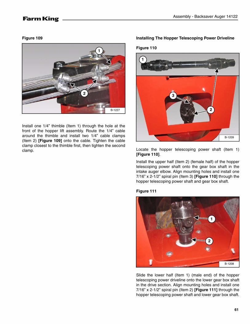
Figure 109
Install one 1/4” thimble (Item 1) through the hole at thefront of the hopper lift assembly. Route the 1/4” cablearound the thimble and install two 1/4” cable clamps(Item 2) [Figure 109] onto the cable. Tighten the cableclamp closest to the thimble first, then tighten the secondclamp.
Installing The Hopper Telescoping Power Driveline
Figure 110
Locate the hopper telescoping power shaft (Item 1)[Figure 110].
Install the upper half (Item 2) (female half) of the hoppertelescoping power shaft onto the gear box shaft in theintake auger elbow. Align mounting holes and install one7/16” x 2-1/2” spiral pin (Item 3) [Figure 110] through thehopper telescoping power shaft and gear box shaft.
Figure 111
Slide the lower half (Item 1) (male end) of the hoppertelescoping power driveline onto the lower gear box shaftin the drive section. Align mounting holes and install one7/16” x 2-1/2” spiral pin (Item 2) [Figure 111] through thehopper telescoping power shaft and lower gear box shaft.
B-1227
1
2
B-1209
1
2
3
B-1208
1
2
61
Assembly - Backsaver Auger 14122
Hopper Assembly And Installation
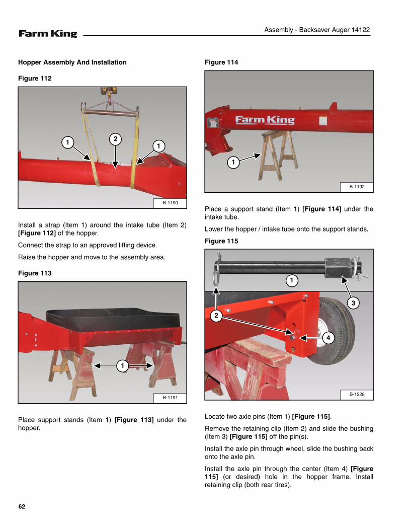
Figure 112
Install a strap (Item 1) around the intake tube (Item 2)[Figure 112] of the hopper.
Connect the strap to an approved lifting device.
Raise the hopper and move to the assembly area.
Figure 113
Place support stands (Item 1) [Figure 113] under thehopper.
Figure 114
Place a support stand (Item 1) [Figure 114] under theintake tube.
Lower the hopper / intake tube onto the support stands.
Figure 115
Locate two axle pins (Item 1) [Figure 115].
Remove the retaining clip (Item 2) and slide the bushing(Item 3) [Figure 115] off the pin(s).
Install the axle pin through wheel, slide the bushing backonto the axle pin.
Install the axle pin through the center (Item 4) [Figure115] (or desired) hole in the hopper frame. Installretaining clip (both rear tires).
B-1190
1 12
B-1191
1
B-1192
1
B-1228
1
3
4
2
62
Assembly - Backsaver Auger 14122
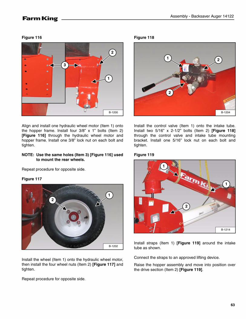
Figure 116
Align and install one hydraulic wheel motor (Item 1) ontothe hopper frame. Install four 3/8” x 1” bolts (Item 2)[Figure 116] through the hydraulic wheel motor andhopper frame. Install one 3/8” lock nut on each bolt andtighten.
NOTE: Use the same holes (Item 3) [Figure 116] usedto mount the rear wheels.
Repeat procedure for opposite side.
Figure 117
Install the wheel (Item 1) onto the hydraulic wheel motor,then install the four wheel nuts (Item 2) [Figure 117] andtighten.
Repeat procedure for opposite side.
Figure 118
Install the control valve (Item 1) onto the intake tube.Install two 5/16” x 2-1/2” bolts (Item 2) [Figure 118]through the control valve and intake tube mountingbracket. Install one 5/16” lock nut on each bolt andtighten.
Figure 119
Install straps (Item 1) [Figure 119] around the intaketube as shown.
Connect the straps to an approved lifting device.
Raise the hopper assembly and move into position overthe drive section (Item 2) [Figure 119].
B-1200
1
3
2
B-1202
12
B-1204
1
2
2
B-1214
1
1
2
63
Assembly - Backsaver Auger 14122
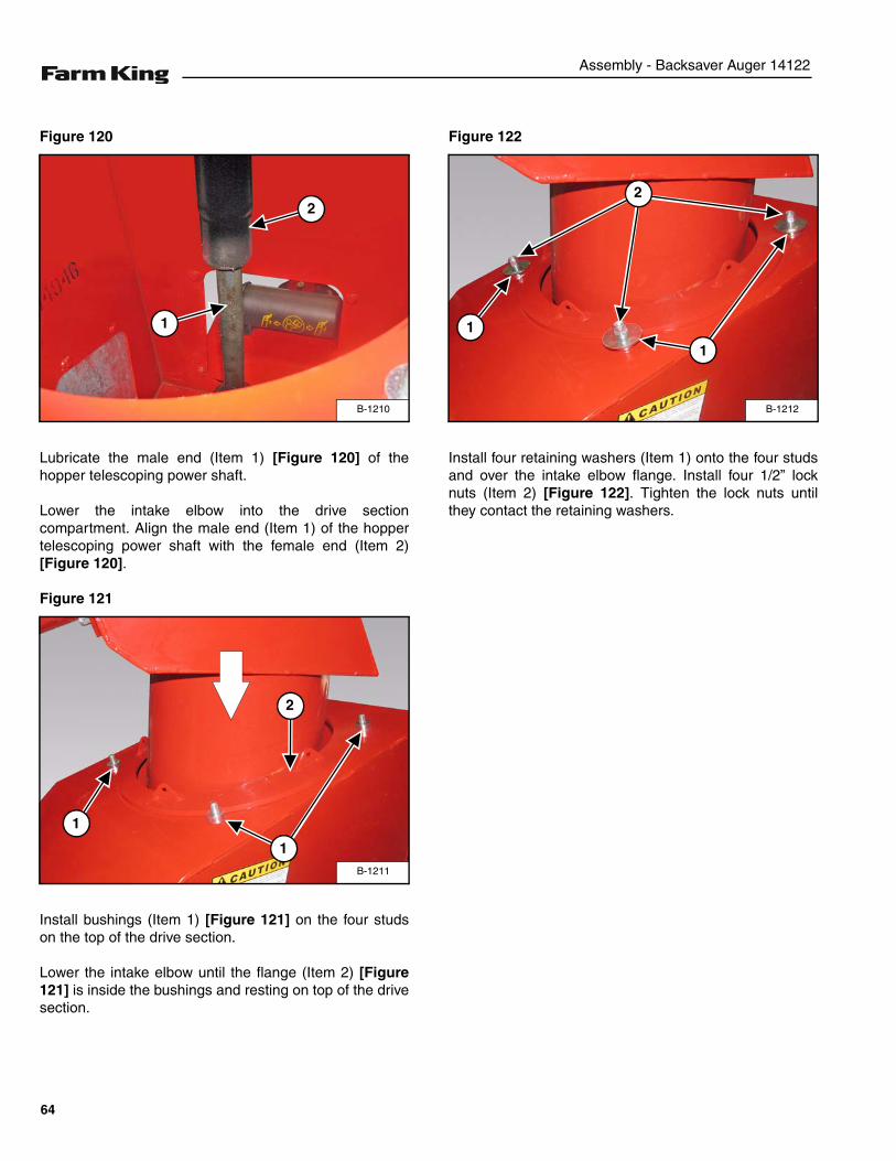
Figure 120
Lubricate the male end (Item 1) [Figure 120] of thehopper telescoping power shaft.
Lower the intake elbow into the drive sectioncompartment. Align the male end (Item 1) of the hoppertelescoping power shaft with the female end (Item 2)[Figure 120].
Figure 121
Install bushings (Item 1) [Figure 121] on the four studson the top of the drive section.
Lower the intake elbow until the flange (Item 2) [Figure121] is inside the bushings and resting on top of the drivesection.
Figure 122
Install four retaining washers (Item 1) onto the four studsand over the intake elbow flange. Install four 1/2” locknuts (Item 2) [Figure 122]. Tighten the lock nuts untilthey contact the retaining washers.
B-1210
2
1
B-1211
2
1
1
B-1212
1
1
2
64
Assembly - Backsaver Auger 14122
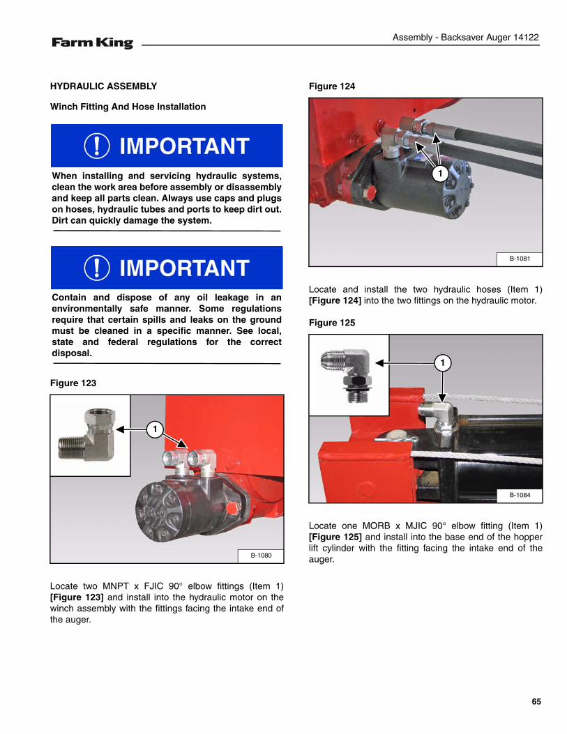
HYDRAULIC ASSEMBLY
Winch Fitting And Hose Installation
Figure 123
Locate two MNPT x FJIC 90° elbow fittings (Item 1)[Figure 123] and install into the hydraulic motor on thewinch assembly with the fittings facing the intake end ofthe auger.
Figure 124
Locate and install the two hydraulic hoses (Item 1)[Figure 124] into the two fittings on the hydraulic motor.
Figure 125
Locate one MORB x MJIC 90° elbow fitting (Item 1)[Figure 125] and install into the base end of the hopperlift cylinder with the fitting facing the intake end of theauger.
When installing and servicing hydraulic systems,clean the work area before assembly or disassemblyand keep all parts clean. Always use caps and plugson hoses, hydraulic tubes and ports to keep dirt out.Dirt can quickly damage the system.
Contain and dispose of any oil leakage in anenvironmentally safe manner. Some regulationsrequire that certain spills and leaks on the groundmust be cleaned in a specific manner. See local,state and federal regulations for the correctdisposal.
B-1080
1
B-1081
1
B-1084
1
65
Assembly - Backsaver Auger 14122
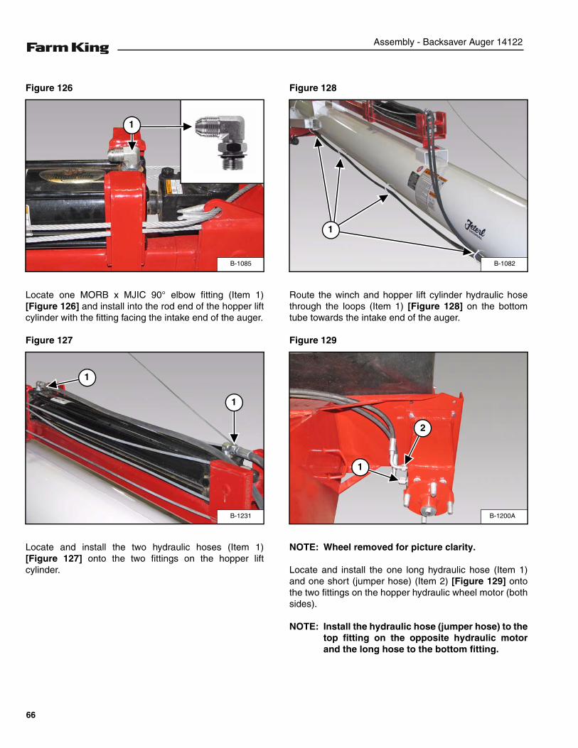
Figure 126
Locate one MORB x MJIC 90° elbow fitting (Item 1)[Figure 126] and install into the rod end of the hopper liftcylinder with the fitting facing the intake end of the auger.
Figure 127
Locate and install the two hydraulic hoses (Item 1)[Figure 127] onto the two fittings on the hopper liftcylinder.
Figure 128
Route the winch and hopper lift cylinder hydraulic hosethrough the loops (Item 1) [Figure 128] on the bottomtube towards the intake end of the auger.
Figure 129
NOTE: Wheel removed for picture clarity.
Locate and install the one long hydraulic hose (Item 1)and one short (jumper hose) (Item 2) [Figure 129] ontothe two fittings on the hopper hydraulic wheel motor (bothsides).
NOTE: Install the hydraulic hose (jumper hose) to thetop fitting on the opposite hydraulic motorand the long hose to the bottom fitting.
B-1085
1
B-1231
1
1
B-1082
1
B-1200A
1
2
66
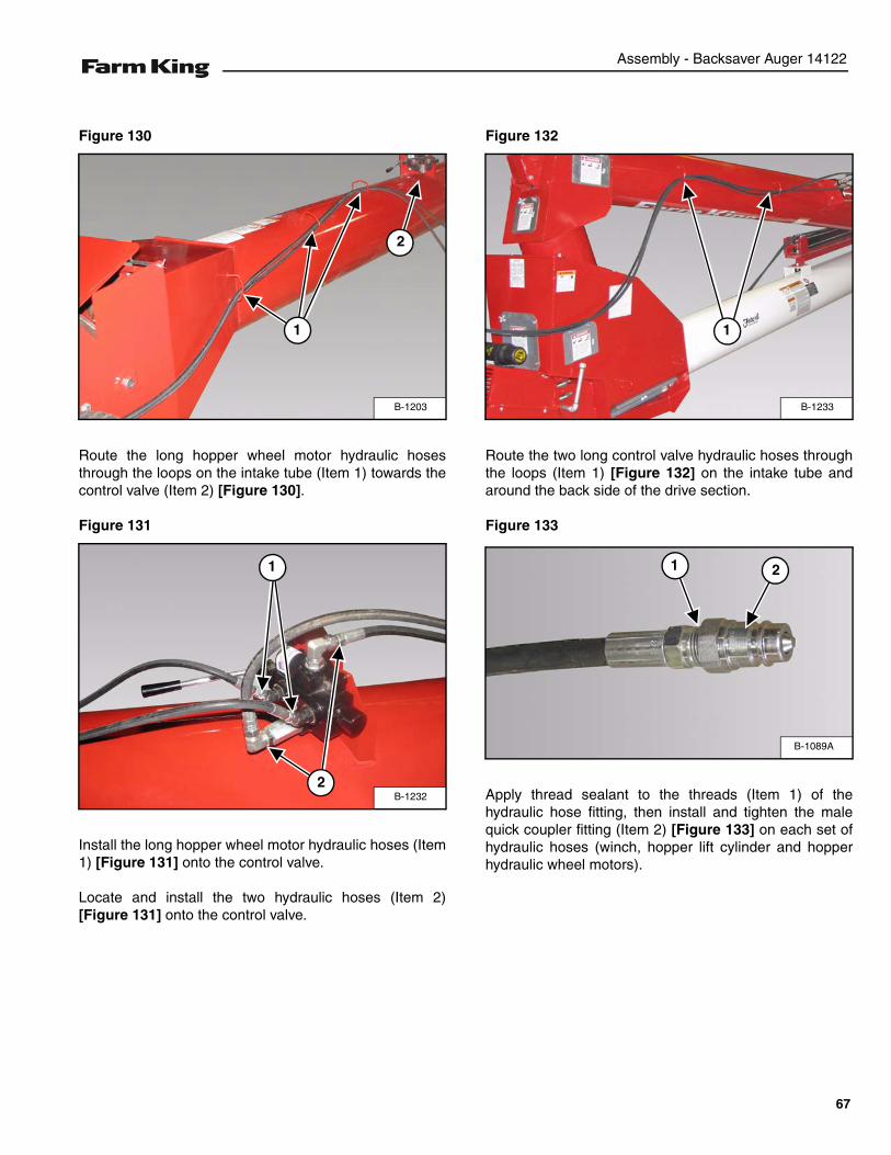
Assembly - Backsaver Auger 14122
Figure 130
Route the long hopper wheel motor hydraulic hosesthrough the loops on the intake tube (Item 1) towards thecontrol valve (Item 2) [Figure 130].
Figure 131
Install the long hopper wheel motor hydraulic hoses (Item1) [Figure 131] onto the control valve.
Locate and install the two hydraulic hoses (Item 2)[Figure 131] onto the control valve.
Figure 132
Route the two long control valve hydraulic hoses throughthe loops (Item 1) [Figure 132] on the intake tube andaround the back side of the drive section.
Figure 133
Apply thread sealant to the threads (Item 1) of thehydraulic hose fitting, then install and tighten the malequick coupler fitting (Item 2) [Figure 133] on each set ofhydraulic hoses (winch, hopper lift cylinder and hopperhydraulic wheel motors).
B-1203
1
2
B-1232
1
2
B-1233
1
B-1089A
21
67
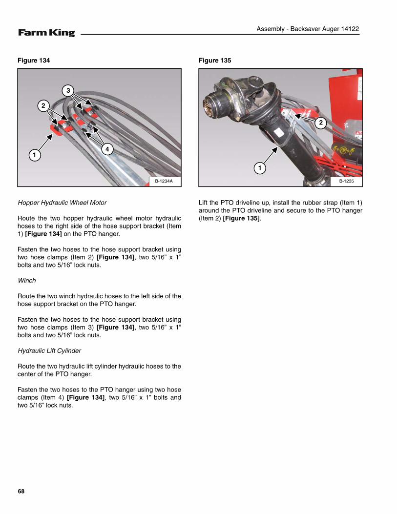
Assembly - Backsaver Auger 14122
Figure 134
Hopper Hydraulic Wheel Motor
Route the two hopper hydraulic wheel motor hydraulichoses to the right side of the hose support bracket (Item1) [Figure 134] on the PTO hanger.
Fasten the two hoses to the hose support bracket usingtwo hose clamps (Item 2) [Figure 134], two 5/16” x 1”bolts and two 5/16” lock nuts.
Winch
Route the two winch hydraulic hoses to the left side of thehose support bracket on the PTO hanger.
Fasten the two hoses to the hose support bracket usingtwo hose clamps (Item 3) [Figure 134], two 5/16” x 1”bolts and two 5/16” lock nuts.
Hydraulic Lift Cylinder
Route the two hydraulic lift cylinder hydraulic hoses to thecenter of the PTO hanger.
Fasten the two hoses to the PTO hanger using two hoseclamps (Item 4) [Figure 134], two 5/16” x 1” bolts andtwo 5/16” lock nuts.
Figure 135
Lift the PTO driveline up, install the rubber strap (Item 1)around the PTO driveline and secure to the PTO hanger(Item 2) [Figure 135].
B-1234A
1
2
3
4
B-1235
1
2
68
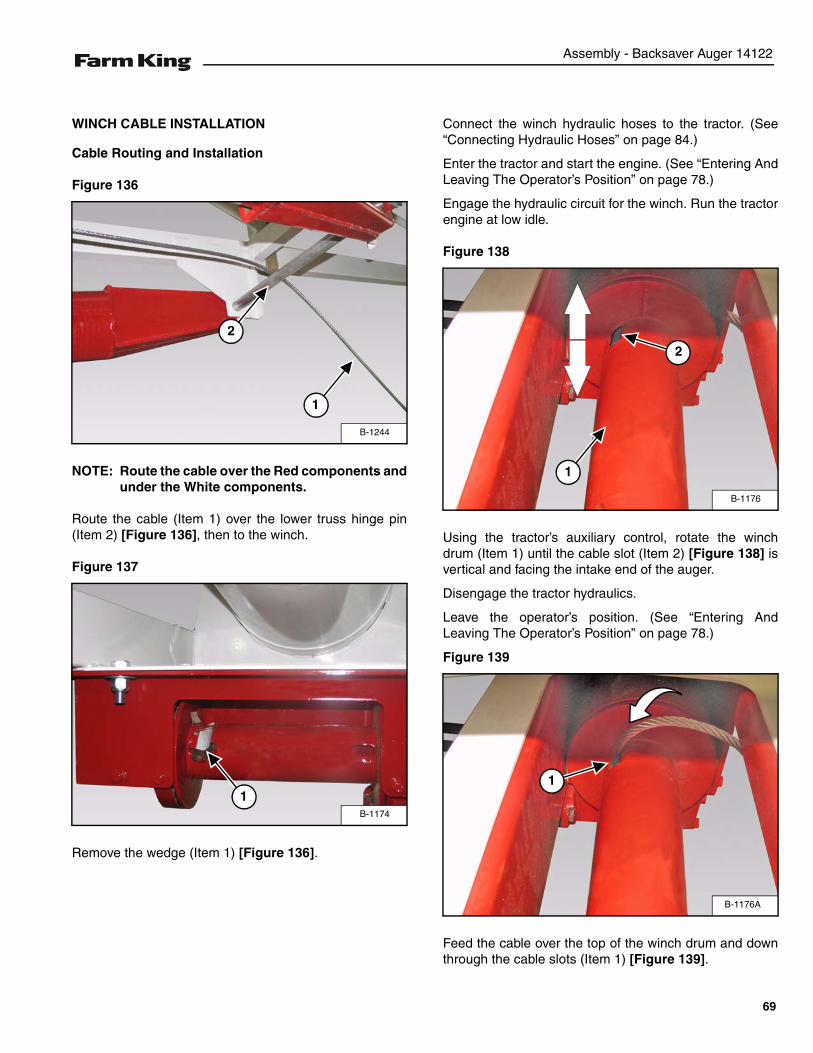
Assembly - Backsaver Auger 14122
WINCH CABLE INSTALLATION
Cable Routing and Installation
Figure 136
NOTE: Route the cable over the Red components andunder the White components.
Route the cable (Item 1) over the lower truss hinge pin(Item 2) [Figure 136], then to the winch.
Figure 137
Remove the wedge (Item 1) [Figure 136].
Connect the winch hydraulic hoses to the tractor. (See“Connecting Hydraulic Hoses” on page 84.)
Enter the tractor and start the engine. (See “Entering AndLeaving The Operator’s Position” on page 78.)
Engage the hydraulic circuit for the winch. Run the tractorengine at low idle.
Figure 138
Using the tractor’s auxiliary control, rotate the winchdrum (Item 1) until the cable slot (Item 2) [Figure 138] isvertical and facing the intake end of the auger.
Disengage the tractor hydraulics.
Leave the operator’s position. (See “Entering AndLeaving The Operator’s Position” on page 78.)
Figure 139
Feed the cable over the top of the winch drum and downthrough the cable slots (Item 1) [Figure 139].
B-1244
1
2
B-1174
1
B-1176
1
2
B-1176A
1
69
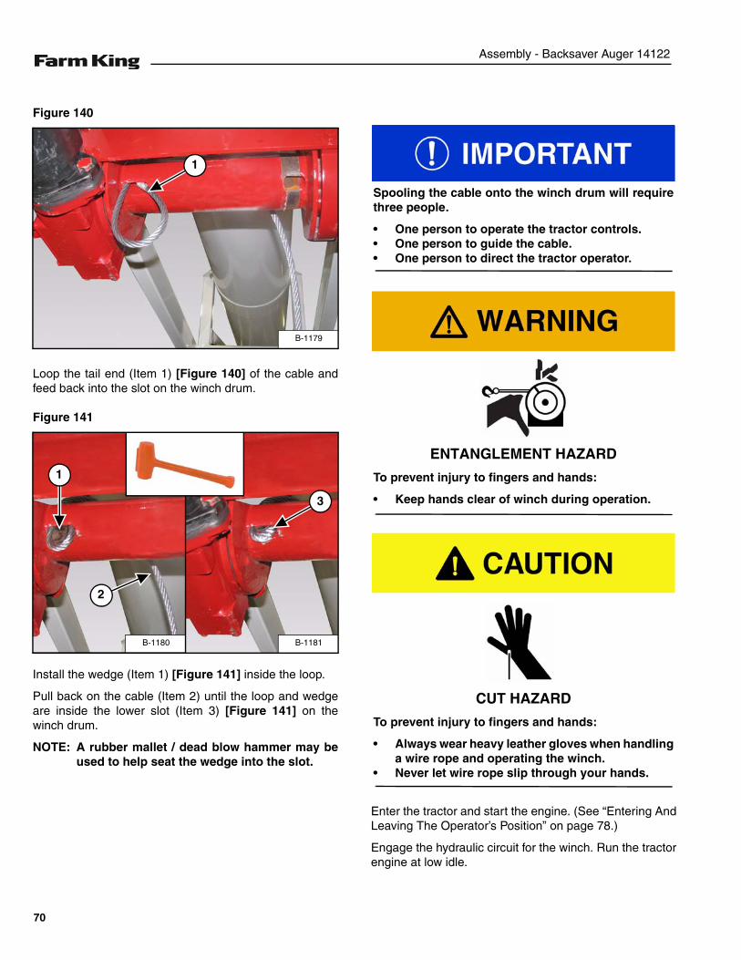
Assembly - Backsaver Auger 14122
Figure 140
Loop the tail end (Item 1) [Figure 140] of the cable andfeed back into the slot on the winch drum.
Figure 141
Install the wedge (Item 1) [Figure 141] inside the loop.
Pull back on the cable (Item 2) until the loop and wedgeare inside the lower slot (Item 3) [Figure 141] on thewinch drum.
NOTE: A rubber mallet / dead blow hammer may beused to help seat the wedge into the slot.
Enter the tractor and start the engine. (See “Entering AndLeaving The Operator’s Position” on page 78.)
Engage the hydraulic circuit for the winch. Run the tractorengine at low idle.
B-1179
1
B-1181
3
B-1180
1
2
Spooling the cable onto the winch drum will requirethree people.
• One person to operate the tractor controls.• One person to guide the cable.• One person to direct the tractor operator.
ENTANGLEMENT HAZARD
To prevent injury to fingers and hands:
• Keep hands clear of winch during operation.
CUT HAZARD
To prevent injury to fingers and hands:
• Always wear heavy leather gloves when handlinga wire rope and operating the winch.
• Never let wire rope slip through your hands.
70
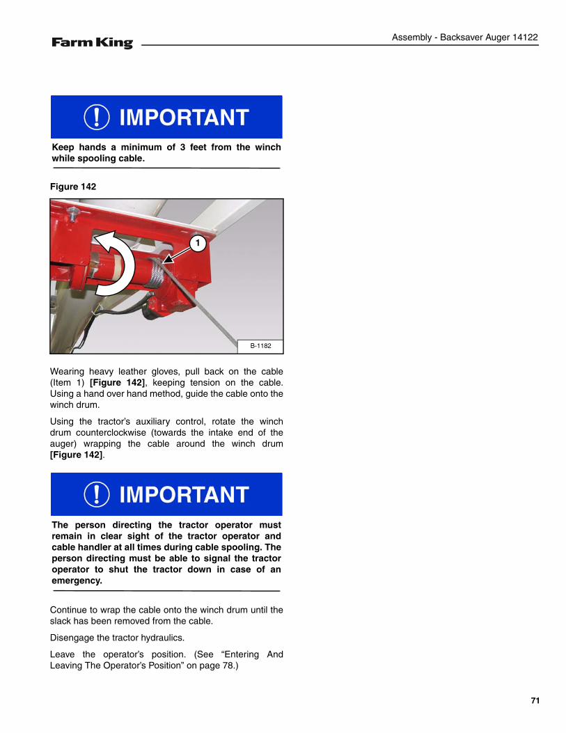
Assembly - Backsaver Auger 14122
Figure 142
Wearing heavy leather gloves, pull back on the cable(Item 1) [Figure 142], keeping tension on the cable.Using a hand over hand method, guide the cable onto thewinch drum.
Using the tractor’s auxiliary control, rotate the winchdrum counterclockwise (towards the intake end of theauger) wrapping the cable around the winch drum[Figure 142].
Continue to wrap the cable onto the winch drum until theslack has been removed from the cable.
Disengage the tractor hydraulics.
Leave the operator’s position. (See “Entering AndLeaving The Operator’s Position” on page 78.)
Keep hands a minimum of 3 feet from the winchwhile spooling cable.
B-1182
1
The person directing the tractor operator mustremain in clear sight of the tractor operator andcable handler at all times during cable spooling. Theperson directing must be able to signal the tractoroperator to shut the tractor down in case of anemergency.
71

Assembly - Backsaver Auger 14122
72
Operation - Backsaver Auger 14122
OPERATION
GENERAL OPERATION INFORMATION . . . . . . . . . . . . . . . . . . . . . . . . . . . . . . . . . . . . . . . . . . . . . 75Pre - Operation Checklist . . . . . . . . . . . . . . . . . . . . . . . . . . . . . . . . . . . . . . . . . . . . . . . . . . . . . . 75Break - In Checklist . . . . . . . . . . . . . . . . . . . . . . . . . . . . . . . . . . . . . . . . . . . . . . . . . . . . . . . . . . . 76Tractor Requirements . . . . . . . . . . . . . . . . . . . . . . . . . . . . . . . . . . . . . . . . . . . . . . . . . . . . . . . . . 77Entering And Leaving The Operator’s Position . . . . . . . . . . . . . . . . . . . . . . . . . . . . . . . . . . . . . . 78
INITIAL SET-UP . . . . . . . . . . . . . . . . . . . . . . . . . . . . . . . . . . . . . . . . . . . . . . . . . . . . . . . . . . . . . . . . 79Connecting The Backsaver Auger To The Tractor . . . . . . . . . . . . . . . . . . . . . . . . . . . . . . . . . . . . 79Connecting The PTO Driveline . . . . . . . . . . . . . . . . . . . . . . . . . . . . . . . . . . . . . . . . . . . . . . . . . . 80PTO Driveline . . . . . . . . . . . . . . . . . . . . . . . . . . . . . . . . . . . . . . . . . . . . . . . . . . . . . . . . . . . . . . .81Connecting Hydraulic Hoses . . . . . . . . . . . . . . . . . . . . . . . . . . . . . . . . . . . . . . . . . . . . . . . . . . . . 84Axle Extension Installation . . . . . . . . . . . . . . . . . . . . . . . . . . . . . . . . . . . . . . . . . . . . . . . . . . . . . 85
AUGER OPERATION . . . . . . . . . . . . . . . . . . . . . . . . . . . . . . . . . . . . . . . . . . . . . . . . . . . . . . . . . . . .87Lowering And Raising The Hopper . . . . . . . . . . . . . . . . . . . . . . . . . . . . . . . . . . . . . . . . . . . . . . . 87Hydraulic Hopper Mover Operation . . . . . . . . . . . . . . . . . . . . . . . . . . . . . . . . . . . . . . . . . . . . . . . 89Raising The Auger . . . . . . . . . . . . . . . . . . . . . . . . . . . . . . . . . . . . . . . . . . . . . . . . . . . . . . . . . . . 90Auger Placement . . . . . . . . . . . . . . . . . . . . . . . . . . . . . . . . . . . . . . . . . . . . . . . . . . . . . . . . . . . . 92Lowering The Auger . . . . . . . . . . . . . . . . . . . . . . . . . . . . . . . . . . . . . . . . . . . . . . . . . . . . . . . . . . 94
LOADING GRAIN INTO THE HOPPER . . . . . . . . . . . . . . . . . . . . . . . . . . . . . . . . . . . . . . . . . . . . . .95Unloading Belly Dump Units . . . . . . . . . . . . . . . . . . . . . . . . . . . . . . . . . . . . . . . . . . . . . . . . . . . . 95Unloading Rear And Side Dump Units . . . . . . . . . . . . . . . . . . . . . . . . . . . . . . . . . . . . . . . . . . . . 97
TRANSPORTING . . . . . . . . . . . . . . . . . . . . . . . . . . . . . . . . . . . . . . . . . . . . . . . . . . . . . . . . . . . . . . . 99Requirements . . . . . . . . . . . . . . . . . . . . . . . . . . . . . . . . . . . . . . . . . . . . . . . . . . . . . . . . . . . . . . .99Transporting Guidelines . . . . . . . . . . . . . . . . . . . . . . . . . . . . . . . . . . . . . . . . . . . . . . . . . . . . . . . 99Transporting Procedure . . . . . . . . . . . . . . . . . . . . . . . . . . . . . . . . . . . . . . . . . . . . . . . . . . . . . . 100
73

Operation - Backsaver Auger 14122
74
Operation - Backsaver Auger 14122
GENERAL OPERATION INFORMATION
Pre - Operation Checklist
Before operating the Backsaver Auger for the first timeand each time thereafter, check the following items:
1. Lubricate the equipment per the schedule outline inthe Maintenance Section. (See “SERVICESCHEDULE” on page 108.)
2. Check the auger hitch for damaged, loose or missingparts. Repair as needed before operation.
3. Check tire pressure. Inflate per manufacturer’sspecification.
4. Check wheel bolts for tightness. Torque as required.(See “AXLE” on page 114.)
5. Check the augers. Remove any material build-up ordebris that has become entangled.
6. Check that all bearings turn freely. Replace asrequired.
7. Make sure that all guards and shields are in place,secured and functioning as designed.
8. Check condition of all hydraulic components for leaks.Repair as required.
NOTE: Do not operate with hydraulic leaks.
9. Check gearbox oil level. Fill as required. (See“LUBRICATION” on page 109.)
10. Verify that the tractor’s drawbar is adjusted correctlyfor use with the auger. (See “Drawbar Adjustment” onpage 77.)
11. Check that the PTO drivelines telescope easily andturn freely.
12. Make sure the PTO ends are securely attached to theauger and the tractor.
AVOID INJURY OR DEATH
• Disengage the PTO, engage the machine’sparking brake, stop the engine and make sure allrotating components are completely stoppedbefore connecting, disconnecting, adjusting orcleaning any PTO driven equipment.
• Always keep PTO shields and all guards in placewhen using PTO driven equipment.
• Disengage PTO for road travel.
• Keep hands, feet and clothing away.
AVOID INJURY OR DEATH
Wear safety glasses to prevent eye injury when anyof the following conditions exist:
• When fluids are under pressure.
• Flying debris or loose material is present.
• Engine is running.
• Tools are being used.
Leaking fluids under pressure can enter the skinand cause serious injury or death. Immediatemedical attention is required. Wear goggles. Usecardboard to check for leaks.
75
Operation - Backsaver Auger 14122
Break - In Checklist
NOTE: The Backsaver Auger must have a break-inperiod with different operating conditionsthan for normal use.
The tube and flighting must get a polished surfacethrough use. Once the new auger has polished it will runsmooth at recommended speed.
NOTE: Never operate an empty auger for over oneminute, as the flighting and housing willexperience excessive wear.
During the break-in-period:
1. Run the tractor at slow idle until grain begins to flowfrom the discharge. For the first 500 bushels, operateat the slow speed and restrict the flow of grain at theintake.
2. Gradually increase the speed until operating at fullPTO speed.
NOTE: Do not run empty during break-in period.
Check the following mechanical items after 1 hour ofoperation and again after 10 hours of operation:
1. Check the auger hitch for damaged, loose or missingparts. Repair as needed before operation.
2. Check for loose fasteners and hardware. Tighten asrequired.
3. Make sure that all guards and shields are in place,secured and functioning as designed
4. Check that the PTO driveline telescopes easily andturns freely.
5. Check condition of all hydraulic components for leaks.Tighten fittings to correct leaks or replacecomponents. Do not operate with hydraulic leaks.
6. Check tire pressure. Inflate per manufacturer’sspecification.
7. Check gearbox oil level. Fill as required. (See“LUBRICATION” on page 109.)
8. Check the augers. Remove any debris.
AVOID INJURY OR DEATH
• Disengage the PTO, engage the machine’sparking brake, stop the engine and make sure allrotating components are completely stoppedbefore connecting, disconnecting, adjusting orcleaning any PTO driven equipment.
• Always keep PTO shields and all guards in placewhen using PTO driven equipment.
• Disengage PTO for road travel.
• Keep hands, feet and clothing away.
76
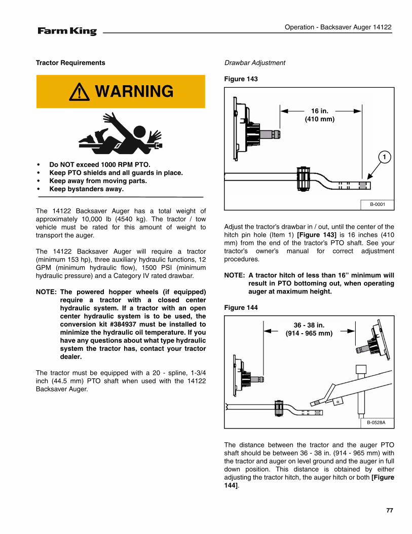
Operation - Backsaver Auger 14122
Tractor Requirements
The 14122 Backsaver Auger has a total weight ofapproximately 10,000 lb (4540 kg). The tractor / towvehicle must be rated for this amount of weight totransport the auger.
The 14122 Backsaver Auger will require a tractor(minimum 153 hp), three auxiliary hydraulic functions, 12GPM (minimum hydraulic flow), 1500 PSI (minimumhydraulic pressure) and a Category IV rated drawbar.
NOTE: The powered hopper wheels (if equipped)require a tractor with a closed centerhydraulic system. If a tractor with an opencenter hydraulic system is to be used, theconversion kit #384937 must be installed tominimize the hydraulic oil temperature. If youhave any questions about what type hydraulicsystem the tractor has, contact your tractordealer.
The tractor must be equipped with a 20 - spline, 1-3/4inch (44.5 mm) PTO shaft when used with the 14122Backsaver Auger.
Drawbar Adjustment
Figure 143
Adjust the tractor’s drawbar in / out, until the center of thehitch pin hole (Item 1) [Figure 143] is 16 inches (410mm) from the end of the tractor’s PTO shaft. See yourtractor’s owner’s manual for correct adjustmentprocedures.
NOTE: A tractor hitch of less than 16” minimum willresult in PTO bottoming out, when operatingauger at maximum height.
Figure 144
The distance between the tractor and the auger PTOshaft should be between 36 - 38 in. (914 - 965 mm) withthe tractor and auger on level ground and the auger in fulldown position. This distance is obtained by eitheradjusting the tractor hitch, the auger hitch or both [Figure144].
• Do NOT exceed 1000 RPM PTO.• Keep PTO shields and all guards in place.• Keep away from moving parts.• Keep bystanders away.
B-0001
16 in.(410 mm)
1
B-0528A
36 - 38 in.(914 - 965 mm)
77
Operation - Backsaver Auger 14122
Entering And Leaving The Operator’s Position
Entering The Operator’s Position
Move to the operator’s position, start the engine andrelease the parking brake.
Leaving The Operator’s Position
Park the tractor / equipment on a flat level surface.
Place all controls in neutral, engage the park brake, stopthe engine and wait for all moving parts to stop. Leavethe operator’s position.
Follow the instructions in your tractor’s operationmanual for the correct procedure.
AVOID INJURY OR DEATHBefore you leave the operator’s position:• Always park on a flat level surface.• Place all controls in NEUTRAL.• Engage the park brake.• Stop the engine and remove the key.• Wait for all moving parts to stop.
78
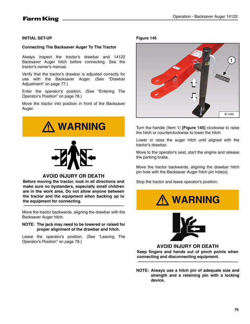
Operation - Backsaver Auger 14122
INITIAL SET-UP
Connecting The Backsaver Auger To The Tractor
Always inspect the tractor’s drawbar and 14122Backsaver Auger hitch before connecting. See thetractor’s owner’s manual.
Verify that the tractor’s drawbar is adjusted correctly foruse with the Backsaver Auger. (See “DrawbarAdjustment” on page 77.)
Enter the operator’s position. (See “Entering TheOperator’s Position” on page 78.)
Move the tractor into position in front of the BacksaverAuger.
Move the tractor backwards, aligning the drawbar with theBacksaver Auger hitch.
NOTE: The jack may need to be lowered or raised forproper alignment of the drawbar and hitch.
Leave the operator’s position. (See “Leaving TheOperator’s Position” on page 78.)
Figure 145
Turn the handle (Item 1) [Figure 145] clockwise to raisethe hitch or counterclockwise to lower the hitch.
Lower or raise the auger hitch until aligned with thetractor’s drawbar.
Move to the operator’s seat, start the engine and releasethe parking brake.
Move the tractor backwards, aligning the drawbar hitchpin hole with the Backsaver Auger hitch pin hole(s).
Stop the tractor and leave operator’s position.
NOTE: Always use a hitch pin of adequate size andstrength and a retaining pin with a lockingdevice.
AVOID INJURY OR DEATHBefore moving the tractor, look in all directions andmake sure no bystanders, especially small childrenare in the work area. Do not allow anyone betweenthe tractor and the equipment when backing up tothe equipment for connecting.
B-1042
1
AVOID INJURY OR DEATHKeep fingers and hands out of pinch points whenconnecting and disconnecting equipment.
79
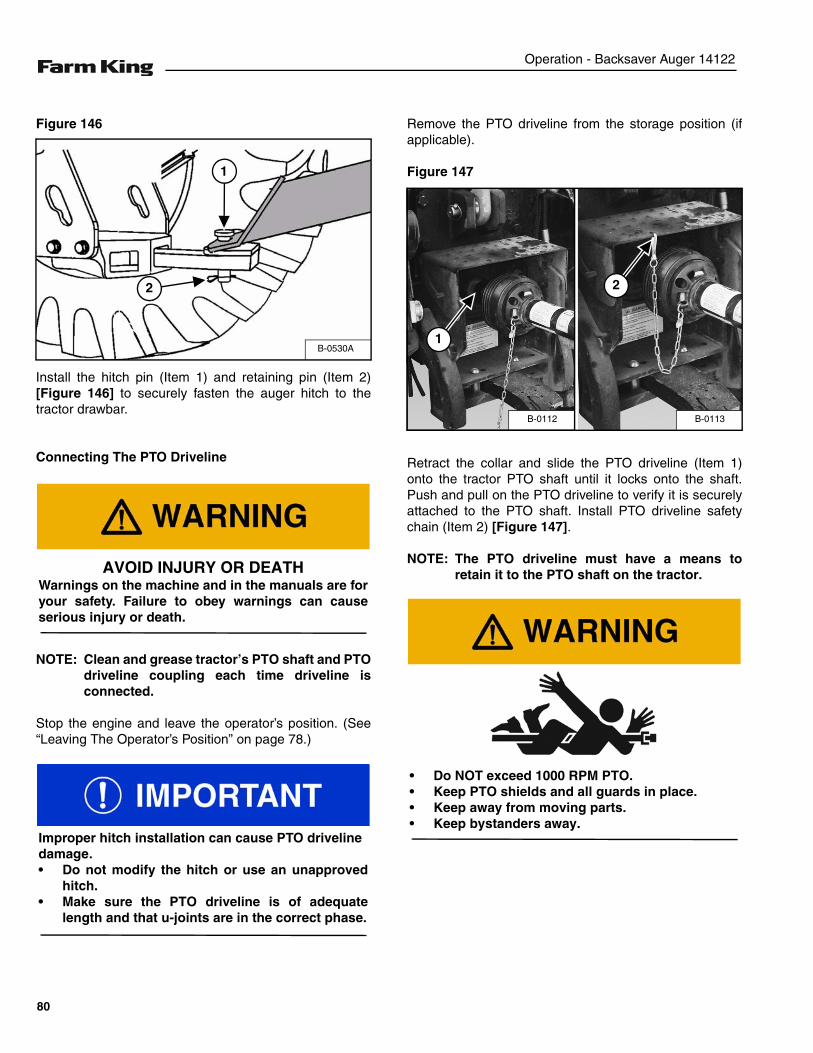
Operation - Backsaver Auger 14122
Figure 146
Install the hitch pin (Item 1) and retaining pin (Item 2)[Figure 146] to securely fasten the auger hitch to thetractor drawbar.
Connecting The PTO Driveline
NOTE: Clean and grease tractor’s PTO shaft and PTOdriveline coupling each time driveline isconnected.
Stop the engine and leave the operator’s position. (See“Leaving The Operator’s Position” on page 78.)
Remove the PTO driveline from the storage position (ifapplicable).
Figure 147
Retract the collar and slide the PTO driveline (Item 1)onto the tractor PTO shaft until it locks onto the shaft.Push and pull on the PTO driveline to verify it is securelyattached to the PTO shaft. Install PTO driveline safetychain (Item 2) [Figure 147].
NOTE: The PTO driveline must have a means toretain it to the PTO shaft on the tractor.
B-0530A
1
2
AVOID INJURY OR DEATHWarnings on the machine and in the manuals are foryour safety. Failure to obey warnings can causeserious injury or death.
Improper hitch installation can cause PTO drivelinedamage.• Do not modify the hitch or use an unapproved
hitch.• Make sure the PTO driveline is of adequate
length and that u-joints are in the correct phase.
B-0113B-0112
1
2
• Do NOT exceed 1000 RPM PTO.• Keep PTO shields and all guards in place.• Keep away from moving parts.• Keep bystanders away.
80
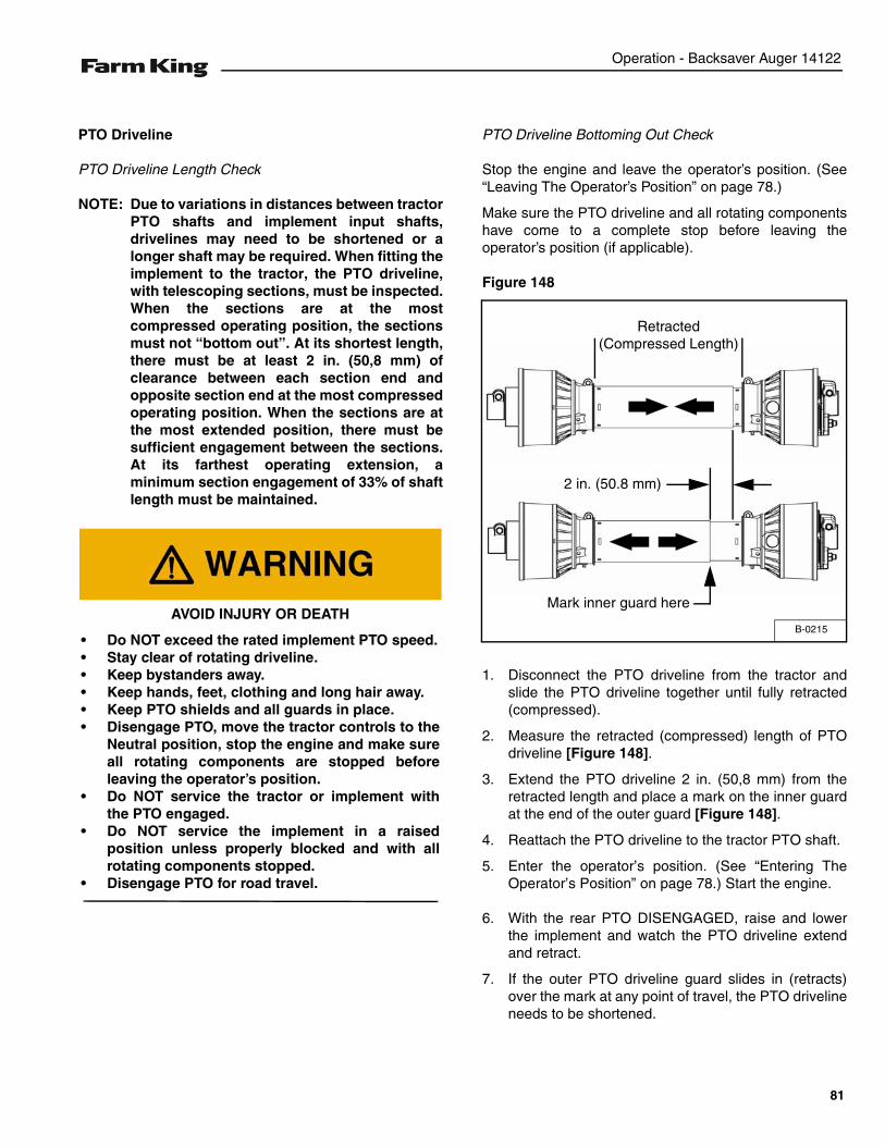
Operation - Backsaver Auger 14122
PTO Driveline
PTO Driveline Length Check
NOTE: Due to variations in distances between tractorPTO shafts and implement input shafts,drivelines may need to be shortened or alonger shaft may be required. When fitting theimplement to the tractor, the PTO driveline,with telescoping sections, must be inspected.When the sections are at the mostcompressed operating position, the sectionsmust not “bottom out”. At its shortest length,there must be at least 2 in. (50,8 mm) ofclearance between each section end andopposite section end at the most compressedoperating position. When the sections are atthe most extended position, there must besufficient engagement between the sections.At its farthest operating extension, aminimum section engagement of 33% of shaftlength must be maintained.
PTO Driveline Bottoming Out Check
Stop the engine and leave the operator’s position. (See“Leaving The Operator’s Position” on page 78.)
Make sure the PTO driveline and all rotating componentshave come to a complete stop before leaving theoperator’s position (if applicable).
Figure 148
1. Disconnect the PTO driveline from the tractor andslide the PTO driveline together until fully retracted(compressed).
2. Measure the retracted (compressed) length of PTOdriveline [Figure 148].
3. Extend the PTO driveline 2 in. (50,8 mm) from theretracted length and place a mark on the inner guardat the end of the outer guard [Figure 148].
4. Reattach the PTO driveline to the tractor PTO shaft.
5. Enter the operator’s position. (See “Entering TheOperator’s Position” on page 78.) Start the engine.
6. With the rear PTO DISENGAGED, raise and lowerthe implement and watch the PTO driveline extendand retract.
7. If the outer PTO driveline guard slides in (retracts)over the mark at any point of travel, the PTO drivelineneeds to be shortened.
AVOID INJURY OR DEATH
• Do NOT exceed the rated implement PTO speed.• Stay clear of rotating driveline.• Keep bystanders away.• Keep hands, feet, clothing and long hair away.• Keep PTO shields and all guards in place.• Disengage PTO, move the tractor controls to the
Neutral position, stop the engine and make sureall rotating components are stopped beforeleaving the operator’s position.
• Do NOT service the tractor or implement withthe PTO engaged.
• Do NOT service the implement in a raisedposition unless properly blocked and with allrotating components stopped.
• Disengage PTO for road travel.
B-0215
Retracted (Compressed Length)
Mark inner guard here
2 in. (50.8 mm)
81
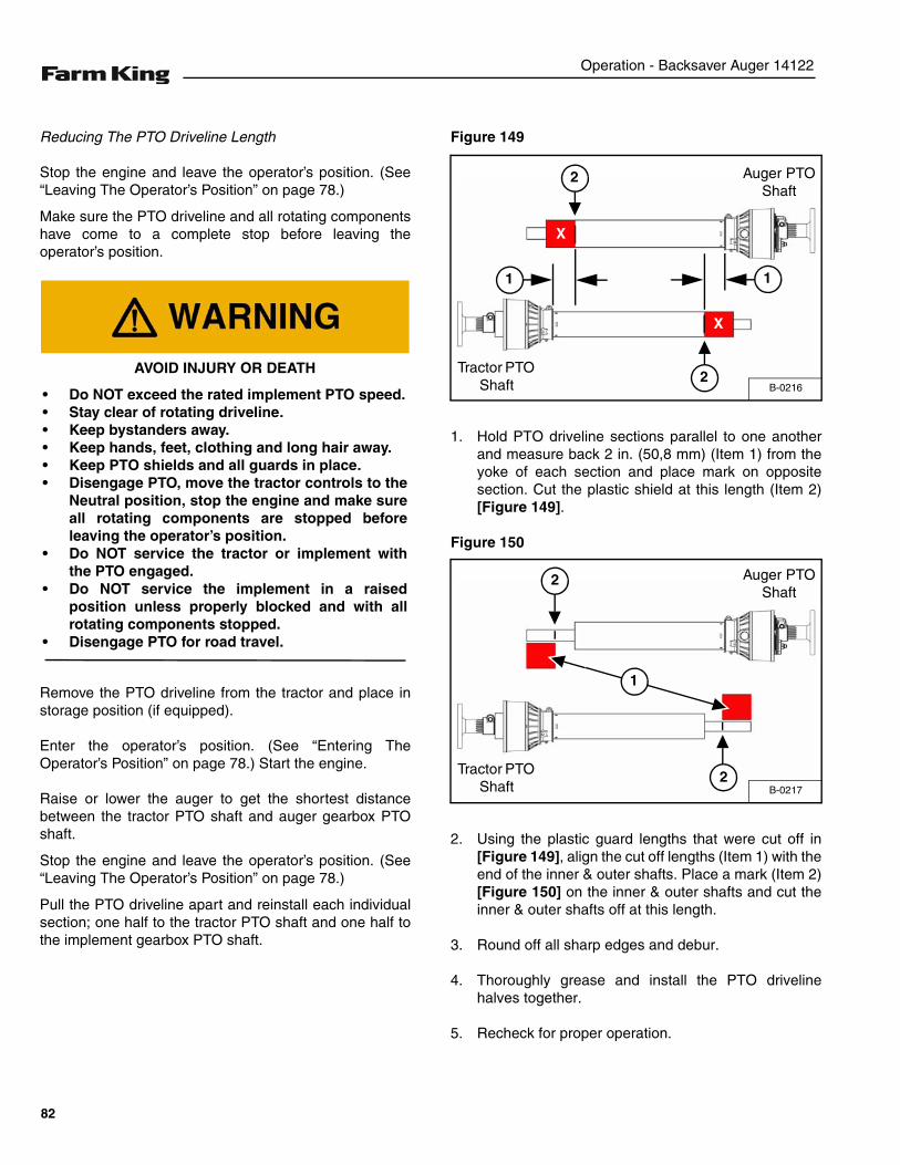
Operation - Backsaver Auger 14122
Reducing The PTO Driveline Length
Stop the engine and leave the operator’s position. (See“Leaving The Operator’s Position” on page 78.)
Make sure the PTO driveline and all rotating componentshave come to a complete stop before leaving theoperator’s position.
Remove the PTO driveline from the tractor and place instorage position (if equipped).
Enter the operator’s position. (See “Entering TheOperator’s Position” on page 78.) Start the engine.
Raise or lower the auger to get the shortest distancebetween the tractor PTO shaft and auger gearbox PTOshaft.
Stop the engine and leave the operator’s position. (See“Leaving The Operator’s Position” on page 78.)
Pull the PTO driveline apart and reinstall each individualsection; one half to the tractor PTO shaft and one half tothe implement gearbox PTO shaft.
Figure 149
1. Hold PTO driveline sections parallel to one anotherand measure back 2 in. (50,8 mm) (Item 1) from theyoke of each section and place mark on oppositesection. Cut the plastic shield at this length (Item 2)[Figure 149].
Figure 150
2. Using the plastic guard lengths that were cut off in[Figure 149], align the cut off lengths (Item 1) with theend of the inner & outer shafts. Place a mark (Item 2)[Figure 150] on the inner & outer shafts and cut theinner & outer shafts off at this length.
3. Round off all sharp edges and debur.
4. Thoroughly grease and install the PTO drivelinehalves together.
5. Recheck for proper operation.
AVOID INJURY OR DEATH
• Do NOT exceed the rated implement PTO speed.• Stay clear of rotating driveline.• Keep bystanders away.• Keep hands, feet, clothing and long hair away.• Keep PTO shields and all guards in place.• Disengage PTO, move the tractor controls to the
Neutral position, stop the engine and make sureall rotating components are stopped beforeleaving the operator’s position.
• Do NOT service the tractor or implement withthe PTO engaged.
• Do NOT service the implement in a raisedposition unless properly blocked and with allrotating components stopped.
• Disengage PTO for road travel.
B-0216
Tractor PTO Shaft
Auger PTO Shaft
X
1
2
2
X
1
B-0217
Tractor PTO Shaft
Auger PTO Shaft
1
2
2
82
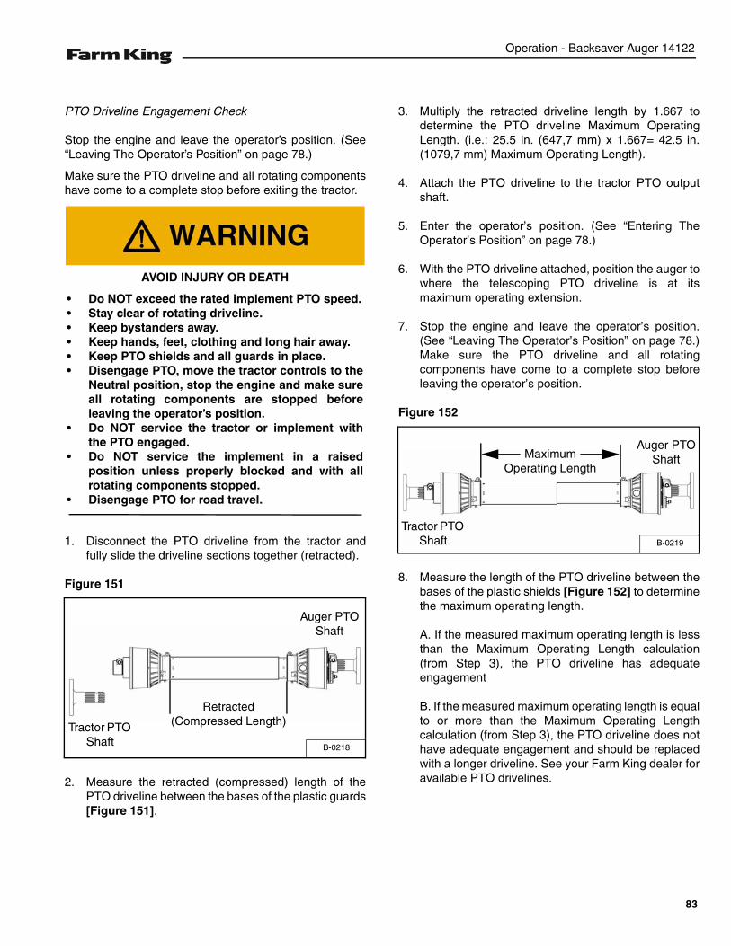
Operation - Backsaver Auger 14122
PTO Driveline Engagement Check
Stop the engine and leave the operator’s position. (See“Leaving The Operator’s Position” on page 78.)
Make sure the PTO driveline and all rotating componentshave come to a complete stop before exiting the tractor.
1. Disconnect the PTO driveline from the tractor andfully slide the driveline sections together (retracted).
Figure 151
2. Measure the retracted (compressed) length of thePTO driveline between the bases of the plastic guards[Figure 151].
3. Multiply the retracted driveline length by 1.667 todetermine the PTO driveline Maximum OperatingLength. (i.e.: 25.5 in. (647,7 mm) x 1.667= 42.5 in.(1079,7 mm) Maximum Operating Length).
4. Attach the PTO driveline to the tractor PTO outputshaft.
5. Enter the operator’s position. (See “Entering TheOperator’s Position” on page 78.)
6. With the PTO driveline attached, position the auger towhere the telescoping PTO driveline is at itsmaximum operating extension.
7. Stop the engine and leave the operator’s position.(See “Leaving The Operator’s Position” on page 78.)Make sure the PTO driveline and all rotatingcomponents have come to a complete stop beforeleaving the operator’s position.
Figure 152
8. Measure the length of the PTO driveline between thebases of the plastic shields [Figure 152] to determinethe maximum operating length.
A. If the measured maximum operating length is lessthan the Maximum Operating Length calculation(from Step 3), the PTO driveline has adequateengagement
B. If the measured maximum operating length is equalto or more than the Maximum Operating Lengthcalculation (from Step 3), the PTO driveline does nothave adequate engagement and should be replacedwith a longer driveline. See your Farm King dealer foravailable PTO drivelines.
AVOID INJURY OR DEATH
• Do NOT exceed the rated implement PTO speed.• Stay clear of rotating driveline.• Keep bystanders away.• Keep hands, feet, clothing and long hair away.• Keep PTO shields and all guards in place.• Disengage PTO, move the tractor controls to the
Neutral position, stop the engine and make sureall rotating components are stopped beforeleaving the operator’s position.
• Do NOT service the tractor or implement withthe PTO engaged.
• Do NOT service the implement in a raisedposition unless properly blocked and with allrotating components stopped.
• Disengage PTO for road travel.
B-0218
Tractor PTO Shaft
Auger PTO Shaft
Retracted (Compressed Length)
B-0219
Maximum Operating Length
Auger PTO Shaft
Tractor PTO Shaft
83
Operation - Backsaver Auger 14122
Connecting Hydraulic Hoses
NOTE: Make sure the quick couplers are fullyengaged. If the quick couplers do not fullyengage, check to see that the couplers are thesame size and type.
To Connect:
Figure 153
Pull back on the collar of the female coupler, pushcouplers together, release the collar when the couplersare fully engaged and locked [Figure 153].
Install the two winch quick coupler hoses (Item 1) [Figure153].
Install the two hopper lift quick coupler hoses (Item 2)[Figure 153].
Install the two hydraulic mover valve block quick couplerhoses (Item 3) [Figure 153].
To Disconnect:
Pull back on the collar and pull the male coupler out todisconnect.
HIGH PRESSURE FLUID HAZARD
To prevent serious injury or death from highpressure fluid:
• Relieve pressure on system before repairing oradjusting.
• Wear proper hand and eye protection whensearching for leaks. Use wood or cardboardinstead of hands.
• Keep all components in good repair.
• Contain and dispose of any oil leakage in anenvironmentally safe manner.
• Thoroughly clean the quick couplers beforemaking connections. Dirt can quickly damagethe system.
B-0531B
1
2
3
AVOID BURNS
Hydraulic fluid, tubes, fittings and quick couplerscan get hot when running equipment. Be carefulwhen connecting and disconnecting quick couplers.
84
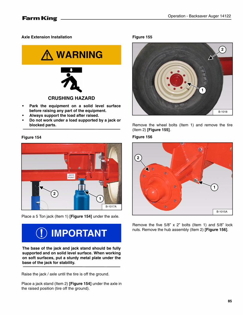
Operation - Backsaver Auger 14122
Axle Extension Installation
Figure 154
Place a 5 Ton jack (Item 1) [Figure 154] under the axle.
Raise the jack / axle until the tire is off the ground.
Place a jack stand (Item 2) [Figure 154] under the axle inthe raised position (tire off the ground).
Figure 155
Remove the wheel bolts (Item 1) and remove the tire(Item 2) [Figure 155].
Figure 156
Remove the five 5/8” x 2” bolts (Item 1) and 5/8” locknuts. Remove the hub assembly (Item 2) [Figure 156].
CRUSHING HAZARD
• Park the equipment on a solid level surfacebefore raising any part of the equipment.
• Always support the load after raised.• Do not work under a load supported by a jack or
blocked parts.
B-1017A
12
The base of the jack and jack stand should be fullysupported and on solid level surface. When workingon soft surfaces, put a sturdy metal plate under thebase of the jack for stability.
B-1018
1
2
B-1015A
2
1
85
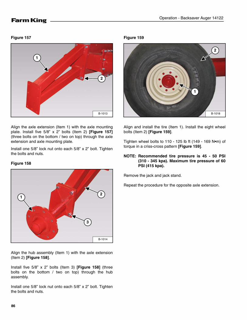
Operation - Backsaver Auger 14122
Figure 157
Align the axle extension (Item 1) with the axle mountingplate. Install five 5/8” x 2” bolts (Item 2) [Figure 157](three bolts on the bottom / two on top) through the axleextension and axle mounting plate.
Install one 5/8” lock nut onto each 5/8” x 2” bolt. Tightenthe bolts and nuts.
Figure 158
Align the hub assembly (Item 1) with the axle extension(Item 2) [Figure 158].
Install five 5/8” x 2” bolts (Item 3) [Figure 158] (threebolts on the bottom / two on top) through the hubassembly.
Install one 5/8” lock nut onto each 5/8” x 2” bolt. Tightenthe bolts and nuts.
Figure 159
Align and install the tire (Item 1). Install the eight wheelbolts (Item 2) [Figure 159].
Tighten wheel bolts to 110 - 125 lb ft (149 - 169 N•m) oftorque in a criss-cross pattern [Figure 159].
NOTE: Recommended tire pressure is 45 - 50 PSI(310 - 345 kpa). Maximum tire pressure of 60PSI (415 kpa).
Remove the jack and jack stand.
Repeat the procedure for the opposite axle extension.
B-1013
1
2
B-1014
12
3
B-1018
1
2
86
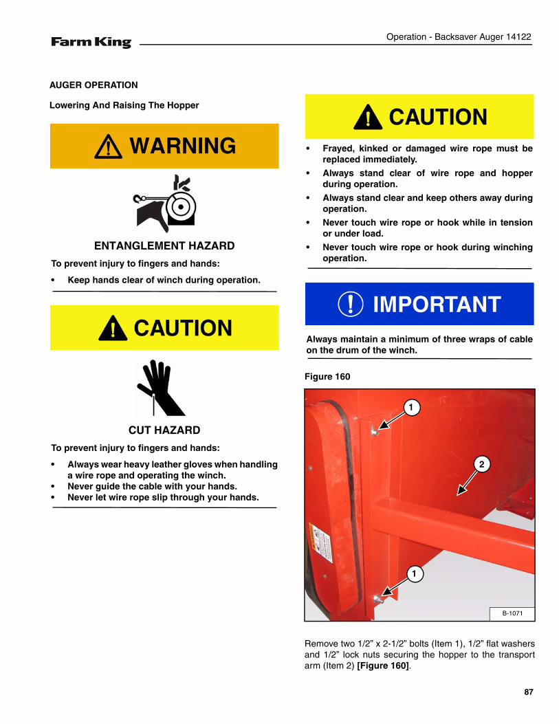
Operation - Backsaver Auger 14122
AUGER OPERATION
Lowering And Raising The Hopper
Figure 160
Remove two 1/2” x 2-1/2” bolts (Item 1), 1/2” flat washersand 1/2” lock nuts securing the hopper to the transportarm (Item 2) [Figure 160].
ENTANGLEMENT HAZARD
To prevent injury to fingers and hands:
• Keep hands clear of winch during operation.
CUT HAZARD
To prevent injury to fingers and hands:
• Always wear heavy leather gloves when handlinga wire rope and operating the winch.
• Never guide the cable with your hands.• Never let wire rope slip through your hands.
• Frayed, kinked or damaged wire rope must bereplaced immediately.
• Always stand clear of wire rope and hopperduring operation.
• Always stand clear and keep others away duringoperation.
• Never touch wire rope or hook while in tensionor under load.
• Never touch wire rope or hook during winchingoperation.
Always maintain a minimum of three wraps of cableon the drum of the winch.
B-1071
2
1
1
87
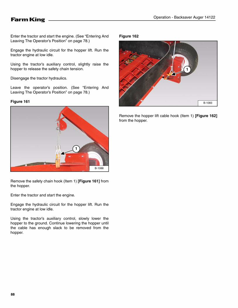
Operation - Backsaver Auger 14122
Enter the tractor and start the engine. (See “Entering AndLeaving The Operator’s Position” on page 78.)
Engage the hydraulic circuit for the hopper lift. Run thetractor engine at low idle.
Using the tractor’s auxiliary control, slightly raise thehopper to release the safety chain tension.
Disengage the tractor hydraulics.
Leave the operator’s position. (See “Entering AndLeaving The Operator’s Position” on page 78.)
Figure 161
Remove the safety chain hook (Item 1) [Figure 161] fromthe hopper.
Enter the tractor and start the engine.
Engage the hydraulic circuit for the hopper lift. Run thetractor engine at low idle.
Using the tractor’s auxiliary control, slowly lower thehopper to the ground. Continue lowering the hopper untilthe cable has enough slack to be removed from thehopper.
Figure 162
Remove the hopper lift cable hook (Item 1) [Figure 162]from the hopper.
B-1088
1
B-1083
1
88
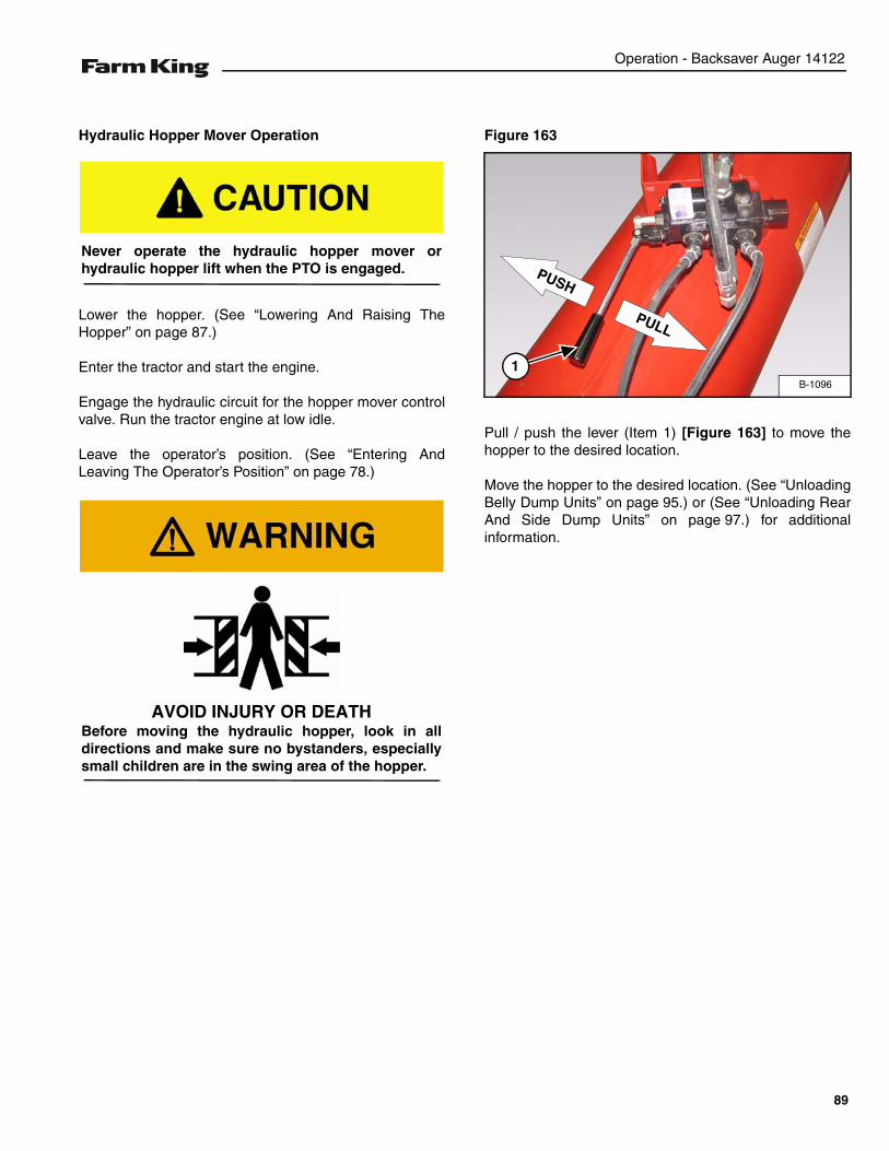
Operation - Backsaver Auger 14122
Hydraulic Hopper Mover Operation
Lower the hopper. (See “Lowering And Raising TheHopper” on page 87.)
Enter the tractor and start the engine.
Engage the hydraulic circuit for the hopper mover controlvalve. Run the tractor engine at low idle.
Leave the operator’s position. (See “Entering AndLeaving The Operator’s Position” on page 78.)
Figure 163
Pull / push the lever (Item 1) [Figure 163] to move thehopper to the desired location.
Move the hopper to the desired location. (See “UnloadingBelly Dump Units” on page 95.) or (See “Unloading RearAnd Side Dump Units” on page 97.) for additionalinformation.
Never operate the hydraulic hopper mover orhydraulic hopper lift when the PTO is engaged.
AVOID INJURY OR DEATHBefore moving the hydraulic hopper, look in alldirections and make sure no bystanders, especiallysmall children are in the swing area of the hopper.
B-1096
1
PUSH
PULL
89
Operation - Backsaver Auger 14122
Raising The Auger
ELECTROCUTION HAZARDTo prevent serious injury or death fromelectrocution:
• Be aware of overhead power lines.• Keep away from power lines when transporting
or raising auger.• Electrocution can occur without direct contact.
• Do not operate the unit before reading andunderstanding the Operator’s Manual.
• Keep all safety devices in place.
• Keep off the equipment at all times.
• Keep hands, feet and clothing away from movingparts while in operation.
• Make certain everyone is clear of the equipmentbefore applying power or moving the machine.
• Do not adjust, service, lubricate, clean, unclogor move the mechanism until all power is shutoff.
• While in operation, always support thedischarge end or provide adequate anchorage ofthe intake end to prevent sudden tipping.
• Disconnect power of electrical driven unitsbefore resetting motor over loads.
• To avoid tipping, make sure auger is emptybefore attempting to move.
• Keep wheels of undercarriage level and on firmground.
• Lower unit to the recommended transportposition before transporting.
• Do not raise the main auger higher than 35°before lowering the intake auger or interferencebetween the intake auger and the intake box willoccur.
• Never attempt to raise or lower the auger duringoperation.
• Verify wheels are free to move.
• Some types of fertilizer may cause acceleratedwear and corrosion as well as added stress onlift components due to additional load.
• Use of fertilizer can affect warranty.
Follow the instructions in your tractor’s operationmanual for the correct operating instructions.
90

Operation - Backsaver Auger 14122
Disconnect the PTO driveline from the tractor. (See“Connecting The PTO Driveline” on page 80.)
Enter the tractor, start the engine and release the parkingbrake.
Move the auger and tractor to the work area and park theauger and tractor on solid level surface.
Engage the tractor’s parking brake, stop the engine andexit the tractor.
Install the axle extensions (if required). (See “AxleExtension Installation” on page 85.)
Enter the tractor, start the engine and release the parkingbrake.
With the axle extensions installed and main auger in thefully down position, move the auger towards the bin orbarn. Position the auger as close as possible to the bin orbarn with the tractor as close to in-line with the auger aspossible.
Stop the tractor and engage the parking brake. Engagethe tractor’s hydraulics. Run the tractor engine at low idle.
Figure 164
Using the tractor controls, slowly raise the main auger.The track car (Item 1) will move down the upper trusssupport (Item 2) [Figure 164] raising the auger.
Disconnect The IID (PTO) from the tractor. Failure tofollow this step EVERY time BEFORE maneuveringOR changing the auger elevation may causedamage to the tractor and / or auger IID.
Keep wheels of undercarriage level and on firmground. Raise the auger to the desired height andback the auger into position. Do not support theauger on the bin. As the auger becomes full, theweight may cause damage to the underside of theauger or to the bin.
Do not place blocks under the wheels to increasethe elevation of auger.
B-1060
1
2
91
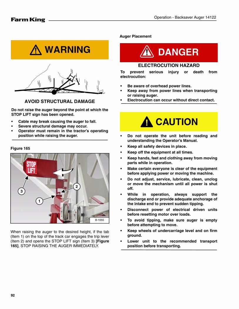
Operation - Backsaver Auger 14122
Figure 165
When raising the auger to the desired height, if the tab(Item 1) on the top of the track car engages the trip lever(Item 2) and opens the STOP LIFT sign (Item 3) [Figure165], STOP RAISING THE AUGER IMMEDIATELY.
Auger Placement
AVOID STRUCTURAL DAMAGE
Do not raise the auger beyond the point at which theSTOP LIFT sign has been opened.
• Cable may break causing the auger to fall.• Severe structural damage may occur.• Operator must remain in the tractor’s operating
position while raising the auger.
B-1055
1
23
ELECTROCUTION HAZARDTo prevent serious injury or death fromelectrocution:
• Be aware of overhead power lines.• Keep away from power lines when transporting
or raising auger.• Electrocution can occur without direct contact.
• Do not operate the unit before reading andunderstanding the Operator’s Manual.
• Keep all safety devices in place.
• Keep off the equipment at all times.
• Keep hands, feet and clothing away from movingparts while in operation.
• Make certain everyone is clear of the equipmentbefore applying power or moving the machine.
• Do not adjust, service, lubricate, clean, unclogor move the mechanism until all power is shutoff.
• While in operation, always support thedischarge end or provide adequate anchorage ofthe intake end to prevent sudden tipping.
• Disconnect power of electrical driven unitsbefore resetting motor over loads.
• To avoid tipping, make sure auger is emptybefore attempting to move.
• Keep wheels of undercarriage level and on firmground.
• Lower unit to the recommended transportposition before transporting.
92
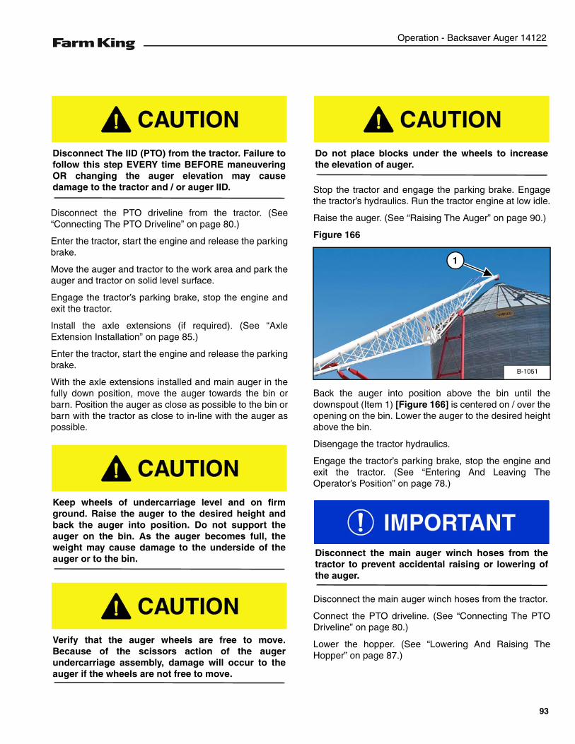
Operation - Backsaver Auger 14122
Disconnect the PTO driveline from the tractor. (See“Connecting The PTO Driveline” on page 80.)
Enter the tractor, start the engine and release the parkingbrake.
Move the auger and tractor to the work area and park theauger and tractor on solid level surface.
Engage the tractor’s parking brake, stop the engine andexit the tractor.
Install the axle extensions (if required). (See “AxleExtension Installation” on page 85.)
Enter the tractor, start the engine and release the parkingbrake.
With the axle extensions installed and main auger in thefully down position, move the auger towards the bin orbarn. Position the auger as close as possible to the bin orbarn with the tractor as close to in-line with the auger aspossible.
Stop the tractor and engage the parking brake. Engagethe tractor’s hydraulics. Run the tractor engine at low idle.
Raise the auger. (See “Raising The Auger” on page 90.)
Figure 166
Back the auger into position above the bin until thedownspout (Item 1) [Figure 166] is centered on / over theopening on the bin. Lower the auger to the desired heightabove the bin.
Disengage the tractor hydraulics.
Engage the tractor’s parking brake, stop the engine andexit the tractor. (See “Entering And Leaving TheOperator’s Position” on page 78.)
Disconnect the main auger winch hoses from the tractor.
Connect the PTO driveline. (See “Connecting The PTODriveline” on page 80.)
Lower the hopper. (See “Lowering And Raising TheHopper” on page 87.)
Disconnect The IID (PTO) from the tractor. Failure tofollow this step EVERY time BEFORE maneuveringOR changing the auger elevation may causedamage to the tractor and / or auger IID.
Keep wheels of undercarriage level and on firmground. Raise the auger to the desired height andback the auger into position. Do not support theauger on the bin. As the auger becomes full, theweight may cause damage to the underside of theauger or to the bin.
Verify that the auger wheels are free to move.Because of the scissors action of the augerundercarriage assembly, damage will occur to theauger if the wheels are not free to move.
Do not place blocks under the wheels to increasethe elevation of auger.
B-1051
1
Disconnect the main auger winch hoses from thetractor to prevent accidental raising or lowering ofthe auger.
93
Operation - Backsaver Auger 14122
Lowering The Auger
Disconnect the PTO driveline from the tractor. (See“Connecting The PTO Driveline” on page 80.)
Connect hydraulic hoses. (See “Connecting HydraulicHoses” on page 84.)
Raise the hopper. (See “Lowering And Raising TheHopper” on page 87.)
Enter the tractor, start the engine and release the parkingbrake.
Engage the tractor hydraulics.
NOTE: Verify that the discharge spout will clear thetop of the bin (raise auger if needed).
Move the auger and tractor away from the bin until thereis adequate space to fully lower the auger.
Engage the tractor’s parking brake, stop the engine andexit the tractor.
ELECTROCUTION HAZARDTo prevent serious injury or death fromelectrocution:
• Be aware of overhead power lines.• Keep away from power lines when transporting
or lowering the auger.• Electrocution can occur without direct contact.
• Do not operate the unit before reading andunderstanding the Operator’s Manual.
• Keep all safety devices in place.
• Keep off the equipment at all times.
• Keep hands, feet and clothing away from movingparts while in operation.
• Make certain everyone is clear of the equipmentbefore applying power or moving the machine.
• Do not adjust, service, lubricate, clean, unclogor move the mechanism until all power is shutoff.
• While in operation, always support thedischarge end or provide adequate anchorage ofthe intake end to prevent sudden tipping.
• Disconnect power of electrical driven unitsbefore resetting motor over loads.
• To avoid tipping, make sure auger is emptybefore attempting to move.
• Keep wheels of undercarriage level and on firmground.
• Lower unit to the recommended transportposition before transporting.
Disconnect The IID (PTO) from the tractor. Failure tofollow this step EVERY time BEFORE maneuveringOR changing the auger elevation may causedamage to the tractor and / or auger IID.
94
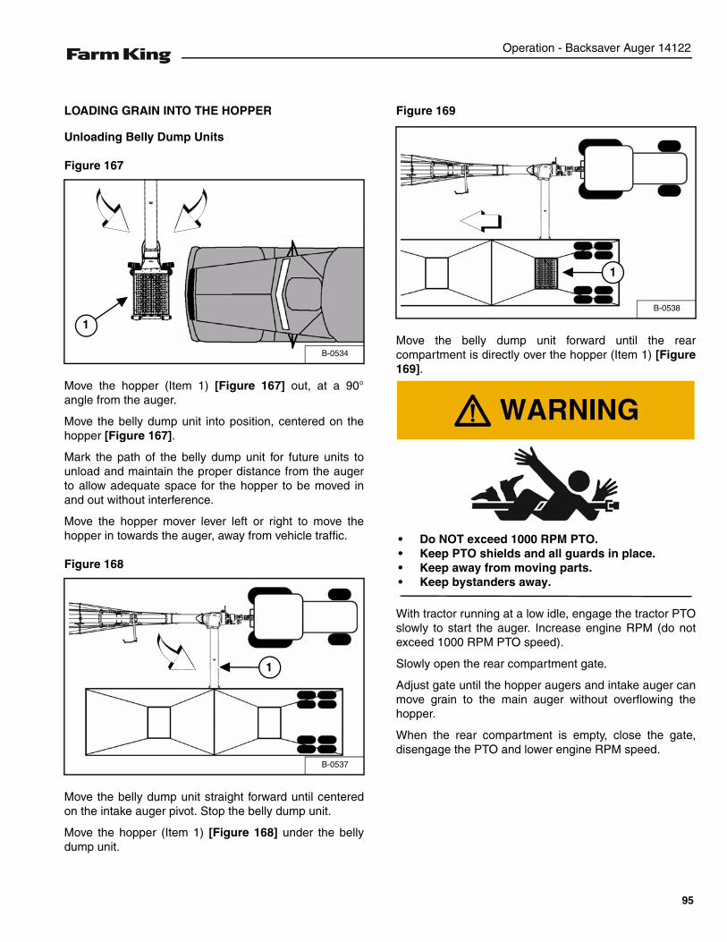
Operation - Backsaver Auger 14122
LOADING GRAIN INTO THE HOPPER
Unloading Belly Dump Units
Figure 167
Move the hopper (Item 1) [Figure 167] out, at a 90°angle from the auger.
Move the belly dump unit into position, centered on thehopper [Figure 167].
Mark the path of the belly dump unit for future units tounload and maintain the proper distance from the augerto allow adequate space for the hopper to be moved inand out without interference.
Move the hopper mover lever left or right to move thehopper in towards the auger, away from vehicle traffic.
Figure 168
Move the belly dump unit straight forward until centeredon the intake auger pivot. Stop the belly dump unit.
Move the hopper (Item 1) [Figure 168] under the bellydump unit.
Figure 169
Move the belly dump unit forward until the rearcompartment is directly over the hopper (Item 1) [Figure169].
With tractor running at a low idle, engage the tractor PTOslowly to start the auger. Increase engine RPM (do notexceed 1000 RPM PTO speed).
Slowly open the rear compartment gate.
Adjust gate until the hopper augers and intake auger canmove grain to the main auger without overflowing thehopper.
When the rear compartment is empty, close the gate,disengage the PTO and lower engine RPM speed.
B-0534
1
B-0537
1
B-0538
1
• Do NOT exceed 1000 RPM PTO.• Keep PTO shields and all guards in place.• Keep away from moving parts.• Keep bystanders away.
95
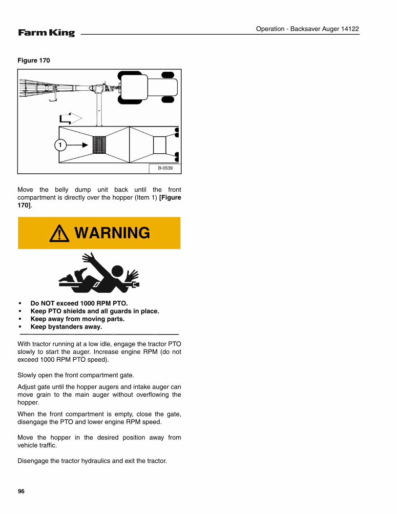
Operation - Backsaver Auger 14122
Figure 170
Move the belly dump unit back until the frontcompartment is directly over the hopper (Item 1) [Figure170].
With tractor running at a low idle, engage the tractor PTOslowly to start the auger. Increase engine RPM (do notexceed 1000 RPM PTO speed).
Slowly open the front compartment gate.
Adjust gate until the hopper augers and intake auger canmove grain to the main auger without overflowing thehopper.
When the front compartment is empty, close the gate,disengage the PTO and lower engine RPM speed.
Move the hopper in the desired position away fromvehicle traffic.
Disengage the tractor hydraulics and exit the tractor.
B-0539
1
• Do NOT exceed 1000 RPM PTO.• Keep PTO shields and all guards in place.• Keep away from moving parts.• Keep bystanders away.
96
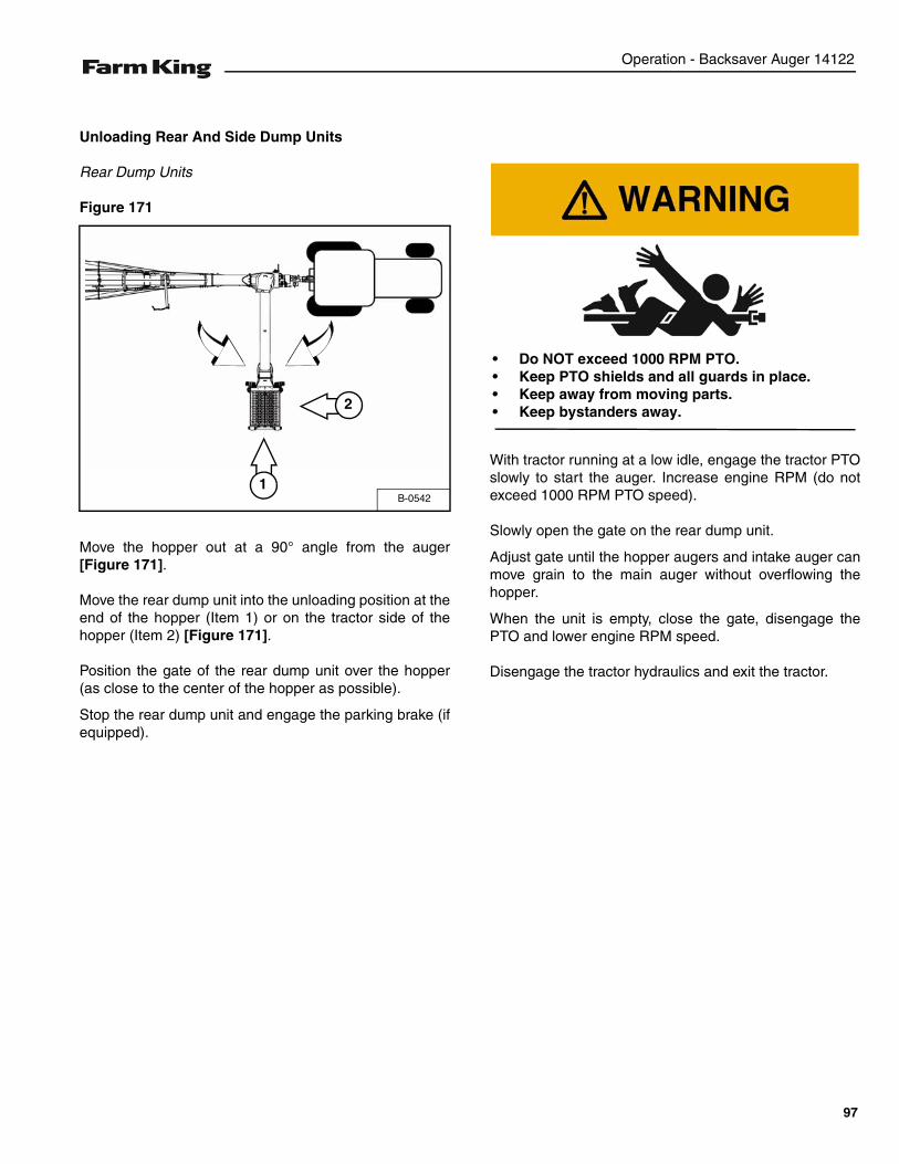
Operation - Backsaver Auger 14122
Unloading Rear And Side Dump Units
Rear Dump Units
Figure 171
Move the hopper out at a 90° angle from the auger[Figure 171].
Move the rear dump unit into the unloading position at theend of the hopper (Item 1) or on the tractor side of thehopper (Item 2) [Figure 171].
Position the gate of the rear dump unit over the hopper(as close to the center of the hopper as possible).
Stop the rear dump unit and engage the parking brake (ifequipped).
With tractor running at a low idle, engage the tractor PTOslowly to start the auger. Increase engine RPM (do notexceed 1000 RPM PTO speed).
Slowly open the gate on the rear dump unit.
Adjust gate until the hopper augers and intake auger canmove grain to the main auger without overflowing thehopper.
When the unit is empty, close the gate, disengage thePTO and lower engine RPM speed.
Disengage the tractor hydraulics and exit the tractor.
B-05421
2
• Do NOT exceed 1000 RPM PTO.• Keep PTO shields and all guards in place.• Keep away from moving parts.• Keep bystanders away.
97
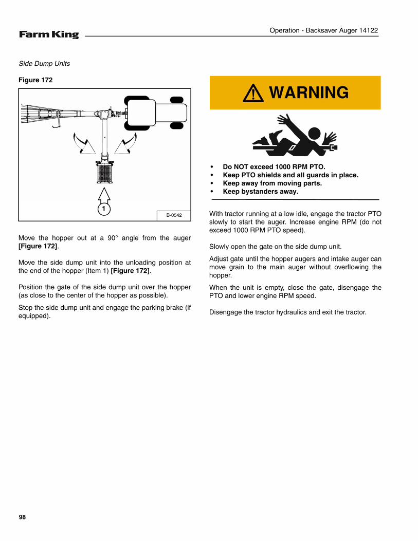
Operation - Backsaver Auger 14122
Side Dump Units
Figure 172
Move the hopper out at a 90° angle from the auger[Figure 172].
Move the side dump unit into the unloading position atthe end of the hopper (Item 1) [Figure 172].
Position the gate of the side dump unit over the hopper(as close to the center of the hopper as possible).
Stop the side dump unit and engage the parking brake (ifequipped).
With tractor running at a low idle, engage the tractor PTOslowly to start the auger. Increase engine RPM (do notexceed 1000 RPM PTO speed).
Slowly open the gate on the side dump unit.
Adjust gate until the hopper augers and intake auger canmove grain to the main auger without overflowing thehopper.
When the unit is empty, close the gate, disengage thePTO and lower engine RPM speed.
Disengage the tractor hydraulics and exit the tractor.
B-05421
• Do NOT exceed 1000 RPM PTO.• Keep PTO shields and all guards in place.• Keep away from moving parts.• Keep bystanders away.
98
Operation - Backsaver Auger 14122
TRANSPORTING
Requirements
Comply with federal, state, local and provincial lawsregarding the transport of farm equipment on pubicroadways.
Verify that the tractor / tow vehicle are approved fortransporting the equipment and that the equipment issecurely attached to the tractor / tow vehicle.
Verify safety chain is installed and properly connectedbefore transporting equipment.
Verify that the SMV (Slow Moving Vehicle) emblem, alllights and reflectors are clean and visible.
Always attach a red flag to the end of the auger whentransporting on roads.
Disconnect the PTO driveline from the tractor beforetransporting.
Transporting Guidelines
The ratio of the tractor / tow vehicle weight to the loadedequipment weight plays an important role in definingacceptable travel speed.
TRAVEL SPEED - Acceptable travel speed.
WEIGHT RATIO - Weight of fully equipped or loadedimplement(s) relative to weight of tractor / tow vehicle.
ELECTROCUTION HAZARDTo prevent serious injury or death fromelectrocution:
• Be aware of overhead power lines.• Keep away from power lines when transporting
or raising auger.• Electrocution can occur without direct contact.
Use of an unapproved hitch or tractor / tow vehiclecan result in loss of control, leading to seriousinjury or death.
Tractor / tow vehicle and hitch must have the ratedcapacity to tow equipment.
• Do not operate the unit before reading andunderstanding the Operator’s Manual.
• Make certain everyone is clear of the equipmentbefore applying power or moving the machine.
• To avoid tipping, make sure auger is emptybefore attempting to move.
• Keep wheels of undercarriage level and on firmground.
• Lower unit to the recommended transportposition before transporting.
• Disconnect PTO driveline from the tractor beforemoving or transporting. TRAVEL SPEED WEIGHT RATIO
Up to 20 mph (32 kph) 1 to 1 (or less)
Up to 10 mph (16 kph) 2 to 1 (or less)
DO NOT TOW More than 2 to 1
Never exceed 20 mph (32 kph).
Do not move or transport the auger unless thehopper and intake auger are in the raised / transportposition and securely fastened before transporting.
99
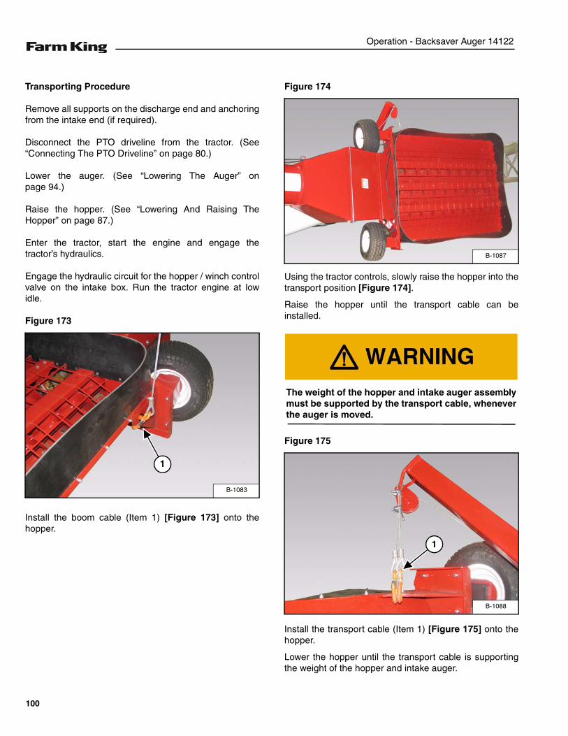
Operation - Backsaver Auger 14122
Transporting Procedure
Remove all supports on the discharge end and anchoringfrom the intake end (if required).
Disconnect the PTO driveline from the tractor. (See“Connecting The PTO Driveline” on page 80.)
Lower the auger. (See “Lowering The Auger” onpage 94.)
Raise the hopper. (See “Lowering And Raising TheHopper” on page 87.)
Enter the tractor, start the engine and engage thetractor’s hydraulics.
Engage the hydraulic circuit for the hopper / winch controlvalve on the intake box. Run the tractor engine at lowidle.
Figure 173
Install the boom cable (Item 1) [Figure 173] onto thehopper.
Figure 174
Using the tractor controls, slowly raise the hopper into thetransport position [Figure 174].
Raise the hopper until the transport cable can beinstalled.
Figure 175
Install the transport cable (Item 1) [Figure 175] onto thehopper.
Lower the hopper until the transport cable is supportingthe weight of the hopper and intake auger.
B-1083
1
B-1087
The weight of the hopper and intake auger assemblymust be supported by the transport cable, wheneverthe auger is moved.
B-1088
1
100
Operation - Backsaver Auger 14122
Engage the tractor’s parking brake, stop the engine andexit the tractor.
Figure 176
Align the two holes (Item 1) in the bottom of the hopperwith the two holes in the transport arm (Item 2) [Figure176].
Install two 1/2” x 2-1/2” bolts through the bottom of thehopper and transport arm. Install one 1/2” flat washerand 1/2” lock nut onto each bolt. Tighten the bolts andnuts to secure the hopper to the transport arm.
Figure 177
Place a 5 Ton jack (Item 1) [Figure 177] under the axle.
Raise the jack / axle until the tire is off the ground.
Place a jack stand (Item 2) [Figure 177] under the axle inthe raised position (tire off the ground).
B-1071
2
1
1
CRUSHING HAZARD
• Park the equipment on a solid level surfacebefore raising any part of the equipment.
• Always support the load after raised.• Do not work under a load supported by a jack or
blocked parts.
B-1017A
12
The base of the jack and jack stand should be fullysupported and on solid level surface. When workingon soft surfaces, put a sturdy metal plate under thebase of the jack for stability.
101
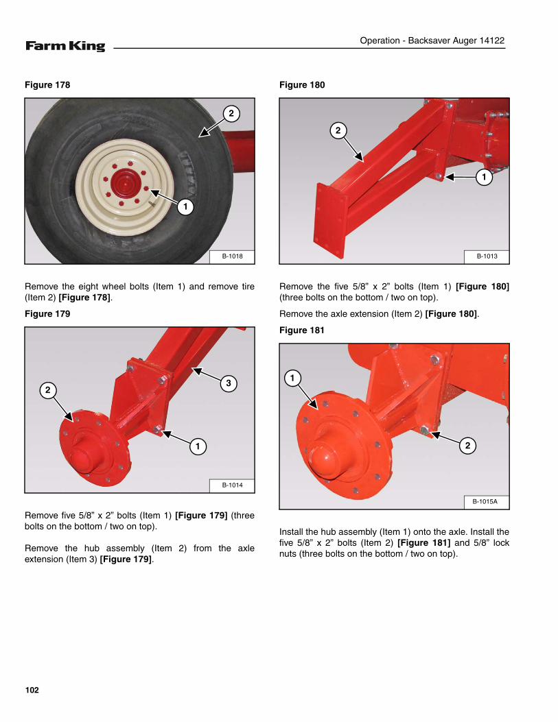
Operation - Backsaver Auger 14122
Figure 178
Remove the eight wheel bolts (Item 1) and remove tire(Item 2) [Figure 178].
Figure 179
Remove five 5/8” x 2” bolts (Item 1) [Figure 179] (threebolts on the bottom / two on top).
Remove the hub assembly (Item 2) from the axleextension (Item 3) [Figure 179].
Figure 180
Remove the five 5/8” x 2” bolts (Item 1) [Figure 180](three bolts on the bottom / two on top).
Remove the axle extension (Item 2) [Figure 180].
Figure 181
Install the hub assembly (Item 1) onto the axle. Install thefive 5/8” x 2” bolts (Item 2) [Figure 181] and 5/8” locknuts (three bolts on the bottom / two on top).
B-1018
1
2
B-1014
23
1
B-1013
2
1
B-1015A
1
2
102
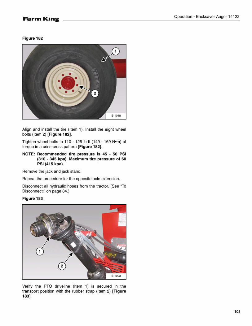
Operation - Backsaver Auger 14122
Figure 182
Align and install the tire (Item 1). Install the eight wheelbolts (Item 2) [Figure 182].
Tighten wheel bolts to 110 - 125 lb ft (149 - 169 N•m) oftorque in a criss-cross pattern [Figure 182].
NOTE: Recommended tire pressure is 45 - 50 PSI(310 - 345 kpa). Maximum tire pressure of 60PSI (415 kpa).
Remove the jack and jack stand.
Repeat the procedure for the opposite axle extension.
Disconnect all hydraulic hoses from the tractor. (See “ToDisconnect:” on page 84.)
Figure 183
Verify the PTO driveline (Item 1) is secured in thetransport position with the rubber strap (Item 2) [Figure183].
B-1018
2
1
B-1093
1
2
103

Operation - Backsaver Auger 14122
104
Maintenance - Backsaver Auger 14122
MAINTENANCE
TROUBLESHOOTING . . . . . . . . . . . . . . . . . . . . . . . . . . . . . . . . . . . . . . . . . . . . . . . . . . . . . . . . . . 107Chart . . . . . . . . . . . . . . . . . . . . . . . . . . . . . . . . . . . . . . . . . . . . . . . . . . . . . . . . . . . . . . . . . . . . . 107
SERVICE SCHEDULE . . . . . . . . . . . . . . . . . . . . . . . . . . . . . . . . . . . . . . . . . . . . . . . . . . . . . . . . . . 108Maintenance Intervals . . . . . . . . . . . . . . . . . . . . . . . . . . . . . . . . . . . . . . . . . . . . . . . . . . . . . . . . 108
LUBRICATION . . . . . . . . . . . . . . . . . . . . . . . . . . . . . . . . . . . . . . . . . . . . . . . . . . . . . . . . . . . . . . . . 109Recommendations . . . . . . . . . . . . . . . . . . . . . . . . . . . . . . . . . . . . . . . . . . . . . . . . . . . . . . . . . . 109Locations . . . . . . . . . . . . . . . . . . . . . . . . . . . . . . . . . . . . . . . . . . . . . . . . . . . . . . . . . . . . . . . . . . 109668 Upper Gearbox . . . . . . . . . . . . . . . . . . . . . . . . . . . . . . . . . . . . . . . . . . . . . . . . . . . . . . . . . 113968 Lower Gearbox . . . . . . . . . . . . . . . . . . . . . . . . . . . . . . . . . . . . . . . . . . . . . . . . . . . . . . . . . . 113Cleaning And Inspection . . . . . . . . . . . . . . . . . . . . . . . . . . . . . . . . . . . . . . . . . . . . . . . . . . . . . . 113
AXLE . . . . . . . . . . . . . . . . . . . . . . . . . . . . . . . . . . . . . . . . . . . . . . . . . . . . . . . . . . . . . . . . . . . . . . . 114Wheel Lug Nut Torque . . . . . . . . . . . . . . . . . . . . . . . . . . . . . . . . . . . . . . . . . . . . . . . . . . . . . . .114Tire / Wheel Replacement . . . . . . . . . . . . . . . . . . . . . . . . . . . . . . . . . . . . . . . . . . . . . . . . . . . . 114
SAFETY SIGN (DECAL) INSTALLATION . . . . . . . . . . . . . . . . . . . . . . . . . . . . . . . . . . . . . . . . . . . 115Procedure . . . . . . . . . . . . . . . . . . . . . . . . . . . . . . . . . . . . . . . . . . . . . . . . . . . . . . . . . . . . . . . . . 115
STORAGE AND RETURN TO SERVICE . . . . . . . . . . . . . . . . . . . . . . . . . . . . . . . . . . . . . . . . . . . . 116Storage . . . . . . . . . . . . . . . . . . . . . . . . . . . . . . . . . . . . . . . . . . . . . . . . . . . . . . . . . . . . . . . . . . . 116Return To Service . . . . . . . . . . . . . . . . . . . . . . . . . . . . . . . . . . . . . . . . . . . . . . . . . . . . . . . . . . .116
105

Maintenance - Backsaver Auger 14122
106
Maintenance - Backsaver Auger 14122
TROUBLESHOOTING
Chart
NOTE: If a problem is encountered that is difficult to solve, even after having read through this troubleshootingsection, please call your local distributor, dealer or factory. Before you call, please have this Operator AndParts Manual and the serial number of your machine at hand.
PROBLEM CAUSE CORRECTION
Excessive auger vibration. Improper break-in of the auger. Inspect flighting and / or tube. Replaceflighting and / or tube if damaged.
Running auger empty. Inspect flighting and / or tube. Replaceflighting and / or tube if damaged.
Bent auger flighting. Remove the flighting from the tube andinspect for straightness. Straighten theflight and re-install.
Improper PTO speed. Operate the auger at 1000 RPM PTOspeed. Adjust speed as required.
Excessive shear bolt failure. Starting or stopping the auger atmaximum PTO speed.
Start and stop the auger at reducedPTO speed (approximately 500 RPM).
Reduced PTO speed when full feedingthe intake hopper.
Increase the PTO speed or reduce feedrate.
Overloading the intake hopper. Avoid overloading and force-feeding ofthe hopper.
Starting the auger under load. Empty auger completely beforestopping.
Wet grain. Reduce the rate of flow into the intake hopper.
Plugging the auger. Reduced PTO speed when full feedingthe intake hopper.
Avoid overloading and force-feeding ofthe hopper.
Overloading the intake hopper. Avoid overloading and force-feeding ofthe hopper.
Foreign objects in the auger. Remove foreign objects from flightingand tube.
Wet grain. Reduce the rate of flow into the intake hopper.
Snow or ice in grain. Reduce the rate of flow into the intakehopper.
Instructions are necessary before operating or servicing equipment. Read and understand theOperator And Parts Manual and safety signs (decals) on equipment. Follow warnings andinstructions in the manuals when making repairs, adjustments or servicing. Check for correctfunction after adjustments, repairs or service. Untrained operators and failure to follow instructionscan cause injury or death.
107
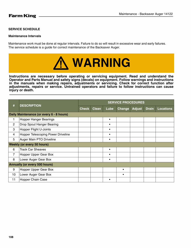
Maintenance - Backsaver Auger 14122
SERVICE SCHEDULE
Maintenance Intervals
Maintenance work must be done at regular intervals. Failure to do so will result in excessive wear and early failures.The service schedule is a guide for correct maintenance of the Backsaver Auger.
# DESCRIPTIONSERVICE PROCEDURES
Check Clean Lube Change Adjust Drain Locations
Daily Maintenance (or every 6 - 8 hours)
1 Hopper Hanger Bearings •
2 Drop Spout Hanger Bearing •
3 Hopper Flight U-Joints •
4 Hopper Telescoping Power Driveline •
5 Auger Main PTO Driveline •
Weekly (or every 50 hours)
6 Track Car Sheaves •
7 Hopper Upper Gear Box •
8 Lower Auger Gear Box •
Annually (or every 500 hours)
9 Hopper Upper Gear Box •
10 Lower Auger Gear Box •
11 Hopper Chain Case •
Instructions are necessary before operating or servicing equipment. Read and understand theOperator and Parts Manual and safety signs (decals) on equipment. Follow warnings and instructionsin the manuals when making repairs, adjustments or servicing. Check for correct function afteradjustments, repairs or service. Untrained operators and failure to follow instructions can causeinjury or death.
108
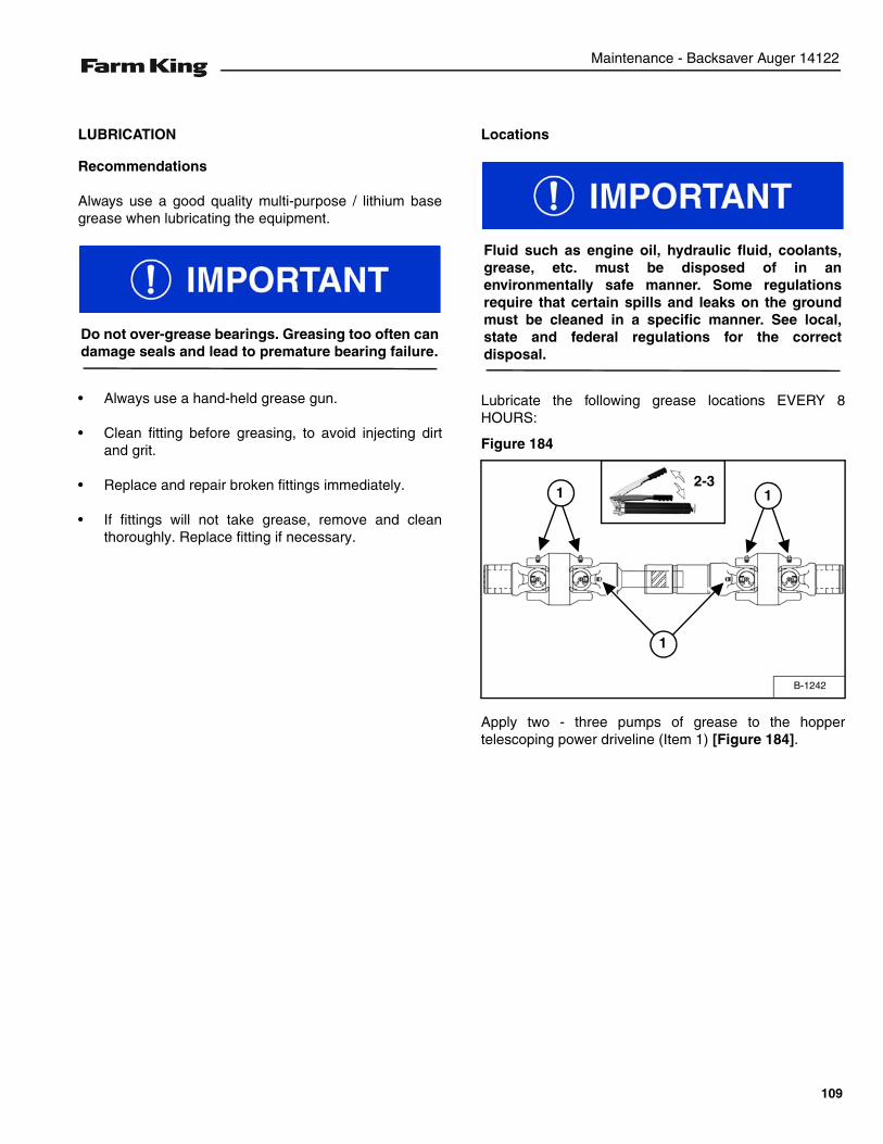
Maintenance - Backsaver Auger 14122
LUBRICATION
Recommendations
Always use a good quality multi-purpose / lithium basegrease when lubricating the equipment.
• Always use a hand-held grease gun.
• Clean fitting before greasing, to avoid injecting dirtand grit.
• Replace and repair broken fittings immediately.
• If fittings will not take grease, remove and cleanthoroughly. Replace fitting if necessary.
Locations
Lubricate the following grease locations EVERY 8HOURS:
Figure 184
Apply two - three pumps of grease to the hoppertelescoping power driveline (Item 1) [Figure 184].
Do not over-grease bearings. Greasing too often candamage seals and lead to premature bearing failure.
Fluid such as engine oil, hydraulic fluid, coolants,grease, etc. must be disposed of in anenvironmentally safe manner. Some regulationsrequire that certain spills and leaks on the groundmust be cleaned in a specific manner. See local,state and federal regulations for the correctdisposal.
B-1242
2-311
1
109
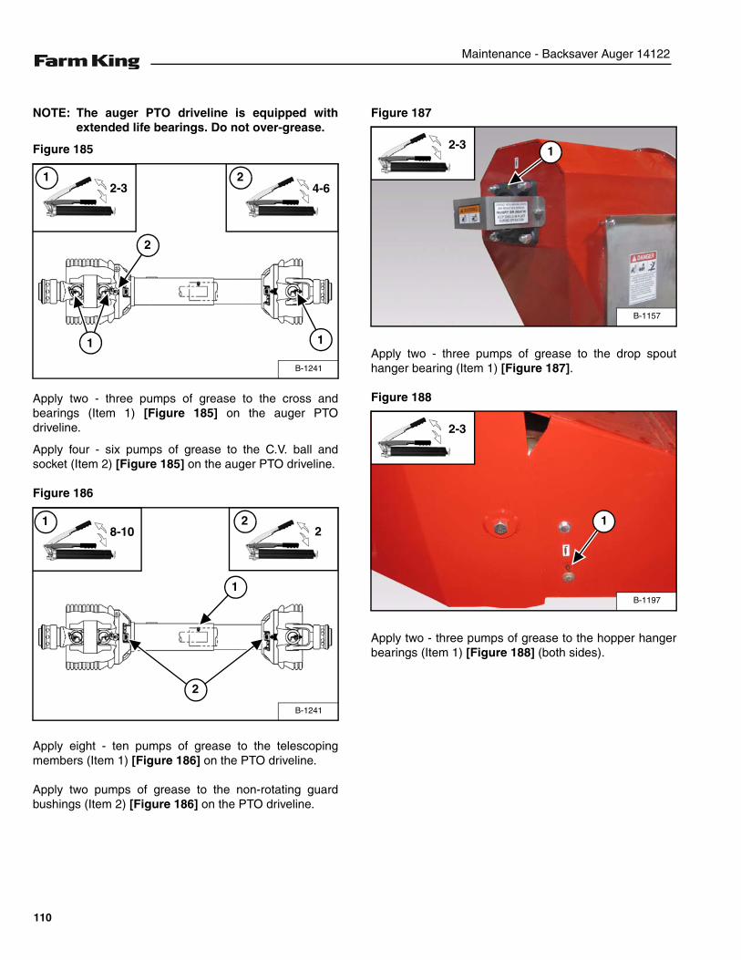
Maintenance - Backsaver Auger 14122
NOTE: The auger PTO driveline is equipped withextended life bearings. Do not over-grease.
Figure 185
Apply two - three pumps of grease to the cross andbearings (Item 1) [Figure 185] on the auger PTOdriveline.
Apply four - six pumps of grease to the C.V. ball andsocket (Item 2) [Figure 185] on the auger PTO driveline.
Figure 186
Apply eight - ten pumps of grease to the telescopingmembers (Item 1) [Figure 186] on the PTO driveline.
Apply two pumps of grease to the non-rotating guardbushings (Item 2) [Figure 186] on the PTO driveline.
Figure 187
Apply two - three pumps of grease to the drop spouthanger bearing (Item 1) [Figure 187].
Figure 188
Apply two - three pumps of grease to the hopper hangerbearings (Item 1) [Figure 188] (both sides).
B-1241
1
2-31
1
4-62
2
B-1241
2
22
1
8-101
B-1157
2-3 1
B-1197
2-3
1
110
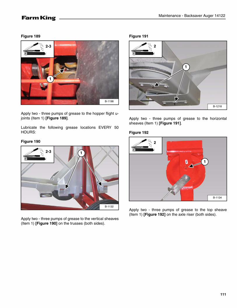
Maintenance - Backsaver Auger 14122
Figure 189
Apply two - three pumps of grease to the hopper flight u-joints (Item 1) [Figure 189].
Lubricate the following grease locations EVERY 50HOURS:
Figure 190
Apply two - three pumps of grease to the vertical sheaves(Item 1) [Figure 190] on the trusses (both sides).
Figure 191
Apply two - three pumps of grease to the horizontalsheaves (Item 1) [Figure 191].
Figure 192
Apply two - three pumps of grease to the top sheave(Item 1) [Figure 192] on the axle riser (both sides).
B-1198
1
2-3
B-1132
2-3 1
B-1218
2
1
B-1134
1
2
111
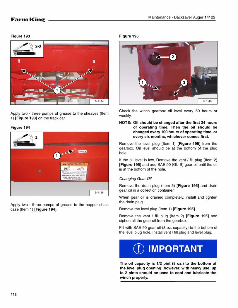
Maintenance - Backsaver Auger 14122
Figure 193
Apply two - three pumps of grease to the sheaves (Item1) [Figure 193] on the track car.
Figure 194
Apply two - three pumps of grease to the hopper chaincase (Item 1) [Figure 194].
Figure 195
Check the winch gearbox oil level every 50 hours orweekly.
NOTE: Oil should be changed after the first 24 hoursof operating time. Then the oil should bechanged every 100 hours of operating time, orevery six months, whichever comes first.
Remove the level plug (Item 1) [Figure 195] from thegearbox. Oil level should be at the bottom of the plughole.
If the oil level is low, Remove the vent / fill plug (Item 2)[Figure 195] and add SAE 90 (GL-S) gear oil until the oilis at the bottom of the hole.
Changing Gear Oil
Remove the drain plug (Item 3) [Figure 195] and draingear oil in a collection container.
When gear oil is drained completely, install and tightenthe drain plug.
Remove the level plug (Item 1) [Figure 195].
Remove the vent / fill plug (Item 2) [Figure 195] andsiphon all the gear oil from the gearbox.
Fill with SAE 90 gear oil (8 oz. capacity) to the bottom ofthe level plug hole. Install vent / fill plug and level plug.
B-1184
2-3
1
B-1196
1
2
B-1086
1 3
2
The oil capacity is 1/2 pint (8 oz.) to the bottom ofthe level plug opening; however, with heavy use, upto 2 pints should be used to cool and lubricate thewinch properly.
112
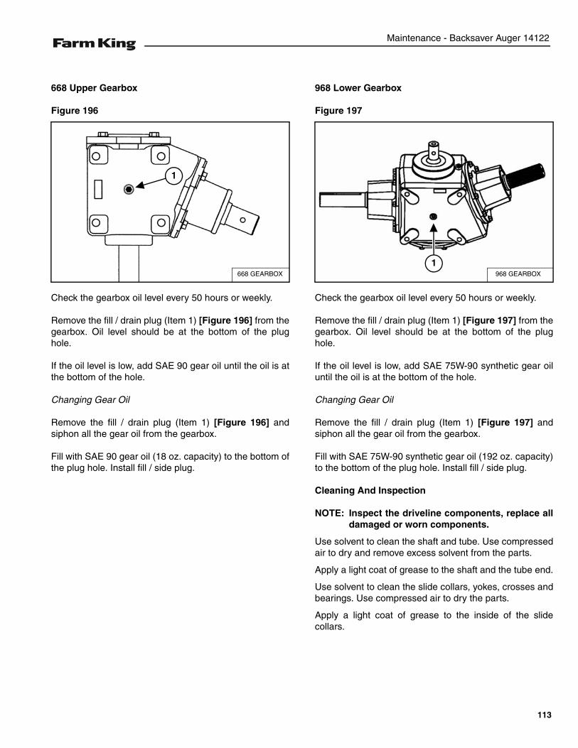
Maintenance - Backsaver Auger 14122
668 Upper Gearbox
Figure 196
Check the gearbox oil level every 50 hours or weekly.
Remove the fill / drain plug (Item 1) [Figure 196] from thegearbox. Oil level should be at the bottom of the plughole.
If the oil level is low, add SAE 90 gear oil until the oil is atthe bottom of the hole.
Changing Gear Oil
Remove the fill / drain plug (Item 1) [Figure 196] andsiphon all the gear oil from the gearbox.
Fill with SAE 90 gear oil (18 oz. capacity) to the bottom ofthe plug hole. Install fill / side plug.
968 Lower Gearbox
Figure 197
Check the gearbox oil level every 50 hours or weekly.
Remove the fill / drain plug (Item 1) [Figure 197] from thegearbox. Oil level should be at the bottom of the plughole.
If the oil level is low, add SAE 75W-90 synthetic gear oiluntil the oil is at the bottom of the hole.
Changing Gear Oil
Remove the fill / drain plug (Item 1) [Figure 197] andsiphon all the gear oil from the gearbox.
Fill with SAE 75W-90 synthetic gear oil (192 oz. capacity)to the bottom of the plug hole. Install fill / side plug.
Cleaning And Inspection
NOTE: Inspect the driveline components, replace alldamaged or worn components.
Use solvent to clean the shaft and tube. Use compressedair to dry and remove excess solvent from the parts.
Apply a light coat of grease to the shaft and the tube end.
Use solvent to clean the slide collars, yokes, crosses andbearings. Use compressed air to dry the parts.
Apply a light coat of grease to the inside of the slidecollars.
668 GEARBOX
1
968 GEARBOX
1
113

Maintenance - Backsaver Auger 14122
AXLE
Wheel Lug Nut Torque
Check the torque on wheel lug nuts daily. Tighten lugnuts to 110 - 125 lb. / ft. (149 - 169 N•m) torque.
Tire / Wheel Replacement
Empty the Backsaver Auger (if required).
Park the tractor / equipment on a flat level surface.
Place all controls in neutral, engage the park brake, stopthe engine and wait for all moving parts to stop. Leavethe operator’s position.
Place chock blocks behind and in front of the augertire(s).
Place a jack under the axle frame on the side the wheel isto be replaced. Raise the jack until the wheel is slightlyoff the ground.
NOTE: Place blocks under the frame to help securethe auger when wheel is raised off the ground.
Figure 198
Tighten wheel nuts in a criss-cross pattern [Figure 198].Tighten wheel nuts to 110 - 125 lb ft (149 - 169 N•m) oftorque.
Lower the axle and tires to the ground. Remove the liftingdevice.
Check tire pressure.
NOTE: Recommended tire pressure is 45 - 50 PSI(310 - 345 kpa). Maximum tire pressure of 60PSI (415 kpa).
AVOID INJURY OR DEATH
Before you leave the operator’s position:
• Always park on a flat level surface.• Place all controls in NEUTRAL.• Engage the park brake.• Stop the engine and remove the key.• Wait for all moving parts to stop.
AVOID INJURY OR DEATH• The parking brake must be engaged before
leaving the operator’s position. Rollaway canoccur because the transmission may notprevent machine movement.
• Always chock tires before performing anymaintenance or service.
B-1018
1
2
3
4
5
6
7
8
114
Maintenance - Backsaver Auger 14122
SAFETY SIGN (DECAL) INSTALLATION
Procedure
• Remove all portions of the damaged safety sign(decal).
• Thoroughly clean the area with glass cleaner.Removing all adhesive residue.
• Allow the area to dry completely before installing thenew safety sign (decal).
• Position the safety sign (decal) in the correct location.Remove a small portion of the backing paper on thesafety sign (decal).
• Press on the safety sign (decal) where the backingpaper has been removed.
• Slowly remove the remaining backing paper, pressingon the safety sign (decal) as the backing paper isremoved.
• Using the backing paper, pressing firmly, move thebacking paper over the entire safety sign (decal) area.
NOTE: Small air pockets can be pierced with a pinand smoothed out using the piece of thebacking paper.
When replacing safety signs (decals), thetemperature must be above 10° C (50° F).
115
Maintenance - Backsaver Auger 14122
STORAGE AND RETURN TO SERVICE
Storage
Sometimes it may be necessary to store your Farm KingBacksaver Auger for an extended period of time. Below isa list of items to perform before storage.
• Thoroughly clean the equipment.
• Lubricate the equipment.
• Inspect the hitch and all welds on the equipment forwear and damage.
• Check for loose hardware, missing guards, ordamaged parts.
• Check for damaged or missing safety signs (decals).Replace if necessary.
• Replace worn or damaged parts.
• Touch up all paint nicks and scratches to preventrusting.
• Check the tightness of all cable clamps to avoidslipping.
• Inspect the cables for wear or corrosion. Replace ifworn.
• Lubricate the cables.
• If stored outside, lower the auger to its lowest positionand block the wheels so the auger will not move.
• Place the equipment flat on the ground.
Return To Service
After the Farm King Backsaver Auger has been instorage, it is necessary to follow a list of items to returnthe equipment to service.
• Be sure all shields and guards are in place.
• Lubricate the equipment.
• Connect to a tractor and operate equipment, verify allfunctions operate correctly.
• Check for leaks. Repair as needed.
DO NOT permit children to play on or around thestored machine.
116
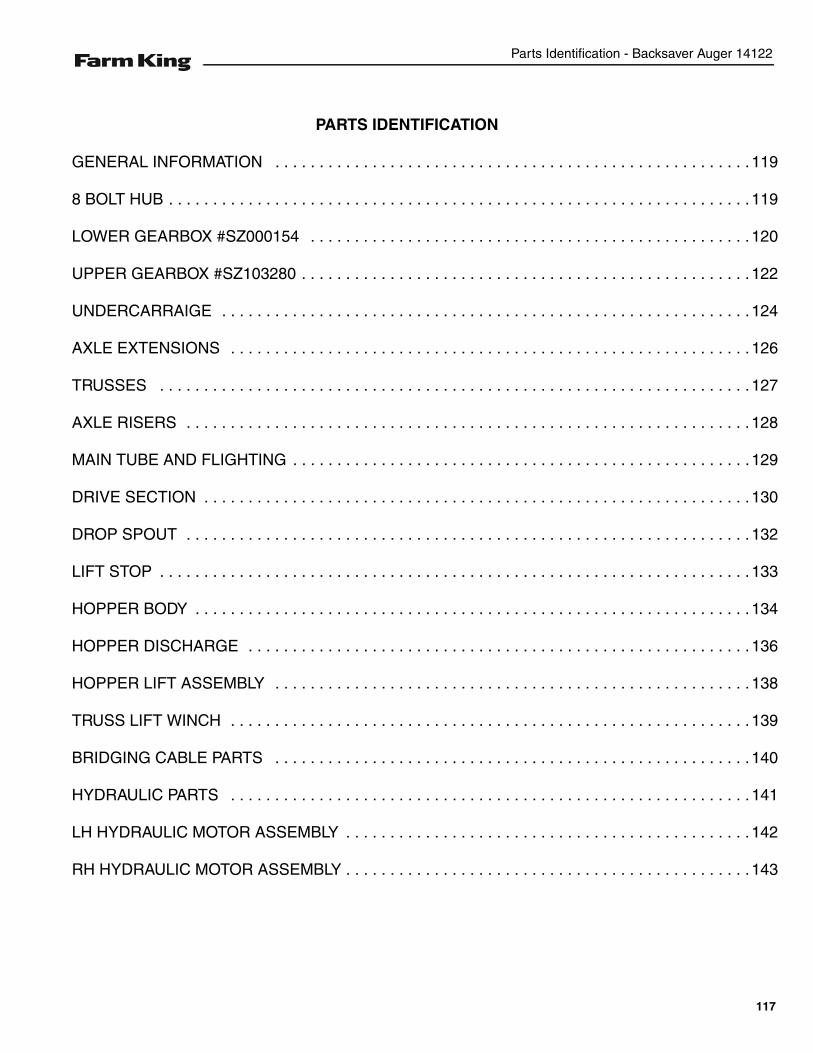
Parts Identification - Backsaver Auger 14122
PARTS IDENTIFICATION
GENERAL INFORMATION . . . . . . . . . . . . . . . . . . . . . . . . . . . . . . . . . . . . . . . . . . . . . . . . . . . . . . 119
8 BOLT HUB . . . . . . . . . . . . . . . . . . . . . . . . . . . . . . . . . . . . . . . . . . . . . . . . . . . . . . . . . . . . . . . . . . 119
LOWER GEARBOX #SZ000154 . . . . . . . . . . . . . . . . . . . . . . . . . . . . . . . . . . . . . . . . . . . . . . . . . . 120
UPPER GEARBOX #SZ103280 . . . . . . . . . . . . . . . . . . . . . . . . . . . . . . . . . . . . . . . . . . . . . . . . . . . 122
UNDERCARRAIGE . . . . . . . . . . . . . . . . . . . . . . . . . . . . . . . . . . . . . . . . . . . . . . . . . . . . . . . . . . . . 124
AXLE EXTENSIONS . . . . . . . . . . . . . . . . . . . . . . . . . . . . . . . . . . . . . . . . . . . . . . . . . . . . . . . . . . . 126
TRUSSES . . . . . . . . . . . . . . . . . . . . . . . . . . . . . . . . . . . . . . . . . . . . . . . . . . . . . . . . . . . . . . . . . . . 127
AXLE RISERS . . . . . . . . . . . . . . . . . . . . . . . . . . . . . . . . . . . . . . . . . . . . . . . . . . . . . . . . . . . . . . . . 128
MAIN TUBE AND FLIGHTING . . . . . . . . . . . . . . . . . . . . . . . . . . . . . . . . . . . . . . . . . . . . . . . . . . . .129
DRIVE SECTION . . . . . . . . . . . . . . . . . . . . . . . . . . . . . . . . . . . . . . . . . . . . . . . . . . . . . . . . . . . . . . 130
DROP SPOUT . . . . . . . . . . . . . . . . . . . . . . . . . . . . . . . . . . . . . . . . . . . . . . . . . . . . . . . . . . . . . . . . 132
LIFT STOP . . . . . . . . . . . . . . . . . . . . . . . . . . . . . . . . . . . . . . . . . . . . . . . . . . . . . . . . . . . . . . . . . . . 133
HOPPER BODY . . . . . . . . . . . . . . . . . . . . . . . . . . . . . . . . . . . . . . . . . . . . . . . . . . . . . . . . . . . . . . . 134
HOPPER DISCHARGE . . . . . . . . . . . . . . . . . . . . . . . . . . . . . . . . . . . . . . . . . . . . . . . . . . . . . . . . . 136
HOPPER LIFT ASSEMBLY . . . . . . . . . . . . . . . . . . . . . . . . . . . . . . . . . . . . . . . . . . . . . . . . . . . . . . 138
TRUSS LIFT WINCH . . . . . . . . . . . . . . . . . . . . . . . . . . . . . . . . . . . . . . . . . . . . . . . . . . . . . . . . . . . 139
BRIDGING CABLE PARTS . . . . . . . . . . . . . . . . . . . . . . . . . . . . . . . . . . . . . . . . . . . . . . . . . . . . . . 140
HYDRAULIC PARTS . . . . . . . . . . . . . . . . . . . . . . . . . . . . . . . . . . . . . . . . . . . . . . . . . . . . . . . . . . . 141
LH HYDRAULIC MOTOR ASSEMBLY . . . . . . . . . . . . . . . . . . . . . . . . . . . . . . . . . . . . . . . . . . . . . . 142
RH HYDRAULIC MOTOR ASSEMBLY . . . . . . . . . . . . . . . . . . . . . . . . . . . . . . . . . . . . . . . . . . . . . . 143
117

Parts Identification - Backsaver Auger 14122
118
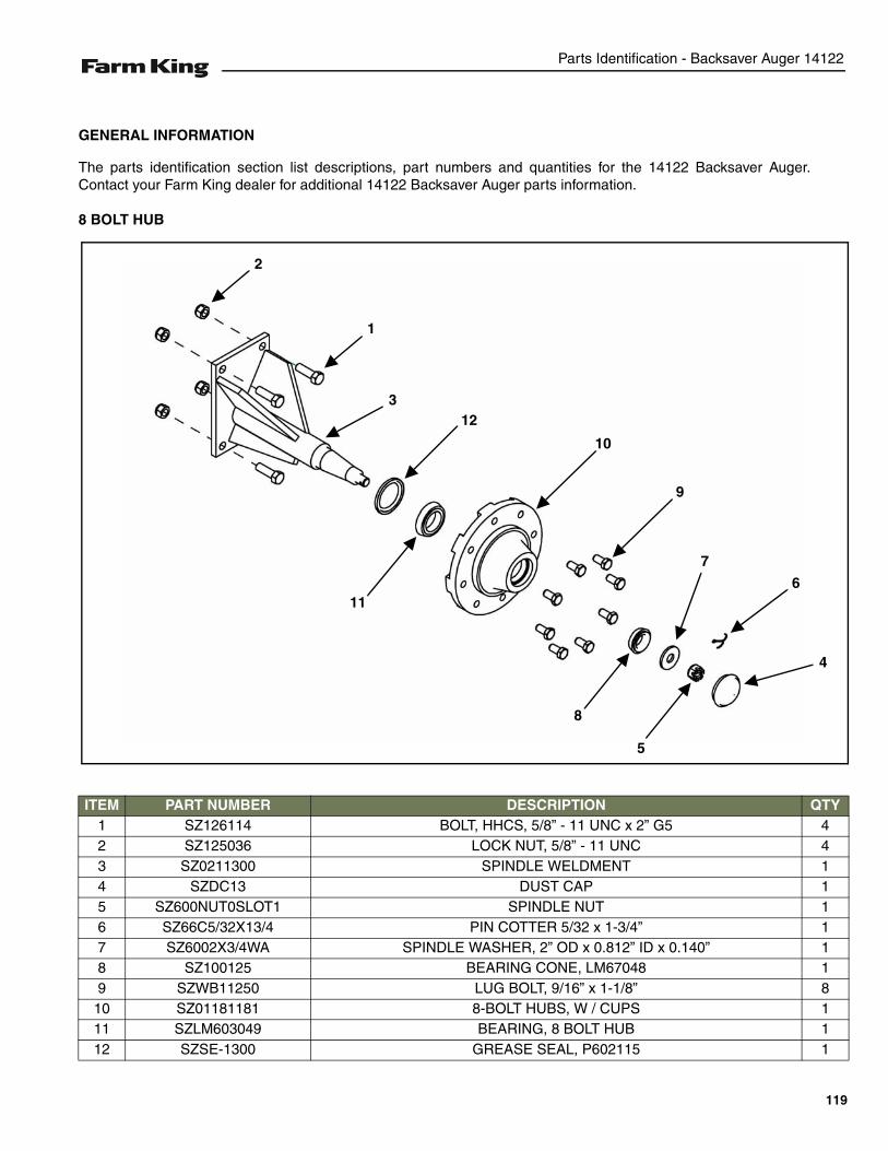
Parts Identification - Backsaver Auger 14122
GENERAL INFORMATION
The parts identification section list descriptions, part numbers and quantities for the 14122 Backsaver Auger.Contact your Farm King dealer for additional 14122 Backsaver Auger parts information.
8 BOLT HUB
ITEM PART NUMBER DESCRIPTION QTY1 SZ126114 BOLT, HHCS, 5/8” - 11 UNC x 2” G5 42 SZ125036 LOCK NUT, 5/8” - 11 UNC 43 SZ0211300 SPINDLE WELDMENT 14 SZDC13 DUST CAP 15 SZ600NUT0SLOT1 SPINDLE NUT 16 SZ66C5/32X13/4 PIN COTTER 5/32 x 1-3/4” 17 SZ6002X3/4WA SPINDLE WASHER, 2” OD x 0.812” ID x 0.140” 18 SZ100125 BEARING CONE, LM67048 19 SZWB11250 LUG BOLT, 9/16” x 1-1/8” 8
10 SZ01181181 8-BOLT HUBS, W / CUPS 111 SZLM603049 BEARING, 8 BOLT HUB 112 SZSE-1300 GREASE SEAL, P602115 1
3
2
1
12
11
10
9
8
5
7
6
4
119
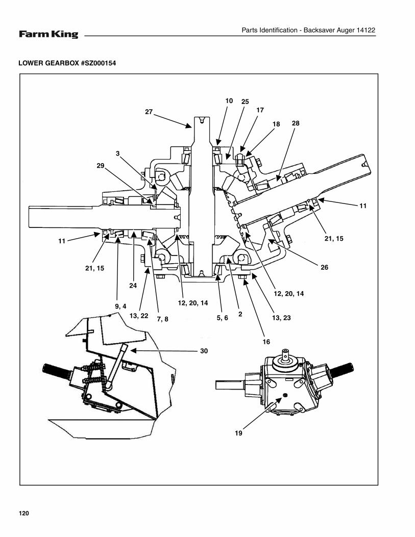
Parts Identification - Backsaver Auger 14122
LOWER GEARBOX #SZ000154
27
10 2517
18 28
21, 15
11
26
12, 20, 14
13, 23
16
25, 6
12, 20, 14
7, 813, 22
24
9, 4
21, 15
11
29
3
19
30
120
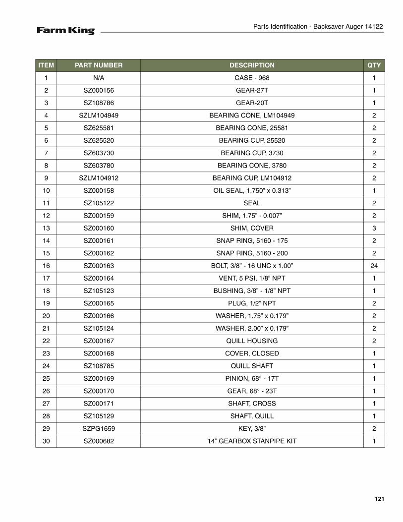
Parts Identification - Backsaver Auger 14122
ITEM PART NUMBER DESCRIPTION QTY
1 N/A CASE - 968 1
2 SZ000156 GEAR-27T 1
3 SZ108786 GEAR-20T 1
4 SZLM104949 BEARING CONE, LM104949 2
5 SZ625581 BEARING CONE, 25581 2
6 SZ625520 BEARING CUP, 25520 2
7 SZ603730 BEARING CUP, 3730 2
8 SZ603780 BEARING CONE, 3780 2
9 SZLM104912 BEARING CUP, LM104912 2
10 SZ000158 OIL SEAL, 1.750” x 0.313” 1
11 SZ105122 SEAL 2
12 SZ000159 SHIM, 1.75” - 0.007” 2
13 SZ000160 SHIM, COVER 3
14 SZ000161 SNAP RING, 5160 - 175 2
15 SZ000162 SNAP RING, 5160 - 200 2
16 SZ000163 BOLT, 3/8” - 16 UNC x 1.00” 24
17 SZ000164 VENT, 5 PSI, 1/8” NPT 1
18 SZ105123 BUSHING, 3/8” - 1/8” NPT 1
19 SZ000165 PLUG, 1/2” NPT 2
20 SZ000166 WASHER, 1.75” x 0.179” 2
21 SZ105124 WASHER, 2.00” x 0.179” 2
22 SZ000167 QUILL HOUSING 2
23 SZ000168 COVER, CLOSED 1
24 SZ108785 QUILL SHAFT 1
25 SZ000169 PINION, 68° - 17T 1
26 SZ000170 GEAR, 68° - 23T 1
27 SZ000171 SHAFT, CROSS 1
28 SZ105129 SHAFT, QUILL 1
29 SZPG1659 KEY, 3/8” 2
30 SZ000682 14” GEARBOX STANPIPE KIT 1
121
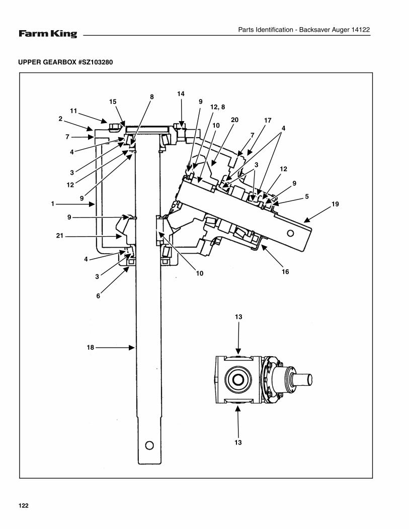
Parts Identification - Backsaver Auger 14122
UPPER GEARBOX #SZ103280
1
2
4
15
12
9
8
7
3
9
4
3
6
21
18
149
12, 8
1020
7
17
3
4
12
9
519
16
13
13
10
11
122
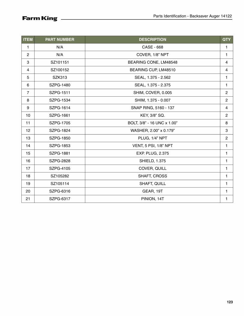
Parts Identification - Backsaver Auger 14122
ITEM PART NUMBER DESCRIPTION QTY
1 N/A CASE - 668 1
2 N/A COVER, 1/8” NPT 1
3 SZ101151 BEARING CONE, LM48548 4
4 SZ100152 BEARING CUP, LM48510 4
5 SZK313 SEAL, 1.375 - 2.562 1
6 SZPG-1480 SEAL, 1.375 - 2.375 1
7 SZPG-1511 SHIM, COVER, 0.005 2
8 SZPG-1534 SHIM, 1.375 - 0.007 2
9 SZPG-1614 SNAP RING, 5160 - 137 4
10 SZPG-1661 KEY, 3/8” SQ. 2
11 SZPG-1705 BOLT, 3/8” - 16 UNC x 1.00” 8
12 SZPG-1824 WASHER, 2.00” x 0.179” 3
13 SZPG-1850 PLUG, 1/4” NPT 2
14 SZPG-1853 VENT, 5 PSI, 1/8” NPT 1
15 SZPG-1881 EXP. PLUG, 2.375 1
16 SZPG-2828 SHIELD, 1.375 1
17 SZPG-4105 COVER, QUILL 1
18 SZ105282 SHAFT, CROSS 1
19 SZ105114 SHAFT, QUILL 1
20 SZPG-6316 GEAR, 19T 1
21 SZPG-6317 PINION, 14T 1
123
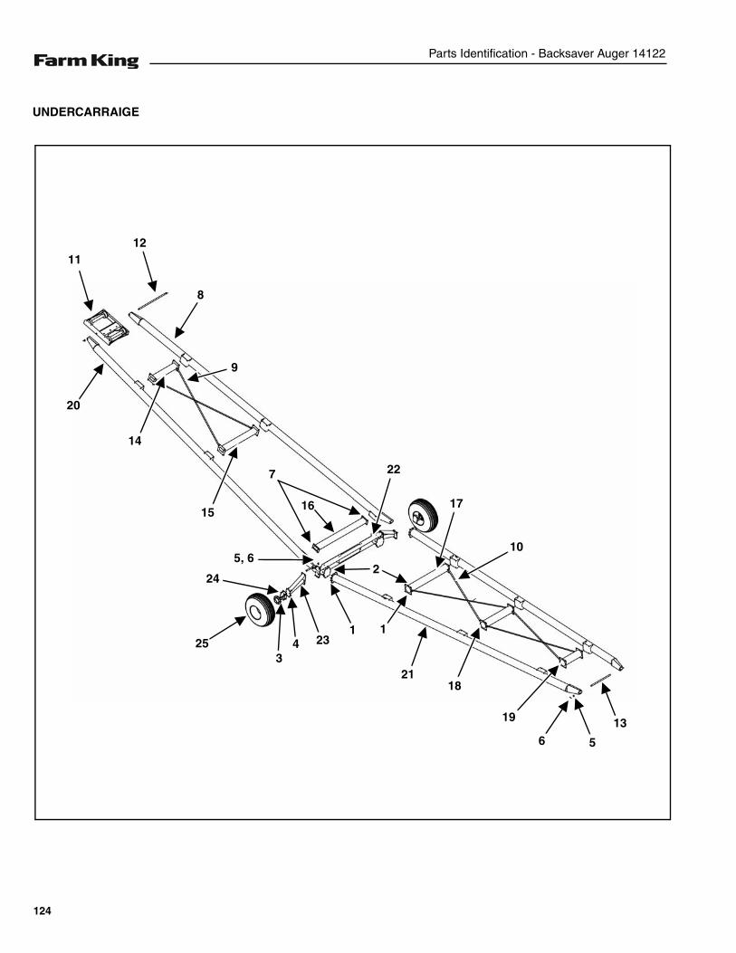
Parts Identification - Backsaver Auger 14122
UNDERCARRAIGE
8
1211
20
14
9
1517
10
13
2118
19
6 5
1
3425
24
7
16
5, 6
1
2
23
22
124
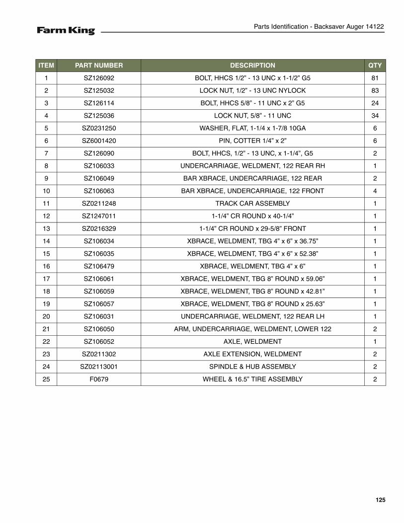
Parts Identification - Backsaver Auger 14122
ITEM PART NUMBER DESCRIPTION QTY
1 SZ126092 BOLT, HHCS 1/2” - 13 UNC x 1-1/2” G5 81
2 SZ125032 LOCK NUT, 1/2” - 13 UNC NYLOCK 83
3 SZ126114 BOLT, HHCS 5/8” - 11 UNC x 2” G5 24
4 SZ125036 LOCK NUT, 5/8” - 11 UNC 34
5 SZ0231250 WASHER, FLAT, 1-1/4 x 1-7/8 10GA 6
6 SZ6001420 PIN, COTTER 1/4” x 2” 6
7 SZ126090 BOLT, HHCS, 1/2” - 13 UNC, x 1-1/4”, G5 2
8 SZ106033 UNDERCARRIAGE, WELDMENT, 122 REAR RH 1
9 SZ106049 BAR XBRACE, UNDERCARRIAGE, 122 REAR 2
10 SZ106063 BAR XBRACE, UNDERCARRIAGE, 122 FRONT 4
11 SZ0211248 TRACK CAR ASSEMBLY 1
12 SZ1247011 1-1/4” CR ROUND x 40-1/4” 1
13 SZ0216329 1-1/4” CR ROUND x 29-5/8” FRONT 1
14 SZ106034 XBRACE, WELDMENT, TBG 4” x 6” x 36.75” 1
15 SZ106035 XBRACE, WELDMENT, TBG 4” x 6” x 52.38” 1
16 SZ106479 XBRACE, WELDMENT, TBG 4” x 6” 1
17 SZ106061 XBRACE, WELDMENT, TBG 8” ROUND x 59.06” 1
18 SZ106059 XBRACE, WELDMENT, TBG 8” ROUND x 42.81” 1
19 SZ106057 XBRACE, WELDMENT, TBG 8” ROUND x 25.63” 1
20 SZ106031 UNDERCARRIAGE, WELDMENT, 122 REAR LH 1
21 SZ106050 ARM, UNDERCARRIAGE, WELDMENT, LOWER 122 2
22 SZ106052 AXLE, WELDMENT 1
23 SZ0211302 AXLE EXTENSION, WELDMENT 2
24 SZ02113001 SPINDLE & HUB ASSEMBLY 2
25 F0679 WHEEL & 16.5” TIRE ASSEMBLY 2
125
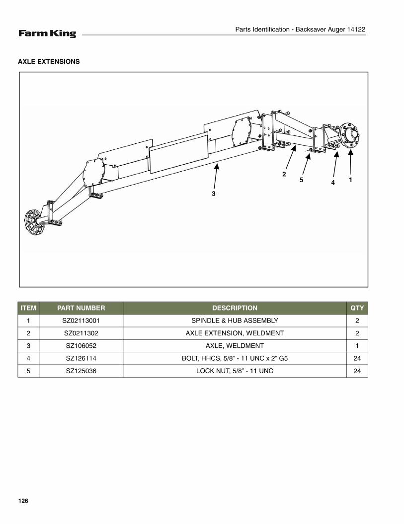
Parts Identification - Backsaver Auger 14122
AXLE EXTENSIONS
ITEM PART NUMBER DESCRIPTION QTY
1 SZ02113001 SPINDLE & HUB ASSEMBLY 2
2 SZ0211302 AXLE EXTENSION, WELDMENT 2
3 SZ106052 AXLE, WELDMENT 1
4 SZ126114 BOLT, HHCS, 5/8” - 11 UNC x 2” G5 24
5 SZ125036 LOCK NUT, 5/8” - 11 UNC 24
3
25 4 1
126
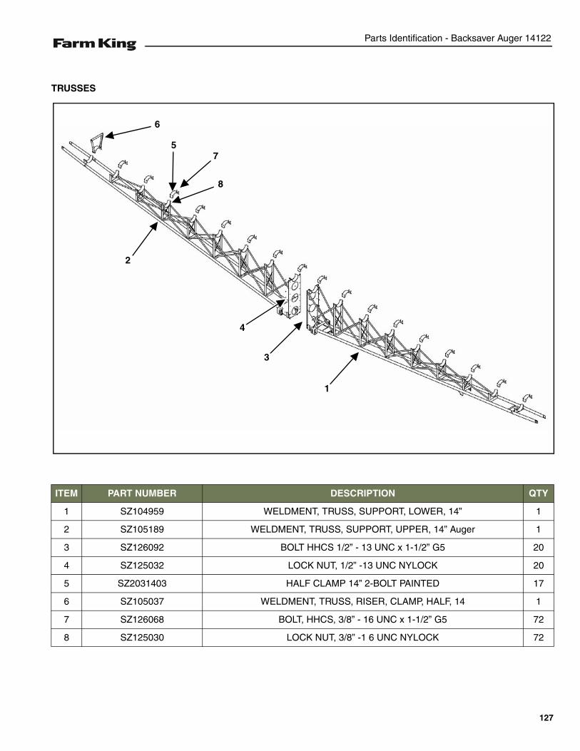
Parts Identification - Backsaver Auger 14122
TRUSSES
ITEM PART NUMBER DESCRIPTION QTY
1 SZ104959 WELDMENT, TRUSS, SUPPORT, LOWER, 14” 1
2 SZ105189 WELDMENT, TRUSS, SUPPORT, UPPER, 14” Auger 1
3 SZ126092 BOLT HHCS 1/2” - 13 UNC x 1-1/2” G5 20
4 SZ125032 LOCK NUT, 1/2” -13 UNC NYLOCK 20
5 SZ2031403 HALF CLAMP 14” 2-BOLT PAINTED 17
6 SZ105037 WELDMENT, TRUSS, RISER, CLAMP, HALF, 14 1
7 SZ126068 BOLT, HHCS, 3/8” - 16 UNC x 1-1/2” G5 72
8 SZ125030 LOCK NUT, 3/8” -1 6 UNC NYLOCK 72
6
57
8
2
1
4
3
127
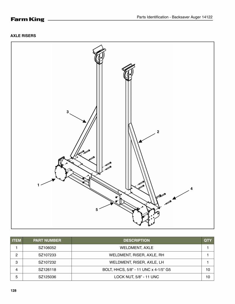
Parts Identification - Backsaver Auger 14122
AXLE RISERS
ITEM PART NUMBER DESCRIPTION QTY
1 SZ106052 WELDMENT, AXLE 1
2 SZ107233 WELDMENT, RISER, AXLE, RH 1
3 SZ107232 WELDMENT, RISER, AXLE, LH 1
4 SZ126118 BOLT, HHCS, 5/8” - 11 UNC x 4-1/5” G5 10
5 SZ125036 LOCK NUT, 5/8” - 11 UNC 10
1
5
2
4
3
128
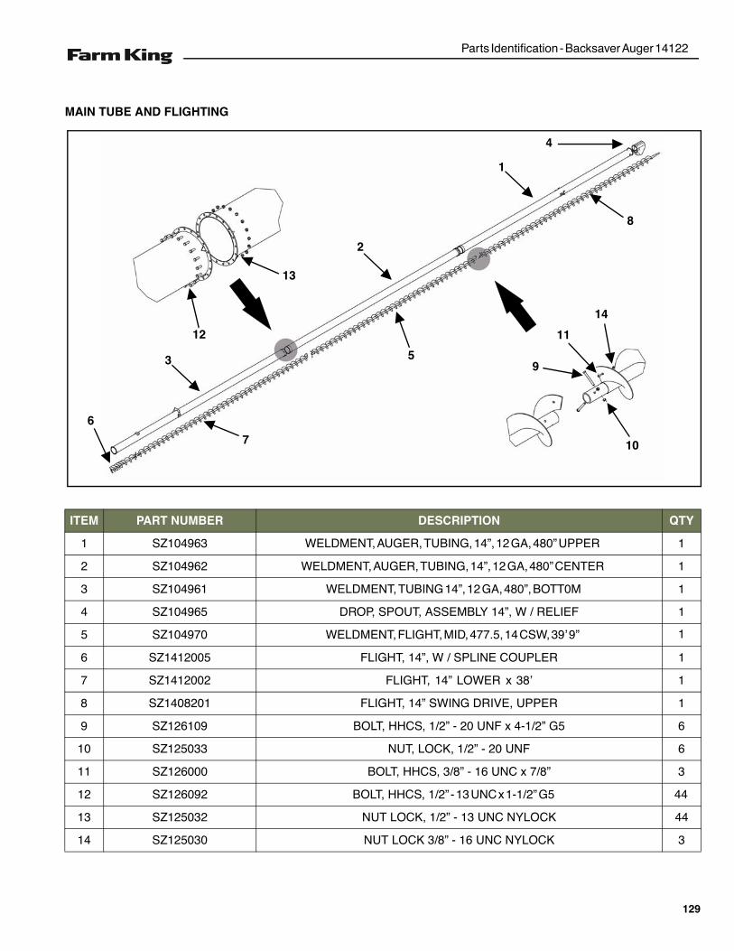
Parts Identification - Backsaver Auger 14122
MAIN TUBE AND FLIGHTING
ITEM PART NUMBER DESCRIPTION QTY
1 SZ104963 WELDMENT, AUGER, TUBING, 14”, 12 GA, 480” UPPER
2 SZ104962 WELDMENT, AUGER, TUBING, 14”, 12 GA, 480” CENTER
3 SZ104961 WELDMENT, TUBING 14”, 12 GA, 480”, BOTT0M
1
1
FEILER / W ,”41 YLBMESSA ,TUOPS ,PORD569401ZS4
5 SZ104970 WELDMENT, FLIGHT, MID, 477.5, 14 CSW, 39’ 9”
1RELPUOC ENILPS / W ,”41 ,THGILF5002141ZS6
1’83 x LOWER ”41 ,THGILF2002141ZS7
41 ,THGILF1028041ZS8 1
1
1
1
REPPU ,EVIRD GNIWS ”
65G ”2/1-4 x FNU 02 - ”2/1 ,SCHH ,TLOB901621ZS9
6FNU 02 - ”2/1 ,KCOL ,TUN330521ZS01
3”8/7 x CNU 61 - ”8/3 ,SCHH ,TLOB000621ZS11
”2/1 ,SCHH ,TLOB290621ZS21 - 13 UNC x 1-1/2” G5
44
44
KCOLYN CNU 31 - ”2/1 ,KCOL TUN230521ZS31
3KCOLYN CNU 61 - ”8/3 KCOL TUN030521ZS41
1
8
13
12
3
6
5
7
2
9
11
14
10
4
129
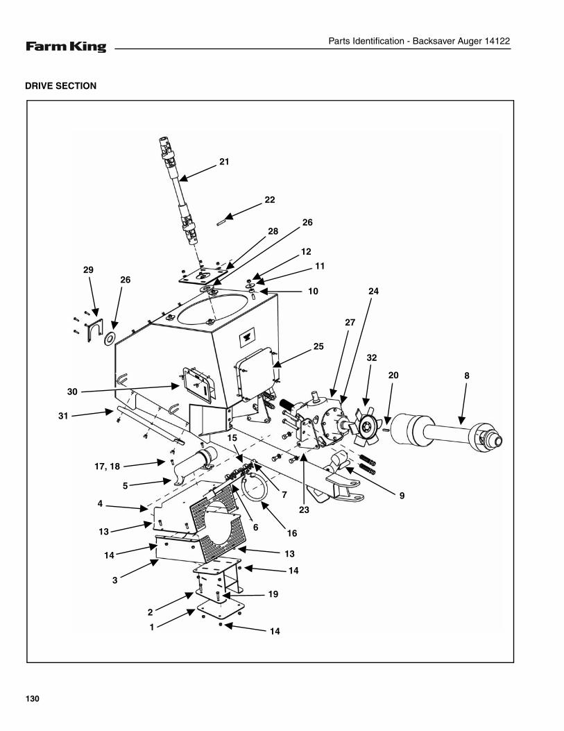
Parts Identification - Backsaver Auger 14122
DRIVE SECTION
21
22
28
12
11
25
27
20 8
97
23
26
30
2926
31
17, 18
15
6
13
16
14
19
141
2
3
4
13
14
5
24
32
10
130

Parts Identification - Backsaver Auger 14122
ITEM PART NUMBER DESCRIPTION QTY
1 SZ101997 PLATE, FAN, SHIELD, MOUNT, BOTTOM, 7 GA 1
2 SZ101937 WELDMENT, FAN, SHIELD, MOUNT, 14” 1
3 SZ103674 WELDMENT, FAN, SHIELD, BOTTOM 1
4 SZ105191 WELDMENT, FAN, SHIELD, TOP, 14” 1
5 SZ103296 OWNER’S MAUAL CONTAINER 1
6 SZ105190 HANGER, PTO, FORMED CHANNEL 1
7 SZ000180 BRACKET, HOSE SUPPORT 1
8 SZ0165545 55E CV 1-3/4” - 20-SPLINE x 1-3/4” 1
9 SZ103298 JACK, 2000 LB., DI 6620 1
10 SZ9902517 FLAT WASHER, 1/2” x 1.19” x 0.56” 4
11 SZ9941718 WASHER, FLAT, 0.53” x 2.25” 10 GA GALVANIZED 4
12 SZ12503 LOCK NUT, 1/2” - 13UNC NYLOCK 4
13 SZ126065 BOLT, HHCS, 3/8” - 16 UNC x 1” G5 18
14 SZ125030 LOCK NUT, 3/8” - 16 UNC NYLOCK 22
15 SZ103259 CLAMP, HOSE TIE-DOWN 6
16 SZ91230 STRAP, RUBBER #509-S W/S-HOOK 1
17 SZ126047 BOLT, HHCS, 5/16” -18 UNC x 1” G5 2
18 SZ125035 LOCK NUT, 5/16” -18 UNC, NYLOCK G5 2
19 SZ126068 BOLT, HHCS, 3/8” - 16 UNC x 1-1/2” G5 4
20 SZ0113820 KEY, SQ, 3/8” x 2” 1
21 SZ0161421 CV JOINT, DOUBLE, 14E, 50 DEGREE, 1-1/4 B 1
22 SZ6007025 PIN, SPL, 7/16, 2-1/2 1
23 SZ108114 PLATE, FORMED GEARBOX MOUNT 14 LH 1
24 SZ108116 PLATE, FORMED GEARBOX MOUNT 14 RH 1
25 SZ9902533 14” DRIVE SECTION ACCESS DOOR 1
26 SZ9902137 14” DRIVE SECTION GEARBOX SEAL WASHER 1
27 SZ000154 GEARBOX, 68 DEGREE 14” LOWER POINT 1
28 SZ101990 PLATE, GEARBOX SEAL DRIVE SECTION 14” 10GA 1
29 SZ9902138 14” DRIVE SECTION GEARBOX SEAL PLATE 1
30 SZ103518 DOOR, ACCESS, OFFSET GALVANIZED 1
31 SZ104489 CHANNEL, COVER DRIVE SECTION LOWER 1
32 SZ0161175 ALUMINUM FAN, 11-3/4” OD, 1-7/8” ID, 6-Blade 1
131
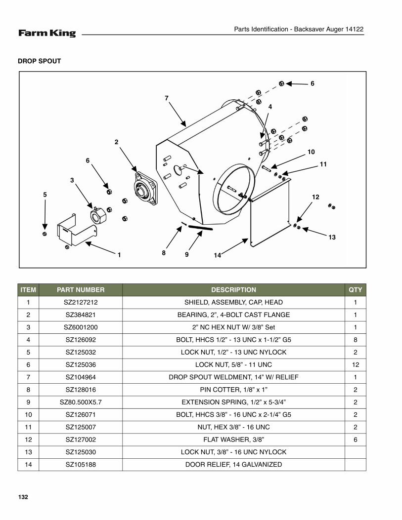
Parts Identification - Backsaver Auger 14122
DROP SPOUT
ITEM PART NUMBER DESCRIPTION QTY
1 SZ2127212 SHIELD, ASSEMBLY, CAP, HEAD 1
2 SZ384821 BEARING, 2”, 4-BOLT CAST FLANGE 1
3 SZ6001200 2” NC HEX NUT W/ 3/8” Set 1
4 SZ126092 BOLT, HHCS 1/2” - 13 UNC x 1-1/2” G5 8
5 SZ125032 LOCK NUT, 1/2” - 13 UNC NYLOCK 2
6 SZ125036 LOCK NUT, 5/8” - 11 UNC 12
7 SZ104964 DROP SPOUT WELDMENT, 14” W/ RELIEF 1
8 SZ128016 PIN COTTER, 1/8” x 1” 2
9 SZ80.500X5.7 EXTENSION SPRING, 1/2” x 5-3/4” 2
10 SZ126071 BOLT, HHCS 3/8” - 16 UNC x 2-1/4” G5 2
11 SZ125007 NUT, HEX 3/8” - 16 UNC 2
12 SZ127002 FLAT WASHER, 3/8” 6
13 SZ125030 LOCK NUT, 3/8” - 16 UNC NYLOCK
14 SZ105188 DOOR RELIEF, 14 GALVANIZED
6
10
4
11
12
13
14
7
2
6
3
5
1 8 9
132
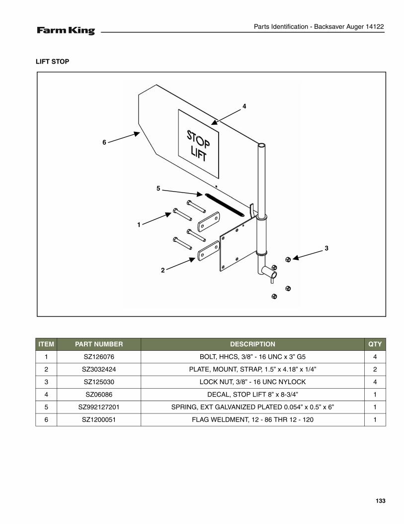
Parts Identification - Backsaver Auger 14122
LIFT STOP
ITEM PART NUMBER DESCRIPTION QTY
1 SZ126076 BOLT, HHCS, 3/8” - 16 UNC x 3” G5 4
2 SZ3032424 PLATE, MOUNT, STRAP, 1.5” x 4.18” x 1/4” 2
3 SZ125030 LOCK NUT, 3/8” - 16 UNC NYLOCK 4
4 SZ06086 DECAL, STOP LIFT 8” x 8-3/4” 1
5 SZ992127201 SPRING, EXT GALVANIZED PLATED 0.054” x 0.5” x 6” 1
6 SZ1200051 FLAG WELDMENT, 12 - 86 THR 12 - 120 1
4
6
3
2
1
5
133
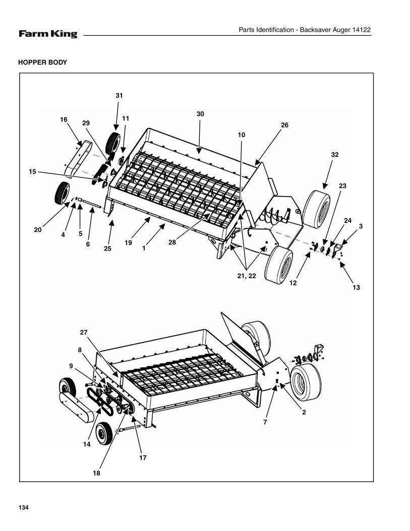
Parts Identification - Backsaver Auger 14122
HOPPER BODY
1
12
23
243
13
30
10
281925
6
5420
16 2911
72
17
27
18
14
9
8
26
21, 22
15
32
31
134
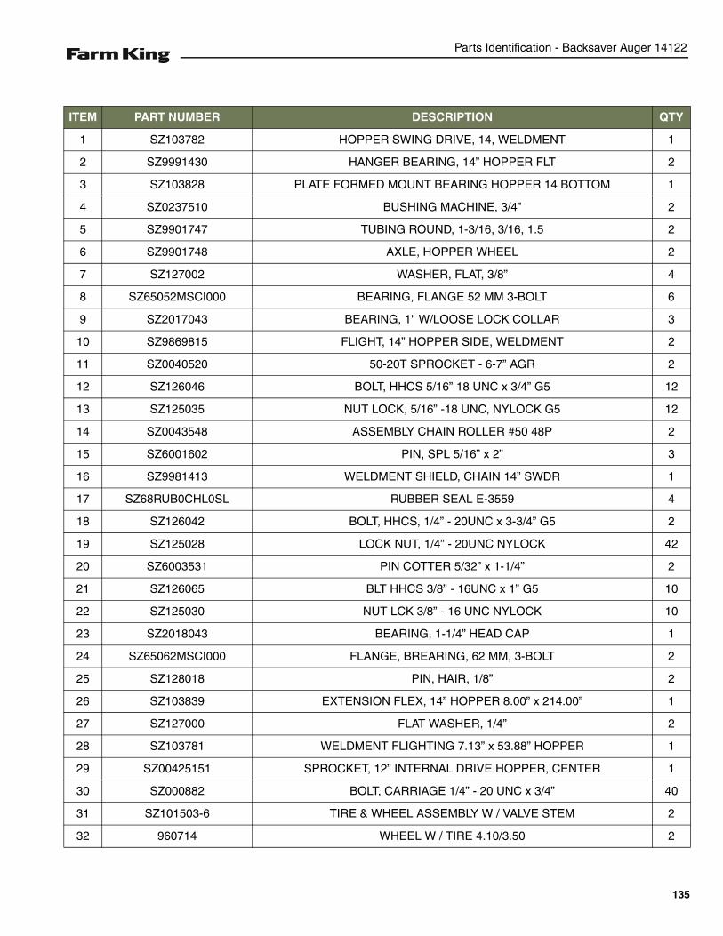
Parts Identification - Backsaver Auger 14122
ITEM PART NUMBER DESCRIPTION QTY
1 SZ103782 HOPPER SWING DRIVE, 14, WELDMENT 1
2 SZ9991430 HANGER BEARING, 14” HOPPER FLT 2
3 SZ103828 PLATE FORMED MOUNT BEARING HOPPER 14 BOTTOM 1
4 SZ0237510 BUSHING MACHINE, 3/4” 2
5 SZ9901747 TUBING ROUND, 1-3/16, 3/16, 1.5 2
6 SZ9901748 AXLE, HOPPER WHEEL 2
7 SZ127002 WASHER, FLAT, 3/8” 4
8 SZ65052MSCI000 BEARING, FLANGE 52 MM 3-BOLT 6
9 SZ2017043 BEARING, 1" W/LOOSE LOCK COLLAR 3
10 SZ9869815 FLIGHT, 14” HOPPER SIDE, WELDMENT 2
11 SZ0040520 50-20T SPROCKET - 6-7” AGR 2
12 SZ126046 BOLT, HHCS 5/16” 18 UNC x 3/4” G5 12
13 SZ125035 NUT LOCK, 5/16” -18 UNC, NYLOCK G5 12
14 SZ0043548 ASSEMBLY CHAIN ROLLER #50 48P 2
15 SZ6001602 PIN, SPL 5/16” x 2” 3
16 SZ9981413 WELDMENT SHIELD, CHAIN 14” SWDR 1
17 SZ68RUB0CHL0SL RUBBER SEAL E-3559 4
18 SZ126042 BOLT, HHCS, 1/4” - 20UNC x 3-3/4” G5 2
19 SZ125028 LOCK NUT, 1/4” - 20UNC NYLOCK 42
20 SZ6003531 PIN COTTER 5/32” x 1-1/4” 2
21 SZ126065 BLT HHCS 3/8” - 16UNC x 1” G5 10
22 SZ125030 NUT LCK 3/8” - 16 UNC NYLOCK 10
23 SZ2018043 BEARING, 1-1/4” HEAD CAP 1
24 SZ65062MSCI000 FLANGE, BREARING, 62 MM, 3-BOLT 2
25 SZ128018 PIN, HAIR, 1/8” 2
26 SZ103839 EXTENSION FLEX, 14” HOPPER 8.00” x 214.00” 1
27 SZ127000 FLAT WASHER, 1/4” 2
28 SZ103781 WELDMENT FLIGHTING 7.13” x 53.88” HOPPER 1
29 SZ00425151 SPROCKET, 12” INTERNAL DRIVE HOPPER, CENTER 1
30 SZ000882 BOLT, CARRIAGE 1/4” - 20 UNC x 3/4” 40
31 SZ101503-6 TIRE & WHEEL ASSEMBLY W / VALVE STEM 2
32 960714 WHEEL W / TIRE 4.10/3.50 2
135
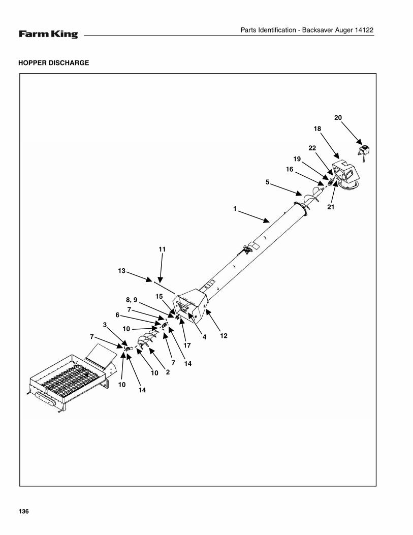
Parts Identification - Backsaver Auger 14122
HOPPER DISCHARGE
20
18
22
19
16
21
5
1
11
13
12417
1014
3
7
158, 9
2147
7
10
6
10
136
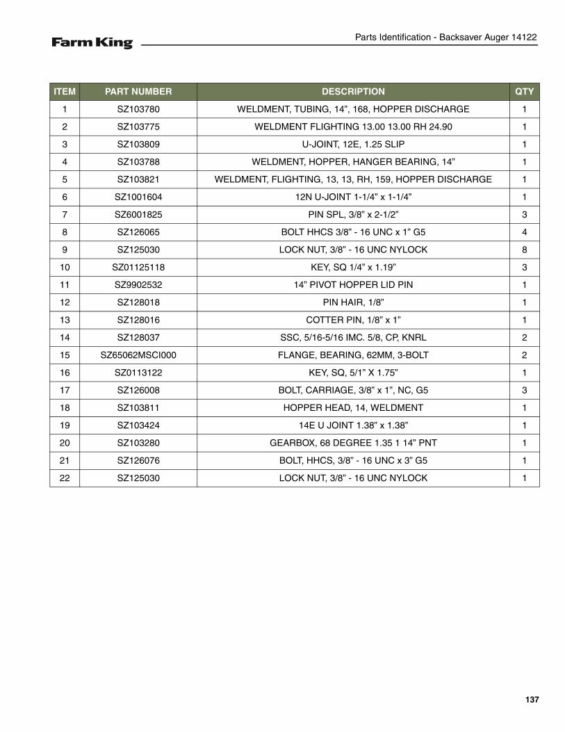
Parts Identification - Backsaver Auger 14122
ITEM PART NUMBER DESCRIPTION QTY
1 SZ103780 WELDMENT, TUBING, 14”, 168, HOPPER DISCHARGE 1
2 SZ103775 WELDMENT FLIGHTING 13.00 13.00 RH 24.90 1
3 SZ103809 U-JOINT, 12E, 1.25 SLIP 1
4 SZ103788 WELDMENT, HOPPER, HANGER BEARING, 14” 1
5 SZ103821 WELDMENT, FLIGHTING, 13, 13, RH, 159, HOPPER DISCHARGE 1
6 SZ1001604 12N U-JOINT 1-1/4” x 1-1/4” 1
7 SZ6001825 PIN SPL, 3/8” x 2-1/2” 3
8 SZ126065 BOLT HHCS 3/8” - 16 UNC x 1” G5 4
9 SZ125030 LOCK NUT, 3/8” - 16 UNC NYLOCK 8
10 SZ01125118 KEY, SQ 1/4” x 1.19” 3
11 SZ9902532 14” PIVOT HOPPER LID PIN 1
12 SZ128018 PIN HAIR, 1/8” 1
13 SZ128016 COTTER PIN, 1/8” x 1” 1
14 SZ128037 SSC, 5/16-5/16 IMC. 5/8, CP, KNRL 2
15 SZ65062MSCI000 FLANGE, BEARING, 62MM, 3-BOLT 2
16 SZ0113122 KEY, SQ, 5/1” X 1.75” 1
17 SZ126008 BOLT, CARRIAGE, 3/8” x 1”, NC, G5 3
18 SZ103811 HOPPER HEAD, 14, WELDMENT 1
19 SZ103424 14E U JOINT 1.38” x 1.38” 1
20 SZ103280 GEARBOX, 68 DEGREE 1.35 1 14” PNT 1
21 SZ126076 BOLT, HHCS, 3/8” - 16 UNC x 3” G5 1
22 SZ125030 LOCK NUT, 3/8” - 16 UNC NYLOCK 1
137
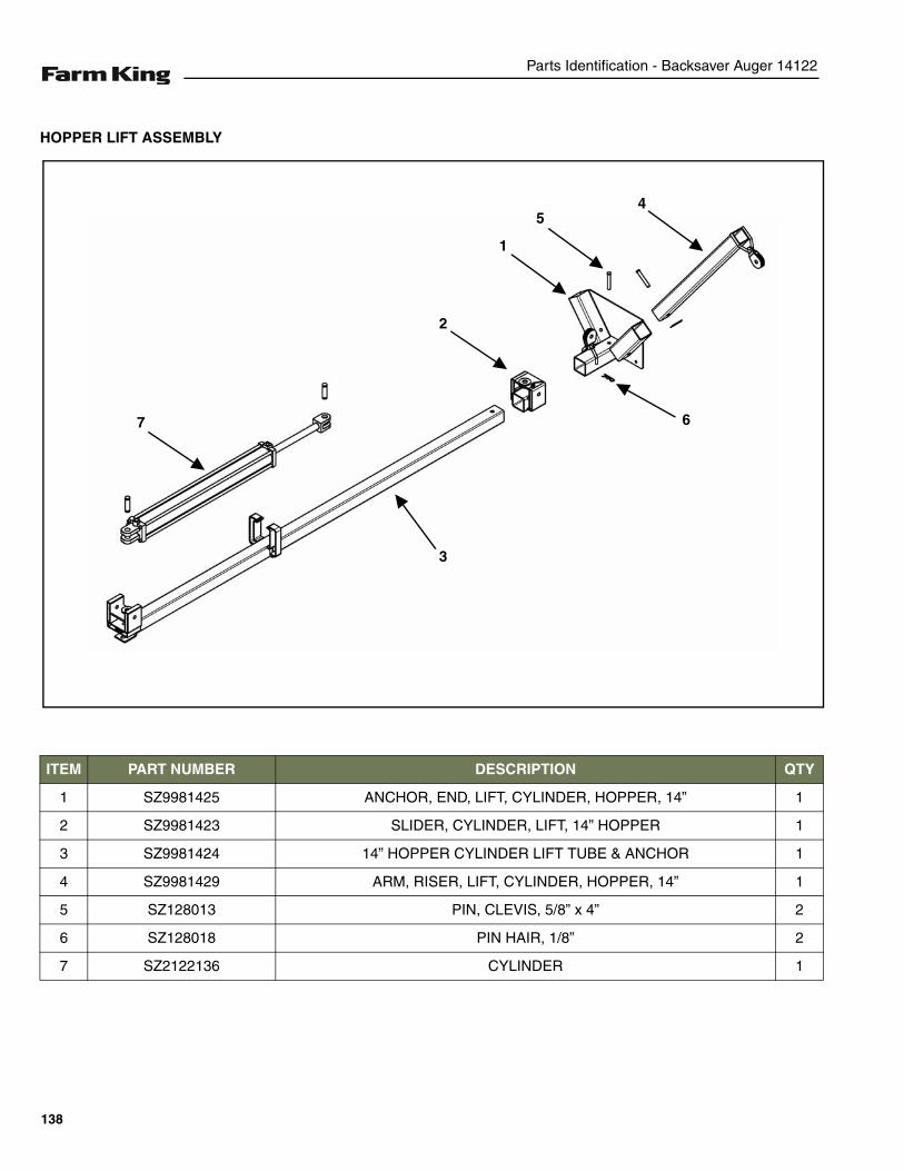
Parts Identification - Backsaver Auger 14122
HOPPER LIFT ASSEMBLY
ITEM PART NUMBER DESCRIPTION QTY
1 SZ9981425 ANCHOR, END, LIFT, CYLINDER, HOPPER, 14” 1
2 SZ9981423 SLIDER, CYLINDER, LIFT, 14” HOPPER 1
3 SZ9981424 14” HOPPER CYLINDER LIFT TUBE & ANCHOR 1
4 SZ9981429 ARM, RISER, LIFT, CYLINDER, HOPPER, 14” 1
5 SZ128013 PIN, CLEVIS, 5/8” x 4” 2
6 SZ128018 PIN HAIR, 1/8” 2
7 SZ2122136 CYLINDER 1
45
1
2
7
3
6
138
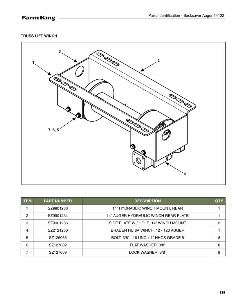
Parts Identification - Backsaver Auger 14122
TRUSS LIFT WINCH
ITEM PART NUMBER DESCRIPTION QTY
1 SZ9901233 14” HYDRAULIC WINCH MOUNT, REAR 1
2 SZ9901234 14” AUGER HYDRAULIC WINCH REAR PLATE 1
3 SZ9901235 SIDE PLATE W / HOLE, 14” WINCH MOUNT 2
4 SZ2121250 BRADEN HU 8A WINCH, 12 - 120 AUGER 1
5 SZ126065 BOLT, 3/8” - 16 UNC x 1” HHCS GRADE 5 8
6 SZ127002 FLAT WASHER, 3/8” 8
7 SZ127009 LOCK WASHER, 3/8” 8
4
7, 6, 5
1 2
3
139
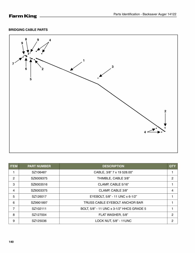
Parts Identification - Backsaver Auger 14122
BRIDGING CABLE PARTS
ITEM PART NUMBER DESCRIPTION QTY
1 SZ106487 CABLE, 3/8” 7 x 19 528.00” 1
2 SZ6009375 THIMBLE, CABLE 3/8” 2
3 SZ6003516 CLAMP, CABLE 5/16” 1
4 SZ6003375 CLAMP, CABLE 3/8” 4
5 SZ126017 EYEBOLT, 5/8” - 11 UNC x 6-1/2” 1
6 SZ9901897 TRUSS CABLE EYEBOLT ANCHOR BAR 1
7 SZ102111 BOLT, 5/8” - 11 UNC x 3-1/2” HHCS GRADE 5 1
8 SZ127004 FLAT WASHER, 5/8” 2
9 SZ125036 LOCK NUT, 5/8” - 11UNC 2
4
5
1
2
73
6
4
2
98 9
140
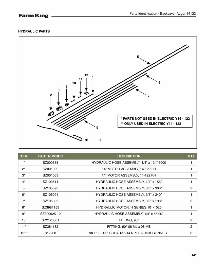
Parts Identification - Backsaver Auger 14122
HYDRAULIC PARTS
ITEM PART NUMBER DESCRIPTION QTY
1* SZ000688 HYDRAULIC HOSE ASSEMBLY, 1/4” x 124” 3000 1
2* SZ001062 14” MOTOR ASSEMBLY, 14-122 LH 1
3* SZ001063 14” MOTOR ASSEMBLY, 14-122 RH 1
4* SZ100511 HYDRAULIC HOSE ASSEMBLY, 1/4” x 156” 1
5 SZ105093 HYDRAULIC HOSE ASSEMBLY, 3/8” x 360” 2
6* SZ105094 HYDRAULIC HOSE ASSEMBLY, 3/8” x 240” 1
7* SZ105095 HYDRAULIC HOSE ASSEMBLY, 3/8” x 198” 3
8* SZ3981155 HYDRAULIC MOTOR, H SERIES 101-1026 1
9* SZ300925-12 HYDRAULIC HOSE ASSEMBLY, 1/4” x 55.00” 1
10 SZ2123801 FITTING, 90° 2
11* SZ384132 FITTING, 90° 08 MJ x 08 MB 2
12** 812208 NIPPLE, 1/2” BODY 1/2”-14 NPTF QUICK CONNECT 6
4
5
1
2 7
3
6
9
810
1112
* PARTS NOT USED IN ELECTRIC Y14 - 122
** ONLY USED IN ELECTRIC Y14 - 122
141
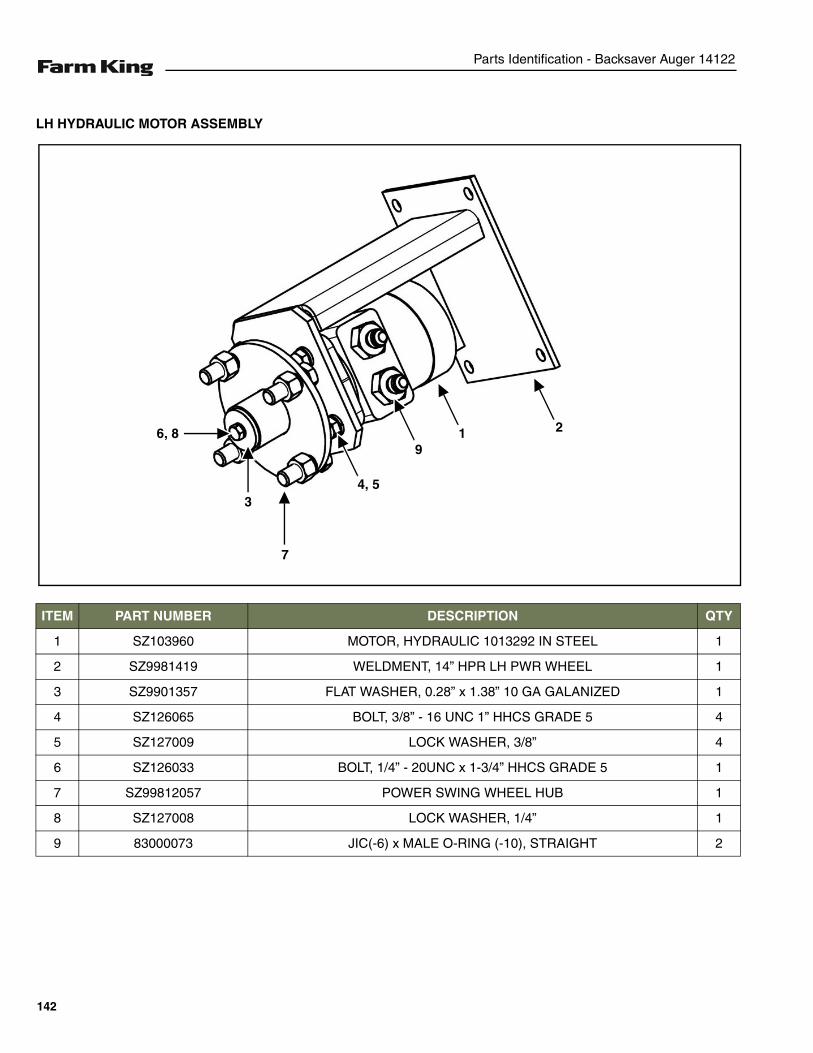
Parts Identification - Backsaver Auger 14122
LH HYDRAULIC MOTOR ASSEMBLY
ITEM PART NUMBER DESCRIPTION QTY
1 SZ103960 MOTOR, HYDRAULIC 1013292 IN STEEL 1
2 SZ9981419 WELDMENT, 14” HPR LH PWR WHEEL 1
3 SZ9901357 FLAT WASHER, 0.28” x 1.38” 10 GA GALANIZED 1
4 SZ126065 BOLT, 3/8” - 16 UNC 1” HHCS GRADE 5 4
5 SZ127009 LOCK WASHER, 3/8” 4
6 SZ126033 BOLT, 1/4” - 20UNC x 1-3/4” HHCS GRADE 5 1
7 SZ99812057 POWER SWING WHEEL HUB 1
8 SZ127008 LOCK WASHER, 1/4” 1
9 83000073 JIC(-6) x MALE O-RING (-10), STRAIGHT 2
7
3
6, 8
4, 5
91 2
142
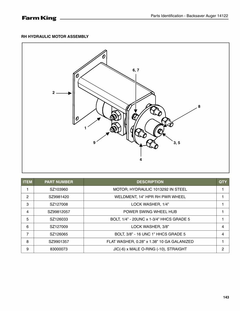
Parts Identification - Backsaver Auger 14122
RH HYDRAULIC MOTOR ASSEMBLY
ITEM PART NUMBER DESCRIPTION QTY
1 SZ103960 MOTOR, HYDRAULIC 1013292 IN STEEL 1
2 SZ9981420 WELDMENT, 14” HPR RH PWR WHEEL 1
3 SZ127008 LOCK WASHER, 1/4” 1
4 SZ99812057 POWER SWING WHEEL HUB 1
5 SZ126033 BOLT, 1/4” - 20UNC x 1-3/4” HHCS GRADE 5 1
6 SZ127009 LOCK WASHER, 3/8” 4
7 SZ126065 BOLT, 3/8” - 16 UNC 1” HHCS GRADE 5 4
8 SZ9901357 FLAT WASHER, 0.28” x 1.38” 10 GA GALANIZED 1
9 83000073 JIC(-6) x MALE O-RING (-10), STRAIGHT 2
1
2
6, 7
9
8
4
3, 5
143

Parts Identification - Backsaver Auger 14122
144
Specifications - Backsaver Auger 14122
SPECIFICATIONS
SPECIFICATIONS . . . . . . . . . . . . . . . . . . . . . . . . . . . . . . . . . . . . . . . . . . . . . . . . . . . . . . . . . . . . . 147Dimensions . . . . . . . . . . . . . . . . . . . . . . . . . . . . . . . . . . . . . . . . . . . . . . . . . . . . . . . . . . . . . . . . 147Performance . . . . . . . . . . . . . . . . . . . . . . . . . . . . . . . . . . . . . . . . . . . . . . . . . . . . . . . . . . . . . . . 148
HARDWARE TORQUE VALUES . . . . . . . . . . . . . . . . . . . . . . . . . . . . . . . . . . . . . . . . . . . . . . . . . . 149Metric Chart . . . . . . . . . . . . . . . . . . . . . . . . . . . . . . . . . . . . . . . . . . . . . . . . . . . . . . . . . . . . . . . 149Imperial Chart . . . . . . . . . . . . . . . . . . . . . . . . . . . . . . . . . . . . . . . . . . . . . . . . . . . . . . . . . . . . . . 150
HYDRAULIC CONNECTION SPECIFICATIONS . . . . . . . . . . . . . . . . . . . . . . . . . . . . . . . . . . . . . .151O-Ring Fitting (Straight Thread) . . . . . . . . . . . . . . . . . . . . . . . . . . . . . . . . . . . . . . . . . . . . . . . .151O-ring Face Seal Connection . . . . . . . . . . . . . . . . . . . . . . . . . . . . . . . . . . . . . . . . . . . . . . . . . . 151Flare Fitting . . . . . . . . . . . . . . . . . . . . . . . . . . . . . . . . . . . . . . . . . . . . . . . . . . . . . . . . . . . . . . . . 151Port Seal (O-ring Boss) Fitting . . . . . . . . . . . . . . . . . . . . . . . . . . . . . . . . . . . . . . . . . . . . . . . . . 151Tubelines And Hoses . . . . . . . . . . . . . . . . . . . . . . . . . . . . . . . . . . . . . . . . . . . . . . . . . . . . . . . . 151
145

Specifications - Backsaver Auger 14122
146
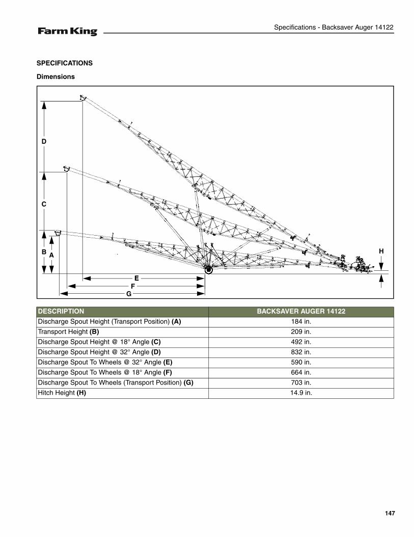
Specifications - Backsaver Auger 14122
SPECIFICATIONS
Dimensions
DESCRIPTION BACKSAVER AUGER 14122
Discharge Spout Height (Transport Position) (A) 184 in.
Transport Height (B) 209 in.
Discharge Spout Height @ 18° Angle (C) 492 in.
Discharge Spout Height @ 32° Angle (D) 832 in.
Discharge Spout To Wheels @ 32° Angle (E) 590 in.
Discharge Spout To Wheels @ 18° Angle (F) 664 in.
Discharge Spout To Wheels (Transport Position) (G) 703 in.
Hitch Height (H) 14.9 in.
AAB
C
D
EEF
G
H
147
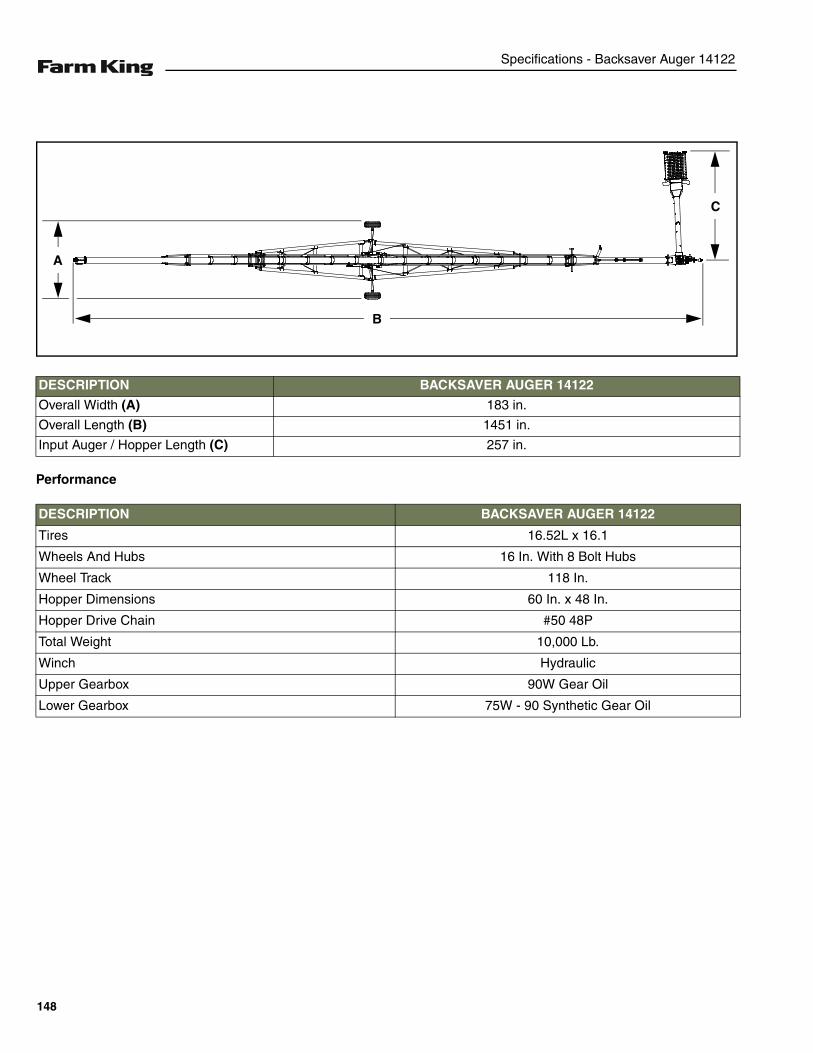
Specifications - Backsaver Auger 14122
Performance
DESCRIPTION BACKSAVER AUGER 14122
Overall Width (A) 183 in.
Overall Length (B) 1451 in.
Input Auger / Hopper Length (C) 257 in.
DESCRIPTION BACKSAVER AUGER 14122
Tires 16.52L x 16.1
Wheels And Hubs 16 In. With 8 Bolt Hubs
Wheel Track 118 In.
Hopper Dimensions 60 In. x 48 In.
Hopper Drive Chain #50 48P
Total Weight 10,000 Lb.
Winch Hydraulic
Upper Gearbox 90W Gear Oil
Lower Gearbox 75W - 90 Synthetic Gear Oil
A
C
B
148
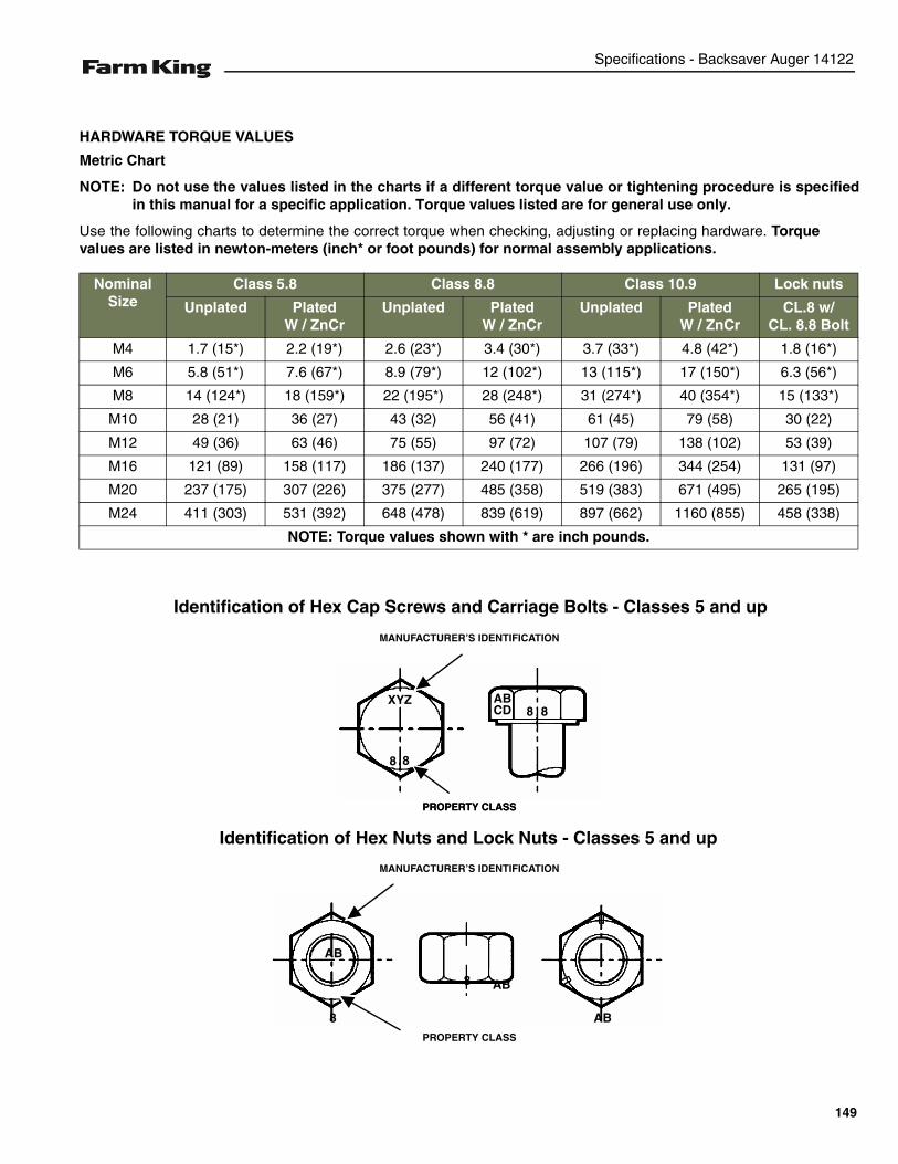
Specifications - Backsaver Auger 14122
HARDWARE TORQUE VALUES
Metric Chart
NOTE: Do not use the values listed in the charts if a different torque value or tightening procedure is specifiedin this manual for a specific application. Torque values listed are for general use only.
Use the following charts to determine the correct torque when checking, adjusting or replacing hardware. Torquevalues are listed in newton-meters (inch* or foot pounds) for normal assembly applications.
Nominal Size
Class 5.8 Class 8.8 Class 10.9 Lock nuts
Unplated PlatedW / ZnCr
Unplated PlatedW / ZnCr
Unplated PlatedW / ZnCr
CL.8 w/CL. 8.8 Bolt
M4 1.7 (15*) 2.2 (19*) 2.6 (23*) 3.4 (30*) 3.7 (33*) 4.8 (42*) 1.8 (16*)
M6 5.8 (51*) 7.6 (67*) 8.9 (79*) 12 (102*) 13 (115*) 17 (150*) 6.3 (56*)
M8 14 (124*) 18 (159*) 22 (195*) 28 (248*) 31 (274*) 40 (354*) 15 (133*)
M10 28 (21) 36 (27) 43 (32) 56 (41) 61 (45) 79 (58) 30 (22)
M12 49 (36) 63 (46) 75 (55) 97 (72) 107 (79) 138 (102) 53 (39)
M16 121 (89) 158 (117) 186 (137) 240 (177) 266 (196) 344 (254) 131 (97)
M20 237 (175) 307 (226) 375 (277) 485 (358) 519 (383) 671 (495) 265 (195)
M24 411 (303) 531 (392) 648 (478) 839 (619) 897 (662) 1160 (855) 458 (338)
NOTE: Torque values shown with * are inch pounds.
Identification of Hex Cap Screws and Carriage Bolts - Classes 5 and up
XYZ
8 8
8 8ABCD
MANUFACTURER’S IDENTIFICATION
PROPERTY CLASS
Identification of Hex Nuts and Lock Nuts - Classes 5 and up
PROPERTY CLASS
MANUFACTURER’S IDENTIFICATION
PROPERTY CLASS
AB
AB8
8 AB
149
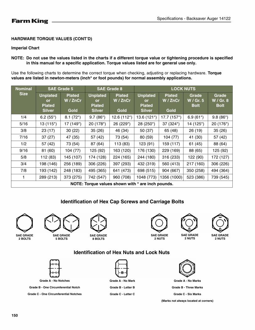
Specifications - Backsaver Auger 14122
HARDWARE TORQUE VALUES (CONT’D)
Imperial Chart
NOTE: Do not use the values listed in the charts if a different torque value or tightening procedure is specifiedin this manual for a specific application. Torque values listed are for general use only.
Use the following charts to determine the correct torque when checking, adjusting or replacing hardware. Torquevalues are listed in newton-meters (inch* or foot pounds) for normal assembly applications.
Nominal Size
SAE Grade 5 SAE Grade 8 LOCK NUTS
Unplatedor
Plated Silver
PlatedW / ZnCr
Gold
Unplatedor
Plated Silver
PlatedW / ZnCr
Gold
Unplatedor
Plated Silver
PlatedW / ZnCr
Gold
GradeW / Gr. 5
Bolt
GradeW / Gr. 8
Bolt
1/4 6.2 (55*) 8.1 (72*) 9.7 (86*) 12.6 (112*) 13.6 (121*) 17.7 (157*) 6.9 (61*) 9.8 (86*)
5/16 13 (115*) 17 (149*) 20 (178*) 26 (229*) 28 (250*) 37 (324*) 14 (125*) 20 (176*)
3/8 23 (17) 30 (22) 35 (26) 46 (34) 50 (37) 65 (48) 26 (19) 35 (26)
7/16 37 (27) 47 (35) 57 (42) 73 (54) 80 (59) 104 (77) 41 (30) 57 (42)
1/2 57 (42) 73 (54) 87 (64) 113 (83) 123 (91) 159 (117) 61 (45) 88 (64)
9/16 81 (60) 104 (77) 125 (92) 163 (120) 176 (130) 229 (169) 88 (65) 125 (92)
5/8 112 (83) 145 (107) 174 (128) 224 (165) 244 (180) 316 (233) 122 (90) 172 (127)
3/4 198 (146) 256 (189) 306 (226) 397 (293) 432 (319) 560 (413) 217 (160) 306 (226)
7/8 193 (142) 248 (183) 495 (365) 641 (473) 698 (515) 904 (667) 350 (258) 494 (364)
1 289 (213) 373 (275) 742 (547) 960 (708) 1048 (773) 1356 (1000) 523 (386) 739 (545)
NOTE: Torque values shown with * are inch pounds.
Identification of Hex Cap Screws and Carriage Bolts
Identification of Hex Nuts and Lock Nuts
SAE GRADE 2 BOLTS
SAE GRADE 5 BOLTS
SAE GRADE 8 BOLTS
SAE GRADE 2 NUTS
SAE GRADE 2 NUTS
SAE GRADE 2 NUTS
B
Grade A - No Notches
Grade B - One Circumferential Notch
Grade C - One Circumferential Notches
Grade A - No Mark
Grade B - Letter B
Grade C - Letter C
Grade A - No Marks
Grade B - Three Marks
Grade C - Six Marks
(Marks not always located at corners)
150

Specifications - Backsaver Auger 14122
HYDRAULIC CONNECTION SPECIFICATIONS
O-Ring Fitting (Straight Thread)
Lubricate the O-ring before installing the fitting. Loosenthe jam nut and install the fitting. Tighten the jam nut untilthe washer is tight against the surface.
O-ring Face Seal Connection
Figure 199
When the fitting is tightened, you can feel when the fittingis tight to eliminate leakage caused by under or overtorqued fittings. Use petroleum jelly to hold the O-ring inposition until the fittings are assembled.
Flare Fitting
Figure 200
Tighten until the nut makes contact with the seat. Use thechart [Figure 200] to find the correct tightness needed.
NOTE: If the fitting leaks, disconnect and inspect theseat area for damage.
Port Seal (O-ring Boss) Fitting
Figure 201
NOTE: Port seal and nut, washer and O-ring (O-ringBoss) fittings use the same tightening torquevalve chart.
If a torque wrench cannot be used, use the followingmethod.
Tighten the nut until it just makes metal to metal contact,you can feel the resistance.
Tighten the nut with a wrench no more than one hex flatmaximum.
Do not over tighten the port seal fitting.
NOTE: If a torque wrench cannot be used, use thehex flat tightening method as an approximateguideline.
NOTE: Port seal fittings are not recommended in allapplications. Use O-ring boss fittings in theseapplications.
Tubelines And Hoses
Replace any tubelines that are bent or flattened. They willrestrict flow, which will slow hydraulic action and causeheat.
Replace hoses which show signs of wear, damage orweather cracked rubber.
Always use two wrenches when loosening and tighteninghose or tubeline fittings.
O-ring Face Seal Tightening TorqueTubeline O.D. Thread Size N•m (ft-lb)
1/4” 9/16” - 18 13 (18)3/8” 11/16” - 16 22 (30)1/2” 13/16” - 16 40 (54)5/8” 1” - 14 60 (81)3/4” 1-3/16” - 12 84 (114)7/8” 1-3/16” - 12 98 (133)1” 1-7/16” - 12 118 (160)
1-1/4” 1-11/16” - 12 154 (209)
1-1/2” 2” - 12 163 (221)
Flare Fitting Tightening Torque
Tubeline O.D. Thread Size N•m (ft-lb)
1/4” 7/16” - 20 13 (18)
5/16” 1/2” - 20 17 (23)
3/8” 9/16” - 18 22 (30)
1/2” 3/4” - 16 40 (54)
5/8” 7/8” - 14 60 (81)
3/4” 1-1/16” - 12 84 (114)
7/8” 1-3/16” - 12 98 (133)
1” 1-5/16” - 12 118 (160)
1-1/4” 1-5/8” - 12 154 (209)
1-1/2” 1-7/8” - 12 163 (221)
2” 2-1/2” - 12 252 (342)
Port Seal And O-ring Boss Tightening Torque
Tubeline O.D. Thread Size N•m (ft-lb)
1/4” 7/16” - 20 13 (18)
3/8” 9/16” - 18 22 (30)
1/2” 3/4” -1 6 40 (54)
5/8” 7/8” - 14 60 (81)
3/4” 1-1/16” - 12 84 (114)
7/8” 1-3/16” - 12 98 (133)
1” 1-5/16” - 12 118 (160)
1-1/8” 1-7/16” - 12 154 (209)
1-1/4” 1-5/8” - 12 163 (221)
151

Specifications - Backsaver Auger 14122
152

Warranty - Backsaver Auger 14122
WARRANTY
WARRANTY . . . . . . . . . . . . . . . . . . . . . . . . . . . . . . . . . . . . . . . . . . . . . . . . . . . . . . . . . . . . . . . . . . 155
153

Warranty - Backsaver Auger 14122
154
Warranty - Backsaver Auger 14122
WARRANTY
Limited Warranty
BASE LIMITED WARRANTY
Farm King provides this warranty only to original retail purchasers of its products. Farm King warrants to suchpurchasers that all Farm King manufactured parts and components used and serviced as provided for in theOperator’s Manual shall be free from defects in materials and workmanship for a period following delivery tothe original retail purchaser of two (2) years. This limited warranty applies only to those parts and componentsmanufactured by Farm King. Parts and components manufactured by others are subject to theirmanufacturer’s warranties, if any.
Farm King will fulfill this limited warranty by, at its option, repairing or replacing any covered part that isdefective or is the result of improper workmanship, provided that the part is returned to Farm King within thirty(30) days of the date that such defect or improper workmanship is, or should have been, discovered. Partsmust be returned through the selling Farm King Dealer and the buyer must prepay transportation charges.
Farm King will not be responsible for repairs or replacements that are necessitated, in whole or part, by theuse of parts not manufactured by or obtained from Farm King. Under no circumstances are component partswarranted against normal wear and tear. There is no warranty on product pump seals, product pump bearings,rubber product hoses, pressure gauges, or other components that require replacement as part of normalmaintenance.
REPAIR PARTS LIMITED WARRANTY
Farm King warrants genuine Farm King replacement parts purchased after the expiration of the Farm KingLimited Warranty, and used and serviced as provided for in the Operator’s Manual, to be free from defects inmaterials or workmanship for a period of thirty (30) days from the invoice date for the parts. Farm King willfulfill this limited warranty by, at its option, repairing or replacing any covered part that is defective or is theresult of improper workmanship, provided that the part is returned to Farm King within thirty (30) days of thedate that such defect or improper workmanship is, or should have been, discovered. Such parts must beshipped to the Farm King factory at the purchaser’s expense.
WHAT IS NOT COVERED
Under no circumstances does this limited warranty cover any components or parts that have been subject tothe following: negligence; alteration or modification not approved by Farm King; misuse; improper storage;lack of reasonable and proper maintenance, service, or repair; normal wear; damage from failure to followoperating instructions; accident; and/or repairs that have been made with parts other than thosemanufactured, supplied, and or authorized by Farm King.
AUTHORIZED DEALER AND LABOR COSTS
Repairs eligible for labor under this limited warranty must be made by Farm King or an authorized Farm Kingdealer. Farm King retains the exclusive discretion to determine whether it will pay labor costs for warrantyrepairs or replacements, and the amount of such costs that it will pay and the time in which the repairs will bemade. If Farm King determines that it will pay labor costs for warranty work, it will do so by issuing a credit tothe dealer’s or distributor’s account. Farm King will not approve or pay invoices sent for repairs that Farm Kinghas not previously approved. Warranty service does not extend the original term of this limited warranty.
155
Warranty - Backsaver Auger 14122
Limited Warranty
WARRANTY REQUIREMENTS
To be covered by warranty, each new product must be registered with Farm King within thirty (30) days ofdelivery to original retail purchaser. If the customer decides to purchase replacement components before thewarranty disposition of such components is determined, Farm King will bill the customer for suchcomponents and then credit the replacement invoice for those components later determined to be covered bythis limited warranty. Any such replacement components that are determined not be covered by this limitedwarranty will be subject to the terms of the invoice and shall be paid for by the purchaser.
EXCLUSIVE EFFECT OF WARRANTY AND LIMITATION OF LIABILITY
TO THE EXTENT PERMITTED BY LAW, FARM KING DISCLAIMS ANY WARRANTIES, REPRESENTATIONS, ORPROMISES, EXPRESS OR IMPLIED, AS TO THE QUALITY, PERFORMANCE, OR FREEDOM FROM DEFECT OFTHE COMPONENTS AND PARTS COVERED BY THIS WARRANTY AND NOT SPECIFICALLY PROVIDED FORHEREIN.
TO THE EXTENT PERMITTED BY LAW, FARM KING DISCLAIMS ANY IMPLIED WARRANTIES OFMERCHANTABILITY AND FITNESS FOR A PARTICULAR PURPOSE ON ITS PRODUCTS COVERED HEREIN,AND DISCLAIMS ANY RELIANCE BY THE PURCHASER ON FARM KING’S SKILL OR JUDGMENT TO SELECTOR FURNISH GOODS FOR ANY PARTICULAR PURPOSE. THE PURCHASER’S ONLY AND EXCLUSIVEREMEDIES IN CONNECTION WITH THE BREACH OR PERFORMANCE OF ANY WARRANTY ON FARM KING’SPRODUCTS ARE THOSE SET FORTH HEREIN. IN NO EVENT SHALL FARM KING BE LIABLE FOR INCIDENTALOR CONSEQUENTIAL DAMAGES (INCLUDING, BY WAY OF EXAMPLE ONLY AND NOT LIMITATION, LOSS OFCROPS, LOSS OF PROFITS OR REVENUE, OTHER COMMERCIAL LOSSES, INCONVENIENCE, OR COST OFREPLACEMENT OF RENTAL EQUIPMENT). IN NO EVENT SHALL FARM KING’S CONTRACT OR WARRANTYLIABILITY EXCEED THE PURCHASE PRICE OF THE PRODUCT. (Note that some states do not allow limitationson how long an implied warranty lasts or the exclusion or limitation of incidental or consequential damages,so the above limitations and exclusion may not apply to you.) This warranty gives you specific legal rights andyou may also have other rights, which vary from state to state.
Farm King neither assumes nor authorizes any person or entity, including its selling representatives, toassume any other obligations or liability in connections with the sale of covered equipment, or to make anyother warranties, representations, or promises, express or implied, as to the quality, performance, or freedomfrom defect of the components and parts covered herein. No one is authorized to alter, modify, or enlarge thislimited warranty, or its exclusions, limitations and reservations.
Corrections of defects and improper workmanship in the manner, and for the applicable time periods, providedfor herein shall constitute fulfillment of all responsibilities of Farm King to the purchaser, and Farm King shallnot be liable in negligence, contract, or on any other basis with respect to the subject equipment.
This limited warranty is subject to any existing conditions of supply which may directly affect Farm King’sability to obtain materials or manufacturer replacement parts.
Buhler Industries Inc. reserves the right to make improvements in design or changes in specifications to itsproducts at anytime, without incurring any obligation to owners of units previously sold.
156
Alphabetical Index - Backsaver Auger 14122
ALPHABETICAL INDEX
8 BOLT HUB . . . . . . . . . . . . . . . . . . . . . . . . 119AUGER OPERATION . . . . . . . . . . . . . . . . . . 87AXLE EXTENSIONS . . . . . . . . . . . . . . . . . 126AXLE RISERS . . . . . . . . . . . . . . . . . . . . . . 128AXLE . . . . . . . . . . . . . . . . . . . . . . . . . . . . . 114BASE GROUP . . . . . . . . . . . . . . . . . . . . . . . 30BRIDGING CABLE PARTS . . . . . . . . . . . . 140DRIVE SECTION . . . . . . . . . . . . . . . . . . . . 130DROP SPOUT . . . . . . . . . . . . . . . . . . . . . . 132EQUIPMENT DECALS AND SIGNS . . . . . . 24EQUIPMENT IDENTIFICATION . . . . . . . . . . . 8FIRE PREVENTION . . . . . . . . . . . . . . . . . . . 14GENERAL ASSEMBLY INFORMATION . . . 29GENERAL INFORMATION . . . . . . . . . . . . 119GENERAL OPERATION INFORMATION . . . 75HARDWARE TORQUE VALUES . . . . . . . . 149HOPPER BODY . . . . . . . . . . . . . . . . . . . . . 134HOPPER DISCHARGE . . . . . . . . . . . . . . . 136HOPPER LIFT ASSEMBLY . . . . . . . . . . . . 138HYDRAULIC ASSEMBLY . . . . . . . . . . . . . . . 65HYDRAULIC CONNECTION SPECIFICATIONS . . . . . . . . . . . . . . . . . . . 151HYDRAULIC PARTS . . . . . . . . . . . . . . . . . 141INITIAL SET-UP . . . . . . . . . . . . . . . . . . . . . . 79LH HYDRAULIC MOTOR ASSEMBLY . . . . 142LIFT STOP . . . . . . . . . . . . . . . . . . . . . . . . . 133LOADING GRAIN INTO THE HOPPER . . . . 95LOWER GEARBOX #SZ000154 . . . . . . . . 120LUBRICATION . . . . . . . . . . . . . . . . . . . . . . 109MAIN TUBE AND FLIGHTING . . . . . . . . . . 129OPERATING SAFETY ZONE . . . . . . . . . . . . 16OWNER’S INFORMATION . . . . . . . . . . . . . . . 7RH HYDRAULIC MOTOR ASSEMBLY . . . . 143SAFETY INSTRUCTIONS . . . . . . . . . . . . . . 11SAFETY SIGN (DECAL) INSTALLATION . 115SAFETY SIGN-OFF FORM . . . . . . . . . . . . . 26SAFETY SIGNS (DECALS) . . . . . . . . . . . . . 17SERVICE SCHEDULE . . . . . . . . . . . . . . . . 108SPECIFICATIONS . . . . . . . . . . . . . . . . . . . 147
STORAGE AND RETURN TO SERVICE . .116TRANSPORTING . . . . . . . . . . . . . . . . . . . . . 99TROUBLESHOOTING . . . . . . . . . . . . . . . . 107TRUSS LIFT WINCH . . . . . . . . . . . . . . . . . 139TRUSSES . . . . . . . . . . . . . . . . . . . . . . . . . . 127UNDERCARRAIGE . . . . . . . . . . . . . . . . . . 124UPPER GEARBOX #SZ103280 . . . . . . . . . 122WARRANTY REGISTRATION FORM . . . . . . 3WARRANTY . . . . . . . . . . . . . . . . . . . . . . . .155WINCH CABLE INSTALLATION . . . . . . . . . . 69
157

Alphabetical Index - Backsaver Auger 14122
158


411 Center Avenue WestSalem, SD USA 57058-0398Toll Free: 1-888-FK-80001 E-mail: [email protected]
Equipment shown is subject to change without notice.©2014 Buhler Trading Inc. Printed in Canada TSX:BUI
www.farm-king.com


