92
6990633 (1-13) Printed in U.S.A. © Bobcat Company 2013 OPERATOR AND PARTS MANUAL Disc Mower Model 4, 5, 6, 7 062013 | Rev 1 | 88664296 082016 P4715
OPERATOR AND PARTS MANUAL
Disc MowerModel 4, 5, 6, 7
082016 P4715
6990633 (1-13) Printed in U.S.A. © Bobcat Company 2013 062013 | Rev 1 | 88664296

Table of Contents - Disc Mower
TABLE OF CONTENTS
INTRODUCTION . . . . . . . . . . . . . . . . . . . . . . . . . . . . . . . . . . . . . . . . . . . . . . . . . . . . . . . . . . . . . . . .7
SAFETY . . . . . . . . . . . . . . . . . . . . . . . . . . . . . . . . . . . . . . . . . . . . . . . . . . . . . . . . . . . . . . . . . . . . . . 11
OPERATION . . . . . . . . . . . . . . . . . . . . . . . . . . . . . . . . . . . . . . . . . . . . . . . . . . . . . . . . . . . . . . . . . . . 21
MAINTENANCE . . . . . . . . . . . . . . . . . . . . . . . . . . . . . . . . . . . . . . . . . . . . . . . . . . . . . . . . . . . . . . . . 41
PARTS IDENTIFICATION . . . . . . . . . . . . . . . . . . . . . . . . . . . . . . . . . . . . . . . . . . . . . . . . . . . . . . . . . 53
SPECIFICATIONS . . . . . . . . . . . . . . . . . . . . . . . . . . . . . . . . . . . . . . . . . . . . . . . . . . . . . . . . . . . . . . 79
WARRANTY . . . . . . . . . . . . . . . . . . . . . . . . . . . . . . . . . . . . . . . . . . . . . . . . . . . . . . . . . . . . . . . . . . . 85
ALPHABETICAL INDEX . . . . . . . . . . . . . . . . . . . . . . . . . . . . . . . . . . . . . . . . . . . . . . . . . . . . . . . . . . 89
Manufacturer’s Statement: For technical reasons, Buhler Industries Inc. reserves the right to modify machinery designand specifications provided herein without any preliminary notice. Information provided herein is of descriptive nature.Performance quality may depend on bale structure, applied techniques, weather conditions and other factors.
3

Table of Contents - Disc Mower
4
Warranty Registration - Disc Mower
WARRANTY REGISTRATION FORM
This form must be filled out by the dealer and signed by both the dealer and the customer at the time of delivery.
I have thoroughly instructed the buyer on the above described equipment which review included the Operator’s Manualcontent, equipment care, adjustments, safe operation and applicable warranty policy.
The above equipment and Operator And Parts Manual have been received by me and I have been thoroughlyinstructed as to care, adjustments, safe operation and applicable warranty policy.
Customer Name: Dealer Name:
Customer Address: Dealer Address:
City: Prov / State: City: Prov / State:
Postal / Zip Code: Phone: Postal / Zip Code: Phone:
Equipment Name Model: Serial Number: Delivery Date:
Dealer Inspection Report Safety
Bearing Seals All Lights And Reflectors Installed
Lubricate Machine All Lights And Reflectors Cleaned And Working
Wheel Bolt Torque Safety Chain On Hitch
Fasteners Tight All Decals Installed
Tire Pressure Guards And Shields Installed And Secure
Hydraulic Hoses Review Operating And Safety Instructions
General Adjustment And Set-up Procedures
Transportation Requirements And Regulations
Date: Dealer Rep. Signature:
Date: Customer / Owner’s Signature:
Remove this Warranty Registration Form from the Operator And Parts Manual. Make two copies of the form. Send original Warranty Registration Form to Farm King. Give one copy to the customer and the dealer will keep one copy.
5

Warranty Registration - Disc Mower
6
Introduction - Disc Mower
INTRODUCTION
This Operator And Parts Manual was written to give the owner / operator instructions on the safe operation, maintenanceand part identification of the Farm King equipment. READ AND UNDERSTAND THIS OPERATOR AND PARTS MANUALBEFORE OPERATING YOUR FARM KING EQUIPMENT. If you have any questions, see your Farm King dealer. Thismanual may illustrate options and accessories not installed on your Farm King equipment.
OWNER’S INFORMATION . . . . . . . . . . . . . . . . . . . . . . . . . . . . . . . . . . . . . . . . . . . . . . . . . . . . . . . . . 9Serial Number Location . . . . . . . . . . . . . . . . . . . . . . . . . . . . . . . . . . . . . . . . . . . . . . . . . . . . . . . . 9
EQUIPMENT IDENTIFICATION . . . . . . . . . . . . . . . . . . . . . . . . . . . . . . . . . . . . . . . . . . . . . . . . . . . . 10Component Location . . . . . . . . . . . . . . . . . . . . . . . . . . . . . . . . . . . . . . . . . . . . . . . . . . . . . . . . . . 10
7

Introduction - Disc Mower
8
Introduction - Disc Mower
OWNER’S INFORMATION
Thank you for your decision to purchase a Farm KingDisc Mower. To ensure maximum performance of yourequipment, it is mandatory that you thoroughly study theOperator And Parts Manual and follow therecommendations. Proper operation and maintenanceare essential to maximize equipment life and preventpersonal injury.
Operate and maintain this equipment in a safe mannerand in accordance with all applicable local, state, andfederal codes, regulations and / or laws. Follow all on-product labeling and instructions.
Make sure that all personnel have read this Operator andParts Manual and thoroughly understand safe andcorrect operating, installation and maintenanceprocedures.
Farm King is continually working to improve its products.Farm King reserves the right to make any improvementsor changes as deemed practical and possible withoutincurring any responsibility or obligation to make anychanges or additions to equipment sold previously.
Although great care has been taken to ensure theaccuracy of this publication, Farm King makes nowarranty or guarantee of any kind, written or expressed,implied or otherwise with regard to the informationcontained within this manual. Farm King assumes noresponsibility for any errors that may appear in thismanual and shall not be liable under any circumstancesfor incidental, consequential or punitive damages inconnection with, or arising from the use of this manual.
Keep this manual available for frequent reference. All newoperators or owners must review the manual before usingthe equipment and annually thereafter. Contact yourFarm King Dealer if you need assistance, information, oradditional copies of the manual. Visit our website atwww.farm-king.com for a complete list of dealers inyour area.
The directions left, right, front and rear, as mentionedthroughout this manual, are as viewed from the rear ofthe equipment.
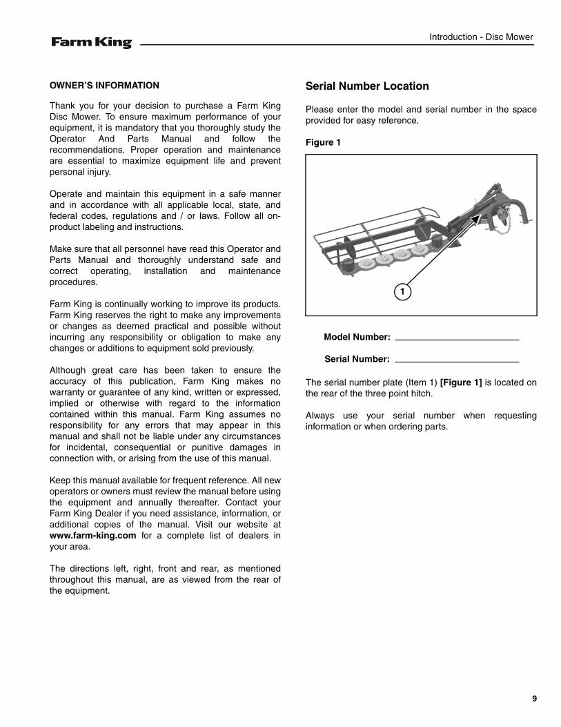
Serial Number Location
Please enter the model and serial number in the spaceprovided for easy reference.
Figure 1
The serial number plate (Item 1) [Figure 1] is located onthe rear of the three point hitch.
Always use your serial number when requestinginformation or when ordering parts.
1
Model Number:
Serial Number:
9
Introduction - Disc Mower
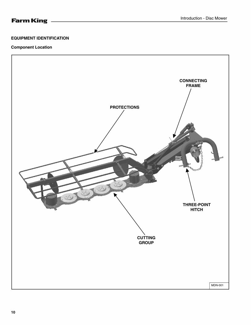
EQUIPMENT IDENTIFICATION
Component Location
MDN-001
THREE-POINT HITCH
CONNECTING FRAME
PROTECTIONS
CUTTING GROUP
10
Safety - Disc Mower
SAFETY
SAFETY INSTRUCTIONS . . . . . . . . . . . . . . . . . . . . . . . . . . . . . . . . . . . . . . . . . . . . . . . . . . . . . . . . 13Safe Operation Is The Operator’s Responsibility . . . . . . . . . . . . . . . . . . . . . . . . . . . . . . . . . . . . 13Safe Operation Needs A Qualified Operator . . . . . . . . . . . . . . . . . . . . . . . . . . . . . . . . . . . . . . . . 13Use Safety Rules . . . . . . . . . . . . . . . . . . . . . . . . . . . . . . . . . . . . . . . . . . . . . . . . . . . . . . . . . . . . 14Transport Safety . . . . . . . . . . . . . . . . . . . . . . . . . . . . . . . . . . . . . . . . . . . . . . . . . . . . . . . . . . . . . 14Machine Requirements And Capabilities . . . . . . . . . . . . . . . . . . . . . . . . . . . . . . . . . . . . . . . . . .15
FIRE PREVENTION . . . . . . . . . . . . . . . . . . . . . . . . . . . . . . . . . . . . . . . . . . . . . . . . . . . . . . . . . . . . . 15Maintenance . . . . . . . . . . . . . . . . . . . . . . . . . . . . . . . . . . . . . . . . . . . . . . . . . . . . . . . . . . . . . . . . 15Operation . . . . . . . . . . . . . . . . . . . . . . . . . . . . . . . . . . . . . . . . . . . . . . . . . . . . . . . . . . . . . . . . . . 15Starting . . . . . . . . . . . . . . . . . . . . . . . . . . . . . . . . . . . . . . . . . . . . . . . . . . . . . . . . . . . . . . . . . . . . 15Electrical . . . . . . . . . . . . . . . . . . . . . . . . . . . . . . . . . . . . . . . . . . . . . . . . . . . . . . . . . . . . . . . . . . . 16Hydraulic System . . . . . . . . . . . . . . . . . . . . . . . . . . . . . . . . . . . . . . . . . . . . . . . . . . . . . . . . . . . . 16Welding And Grinding . . . . . . . . . . . . . . . . . . . . . . . . . . . . . . . . . . . . . . . . . . . . . . . . . . . . . . . . . 16Fire Extinguishers . . . . . . . . . . . . . . . . . . . . . . . . . . . . . . . . . . . . . . . . . . . . . . . . . . . . . . . . . . . .16
SAFETY SIGNS (DECALS) . . . . . . . . . . . . . . . . . . . . . . . . . . . . . . . . . . . . . . . . . . . . . . . . . . . . . . . 17
EQUIPMENT DECALS AND SIGNS . . . . . . . . . . . . . . . . . . . . . . . . . . . . . . . . . . . . . . . . . . . . . . . . 18
SAFETY SIGN-OFF FORM . . . . . . . . . . . . . . . . . . . . . . . . . . . . . . . . . . . . . . . . . . . . . . . . . . . . . . . 20
11

Safety - Disc Mower
12
Safety - Disc Mower
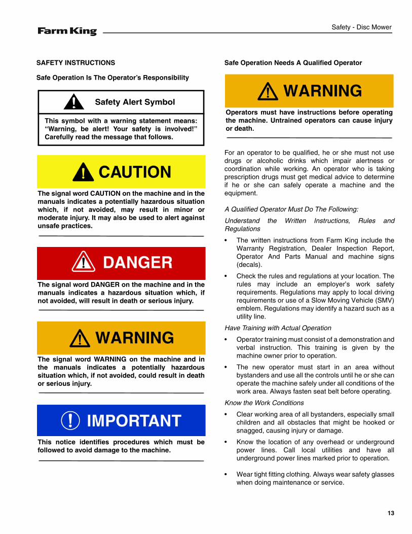
SAFETY INSTRUCTIONS
Safe Operation Is The Operator’s Responsibility
Safe Operation Needs A Qualified Operator
For an operator to be qualified, he or she must not usedrugs or alcoholic drinks which impair alertness orcoordination while working. An operator who is takingprescription drugs must get medical advice to determineif he or she can safely operate a machine and theequipment.
A Qualified Operator Must Do The Following:
Understand the Written Instructions, Rules andRegulations
• The written instructions from Farm King include theWarranty Registration, Dealer Inspection Report,Operator And Parts Manual and machine signs(decals).
• Check the rules and regulations at your location. Therules may include an employer’s work safetyrequirements. Regulations may apply to local drivingrequirements or use of a Slow Moving Vehicle (SMV)emblem. Regulations may identify a hazard such as autility line.
Have Training with Actual Operation
• Operator training must consist of a demonstration andverbal instruction. This training is given by themachine owner prior to operation.
• The new operator must start in an area withoutbystanders and use all the controls until he or she canoperate the machine safely under all conditions of thework area. Always fasten seat belt before operating.
Know the Work Conditions
• Clear working area of all bystanders, especially smallchildren and all obstacles that might be hooked orsnagged, causing injury or damage.
• Know the location of any overhead or undergroundpower lines. Call local utilities and have allunderground power lines marked prior to operation.
• Wear tight fitting clothing. Always wear safety glasseswhen doing maintenance or service.
This symbol with a warning statement means:“Warning, be alert! Your safety is involved!”Carefully read the message that follows.
Safety Alert Symbol
The signal word CAUTION on the machine and in themanuals indicates a potentially hazardous situationwhich, if not avoided, may result in minor ormoderate injury. It may also be used to alert againstunsafe practices.
The signal word DANGER on the machine and in themanuals indicates a hazardous situation which, ifnot avoided, will result in death or serious injury.
The signal word WARNING on the machine and inthe manuals indicates a potentially hazardoussituation which, if not avoided, could result in deathor serious injury.
This notice identifies procedures which must befollowed to avoid damage to the machine.
Operators must have instructions before operatingthe machine. Untrained operators can cause injuryor death.
13
Safety - Disc Mower
SAFETY INSTRUCTIONS (CONT’D)
Use Safety Rules
• Read and follow instructions in this manual and thetractor’s Operators Manual before operating.
• Under no circumstances should young children beallowed to work with this equipment.
• This equipment is dangerous to children and personsunfamiliar with its operation.
• If the elderly are assisting with work, their physicallimitations need to be recognized andaccommodated.
• Stay clear of overhead power lines. Electrocution canoccur without direct contact.
• Check for overhead and / or underground lines beforeoperating equipment (if applicable).
• In addition to the design and configuration ofequipment, hazard control and accident preventionare dependent upon the awareness, concern,prudence and proper training of personnel involved inthe operation, transport, maintenance and storage ofequipment.
• Check that the equipment is securely fastened to thetractor / towing vehicle.
• Make sure all the machine controls are in theNEUTRAL position before starting the machine.
• Operate the equipment only from the operator’sposition.
• Operate the equipment according to the OperatorAnd Parts Manual.
• When learning to operate the equipment, do it at aslow rate in an area clear of bystanders, especiallysmall children.
• DO NOT permit personnel to be in the work areawhen operating the equipment.
• The equipment must be used ONLY on approvedtractors / transport vehicles.
• DO NOT modify the equipment in any way.Unauthorized modification may impair the functionand / or safety and could affect the life of theequipment.
• DO NOT make any adjustments or repairs on theequipment while the machine is running.
• Keep shields and guards in place. Replace ifdamaged.
Transport Safety
• DO NOT exceed 20 mph (32 kph). Reduce speed onrough roads and surfaces.
• Comply with state and local laws governing highwaysafety and movement of machinery on public roads.
• The use of flashing amber lights is acceptable in mostlocalities. However, some localities prohibit their use.Local laws should be checked for all highway lightingand marking requirements.
• Always install transport locks, pins or brackets beforetransporting.
• Always yield to oncoming traffic in all situations andmove to the side of the road so any following trafficmay pass.
• Always enter curves or drive up or down hills at a lowspeed and at a gradual steering angle.
• Never allow riders on either tractor or equipment.
• Keep tractor / towing vehicle in a lower gear at alltimes when traveling down steep grades.
• Maintain proper brake settings at all times (ifequipped).
• Stay away from overhead power lines. Electrocutioncan occur without direct contact.
14
Safety - Disc Mower
Machine Requirements And Capabilities
• Stop the machine and engage the parking brake.Install blocks in front of and behind the rear tires of themachine. Install blocks underneath and support theequipment securely before working under raisedequipment.
• Keep bystanders clear of moving parts and the workarea. Keep children away.
• Use increased caution on slopes and near banks andditches to prevent overturn.
• Make certain that the Slow Moving Vehicle (SMV)emblem is installed so that it is visible and legible.When transporting the equipment, use the flashingwarning lights (if equipped) and follow all localregulations.
• Operate this equipment with a machine equipped withan approved Roll-Over Protective Structure (ROPS).Always wear seat belt when the ROPS is up. Seriousinjury or death could result from falling off themachine.
• Before leaving the operator’s position:
1. Always park on a flat level surface.2. Place all controls in neutral.3. Engage the parking brake.4. Stop engine.5. Wait for all moving parts to stop.
• Carry passengers only in designated seating areas.Never allow riders on the machine or equipment.Falling off can result in serious injury or death.
• Start the equipment only when properly seated in theoperator’s seat. Starting a machine in gear can resultin serious injury or death.
• Operate the machine and equipment from theoperator's position only.
• The parking brake must be engaged before leavingthe operator’s seat. Rollaway can occur because thetransmission may not prevent machine movement.
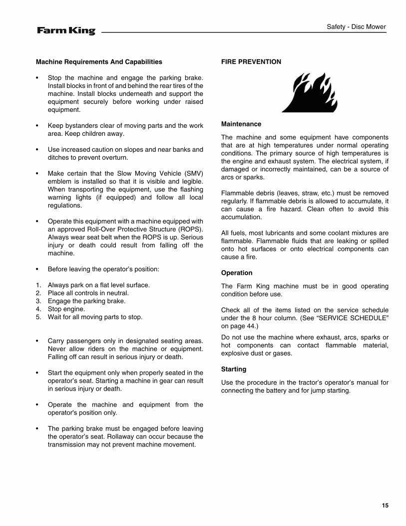
FIRE PREVENTION
Maintenance
The machine and some equipment have componentsthat are at high temperatures under normal operatingconditions. The primary source of high temperatures isthe engine and exhaust system. The electrical system, ifdamaged or incorrectly maintained, can be a source ofarcs or sparks.
Flammable debris (leaves, straw, etc.) must be removedregularly. If flammable debris is allowed to accumulate, itcan cause a fire hazard. Clean often to avoid thisaccumulation.
All fuels, most lubricants and some coolant mixtures areflammable. Flammable fluids that are leaking or spilledonto hot surfaces or onto electrical components cancause a fire.
Operation
The Farm King machine must be in good operatingcondition before use.
Check all of the items listed on the service scheduleunder the 8 hour column. (See “SERVICE SCHEDULE”on page 44.)
Do not use the machine where exhaust, arcs, sparks orhot components can contact flammable material,explosive dust or gases.
Starting
Use the procedure in the tractor’s operator’s manual forconnecting the battery and for jump starting.
15
Safety - Disc Mower
Electrical
Check all electrical wiring and connections for damage.Keep the battery terminals clean and tight. Repair orreplace any damaged part or wires that are loose orfrayed.
Hydraulic System
Check hydraulic tubes, hoses and fittings for damageand leakage. Never use open flame or bare skin to checkfor leaks. Hydraulic tubes and hoses must be properlyrouted and have adequate support and secure clamps.Tighten or replace any parts that show leakage.
Always clean fluid spills. Do not use gasoline or dieselfuel for cleaning parts. Use commercial nonflammablesolvents.
Welding And Grinding
Always clean the machine and equipment, disconnectthe battery, and disconnect the wiring from the machinecontrols before welding. Cover rubber hoses, battery andall other flammable parts. Keep a fire extinguisher nearthe machine when welding.
Have good ventilation when grinding or welding paintedparts. Wear dust mask when grinding painted parts.Toxic dust or gas can be produced.
Dust generated from repairing nonmetallic parts such ashoods, fenders or covers can be flammable or explosive.Repair such components in a well ventilated area awayfrom open flames or sparks.
Fire Extinguishers
Know where fire extinguishers and first aid kits arelocated and how to use them. Inspect the fireextinguisher and service the fire extinguisher regularly.Obey the recommendations on the instructions plate.
16
Safety - Disc Mower
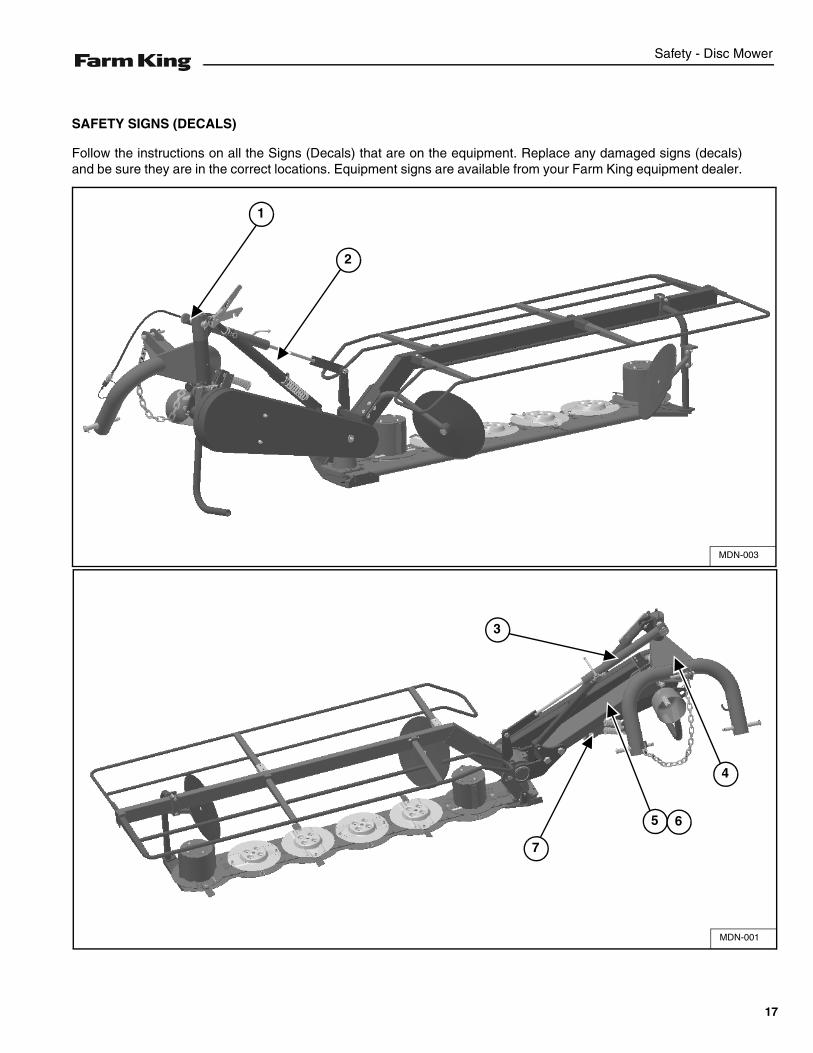
SAFETY SIGNS (DECALS)
Follow the instructions on all the Signs (Decals) that are on the equipment. Replace any damaged signs (decals)and be sure they are in the correct locations. Equipment signs are available from your Farm King equipment dealer.
MDN-001
4
7
5
3
6
MDN-003
1
2
17
Safety - Disc Mower
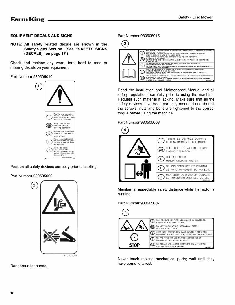
EQUIPMENT DECALS AND SIGNS
NOTE: All safety related decals are shown in theSafety Signs Section. (See “SAFETY SIGNS(DECALS)” on page 17.)
Check and replace any worn, torn, hard to read ormissing decals on your equipment.
Part Number 980505010
Position all safety devices correctly prior to starting.
Part Number 980505009
Dangerous for hands.
Part Number 980505015
Read the instruction and Maintenance Manual and allsafety regulations carefully prior to using the machine.Request such material if lacking. Make sure that all thesafety devices have been correctly mounted and that allthe screws, nuts and bolts are tightened to the correcttorque before using the machine.
Part Number 980505008
Maintain a respectable safety distance while the motor isrunning.
Part Number 980505007
Never touch moving mechanical parts; wait until theyhave come to a rest.
1
2
3
4
5
18
Safety - Disc Mower
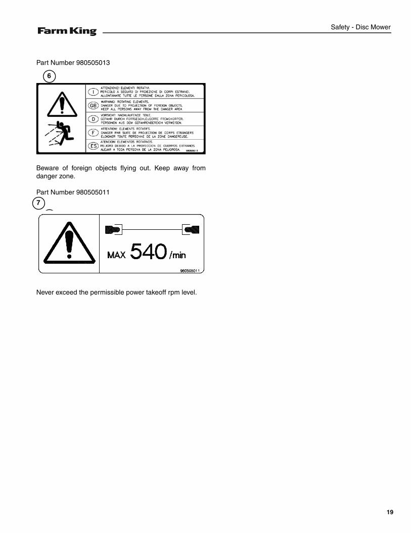
Part Number 980505013
Beware of foreign objects flying out. Keep away fromdanger zone.
Part Number 980505011
Never exceed the permissible power takeoff rpm level.
6
7
7
19
Safety - Disc Mower
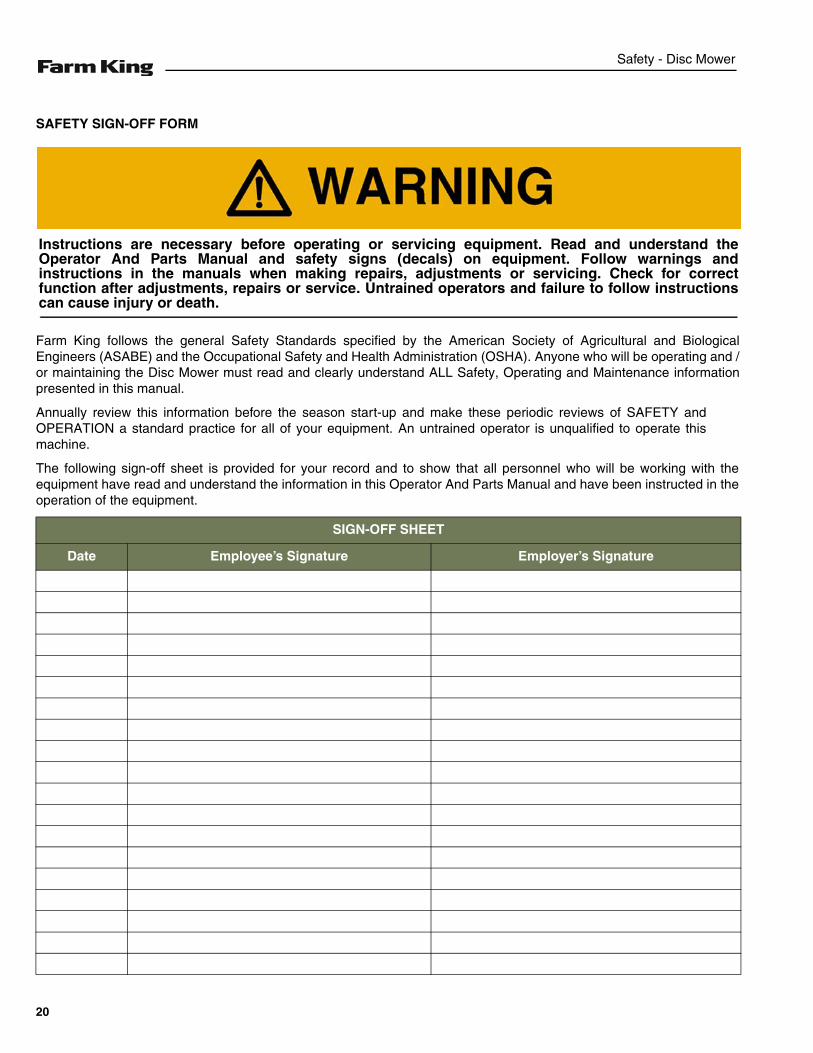
SAFETY SIGN-OFF FORM
Farm King follows the general Safety Standards specified by the American Society of Agricultural and BiologicalEngineers (ASABE) and the Occupational Safety and Health Administration (OSHA). Anyone who will be operating and /or maintaining the Disc Mower must read and clearly understand ALL Safety, Operating and Maintenance informationpresented in this manual.
Annually review this information before the season start-up and make these periodic reviews of SAFETY andOPERATION a standard practice for all of your equipment. An untrained operator is unqualified to operate thismachine.
The following sign-off sheet is provided for your record and to show that all personnel who will be working with theequipment have read and understand the information in this Operator And Parts Manual and have been instructed in theoperation of the equipment.
SIGN-OFF SHEET
Date Employee’s Signature Employer’s Signature
Instructions are necessary before operating or servicing equipment. Read and understand theOperator And Parts Manual and safety signs (decals) on equipment. Follow warnings andinstructions in the manuals when making repairs, adjustments or servicing. Check for correctfunction after adjustments, repairs or service. Untrained operators and failure to follow instructionscan cause injury or death.
20
Operation - Disc Mower
OPERATION
GENERAL INFORMATION . . . . . . . . . . . . . . . . . . . . . . . . . . . . . . . . . . . . . . . . . . . . . . . . . . .23Pre - Operation Checklist . . . . . . . . . . . . . . . . . . . . . . . . . . . . . . . . . . . . . . . . . . . . . . . . . .23Break - In Checklist . . . . . . . . . . . . . . . . . . . . . . . . . . . . . . . . . . . . . . . . . . . . . . . . . . . . . . .24Tractor Requirements . . . . . . . . . . . . . . . . . . . . . . . . . . . . . . . . . . . . . . . . . . . . . . . . . . . . .25Entering And Leaving The Operator’s Position . . . . . . . . . . . . . . . . . . . . . . . . . . . . . . . . . .26
INITIAL SET-UP . . . . . . . . . . . . . . . . . . . . . . . . . . . . . . . . . . . . . . . . . . . . . . . . . . . . . . . . . . . .26Connecting Three-Point Disc Mower To The Tractor . . . . . . . . . . . . . . . . . . . . . . . . . . . . . .26Adjusting Rotating Group Tilt . . . . . . . . . . . . . . . . . . . . . . . . . . . . . . . . . . . . . . . . . . . . . . .27Connecting The PTO Driveline (Three-Point Models) . . . . . . . . . . . . . . . . . . . . . . . . . . . . .28PTO Driveline . . . . . . . . . . . . . . . . . . . . . . . . . . . . . . . . . . . . . . . . . . . . . . . . . . . . . . . . . . .29Connecting Hydraulic Lines . . . . . . . . . . . . . . . . . . . . . . . . . . . . . . . . . . . . . . . . . . . . . . . .32Operating Disc Mower (All Models) . . . . . . . . . . . . . . . . . . . . . . . . . . . . . . . . . . . . . . . . . .33
TRANSPORTING . . . . . . . . . . . . . . . . . . . . . . . . . . . . . . . . . . . . . . . . . . . . . . . . . . . . . . . . . . .38Requirements . . . . . . . . . . . . . . . . . . . . . . . . . . . . . . . . . . . . . . . . . . . . . . . . . . . . . . . . . . .38Transport Position . . . . . . . . . . . . . . . . . . . . . . . . . . . . . . . . . . . . . . . . . . . . . . . . . . . . . . . .39
21

Operation - Disc Mower
22
Operation - Disc Mower
GENERAL INFORMATION
Pre - Operation Checklist
Before operating the Disc Mower for the first time andeach time thereafter, check the following items:
1. Lubricate the equipment per the schedule outline inthe Maintenance Section. (See “SERVICESCHEDULE” on page 44.)
2. Check the Disc Mower hitch for damaged, loose ormissing parts. Repair as needed before operation.
3. Fully clean the equipment.
4. Inspect all safety reflective decals, slow movingvehicle decals and lights where applicable.
5. Check condition of all hydraulic components for leaks.Repair as required.
NOTE: Do not operate with hydraulic leaks.
6. Verify that the safety lock is in the unlock position.
7. Verify that the Disc Mower is properly connected tothe tractor with the safety chain.
MOVING PART HAZARD
To prevent serious injury or death from movingparts:
• Keep hands, feet, hair and clothing away frommoving parts.
• Disconnect and lockout power source beforeadjusting or servicing.
• Do not stand or climb on machine whenoperating.
• Do not approach machine until machine iscompleted stopped and not running.
• Do not remove any protection panels.
AVOID INJURY OR DEATH
Wear safety glasses to prevent eye injury when anyof the following conditions exist:
• When fluids are under pressure.
• Flying debris or loose material is present.
• Engine is running.
• Tools are being used.
AVOID INJURY
Wear hearing protection to prevent hearing losswhen operating.
Leaking fluids under pressure can enter the skinand cause serious injury or death. Immediatemedical attention is required. Wear goggles. Usecardboard to check for leaks.
23
Operation - Disc Mower
Break - In Checklist
Check the following mechanical items after 8 hours ofoperation:
1. Make sure that all hardware are tightened (especiallythose of the cutters).
Check the following mechanical items after 50 hours ofoperation:
1. Change oil in the cutting bar.
2. Change oil in the gearbox.
24
Operation - Disc Mower
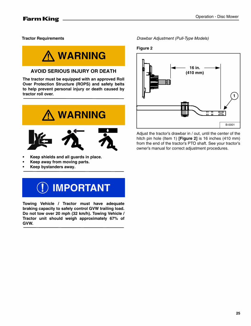
Tractor Requirements Drawbar Adjustment (Pull-Type Models)
Figure 2
Adjust the tractor’s drawbar in / out, until the center of thehitch pin hole (Item 1) [Figure 2] is 16 inches (410 mm)from the end of the tractor’s PTO shaft. See your tractor’sowner’s manual for correct adjustment procedures.
AVOID SERIOUS INJURY OR DEATH
The tractor must be equipped with an approved RollOver Protection Structure (ROPS) and safety beltsto help prevent personal injury or death caused bytractor roll over.
• Keep shields and all guards in place.• Keep away from moving parts.• Keep bystanders away.
Towing Vehicle / Tractor must have adequatebraking capacity to safely control GVW trailing load.Do not tow over 20 mph (32 km/h). Towing Vehicle /Tractor unit should weigh approximately 67% ofGVW.
B-0001
16 in.(410 mm)
1
25
Operation - Disc Mower
Entering And Leaving The Operator’s Position
Entering The Operator’s Position
Move to the operator’s position, start the engine andrelease the parking brake.
Leaving The Operator’s Position
Park the tractor / equipment on a flat level surface.
Place all controls in neutral, engage the park brake, stopthe engine and wait for all moving parts to stop. Leavethe operator’s position.
INITIAL SET-UP
Connecting Three-Point Disc Mower To The Tractor
Always inspect the tractor’s three-point arms and DiscMower hitch before connecting. See the tractor’s owner’smanual.
Enter the operator’s position. (See “Entering TheOperator’s Position” on page 26.)
Move the tractor into position in front of the Disc Mower.
Move the tractor backwards, aligning the three-pointarms with the Disc Mower hitch.
NOTE: The jack may need to be lowered or raised forproper alignment of the drawbar and hitch.
Leave the operator’s position. (See “Leaving TheOperator’s Position” on page 26.)
Follow the instructions in your tractor’s operationmanual for the correct procedure.
AVOID INJURY OR DEATHBefore you leave the operator’s position:• Always park on a flat level surface.• Place all controls in NEUTRAL.• Engage the park brake.• Stop the engine and remove the key.• Wait for all moving parts to stop.
AVOID INJURY OR DEATHBefore moving the tractor, look in all directions andmake sure no bystanders, especially small childrenare in the work area. Do not allow anyone betweenthe tractor and the equipment when backing up tothe equipment for connecting.
26

Operation - Disc Mower
Figure 3
Install the lower lift arms (Item 1) and the lower pins (Item2) on the Disc Mower frame (one side at a time), securein place with safety pins (Item 3) [Figure 3].
Align the upper adjustable arm (Item 4) in the with DiscMower frame, install pin (Item 5) through the Disc Mowerframe and upper adjustable arm. Install safety pin (Item6) [Figure 3].
Figure 4
Remove the retaining pin (Item 1) and slide the jack(Item 2) up, reinstall retaining pin (Item 1) [Figure 4] intothe lower hole on the jack.
Adjusting Rotating Group Tilt
Park the tractor / equipment on a flat level surface.
Place all controls in neutral, engage the park brake, stopthe engine and wait for all moving parts to stop. Leavethe operator’s position. (See “Leaving The Operator’sPosition” on page 26.)
Three-Point Hitch Models
Figure 5
To adjust rotary groups angle, turn the lever (Item 1)[Figure 5] counterclockwise (direction A), moving theDisc Mower frame downwards and reducing the angle.Turn the lever clockwise (direction B), moving the DiscMower frame upwards increasing the angle.
VT-021
1
3
2
4
56
VT-022A
1
2
AVOID INJURY OR DEATHBefore adjusting or servicing the machine:• Always park on a flat level surface.• Place all controls in NEUTRAL.• Engage the park brake.• Stop the engine and remove the key.• Wait for all moving parts to stop.
VT-031
1
A
B
27
Operation - Disc Mower
Connecting The PTO Driveline (Three-Point Models)
NOTE: Clean and grease tractor’s PTO shaft and PTOdriveline coupling each time driveline isconnected.
Stop the engine and leave the operator’s position. (See“Leaving The Operator’s Position” on page 26.)
Remove the PTO driveline from the storage position (ifapplicable).
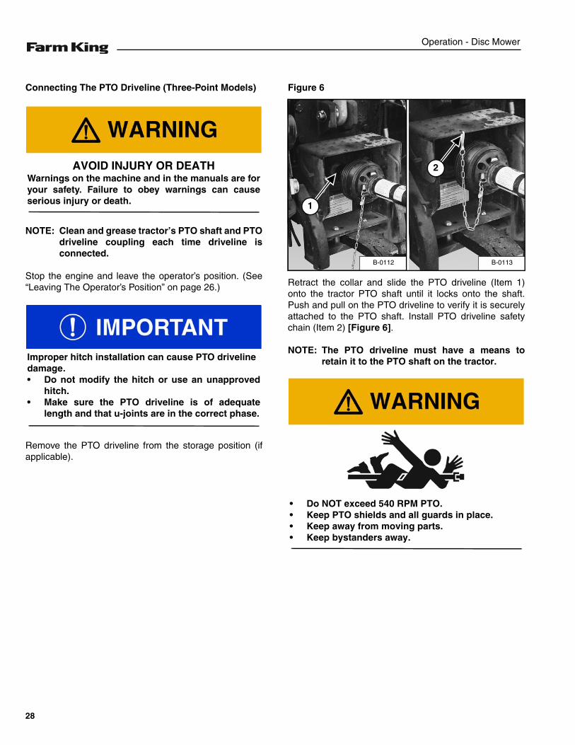
Figure 6
Retract the collar and slide the PTO driveline (Item 1)onto the tractor PTO shaft until it locks onto the shaft.Push and pull on the PTO driveline to verify it is securelyattached to the PTO shaft. Install PTO driveline safetychain (Item 2) [Figure 6].
NOTE: The PTO driveline must have a means toretain it to the PTO shaft on the tractor.
AVOID INJURY OR DEATHWarnings on the machine and in the manuals are foryour safety. Failure to obey warnings can causeserious injury or death.
Improper hitch installation can cause PTO drivelinedamage.• Do not modify the hitch or use an unapproved
hitch.• Make sure the PTO driveline is of adequate
length and that u-joints are in the correct phase.
B-0113B-0112
1
2
• Do NOT exceed 540 RPM PTO.• Keep PTO shields and all guards in place.• Keep away from moving parts.• Keep bystanders away.
28
Operation - Disc Mower
PTO Driveline
PTO Driveline Length Check
NOTE: Due to variations in distances between tractorPTO shafts and implement input shafts,drivelines may need to be shortened or alonger shaft may be required. When fitting theimplement to the tractor, the PTO driveline,with telescoping sections, must be inspected.When the sections are at the mostcompressed operating position, the sectionsmust not “bottom out”. At its shortest length,there must be at least 2 in. (50,8 mm) ofclearance between each section end andopposite section end at the most compressedoperating position. When the sections are atthe most extended position, there must besufficient engagement between the sections.At its farthest operating extension, aminimum section engagement of 33% of shaftlength must be maintained.
PTO Driveline Bottoming Out Check
Stop the engine and leave the operator’s position. (See“Leaving The Operator’s Position” on page 26.)
Make sure the PTO driveline and all rotating componentshave come to a complete stop before leaving theoperator’s position (if applicable).
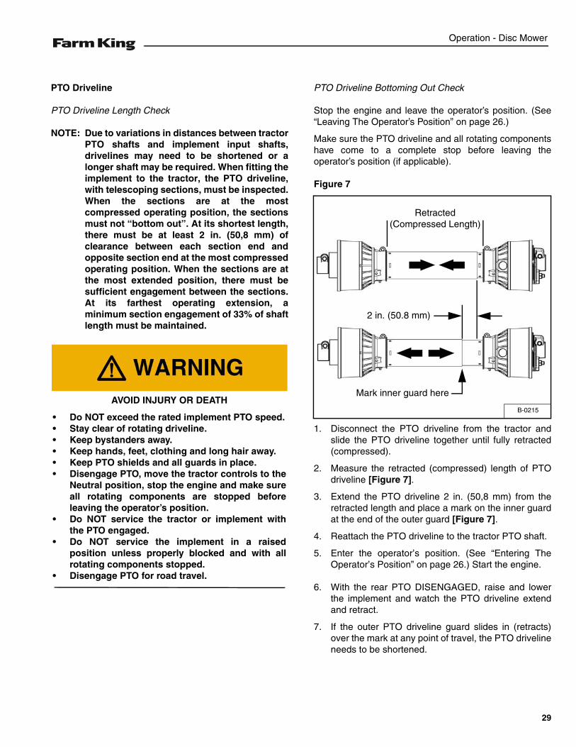
Figure 7
1. Disconnect the PTO driveline from the tractor andslide the PTO driveline together until fully retracted(compressed).
2. Measure the retracted (compressed) length of PTOdriveline [Figure 7].
3. Extend the PTO driveline 2 in. (50,8 mm) from theretracted length and place a mark on the inner guardat the end of the outer guard [Figure 7].
4. Reattach the PTO driveline to the tractor PTO shaft.
5. Enter the operator’s position. (See “Entering TheOperator’s Position” on page 26.) Start the engine.
6. With the rear PTO DISENGAGED, raise and lowerthe implement and watch the PTO driveline extendand retract.
7. If the outer PTO driveline guard slides in (retracts)over the mark at any point of travel, the PTO drivelineneeds to be shortened.
AVOID INJURY OR DEATH
• Do NOT exceed the rated implement PTO speed.• Stay clear of rotating driveline.• Keep bystanders away.• Keep hands, feet, clothing and long hair away.• Keep PTO shields and all guards in place.• Disengage PTO, move the tractor controls to the
Neutral position, stop the engine and make sureall rotating components are stopped beforeleaving the operator’s position.
• Do NOT service the tractor or implement withthe PTO engaged.
• Do NOT service the implement in a raisedposition unless properly blocked and with allrotating components stopped.
• Disengage PTO for road travel.
B-0215
Retracted (Compressed Length)
Mark inner guard here
2 in. (50.8 mm)
29
Operation - Disc Mower
Reducing The PTO Driveline Length
Stop the engine and leave the operator’s position. (See“Leaving The Operator’s Position” on page 26.)
Make sure the PTO driveline and all rotating componentshave come to a complete stop before leaving theoperator’s position.
Remove the PTO driveline from the tractor and place instorage position (if equipped).
Enter the operator’s position. (See “Entering TheOperator’s Position” on page 26.) Start the engine.
Raise or lower the disc to get the shortest distancebetween the tractor PTO shaft and disc gearbox PTOshaft.
Stop the engine and leave the operator’s position. (See“Leaving The Operator’s Position” on page 26.)
Pull the PTO driveline apart and reinstall each individualsection; one half to the tractor PTO shaft and one half tothe implement gearbox PTO shaft.
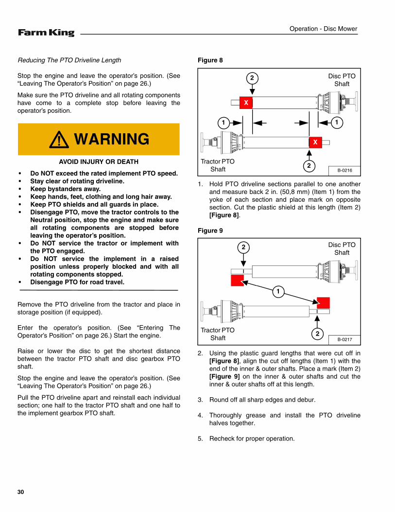
Figure 8
1. Hold PTO driveline sections parallel to one anotherand measure back 2 in. (50,8 mm) (Item 1) from theyoke of each section and place mark on oppositesection. Cut the plastic shield at this length (Item 2)[Figure 8].
Figure 9
2. Using the plastic guard lengths that were cut off in[Figure 8], align the cut off lengths (Item 1) with theend of the inner & outer shafts. Place a mark (Item 2)[Figure 9] on the inner & outer shafts and cut theinner & outer shafts off at this length.
3. Round off all sharp edges and debur.
4. Thoroughly grease and install the PTO drivelinehalves together.
5. Recheck for proper operation.
AVOID INJURY OR DEATH
• Do NOT exceed the rated implement PTO speed.• Stay clear of rotating driveline.• Keep bystanders away.• Keep hands, feet, clothing and long hair away.• Keep PTO shields and all guards in place.• Disengage PTO, move the tractor controls to the
Neutral position, stop the engine and make sureall rotating components are stopped beforeleaving the operator’s position.
• Do NOT service the tractor or implement withthe PTO engaged.
• Do NOT service the implement in a raisedposition unless properly blocked and with allrotating components stopped.
• Disengage PTO for road travel.
B-0216
Tractor PTO Shaft
Disc PTO Shaft
X
1
2
2
X
1
B-0217
Tractor PTO Shaft
Disc PTO Shaft
1
2
2
30
Operation - Disc Mower
PTO Driveline Engagement Check
Stop the engine and leave the operator’s position. (See“Leaving The Operator’s Position” on page 26.)
Make sure the PTO driveline and all rotating componentshave come to a complete stop before exiting the compacttractor.
1. Disconnect the PTO driveline from the tractor andfully slide the driveline sections together (retracted).
Figure 10
2. Measure the retracted (compressed) length of thePTO driveline between the bases of the plastic guards[Figure 10].
3. Multiply the retracted driveline length by 1.667 todetermine the PTO driveline Maximum OperatingLength. (i.e.: 25.5 in. (647,7 mm) x 1.667= 42.5 in.(1079,7 mm) Maximum Operating Length).
4. Attach the PTO driveline to the tractor PTO outputshaft.
5. Enter the operator’s position. (See “Entering TheOperator’s Position” on page 26.)
6. With the PTO driveline attached, position the disc towhere the telescoping PTO driveline is at itsmaximum operating extension.
7. Stop the engine and leave the operator’s position.(See “Leaving The Operator’s Position” on page 26.)Make sure the PTO driveline and all rotatingcomponents have come to a complete stop beforeleaving the operator’s position.
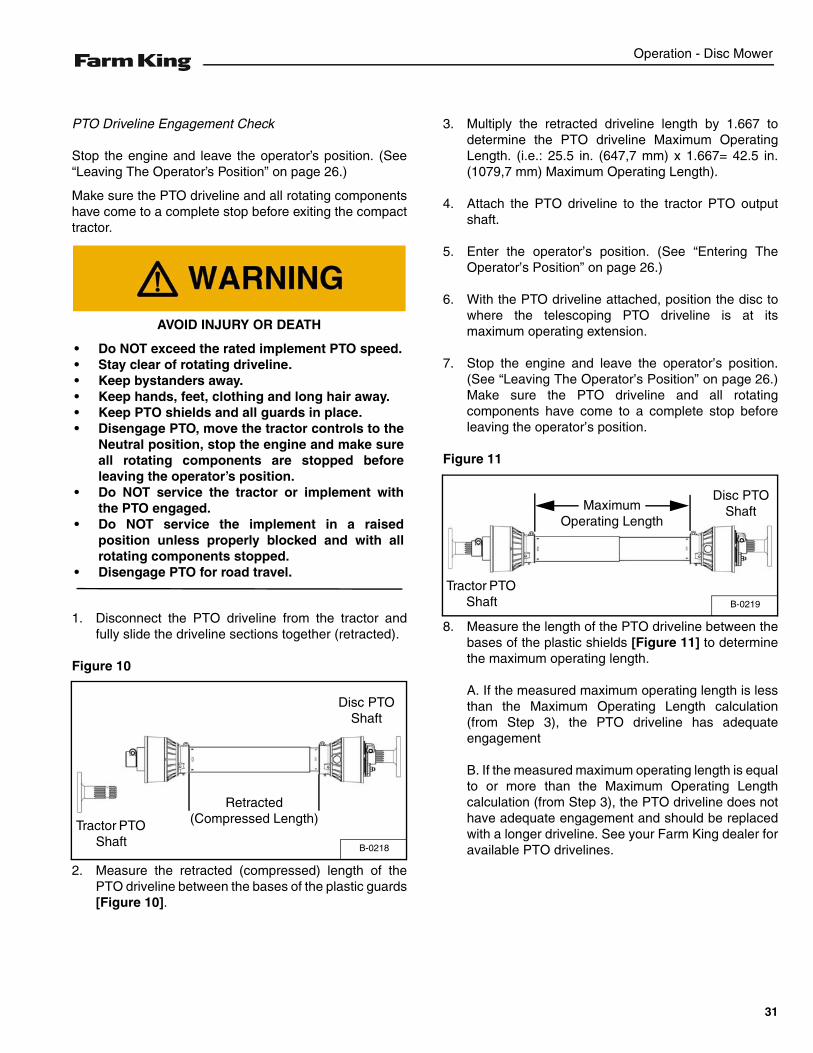
Figure 11
8. Measure the length of the PTO driveline between thebases of the plastic shields [Figure 11] to determinethe maximum operating length.
A. If the measured maximum operating length is lessthan the Maximum Operating Length calculation(from Step 3), the PTO driveline has adequateengagement
B. If the measured maximum operating length is equalto or more than the Maximum Operating Lengthcalculation (from Step 3), the PTO driveline does nothave adequate engagement and should be replacedwith a longer driveline. See your Farm King dealer foravailable PTO drivelines.
AVOID INJURY OR DEATH
• Do NOT exceed the rated implement PTO speed.• Stay clear of rotating driveline.• Keep bystanders away.• Keep hands, feet, clothing and long hair away.• Keep PTO shields and all guards in place.• Disengage PTO, move the tractor controls to the
Neutral position, stop the engine and make sureall rotating components are stopped beforeleaving the operator’s position.
• Do NOT service the tractor or implement withthe PTO engaged.
• Do NOT service the implement in a raisedposition unless properly blocked and with allrotating components stopped.
• Disengage PTO for road travel.
B-0218
Tractor PTO Shaft
Disc PTO Shaft
Retracted (Compressed Length)
B-0219
Maximum Operating Length
Disc PTO Shaft
Tractor PTO Shaft
31
Operation - Disc Mower
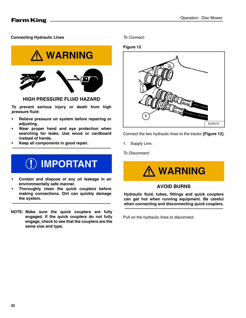
Connecting Hydraulic Lines
NOTE: Make sure the quick couplers are fullyengaged. If the quick couplers do not fullyengage, check to see that the couplers are thesame size and type.
To Connect:
Figure 12
Connect the two hydraulic lines to the tractor [Figure 12].
1. Supply Line.
To Disconnect:
Pull on the hydraulic lines to disconnect.
HIGH PRESSURE FLUID HAZARD
To prevent serious injury or death from highpressure fluid:
• Relieve pressure on system before repairing oradjusting.
• Wear proper hand and eye protection whensearching for leaks. Use wood or cardboardinstead of hands.
• Keep all components in good repair.
• Contain and dispose of any oil leakage in anenvironmentally safe manner.
• Thoroughly clean the quick couplers beforemaking connections. Dirt can quickly damagethe system.
B-0531C
1
AVOID BURNS
Hydraulic fluid, tubes, fittings and quick couplerscan get hot when running equipment. Be carefulwhen connecting and disconnecting quick couplers.
32
Operation - Disc Mower
Operating Disc Mower (All Models)
Move to the operator’s position, start the engine andrelease the parking brake. (See “Entering The Operator’sPosition” on page 26.)
Move the tractor and Disc Mower to work area.
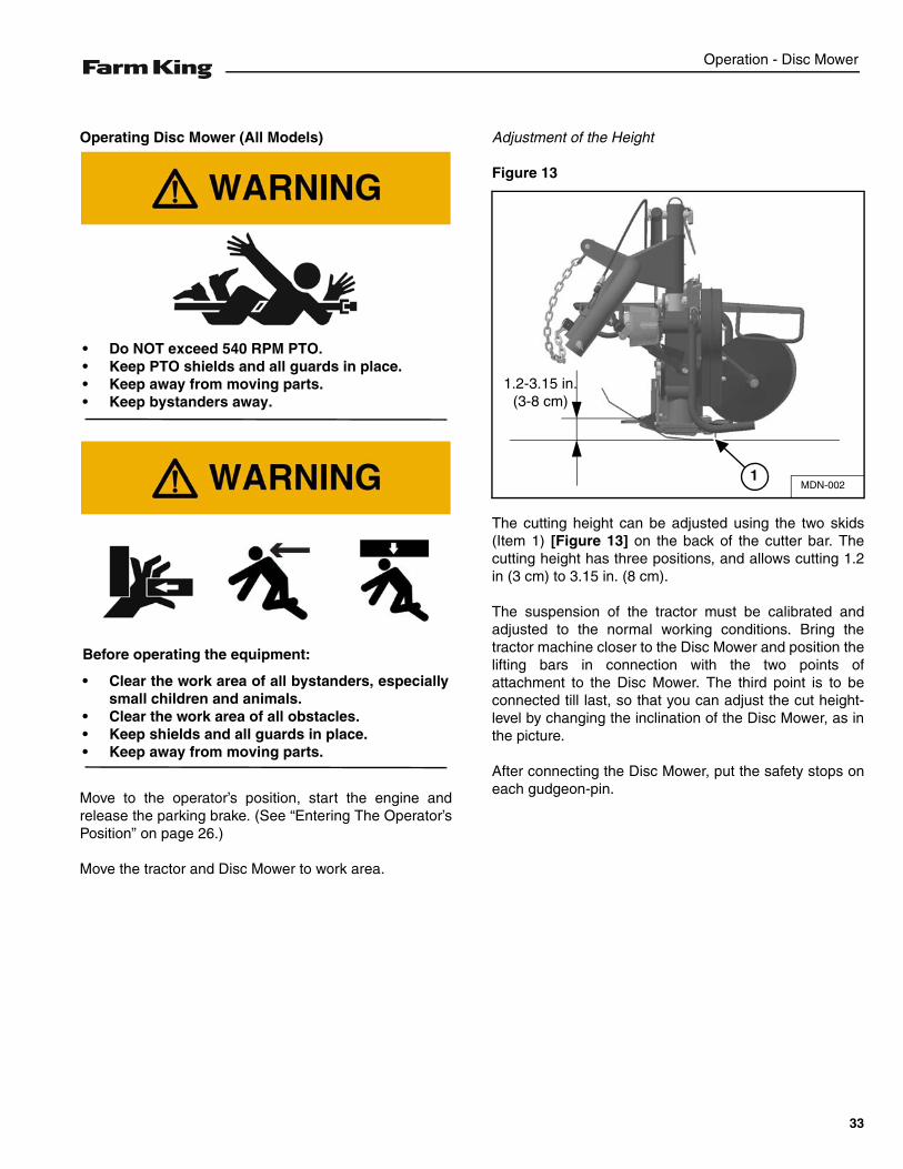
Adjustment of the Height
Figure 13
The cutting height can be adjusted using the two skids(Item 1) [Figure 13] on the back of the cutter bar. Thecutting height has three positions, and allows cutting 1.2in (3 cm) to 3.15 in. (8 cm).
The suspension of the tractor must be calibrated andadjusted to the normal working conditions. Bring thetractor machine closer to the Disc Mower and position thelifting bars in connection with the two points ofattachment to the Disc Mower. The third point is to beconnected till last, so that you can adjust the cut height-level by changing the inclination of the Disc Mower, as inthe picture.
After connecting the Disc Mower, put the safety stops oneach gudgeon-pin.
• Do NOT exceed 540 RPM PTO.• Keep PTO shields and all guards in place.• Keep away from moving parts.• Keep bystanders away.
Before operating the equipment:
• Clear the work area of all bystanders, especiallysmall children and animals.
• Clear the work area of all obstacles.• Keep shields and all guards in place.• Keep away from moving parts.
MDN-002
1.2-3.15 in. (3-8 cm)
1
33
Operation - Disc Mower
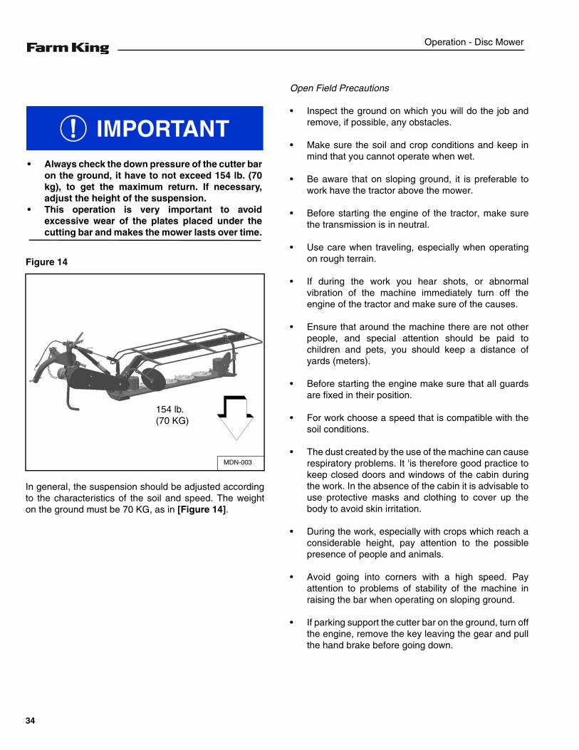
Figure 14
In general, the suspension should be adjusted accordingto the characteristics of the soil and speed. The weighton the ground must be 70 KG, as in [Figure 14].
Open Field Precautions
• Inspect the ground on which you will do the job andremove, if possible, any obstacles.
• Make sure the soil and crop conditions and keep inmind that you cannot operate when wet.
• Be aware that on sloping ground, it is preferable towork have the tractor above the mower.
• Before starting the engine of the tractor, make surethe transmission is in neutral.
• Use care when traveling, especially when operatingon rough terrain.
• If during the work you hear shots, or abnormalvibration of the machine immediately turn off theengine of the tractor and make sure of the causes.
• Ensure that around the machine there are not otherpeople, and special attention should be paid tochildren and pets, you should keep a distance ofyards (meters).
• Before starting the engine make sure that all guardsare fixed in their position.
• For work choose a speed that is compatible with thesoil conditions.
• The dust created by the use of the machine can causerespiratory problems. It 'is therefore good practice tokeep closed doors and windows of the cabin duringthe work. In the absence of the cabin it is advisable touse protective masks and clothing to cover up thebody to avoid skin irritation.
• During the work, especially with crops which reach aconsiderable height, pay attention to the possiblepresence of people and animals.
• Avoid going into corners with a high speed. Payattention to problems of stability of the machine inraising the bar when operating on sloping ground.
• If parking support the cutter bar on the ground, turn offthe engine, remove the key leaving the gear and pullthe hand brake before going down.
• Always check the down pressure of the cutter baron the ground, it have to not exceed 154 lb. (70kg), to get the maximum return. If necessary,adjust the height of the suspension.
• This operation is very important to avoidexcessive wear of the plates placed under thecutting bar and makes the mower lasts over time.
MDN-003
154 lb. (70 KG)
34
Operation - Disc Mower
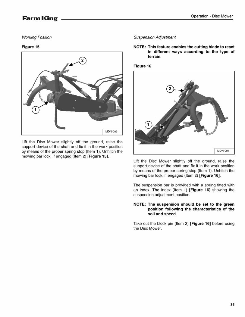
Working Position
Figure 15
Lift the Disc Mower slightly off the ground, raise thesupport device of the shaft and fix it in the work positionby means of the proper spring stop (Item 1). Unhitch themowing bar lock, if engaged (Item 2) [Figure 15].
Suspension Adjustment
NOTE: This feature enables the cutting blade to reactin different ways according to the type ofterrain.
Figure 16
Lift the Disc Mower slightly off the ground, raise thesupport device of the shaft and fix it in the work positionby means of the proper spring stop (Item 1). Unhitch themowing bar lock, if engaged (Item 2) [Figure 16].
The suspension bar is provided with a spring fitted withan index. The index (Item 1) [Figure 16] showing thesuspension adjustment position.
NOTE: The suspension should be set to the greenposition following the characteristics of thesoil and speed.
Take out the block pin (Item 2) [Figure 16] before usingthe Disc Mower.
MDN-003
2
1
MDN-004
2
1
35
Operation - Disc Mower
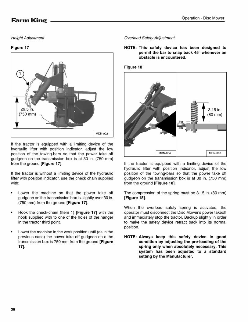
Height Adjustment
Figure 17
If the tractor is equipped with a limiting device of thehydraulic lifter with position indicator, adjust the lowposition of the towing-bars so that the power take offgudgeon on the transmission box is at 30 in. (750 mm)from the ground [Figure 17].
If the tractor is without a limiting device of the hydrauliclifter with position indicator, use the check chain suppliedwith:
• Lower the machine so that the power take offgudgeon on the transmission box is slightly over 30 in.(750 mm) from the ground [Figure 17].
• Hook the check-chain (Item 1) [Figure 17] with thehook supplied with to one of the holes of the hangerin the tractor third point.
• Lower the machine in the work position until (as in theprevious case) the power take off gudgeon on c thetransmission box is 750 mm from the ground [Figure17].
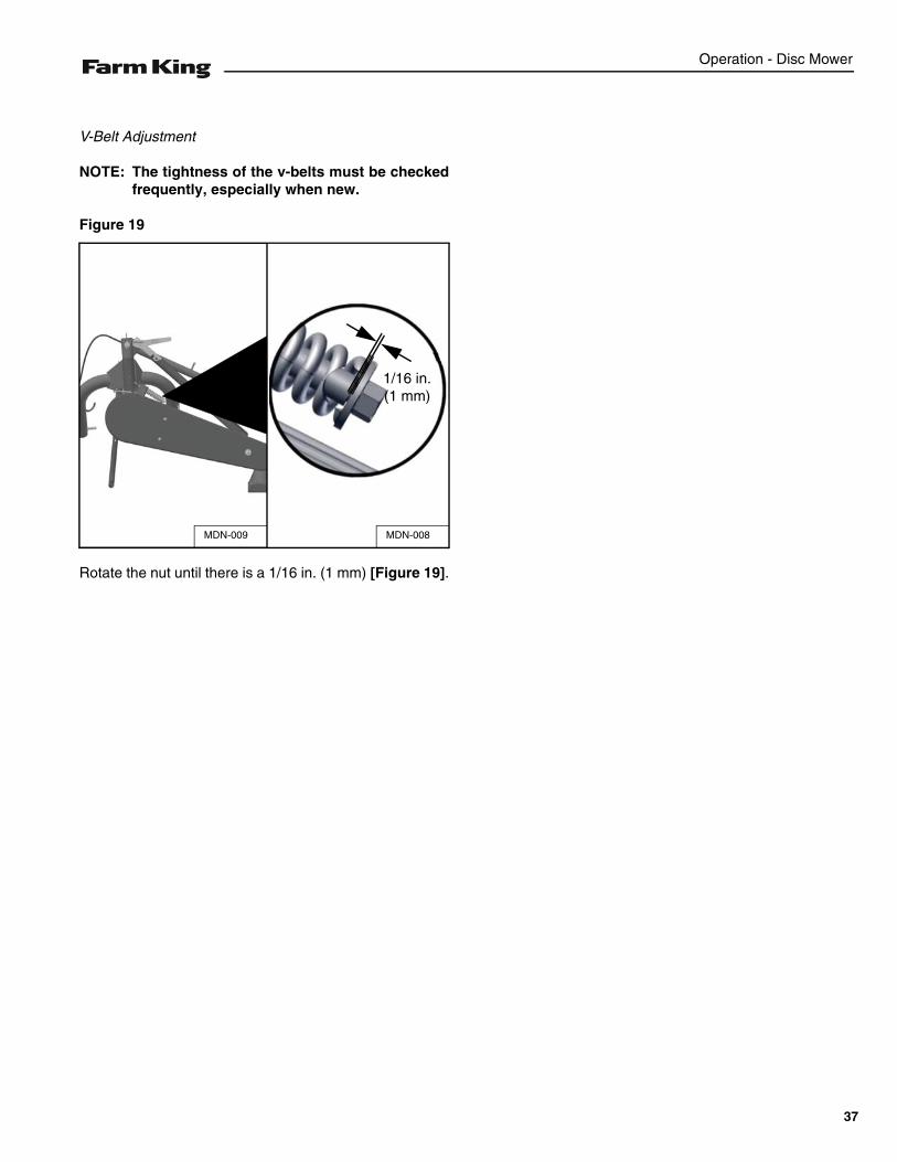
Overload Safety Adjustment
NOTE: This safety device has been designed topermit the bar to snap back 45° whenever anobstacle is encountered.
Figure 18
If the tractor is equipped with a limiting device of thehydraulic lifter with position indicator, adjust the lowposition of the towing-bars so that the power take offgudgeon on the transmission box is at 30 in. (750 mm)from the ground [Figure 18].
The compression of the spring must be 3.15 in. (80 mm)[Figure 18].
When the overload safety spring is activated, theoperator must disconnect the Disc Mower’s power takeoffand immediately stop the tractor. Backup slightly in orderto make the safety device retract back into its normalposition.
NOTE: Always keep this safety device in goodcondition by adjusting the pre-loading of thespring only when absolutely necessary. Thissystem has been adjusted to a standardsetting by the Manufacturer.
MDN-002
29.5 in.(750 mm)
1
MDN-007MDN-004
3.15 in.(80 mm)
36
Operation - Disc Mower
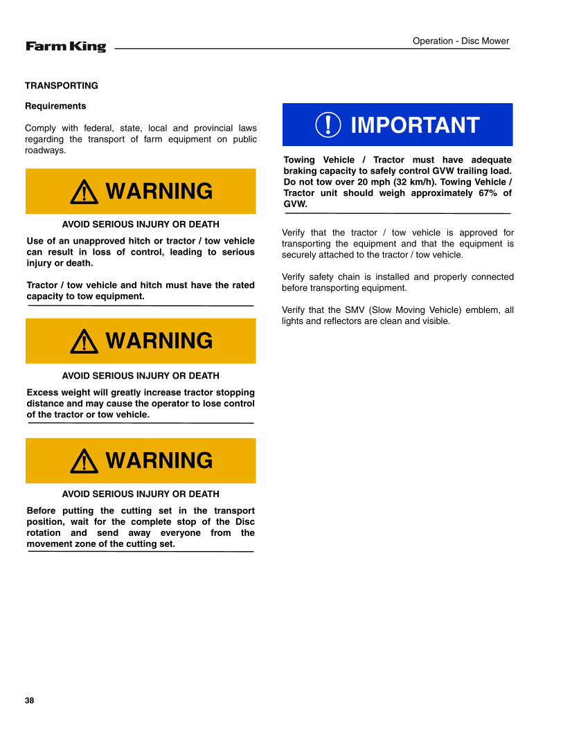
V-Belt Adjustment
NOTE: The tightness of the v-belts must be checkedfrequently, especially when new.
Figure 19
Rotate the nut until there is a 1/16 in. (1 mm) [Figure 19].
MDN-008MDN-009
1/16 in.(1 mm)
37
Operation - Disc Mower
TRANSPORTING
Requirements
Comply with federal, state, local and provincial lawsregarding the transport of farm equipment on publicroadways.
Verify that the tractor / tow vehicle is approved fortransporting the equipment and that the equipment issecurely attached to the tractor / tow vehicle.
Verify safety chain is installed and properly connectedbefore transporting equipment.
Verify that the SMV (Slow Moving Vehicle) emblem, alllights and reflectors are clean and visible.
AVOID SERIOUS INJURY OR DEATH
Use of an unapproved hitch or tractor / tow vehiclecan result in loss of control, leading to seriousinjury or death.
Tractor / tow vehicle and hitch must have the ratedcapacity to tow equipment.
AVOID SERIOUS INJURY OR DEATH
Excess weight will greatly increase tractor stoppingdistance and may cause the operator to lose controlof the tractor or tow vehicle.
AVOID SERIOUS INJURY OR DEATH
Before putting the cutting set in the transportposition, wait for the complete stop of the Discrotation and send away everyone from themovement zone of the cutting set.
Towing Vehicle / Tractor must have adequatebraking capacity to safely control GVW trailing load.Do not tow over 20 mph (32 km/h). Towing Vehicle /Tractor unit should weigh approximately 67% ofGVW.
38
Operation - Disc Mower
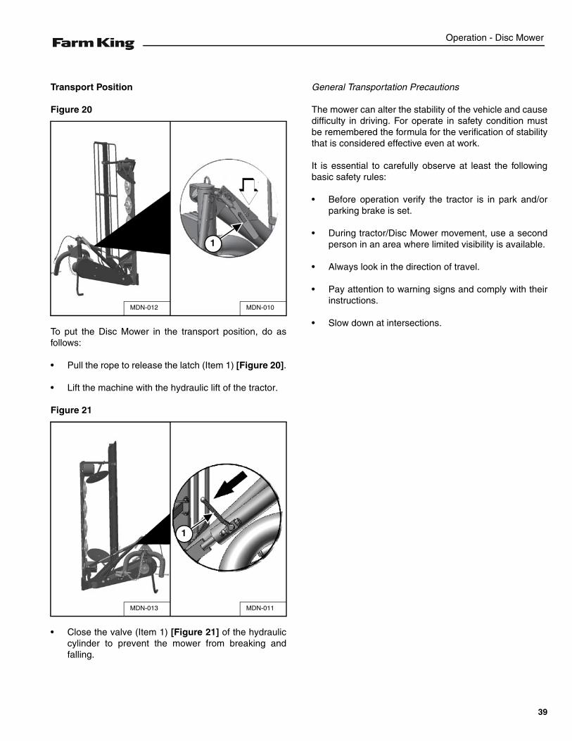
Transport Position
Figure 20
To put the Disc Mower in the transport position, do asfollows:
• Pull the rope to release the latch (Item 1) [Figure 20].
• Lift the machine with the hydraulic lift of the tractor.
Figure 21
• Close the valve (Item 1) [Figure 21] of the hydrauliccylinder to prevent the mower from breaking andfalling.
General Transportation Precautions
The mower can alter the stability of the vehicle and causedifficulty in driving. For operate in safety condition mustbe remembered the formula for the verification of stabilitythat is considered effective even at work.
It is essential to carefully observe at least the followingbasic safety rules:
• Before operation verify the tractor is in park and/orparking brake is set.
• During tractor/Disc Mower movement, use a secondperson in an area where limited visibility is available.
• Always look in the direction of travel.
• Pay attention to warning signs and comply with theirinstructions.
• Slow down at intersections.
MDN-010MDN-012
1
MDN-011MDN-013
1
39

Operation - Disc Mower
40
Maintenance - Disc Mower
MAINTENANCE
TROUBLESHOOTING . . . . . . . . . . . . . . . . . . . . . . . . . . . . . . . . . . . . . . . . . . . . . . . . . . . . . . . . . . . 43Chart . . . . . . . . . . . . . . . . . . . . . . . . . . . . . . . . . . . . . . . . . . . . . . . . . . . . . . . . . . . . . . . . . . . . . . 43
SERVICE SCHEDULE . . . . . . . . . . . . . . . . . . . . . . . . . . . . . . . . . . . . . . . . . . . . . . . . . . . . . . . . . . . 44Maintenance Intervals . . . . . . . . . . . . . . . . . . . . . . . . . . . . . . . . . . . . . . . . . . . . . . . . . . . . . . . . . 44
CLEANING AND MAINTENANCE . . . . . . . . . . . . . . . . . . . . . . . . . . . . . . . . . . . . . . . . . . . . . . . . . . 46General Instructions . . . . . . . . . . . . . . . . . . . . . . . . . . . . . . . . . . . . . . . . . . . . . . . . . . . . . . . . . . 46Precautionary Measures To Be Adopted During The Cleaning And Maintenance Operations . .46Check The Cutting Blades . . . . . . . . . . . . . . . . . . . . . . . . . . . . . . . . . . . . . . . . . . . . . . . . . . . . . 47The Hydraulic System . . . . . . . . . . . . . . . . . . . . . . . . . . . . . . . . . . . . . . . . . . . . . . . . . . . . . . . . . 49Lubrication . . . . . . . . . . . . . . . . . . . . . . . . . . . . . . . . . . . . . . . . . . . . . . . . . . . . . . . . . . . . . . . . . 50
STORAGE AND RETURN TO SERVICE . . . . . . . . . . . . . . . . . . . . . . . . . . . . . . . . . . . . . . . . . . . . . 52Storage . . . . . . . . . . . . . . . . . . . . . . . . . . . . . . . . . . . . . . . . . . . . . . . . . . . . . . . . . . . . . . . . . . . . 52Return To Service . . . . . . . . . . . . . . . . . . . . . . . . . . . . . . . . . . . . . . . . . . . . . . . . . . . . . . . . . . . .52
41

Maintenance - Disc Mower
42
Maintenance - Disc Mower
TROUBLESHOOTING
Chart
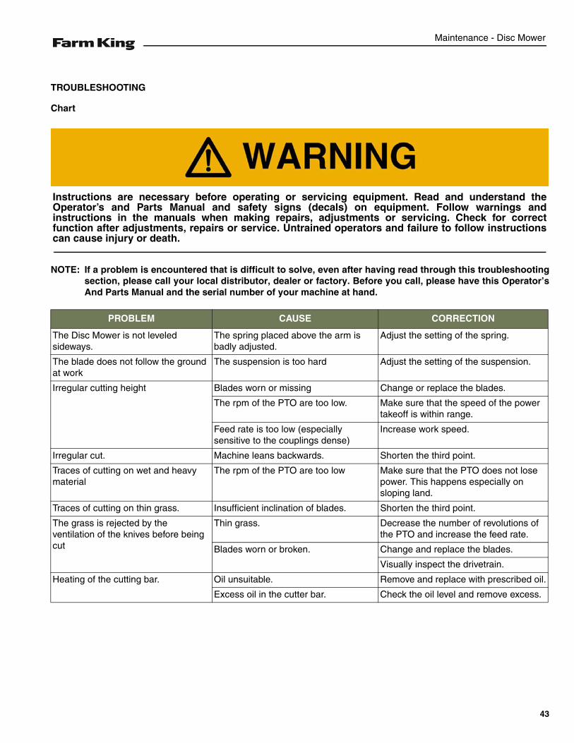
NOTE: If a problem is encountered that is difficult to solve, even after having read through this troubleshootingsection, please call your local distributor, dealer or factory. Before you call, please have this Operator’sAnd Parts Manual and the serial number of your machine at hand.
PROBLEM CAUSE CORRECTION
The Disc Mower is not leveledsideways.
The spring placed above the arm is badly adjusted.
Adjust the setting of the spring.
The blade does not follow the ground at work
The suspension is too hard Adjust the setting of the suspension.
Irregular cutting height Blades worn or missing Change or replace the blades.
The rpm of the PTO are too low. Make sure that the speed of the powertakeoff is within range.
Feed rate is too low (especially sensitive to the couplings dense)
Increase work speed.
Irregular cut. Machine leans backwards. Shorten the third point.
Traces of cutting on wet and heavy material
The rpm of the PTO are too low Make sure that the PTO does not losepower. This happens especially on sloping land.
Traces of cutting on thin grass. Insufficient inclination of blades. Shorten the third point.
The grass is rejected by the ventilation of the knives before being cut
Thin grass. Decrease the number of revolutions of the PTO and increase the feed rate.
Blades worn or broken. Change and replace the blades.
Visually inspect the drivetrain.
Heating of the cutting bar. Oil unsuitable. Remove and replace with prescribed oil.
Excess oil in the cutter bar. Check the oil level and remove excess.
Instructions are necessary before operating or servicing equipment. Read and understand theOperator’s and Parts Manual and safety signs (decals) on equipment. Follow warnings andinstructions in the manuals when making repairs, adjustments or servicing. Check for correctfunction after adjustments, repairs or service. Untrained operators and failure to follow instructionscan cause injury or death.
43
Maintenance - Disc Mower
SERVICE SCHEDULE
Maintenance Intervals
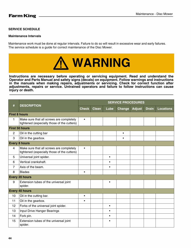
Maintenance work must be done at regular intervals. Failure to do so will result in excessive wear and early failures.The service schedule is a guide for correct maintenance of the Disc Mower.
# DESCRIPTIONSERVICE PROCEDURES
Check Clean Lube Change Adjust Drain Locations
First 8 hours
1 Make sure that all screws are completely tightened (especially those of the cutters)
•
First 50 hours
2 Oil in the cutting bar •
3 Oil in the gearbox. •
Every 8 hours
4 Make sure that all screws are completely tightened (especially those of the cutters)
•
5 Universal joint spider. •
6 Vertical crankshaft. •
7 Axis of the beam. •
8 Blades •
Every 20 hours
9 Extension tubes of the universal joint spider.
•
Every 40 hours
10 Oil in the cutting bar. •
11 Oil in the gearbox. •
12 Forks of the universal joint spider. •
13 Input Drive Hanger Bearings •
14 Fork pin. •
15 Extension tubes of the universal joint spider.
•
Instructions are necessary before operating or servicing equipment. Read and understand theOperator and Parts Manual and safety signs (decals) on equipment. Follow warnings and instructionsin the manuals when making repairs, adjustments or servicing. Check for correct function afteradjustments, repairs or service. Untrained operators and failure to follow instructions can causeinjury or death.
44

Maintenance - Disc Mower
After Each Season
16 Oil in the cutting bar. •
17 Oil in the gearbox. •
# DESCRIPTIONSERVICE PROCEDURES
Check Clean Lube Change Adjust Drain Locations
45

Maintenance - Disc Mower
CLEANING AND MAINTENANCE
General Instructions
The cleaning and maintenance of the machine includescleaning and greasing of the mobile parts etc.
These operations must be carried out following theinstructions of this manual and, when required, usingpersonal protective equipment (gloves, shoes, etc.)
The operations that may be performed at the premisesmay be brought back to the routine maintenanceoperations foreseen by this manual.
The machine, during periods when it is not used, shouldbe parked in a dry and protected area.
After a period of inactivity, perform maintenance. For anytype of maintenance, put the mower on a flat and rigidsurface; if you need to maintain the mower, remove itfrom the tractor.
Precautionary Measures To Be Adopted During The Cleaning And Maintenance Operations
Keep hands, feet, hair and clothing away from movingparts.
Keep the working area free from obstructions, clean anddry.
Always use chains, straps and lifting devices that are ingood condition and of adequate size to lift the DiscMower components. The manual load lifting and handlingmay not be higher than 30 Kg for each operator.
Fluid such as engine oil, hydraulic fluid, coolants, grease,etc. must be disposed of in an environmentally safemanner. Some regulations require that certain spills andleaks on the ground must be cleaned in a specificmanner. See local, state and federal regulations for thecorrect disposal.
Keep shields and guards in place. Replace if damaged.
AVOID INJURY OR DEATHDo not clean, oil or grease by hand and elements ofthe Disc Mower while in motion. It is prohibited toperform any operation on the moving parts repair oradjustment.In case you need to operate with the machine in anelevated position, the locking devices shall beprovided to prevent unintentional lowering.
46
Maintenance - Disc Mower
Check The Cutting Blades
Check the cutting blades systematically before using theDisc Mower.
To get a quality mowing and a use security, check thecutting blades carefully and systematically. Replace thecutting blades in the following cases:
1. Damaged cutting blades.
Because of an uneven ground the cutting blades canhave clefts or deformations, which cause:
- an increase of accident risks,
- a reduction in mowing quality,
- possible failure of the Disc holder.
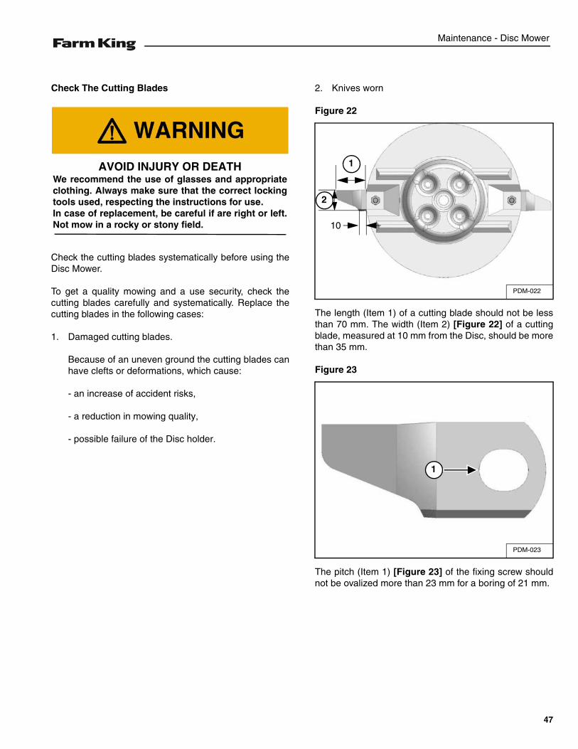
2. Knives worn
Figure 22
The length (Item 1) of a cutting blade should not be lessthan 70 mm. The width (Item 2) [Figure 22] of a cuttingblade, measured at 10 mm from the Disc, should be morethan 35 mm.
Figure 23
The pitch (Item 1) [Figure 23] of the fixing screw shouldnot be ovalized more than 23 mm for a boring of 21 mm.
AVOID INJURY OR DEATHWe recommend the use of glasses and appropriateclothing. Always make sure that the correct lockingtools used, respecting the instructions for use.In case of replacement, be careful if are right or left.Not mow in a rocky or stony field.
PDM-022
1
2
10
PDM-023
1
47
Maintenance - Disc Mower
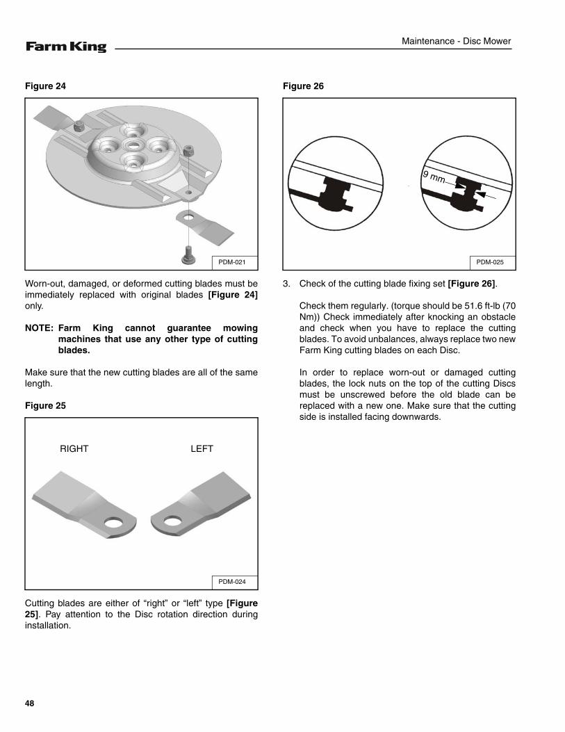
Figure 24
Worn-out, damaged, or deformed cutting blades must beimmediately replaced with original blades [Figure 24]only.
NOTE: Farm King cannot guarantee mowingmachines that use any other type of cuttingblades.
Make sure that the new cutting blades are all of the samelength.
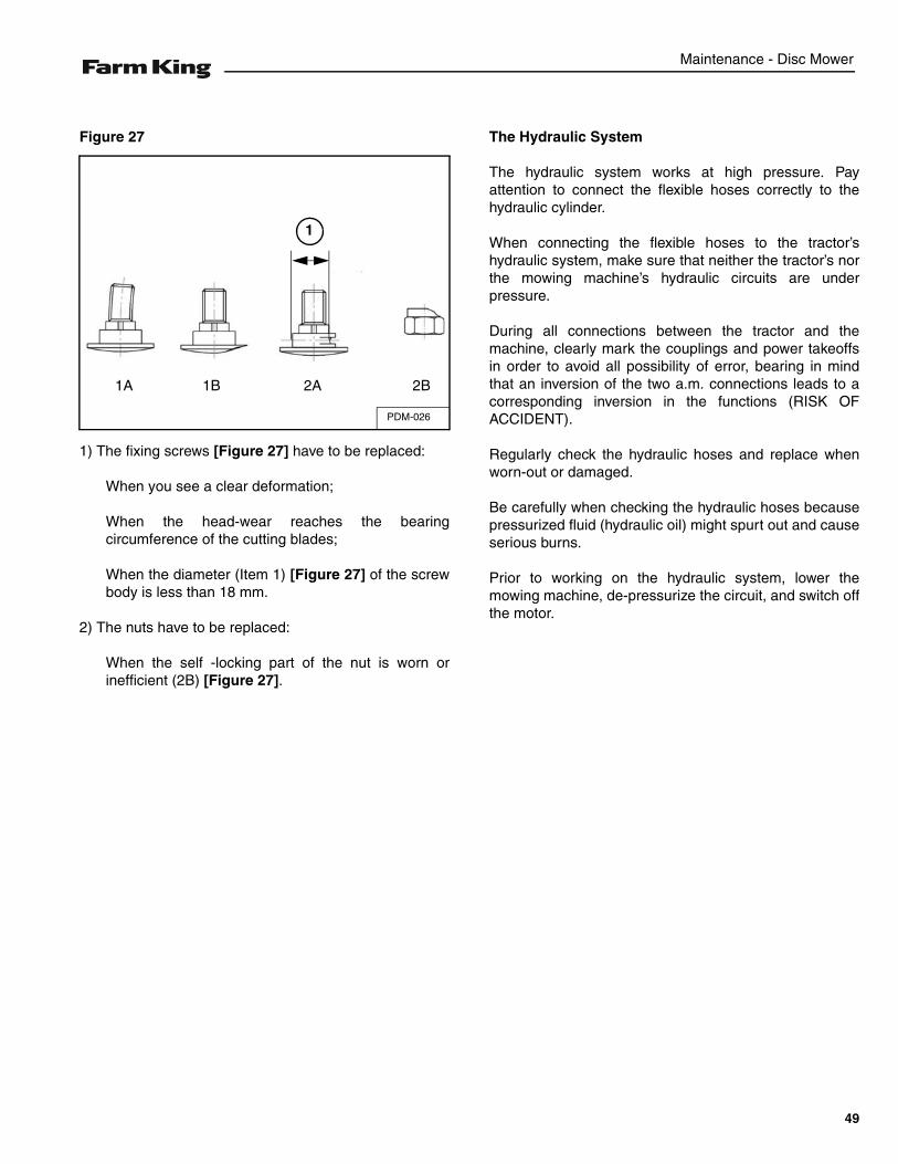
Figure 25
Cutting blades are either of “right” or “left” type [Figure25]. Pay attention to the Disc rotation direction duringinstallation.
Figure 26
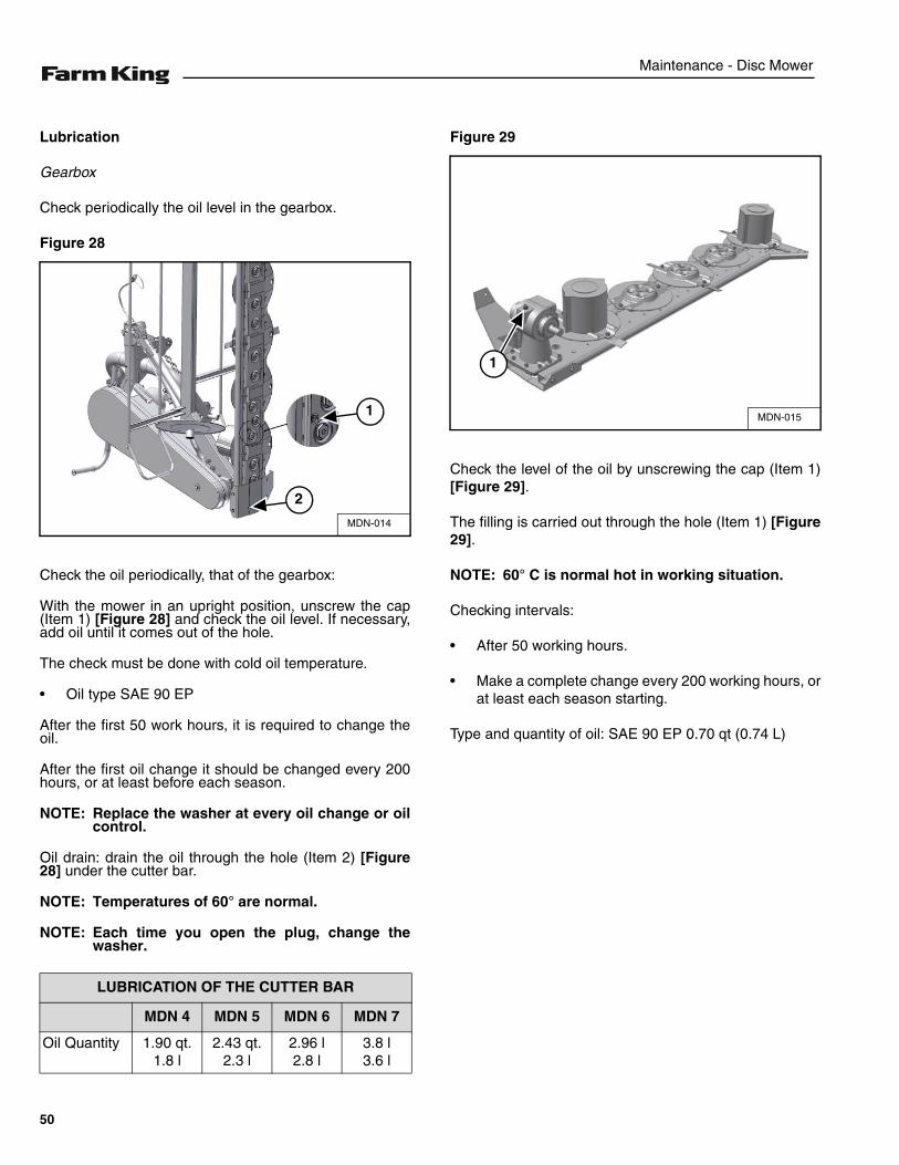
3. Check of the cutting blade fixing set [Figure 26].
Check them regularly. (torque should be 51.6 ft-lb (70Nm)) Check immediately after knocking an obstacleand check when you have to replace the cuttingblades. To avoid unbalances, always replace two newFarm King cutting blades on each Disc.
In order to replace worn-out or damaged cuttingblades, the lock nuts on the top of the cutting Discsmust be unscrewed before the old blade can bereplaced with a new one. Make sure that the cuttingside is installed facing downwards.
PDM-021
PDM-024
RIGHT LEFT
PDM-025
9 mm
48
Maintenance - Disc Mower
Figure 27
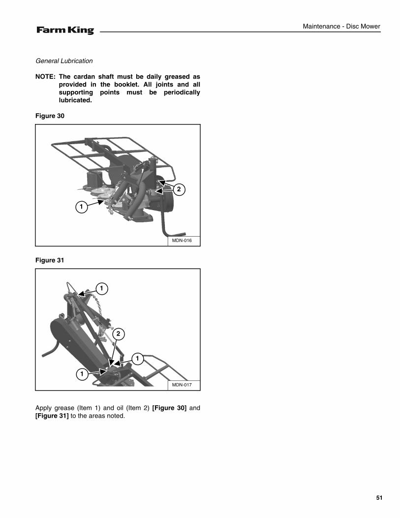
1) The fixing screws [Figure 27] have to be replaced:
When you see a clear deformation;
When the head-wear reaches the bearingcircumference of the cutting blades;
When the diameter (Item 1) [Figure 27] of the screwbody is less than 18 mm.
2) The nuts have to be replaced:
When the self -locking part of the nut is worn orinefficient (2B) [Figure 27].
The Hydraulic System
The hydraulic system works at high pressure. Payattention to connect the flexible hoses correctly to thehydraulic cylinder.
When connecting the flexible hoses to the tractor’shydraulic system, make sure that neither the tractor’s northe mowing machine’s hydraulic circuits are underpressure.
During all connections between the tractor and themachine, clearly mark the couplings and power takeoffsin order to avoid all possibility of error, bearing in mindthat an inversion of the two a.m. connections leads to acorresponding inversion in the functions (RISK OFACCIDENT).
Regularly check the hydraulic hoses and replace whenworn-out or damaged.
Be carefully when checking the hydraulic hoses becausepressurized fluid (hydraulic oil) might spurt out and causeserious burns.
Prior to working on the hydraulic system, lower themowing machine, de-pressurize the circuit, and switch offthe motor.
PDM-026
1A 1B 2A 2B
1
49
Maintenance - Disc Mower
Lubrication
Gearbox
Check periodically the oil level in the gearbox.
Figure 28
Check the oil periodically, that of the gearbox:
With the mower in an upright position, unscrew the cap(Item 1) [Figure 28] and check the oil level. If necessary,add oil until it comes out of the hole.
The check must be done with cold oil temperature.
• Oil type SAE 90 EP
After the first 50 work hours, it is required to change theoil.
After the first oil change it should be changed every 200hours, or at least before each season.
NOTE: Replace the washer at every oil change or oilcontrol.
Oil drain: drain the oil through the hole (Item 2) [Figure28] under the cutter bar.
NOTE: Temperatures of 60° are normal.
NOTE: Each time you open the plug, change thewasher.
Figure 29
Check the level of the oil by unscrewing the cap (Item 1)[Figure 29].
The filling is carried out through the hole (Item 1) [Figure29].
NOTE: 60° C is normal hot in working situation.
Checking intervals:
• After 50 working hours.
• Make a complete change every 200 working hours, orat least each season starting.
Type and quantity of oil: SAE 90 EP 0.70 qt (0.74 L)
LUBRICATION OF THE CUTTER BAR
MDN 4 MDN 5 MDN 6 MDN 7
Oil Quantity 1.90 qt.1.8 l
2.43 qt.2.3 l
2.96 l2.8 l
3.8 l3.6 l
MDN-014
2
1 MDN-015
1
50
Maintenance - Disc Mower
General Lubrication
NOTE: The cardan shaft must be daily greased asprovided in the booklet. All joints and allsupporting points must be periodicallylubricated.
Figure 30
Figure 31
Apply grease (Item 1) and oil (Item 2) [Figure 30] and[Figure 31] to the areas noted.
MDN-016
2
1
MDN-017
1
2
1
1
51
Maintenance - Disc Mower
STORAGE AND RETURN TO SERVICE
Storage
Sometimes it may be necessary to store your Farm KingDisc Mower for an extended period of time. Below is a listof items to perform before storage.
• Thoroughly clean the equipment.
• Lubricate the equipment.
• Inspect the hitch and all welds on the equipment forwear and damage.
• Check for loose hardware, missing guards, ordamaged parts.
• Check for damaged or missing safety signs (decals).Replace if necessary.
• Replace worn or damaged parts.
• Touch up all paint nicks and scratches to preventrusting.
• Store the Disc Mower in a clean, dry, sheltered area.
• Place the equipment flat on the ground.
Return To Service
After the Farm King Disc Mower has been in storage, it isnecessary to follow a list of items to return the equipmentto service.
• Be sure all shields and guards are in place.
• Lubricate the equipment.
• Clean and inspect pusher chain for excessive wear orstiffness. Check for proper adjustment and alignment.
• Inspect and repack wheel bearings with a SAE multipurpose type grease.
• Check that tires are properly inflated.
• Connect to a tractor and operate equipment, verify allfunctions operate correctly.
• Check for leaks. Repair as needed.
• Review the Operator’s Manual.
DO NOT permit children to play on or around thestored machine.
52
Parts Identification - Disc Mower
PARTS IDENTIFICATION
GENERAL INFORMATION . . . . . . . . . . . . . . . . . . . . . . . . . . . . . . . . . . . . . . . . . . . . . . . . . . . . . . . 55
THREE POINT HITCH . . . . . . . . . . . . . . . . . . . . . . . . . . . . . . . . . . . . . . . . . . . . . . . . . . . . . . . . . . . 56
CUTTING GROUP . . . . . . . . . . . . . . . . . . . . . . . . . . . . . . . . . . . . . . . . . . . . . . . . . . . . . . . . . . . . . . 60
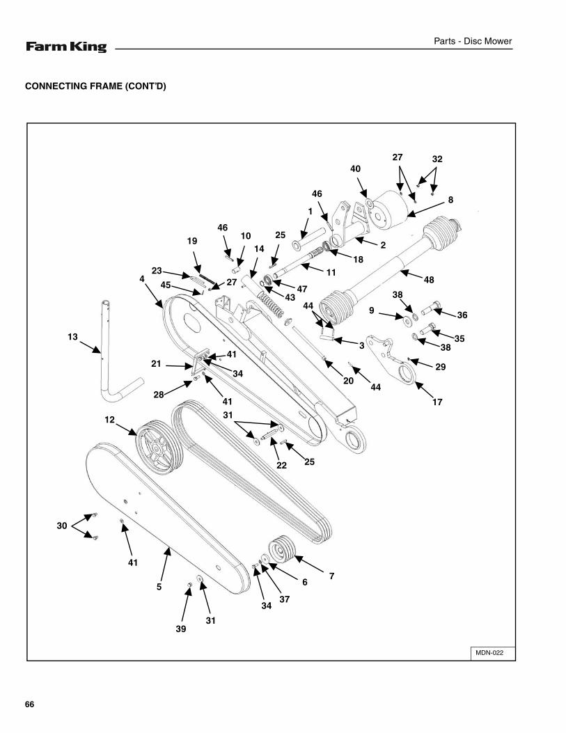
CONNECTING FRAME . . . . . . . . . . . . . . . . . . . . . . . . . . . . . . . . . . . . . . . . . . . . . . . . . . . . . . . . . . 64
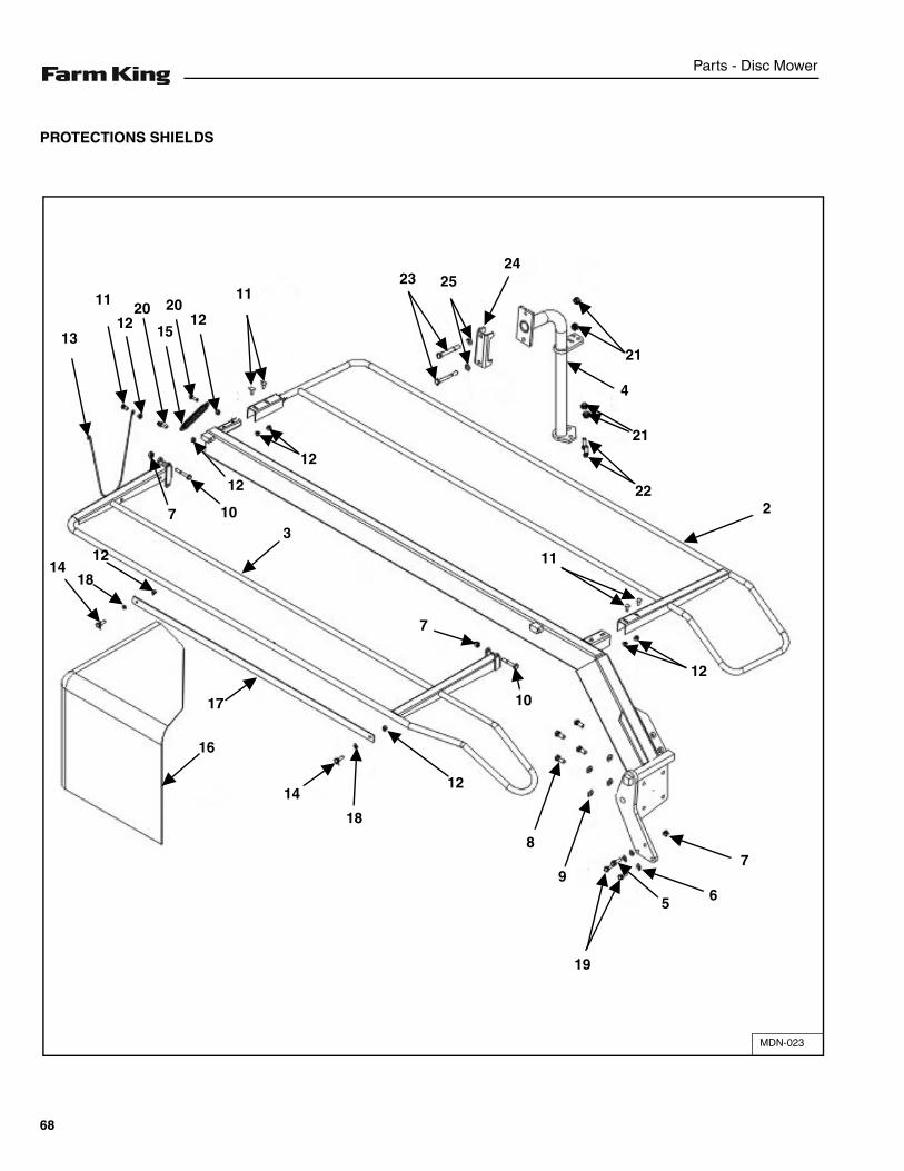
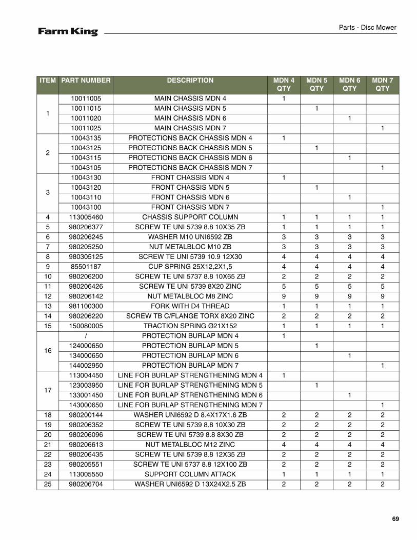
PROTECTIONS SHIELDS . . . . . . . . . . . . . . . . . . . . . . . . . . . . . . . . . . . . . . . . . . . . . . . . . . . . . . . . 68
GRASS-BUFFER DISC . . . . . . . . . . . . . . . . . . . . . . . . . . . . . . . . . . . . . . . . . . . . . . . . . . . . . . . . . . 70
CARDAN SHAFT . . . . . . . . . . . . . . . . . . . . . . . . . . . . . . . . . . . . . . . . . . . . . . . . . . . . . . . . . . . . . . . 72
FREE WHEEL . . . . . . . . . . . . . . . . . . . . . . . . . . . . . . . . . . . . . . . . . . . . . . . . . . . . . . . . . . . . . . . . . 74
GEARBOX . . . . . . . . . . . . . . . . . . . . . . . . . . . . . . . . . . . . . . . . . . . . . . . . . . . . . . . . . . . . . . . . . . . . 76
53

Parts Identification - Disc Mower
54
Parts - Disc Mower
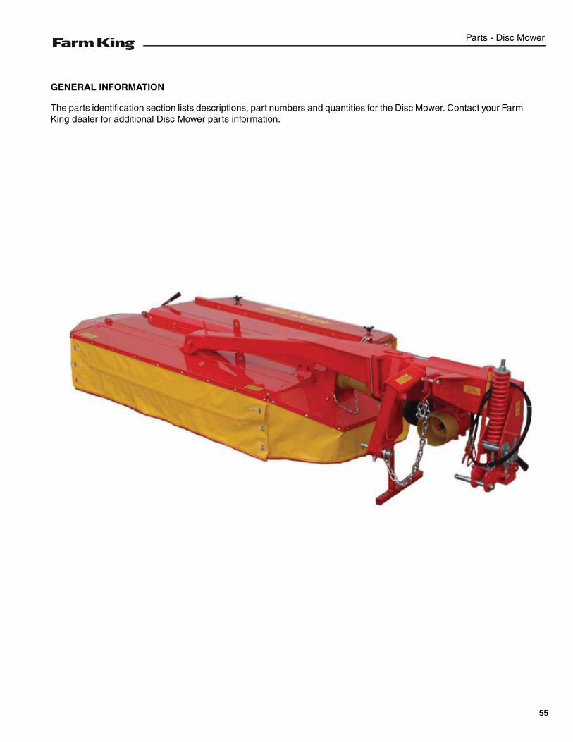
GENERAL INFORMATION
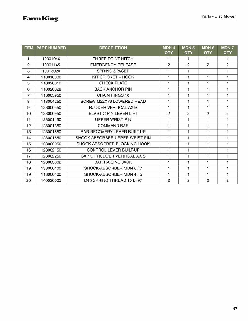
The parts identification section lists descriptions, part numbers and quantities for the Disc Mower. Contact your FarmKing dealer for additional Disc Mower parts information.
55
Parts - Disc Mower
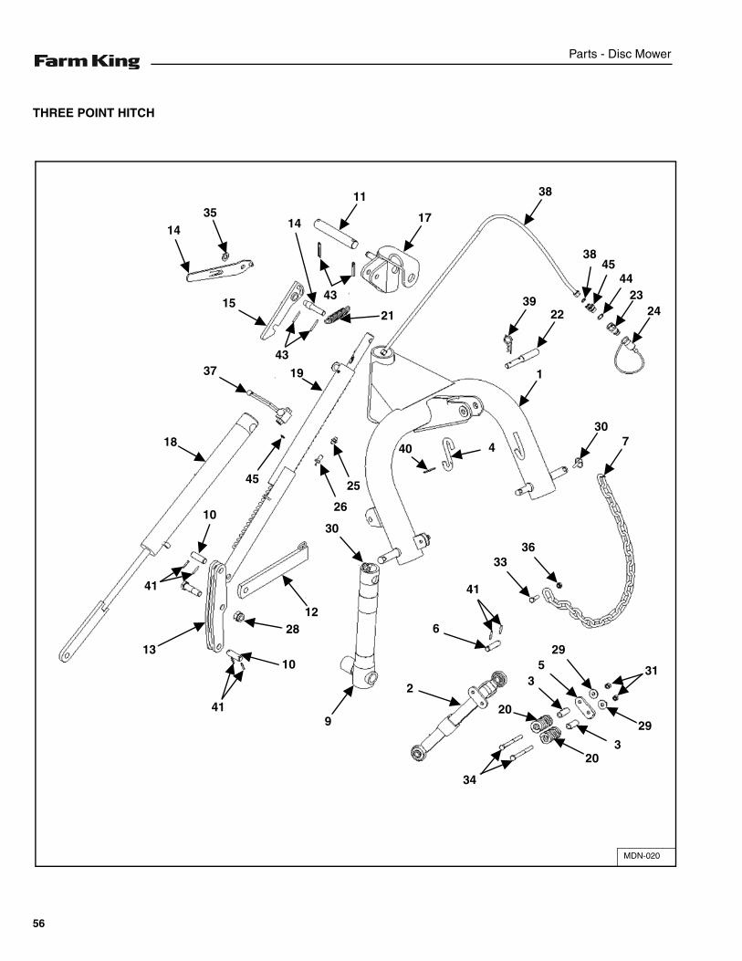
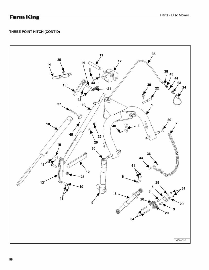
THREE POINT HITCH
MDN-020
1435
11
17
38
3845
4423
242239
1
307440
25
26
30
3336
43
21
43
19
15
37
18
45
10
41
13
41
10
2812
9
2
6
41
34
20
35
29
31
29
320
14
56
Parts - Disc Mower
ITEM PART NUMBER DESCRIPTION MDN 4 QTY
MDN 5 QTY
MDN 6 QTY
MDN 7 QTY
1 10001046 THREE POINT HITCH 1 1 1 1
2 10001145 EMERGENCY RELEASE 2 2 2 2
3 10013020 SPRING SPACER 1 1 1 1
4 110010030 KIT CRICKET + HOOK 1 1 1 1
5 110020010 CHECK PLATE 1 1 1 1
6 110020028 BACK ANCHOR PIN 1 1 1 1
7 113003950 CHAIN RINGS 10 1 1 1 1
8 113004250 SCREW M22X76 LOWERED HEAD 1 1 1 1
9 123000550 RUDDER VERTICAL AXIS 1 1 1 1
10 123000950 ELASTIC PIN LEVER LIFT 2 2 2 2
11 123001150 UPPER WRIST PIN 1 1 1 1
12 123001350 COMMAND BAR 1 1 1 1
13 123001550 BAR RECOVERY LEVER BUILT-UP 1 1 1 1
14 123001850 SHOCK ABSORBER UPPER WRIST PIN 1 1 1 1
15 123002050 SHOCK ABSORBER BLOCKING HOOK 1 1 1 1
16 123002150 CONTROL LEVER BUILT-UP 1 1 1 1
17 123002250 CAP OF RUDDER VERTICAL AXIS 1 1 1 1
18 123003602 BAR RAISING JACK 1 1 1 1
19 133000100 SHOCK-ABSORBER MDN 6 / 7 1 1 1 1
19 113000400 SHOCK-ABSORBER MDN 4 / 5 1 1 1 1
20 140020005 D45 SPRING THREAD 10 L=97 2 2 2 2
57
Parts - Disc Mower
THREE POINT HITCH (CONT’D)
MDN-020
1435
11
17
38
3845
4423
242239
1
307440
25
26
30
3336
43
21
43
19
15
37
18
45
10
41
13
41
10
2812
9
2
6
41
34
20
35
29
31
29
320
14
58
Parts - Disc Mower
ITEM PART NUMBER DESCRIPTION MDN 4 QTY
MDN 5 QTY
MDN 6 QTY
MDN 7 QTY
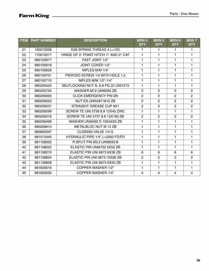
21 160072008 D28 SPRING THREAD 4 L=125 1 1 1 1
22 170010017 HINGE OF 3° POINT HITCH 1^ AND 2^ CAT 1 1 1 1
23 980100617 FAST JOINT 1/2" 1 1 1 1
24 980100618 JOINT COVER 1/2" 1 1 1 1
25 980100626 NIPLES M/M 1/4" 1 1 1 1
26 980100701 PIERCED SCREW 1/4 WITH HOLE 1,5 1 1 1 1
27 980100710 NIPLES M/M 1/2"-1/4" 1 1 1 1
28 980205425 SELFLOCKING NUT N. 6.8 PG 22 UNI7473 1 1 1 1
29 980205724 WASHER M12 UNI6593 ZB 2 2 2 2
30 980206005 CLICK EMERGENCY PIN Ø9 2 2 2 2
31 980206023 NUT ES UNI5587 M12 ZB 2 2 2 2
32 980206031 STRAIGHT GREASE CUP 8X1 2 2 2 2
33 980206099 SCREW TE UNI 5739 8.8 12X45 ZINC 1 1 1 1
34 980206216 SCREW TE UNI 5737 8.8 12X160 ZB 2 2 2 2
35 980206499 WASHER UNI6592 D 19X34X3 ZB 1 1 1 1
36 980206613 METALBLOC NUT M 12 ZB 1 1 1 1
37 980600397 CLOSING VALVE 1/4 G 1 1 1 1
38 981013440 HYDRAULIC PIPE 1/4" L=2000 FD/FD 1 1 1 1
39 981106002 R SPLIT PIN Ø3.5 UNI8833-B 1 1 1 1
40 981108022 ELASTIC PIN UNI8752 5X50 ZB 1 1 1 1
41 981108210 ELASTIC PIN UNI 6873 6X36 ZB 6 6 6 6
42 981108604 ELASTIC PIN UNI 6873 10X60 ZB 2 2 2 2
43 981108608 ELASTIC PIN UNI 6873 6X50 ZB 1 1 1 1
44 981600619 COPPER WASHER 1/2" 1 1 1 1
45 981600630 COPPER WASHER 1/4" 4 4 4 4
59
Parts - Disc Mower
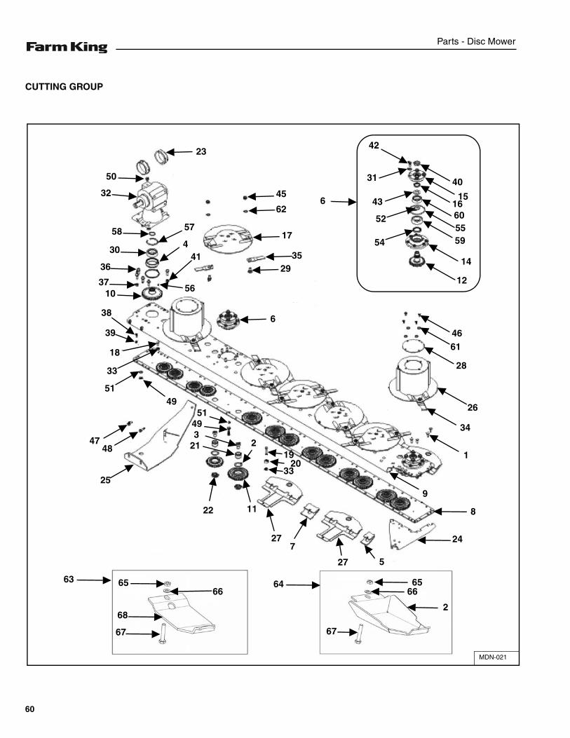
CUTTING GROUP
MDN-021
6
42
31
43
52
12
14
54 59556016
15
40
4661
28
26
34
1
8
24
6566
2
67
64
527
727
1122
21349
51
219
2033
25
4847
4951
33
18
39
386
2935
17
62
45
23
50
32
58
30
36
3710 56
414
57
63 65
68
67
66
9
60
Parts - Disc Mower
ITEM PART NUMBER DESCRIPTION MDN 4 QTY
MDN 5 QTY
MDN 6 QTY
MDN 7 QTY
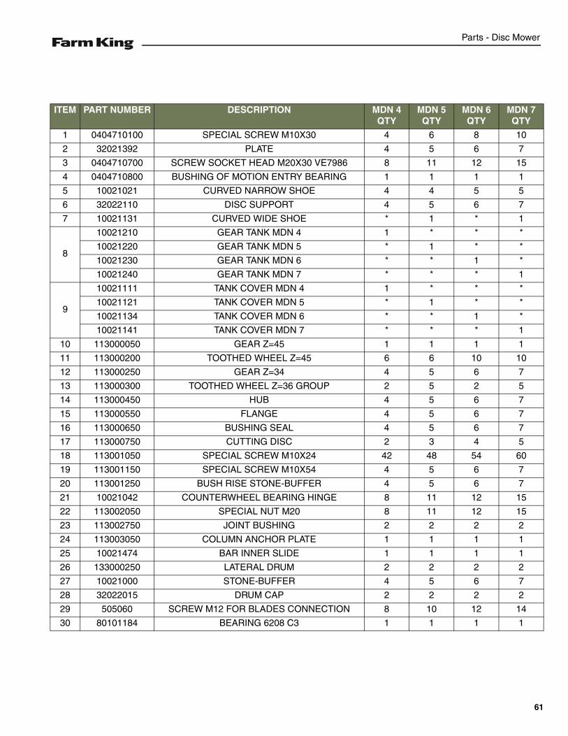
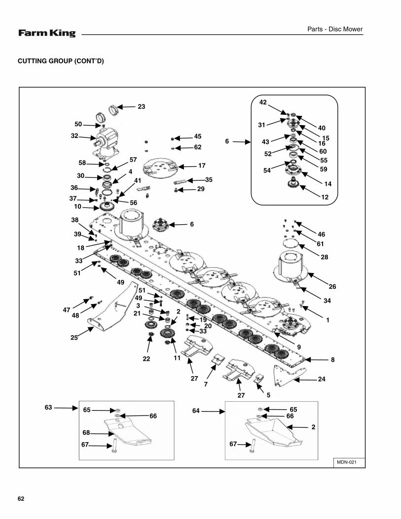
1 0404710100 SPECIAL SCREW M10X30 4 6 8 10
2 32021392 PLATE 4 5 6 7
3 0404710700 SCREW SOCKET HEAD M20X30 VE7986 8 11 12 15
4 0404710800 BUSHING OF MOTION ENTRY BEARING 1 1 1 1
5 10021021 CURVED NARROW SHOE 4 4 5 5
6 32022110 DISC SUPPORT 4 5 6 7
7 10021131 CURVED WIDE SHOE * 1 * 1
8
10021210 GEAR TANK MDN 4 1 * * *
10021220 GEAR TANK MDN 5 * 1 * *
10021230 GEAR TANK MDN 6 * * 1 *
10021240 GEAR TANK MDN 7 * * * 1
9
10021111 TANK COVER MDN 4 1 * * *
10021121 TANK COVER MDN 5 * 1 * *
10021134 TANK COVER MDN 6 * * 1 *
10021141 TANK COVER MDN 7 * * * 1
10 113000050 GEAR Z=45 1 1 1 1
11 113000200 TOOTHED WHEEL Z=45 6 6 10 10
12 113000250 GEAR Z=34 4 5 6 7
13 113000300 TOOTHED WHEEL Z=36 GROUP 2 5 2 5
14 113000450 HUB 4 5 6 7
15 113000550 FLANGE 4 5 6 7
16 113000650 BUSHING SEAL 4 5 6 7
17 113000750 CUTTING DISC 2 3 4 5
18 113001050 SPECIAL SCREW M10X24 42 48 54 60
19 113001150 SPECIAL SCREW M10X54 4 5 6 7
20 113001250 BUSH RISE STONE-BUFFER 4 5 6 7
21 10021042 COUNTERWHEEL BEARING HINGE 8 11 12 15
22 113002050 SPECIAL NUT M20 8 11 12 15
23 113002750 JOINT BUSHING 2 2 2 2
24 113003050 COLUMN ANCHOR PLATE 1 1 1 1
25 10021474 BAR INNER SLIDE 1 1 1 1
26 133000250 LATERAL DRUM 2 2 2 2
27 10021000 STONE-BUFFER 4 5 6 7
28 32022015 DRUM CAP 2 2 2 2
29 505060 SCREW M12 FOR BLADES CONNECTION 8 10 12 14
30 80101184 BEARING 6208 C3 1 1 1 1
61
Parts - Disc Mower
CUTTING GROUP (CONT’D)
MDN-021
6
42
31
43
52
12
14
54 59556016
15
40
4661
28
26
34
1
8
24
6566
2
67
64
527
727
1122
21349
51
219
2033
25
4847
4951
33
18
39
386
2935
17
62
45
23
50
32
58
30
36
3710 56
414
57
63 65
68
67
66
9
62

Parts - Disc Mower
ITEM PART NUMBER DESCRIPTION MDN 4 QTY
MDN 5 QTY
MDN 6 QTY
MDN 7 QTY
31 85501187 CUP SPRING 25X12,2X1,5 16 20 24 28
32 914200500 TRANSMISSION BOX LF-142A 1 1 1 1
33 980200018 NUT ES M10 UNI5587 94 100 106 112
34 980204183 LEFT BLADE MEL 129 4 4 6 6
35 980204184 RIGHT BLADE MER 129 4 6 6 8
36 980205048 WASHER GROWER M12 RINF 8 8 8 8
37 980205095 HEX NUT UNI 5587 8.8 M12 5 5 5 5
38 980205572 SCREW TE UNI 5739 10.9 8X20 4 4 4 4
39 980205206 NUT UNI 5587 6.8 PG 8 HIGH 4 4 4 4
40 980205247 NUT ES UNI5589 M27X2 4 5 6 7
41 980205333 NUT ES UNI5588 M12 3 3 3 3
42 980205382 SCREW TE UNI 5739 10.9 P.G. 12X25 ZB 16 20 24 28
43 980205529 CUP SPRING D27.5X52X2.5 4 5 6 7
44 980205571 SCREW SOCKET HEAD UNI 5931 12.9 12X35 8 8 8 8
45 980205699 SELFLOCKING NUT ES M12 UNI7473 8 10 12 14
46 980206170 SCREW TE UNI 5739 8.8 8X16 ZB 8 8 8 8
47 980206245 WASHER M10 UNI6592 ZB 2 2 2 2
48 980206352 SCREW TE UNI 5739 8.8 10X30 ZINC 2 2 2 2
49 980206519 STOPPER TCE 2-3/8"C.S. HEXAGON SOCKET 2 2 2 2
50 980206524 OIL STOPPER 3/8" GAS 1 1 1 1
51 980600695 ALLUMINIUM WASHER 3/8" 2 2 2 2
52 980900079 O-RING 4131 D=32.92 Th=3.53 4 5 6 7
53 980900086 O-RING 4375 1 1 1 1
54 980900139 OIL SEAL DIN 3760 45X60X8 NB 4 5 6 7
55 980900691 O-RING 4437 DI=110.72 SP=3.53 4 5 6 7
56 981108024 ELASTIC PIN UNI 6873 10X10 2 2 2 2
57 981108100 STOPPER RING FOR HOLES UNI 7437 C70 80 1 1 1 1
58 981108179 OUTER RING UNI 7435 C70 40X2,5 1 1 1 1
59 981304154 BEARING 6307 2Z C3 4 5 6 7
60 981304161 BEARING 6207 2RS C3 4 5 6 7
61 980200144 WASHER UNI 6592 8X17X1,6 ZINC 8 8 8 8
62 980206704 WASHER UNI 6592 13X24X2,5 ZINC 8 10 12 14
63 32021397 KIT BOTTOM RENFORCE SUPPORT 4 5 6 7
64 32021005 KIT PLATE TO RISE 2 2 3 3
65 980206137 NUT M10 6.8 LOW UNI 5589 ZB 4 5 6 7
66 85501189 WASHER M10 UNI 6592 ZB 4 5 6 7
67 980206378 SCREW TE UNI5737 8.8 10X55 ZINC. 4 5 6 7
68 32021390 PLATE 4 5 6 7
63
Parts - Disc Mower
CONNECTING FRAME
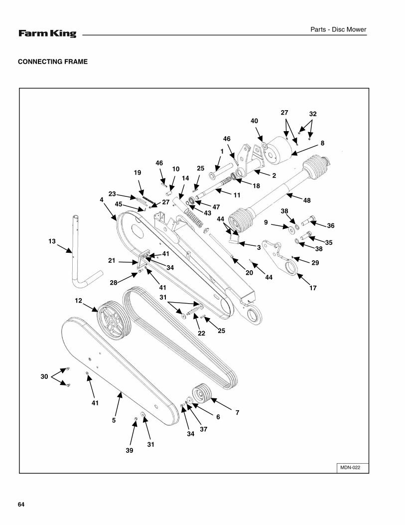
MDN-022
76
3734
3139
5
41
30
12
13
21
284131
22 25
2044
17
29
3835
36
3
9
38
48
4347
1118
2
8
322740
46
1
25
1410
46
27
19
23
454
44
34
41
64
Parts - Disc Mower
ITEM PART NUMBER DESCRIPTION MDN 4 QTY
MDN 5 QTY
MDN 6 QTY
MDN 7 QTY
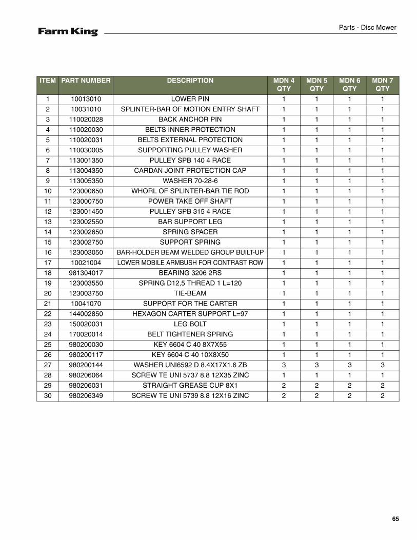
1 10013010 LOWER PIN 1 1 1 1
2 10031010 SPLINTER-BAR OF MOTION ENTRY SHAFT 1 1 1 1
3 110020028 BACK ANCHOR PIN 1 1 1 1
4 110020030 BELTS INNER PROTECTION 1 1 1 1
5 110020031 BELTS EXTERNAL PROTECTION 1 1 1 1
6 110030005 SUPPORTING PULLEY WASHER 1 1 1 1
7 113001350 PULLEY SPB 140 4 RACE 1 1 1 1
8 113004350 CARDAN JOINT PROTECTION CAP 1 1 1 1
9 113005350 WASHER 70-28-6 1 1 1 1
10 123000650 WHORL OF SPLINTER-BAR TIE ROD 1 1 1 1
11 123000750 POWER TAKE OFF SHAFT 1 1 1 1
12 123001450 PULLEY SPB 315 4 RACE 1 1 1 1
13 123002550 BAR SUPPORT LEG 1 1 1 1
14 123002650 SPRING SPACER 1 1 1 1
15 123002750 SUPPORT SPRING 1 1 1 1
16 123003050 BAR-HOLDER BEAM WELDED GROUP BUILT-UP 1 1 1 1
17 10021004 LOWER MOBILE ARMBUSH FOR CONTRAST ROW 1 1 1 1
18 981304017 BEARING 3206 2RS 1 1 1 1
19 123003550 SPRING D12,5 THREAD 1 L=120 1 1 1 1
20 123003750 TIE-BEAM 1 1 1 1
21 10041070 SUPPORT FOR THE CARTER 1 1 1 1
22 144002850 HEXAGON CARTER SUPPORT L=97 1 1 1 1
23 150020031 LEG BOLT 1 1 1 1
24 170020014 BELT TIGHTENER SPRING 1 1 1 1
25 980200030 KEY 6604 C 40 8X7X55 1 1 1 1
26 980200117 KEY 6604 C 40 10X8X50 1 1 1 1
27 980200144 WASHER UNI6592 D 8.4X17X1.6 ZB 3 3 3 3
28 980206064 SCREW TE UNI 5737 8.8 12X35 ZINC 1 1 1 1
29 980206031 STRAIGHT GREASE CUP 8X1 2 2 2 2
30 980206349 SCREW TE UNI 5739 8.8 12X16 ZINC 2 2 2 2
65
Parts - Disc Mower
CONNECTING FRAME (CONT’D)
MDN-022
76
3734
3139
5
41
30
12
13
21
284131
22 25
2044
17
29
3835
36
3
9
38
48
4347
1118
2
8
322740
46
1
25
1410
46
27
19
23
454
44
34
41
66
Parts - Disc Mower
ITEM PART NUMBER DESCRIPTION MDN 4 QTY
MDN 5 QTY
MDN 6 QTY
MDN 7 QTY
31 980206100 WASHER UNI6593 D 14X48X3 ZB 3 3 3 3
32 980206142 NUT METALBLOC M 8 ZB 2 2 2 2
33 980206437 SCREW TE UNI 5739 8.8 8X25 ZINC 2 2 2 2
34 980206441 SCREW TE UNI 5739 8.8 12X30 ZINC 2 2 2 2
35 980206447 SCREW TE UNI 5737 8.8 27X80 ZB 1 1 1 1
36 980206452 SCREW TE UNI 5737 8.8 27X110 ZB 1 1 1 1
37 980206552 WASHER GROWER M12 ZB 1 1 1 1
38 980206559 WASHER GROWER D 27 RINF. ZB 2 2 2 2
39 980206631 NUT UNI 5721 6.8 PG 12 ZB 1 1 1 1
40 980206698 WASHER UNI6592 D 37X66X5 ZB 1 1 1 1
41 980206704 WASHER UNI6592 D 13X24X2.5 ZB 4 4 4 4
42 980913660 BELT SBP 2840 4 4 4 4
43 981108032 OUTER RING UNI 7435 C70 30 1 1 1 1
44 981108210 ELASTIC PIN UNI 6873 6X36 ZB 3 3 3 3
45 981108211 ELASTIC PIN UNI 6873 3,5X26 ZB 1 1 1 1
46 981108604 ELASTIC PIN UNI 6873 10X60 ZINC 2 2 2 2
47 981304028 BEARING 6206 2RS 1 1 1 1
48 989931010 CARDAN 8C26034CE007002 1 1 1 1
67
Parts - Disc Mower
PROTECTIONS SHIELDS
MDN-023
22
21
4
21
242523
11
1220
15
2012
11
13
7 10
12
12
3
12
1814
16
17
14
18
12
7
10
8
9
19
5 6
7
12
11
2
68
Parts - Disc Mower
ITEM PART NUMBER DESCRIPTION MDN 4 QTY
MDN 5 QTY
MDN 6 QTY
MDN 7 QTY
1
10011005 MAIN CHASSIS MDN 4 1
10011015 MAIN CHASSIS MDN 5 1
10011020 MAIN CHASSIS MDN 6 1
10011025 MAIN CHASSIS MDN 7 1
2
10043135 PROTECTIONS BACK CHASSIS MDN 4 1
10043125 PROTECTIONS BACK CHASSIS MDN 5 1
10043115 PROTECTIONS BACK CHASSIS MDN 6 1
10043105 PROTECTIONS BACK CHASSIS MDN 7 1
3
10043130 FRONT CHASSIS MDN 4 1
10043120 FRONT CHASSIS MDN 5 1
10043110 FRONT CHASSIS MDN 6 1
10043100 FRONT CHASSIS MDN 7 1
4 113005460 CHASSIS SUPPORT COLUMN 1 1 1 1
5 980206377 SCREW TE UNI 5739 8.8 10X35 ZB 1 1 1 1
6 980206245 WASHER M10 UNI6592 ZB 3 3 3 3
7 980205250 NUT METALBLOC M10 ZB 3 3 3 3
8 980305125 SCREW TE UNI 5739 10.9 12X30 4 4 4 4
9 85501187 CUP SPRING 25X12,2X1,5 4 4 4 4
10 980206200 SCREW TE UNI 5737 8.8 10X65 ZB 2 2 2 2
11 980206426 SCREW TE UNI 5739 8X20 ZINC 5 5 5 5
12 980206142 NUT METALBLOC M8 ZINC 9 9 9 9
13 981100300 FORK WITH D4 THREAD 1 1 1 1
14 980206220 SCREW TB C/FLANGE TORX 8X20 ZINC 2 2 2 2
15 150080005 TRACTION SPRING Ø21X152 1 1 1 1
16
/ PROTECTION BURLAP MDN 4 1
124000650 PROTECTION BURLAP MDN 5 1
134000650 PROTECTION BURLAP MDN 6 1
144002950 PROTECTION BURLAP MDN 7 1
17
113004450 LINE FOR BURLAP STRENGTHENING MDN 4 1
123003950 LINE FOR BURLAP STRENGTHENING MDN 5 1
133001450 LINE FOR BURLAP STRENGTHENING MDN 6 1
143000650 LINE FOR BURLAP STRENGTHENING MDN 7 1
18 980200144 WASHER UNI6592 D 8.4X17X1.6 ZB 2 2 2 2
19 980206352 SCREW TE UNI 5739 8.8 10X30 ZB 2 2 2 2
20 980206096 SCREW TE UNI 5739 8.8 8X30 ZB 2 2 2 2
21 980206613 NUT METALBLOC M12 ZINC 4 4 4 4
22 980206435 SCREW TE UNI 5739 8.8 12X35 ZB 2 2 2 2
23 980205551 SCREW TE UNI 5737 8.8 12X100 ZB 2 2 2 2
24 113005550 SUPPORT COLUMN ATTACK 1 1 1 1
25 980206704 WASHER UNI6592 D 13X24X2.5 ZB 2 2 2 2
69
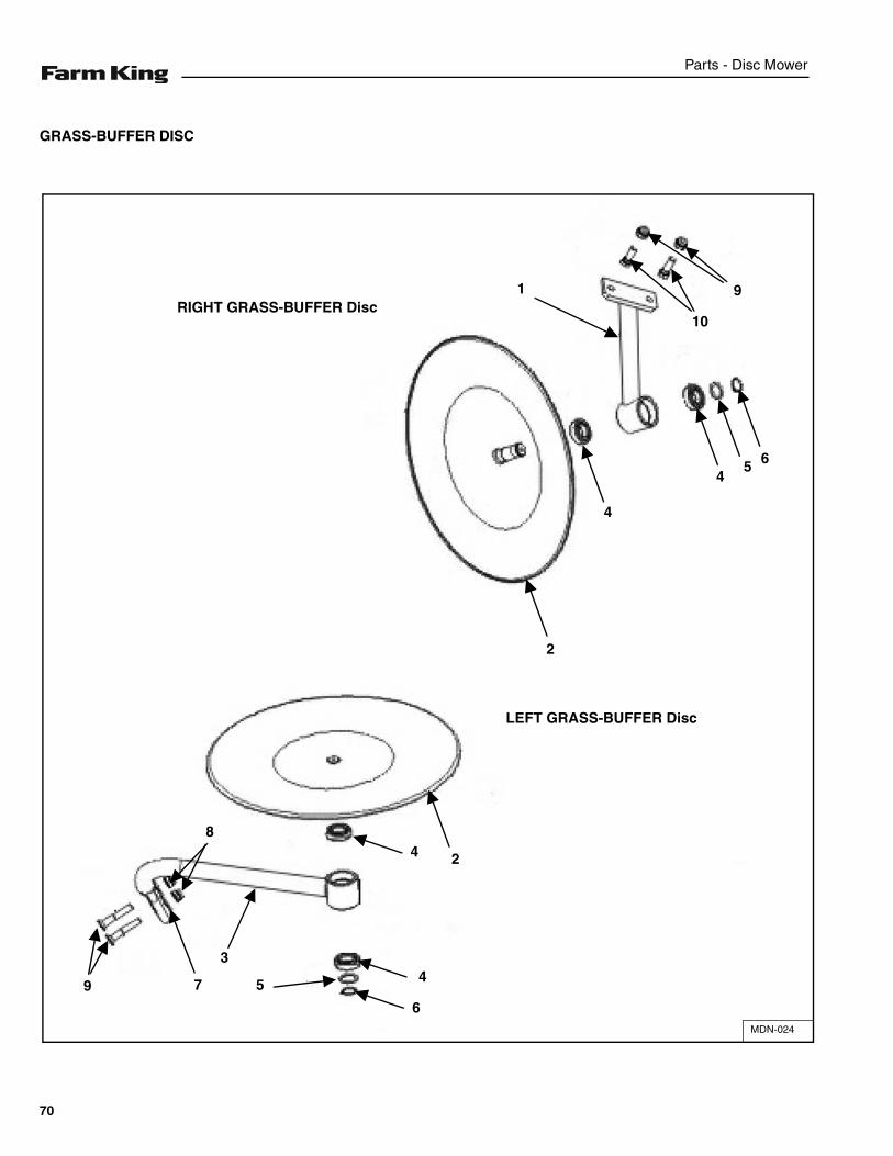
Parts - Disc Mower
GRASS-BUFFER DISC
MDN-024
1RIGHT GRASS-BUFFER Disc
LEFT GRASS-BUFFER Disc
10
9
654
4
2
24
4
6
5
3
9
8
7
70
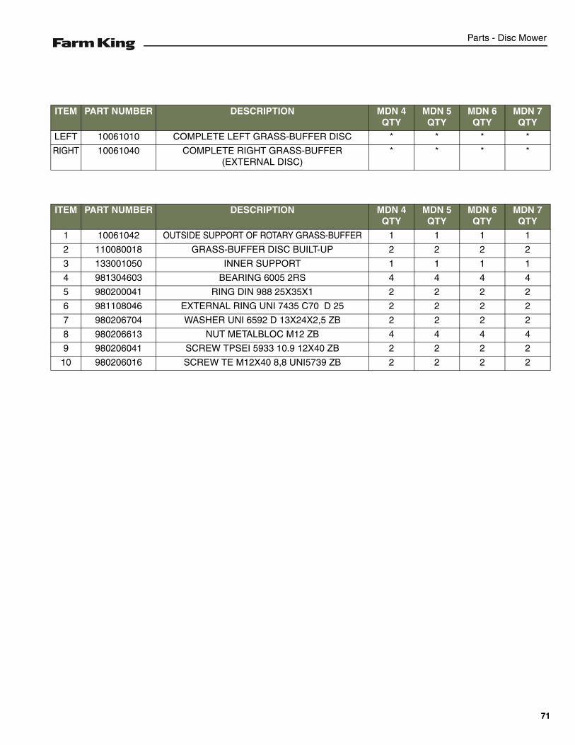
Parts - Disc Mower
ITEM PART NUMBER DESCRIPTION MDN 4 QTY
MDN 5 QTY
MDN 6 QTY
MDN 7 QTY
LEFT 10061010 COMPLETE LEFT GRASS-BUFFER DISC * * * *
RIGHT 10061040 COMPLETE RIGHT GRASS-BUFFER (EXTERNAL DISC)
* * * *
ITEM PART NUMBER DESCRIPTION MDN 4 QTY
MDN 5 QTY
MDN 6 QTY
MDN 7 QTY
1 10061042 OUTSIDE SUPPORT OF ROTARY GRASS-BUFFER 1 1 1 1
2 110080018 GRASS-BUFFER DISC BUILT-UP 2 2 2 2
3 133001050 INNER SUPPORT 1 1 1 1
4 981304603 BEARING 6005 2RS 4 4 4 4
5 980200041 RING DIN 988 25X35X1 2 2 2 2
6 981108046 EXTERNAL RING UNI 7435 C70 D 25 2 2 2 2
7 980206704 WASHER UNI 6592 D 13X24X2,5 ZB 2 2 2 2
8 980206613 NUT METALBLOC M12 ZB 4 4 4 4
9 980206041 SCREW TPSEI 5933 10.9 12X40 ZB 2 2 2 2
10 980206016 SCREW TE M12X40 8,8 UNI5739 ZB 2 2 2 2
71
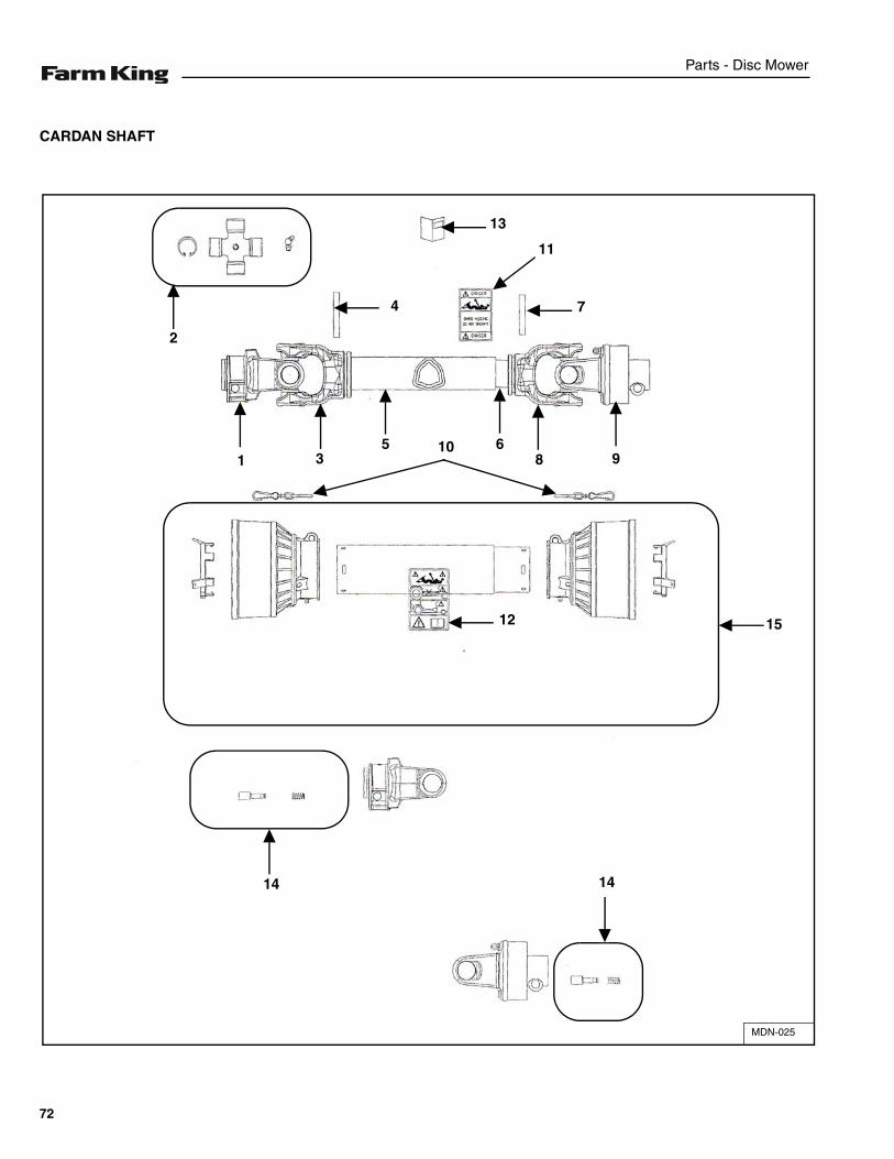
Parts - Disc Mower
CARDAN SHAFT
MDN-025
4
2
1 35 10 6
8 9
7
11
13
12
14 14
15
72
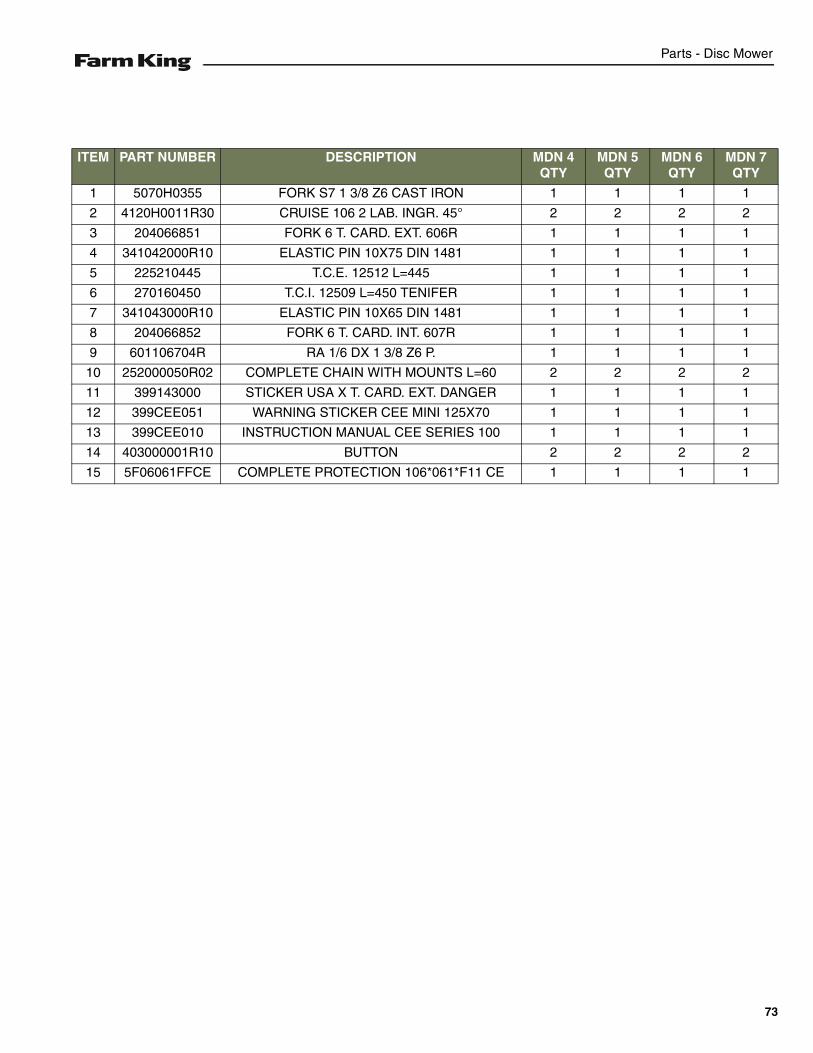
Parts - Disc Mower
ITEM PART NUMBER DESCRIPTION MDN 4 QTY
MDN 5 QTY
MDN 6 QTY
MDN 7 QTY
1 5070H0355 FORK S7 1 3/8 Z6 CAST IRON 1 1 1 1
2 4120H0011R30 CRUISE 106 2 LAB. INGR. 45° 2 2 2 2
3 204066851 FORK 6 T. CARD. EXT. 606R 1 1 1 1
4 341042000R10 ELASTIC PIN 10X75 DIN 1481 1 1 1 1
5 225210445 T.C.E. 12512 L=445 1 1 1 1
6 270160450 T.C.I. 12509 L=450 TENIFER 1 1 1 1
7 341043000R10 ELASTIC PIN 10X65 DIN 1481 1 1 1 1
8 204066852 FORK 6 T. CARD. INT. 607R 1 1 1 1
9 601106704R RA 1/6 DX 1 3/8 Z6 P. 1 1 1 1
10 252000050R02 COMPLETE CHAIN WITH MOUNTS L=60 2 2 2 2
11 399143000 STICKER USA X T. CARD. EXT. DANGER 1 1 1 1
12 399CEE051 WARNING STICKER CEE MINI 125X70 1 1 1 1
13 399CEE010 INSTRUCTION MANUAL CEE SERIES 100 1 1 1 1
14 403000001R10 BUTTON 2 2 2 2
15 5F06061FFCE COMPLETE PROTECTION 106*061*F11 CE 1 1 1 1
73
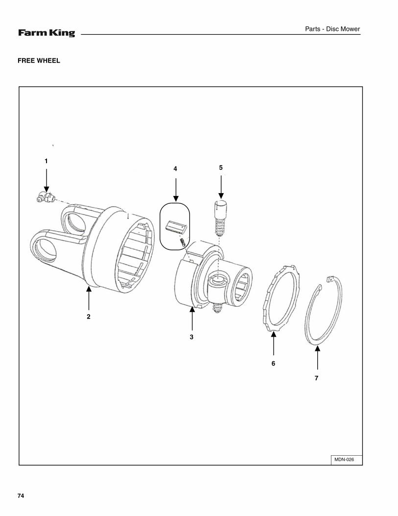
Parts - Disc Mower
FREE WHEEL
MDN-026
7
6
541
2
3
74

Parts - Disc Mower
ITEM PART NUMBER DESCRIPTION MDN 4 QTY
MDN 5 QTY
MDN 6 QTY
MDN 7 QTY
1 348014000R20 GREASE NIPPLE 8X1.25X90 ART.36 1 1 1 1
2 418061201 EXTERNAL BODY RA1 WITH FORK D.106 1 1 1 1
3 5130C0301 HUB RA1DX 1 3/8 Z6 BUTTON, PLATE 1 1 1 1
4 4210C0001R03 OVERHEAD PLATES RA1 3 3 3 3
5 403000001R10 BUTTON 1 1 1 1
6 246000132R02 DISC CLOSURE X RA RIGHT 1 1 1 1
7 338005000R20 ELASTIC RING INT. 82X2,50 DIN 472/1 1 1 1 1
75
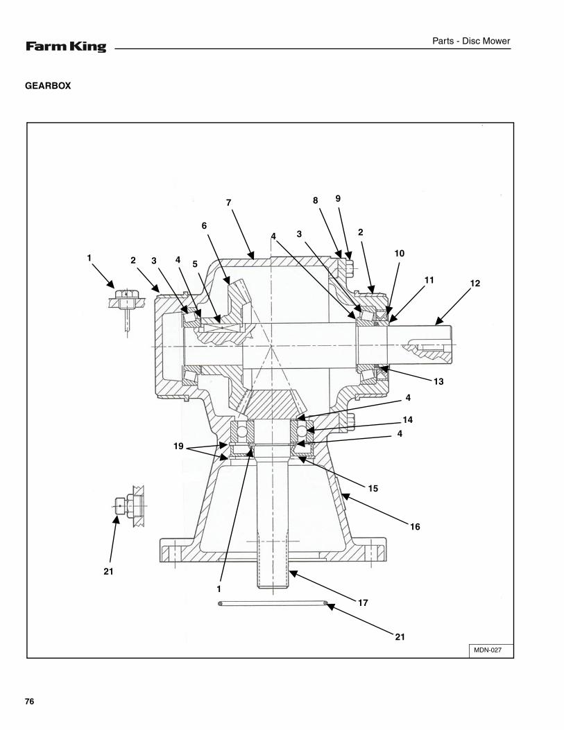
Parts - Disc Mower
GEARBOX
MDN-027
1 2 3 4 5
6
7
4 3
8 9
2
10
11 12
19
4
14
4
15
16
17
21
1
21
13
76
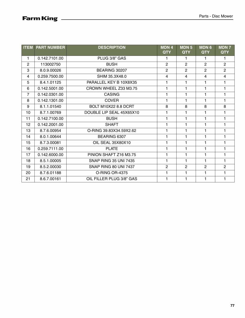
Parts - Disc Mower
ITEM PART NUMBER DESCRIPTION MDN 4 QTY
MDN 5 QTY
MDN 6 QTY
MDN 7 QTY
1 0.142.7101.00 PLUG 3/8” GAS 1 1 1 1
2 113002750 BUSH 2 2 2 2
3 8.0.9.00026 BEARING 30207 2 2 2 2
4 0.259.7500.00 SHIM 35.3X48.0 4 4 4 4
5 8.4.1.01125 PARALLEL KEY B 10X8X35 1 1 1 1
6 0.142.5001.00 CROWN WHEEL Z33 M3.75 1 1 1 1
7 0.142.0301.00 CASING 1 1 1 1
8 0.142.1301.00 COVER 1 1 1 1
9 8.1.1.01540 BOLT M10X22 8.8 DCRT 8 8 8 8
10 8.7.1.00769 DOUBLE LIP SEAL 45X65X10 1 1 1 1
11 0.142.7100.00 BUSH 1 1 1 1
12 0.142.2001.00 SHAFT 1 1 1 1
13 8.7.6.00954 O-RING 39.83X34.59X2.62 1 1 1 1
14 8.0.1.00644 BEARING 6307 1 1 1 1
15 8.7.3.00081 OIL SEAL 35X80X10 1 1 1 1
16 0.259.7111.00 PLATE 1 1 1 1
17 0.142.6000.00 PINION SHAFT Z16 M3.75 1 1 1 1
18 8.5.1.00005 SNAP RING 35 UNI 7435 1 1 1 1
19 8.5.2.00030 SNAP RING 80 UNI 7437 2 2 2 2
20 8.7.6.01188 O-RING OR-4375 1 1 1 1
21 8.6.7.00161 OIL FILLER PLUG 3/8” GAS 1 1 1 1
77

Parts - Disc Mower
78
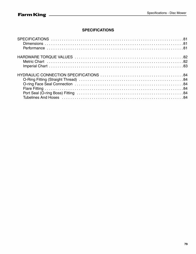
Specifications - Disc Mower
SPECIFICATIONS
SPECIFICATIONS . . . . . . . . . . . . . . . . . . . . . . . . . . . . . . . . . . . . . . . . . . . . . . . . . . . . . . . . . . . . . . 81Dimensions . . . . . . . . . . . . . . . . . . . . . . . . . . . . . . . . . . . . . . . . . . . . . . . . . . . . . . . . . . . . . . . . . 81Performance . . . . . . . . . . . . . . . . . . . . . . . . . . . . . . . . . . . . . . . . . . . . . . . . . . . . . . . . . . . . . . . . 81
HARDWARE TORQUE VALUES . . . . . . . . . . . . . . . . . . . . . . . . . . . . . . . . . . . . . . . . . . . . . . . . . . . 82Metric Chart . . . . . . . . . . . . . . . . . . . . . . . . . . . . . . . . . . . . . . . . . . . . . . . . . . . . . . . . . . . . . . . . 82Imperial Chart . . . . . . . . . . . . . . . . . . . . . . . . . . . . . . . . . . . . . . . . . . . . . . . . . . . . . . . . . . . . . . . 83
HYDRAULIC CONNECTION SPECIFICATIONS . . . . . . . . . . . . . . . . . . . . . . . . . . . . . . . . . . . . . . .84O-Ring Fitting (Straight Thread) . . . . . . . . . . . . . . . . . . . . . . . . . . . . . . . . . . . . . . . . . . . . . . . . .84O-ring Face Seal Connection . . . . . . . . . . . . . . . . . . . . . . . . . . . . . . . . . . . . . . . . . . . . . . . . . . . 84Flare Fitting . . . . . . . . . . . . . . . . . . . . . . . . . . . . . . . . . . . . . . . . . . . . . . . . . . . . . . . . . . . . . . . . . 84Port Seal (O-ring Boss) Fitting . . . . . . . . . . . . . . . . . . . . . . . . . . . . . . . . . . . . . . . . . . . . . . . . . . 84Tubelines And Hoses . . . . . . . . . . . . . . . . . . . . . . . . . . . . . . . . . . . . . . . . . . . . . . . . . . . . . . . . . 84
79

Specifications - Disc Mower
80
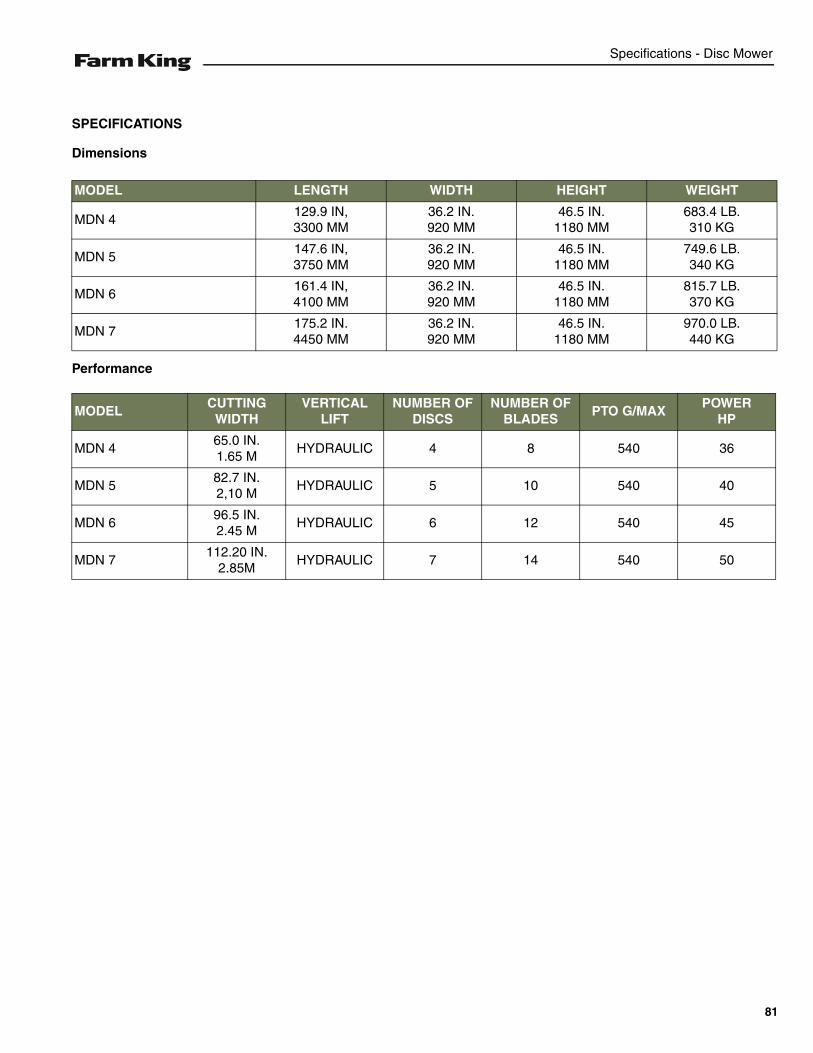
Specifications - Disc Mower
SPECIFICATIONS
Dimensions
Performance
MODEL LENGTH WIDTH HEIGHT WEIGHT
MDN 4129.9 IN,3300 MM
36.2 IN.920 MM
46.5 IN.1180 MM
683.4 LB.310 KG
MDN 5147.6 IN,3750 MM
36.2 IN.920 MM
46.5 IN.1180 MM
749.6 LB.340 KG
MDN 6161.4 IN,4100 MM
36.2 IN.920 MM
46.5 IN.1180 MM
815.7 LB.370 KG
MDN 7175.2 IN.4450 MM
36.2 IN.920 MM
46.5 IN.1180 MM
970.0 LB.440 KG
MODELCUTTING
WIDTHVERTICAL
LIFTNUMBER OF
DISCSNUMBER OF
BLADESPTO G/MAX
POWER HP
MDN 465.0 IN.1.65 M
HYDRAULIC 4 8 540 36
MDN 582.7 IN.2,10 M
HYDRAULIC 5 10 540 40
MDN 696.5 IN.2.45 M
HYDRAULIC 6 12 540 45
MDN 7112.20 IN.
2.85MHYDRAULIC 7 14 540 50
81
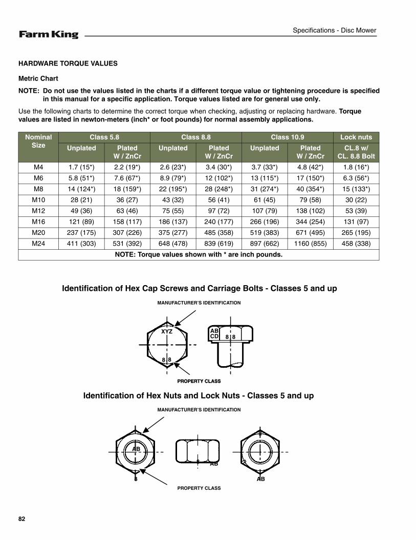
Specifications - Disc Mower
HARDWARE TORQUE VALUES
Metric Chart
NOTE: Do not use the values listed in the charts if a different torque value or tightening procedure is specifiedin this manual for a specific application. Torque values listed are for general use only.
Use the following charts to determine the correct torque when checking, adjusting or replacing hardware. Torquevalues are listed in newton-meters (inch* or foot pounds) for normal assembly applications.
Nominal Size
Class 5.8 Class 8.8 Class 10.9 Lock nuts
Unplated PlatedW / ZnCr
Unplated PlatedW / ZnCr
Unplated PlatedW / ZnCr
CL.8 w/CL. 8.8 Bolt
M4 1.7 (15*) 2.2 (19*) 2.6 (23*) 3.4 (30*) 3.7 (33*) 4.8 (42*) 1.8 (16*)
M6 5.8 (51*) 7.6 (67*) 8.9 (79*) 12 (102*) 13 (115*) 17 (150*) 6.3 (56*)
M8 14 (124*) 18 (159*) 22 (195*) 28 (248*) 31 (274*) 40 (354*) 15 (133*)
M10 28 (21) 36 (27) 43 (32) 56 (41) 61 (45) 79 (58) 30 (22)
M12 49 (36) 63 (46) 75 (55) 97 (72) 107 (79) 138 (102) 53 (39)
M16 121 (89) 158 (117) 186 (137) 240 (177) 266 (196) 344 (254) 131 (97)
M20 237 (175) 307 (226) 375 (277) 485 (358) 519 (383) 671 (495) 265 (195)
M24 411 (303) 531 (392) 648 (478) 839 (619) 897 (662) 1160 (855) 458 (338)
NOTE: Torque values shown with * are inch pounds.
Identification of Hex Cap Screws and Carriage Bolts - Classes 5 and up
XYZ
8 8
8 8ABCD
MANUFACTURER’S IDENTIFICATION
PROPERTY CLASS
Identification of Hex Nuts and Lock Nuts - Classes 5 and up
PROPERTY CLASS
MANUFACTURER’S IDENTIFICATION
PROPERTY CLASS
AB
AB8
8 AB
82

Specifications - Disc Mower
HARDWARE TORQUE VALUES (CONT’D)
Imperial Chart
NOTE: Do not use the values listed in the charts if a different torque value or tightening procedure is specifiedin this manual for a specific application. Torque values listed are for general use only.
Use the following charts to determine the correct torque when checking, adjusting or replacing hardware. Torquevalues are listed in newton-meters (inch* or foot pounds) for normal assembly applications.
Nominal Size
SAE Grade 5 SAE Grade 8 LOCK NUTS
Unplatedor
Plated Silver
PlatedW / ZnCr
Gold
Unplatedor
Plated Silver
PlatedW / ZnCr
Gold
Unplatedor
Plated Silver
PlatedW / ZnCr
Gold
GradeW / Gr. 5
Bolt
GradeW / Gr. 8
Bolt
1/4 6.2 (55*) 8.1 (72*) 9.7 (86*) 12.6 (112*) 13.6 (121*) 17.7 (157*) 6.9 (61*) 9.8 (86*)
5/16 13 (115*) 17 (149*) 20 (178*) 26 (229*) 28 (250*) 37 (324*) 14 (125*) 20 (176*)
3/8 23 (17) 30 (22) 35 (26) 46 (34) 50 (37) 65 (48) 26 (19) 35 (26)
7/16 37 (27) 47 (35) 57 (42) 73 (54) 80 (59) 104 (77) 41 (30) 57 (42)
1/2 57 (42) 73 (54) 87 (64) 113 (83) 123 (91) 159 (117) 61 (45) 88 (64)
9/16 81 (60) 104 (77) 125 (92) 163 (120) 176 (130) 229 (169) 88 (65) 125 (92)
5/8 112 (83) 145 (107) 174 (128) 224 (165) 244 (180) 316 (233) 122 (90) 172 (127)
3/4 198 (146) 256 (189) 306 (226) 397 (293) 432 (319) 560 (413) 217 (160) 306 (226)
7/8 193 (142) 248 (183) 495 (365) 641 (473) 698 (515) 904 (667) 350 (258) 494 (364)
1 289 (213) 373 (275) 742 (547) 960 (708) 1048 (773) 1356 (1000) 523 (386) 739 (545)
NOTE: Torque values shown with * are inch pounds.
Identification of Hex Cap Screws and Carriage Bolts
Identification of Hex Nuts and Lock Nuts
SAE GRADE 2 BOLTS
SAE GRADE 5 BOLTS
SAE GRADE 8 BOLTS
SAE GRADE 2 NUTS
SAE GRADE 5 NUTS
SAE GRADE 8 NUTS
B
Grade A - No Notches
Grade B - One Circumferential Notch
Grade C - Two Circumferential Notches
Grade A - No Mark
Grade B - Letter B
Grade C - Letter C
Grade A - No Marks
Grade B - Three Marks
Grade C - Six Marks
(Marks not always located at corners)
83
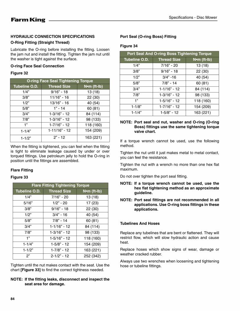
Specifications - Disc Mower
HYDRAULIC CONNECTION SPECIFICATIONS
O-Ring Fitting (Straight Thread)
Lubricate the O-ring before installing the fitting. Loosenthe jam nut and install the fitting. Tighten the jam nut untilthe washer is tight against the surface.
O-ring Face Seal Connection
Figure 32
When the fitting is tightened, you can feel when the fittingis tight to eliminate leakage caused by under or overtorqued fittings. Use petroleum jelly to hold the O-ring inposition until the fittings are assembled.
Flare Fitting
Figure 33
Tighten until the nut makes contact with the seat. Use thechart [Figure 33] to find the correct tightness needed.
NOTE: If the fitting leaks, disconnect and inspect theseat area for damage.
Port Seal (O-ring Boss) Fitting
Figure 34
NOTE: Port seal and nut, washer and O-ring (O-ringBoss) fittings use the same tightening torquevalve chart.
If a torque wrench cannot be used, use the followingmethod.
Tighten the nut until it just makes metal to metal contact,you can feel the resistance.
Tighten the nut with a wrench no more than one hex flatmaximum.
Do not over tighten the port seal fitting.
NOTE: If a torque wrench cannot be used, use thehex flat tightening method as an approximateguideline.
NOTE: Port seal fittings are not recommended in allapplications. Use O-ring boss fittings in theseapplications.
Tubelines And Hoses
Replace any tubelines that are bent or flattened. They willrestrict flow, which will slow hydraulic action and causeheat.
Replace hoses which show signs of wear, damage orweather cracked rubber.
Always use two wrenches when loosening and tighteninghose or tubeline fittings.
O-ring Face Seal Tightening TorqueTubeline O.D. Thread Size N•m (ft-lb)
1/4” 9/16” - 18 13 (18)3/8” 11/16” - 16 22 (30)1/2” 13/16” - 16 40 (54)5/8” 1” - 14 60 (81)3/4” 1-3/16” - 12 84 (114)7/8” 1-3/16” - 12 98 (133)1” 1-7/16” - 12 118 (160)
1-1/4” 1-11/16” - 12 154 (209)
1-1/2” 2” - 12 163 (221)
Flare Fitting Tightening Torque
Tubeline O.D. Thread Size N•m (ft-lb)
1/4” 7/16” - 20 13 (18)
5/16” 1/2” - 20 17 (23)
3/8” 9/16” - 18 22 (30)
1/2” 3/4” - 16 40 (54)
5/8” 7/8” - 14 60 (81)
3/4” 1-1/16” - 12 84 (114)
7/8” 1-3/16” - 12 98 (133)
1” 1-5/16” - 12 118 (160)
1-1/4” 1-5/8” - 12 154 (209)
1-1/2” 1-7/8” - 12 163 (221)
2” 2-1/2” - 12 252 (342)
Port Seal And O-ring Boss Tightening Torque
Tubeline O.D. Thread Size N•m (ft-lb)
1/4” 7/16” - 20 13 (18)
3/8” 9/16” - 18 22 (30)
1/2” 3/4” -16 40 (54)
5/8” 7/8” - 14 60 (81)
3/4” 1-1/16” - 12 84 (114)
7/8” 1-3/16” - 12 98 (133)
1” 1-5/16” - 12 118 (160)
1-1/8” 1-7/16” - 12 154 (209)
1-1/4” 1-5/8” - 12 163 (221)
84

Warranty - Disc Mower
WARRANTY
WARRANTY . . . . . . . . . . . . . . . . . . . . . . . . . . . . . . . . . . . . . . . . . . . . . . . . . . . . . . . . . . . . . . . . . . . 87
85

Warranty - Disc Mower
86
Warranty - Disc Mower
WARRANTY
Limited Warranty
BASE LIMITED WARRANTY
Farm King provides this warranty only to original retail purchasers of its products. Farm King warrants to suchpurchasers that all Farm King manufactured parts and components used and serviced as provided for in theOperator’s Manual shall be free from defects in materials and workmanship for a period following delivery tothe original retail purchaser of one (1) year. This limited warranty applies only to those parts and componentsmanufactured by Farm King. Parts and components manufactured by others are subject to theirmanufacturer’s warranties, if any.
Farm King will fulfill this limited warranty by, at its option, repairing or replacing any covered part that isdefective or is the result of improper workmanship, provided that the part is returned to Farm King within thirty(30) days of the date that such defect or improper workmanship is, or should have been, discovered. Partsmust be returned through the selling representative and the buyer must prepay transportation charges.
Farm King will not be responsible for repairs or replacements that are necessitated, in whole or part, by theuse of parts not manufactured by or obtained from Farm King. Under no circumstances are component partswarranted against normal wear and tear. There is no warranty on product pump seals, product pump bearings,rubber product hoses, pressure gauges, or other components that require replacement as part of normalmaintenance.
REPAIR PARTS LIMITED WARRANTY
Farm King warrants genuine Farm King replacement parts purchased after the expiration of the Farm KingLimited Warranty, and used and serviced as provided for in the Operator’s Manual, to be free from defects inmaterials or workmanship for a period of thirty (30) days from the invoice date for the parts. Farm King willfulfill this limited warranty by, at its option, repairing or replacing any covered part that is defective or is theresult of improper workmanship, provided that the part is returned to Farm King within thirty (30) days of thedate that such defect or improper workmanship is, or should have been, discovered. Such parts must beshipped to the Farm King factory at the purchaser’s expense.
WHAT IS NOT COVERED
Under no circumstances does this limited warranty cover any components or parts that have been subject tothe following: negligence; alteration or modification not approved by Farm King; misuse; improper storage;lack of reasonable and proper maintenance, service, or repair; normal wear; damage from failure to followoperating instructions; accident; and/or repairs that have been made with parts other than thosemanufactured, supplied, and / or authorized by Farm King.
AUTHORIZED DEALER AND LABOR COSTS
Repairs eligible for labor under this limited warranty must be made by Farm King or an authorized Farm Kingdealer. Farm King retains the exclusive discretion to determine whether it will pay labor costs for warrantyrepairs or replacements, and the amount of such costs that it will pay and the time in which the repairs will bemade. If Farm King determines that it will pay labor costs for warranty work, it will do so by issuing a credit tothe dealer’s or distributor’s account. Farm King will not approve or pay invoices sent for repairs that Farm Kinghas not previously approved. Warranty service does not extend the original term of this limited warranty.
87
Warranty - Disc Mower
Limited Warranty
WARRANTY REQUIREMENTS
To be covered by warranty, each new product must be registered with Farm King within thirty (30) days ofdelivery to original retail purchaser. If the customer decides to purchase replacement components before thewarranty disposition of such components is determined, Farm King will bill the customer for suchcomponents and then credit the replacement invoice for those components later determined to be covered bythis limited warranty. Any such replacement components that are determined not be covered by this limitedwarranty will be subject to the terms of the invoice and shall be paid for by the purchaser.
EXCLUSIVE EFFECT OF WARRANTY AND LIMITATION OF LIABILITY
TO THE EXTENT PERMITTED BY LAW, FARM KING DISCLAIMS ANY WARRANTIES, REPRESENTATIONS, ORPROMISES, EXPRESS OR IMPLIED, AS TO THE QUALITY, PERFORMANCE, OR FREEDOM FROM DEFECT OFTHE COMPONENTS AND PARTS COVERED BY THIS WARRANTY AND NOT SPECIFICALLY PROVIDED FORHEREIN.
TO THE EXTENT PERMITTED BY LAW, FARM KING DISCLAIMS ANY IMPLIED WARRANTIES OFMERCHANTABILITY AND FITNESS FOR A PARTICULAR PURPOSE ON ITS PRODUCTS COVERED HEREIN,AND DISCLAIMS ANY RELIANCE BY THE PURCHASER ON FARM KING’S SKILL OR JUDGMENT TO SELECTOR FURNISH GOODS FOR ANY PARTICULAR PURPOSE. THE PURCHASER’S ONLY AND EXCLUSIVEREMEDIES IN CONNECTION WITH THE BREACH OR PERFORMANCE OF ANY WARRANTY ON FARM KING’SPRODUCTS ARE THOSE SET FORTH HEREIN. IN NO EVENT SHALL FARM KING BE LIABLE FOR INCIDENTALOR CONSEQUENTIAL DAMAGES (INCLUDING, BY WAY OF EXAMPLE ONLY AND NOT LIMITATION, LOSS OFCROPS, LOSS OF PROFITS OR REVENUE, OTHER COMMERCIAL LOSSES, INCONVENIENCE, OR COST OFREPLACEMENT OF RENTAL EQUIPMENT). IN NO EVENT SHALL FARM KING’S CONTRACT OR WARRANTYLIABILITY EXCEED THE PURCHASE PRICE OF THE PRODUCT. (Note that some states do not allow limitationson how long an implied warranty lasts or the exclusion or limitation of incidental or consequential damages,so the above limitations and exclusion may not apply to you.) This warranty gives you specific legal rights andyou may also have other rights, which vary from state to state.
Farm King neither assumes nor authorizes any person or entity, including its selling representatives, toassume any other obligations or liability in connections with the sale of covered equipment, or to make anyother warranties, representations, or promises, express or implied, as to the quality, performance, or freedomfrom defect of the components and parts covered herein. No one is authorized to alter, modify, or enlarge thislimited warranty, or its exclusions, limitations and reservations.
Corrections of defects and improper workmanship in the manner, and for the applicable time periods, providedfor herein shall constitute fulfillment of all responsibilities of Farm King to the purchaser, and Farm King shallnot be liable in negligence, contract, or on any other basis with respect to the subject equipment.
This limited warranty is subject to any existing conditions of supply which may directly affect Farm King’sability to obtain materials or manufacturer replacement parts.
Buhler Industries Inc. reserves the right to make improvements in design or changes in specifications to itsproducts at anytime, without incurring any obligation to owners of units previously sold.
88
Alphabetical Index - Disc Mower
ALPHABETICAL INDEX
CARDAN SHAFT . . . . . . . . . . . . . . . . . . . . . 72CLEANING AND MAINTENANCE . . . . . . . . 46CONNECTING FRAME . . . . . . . . . . . . . . . . 64CUTTING GROUP . . . . . . . . . . . . . . . . . . . . 60EQUIPMENT DECALS AND SIGNS . . . . . . 18EQUIPMENT IDENTIFICATION . . . . . . . . . . 10FIRE PREVENTION . . . . . . . . . . . . . . . . . . . 15FREE WHEEL . . . . . . . . . . . . . . . . . . . . . . . 74GEARBOX . . . . . . . . . . . . . . . . . . . . . . . . . . 76GENERAL INFORMATION . . . . . . . . . . . . . 23GENERAL INFORMATION . . . . . . . . . . . . . 55GRASS-BUFFER DISC . . . . . . . . . . . . . . . . 70HARDWARE TORQUE VALUES . . . . . . . . . 82HYDRAULIC CONNECTION SPECIFICATIONS . . . . . . . . . . . . . . . . . . . . 84INITIAL SET-UP . . . . . . . . . . . . . . . . . . . . . . 26OWNER’S INFORMATION . . . . . . . . . . . . . . . 9PROTECTIONS SHIELDS . . . . . . . . . . . . . . 68SAFETY INSTRUCTIONS . . . . . . . . . . . . . . 13SAFETY SIGN-OFF FORM . . . . . . . . . . . . . 20SAFETY SIGNS (DECALS) . . . . . . . . . . . . . 17SERVICE SCHEDULE . . . . . . . . . . . . . . . . . 44SPECIFICATIONS . . . . . . . . . . . . . . . . . . . . 81STORAGE AND RETURN TO SERVICE . . . 52THREE POINT HITCH . . . . . . . . . . . . . . . . . 56TRANSPORTING . . . . . . . . . . . . . . . . . . . . . 38TROUBLESHOOTING . . . . . . . . . . . . . . . . . 43WARRANTY REGISTRATION FORM . . . . . . 5WARRANTY . . . . . . . . . . . . . . . . . . . . . . . . . 87
89

Alphabetical Index - Disc Mower
90


301 Mountain Street SouthMorden, Manitoba Canada R6M 1X7Toll Free: 1-888-FK-80001 E-mail: [email protected]
Equipment shown is subject to change without notice.©2016 Buhler Trading Inc. Printed in Canada TSX:BUI
www.farm-king.com


