22
Remote Control Swing Auger Kit For use with Kits Y1307, Y1330, 1684 and 16104 OPERATOR AND PARTS MANUAL SZ000924 SZ000885 shown
Remote Control Swing Auger KitFor use with Kits Y1307, Y1330, 1684 and 16104
OperatOr and parts Manual
SZ000924
SZ000885 shown

3
Table of Contents
Operation .....................................................................................................................................4• Safety ................................................................................................................................5• Recharging ........................................................................................................................6• Indicator Lights ................................................................................................................6• Teach ID Code ...................................................................................................................7• Cloning Transmitters ........................................................................................................7
Assembly ......................................................................................................................................8• Power Beyond Setup .......................................................................................................8• 16" Hopper Control Setup ...............................................................................................9• 13" Hopper Control Setup .............................................................................................13
Parts ............................................................................................................................................16• 16" Elec/Hyd Hopper Kit ................................................................................................16• 16" Elec/Hyd Hopper Kit Parts List ................................................................................17• 13" Elec/Hyd Hopper Kit ................................................................................................18• 13" Elec/Hyd Hopper Kit Parts List ................................................................................19
Options .......................................................................................................................................20
Manufacturer’s statement: for technical reasons Buhler Industries Inc. reserves the right to modify machinery design and specifications provided herein without any preliminary notice. Information provided herein is of descriptive nature. Performance quality may depend on soil fertility, applied agricultural techniques, weather conditions and other factors.
Table of Contents - Remote Control Swing Auger Kit - Y1307, Y1330, 1684 and 16104
4
Operation Instructions
1. Connect the plug to the Auxiliary Power port of the tractor. If the tractor is not equipped with an Auxiliary Power port, an optional power plug is available. The optional power plug will attach directly to the battery of the tractor. Turn the remote on by pressing the power button until both the red and green LEDs turn on. The green LED will flash rapidly when communication has been established with the receiver.
Notice: This kit is equipped for open- and closed-center hydraulic systems. Press the appropriate marked side of the open/close switch for the system your tractor has. Consult the operator's manual or your local dealer to determine the type of system your tractor has. Open-center is to be used on open-center, load sense, or power beyond equipped tractors. Closed-center is to be used on closed-center tractors.
2. Attach the hoses to the tractor, turn the appropriate tractor hydraulic flow control to minimum flow, activate the proper tractor hydraulic circuit and lock the tractor control lever into position. The tractor must have continuous hydraulic flow to the hopper control valve.
3. To move the hopper, depress the green or red arrows on the remote after turning the remote on, or depress the Left/Right manual switch above the valve block.
Notice: hydraulic oil flow from the tractor is controlled by a one-way check valve. If the hopper does not move with hopper control valve activated, reverse the flow from the tractor by switching the hoses at the tractor outlet or reversing the position of the tractor hydraulic control lever.
Notice: This optional powered wheel is not designed to push grain, rocks, dirt etc. when in use. The area the hopper moves over must be reasonably clear of all obstructions. If the wheels spin or the hopper “stalls out”, this is an indication that there is an obstruction to the hopper movement.
WARNINg Crushing Hazard: Failure to follow these guidelines may cause injury or death to the operator and/or bystanders.
Operation - Remote Control Swing Auger Kit - Y1307, Y1330, 1684 and 16104
5
Safety1. Always check the area the hopper will swing through. Do not operate the hopper power swing
if any people, animals or machinery will obstruct the motion of the hopper. The hopper can push, pinch, crush, knock down or run over the operator and/or bystanders if this instruction is not followed.
2. The operator of the hopper power swing control is the ONLY person to be in the area the hopper will swing through. Never operate the hopper power swing if anyone in addition to the operator is attempting to guide the hopper into position.
3. Never allow the hopper swing to guide the operator and/or bystanders into dangerous situations (i.e. rotating drives, auger flighting, moving vehicles etc.)
4. Never attempt to move the hopper by hand. Always use manual or remote controls of the electric/hydraulic kit.
5. Never lock manual control switch in a powered position. Manual control switch must always be allowed to return to a neutral position.
WARNINgEscaping high pressure hydraulic fluid can cause serious injury or death. Never check for hydraulic leaks using any part of the human body. Oil injection can occur, causing serious injury.
Operation - Remote Control Swing Auger Kit - Y1307, Y1330, 1684 and 16104
6
RechargingPlug the charging connector into the port at the top of the transmitter (remote control). Observe orientation and do not use force. A solid red LED indicates battery is charging. Once the internal battery is fully charged, the red LED will turn off and the green LED will turn on. A fully discharged unit will take up to 3 hours to recharge.
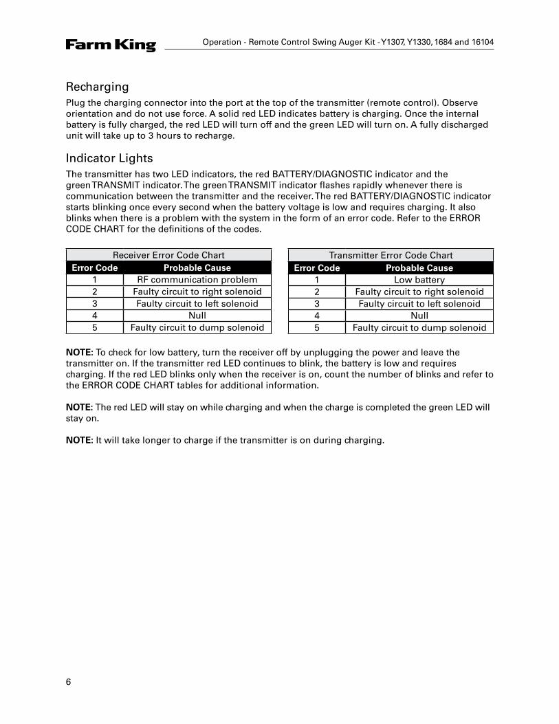
Indicator LightsThe transmitter has two LED indicators, the red BATTERY/DIAgNOSTIC indicator and the green TRANSMIT indicator. The green TRANSMIT indicator flashes rapidly whenever there is communication between the transmitter and the receiver. The red BATTERY/DIAgNOSTIC indicator starts blinking once every second when the battery voltage is low and requires charging. It also blinks when there is a problem with the system in the form of an error code. Refer to the ERROR CODE CHART for the definitions of the codes.
Receiver Error Code ChartError Code Probable Cause
1 RF communication problem2 Faulty circuit to right solenoid3 Faulty circuit to left solenoid4 Null5 Faulty circuit to dump solenoid
NOTE: To check for low battery, turn the receiver off by unplugging the power and leave the transmitter on. If the transmitter red LED continues to blink, the battery is low and requires charging. If the red LED blinks only when the receiver is on, count the number of blinks and refer to the ERROR CODE CHART tables for additional information. NOTE: The red LED will stay on while charging and when the charge is completed the green LED will stay on. NOTE: It will take longer to charge if the transmitter is on during charging.
Transmitter Error Code ChartError Code Probable Cause
1 Low battery2 Faulty circuit to right solenoid3 Faulty circuit to left solenoid4 Null5 Faulty circuit to dump solenoid
Operation - Remote Control Swing Auger Kit - Y1307, Y1330, 1684 and 16104
7
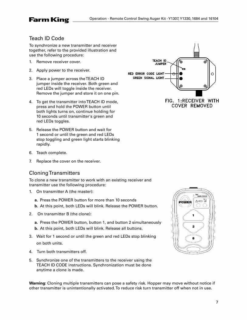
Teach ID CodeTo synchronize a new transmitter and receiver together, refer to the provided illustration and use the following procedure:
1. Remove receiver cover.
2. Apply power to the receiver.
3. Place a jumper across the TEACH ID jumper inside the receiver. Both green and red LEDs will toggle inside the receiver. Remove the jumper and store it on one pin.
4. To get the transmitter into TEACH ID mode, press and hold the POWER button until both lights turns on, continue holding for 10 seconds until transmitter's green and red LEDs toggles.
5. Release the POWER button and wait for 1 second or until the green and red LEDs stop toggling and green light starts blinking rapidly.
6. Teach complete.
7. Replace the cover on the receiver.
Cloning TransmittersTo clone a new transmitter to work with an existing receiver and transmitter use the following procedure:
1. On transmitter A (the master):
a. Press the POWER button for more than 10 secondsb. At this point, both LEDs will blink. Release the POWER button.
2. On transmitter B (the clone):
a. Press the POWER button, button 1, and button 2 simultaneouslyb. At this point, both LEDs will blink. Release all buttons.
3. Wait for 1 second or until the green and red LEDs stop blinking
on both units.
4. Turn both transmitters off.
5. Synchronize one of the transmitters to the receiver using the TEACH ID CODE instructions. Synchronization must be done anytime a clone is made.
Warning: Cloning multiple transmitters can pose a safety risk. Hopper may move without notice if other transmitter is unintentionally activated. To reduce risk turn transmitter off when not in use.
Operation - Remote Control Swing Auger Kit - Y1307, Y1330, 1684 and 16104
8
Assembly Instructions
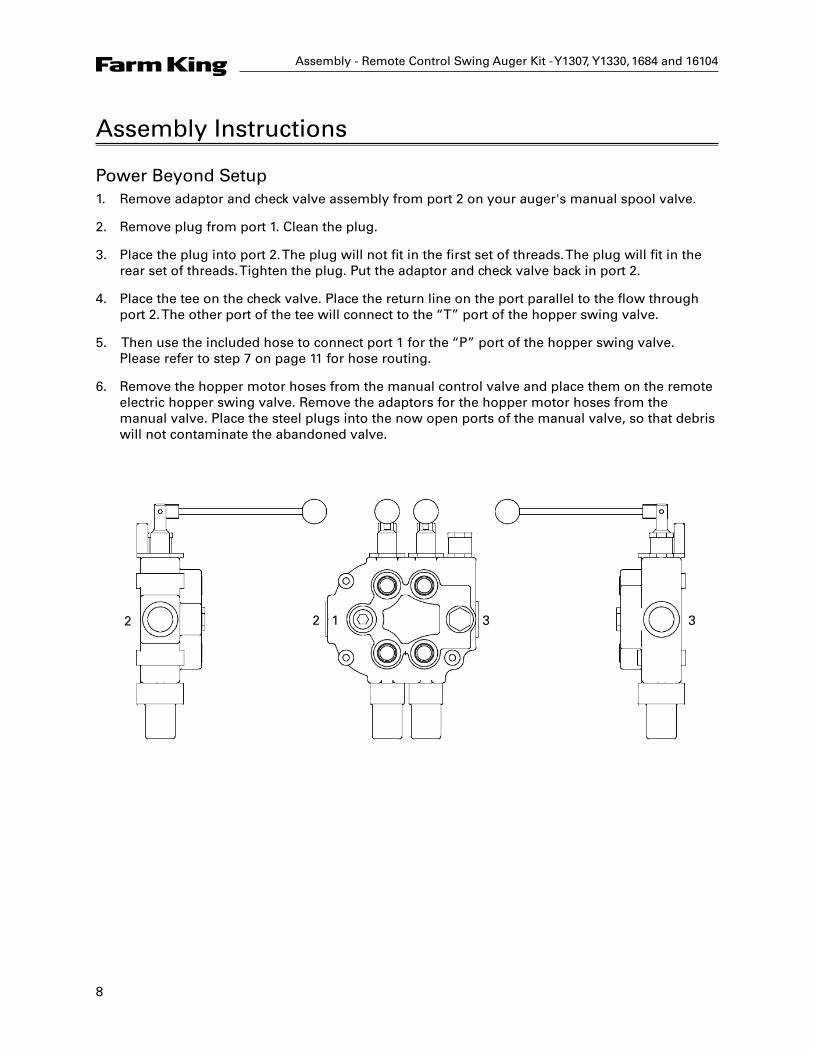
Power Beyond Setup1. Remove adaptor and check valve assembly from port 2 on your auger's manual spool valve.
2. Remove plug from port 1. Clean the plug.
3. Place the plug into port 2. The plug will not fit in the first set of threads. The plug will fit in the rear set of threads. Tighten the plug. Put the adaptor and check valve back in port 2.
4. Place the tee on the check valve. Place the return line on the port parallel to the flow through port 2. The other port of the tee will connect to the “T” port of the hopper swing valve.
5. Then use the included hose to connect port 1 for the “P” port of the hopper swing valve. Please refer to step 7 on page 11 for hose routing.
6. Remove the hopper motor hoses from the manual control valve and place them on the remote electric hopper swing valve. Remove the adaptors for the hopper motor hoses from the manual valve. Place the steel plugs into the now open ports of the manual valve, so that debris will not contaminate the abandoned valve.
Assembly - Remote Control Swing Auger Kit - Y1307, Y1330, 1684 and 16104
2 2 1 3 3
9
Assembly - Remote Control Swing Auger Kit - Y1307, Y1330, 1684 and 16104
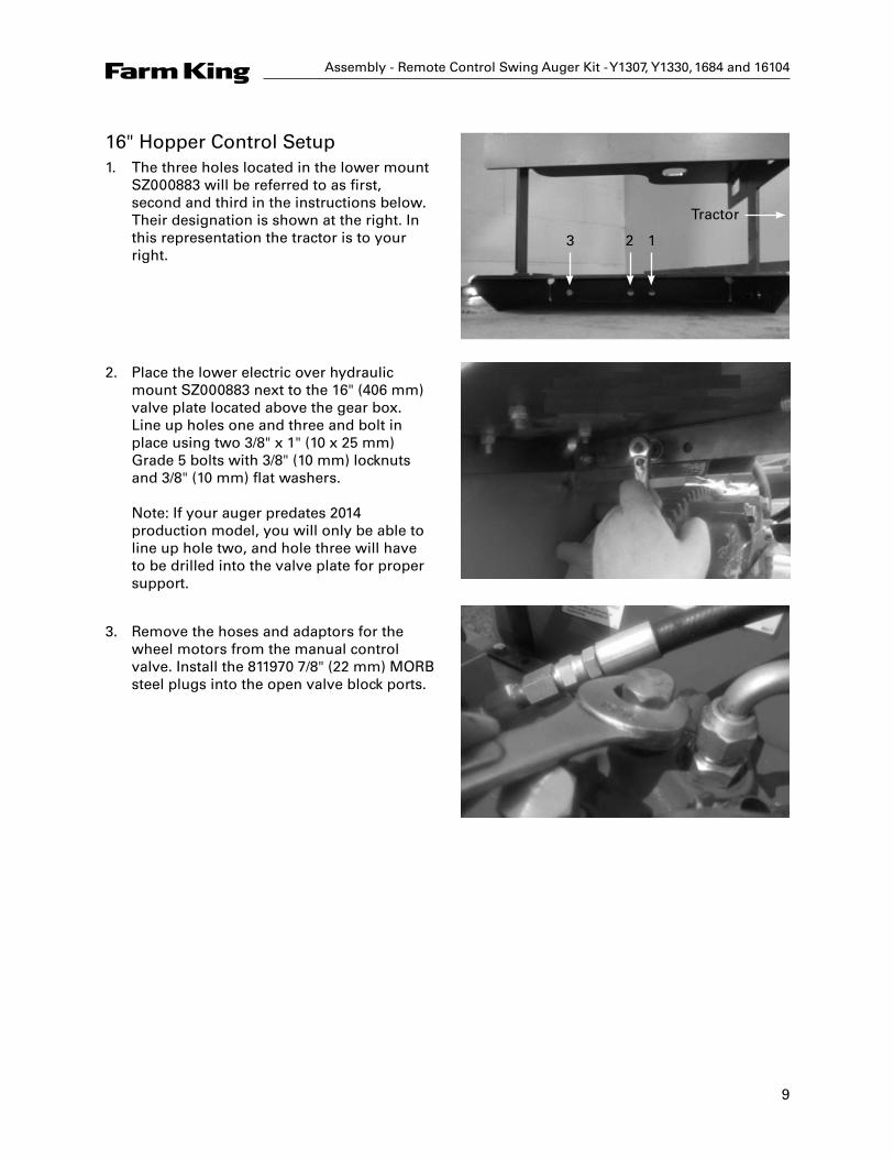
16" Hopper Control Setup1. The three holes located in the lower mount
SZ000883 will be referred to as first, second and third in the instructions below. Their designation is shown at the right. In this representation the tractor is to your right.
3 2 1
Tractor
2. Place the lower electric over hydraulic mount SZ000883 next to the 16" (406 mm) valve plate located above the gear box. Line up holes one and three and bolt in place using two 3/8" x 1" (10 x 25 mm) grade 5 bolts with 3/8" (10 mm) locknuts and 3/8" (10 mm) flat washers. Note: If your auger predates 2014 production model, you will only be able to line up hole two, and hole three will have to be drilled into the valve plate for proper support.
3. Remove the hoses and adaptors for the wheel motors from the manual control valve. Install the 811970 7/8" (22 mm) MORB steel plugs into the open valve block ports.
10
Assembly - Remote Control Swing Auger Kit - Y1307, Y1330, 1684 and 16104
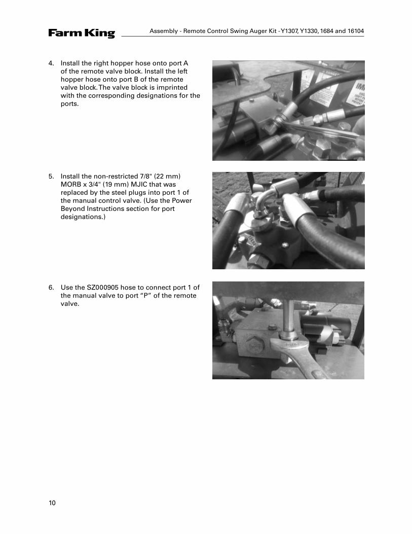
4. Install the right hopper hose onto port A of the remote valve block. Install the left hopper hose onto port B of the remote valve block. The valve block is imprinted with the corresponding designations for the ports.
5. Install the non-restricted 7/8" (22 mm) MORB x 3/4" (19 mm) MJIC that was replaced by the steel plugs into port 1 of the manual control valve. (Use the Power Beyond Instructions section for port designations.)
6. Use the SZ000905 hose to connect port 1 of the manual valve to port “P” of the remote valve.
11
Assembly - Remote Control Swing Auger Kit - Y1307, Y1330, 1684 and 16104
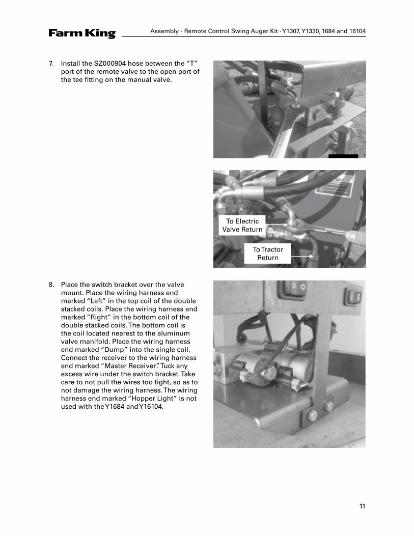
7. Install the SZ000904 hose between the “T” port of the remote valve to the open port of the tee fitting on the manual valve.
8. Place the switch bracket over the valve mount. Place the wiring harness end marked “Left” in the top coil of the double stacked coils. Place the wiring harness end marked “Right” in the bottom coil of the double stacked coils. The bottom coil is the coil located nearest to the aluminum valve manifold. Place the wiring harness end marked “Dump” into the single coil. Connect the receiver to the wiring harness end marked “Master Receiver”. Tuck any excess wire under the switch bracket. Take care to not pull the wires too tight, so as to not damage the wiring harness. The wiring harness end marked “Hopper Light” is not used with the Y1684 and Y16104.
To Electric Valve Return
To Tractor Return
12
Assembly - Remote Control Swing Auger Kit - Y1307, Y1330, 1684 and 16104
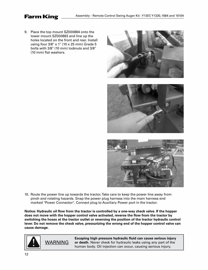
9. Place the top mount SZ000884 onto the lower mount SZ000883 and line up the holes located on the front and rear. Install using four 3/8" x 1" (10 x 25 mm) grade 5 bolts with 3/8" (10 mm) locknuts and 3/8" (10 mm) flat washers.
WARNINgEscaping high pressure hydraulic fluid can cause serious injury or death. Never check for hydraulic leaks using any part of the human body. Oil injection can occur, causing serious injury.
Notice: Hydraulic oil flow from the tractor is controlled by a one-way check valve. If the hopper does not move with the hopper control valve activated, reverse the flow from the tractor by switching the hoses at the tractor outlet or reversing the position of the tractor hydraulic control lever. Do not remove the check valve, pressurizing the wrong end of the hopper control valve can cause damage.
10. Route the power line up towards the tractor. Take care to keep the power line away from pinch and rotating hazards. Snap the power plug harness into the main harness end marked "Power Connector". Connect plug to Auxiliary Power port in the tractor.
13
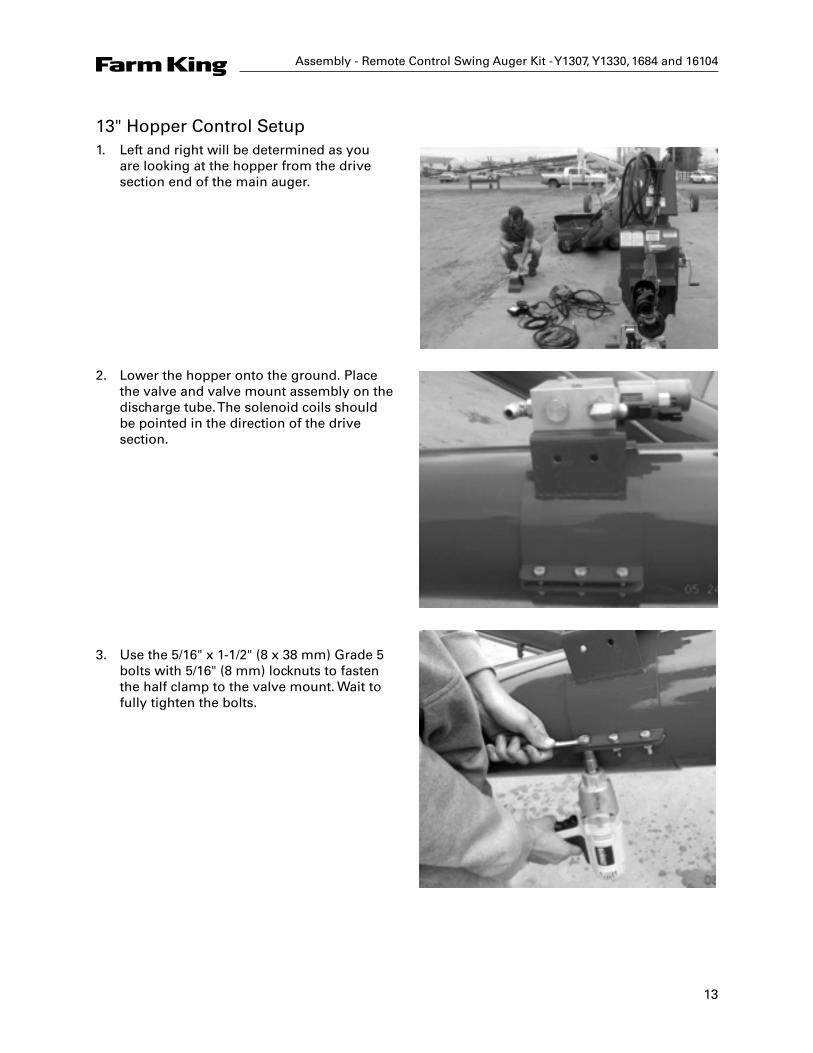
1. Left and right will be determined as you are looking at the hopper from the drive section end of the main auger.
2. Lower the hopper onto the ground. Place the valve and valve mount assembly on the discharge tube. The solenoid coils should be pointed in the direction of the drive section.
3. Use the 5/16" x 1-1/2" (8 x 38 mm) grade 5 bolts with 5/16" (8 mm) locknuts to fasten the half clamp to the valve mount. Wait to fully tighten the bolts.
Assembly - Remote Control Swing Auger Kit - Y1307, Y1330, 1684 and 16104
13" Hopper Control Setup
14
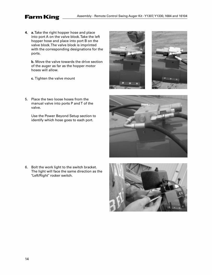
4. a. Take the right hopper hose and place into port A on the valve block. Take the left hopper hose and place into port B on the valve block. The valve block is imprinted with the corresponding designations for the ports. b. Move the valve towards the drive section of the auger as far as the hopper motor hoses will allow. c. Tighten the valve mount
5. Place the two loose hoses from the manual valve into ports P and T of the valve. Use the Power Beyond Setup section to identify which hose goes to each port.
6. Bolt the work light to the switch bracket. The light will face the same direction as the “Left/Right” rocker switch.
Assembly - Remote Control Swing Auger Kit - Y1307, Y1330, 1684 and 16104
15
WARNINgEscaping high pressure hydraulic fluid can cause serious injury or death. Never check for hydraulic leaks using any part of the human body. Oil injection can occur, causing serious injury.
Notice: Hydraulic oil flow from the tractor is controlled by a one-way check valve. If the hopper does not move with the hopper control valve activated, reverse the flow from the tractor by switching the hoses at the tractor outlet or reversing the position of the tractor hydraulic control lever. Do not remove the check valve, pressurizing the wrong end of the hopper control valve can cause damage.
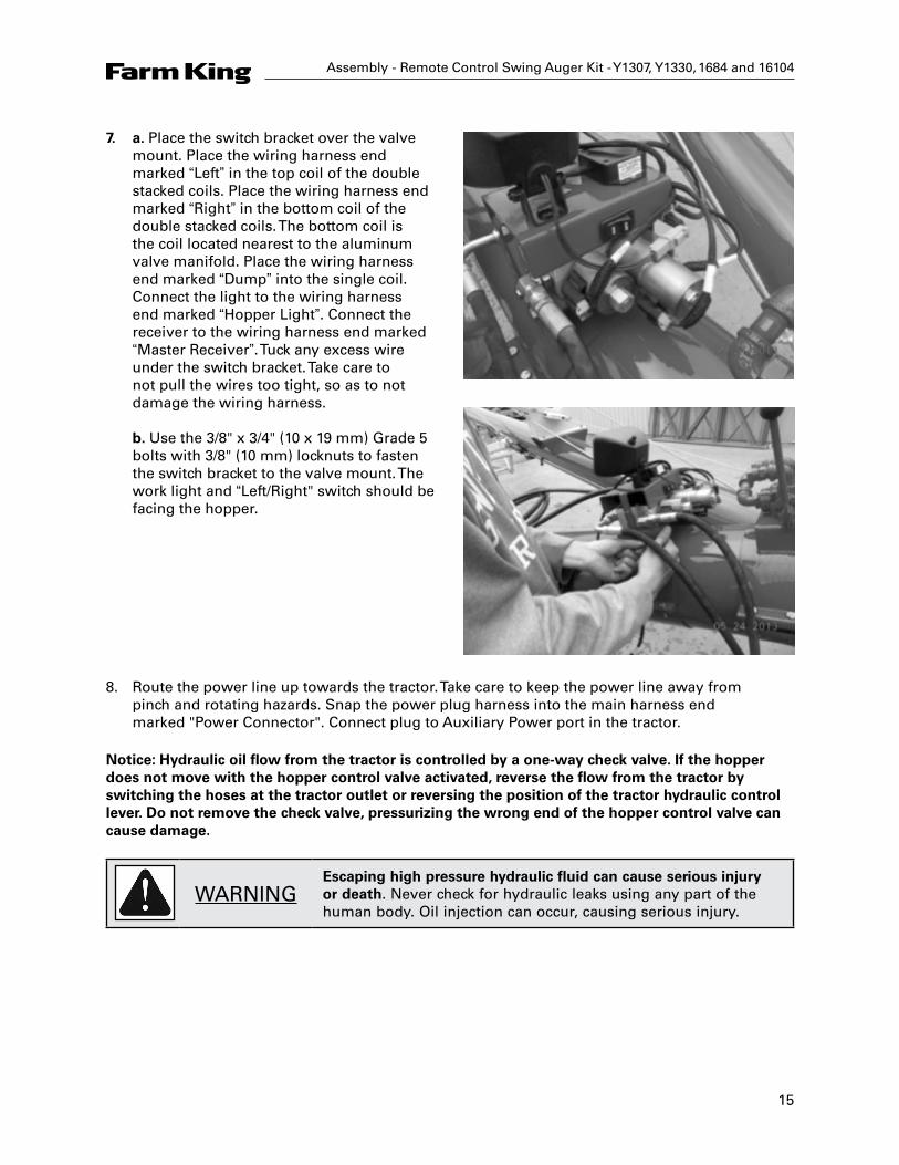
7. a. Place the switch bracket over the valve mount. Place the wiring harness end marked “Left” in the top coil of the double stacked coils. Place the wiring harness end marked “Right” in the bottom coil of the double stacked coils. The bottom coil is the coil located nearest to the aluminum valve manifold. Place the wiring harness end marked “Dump” into the single coil. Connect the light to the wiring harness end marked “Hopper Light”. Connect the receiver to the wiring harness end marked “Master Receiver”. Tuck any excess wire under the switch bracket. Take care to not pull the wires too tight, so as to not damage the wiring harness. b. Use the 3/8" x 3/4" (10 x 19 mm) grade 5 bolts with 3/8" (10 mm) locknuts to fasten the switch bracket to the valve mount. The work light and “Left/Right" switch should be facing the hopper.
8. Route the power line up towards the tractor. Take care to keep the power line away from pinch and rotating hazards. Snap the power plug harness into the main harness end marked "Power Connector". Connect plug to Auxiliary Power port in the tractor.
Assembly - Remote Control Swing Auger Kit - Y1307, Y1330, 1684 and 16104
16
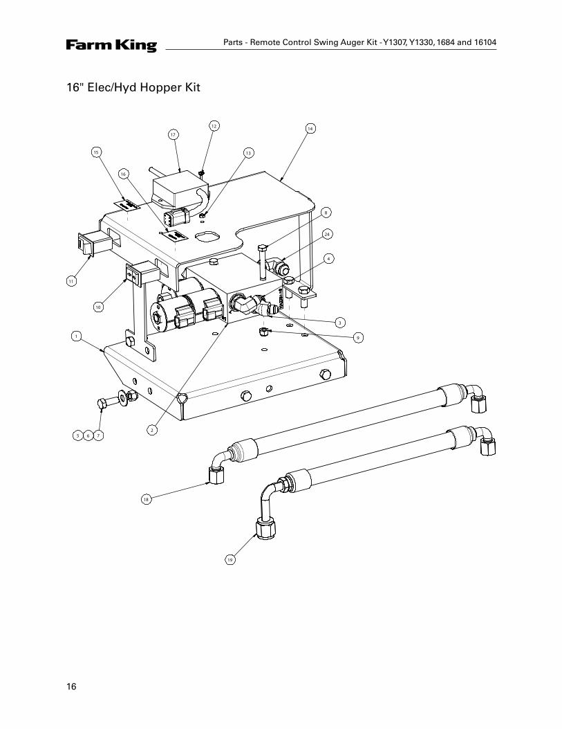
16" Elec/Hyd Hopper Kit
Parts - Remote Control Swing Auger Kit - Y1307, Y1330, 1684 and 16104
765
4
3
1
18
19
9
16
15
10
11
8
1417
12
13
24
2

17
Item Part Number Description Qty
1 SZ000883 16" Elec/Hyd Bottom Mount 1
2 SZ000789 Elec/Hyd Valve Block 1
3 SZ000790 Ftg 45 06MJ 08MB 1/32ORF 1
4 SZ000799 Ftg 90 06MJIC 08MOB 1
5 SZ127002 Wshr Flt 3/8" 6
6 SZ125030 Nut Lock 3/8-16 UNC Nylock 6
7 SZ126065 Blt HHCS 3/8-16 UNC 1" g5 6
8 SZ126056 Blt HHCS 5/16-18 UNC 2-3/4" gr2 2
9 SZ125035 Nut Lock 5/16-18 UNC Nylock 2
10 SZ000796 Left/Right Switch (Eaton SFRSXX1XRWXRXXX) 1
11 SZ000759 Open/Close Switch (Eaton SAASXX1XTFXTgXX) 1
12 813958 Screw Mach #8-32 x 0.75 Flathd 2
13 812537 Nut Lock (Nylon) 0.136 NC grB (Pl) 2
14 SZ000884 16" Elec/Hyd Top Mount 1
15 SZ000797 Decal - Tractor Hydraulic System 1
16 SZ000798 Decal - Manual Hopper Control 1
17 SZ000792 Kar-Tech Receiver Bundle 1
18 SZ000904 Hose Assy, 19" x 0.5", -08 JIC 90s 1
19 SZ000905 Hose Assy, 16-1/8" x 0.5", -08 JIC 90s 1
20 SZ000924 13" with winch/16" Elec/Hyd Instructions 1
21 SZ000783 Elec/Hyd Rmt Hppr Harness 1
22 SZ000787 Elec/Hyd Rmt Hppr Plug Pwr Harness 1
23 811970 #10 (7/8") MORB Steel Plug 2
24 SZ000781 Ftg 90 08MOB 08MJIC 2
Parts - Remote Control Swing Auger Kit - Y1307, Y1330, 1684 and 16104
18
Parts - Remote Control Swing Auger Kit - Y1307, Y1330, 1684 and 16104
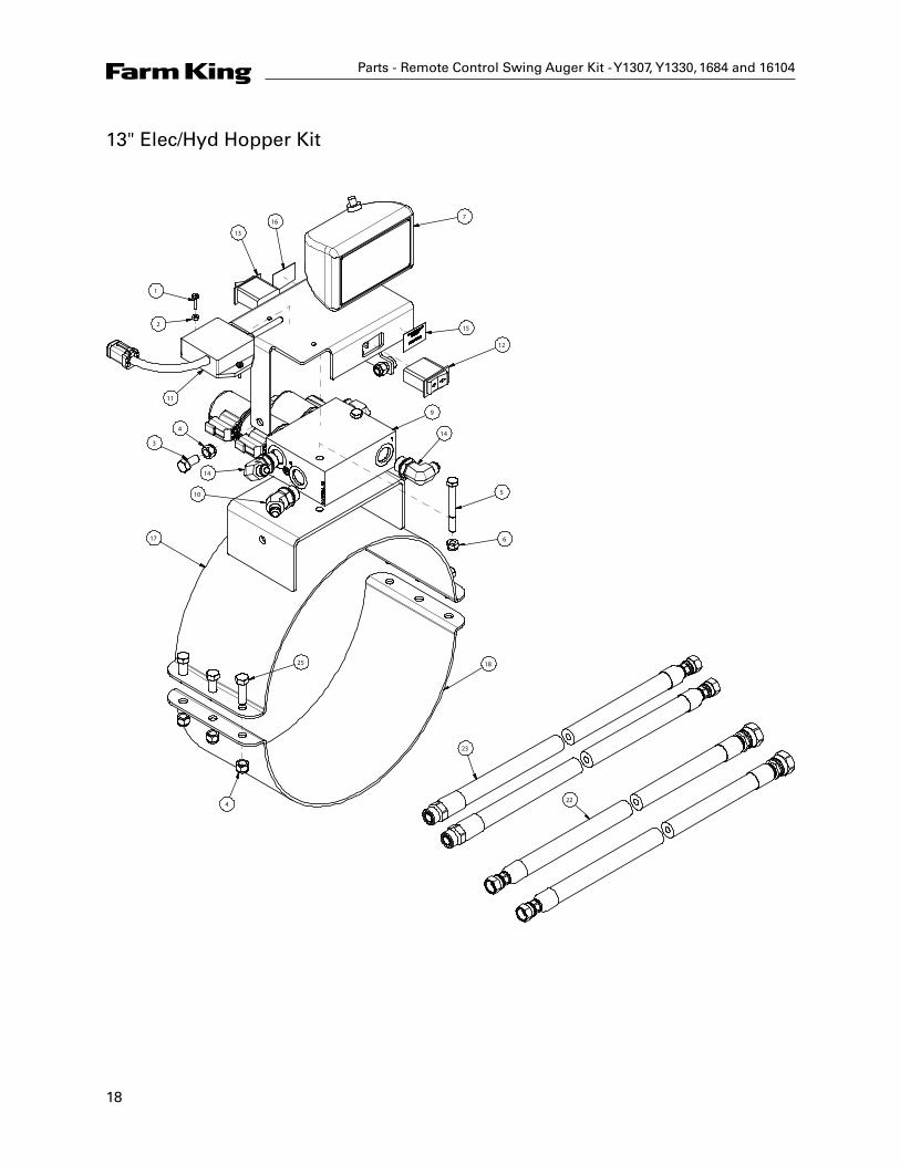
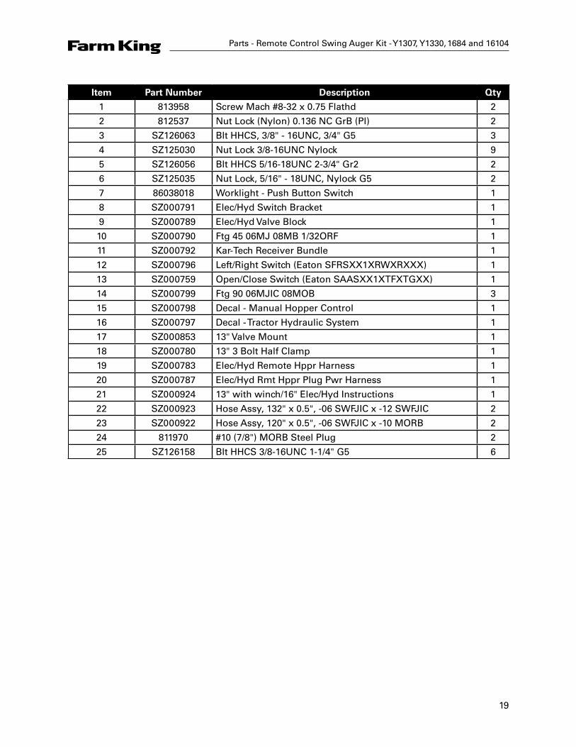
13" Elec/Hyd Hopper Kit
716
2
1
15
9
14
5
6
18
4
25
17
10
14
3
4
11
12
13
22
23
19
Parts - Remote Control Swing Auger Kit - Y1307, Y1330, 1684 and 16104
Item Part Number Description Qty
1 813958 Screw Mach #8-32 x 0.75 Flathd 2
2 812537 Nut Lock (Nylon) 0.136 NC grB (Pl) 2
3 SZ126063 Blt HHCS, 3/8" - 16UNC, 3/4" g5 3
4 SZ125030 Nut Lock 3/8-16UNC Nylock 9
5 SZ126056 Blt HHCS 5/16-18UNC 2-3/4" gr2 2
6 SZ125035 Nut Lock, 5/16" - 18UNC, Nylock g5 2
7 86038018 Worklight - Push Button Switch 1
8 SZ000791 Elec/Hyd Switch Bracket 1
9 SZ000789 Elec/Hyd Valve Block 1
10 SZ000790 Ftg 45 06MJ 08MB 1/32ORF 1
11 SZ000792 Kar-Tech Receiver Bundle 1
12 SZ000796 Left/Right Switch (Eaton SFRSXX1XRWXRXXX) 1
13 SZ000759 Open/Close Switch (Eaton SAASXX1XTFXTgXX) 1
14 SZ000799 Ftg 90 06MJIC 08MOB 3
15 SZ000798 Decal - Manual Hopper Control 1
16 SZ000797 Decal - Tractor Hydraulic System 1
17 SZ000853 13" Valve Mount 1
18 SZ000780 13" 3 Bolt Half Clamp 1
19 SZ000783 Elec/Hyd Remote Hppr Harness 1
20 SZ000787 Elec/Hyd Rmt Hppr Plug Pwr Harness 1
21 SZ000924 13" with winch/16" Elec/Hyd Instructions 1
22 SZ000923 Hose Assy, 132" x 0.5", -06 SWFJIC x -12 SWFJIC 2
23 SZ000922 Hose Assy, 120" x 0.5", -06 SWFJIC x -10 MORB 2
24 811970 #10 (7/8") MORB Steel Plug 2
25 SZ126158 Blt HHCS 3/8-16UNC 1-1/4" g5 6
20
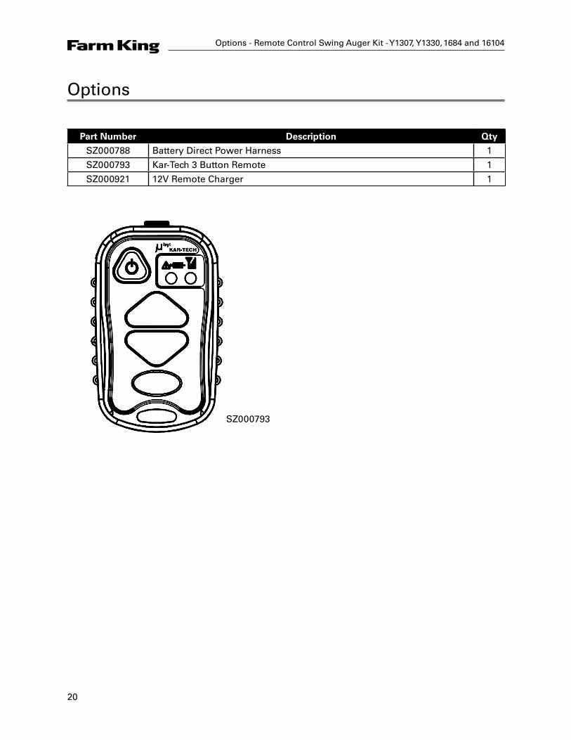
Options
Part Number Description Qty
SZ000788 Battery Direct Power Harness 1
SZ000793 Kar-Tech 3 Button Remote 1
SZ000921 12V Remote Charger 1
SZ000793
Options - Remote Control Swing Auger Kit - Y1307, Y1330, 1684 and 16104


www.farm-king.com
1330 43rd Street NWFargo, ND USA 58102Ph.: 701.282.7014 | Fax: 701.282.5865Toll Free: 888.524.1004E-mail: [email protected]
Equipment shown is subject to change without notice. ©2013 Buhler Trading Inc. Printed in USA. TSX:BUI
a division of Buhler Industries Inc.


