Operator and parts manual - 2013 OPERATOR AND PARTS MANUAL These systems are packaged to include one or several label heads as well as a conveyor and may contain several options such as status light tower, transparent label detectors, etc. Some of the options described in this manual may not apply to your equipment. HMI Password: 12345678 Adv. Settings: 222183600
Transcript
Operator and parts manual - 2013
OPERATOR AND PARTS MANUAL These systems are packaged to include one or several label heads as well as a conveyor and may contain several options such as status light tower,
transparent label detectors, etc.
Some of the options described in this manual may not apply to your equipment.
4.4 Lance top ....................................................................................................................................................... 8
4.6 Shellshock with servo closer 360 ................................................................................................................ 10
4.7 This equipment is an assembly of 3 major components ............................................................................. 11
4.8 Direction of travel ....................................................................................................................................... 11
6 SYSTEM SETUP ..................................................................................................................................................14
6.1 MAIN CONTROL PANEL with HMI Touch Screen ......................................................................................... 14
Loading & unloading the label stock roll ............................................................................. 15 Connectivity and labeler head manual feed control button ............................................... 19 Setting the Label GAP sensor ............................................................................................... 20
Standard GAP sensor – for Opaque labels Tritronic model # LER ........................ 20
GAP sensor for transparent label Tritronic Model # CLS ..................................................... 21 GAP sensor for transparent label SICK Model # UF3 ............................................ 21
GAP Sensor calibration - Quick procedure – SICK Model UF3 .............................. 23
GAP sensor calibration - CLEAR label - Quick procedure Di-Soric Model # KSSTI 1000 (Capacitive - Black) ............................................................................................................... 23
Filtering the Gap sensor trigger ........................................................................................... 24 Product sensors ................................................................................................................... 25 Labeling head POSITIONING adjustments and rulers .......................................................... 26
6.3 Side guide rails............................................................................................................................................. 30
6.4 Top retaining guides (skis) ........................................................................................................................... 30
7.2 Main screen ................................................................................................................................................. 43
7.3 TOP Labeler - Screen ................................................................................................................................... 44
Label flag (Tri-panel mode) .................................................................................................. 50 Label position on product (Tri-panel mode) ........................................................................ 50 Product Length (Tri-panel mode) ......................................................................................... 50 Gap sensor to peel plate (Tri-panel mode) .......................................................................... 50
7.7 Production menu screen ............................................................................................................................. 51
CONVEYOR: .................................................................................. Erreur ! Signet non défini. LABELER NODE 1: Corresponding to the Top Labeler ......................................................... 63
8 INFORMATION ..................................................................................................................................................69
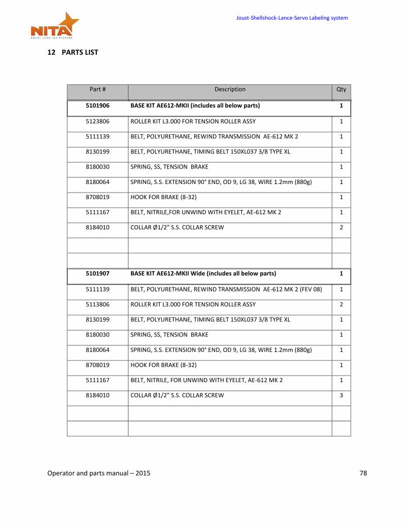
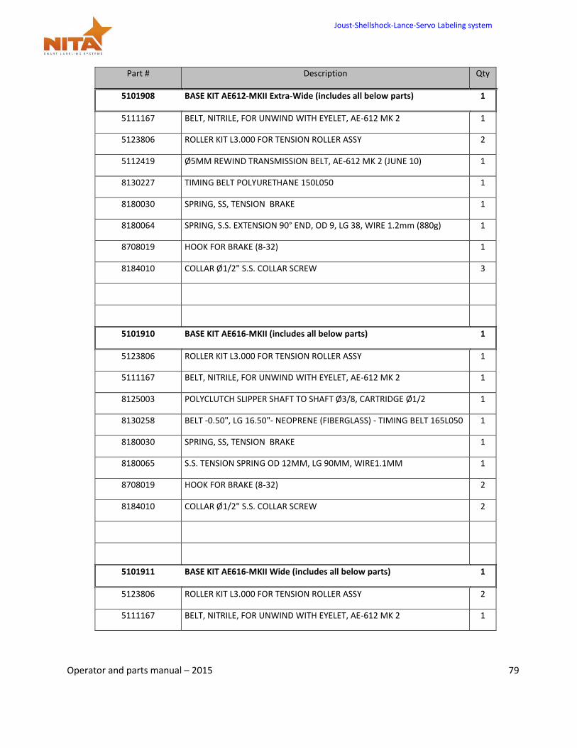
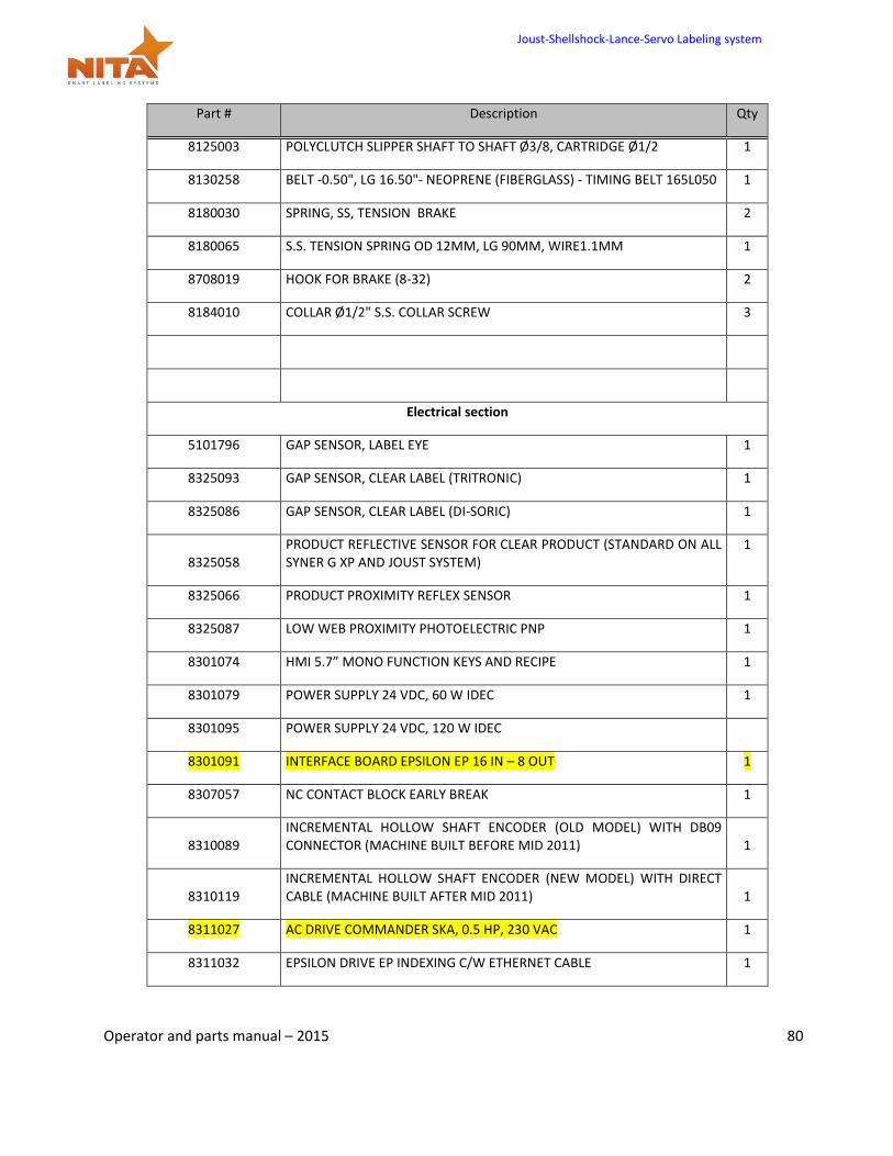
12 PARTS LIST ........................................................................................................................................................78
Thank you for choosing NITA. We have designed and manufactured this equipment with the utmost pride and care ensuring you the absolute best quality, maximum versatility and reliability.
The AE MKII labeling head guarantees constant precision and repeatability in a virtually maintenance-free operation. Being built with high grade anodized aluminum and stainless steel ensures that it provides multiple long-lasting benefits in a hostile and humid environment (please note: it is NOT considered a WASH DOWN-friendly system). Its open design, controlled by a servo motor and drive as well as an HMI touch screen operator interface, offers great flexibility suited to handling the most demanding labeling applications.
WHAT IS A LABELING SYSTEM?
Found in almost every sector of manufacturing, a labeling system is used to apply pressure sensitive labels onto boxes, cartons and plastic and glass containers. A labeling system is generally a stand-alone machine and does not require the use of a computer or label software program in order to perform its operations. It is typically built to automatically dispense one label at a time. Using a variety of different media roll widths the NITA system can run to the maximum dispensing speed of 1570 inches / minute and conveying speed of 130 feet/minute. Depending on the application the system will typically receive a signal from a product sensor to allow the dispensing of a label onto a specific product.
This equipment is intended to be used only as described in this document. NITA Labeling Equipment Inc. cannot be held responsible for the improper use or functioning of non-described functions of this machinery. Liability for any personal injury, loss of production or revenues, or property damage occasioned by the use of this manual in effect maintenance; operation, or repair of the equipment is in no way assumed by NITA Labeling Equipment Inc. Anyone using a procedure not recommended by the end user should first completely satisfy himself/herself that personal safety and equipment integrity will not be jeopardized in the method selected.
This manual will provide operating instructions, parts listing and schematics. The information contained in this manual will help the user in his/her operations, troubleshooting and maintaining the machine in good operating conditions. Information, illustrations and specifications contained in this manual are based on the latest product information available at the time of this manual release. Nita Labeling Equipment Inc. reserves the right to alter and substitute information contained herein at any time.
It is also possible that you have received a different variation of this equipment, with several different options. Some pictures used in this manual may not totally reflect your configuration, although the labeling is completely the same.
All rights reserved
While every precaution has been taken in the preparation of this manual, Nita Labeling Equipment Inc. assumes no responsibility for errors or omissions. Neither is any liability assumed for damages, loss of production, or revenues resulting from the use of the information contained herein.
Joust-Shellshock-Lance-Servo Labeling system
Operator and parts manual – 2015 2
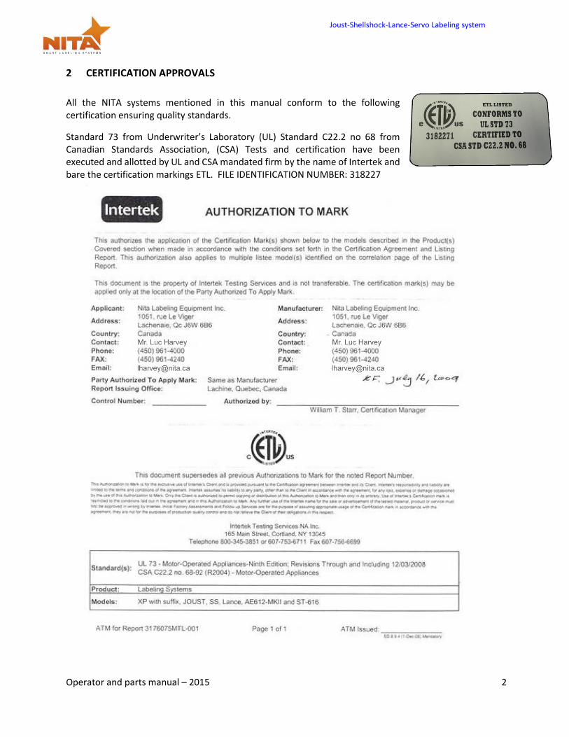
2 CERTIFICATION APPROVALS
All the NITA systems mentioned in this manual conform to the following certification ensuring quality standards.
Standard 73 from Underwriter’s Laboratory (UL) Standard C22.2 no 68 from Canadian Standards Association, (CSA) Tests and certification have been executed and allotted by UL and CSA mandated firm by the name of Intertek and bare the certification markings ETL. FILE IDENTIFICATION NUMBER: 318227
Joust-Shellshock-Lance-Servo Labeling system
Operator and parts manual – 2015 3
3 WARNINGS AND CAUTION INFORMATION
Machine use disclaimer
This equipment must NOT be used for the purposes other than for which it has been supplied to the customer under the purchase agreement and reflected in the quotation provided to the distributor or end user prior to purchase. Failure to use the equipment for the purpose described in this manual nullifies any warranty claim or injury claim that could arise as a result.
Safety
Be certain that the operators and maintenance personnel read this manual before attempting to operate perform maintenance or service to this equipment. Failure to follow these instructions could possibly result in serious personal injury, and cause damage to the equipment, or its components. Recognize safety symbols, words, and labels. Warning and Safety Instructions appearing in this manual are not meant to cover all possible conditions and situations that can occur. Common sense, caution, and care must always be exercised when installing, maintaining, servicing or operating this equipment.
The Joust / Lance / SSK are engineered to feed and apply labels on your products. In designing this device, NITA valued personal safety; however we would like to draw your attention to the following safety acknowledgments.
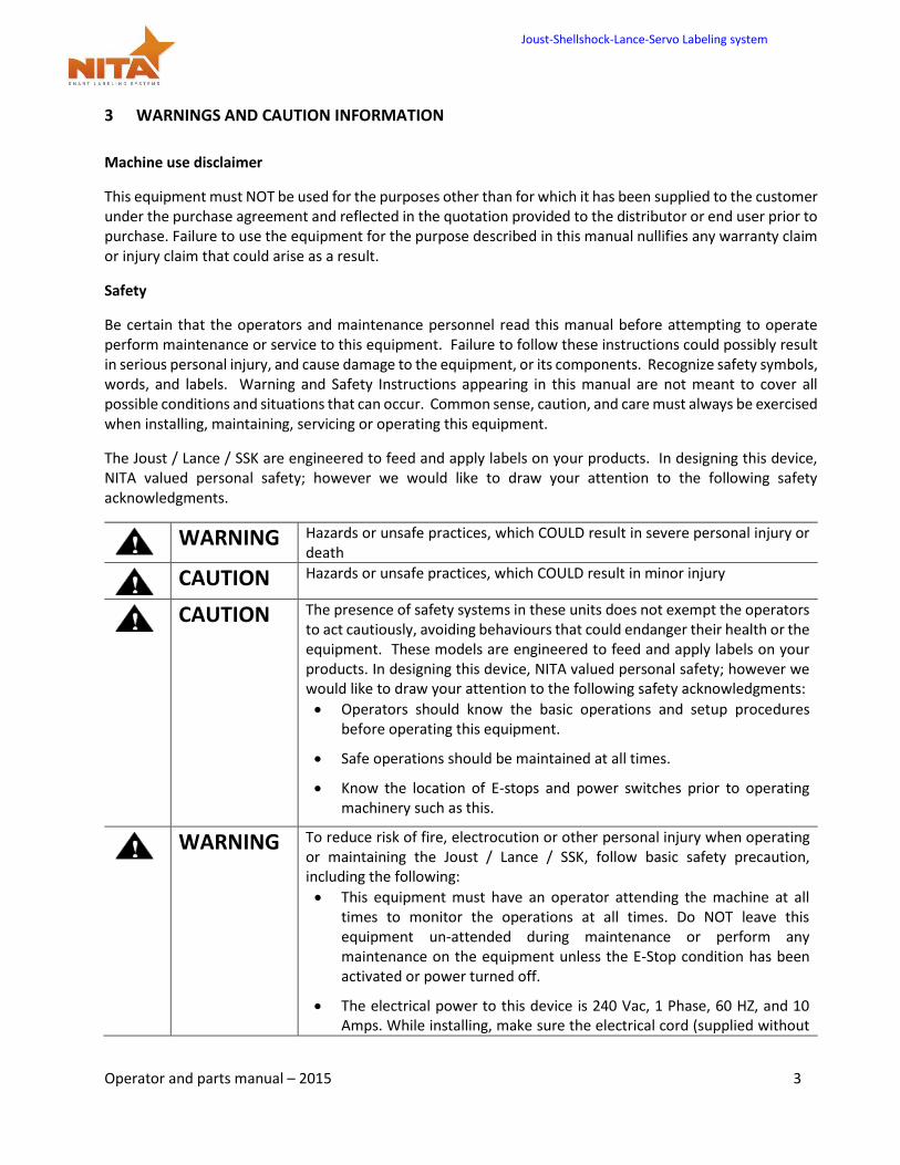
WARNING Hazards or unsafe practices, which COULD result in severe personal injury or
death
CAUTION Hazards or unsafe practices, which COULD result in minor injury
CAUTION The presence of safety systems in these units does not exempt the operators
to act cautiously, avoiding behaviours that could endanger their health or the equipment. These models are engineered to feed and apply labels on your products. In designing this device, NITA valued personal safety; however we would like to draw your attention to the following safety acknowledgments:
Operators should know the basic operations and setup procedures before operating this equipment.
Safe operations should be maintained at all times.
Know the location of E-stops and power switches prior to operating machinery such as this.
WARNING To reduce risk of fire, electrocution or other personal injury when operating
or maintaining the Joust / Lance / SSK, follow basic safety precaution, including the following:
This equipment must have an operator attending the machine at all times to monitor the operations at all times. Do NOT leave this equipment un-attended during maintenance or perform any maintenance on the equipment unless the E-Stop condition has been activated or power turned off.
The electrical power to this device is 240 Vac, 1 Phase, 60 HZ, and 10 Amps. While installing, make sure the electrical cord (supplied without
Joust-Shellshock-Lance-Servo Labeling system
Operator and parts manual – 2015 4
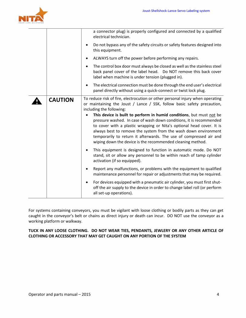
a connector plug) is properly configured and connected by a qualified electrical technician.
Do not bypass any of the safety circuits or safety features designed into this equipment.
ALWAYS turn off the power before performing any repairs.
The control box door must always be closed as well as the stainless steel back panel cover of the label head. Do NOT remove this back cover label when machine is under tension (plugged in).
The electrical connection must be done through the end user’s electrical panel directly without using a quick-connect or twist lock plug.
CAUTION To reduce risk of fire, electrocution or other personal injury when operating
or maintaining the Joust / Lance / SSK, follow basic safety precaution, including the following:
This device is built to perform in humid conditions, but must not be pressure washed. In case of wash down conditions, it is recommended to cover with a plastic wrapping or Nita’s optional head cover. It is always best to remove the system from the wash down environment temporarily to return it afterwards. The use of compressed air and wiping down the device is the recommended cleaning method.
This equipment is designed to function in automatic mode. Do NOT stand, sit or allow any personnel to be within reach of tamp cylinder activation (if so equipped).
Report any malfunctions, or problems with the equipment to qualified maintenance personnel for repair or adjustments that may be required.
For devices equipped with a pneumatic air cylinder, you must first shut-off the air supply to the device in order to change label roll (or perform all set-up operations).
For systems containing conveyors, you must be vigilant with loose clothing or bodily parts as they can get caught in the conveyor’s belt or chains as direct injury or death can incur. DO NOT use the conveyor as a working platform or walkway.
TUCK IN ANY LOOSE CLOTHING. DO NOT WEAR TIES, PENDANTS, JEWLERY OR ANY OTHER ARTICLE OF CLOTHING OR ACCESSORY THAT MAY GET CAUGHT ON ANY PORTION OF THE SYSTEM
Joust-Shellshock-Lance-Servo Labeling system
Operator and parts manual – 2015 5
4 PRODUCT INTRODUCTION
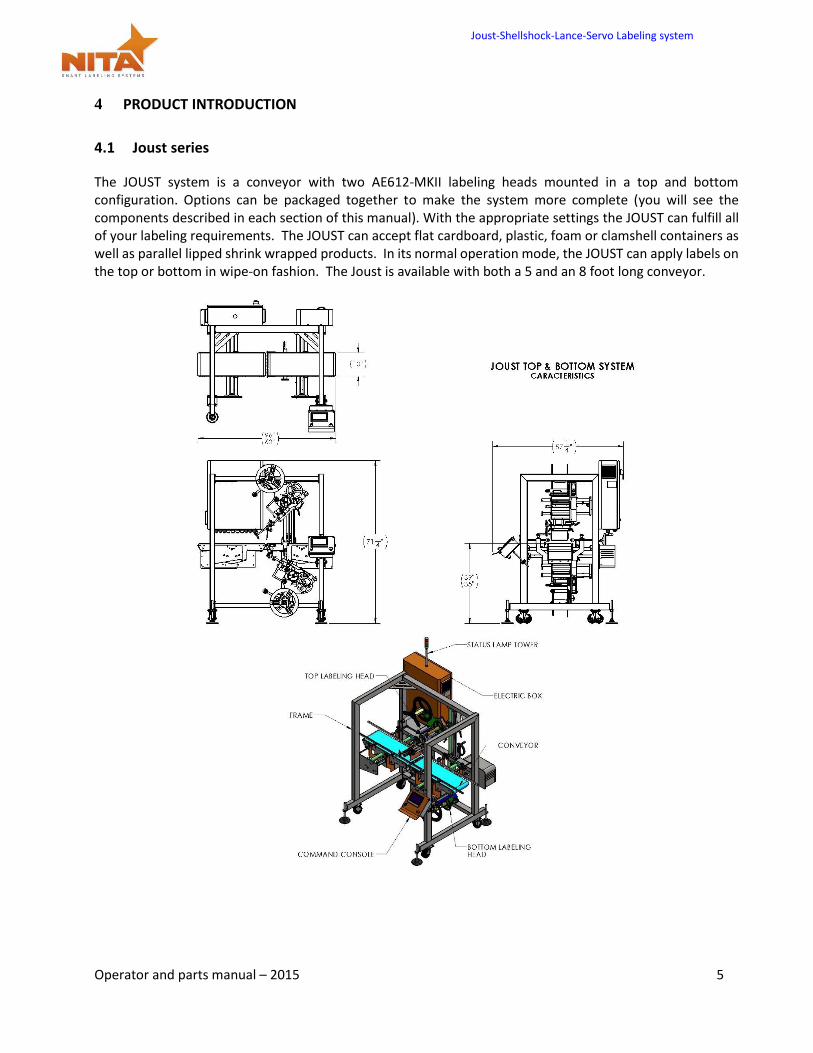
4.1 Joust series
The JOUST system is a conveyor with two AE612-MKII labeling heads mounted in a top and bottom configuration. Options can be packaged together to make the system more complete (you will see the components described in each section of this manual). With the appropriate settings the JOUST can fulfill all of your labeling requirements. The JOUST can accept flat cardboard, plastic, foam or clamshell containers as well as parallel lipped shrink wrapped products. In its normal operation mode, the JOUST can apply labels on the top or bottom in wipe-on fashion. The Joust is available with both a 5 and an 8 foot long conveyor.
Joust-Shellshock-Lance-Servo Labeling system
Operator and parts manual – 2015 6
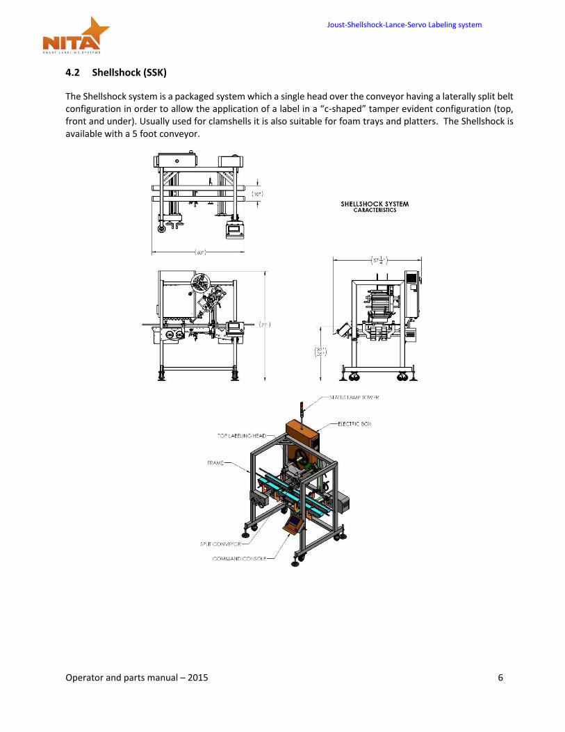
4.2 Shellshock (SSK)
The Shellshock system is a packaged system which a single head over the conveyor having a laterally split belt configuration in order to allow the application of a label in a “c-shaped” tamper evident configuration (top, front and under). Usually used for clamshells it is also suitable for foam trays and platters. The Shellshock is available with a 5 foot conveyor.
Joust-Shellshock-Lance-Servo Labeling system
Operator and parts manual – 2015 7
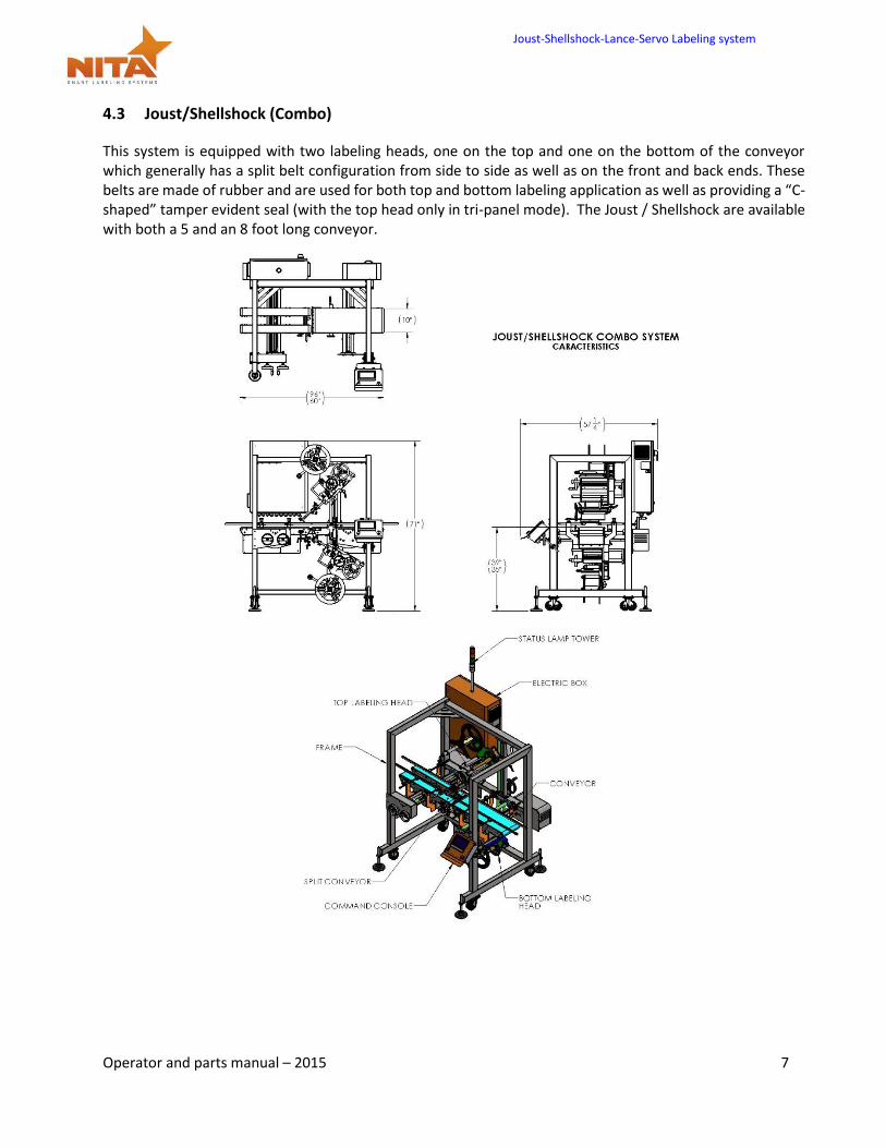
4.3 Joust/Shellshock (Combo)
This system is equipped with two labeling heads, one on the top and one on the bottom of the conveyor which generally has a split belt configuration from side to side as well as on the front and back ends. These belts are made of rubber and are used for both top and bottom labeling application as well as providing a “C-shaped” tamper evident seal (with the top head only in tri-panel mode). The Joust / Shellshock are available with both a 5 and an 8 foot long conveyor.
Joust-Shellshock-Lance-Servo Labeling system
Operator and parts manual – 2015 8
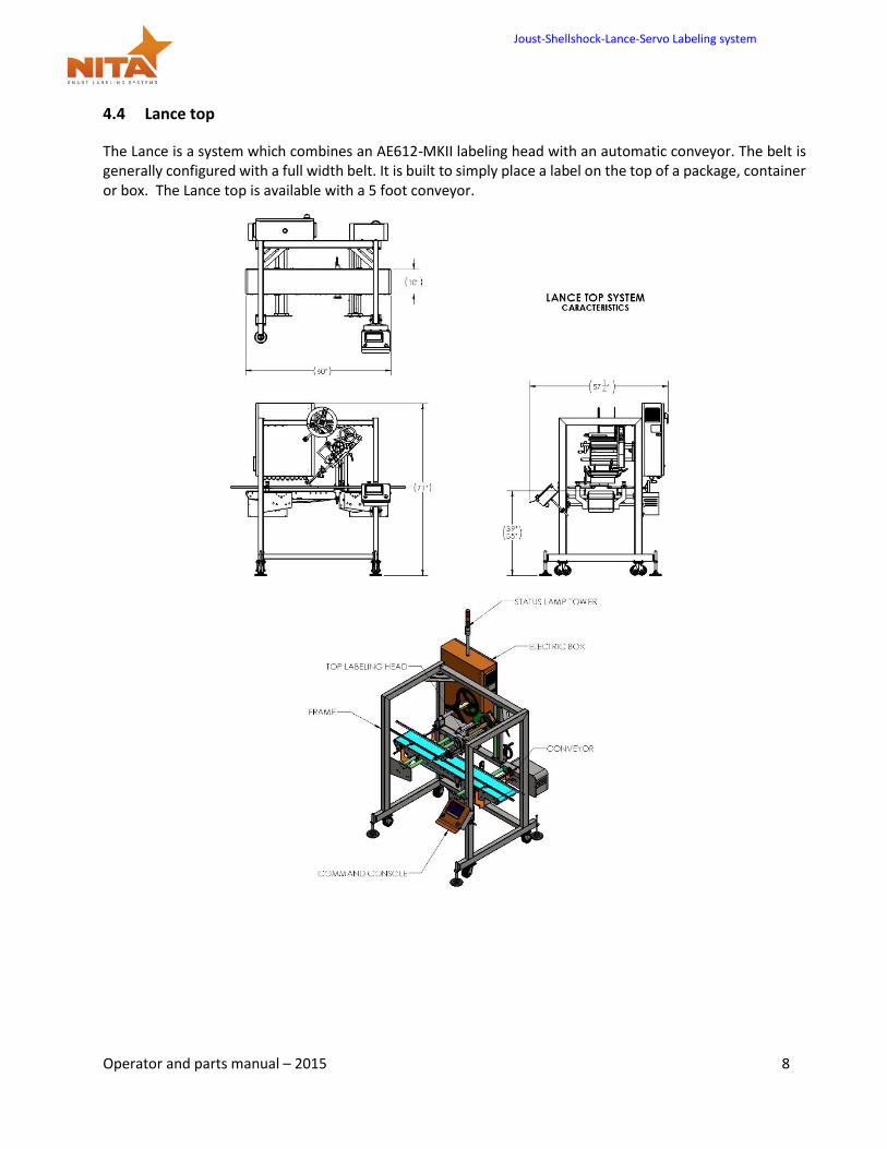
4.4 Lance top
The Lance is a system which combines an AE612-MKII labeling head with an automatic conveyor. The belt is generally configured with a full width belt. It is built to simply place a label on the top of a package, container or box. The Lance top is available with a 5 foot conveyor.
Joust-Shellshock-Lance-Servo Labeling system
Operator and parts manual – 2015 9
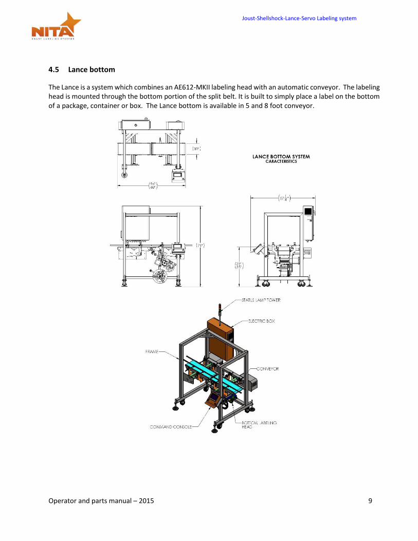
4.5 Lance bottom
The Lance is a system which combines an AE612-MKII labeling head with an automatic conveyor. The labeling head is mounted through the bottom portion of the split belt. It is built to simply place a label on the bottom of a package, container or box. The Lance bottom is available in 5 and 8 foot conveyor.
Joust-Shellshock-Lance-Servo Labeling system
Operator and parts manual – 2015 10
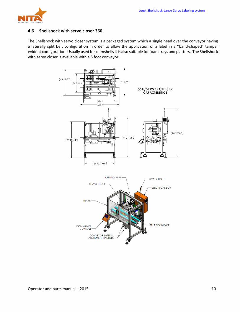
4.6 Shellshock with servo closer 360
The Shellshock with servo closer system is a packaged system which a single head over the conveyor having a laterally split belt configuration in order to allow the application of a label in a “band-shaped” tamper evident configuration. Usually used for clamshells it is also suitable for foam trays and platters. The Shellshock with servo closer is available with a 5 foot conveyor.
Joust-Shellshock-Lance-Servo Labeling system
Operator and parts manual – 2015 11
4.7 This equipment is an assembly of 3 major components
Conveyor
1 or 2 Wipe-On AE612-MKII Servo driven label applicators
HMI touch screen control panel and electrical cabinet
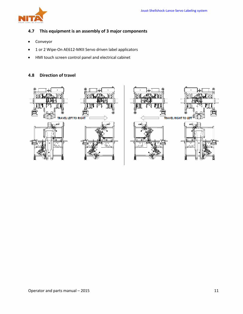
4.8 Direction of travel
Joust-Shellshock-Lance-Servo Labeling system
Operator and parts manual – 2015 12
5 SHIPMENT RECEPTION (uncrating)
For shipping purposes, a half crate is used. This avoids any damage to the device as well as protects the adjustment settings allowing for a very stable product once installed in its final destination.
The crate is generally pop-nailed together and can be taken apart by using a simple hammer or a nail crowbar. Proceed in removing the side wood panels from the crate and work your way inward.
WARNING Always be vigilant while using any tools as they can result in bodily injury.
The Joust / Lance / SSK was carefully packaged and protected prior to transportation. On reception of the machine, a complete visual inspection should be done in order to detect any apparent damage before proceeding with the equipment power up.
If any anomaly is detected, verify if the packaging/crating shows apparent damage. If it is the case, please contact the transporter right away (it is always a good idea to take pictures of the damages).
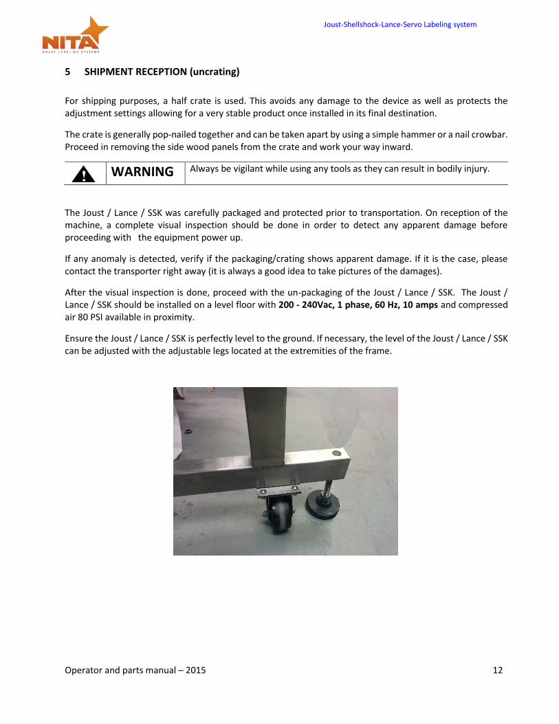
After the visual inspection is done, proceed with the un-packaging of the Joust / Lance / SSK. The Joust / Lance / SSK should be installed on a level floor with 200 - 240Vac, 1 phase, 60 Hz, 10 amps and compressed air 80 PSI available in proximity.
Ensure the Joust / Lance / SSK is perfectly level to the ground. If necessary, the level of the Joust / Lance / SSK can be adjusted with the adjustable legs located at the extremities of the frame.
Joust-Shellshock-Lance-Servo Labeling system
Operator and parts manual – 2015 13
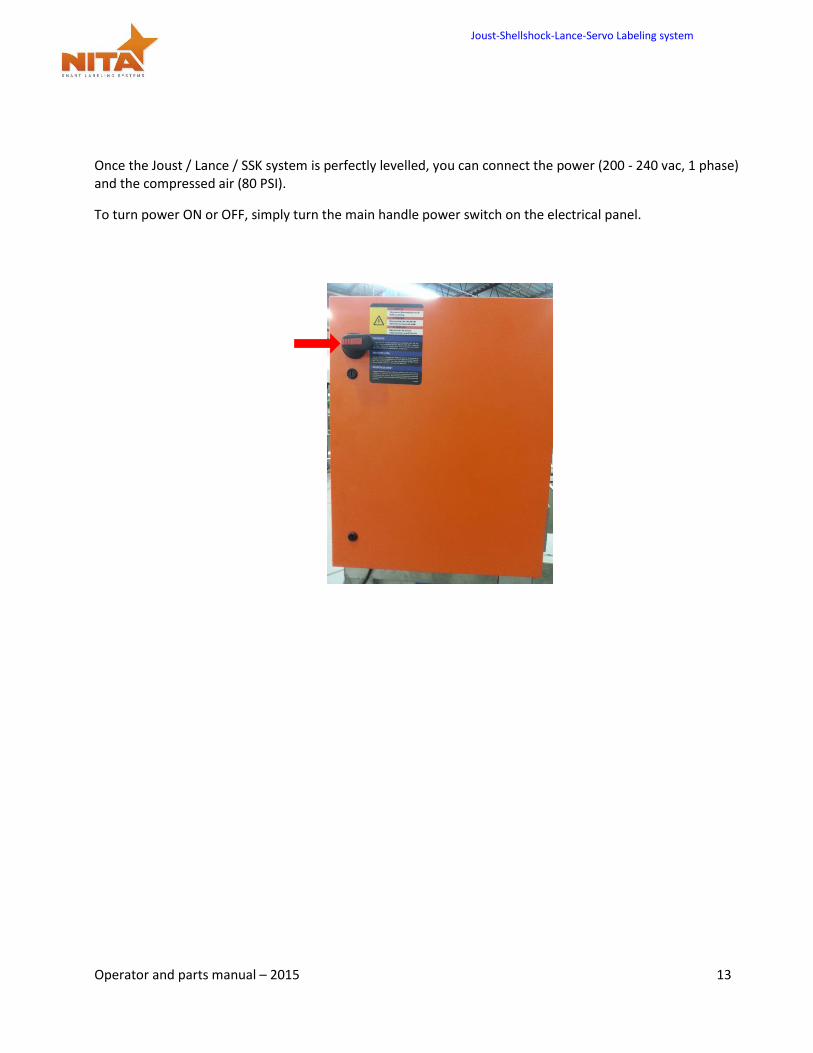
Once the Joust / Lance / SSK system is perfectly levelled, you can connect the power (200 - 240 vac, 1 phase) and the compressed air (80 PSI).
To turn power ON or OFF, simply turn the main handle power switch on the electrical panel.
Joust-Shellshock-Lance-Servo Labeling system
Operator and parts manual – 2015 14
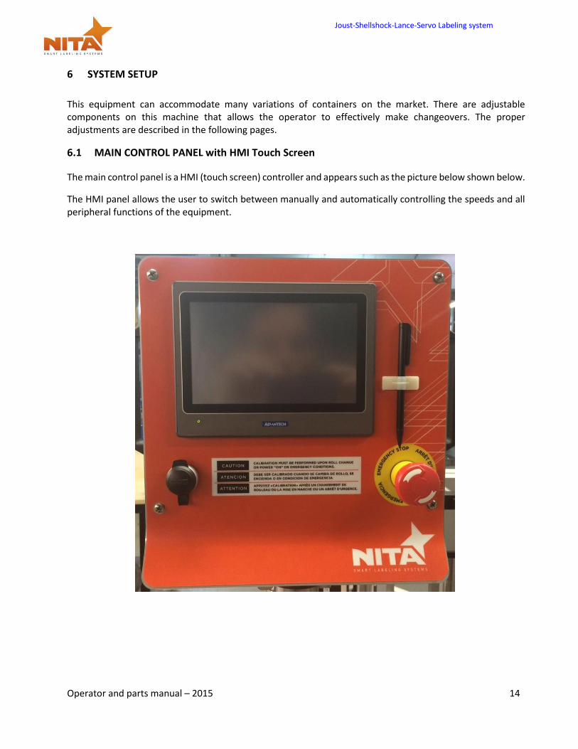
6 SYSTEM SETUP
This equipment can accommodate many variations of containers on the market. There are adjustable components on this machine that allows the operator to effectively make changeovers. The proper adjustments are described in the following pages.
6.1 MAIN CONTROL PANEL with HMI Touch Screen
The main control panel is a HMI (touch screen) controller and appears such as the picture below shown below.
The HMI panel allows the user to switch between manually and automatically controlling the speeds and all peripheral functions of the equipment.
Joust-Shellshock-Lance-Servo Labeling system
Operator and parts manual – 2015 15
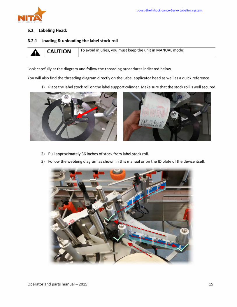
6.2 Labeling Head:
Loading & unloading the label stock roll
CAUTION To avoid injuries, you must keep the unit in MANUAL mode!
Look carefully at the diagram and follow the threading procedures indicated below.
You will also find the threading diagram directly on the Label applicator head as well as a quick reference
1) Place the label stock roll on the label support cylinder. Make sure that the stock roll is well secured
2) Pull approximately 36 inches of stock from label stock roll.
3) Follow the webbing diagram as shown in this manual or on the ID plate of the device itself.
Joust-Shellshock-Lance-Servo Labeling system
Operator and parts manual – 2015 16
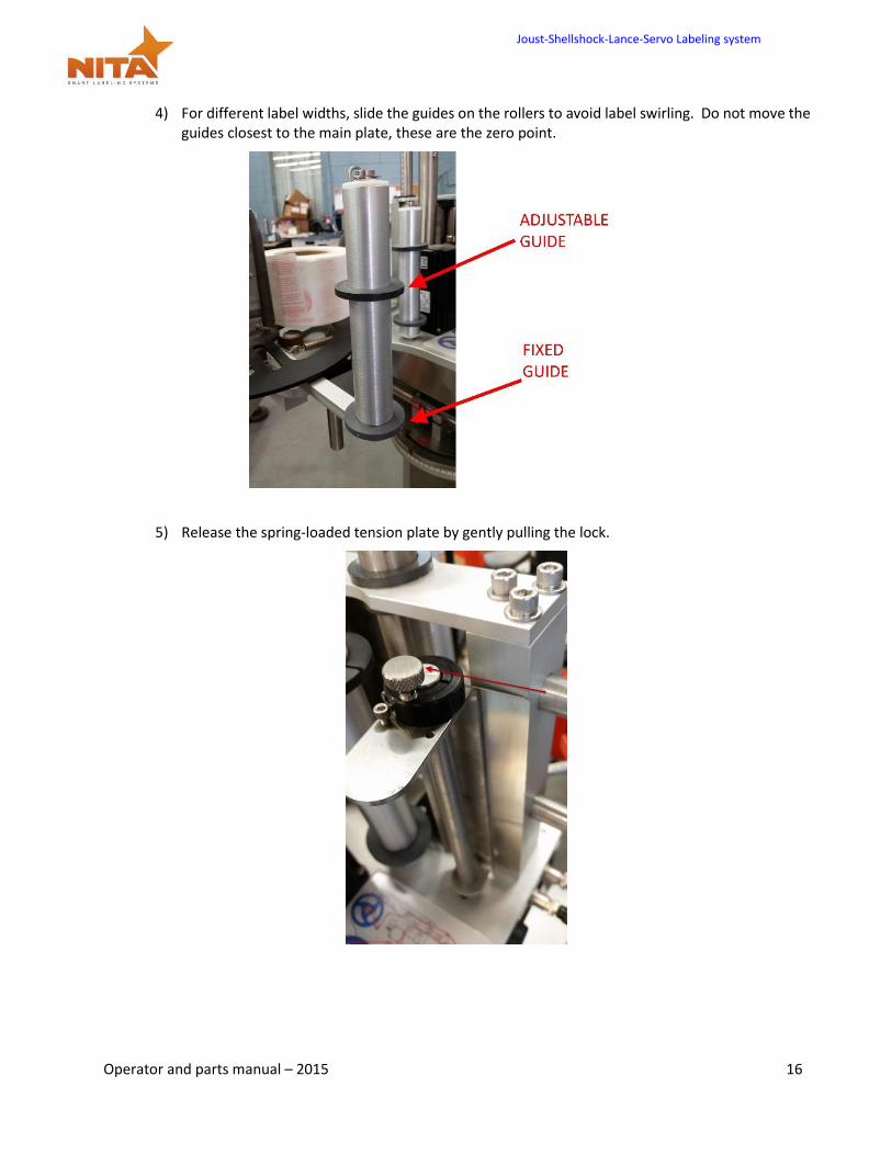
4) For different label widths, slide the guides on the rollers to avoid label swirling. Do not move the guides closest to the main plate, these are the zero point.
5) Release the spring-loaded tension plate by gently pulling the lock.
Joust-Shellshock-Lance-Servo Labeling system
Operator and parts manual – 2015 17
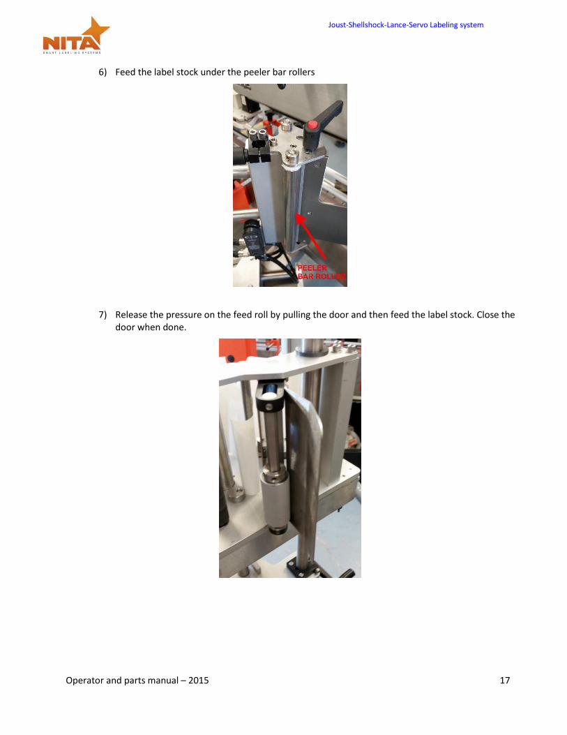
6) Feed the label stock under the peeler bar rollers
7) Release the pressure on the feed roll by pulling the door and then feed the label stock. Close the door when done.
Joust-Shellshock-Lance-Servo Labeling system
Operator and parts manual – 2015 18
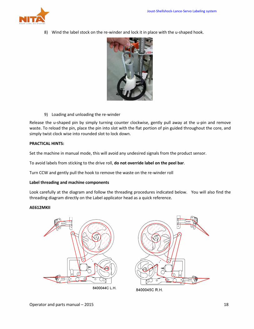
8) Wind the label stock on the re-winder and lock it in place with the u-shaped hook.
9) Loading and unloading the re-winder
Release the u-shaped pin by simply turning counter clockwise, gently pull away at the u-pin and remove waste. To reload the pin, place the pin into slot with the flat portion of pin guided throughout the core, and simply twist clock wise into rounded slot to lock down.
PRACTICAL HINTS:
Set the machine in manual mode, this will avoid any undesired signals from the product sensor.
To avoid labels from sticking to the drive roll, do not override label on the peel bar.
Turn CCW and gently pull the hook to remove the waste on the re-winder roll
Label threading and machine components
Look carefully at the diagram and follow the threading procedures indicated below. You will also find the threading diagram directly on the Label applicator head as a quick reference.
AE612MKII
Joust-Shellshock-Lance-Servo Labeling system
Operator and parts manual – 2015 19
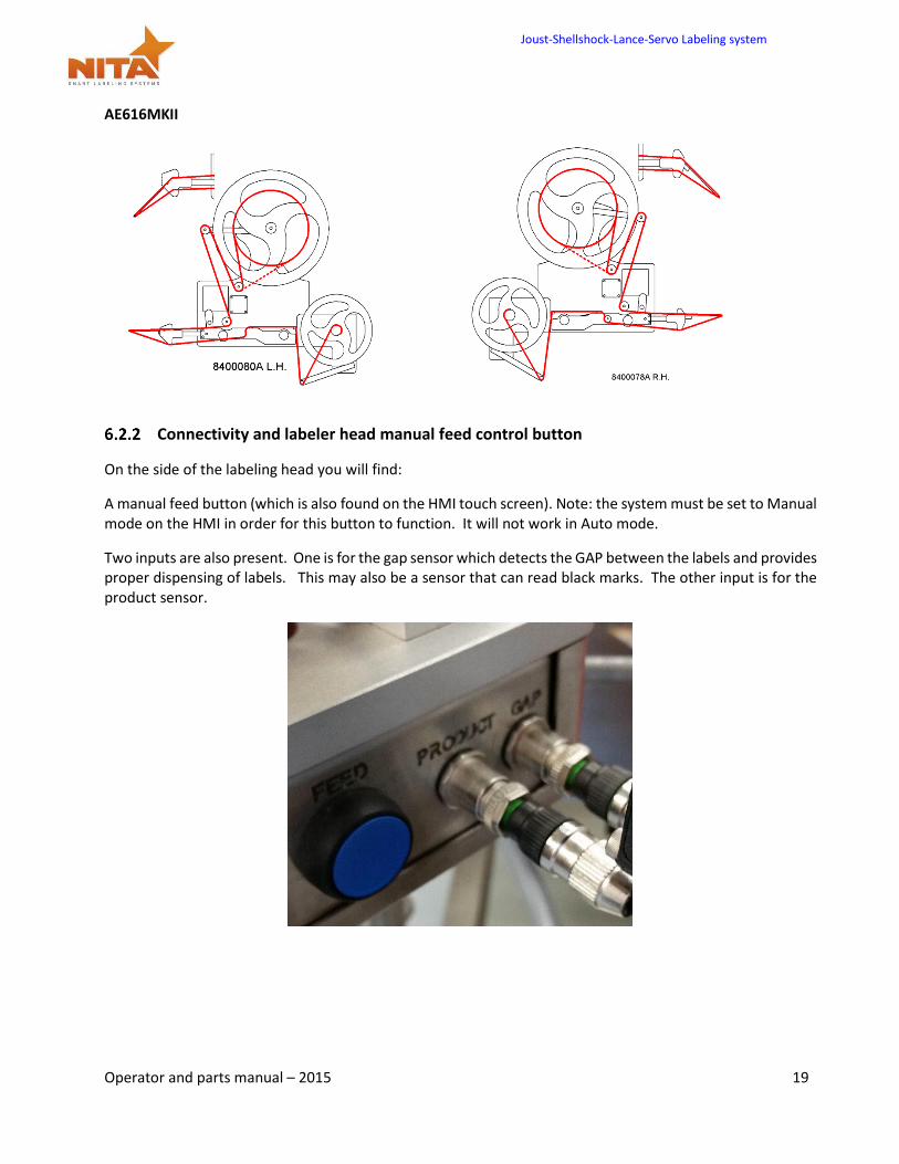
AE616MKII
Connectivity and labeler head manual feed control button
On the side of the labeling head you will find:
A manual feed button (which is also found on the HMI touch screen). Note: the system must be set to Manual mode on the HMI in order for this button to function. It will not work in Auto mode.
Two inputs are also present. One is for the gap sensor which detects the GAP between the labels and provides proper dispensing of labels. This may also be a sensor that can read black marks. The other input is for the product sensor.
Joust-Shellshock-Lance-Servo Labeling system
Operator and parts manual – 2015 20
Setting the Label GAP sensor
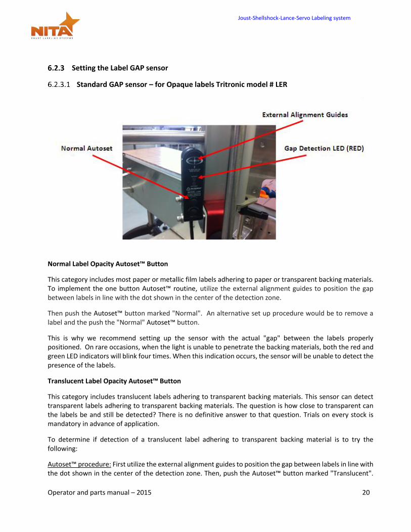
Standard GAP sensor – for Opaque labels Tritronic model # LER
Normal Label Opacity Autoset™ Button
This category includes most paper or metallic film labels adhering to paper or transparent backing materials. To implement the one button Autoset™ routine, utilize the external alignment guides to position the gap between labels in line with the dot shown in the center of the detection zone.
Then push the Autoset™ button marked "Normal". An alternative set up procedure would be to remove a label and the push the "Normal" Autoset™ button.
This is why we recommend setting up the sensor with the actual "gap" between the labels properly positioned. On rare occasions, when the light is unable to penetrate the backing materials, both the red and green LED indicators will blink four times. When this indication occurs, the sensor will be unable to detect the presence of the labels.
Translucent Label Opacity Autoset™ Button
This category includes translucent labels adhering to transparent backing materials. This sensor can detect transparent labels adhering to transparent backing materials. The question is how close to transparent can the labels be and still be detected? There is no definitive answer to that question. Trials on every stock is mandatory in advance of application.
To determine if detection of a translucent label adhering to transparent backing material is to try the following:
Autoset™ procedure: First utilize the external alignment guides to position the gap between labels in line with the dot shown in the center of the detection zone. Then, push the Autoset™ button marked "Translucent".
Joust-Shellshock-Lance-Servo Labeling system
Operator and parts manual – 2015 21
The next step is to move the web so that the translucent label goes in and out of the light beam. If detection is possible, the red LED output indicator should go on when the label passes through the detection zone.
INVERT OUTPUT: The status of the red LED and output transistors can be inverted by pressing both buttons simultaneously. When the output status has been inverted, the red LED and the output transistors will turn off when the label comes into view.
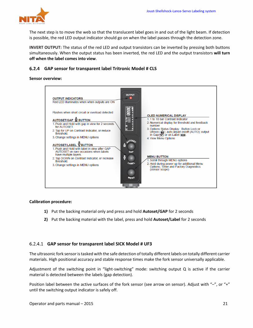
GAP sensor for transparent label Tritronic Model # CLS
Sensor overview:
Calibration procedure:
1) Put the backing material only and press and hold Autoset/GAP for 2 seconds
2) Put the backing material with the label, press and hold Autoset/Label for 2 seconds
GAP sensor for transparent label SICK Model # UF3
The ultrasonic fork sensor is tasked with the safe detection of totally different labels on totally different carrier materials. High positional accuracy and stable response times make the fork sensor universally applicable.
Adjustment of the switching point in “light-switching” mode: switching output Q is active if the carrier material is detected between the labels (gap detection).
Position label between the active surfaces of the fork sensor (see arrow on sensor). Adjust with “–”‚ or “+” until the switching output indicator is safely off.
Joust-Shellshock-Lance-Servo Labeling system
Operator and parts manual – 2015 22
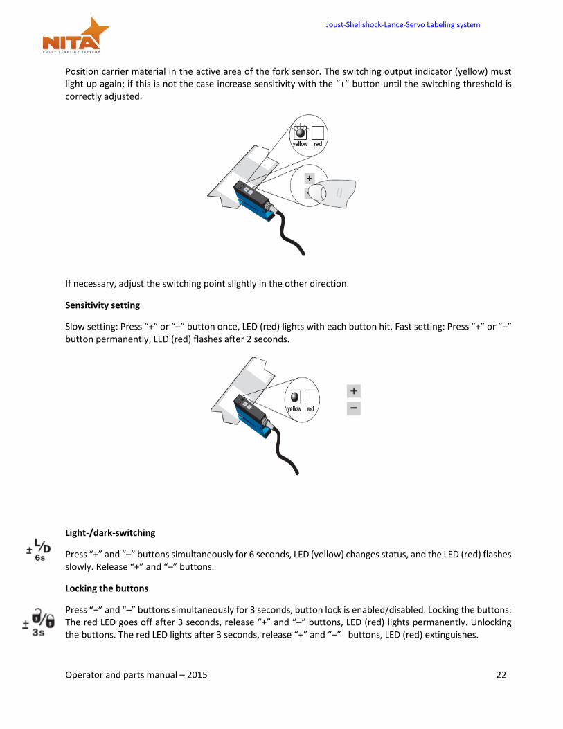
Position carrier material in the active area of the fork sensor. The switching output indicator (yellow) must light up again; if this is not the case increase sensitivity with the “+” button until the switching threshold is correctly adjusted.
If necessary, adjust the switching point slightly in the other direction.
Sensitivity setting
Slow setting: Press “+” or “–” button once, LED (red) lights with each button hit. Fast setting: Press “+” or “–” button permanently, LED (red) flashes after 2 seconds.
Light-/dark-switching
Press “+” and “–” buttons simultaneously for 6 seconds, LED (yellow) changes status, and the LED (red) flashes slowly. Release “+” and “–” buttons.
Locking the buttons
Press “+” and “–” buttons simultaneously for 3 seconds, button lock is enabled/disabled. Locking the buttons: The red LED goes off after 3 seconds, release “+” and “–” buttons, LED (red) lights permanently. Unlocking the buttons. The red LED lights after 3 seconds, release “+” and “–” buttons, LED (red) extinguishes.
Joust-Shellshock-Lance-Servo Labeling system
Operator and parts manual – 2015 23
GAP Sensor calibration - Quick procedure – SICK Model UF3
Begin by making sure that the sensor is in UN-LOCK mode. You will be able to observe a red LED on the sensor when it is locked. To unlock, press and hold both the + and -buttons simultaneously for 3 seconds. The red LED will turn off and will re-light, once it has done so, release the buttons, the red LED will remain off which will indicate the unlocked mode. Proceed with calibration.
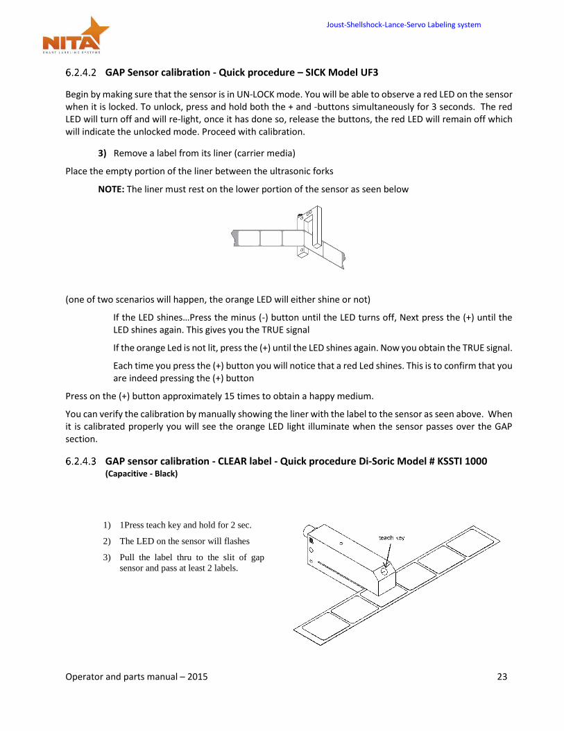
3) Remove a label from its liner (carrier media)
Place the empty portion of the liner between the ultrasonic forks
NOTE: The liner must rest on the lower portion of the sensor as seen below
(one of two scenarios will happen, the orange LED will either shine or not)
If the LED shines…Press the minus (-) button until the LED turns off, Next press the (+) until the LED shines again. This gives you the TRUE signal
If the orange Led is not lit, press the (+) until the LED shines again. Now you obtain the TRUE signal.
Each time you press the (+) button you will notice that a red Led shines. This is to confirm that you are indeed pressing the (+) button
Press on the (+) button approximately 15 times to obtain a happy medium.
You can verify the calibration by manually showing the liner with the label to the sensor as seen above. When it is calibrated properly you will see the orange LED light illuminate when the sensor passes over the GAP section.
GAP sensor calibration - CLEAR label - Quick procedure Di-Soric Model # KSSTI 1000 (Capacitive - Black)
1) 1Press teach key and hold for 2 sec.
2) The LED on the sensor will flashes
3) Pull the label thru to the slit of gap
sensor and pass at least 2 labels.
Joust-Shellshock-Lance-Servo Labeling system
Operator and parts manual – 2015 24
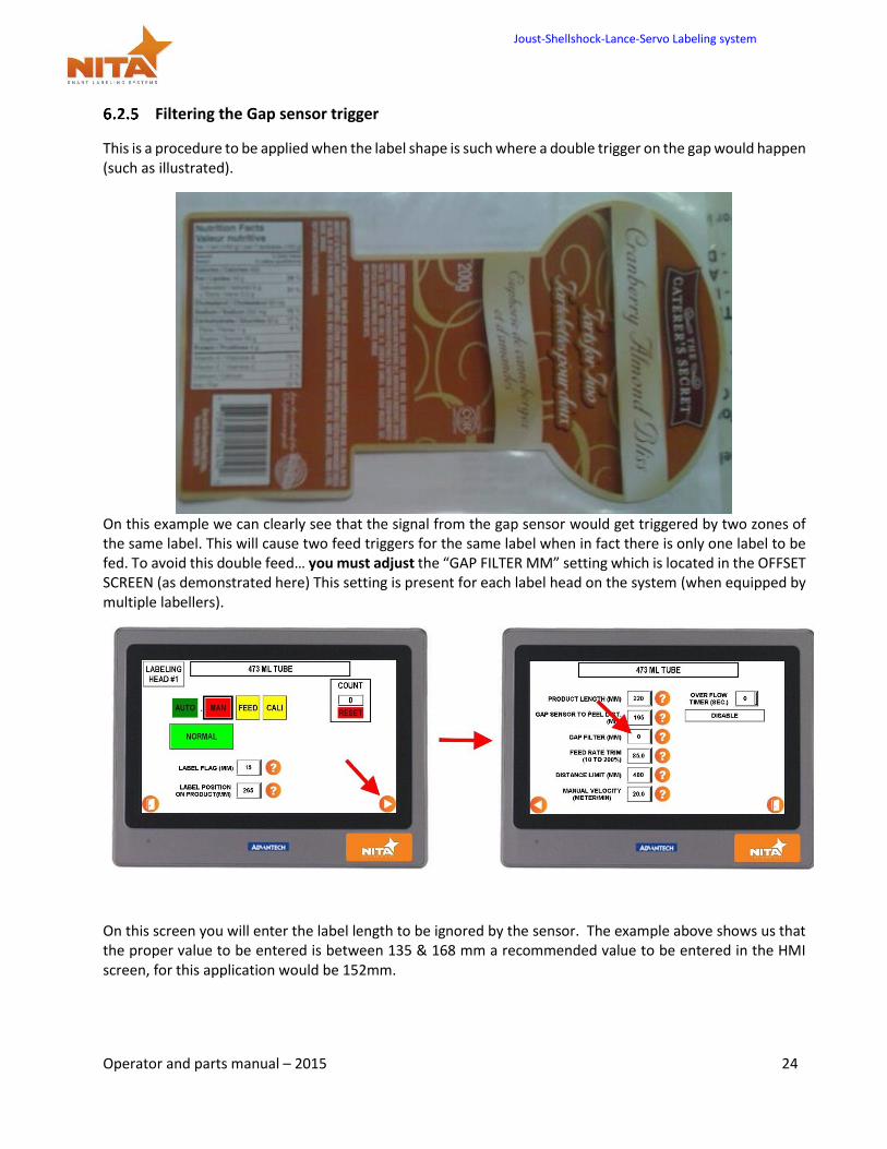
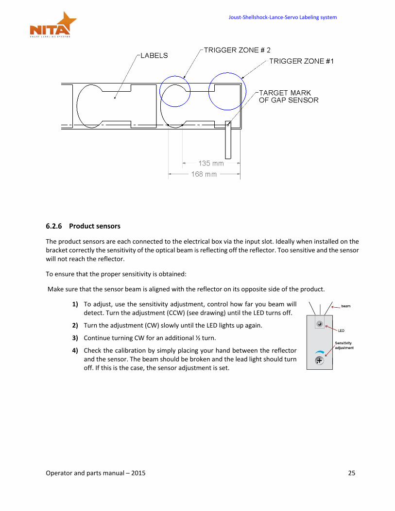
Filtering the Gap sensor trigger
This is a procedure to be applied when the label shape is such where a double trigger on the gap would happen (such as illustrated).
On this example we can clearly see that the signal from the gap sensor would get triggered by two zones of the same label. This will cause two feed triggers for the same label when in fact there is only one label to be fed. To avoid this double feed… you must adjust the “GAP FILTER MM” setting which is located in the OFFSET SCREEN (as demonstrated here) This setting is present for each label head on the system (when equipped by multiple labellers).
On this screen you will enter the label length to be ignored by the sensor. The example above shows us that the proper value to be entered is between 135 & 168 mm a recommended value to be entered in the HMI screen, for this application would be 152mm.
Joust-Shellshock-Lance-Servo Labeling system
Operator and parts manual – 2015 25
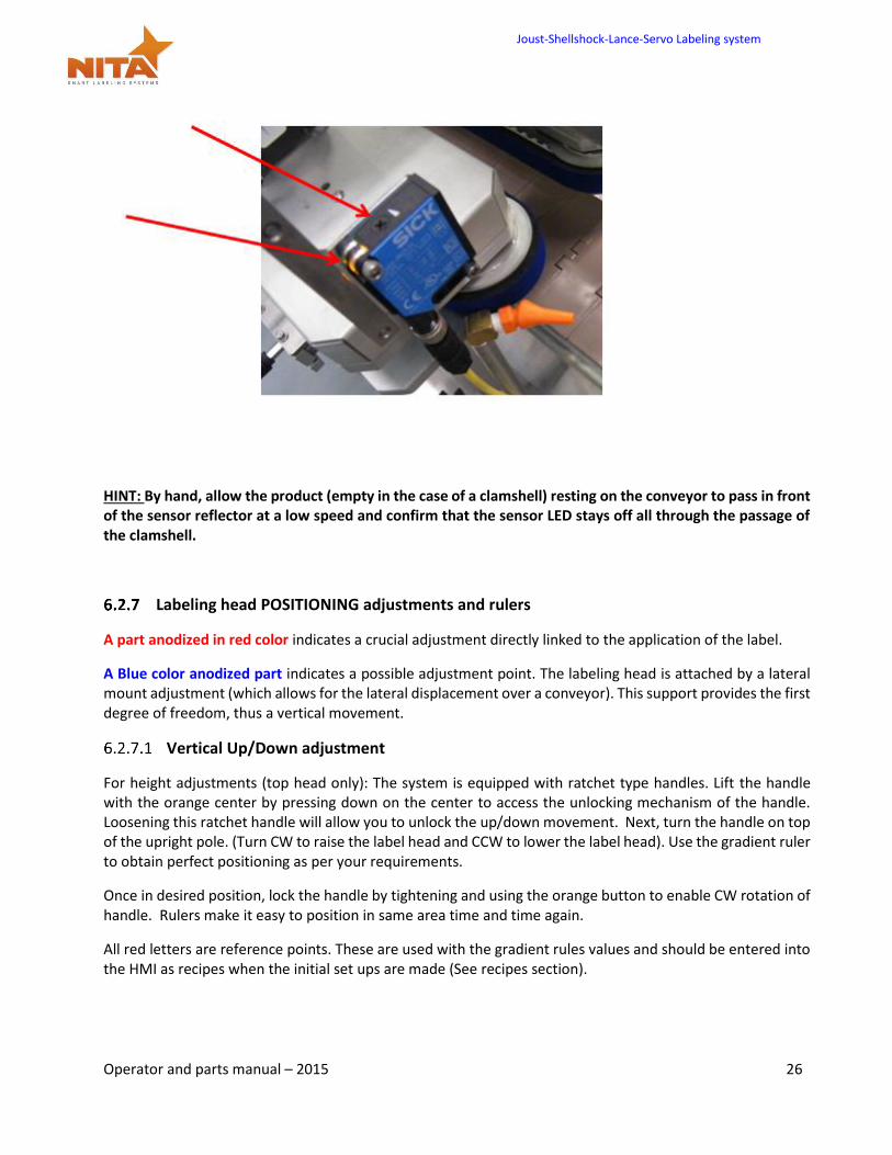
Product sensors
The product sensors are each connected to the electrical box via the input slot. Ideally when installed on the bracket correctly the sensitivity of the optical beam is reflecting off the reflector. Too sensitive and the sensor will not reach the reflector.
To ensure that the proper sensitivity is obtained:
Make sure that the sensor beam is aligned with the reflector on its opposite side of the product.
1) To adjust, use the sensitivity adjustment, control how far you beam will detect. Turn the adjustment (CCW) (see drawing) until the LED turns off.
2) Turn the adjustment (CW) slowly until the LED lights up again.
3) Continue turning CW for an additional ½ turn.
4) Check the calibration by simply placing your hand between the reflector and the sensor. The beam should be broken and the lead light should turn off. If this is the case, the sensor adjustment is set.
Joust-Shellshock-Lance-Servo Labeling system
Operator and parts manual – 2015 26
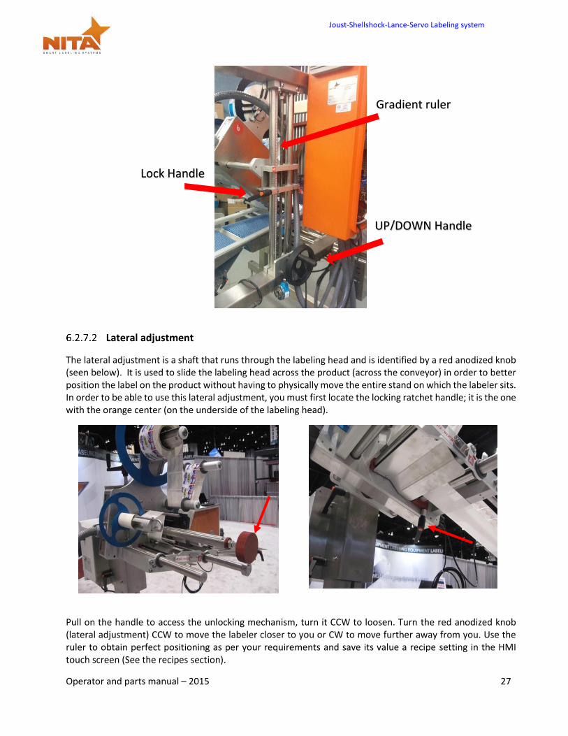
HINT: By hand, allow the product (empty in the case of a clamshell) resting on the conveyor to pass in front of the sensor reflector at a low speed and confirm that the sensor LED stays off all through the passage of the clamshell.
Labeling head POSITIONING adjustments and rulers
A part anodized in red color indicates a crucial adjustment directly linked to the application of the label.
A Blue color anodized part indicates a possible adjustment point. The labeling head is attached by a lateral mount adjustment (which allows for the lateral displacement over a conveyor). This support provides the first degree of freedom, thus a vertical movement.
Vertical Up/Down adjustment
For height adjustments (top head only): The system is equipped with ratchet type handles. Lift the handle with the orange center by pressing down on the center to access the unlocking mechanism of the handle. Loosening this ratchet handle will allow you to unlock the up/down movement. Next, turn the handle on top of the upright pole. (Turn CW to raise the label head and CCW to lower the label head). Use the gradient ruler to obtain perfect positioning as per your requirements.
Once in desired position, lock the handle by tightening and using the orange button to enable CW rotation of handle. Rulers make it easy to position in same area time and time again.
All red letters are reference points. These are used with the gradient rules values and should be entered into the HMI as recipes when the initial set ups are made (See recipes section).
Joust-Shellshock-Lance-Servo Labeling system
Operator and parts manual – 2015 27
Lateral adjustment
The lateral adjustment is a shaft that runs through the labeling head and is identified by a red anodized knob (seen below). It is used to slide the labeling head across the product (across the conveyor) in order to better position the label on the product without having to physically move the entire stand on which the labeler sits. In order to be able to use this lateral adjustment, you must first locate the locking ratchet handle; it is the one with the orange center (on the underside of the labeling head).
Pull on the handle to access the unlocking mechanism, turn it CCW to loosen. Turn the red anodized knob (lateral adjustment) CCW to move the labeler closer to you or CW to move further away from you. Use the ruler to obtain perfect positioning as per your requirements and save its value a recipe setting in the HMI touch screen (See the recipes section).
UP/DOWN Handle
Gradient ruler
Lock Handle
Joust-Shellshock-Lance-Servo Labeling system
Operator and parts manual – 2015 28
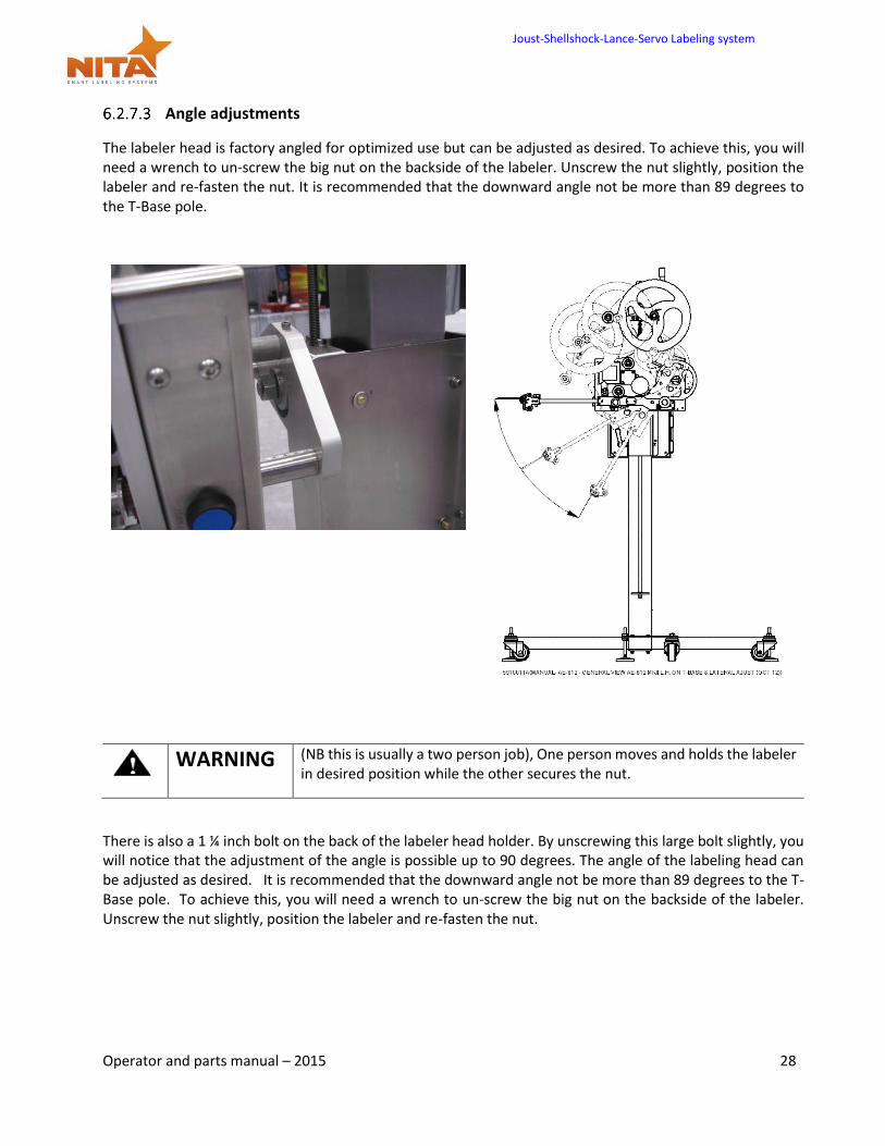
Angle adjustments
The labeler head is factory angled for optimized use but can be adjusted as desired. To achieve this, you will need a wrench to un-screw the big nut on the backside of the labeler. Unscrew the nut slightly, position the labeler and re-fasten the nut. It is recommended that the downward angle not be more than 89 degrees to the T-Base pole.
WARNING (NB this is usually a two person job), One person moves and holds the labeler
in desired position while the other secures the nut.
There is also a 1 ¼ inch bolt on the back of the labeler head holder. By unscrewing this large bolt slightly, you will notice that the adjustment of the angle is possible up to 90 degrees. The angle of the labeling head can be adjusted as desired. It is recommended that the downward angle not be more than 89 degrees to the T-Base pole. To achieve this, you will need a wrench to un-screw the big nut on the backside of the labeler. Unscrew the nut slightly, position the labeler and re-fasten the nut.
Joust-Shellshock-Lance-Servo Labeling system
Operator and parts manual – 2015 29
A good adjustment is when the exit of the label is at a 15 to 20 degree angle against the surface of application.
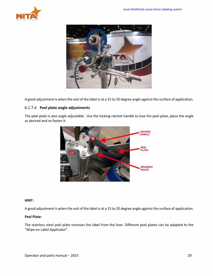
Peel plate angle adjustments
The peel plate is also angle adjustable. Use the locking ratchet handle to lose the peel plate, place the angle as desired and re-fasten it.
HINT:
A good adjustment is when the exit of the label is at a 15 to 20 degree angle against the surface of application.
Peel Plate:
The stainless steel peel plate removes the label from the liner. Different peel plates can be adapted to the “Wipe-on Label Applicator”.
Joust-Shellshock-Lance-Servo Labeling system
Operator and parts manual – 2015 30
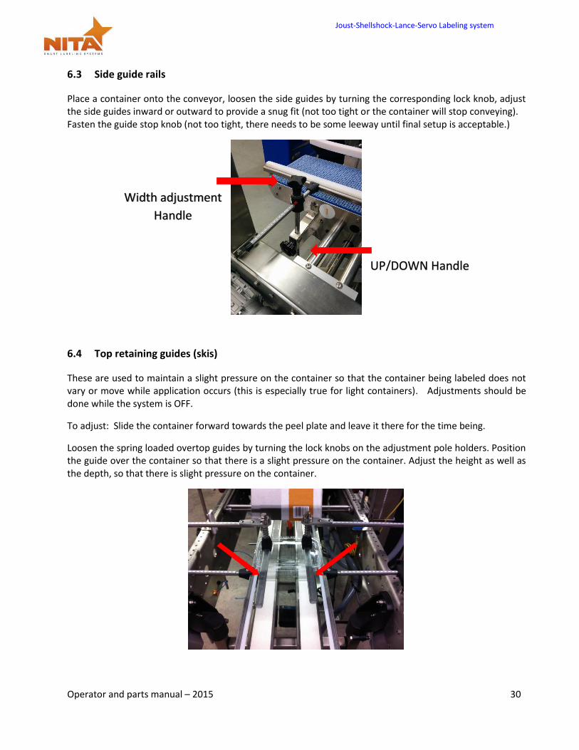
6.3 Side guide rails
Place a container onto the conveyor, loosen the side guides by turning the corresponding lock knob, adjust the side guides inward or outward to provide a snug fit (not too tight or the container will stop conveying). Fasten the guide stop knob (not too tight, there needs to be some leeway until final setup is acceptable.)
6.4 Top retaining guides (skis)
These are used to maintain a slight pressure on the container so that the container being labeled does not vary or move while application occurs (this is especially true for light containers). Adjustments should be done while the system is OFF.
To adjust: Slide the container forward towards the peel plate and leave it there for the time being.
Loosen the spring loaded overtop guides by turning the lock knobs on the adjustment pole holders. Position the guide over the container so that there is a slight pressure on the container. Adjust the height as well as the depth, so that there is slight pressure on the container.
Width adjustment
Handle
UP/DOWN Handle
Joust-Shellshock-Lance-Servo Labeling system
Operator and parts manual – 2015 31
HINT: You can slide the skis forward towards the peel plate so that the container is held for a maximum amount of time prior to labeling. This will provide more stability to the product although this may not be necessary for all products. Once positioned as desired, slightly fasten the lock knobs. Note the position of the gradient ruler value so that you can enter it in the HMI touch screen (See recipe section).
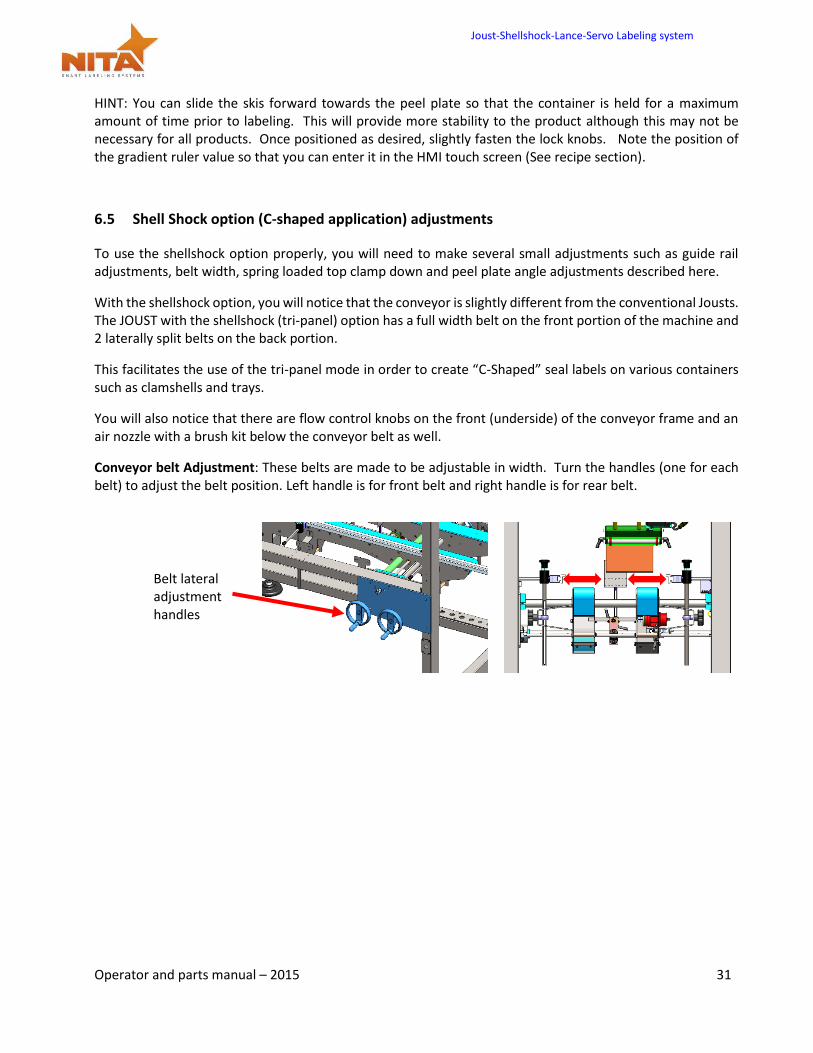
To use the shellshock option properly, you will need to make several small adjustments such as guide rail adjustments, belt width, spring loaded top clamp down and peel plate angle adjustments described here.
With the shellshock option, you will notice that the conveyor is slightly different from the conventional Jousts. The JOUST with the shellshock (tri-panel) option has a full width belt on the front portion of the machine and 2 laterally split belts on the back portion.
This facilitates the use of the tri-panel mode in order to create “C-Shaped” seal labels on various containers such as clamshells and trays.
You will also notice that there are flow control knobs on the front (underside) of the conveyor frame and an air nozzle with a brush kit below the conveyor belt as well.
Conveyor belt Adjustment: These belts are made to be adjustable in width. Turn the handles (one for each belt) to adjust the belt position. Left handle is for front belt and right handle is for rear belt.
Belt lateral adjustment handles
Joust-Shellshock-Lance-Servo Labeling system
Operator and parts manual – 2015 32
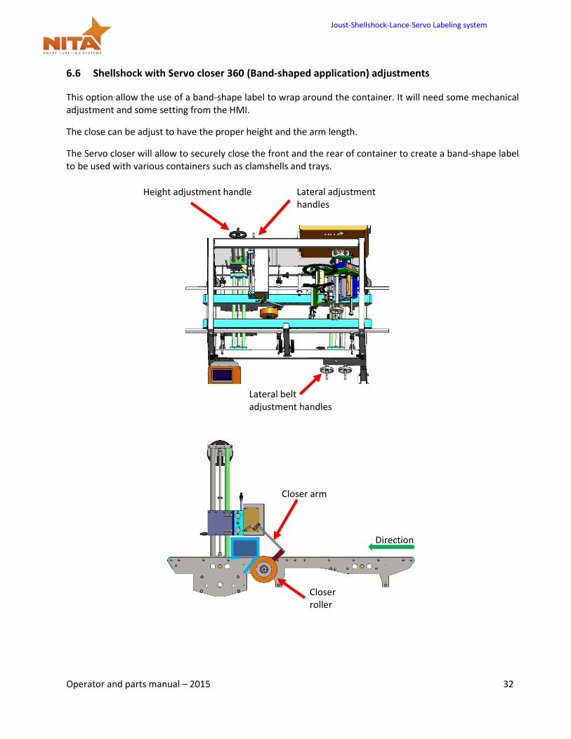
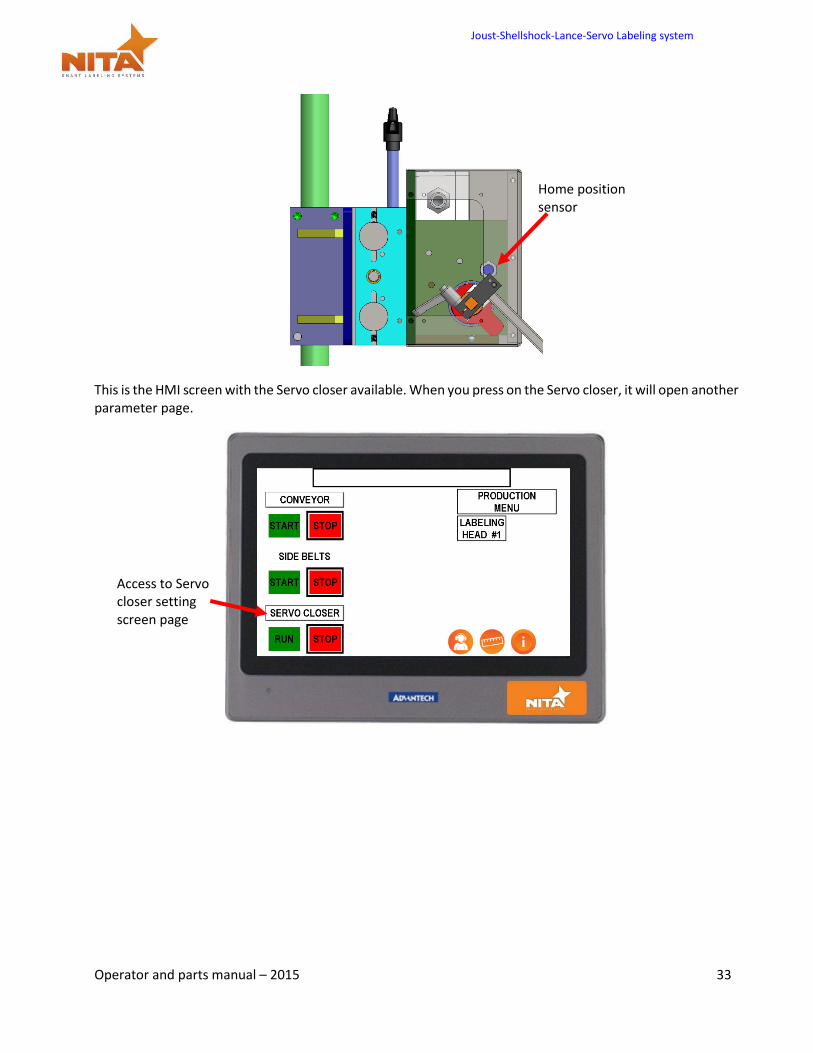
6.6 Shellshock with Servo closer 360 (Band-shaped application) adjustments
This option allow the use of a band-shape label to wrap around the container. It will need some mechanical adjustment and some setting from the HMI.
The close can be adjust to have the proper height and the arm length.
The Servo closer will allow to securely close the front and the rear of container to create a band-shape label to be used with various containers such as clamshells and trays.
Height adjustment handle
Closer arm
Lateral belt adjustment handles
Lateral adjustment handles
Closer roller
Direction
Joust-Shellshock-Lance-Servo Labeling system
Operator and parts manual – 2015 33
This is the HMI screen with the Servo closer available. When you press on the Servo closer, it will open another parameter page.
Access to Servo closer setting screen page
Home position sensor
Joust-Shellshock-Lance-Servo Labeling system
Operator and parts manual – 2015 34
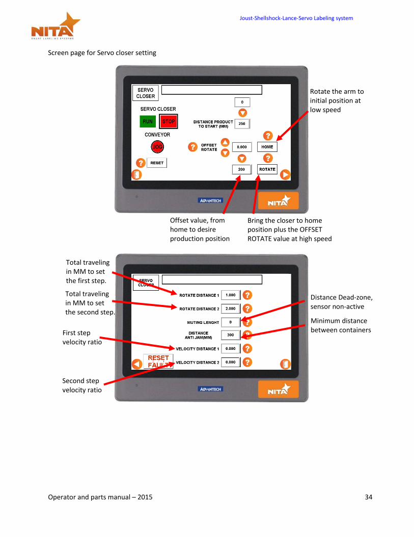
Screen page for Servo closer setting
Rotate the arm to initial position at low speed
Offset value, from home to desire production position
Bring the closer to home position plus the OFFSET ROTATE value at high speed
Total traveling in MM to set the first step.
Total traveling in MM to set the second step.
First step velocity ratio
Second step velocity ratio
Minimum distance between containers
Distance Dead-zone, sensor non-active
Joust-Shellshock-Lance-Servo Labeling system
Operator and parts manual – 2015 35
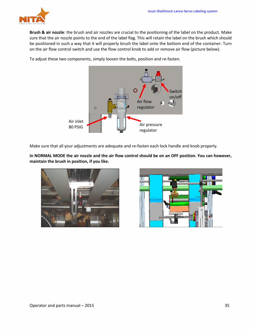
Brush & air nozzle: the brush and air nozzles are crucial to the positioning of the label on the product. Make sure that the air nozzle points to the end of the label flag. This will retain the label on the brush which should be positioned in such a way that it will properly brush the label onto the bottom end of the container. Turn on the air flow control switch and use the flow control knob to add or remove air flow (picture below).
To adjust these two components, simply loosen the bolts, position and re-fasten.
Make sure that all your adjustments are adequate and re-fasten each lock handle and knob properly.
In NORMAL MODE the air nozzle and the air flow control should be on an OFF position. You can however, maintain the brush in position, if you like.
Air inlet 80 PSIG
Air pressure regulator
Air flow regulator
Switch on/off
Joust-Shellshock-Lance-Servo Labeling system
Operator and parts manual – 2015 36
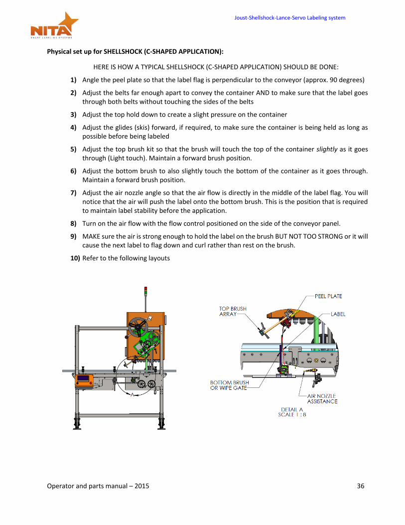
Physical set up for SHELLSHOCK (C-SHAPED APPLICATION):
HERE IS HOW A TYPICAL SHELLSHOCK (C-SHAPED APPLICATION) SHOULD BE DONE:
1) Angle the peel plate so that the label flag is perpendicular to the conveyor (approx. 90 degrees)
2) Adjust the belts far enough apart to convey the container AND to make sure that the label goes through both belts without touching the sides of the belts
3) Adjust the top hold down to create a slight pressure on the container
4) Adjust the glides (skis) forward, if required, to make sure the container is being held as long as possible before being labeled
5) Adjust the top brush kit so that the brush will touch the top of the container slightly as it goes through (Light touch). Maintain a forward brush position.
6) Adjust the bottom brush to also slightly touch the bottom of the container as it goes through. Maintain a forward brush position.
7) Adjust the air nozzle angle so that the air flow is directly in the middle of the label flag. You will notice that the air will push the label onto the bottom brush. This is the position that is required to maintain label stability before the application.
8) Turn on the air flow with the flow control positioned on the side of the conveyor panel.
9) MAKE sure the air is strong enough to hold the label on the brush BUT NOT TOO STRONG or it will cause the next label to flag down and curl rather than rest on the brush.
10) Refer to the following layouts
Joust-Shellshock-Lance-Servo Labeling system
Operator and parts manual – 2015 37
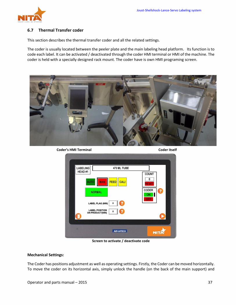
6.7 Thermal Transfer coder
This section describes the thermal transfer coder and all the related settings.
The coder is usually located between the peeler plate and the main labeling head platform. Its function is to code each label. It can be activated / deactivated through the coder HMI terminal or HMI of the machine. The coder is held with a specially designed rack mount. The coder have is own HMI programing screen.
Coder’s HMI Terminal Coder itself
Screen to activate / deactivate code
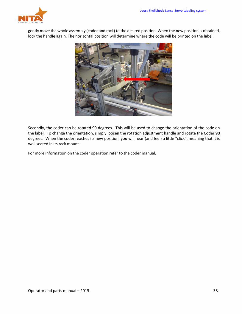
Mechanical Settings:
The Coder has positions adjustment as well as operating settings. Firstly, the Coder can be moved horizontally. To move the coder on its horizontal axis, simply unlock the handle (on the back of the main support) and
Joust-Shellshock-Lance-Servo Labeling system
Operator and parts manual – 2015 38
gently move the whole assembly (coder and rack) to the desired position. When the new position is obtained, lock the handle again. The horizontal position will determine where the code will be printed on the label.
Secondly, the coder can be rotated 90 degrees. This will be used to change the orientation of the code on the label. To change the orientation, simply loosen the rotation adjustment handle and rotate the Coder 90 degrees. When the coder reaches its new position, you will hear (and feel) a little “click”, meaning that it is well seated in its rack mount.
For more information on the coder operation refer to the coder manual.
Joust-Shellshock-Lance-Servo Labeling system
Operator and parts manual – 2015 39
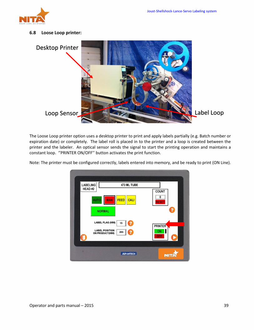
6.8 Loose Loop printer:
The Loose Loop printer option uses a desktop printer to print and apply labels partially (e.g. Batch number or expiration date) or completely. The label roll is placed in to the printer and a loop is created between the printer and the labeler. An optical sensor sends the signal to start the printing operation and maintains a constant loop. ‘’PRINTER ON/OFF’’ button activates the print function.
Note: The printer must be configured correctly, labels entered into memory, and be ready to print (ON Line).
Label Loop Loop Sensor
Desktop Printer
Joust-Shellshock-Lance-Servo Labeling system
Operator and parts manual – 2015 40
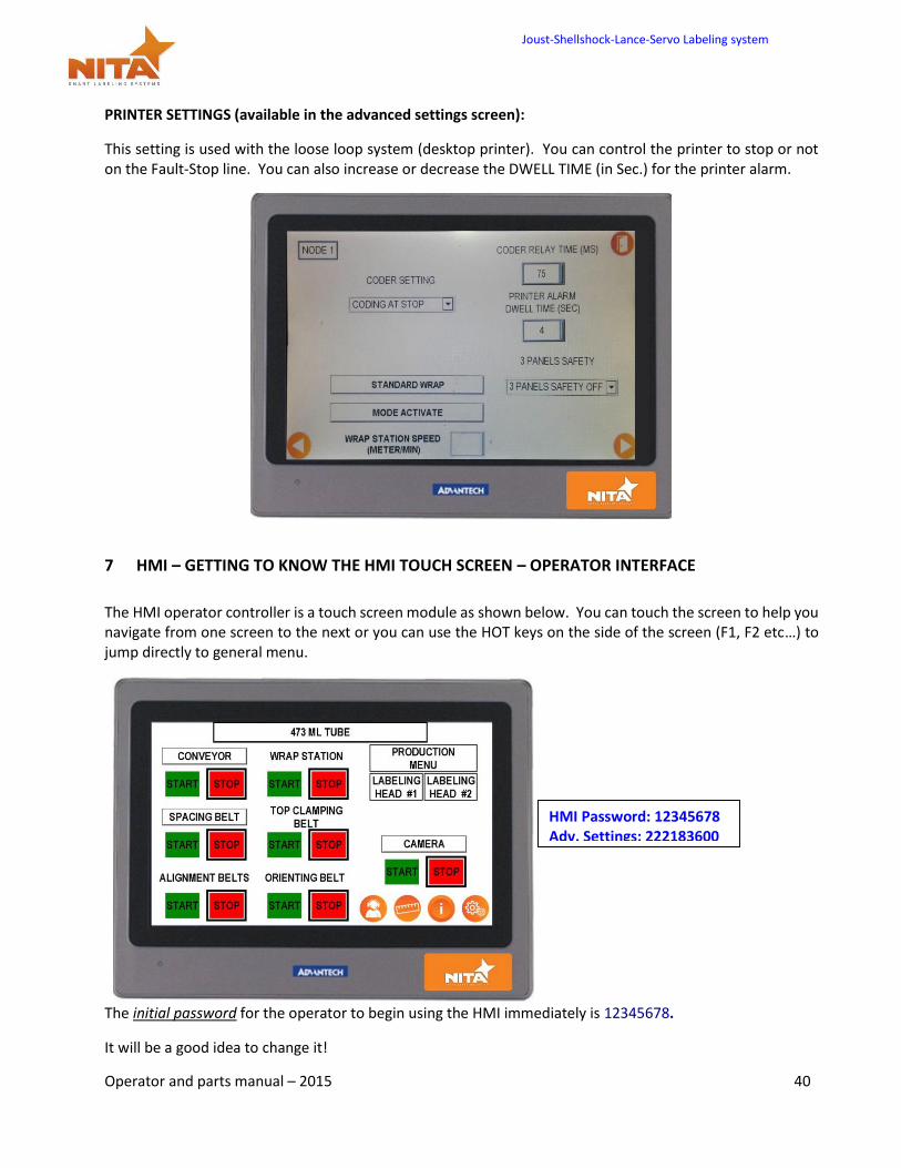
PRINTER SETTINGS (available in the advanced settings screen):
This setting is used with the loose loop system (desktop printer). You can control the printer to stop or not on the Fault-Stop line. You can also increase or decrease the DWELL TIME (in Sec.) for the printer alarm.
7 HMI – GETTING TO KNOW THE HMI TOUCH SCREEN – OPERATOR INTERFACE
The HMI operator controller is a touch screen module as shown below. You can touch the screen to help you navigate from one screen to the next or you can use the HOT keys on the side of the screen (F1, F2 etc…) to jump directly to general menu.
The initial password for the operator to begin using the HMI immediately is 12345678.
It will be a good idea to change it!
HMI Password: 12345678 Adv. Settings: 222183600
Joust-Shellshock-Lance-Servo Labeling system
Operator and parts manual – 2015 41
R E A D C A R E F U L Y
All settings and operations are done through the HMI- therefore moving the GAP sensor or the product sensor is a thing of the past. (IMPORTANT TO NEVER… physically move the sensors!)
The HMI is a touch screen interface that allows you to…
Control the length of label that slides out (called flagging)
Digitally control the GAP sensor positioning without physically moving the sensor at all
Digitally control the product sensor positioning. Product detection is done without physically moving the sensor
Get a clear indication (reference guide or recipe) of what the settings on the gradient rulers should be for maximum output for each pre-programmed sizes of the product.
Assign a “set-up” manager to change the default settings using a password
Get information pertaining to alarms (stoppage/ errors & why)
QUESTION MARK ON THE SCREEN…
The question mark icons lead to a ‘help’ screen which provides a brief explanation or tips on the adjustment method of the specific setting. This helps to minimize the time taken to make adjustments.
Joust-Shellshock-Lance-Servo Labeling system
Operator and parts manual – 2015 42
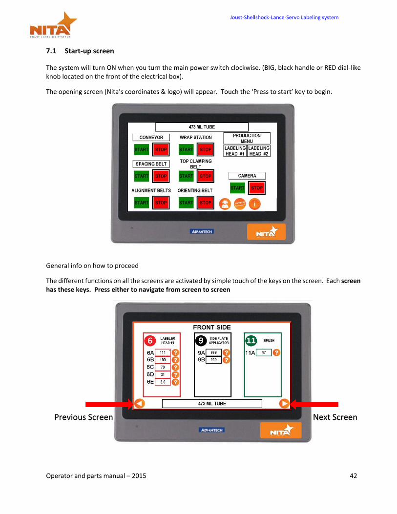
7.1 Start-up screen
The system will turn ON when you turn the main power switch clockwise. (BIG, black handle or RED dial-like knob located on the front of the electrical box).
The opening screen (Nita’s coordinates & logo) will appear. Touch the ‘Press to start’ key to begin.
General info on how to proceed
The different functions on all the screens are activated by simple touch of the keys on the screen. Each screen has these keys. Press either to navigate from screen to screen
Previous Screen Next Screen
Joust-Shellshock-Lance-Servo Labeling system
Operator and parts manual – 2015 43
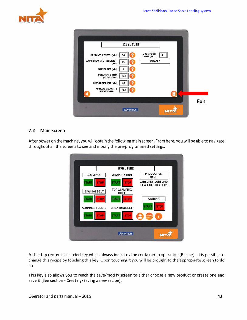
7.2 Main screen
After power on the machine, you will obtain the following main screen. From here, you will be able to navigate throughout all the screens to see and modify the pre-programmed settings.
At the top center is a shaded key which always indicates the container in operation (Recipe). It is possible to change this recipe by touching this key. Upon touching it you will be brought to the appropriate screen to do so.
This key also allows you to reach the save/modify screen to either choose a new product or create one and save it (See section - Creating/Saving a new recipe).
Exit
Joust-Shellshock-Lance-Servo Labeling system
Operator and parts manual – 2015 44
At the center of the main screen, you will find main component keys that allow you to control the settings/ parameters of the equipment’s main components.
For example, press the LABELING HEAD #1 key, a new screen will appear (see HMI section). That will allow you to access the said labeller settings.
The CONVEYOR icon, when pressed, will allow you to change the conveyor speed. (It is important to note that the conveyor speed is synchronized to all other motorized components. The faster the conveyor, the faster all motorised items will run, including the labellers see details on the page pertaining to the conveyor screen.
The options icon allows you to navigate to other options that may have been required to complete your system. Options can be: Pneumatic cylinders, closing stations, wrap station etc.
The button “SYSTEM CONFIGURATION” allows you to adjust time, language, screen brightness, contrast.
The button “ADVANCED SETTING” allows you to set internal parameters of the system (like “Password”) and must only be changed or modified by qualified technicians. These are password protected.
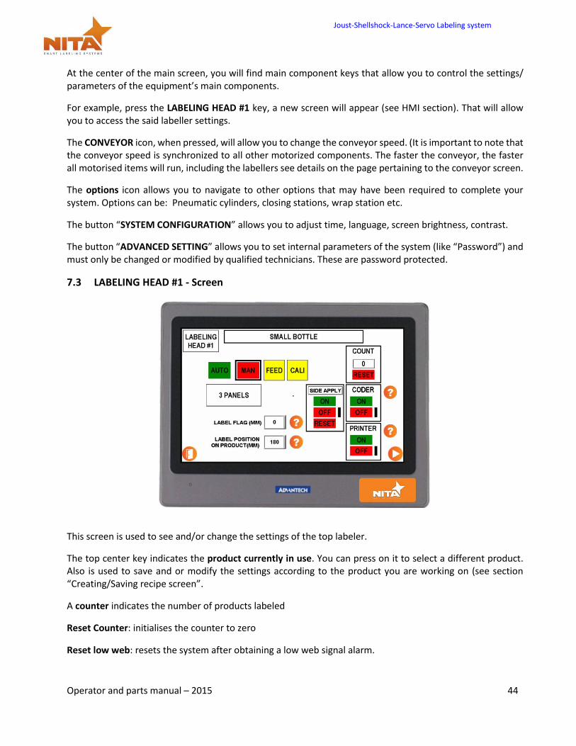
7.3 LABELING HEAD #1 - Screen
This screen is used to see and/or change the settings of the top labeler.
The top center key indicates the product currently in use. You can press on it to select a different product. Also is used to save and or modify the settings according to the product you are working on (see section “Creating/Saving recipe screen”.
A counter indicates the number of products labeled
Reset Counter: initialises the counter to zero
Reset low web: resets the system after obtaining a low web signal alarm.
Joust-Shellshock-Lance-Servo Labeling system
Operator and parts manual – 2015 45
NORMAL – 3 PANELS is used to switch from a normal mode to 3 Panel (which allows for the label to start feeding, stop and start feeding the same label again). This is used for long labels that need to be labeled on the front of a product. Generally, these labels rest on wipe gates, hence, they feed, wait and then release when the product goes through the wipe gates.
PRINTER ON – PRINTER OFF: is used to activate the print start. You need to have a tabletop printer in loose loop with a loop sensor (see Printer in loose loop section).
When the CALIBRATE key is pushed, (it simply keeps all the labels in memory from the sensor to the peel plate’s edge) all labels between the gap sensor and the peel plate’s edge will be fed. The system is now ready to begin labeling as long as the physical product set up has been made.
There is however an exception; When the label’s shape has a specific form, (non rectangular) and / or round. This exception dictates that if the label is of an odd shape or round, You MUST (after pressing calibrate) correct the label positioning using the GAP OFFSET parameter (under the OFFSETS key). See this explanation in (OFFSET) Setting for label application - screen.
The RULER VALUES key shows the optimum values given during set-up of a specific product. These values refer to the proper positioning of physical rulers on the system bearing the corresponding letters. Let these guide you for the setup of each product.
When entering a brand new product and ruler settings need to vary (Refer to section: RULER VALUES SCREEN).
The OFFSET key is used to see the pre-programmed distance for the labeling GAP and PRODUCT. For full details on this screen (See section OFFSET SECTION)
The button “CODER” allows you to adjust some coding parameter (See CODER section).
The STOP/START keys have the same use as already described.
Press MAN or AUTO switch from one mode to the next (Auto gets the trigger signal from the sensor to apply a label, while manual requires that you press FEED to obtain a label) (Seen below in manual mode).
The manual mode is handy while adjusting the settings of the labeler while performing physical changes where you do not want to waste the labels.
Joust-Shellshock-Lance-Servo Labeling system
Operator and parts manual – 2015 46
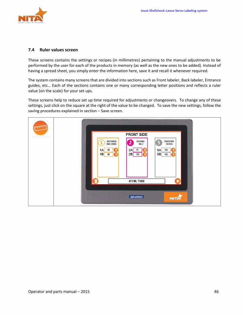
7.4 Ruler values screen
These screens contains the settings or recipes (in millimetres) pertaining to the manual adjustments to be performed by the user for each of the products in memory (as well as the new ones to be added). Instead of having a spread sheet, you simply enter the information here, save it and recall it whenever required.
The system contains many screens that are divided into sections such as Front labeler, Back labeler, Entrance guides, etc… Each of the sections contains one or many corresponding letter positions and reflects a ruler value (on the scale) for your set ups.
These screens help to reduce set up time required for adjustments or changeovers. To change any of these settings, just click on the square at the right of the value to be changed. To save the new settings, follow the saving procedures explained in section – Save screen.
Joust-Shellshock-Lance-Servo Labeling system
Operator and parts manual – 2015 47
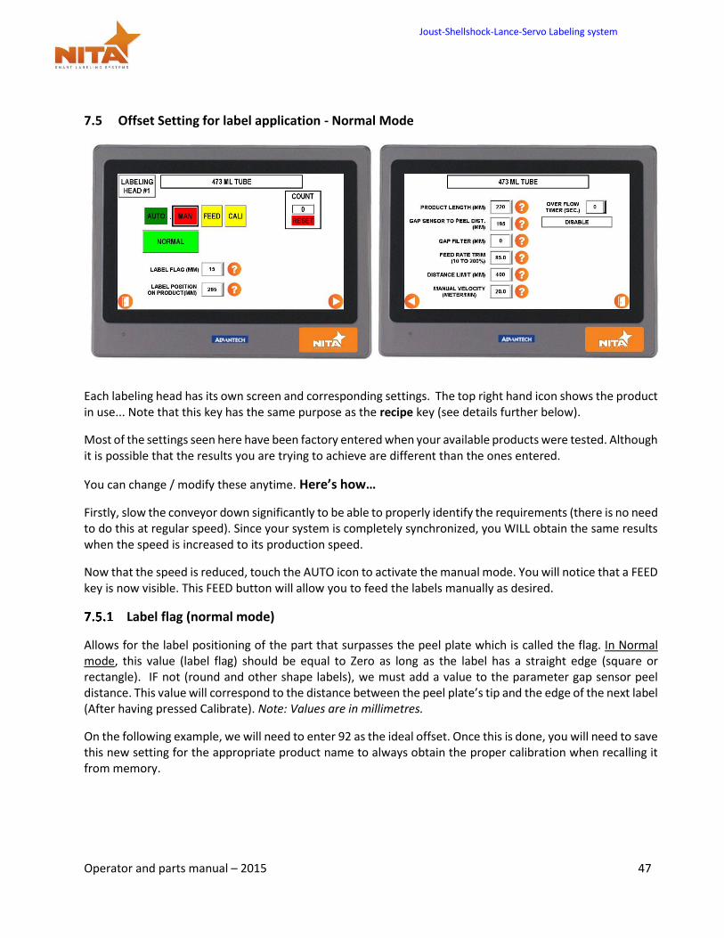
7.5 Offset Setting for label application - Normal Mode
Each labeling head has its own screen and corresponding settings. The top right hand icon shows the product in use... Note that this key has the same purpose as the recipe key (see details further below).
Most of the settings seen here have been factory entered when your available products were tested. Although it is possible that the results you are trying to achieve are different than the ones entered.
You can change / modify these anytime. Here’s how…
Firstly, slow the conveyor down significantly to be able to properly identify the requirements (there is no need to do this at regular speed). Since your system is completely synchronized, you WILL obtain the same results when the speed is increased to its production speed.
Now that the speed is reduced, touch the AUTO icon to activate the manual mode. You will notice that a FEED key is now visible. This FEED button will allow you to feed the labels manually as desired.
Label flag (normal mode)
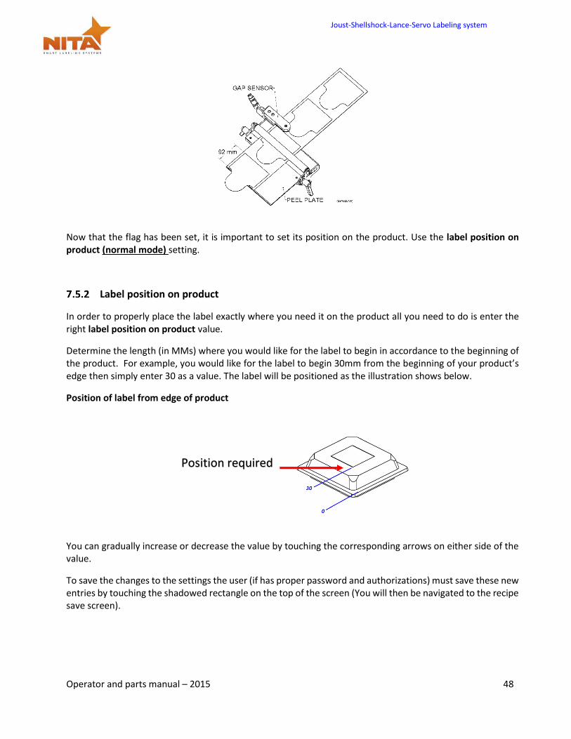
Allows for the label positioning of the part that surpasses the peel plate which is called the flag. In Normal mode, this value (label flag) should be equal to Zero as long as the label has a straight edge (square or rectangle). IF not (round and other shape labels), we must add a value to the parameter gap sensor peel distance. This value will correspond to the distance between the peel plate’s tip and the edge of the next label (After having pressed Calibrate). Note: Values are in millimetres.
On the following example, we will need to enter 92 as the ideal offset. Once this is done, you will need to save this new setting for the appropriate product name to always obtain the proper calibration when recalling it from memory.
Joust-Shellshock-Lance-Servo Labeling system
Operator and parts manual – 2015 48
Now that the flag has been set, it is important to set its position on the product. Use the label position on product (normal mode) setting.
Label position on product
In order to properly place the label exactly where you need it on the product all you need to do is enter the right label position on product value.
Determine the length (in MMs) where you would like for the label to begin in accordance to the beginning of the product. For example, you would like for the label to begin 30mm from the beginning of your product’s edge then simply enter 30 as a value. The label will be positioned as the illustration shows below.
Position of label from edge of product
You can gradually increase or decrease the value by touching the corresponding arrows on either side of the value.
To save the changes to the settings the user (if has proper password and authorizations) must save these new entries by touching the shadowed rectangle on the top of the screen (You will then be navigated to the recipe save screen).
Position required
Joust-Shellshock-Lance-Servo Labeling system
Operator and parts manual – 2015 49
Product length (normal mode)
This third setting has no use for the normal mode. It will not affect any changes no matter which value is set
Gap sensor to peel plate (normal mode)
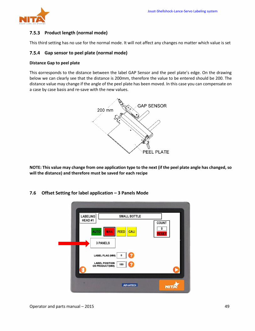
Distance Gap to peel plate
This corresponds to the distance between the label GAP Sensor and the peel plate’s edge. On the drawing below we can clearly see that the distance is 200mm, therefore the value to be entered should be 200. The distance value may change if the angle of the peel plate has been moved. In this case you can compensate on a case by case basis and re-save with the new values.
NOTE: This value may change from one application type to the next (if the peel plate angle has changed, so will the distance) and therefore must be saved for each recipe
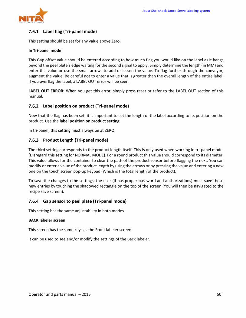
7.6 Offset Setting for label application – 3 Panels Mode
Joust-Shellshock-Lance-Servo Labeling system
Operator and parts manual – 2015 50
Label flag (Tri-panel mode)
This setting should be set for any value above Zero.
In Tri-panel mode
This Gap offset value should be entered according to how much flag you would like on the label as it hangs beyond the peel plate’s edge waiting for the second signal to apply. Simply determine the length (in MM) and enter this value or use the small arrows to add or lessen the value. To flag further through the conveyor, augment the value. Be careful not to enter a value that is greater than the overall length of the entire label. If you overflag the label, a LABEL OUT error will be seen.
LABEL OUT ERROR: When you get this error, simply press reset or refer to the LABEL OUT section of this manual.
Label position on product (Tri-panel mode)
Now that the flag has been set, it is important to set the length of the label according to its position on the product. Use the label position on product setting.
In tri-panel, this setting must always be at ZERO.
Product Length (Tri-panel mode)
The third setting corresponds to the product length itself. This is only used when working in tri-panel mode. (Disregard this setting for NORMAL MODE). For a round product this value should correspond to its diameter. This value allows for the container to clear the path of the product sensor before flagging the next. You can modify or enter a value of the product length by using the arrows or by pressing the value and entering a new one on the touch screen pop-up keypad (Which is the total length of the product).
To save the changes to the settings, the user (if has proper password and authorizations) must save these new entries by touching the shadowed rectangle on the top of the screen (You will then be navigated to the recipe save screen).
Gap sensor to peel plate (Tri-panel mode)
This setting has the same adjustability in both modes
BACK labeler screen
This screen has the same keys as the Front labeler screen.
It can be used to see and/or modify the settings of the Back labeler.
Joust-Shellshock-Lance-Servo Labeling system
Operator and parts manual – 2015 51
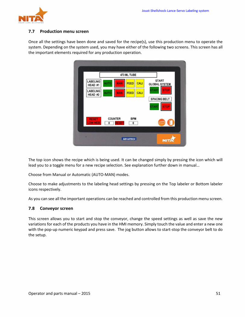
7.7 Production menu screen
Once all the settings have been done and saved for the recipe(s), use this production menu to operate the system. Depending on the system used, you may have either of the following two screens. This screen has all the important elements required for any production operation.
The top icon shows the recipe which is being used. It can be changed simply by pressing the icon which will lead you to a toggle menu for a new recipe selection. See explanation further down in manual…
Choose from Manual or Automatic (AUTO-MAN) modes.
Choose to make adjustments to the labeling head settings by pressing on the Top labeler or Bottom labeler icons respectively.
As you can see all the important operations can be reached and controlled from this production menu screen.
7.8 Conveyor screen
This screen allows you to start and stop the conveyor, change the speed settings as well as save the new variations for each of the products you have in the HMI memory. Simply touch the value and enter a new one with the pop-up numeric keypad and press save. The jog button allows to start-stop the conveyor belt to do the setup.
Joust-Shellshock-Lance-Servo Labeling system
Operator and parts manual – 2015 52
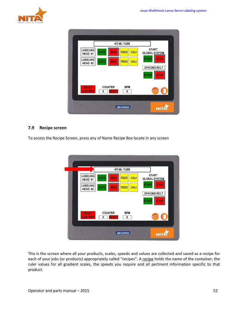
7.9 Recipe screen
To access the Recipe Screen, press any of Name Recipe Box locate in any screen
This is the screen where all your products, scales, speeds and values are collected and saved as a recipe for each of your jobs (or products) appropriately called “recipes”. A recipe holds the name of the container, the ruler values for all gradient scales, the speeds you require and all pertinent information specific to that product.
Joust-Shellshock-Lance-Servo Labeling system
Operator and parts manual – 2015 53
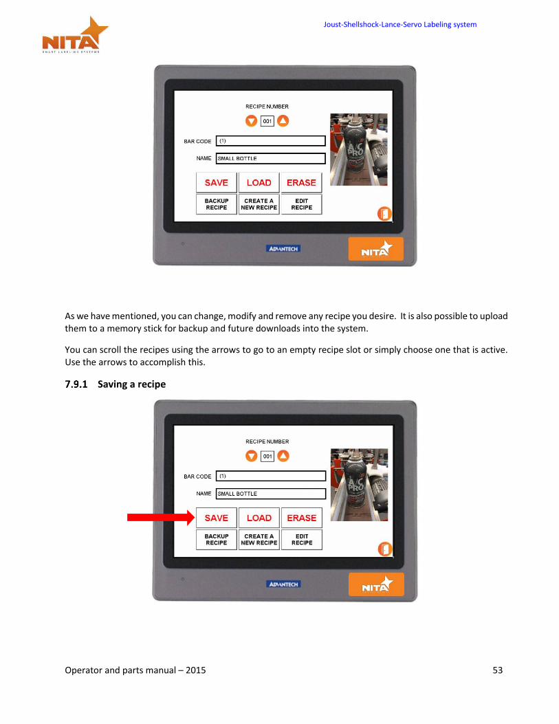
As we have mentioned, you can change, modify and remove any recipe you desire. It is also possible to upload them to a memory stick for backup and future downloads into the system.
You can scroll the recipes using the arrows to go to an empty recipe slot or simply choose one that is active. Use the arrows to accomplish this.
Saving a recipe
Joust-Shellshock-Lance-Servo Labeling system
Operator and parts manual – 2015 54
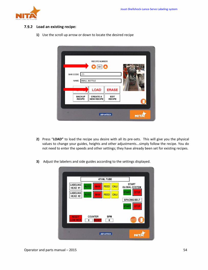
Load an existing recipe:
1) Use the scroll up arrow or down to locate the desired recipe
2) Press “LOAD” to load the recipe you desire with all its pre-sets. This will give you the physical values to change your guides, heights and other adjustments...simply follow the recipe. You do not need to enter the speeds and other settings; they have already been set for existing recipes.
3) Adjust the labelers and side guides according to the settings displayed.
Joust-Shellshock-Lance-Servo Labeling system
Operator and parts manual – 2015 55
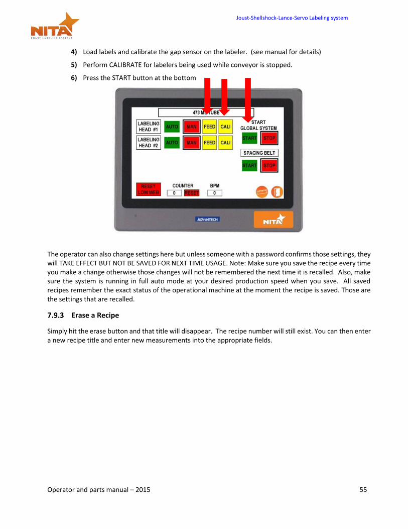
4) Load labels and calibrate the gap sensor on the labeler. (see manual for details)
5) Perform CALIBRATE for labelers being used while conveyor is stopped.
6) Press the START button at the bottom
The operator can also change settings here but unless someone with a password confirms those settings, they will TAKE EFFECT BUT NOT BE SAVED FOR NEXT TIME USAGE. Note: Make sure you save the recipe every time you make a change otherwise those changes will not be remembered the next time it is recalled. Also, make sure the system is running in full auto mode at your desired production speed when you save. All saved recipes remember the exact status of the operational machine at the moment the recipe is saved. Those are the settings that are recalled.
Erase a Recipe
Simply hit the erase button and that title will disappear. The recipe number will still exist. You can then enter a new recipe title and enter new measurements into the appropriate fields.
Joust-Shellshock-Lance-Servo Labeling system
Operator and parts manual – 2015 56
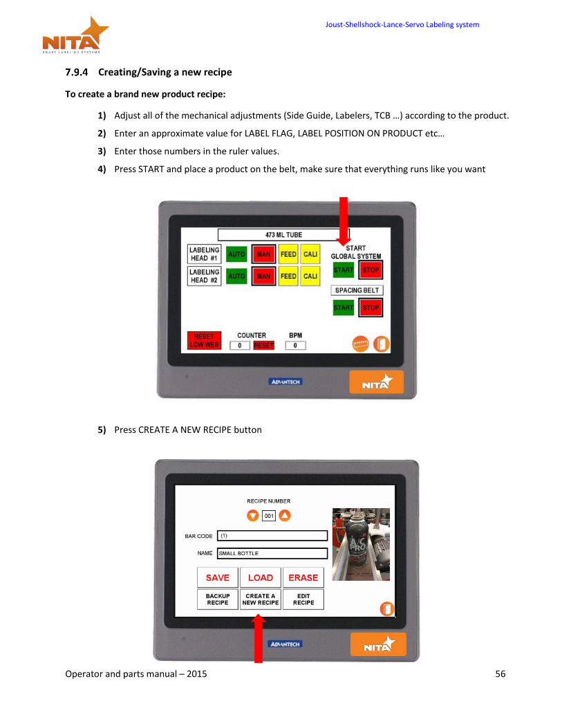
Creating/Saving a new recipe
To create a brand new product recipe:
1) Adjust all of the mechanical adjustments (Side Guide, Labelers, TCB …) according to the product.
2) Enter an approximate value for LABEL FLAG, LABEL POSITION ON PRODUCT etc…
3) Enter those numbers in the ruler values.
4) Press START and place a product on the belt, make sure that everything runs like you want
5) Press CREATE A NEW RECIPE button
Joust-Shellshock-Lance-Servo Labeling system
Operator and parts manual – 2015 57
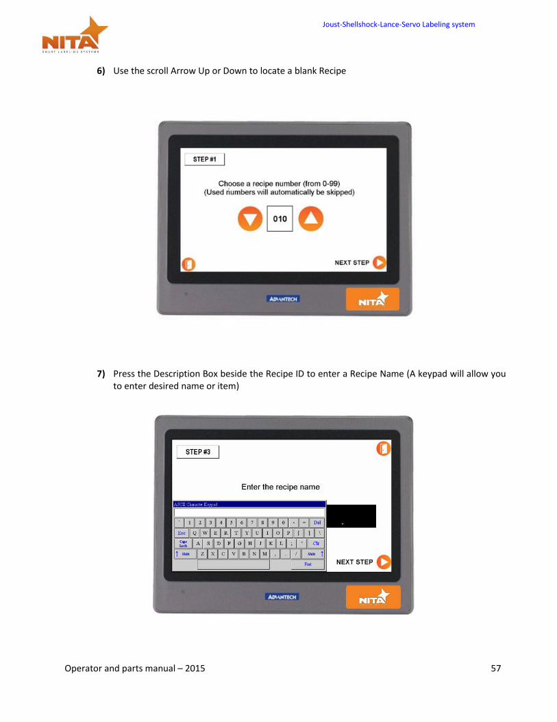
6) Use the scroll Arrow Up or Down to locate a blank Recipe
7) Press the Description Box beside the Recipe ID to enter a Recipe Name (A keypad will allow you to enter desired name or item)
Joust-Shellshock-Lance-Servo Labeling system
Operator and parts manual – 2015 58
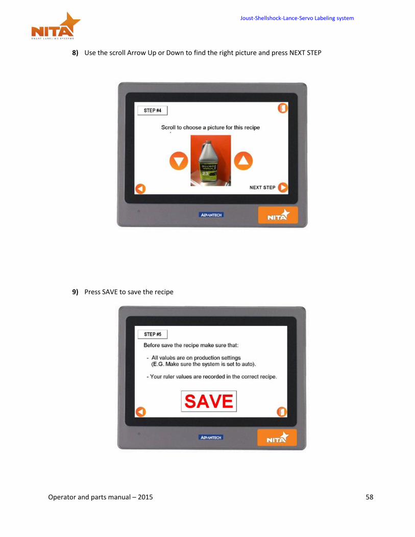
8) Use the scroll Arrow Up or Down to find the right picture and press NEXT STEP
9) Press SAVE to save the recipe
Joust-Shellshock-Lance-Servo Labeling system
Operator and parts manual – 2015 59
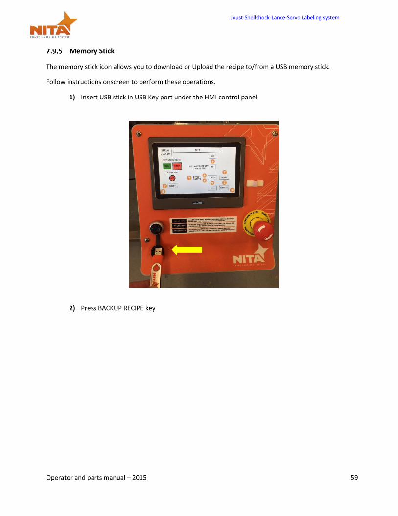
Memory Stick
The memory stick icon allows you to download or Upload the recipe to/from a USB memory stick.
Follow instructions onscreen to perform these operations.
1) Insert USB stick in USB Key port under the HMI control panel
2) Press BACKUP RECIPE key
Joust-Shellshock-Lance-Servo Labeling system
Operator and parts manual – 2015 60
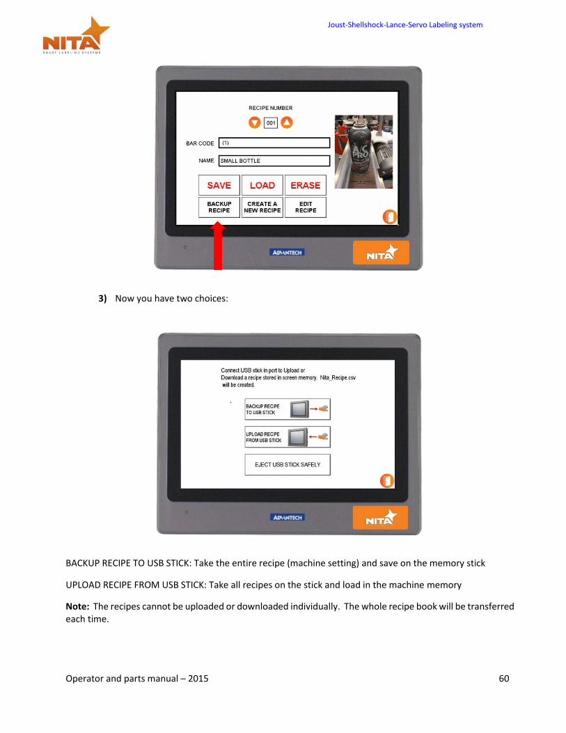
3) Now you have two choices:
BACKUP RECIPE TO USB STICK: Take the entire recipe (machine setting) and save on the memory stick
UPLOAD RECIPE FROM USB STICK: Take all recipes on the stick and load in the machine memory
Note: The recipes cannot be uploaded or downloaded individually. The whole recipe book will be transferred each time.
Joust-Shellshock-Lance-Servo Labeling system
Operator and parts manual – 2015 61
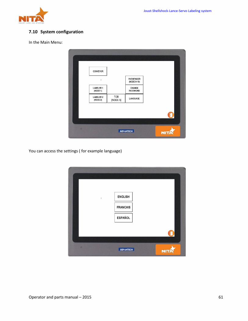
7.10 System configuration
In the Main Menu:
You can access the settings ( for example language)
Joust-Shellshock-Lance-Servo Labeling system
Operator and parts manual – 2015 62
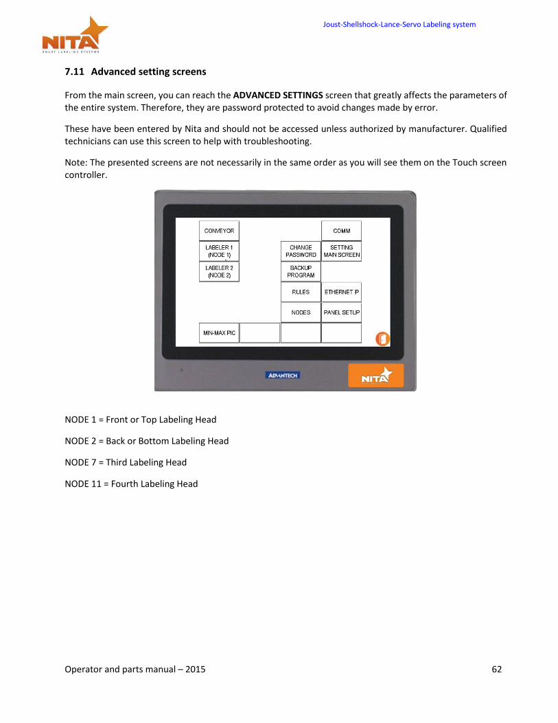
7.11 Advanced setting screens
From the main screen, you can reach the ADVANCED SETTINGS screen that greatly affects the parameters of the entire system. Therefore, they are password protected to avoid changes made by error.
These have been entered by Nita and should not be accessed unless authorized by manufacturer. Qualified technicians can use this screen to help with troubleshooting.
Note: The presented screens are not necessarily in the same order as you will see them on the Touch screen controller.
NODE 1 = Front or Top Labeling Head
NODE 2 = Back or Bottom Labeling Head
NODE 7 = Third Labeling Head
NODE 11 = Fourth Labeling Head
Joust-Shellshock-Lance-Servo Labeling system
Operator and parts manual – 2015 63
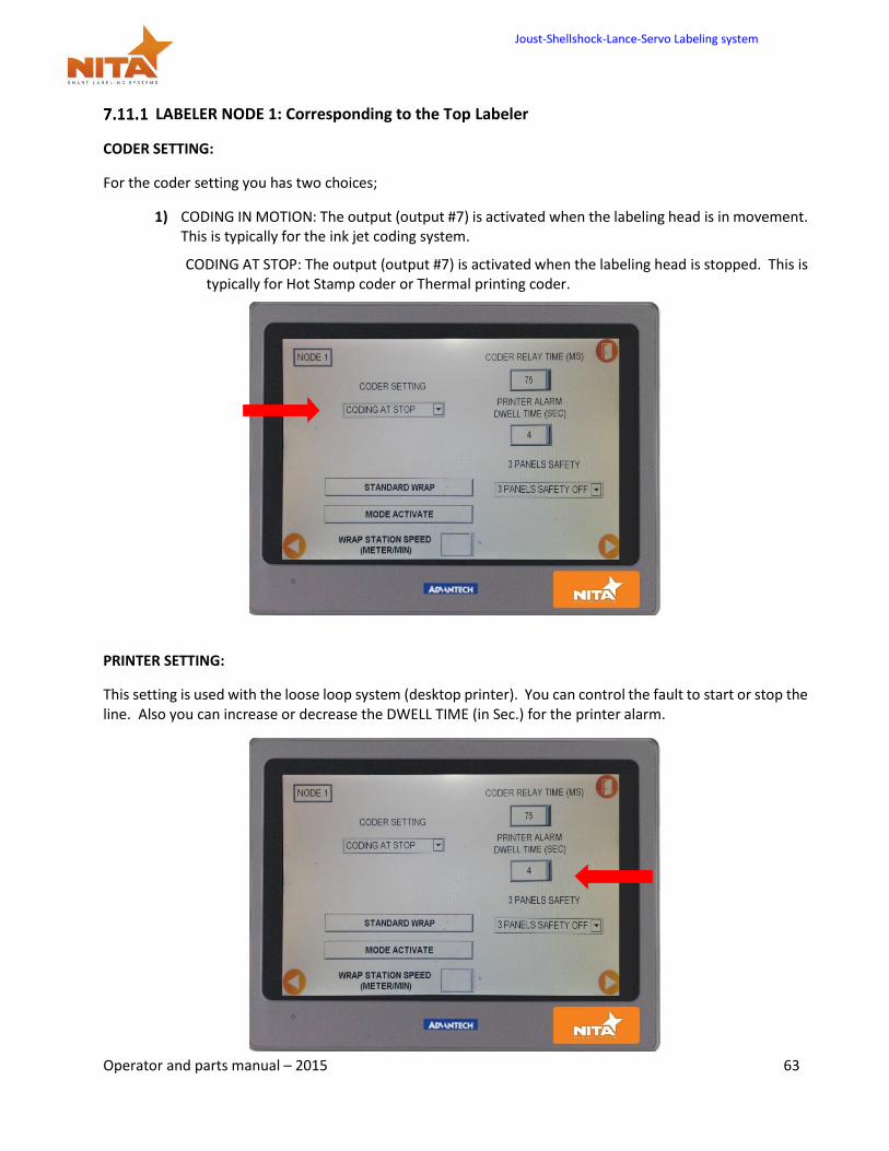
LABELER NODE 1: Corresponding to the Top Labeler
CODER SETTING:
For the coder setting you has two choices;
1) CODING IN MOTION: The output (output #7) is activated when the labeling head is in movement. This is typically for the ink jet coding system.
CODING AT STOP: The output (output #7) is activated when the labeling head is stopped. This is typically for Hot Stamp coder or Thermal printing coder.
PRINTER SETTING:
This setting is used with the loose loop system (desktop printer). You can control the fault to start or stop the line. Also you can increase or decrease the DWELL TIME (in Sec.) for the printer alarm.
Joust-Shellshock-Lance-Servo Labeling system
Operator and parts manual – 2015 64
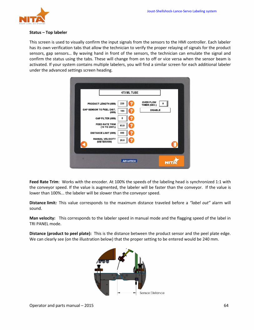
Status – Top labeler
This screen is used to visually confirm the input signals from the sensors to the HMI controller. Each labeler has its own verification tabs that allow the technician to verify the proper relaying of signals for the product sensors, gap sensors… By waving hand in front of the sensors, the technician can emulate the signal and confirm the status using the tabs. These will change from on to off or vice versa when the sensor beam is activated. If your system contains multiple labelers, you will find a similar screen for each additional labeler under the advanced settings screen heading.
Feed Rate Trim: Works with the encoder. At 100% the speeds of the labeling head is synchronized 1:1 with the conveyor speed. If the value is augmented, the labeler will be faster than the conveyor. If the value is lower than 100%... the labeler will be slower than the conveyor speed.
Distance limit: This value corresponds to the maximum distance traveled before a “label out” alarm will sound.
Man velocity: This corresponds to the labeler speed in manual mode and the flagging speed of the label in TRI PANEL mode.
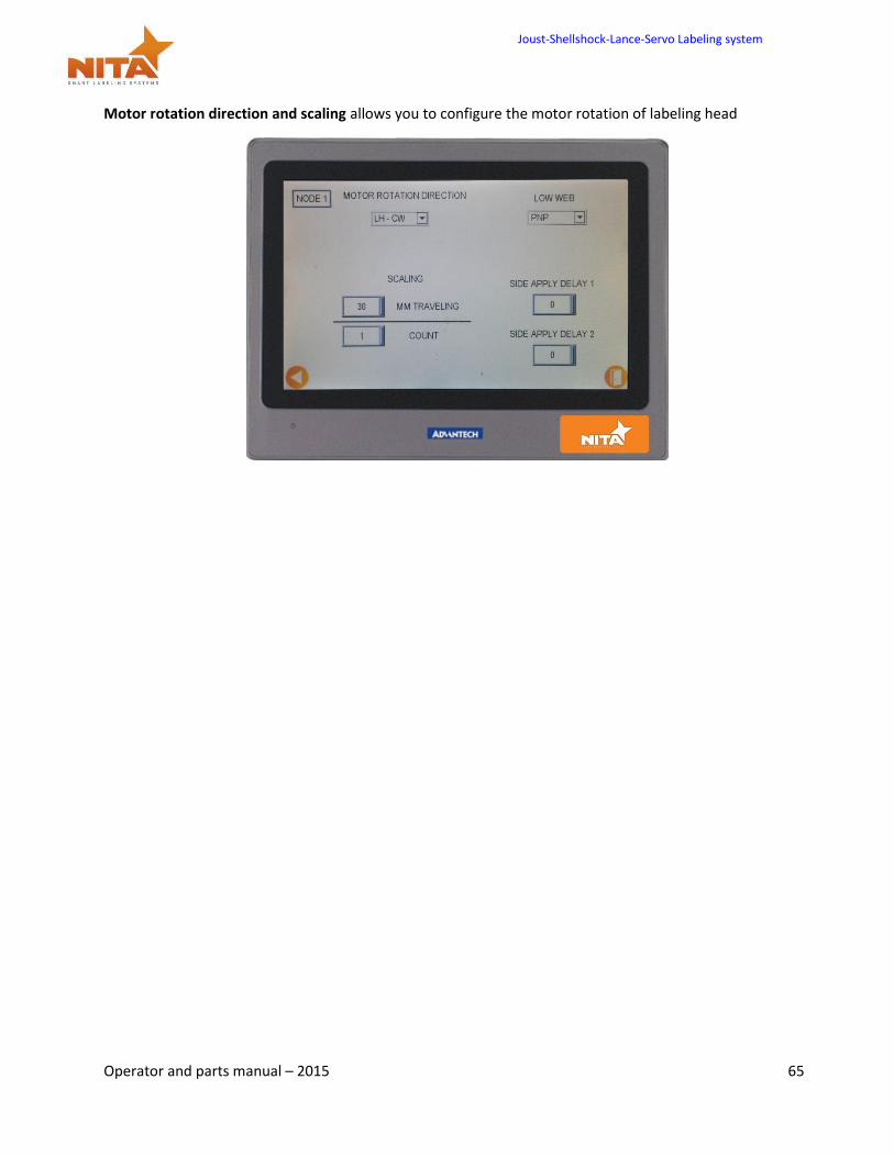
Distance (product to peel plate): This is the distance between the product sensor and the peel plate edge. We can clearly see (on the illustration below) that the proper setting to be entered would be 240 mm.
Joust-Shellshock-Lance-Servo Labeling system
Operator and parts manual – 2015 65
Motor rotation direction and scaling allows you to configure the motor rotation of labeling head
Joust-Shellshock-Lance-Servo Labeling system
Operator and parts manual – 2015 66
7.12 Alarm screen
Temperature screen Alarm
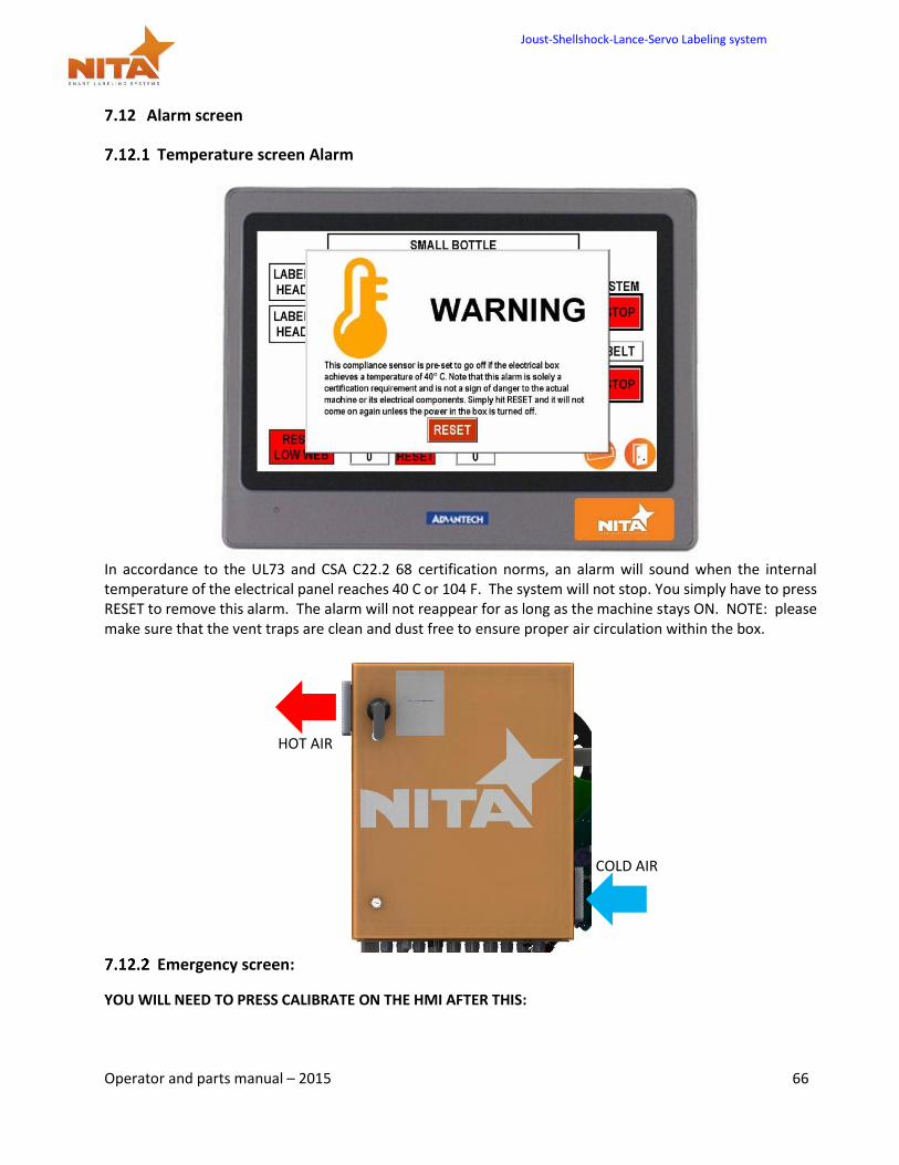
In accordance to the UL73 and CSA C22.2 68 certification norms, an alarm will sound when the internal temperature of the electrical panel reaches 40 C or 104 F. The system will not stop. You simply have to press RESET to remove this alarm. The alarm will not reappear for as long as the machine stays ON. NOTE: please make sure that the vent traps are clean and dust free to ensure proper air circulation within the box.
Emergency screen:
YOU WILL NEED TO PRESS CALIBRATE ON THE HMI AFTER THIS:
HOT AIR
COLD AIR
Joust-Shellshock-Lance-Servo Labeling system
Operator and parts manual – 2015 67
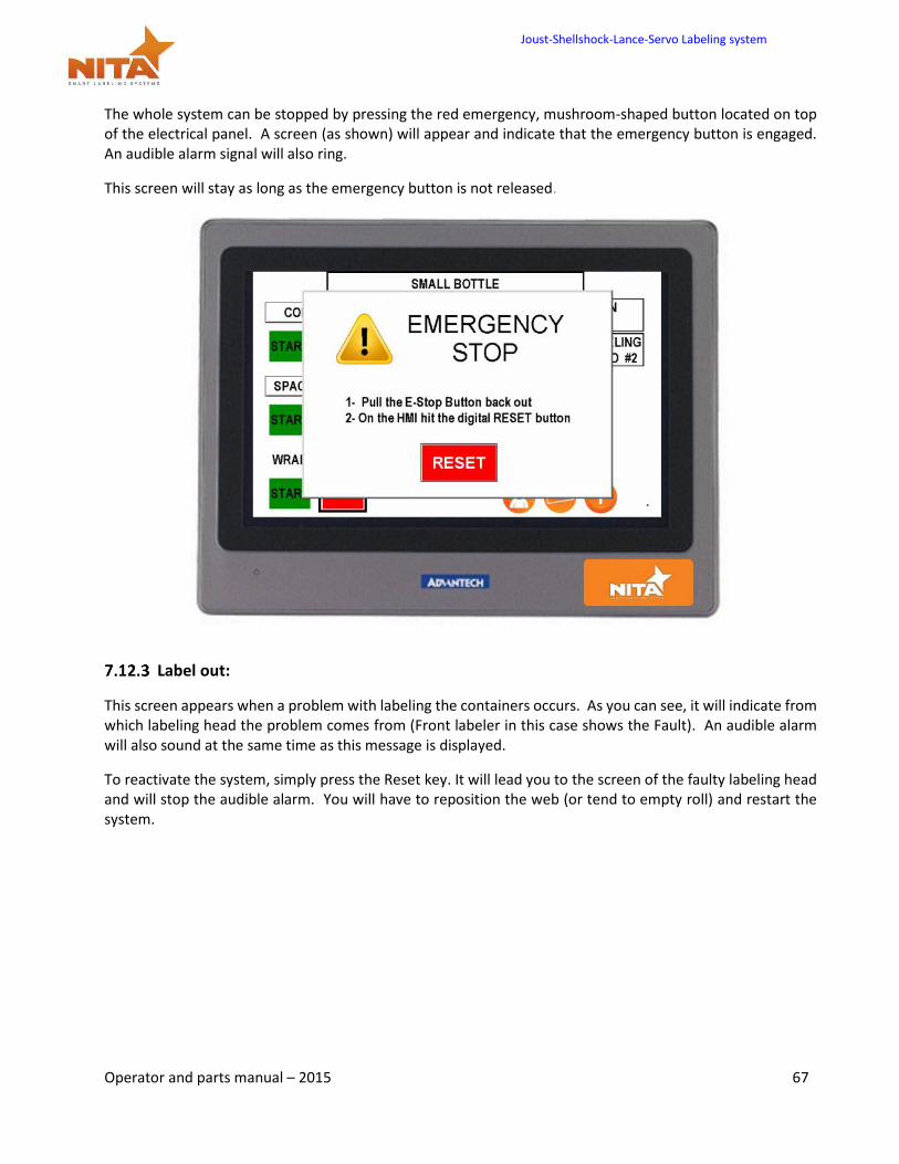
The whole system can be stopped by pressing the red emergency, mushroom-shaped button located on top of the electrical panel. A screen (as shown) will appear and indicate that the emergency button is engaged. An audible alarm signal will also ring.
This screen will stay as long as the emergency button is not released.
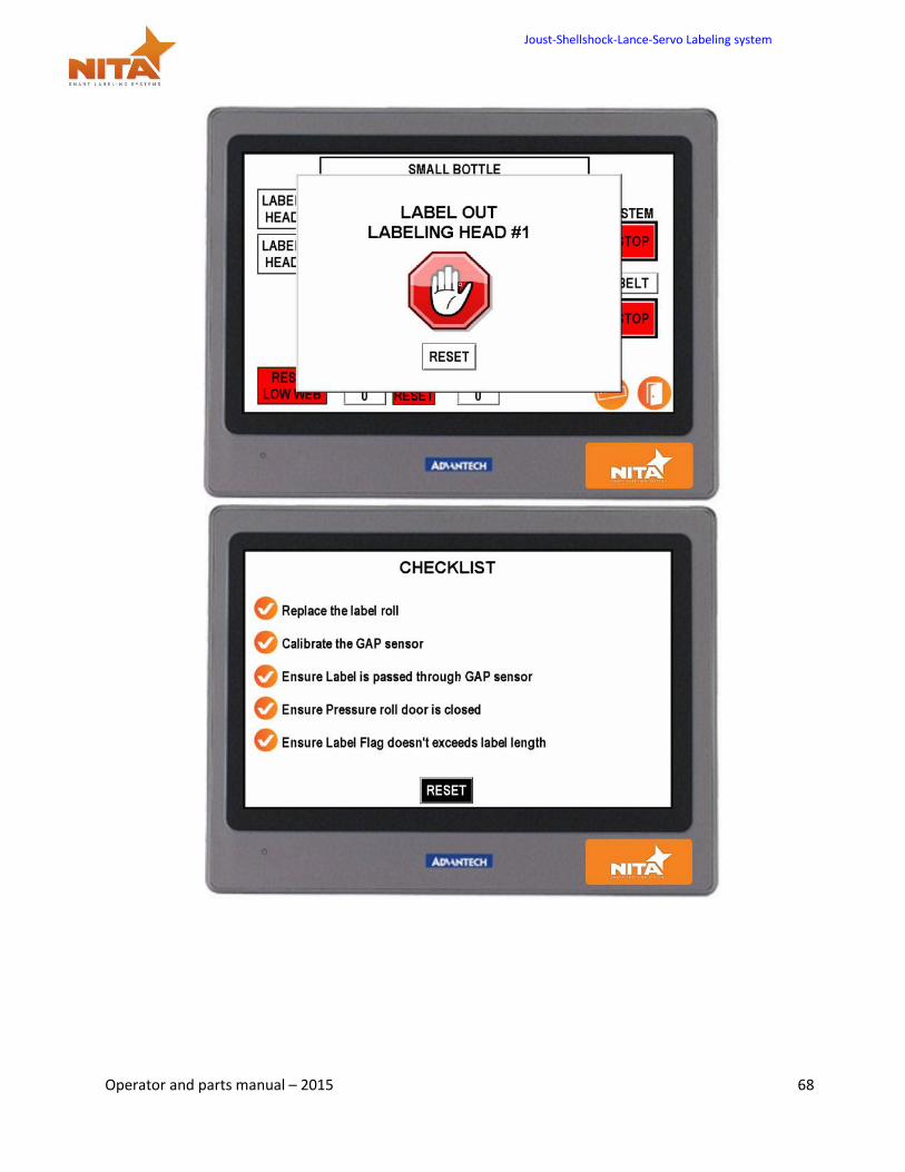
Label out:
This screen appears when a problem with labeling the containers occurs. As you can see, it will indicate from which labeling head the problem comes from (Front labeler in this case shows the Fault). An audible alarm will also sound at the same time as this message is displayed.
To reactivate the system, simply press the Reset key. It will lead you to the screen of the faulty labeling head and will stop the audible alarm. You will have to reposition the web (or tend to empty roll) and restart the system.
Joust-Shellshock-Lance-Servo Labeling system
Operator and parts manual – 2015 68
Joust-Shellshock-Lance-Servo Labeling system
Operator and parts manual – 2015 69
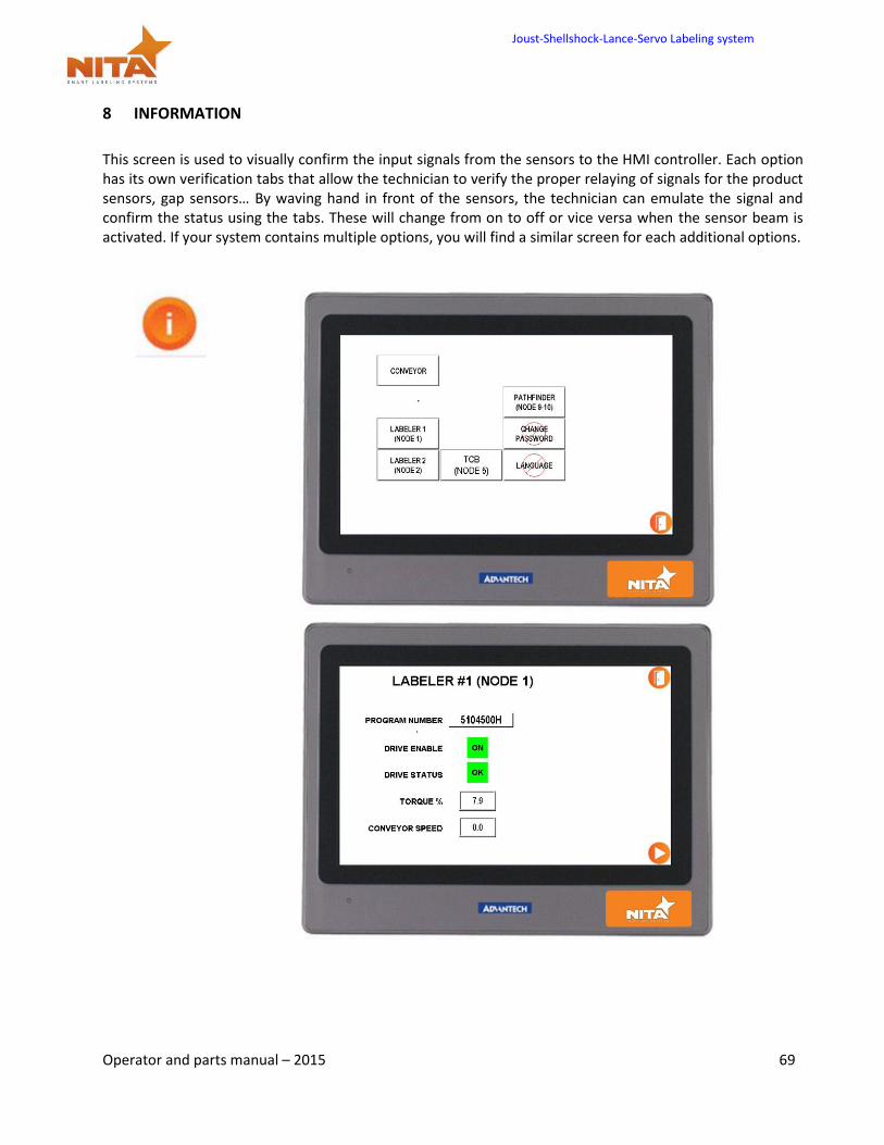
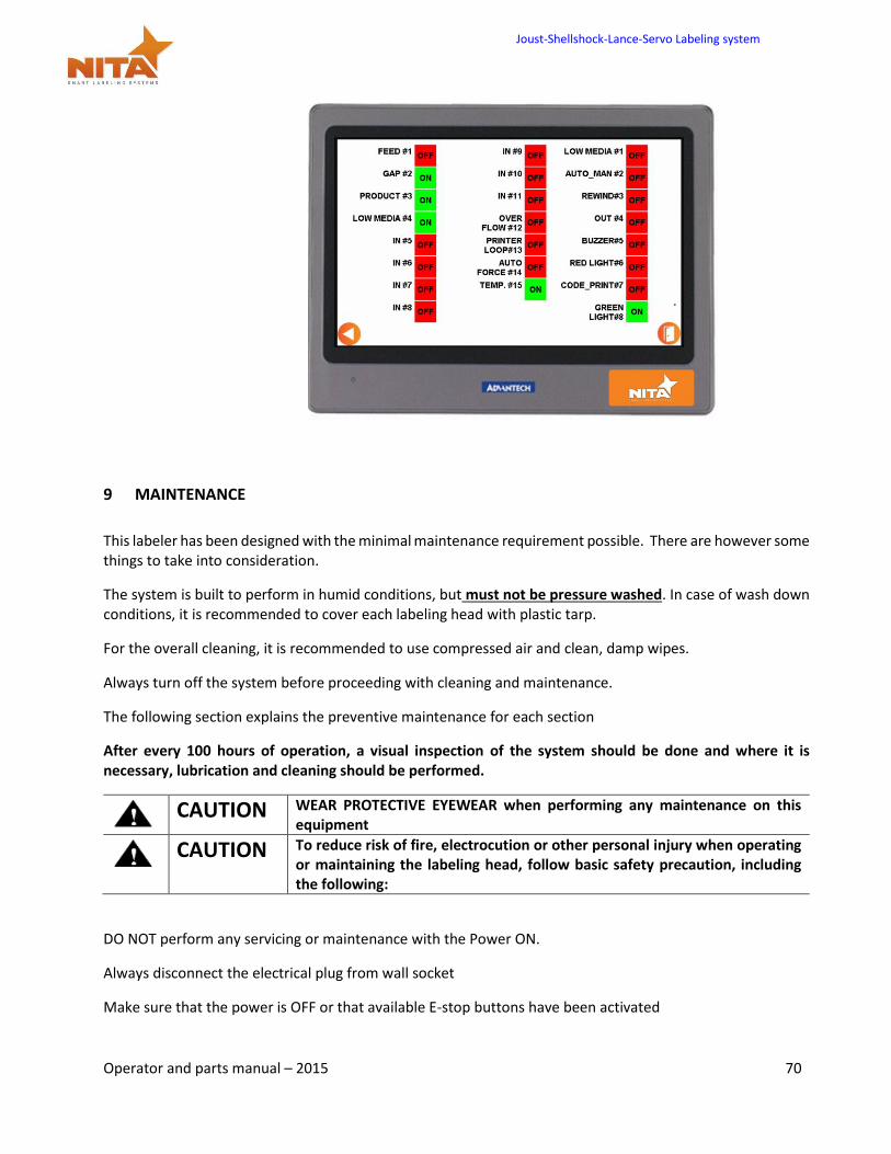
8 INFORMATION
This screen is used to visually confirm the input signals from the sensors to the HMI controller. Each option has its own verification tabs that allow the technician to verify the proper relaying of signals for the product sensors, gap sensors… By waving hand in front of the sensors, the technician can emulate the signal and confirm the status using the tabs. These will change from on to off or vice versa when the sensor beam is activated. If your system contains multiple options, you will find a similar screen for each additional options.
Joust-Shellshock-Lance-Servo Labeling system
Operator and parts manual – 2015 70
9 MAINTENANCE
This labeler has been designed with the minimal maintenance requirement possible. There are however some things to take into consideration.
The system is built to perform in humid conditions, but must not be pressure washed. In case of wash down conditions, it is recommended to cover each labeling head with plastic tarp.
For the overall cleaning, it is recommended to use compressed air and clean, damp wipes.
Always turn off the system before proceeding with cleaning and maintenance.
The following section explains the preventive maintenance for each section
After every 100 hours of operation, a visual inspection of the system should be done and where it is necessary, lubrication and cleaning should be performed.
CAUTION WEAR PROTECTIVE EYEWEAR when performing any maintenance on this
equipment
CAUTION To reduce risk of fire, electrocution or other personal injury when operating
or maintaining the labeling head, follow basic safety precaution, including the following:
DO NOT perform any servicing or maintenance with the Power ON.
Always disconnect the electrical plug from wall socket
Make sure that the power is OFF or that available E-stop buttons have been activated
Joust-Shellshock-Lance-Servo Labeling system
Operator and parts manual – 2015 71
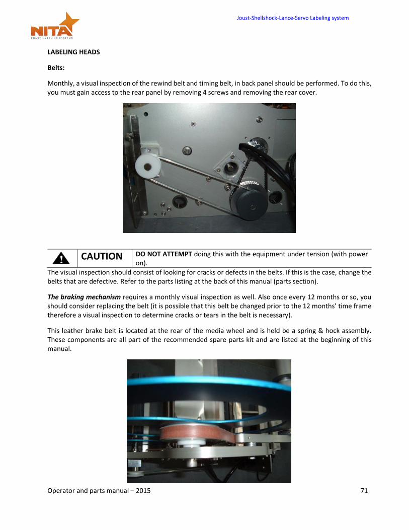
LABELING HEADS
Belts:
Monthly, a visual inspection of the rewind belt and timing belt, in back panel should be performed. To do this, you must gain access to the rear panel by removing 4 screws and removing the rear cover.
CAUTION DO NOT ATTEMPT doing this with the equipment under tension (with power
on).
The visual inspection should consist of looking for cracks or defects in the belts. If this is the case, change the belts that are defective. Refer to the parts listing at the back of this manual (parts section).
The braking mechanism requires a monthly visual inspection as well. Also once every 12 months or so, you should consider replacing the belt (it is possible that this belt be changed prior to the 12 months’ time frame therefore a visual inspection to determine cracks or tears in the belt is necessary).
This leather brake belt is located at the rear of the media wheel and is held be a spring & hock assembly. These components are all part of the recommended spare parts kit and are listed at the beginning of this manual.
Joust-Shellshock-Lance-Servo Labeling system
Operator and parts manual – 2015 72
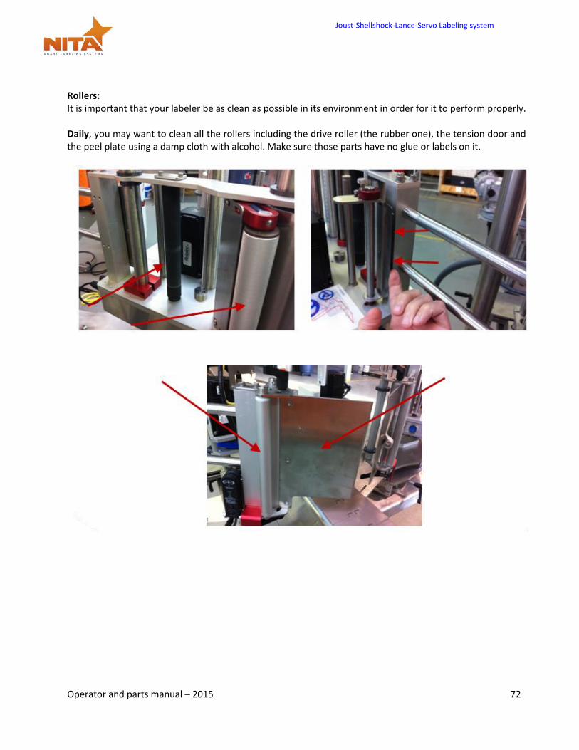
Rollers: It is important that your labeler be as clean as possible in its environment in order for it to perform properly. Daily, you may want to clean all the rollers including the drive roller (the rubber one), the tension door and the peel plate using a damp cloth with alcohol. Make sure those parts have no glue or labels on it.
Joust-Shellshock-Lance-Servo Labeling system
Operator and parts manual – 2015 73
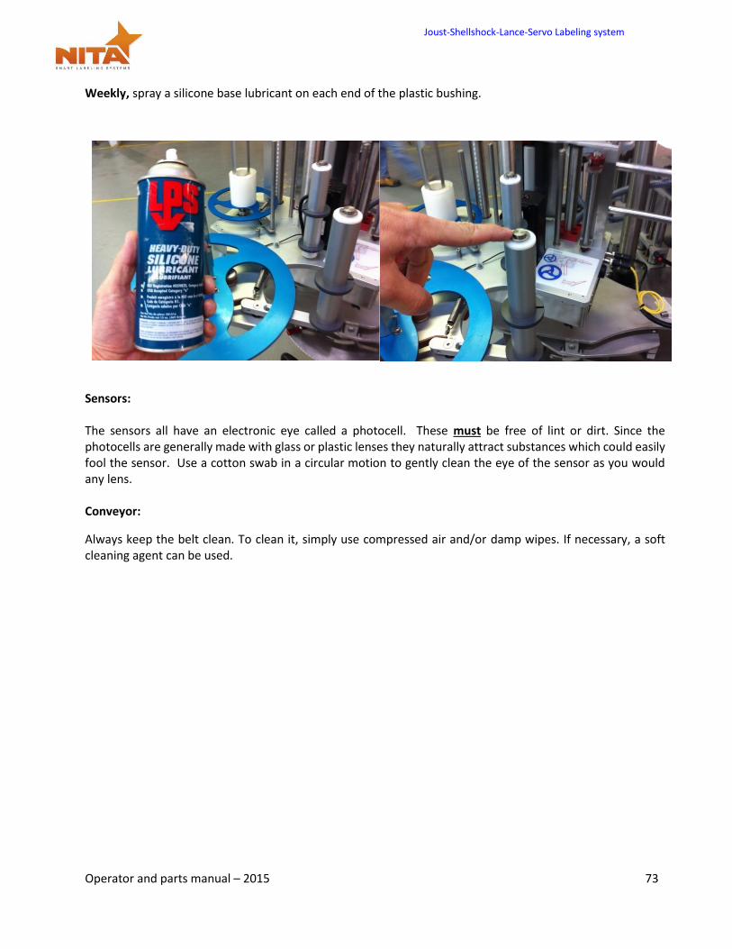
Weekly, spray a silicone base lubricant on each end of the plastic bushing.
Sensors: The sensors all have an electronic eye called a photocell. These must be free of lint or dirt. Since the photocells are generally made with glass or plastic lenses they naturally attract substances which could easily fool the sensor. Use a cotton swab in a circular motion to gently clean the eye of the sensor as you would any lens. Conveyor:
Always keep the belt clean. To clean it, simply use compressed air and/or damp wipes. If necessary, a soft cleaning agent can be used.
Joust-Shellshock-Lance-Servo Labeling system
Operator and parts manual – 2015 74
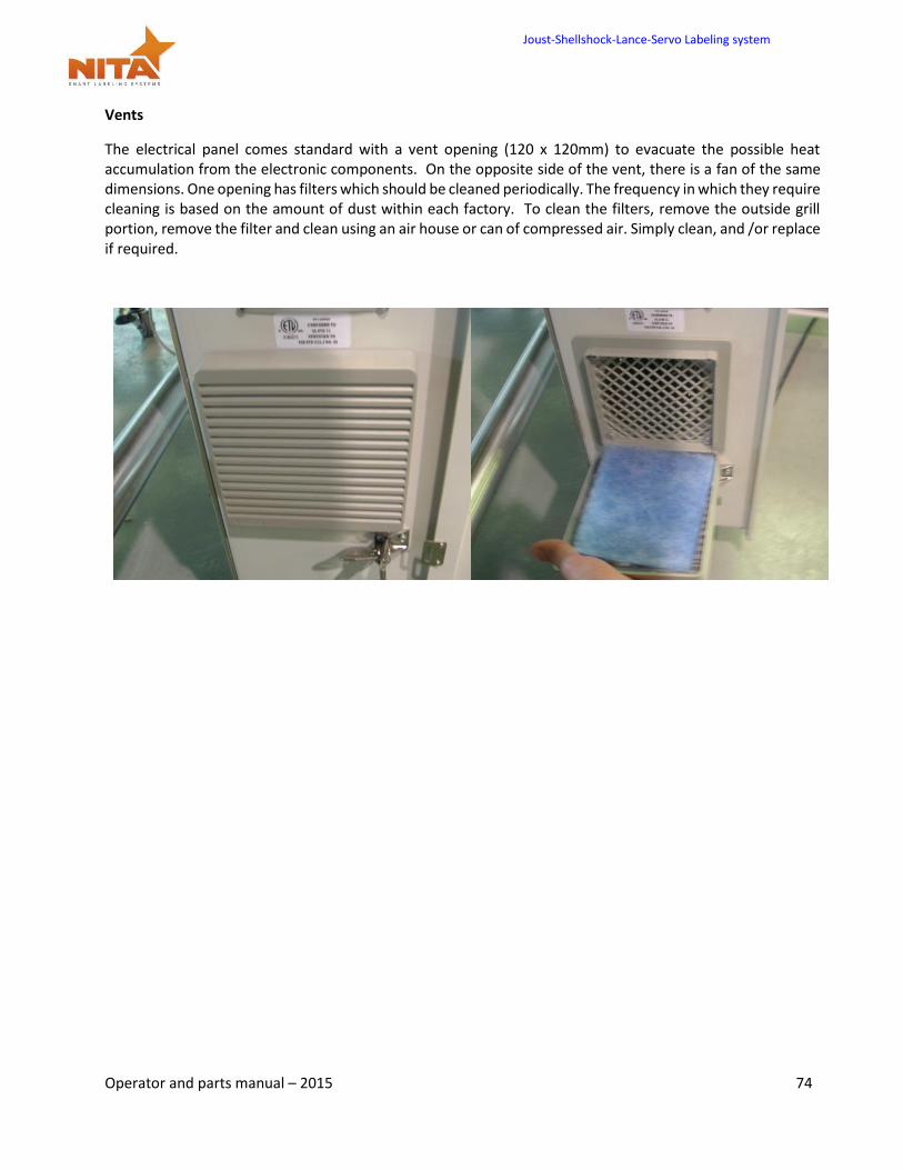
Vents
The electrical panel comes standard with a vent opening (120 x 120mm) to evacuate the possible heat accumulation from the electronic components. On the opposite side of the vent, there is a fan of the same dimensions. One opening has filters which should be cleaned periodically. The frequency in which they require cleaning is based on the amount of dust within each factory. To clean the filters, remove the outside grill portion, remove the filter and clean using an air house or can of compressed air. Simply clean, and /or replace if required.
Joust-Shellshock-Lance-Servo Labeling system
Operator and parts manual – 2015 75
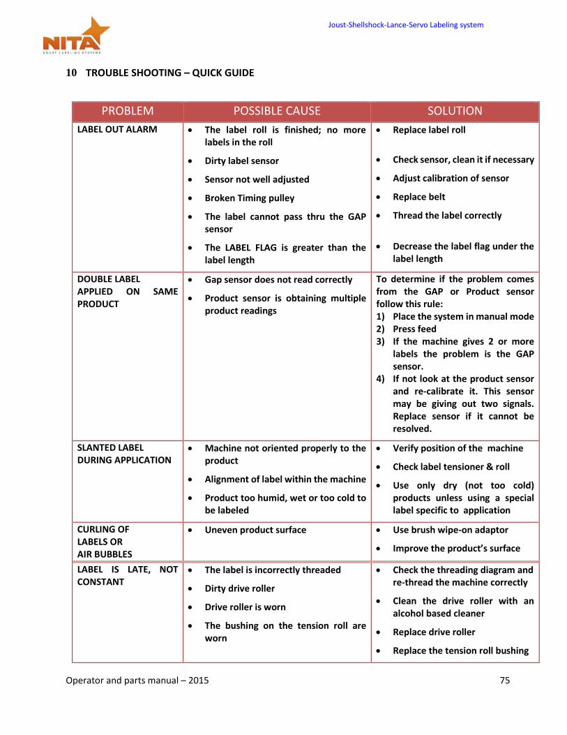
10 TROUBLE SHOOTING – QUICK GUIDE
PROBLEM POSSIBLE CAUSE SOLUTION
LABEL OUT ALARM The label roll is finished; no more labels in the roll
Dirty label sensor
Sensor not well adjusted
Broken Timing pulley
The label cannot pass thru the GAP sensor
The LABEL FLAG is greater than the label length
Replace label roll
Check sensor, clean it if necessary
Adjust calibration of sensor
Replace belt
Thread the label correctly
Decrease the label flag under the label length
DOUBLE LABEL APPLIED ON SAME PRODUCT
Gap sensor does not read correctly
Product sensor is obtaining multiple product readings
To determine if the problem comes from the GAP or Product sensor follow this rule: 1) Place the system in manual mode 2) Press feed 3) If the machine gives 2 or more
labels the problem is the GAP sensor.
4) If not look at the product sensor and re-calibrate it. This sensor may be giving out two signals. Replace sensor if it cannot be resolved.
SLANTED LABEL DURING APPLICATION
Machine not oriented properly to the product
Alignment of label within the machine
Product too humid, wet or too cold to be labeled
Verify position of the machine
Check label tensioner & roll
Use only dry (not too cold) products unless using a special label specific to application
CURLING OF LABELS OR AIR BUBBLES
Uneven product surface Use brush wipe-on adaptor
Improve the product’s surface
LABEL IS LATE, NOT CONSTANT
The label is incorrectly threaded
Dirty drive roller
Drive roller is worn
The bushing on the tension roll are worn
Check the threading diagram and re-thread the machine correctly
Clean the drive roller with an alcohol based cleaner
Replace drive roller
Replace the tension roll bushing
Joust-Shellshock-Lance-Servo Labeling system
Operator and parts manual – 2015 76
11 WARRANTY
The standard warranty period for this Nita equipment is 12 months following invoicing. The warranty covers all parts with consideration taken towards reasonable use and normal wear and tear. Not covered by warranty are parts that have a limited wear factor, any required labor by Nita and any shipping to or from Nita of defective or new parts. Prior to return to Nita, parts must be verified defective. The regular hours covered by the Nita warranty fall under the Nita business hours which are from 8:00 a.m. to 5:00 p.m. Monday through Friday Eastern time.
Return of defective parts
To return a defective part, you need to get a RMA number from Nita. Specify the serial number of the equipment, the client’s name, address and phone number, contact name and the nature of the problem.
To get a replacement part, you must produce a purchase order as you would with any regular part order. You will be billed for the new part and credited for the defective one after evaluation. If the part is determined to be defective due to improper use, no credit will be issued. Note: shipping charges for the new part and for the return of the defective one are at your expense.
Proprietorship and Risk of Loss
NITA reserves ownership of all equipment ordered by (END USER) until complete payment is received. NITA has the right to claim and repossess any equipment which has not been paid on date, wherever it is, whether it has been installed or not, and to use any means necessary or useful to exercise said right, at (END USER’S) expenses.
Notwithstanding NITA’s reservation of ownership, (END USER) becomes fully responsible for loss of or damages to NITA’s equipment, as of the date where NITA made the equipment available for pick-up by (END USER). Appropriate Use of Equipment
The equipment supplied to the end user by Nita are to be used for the sole purpose for which they were intended and must follow Nita’s specifications on usage as well as appropriate functions. Nita will not assume any responsibility for any inappropriate use or modifications to the said equipment other than for the use it was initially built for.
The warranty will cease to apply forthwith if, in NITA’s opinion, the equipment has been used abnormally or in an abusive manner, of it has not been properly maintained, if it has not been carried on a truck equipped with an air-ride suspension when required by NITA or if it has been used or maintained contrary to the owner’s manual provided by NITA.
Joust-Shellshock-Lance-Servo Labeling system
Operator and parts manual – 2015 77
Responsibility Limits
The solution put forth has been prepared with the information that has been provided to Nita by the end user. Subsequently, Nita cannot assume any responsibility for the exactitude, precision and validity of the information which was supplied. Moreover, Nita cannot be held responsible for (a) any damages, direct or indirect, secondary, or accessory , including, without limitations, the loss of profit, workflow interruption, loss of production, loss of profits and other; (b) any and all damages claimed against the end user by a third party ; (c) all or any damages caused to the property of end user or any other third party; (d) any or all damages resulting in an act from end user or third party, major force, or act of God, unforeseen cause, or event.
With all reservation, in the eventuality where the responsibility is that of Nita relative to any defect of quality of said equipment or proposed solution Nita would be able to Accept the responsibility, to its entire discretion, with the replacement of part of or the said equipment or solution. By a compatible or identical equipment or solution or by a reimbursement of value agreed upon. In no case can Nita’s responsibility exceed the total monetary sums received for the said defective equipment or solution.
Joust-Shellshock-Lance-Servo Labeling system
Operator and parts manual – 2015 78
12 PARTS LIST
Part # Description Qty
5101906 BASE KIT AE612-MKII (includes all below parts) 1
5123806 ROLLER KIT L3.000 FOR TENSION ROLLER ASSY 1
8212008 FLOW CONTROL BOTH FEMALE THREADS (for Shellshock only) 1
8249001 AIR ASSIST FLAT NOZZLE (for Shellshock only) 1
Joust-Shellshock-Lance-Servo Labeling system
Operator and parts manual – 2015 82
13 MANUFACTURER’S COORDINATES
Ultimately, the dealer which sold you the machine should be your first contact as they have been trained to perform any work on these devices and troubleshooting.
Should you require any additional information about our equipment, feel free to call us: