Profibus DP Slave Communication 1 Operator Interface Profibus DP Slave Communication Abstract Red Lion Controls G3 HMI (Human Machine Interface), CR3000 HMI, Graphite ® Core Controller, Graphite Edge Controller, Graphite HMI (with Module), Modular Controller Enhanced Master, and DSP (Data Station Plus) now support Profibus communication via optional communication cards. Products: G3 HMI (Human Machine Interface), CR3000 HMI, Graphite Core Controller, Graphite Edge Controller, Graphite HMI (with Module), Modular Controller Enhanced Master, and DSP Use Case This document introduces Profibus DP and describes how to set up a G3 HMI with an S7300 PLC, CPU315-2DP via Profibus. Setting up a CR3000 HMI, Graphite Controller, Graphite HMI, Modular Controller Enhanced Master, or DSP would be similar. This document is not intended to provide a detailed description of Profibus. Instead, it provides an overview of the concepts and terms necessary to perform the set up process. Required Software: Crimson 3.1, Crimson, 3.0, or Crimson 2.0 Required Firmware: Crimson 2.0, Build 273 or later Tech Note 30
Red Lion Controls G3 HMI (Human Machine Interface), CR3000 HMI, Graphite® Core Controller, Graphite Edge Controller, Graphite HMI (with Module), Modular Controller Enhanced Master, and DSP (Data Station Plus) now support Profibus communication via optional communication cards.
This document introduces Profibus DP and describes how to set up a G3 HMI with an S7300 PLC, CPU315-2DP via Profibus. Setting up a CR3000 HMI, Graphite Controller, Graphite HMI, Modular Controller Enhanced Master, or DSP would be similar. This document is not intended to provide a detailed description of Profibus. Instead, it provides a n overview of the concepts and terms necessary to perform the set up process.
Required Software:
Crimson 3.1, Crimson, 3.0, or Crimson 2.0
Required Firmware:
Crimson 2.0, Build 273 or later
lave Communication 1
Profibus DP Slave Communication TNOI30 Rev A
Introduction
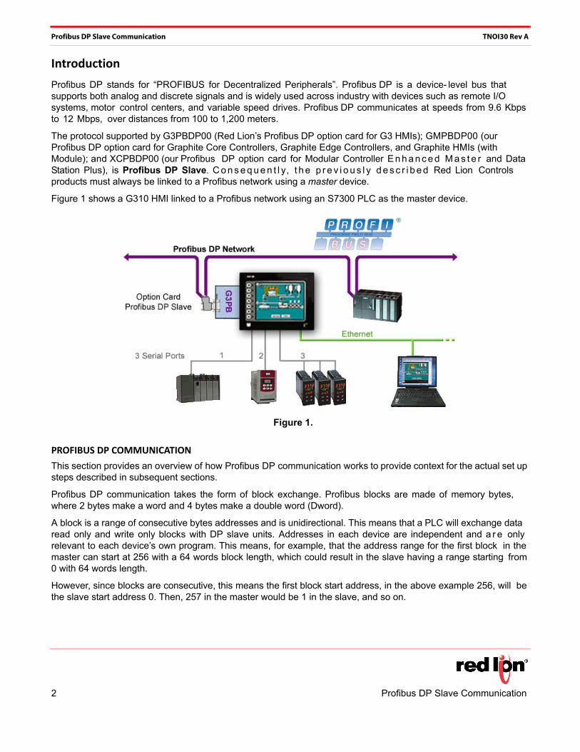
Profibus DP stands for “PROFIBUS for Decentralized Peripherals”. Profibus DP is a device- level bus that supports both analog and discrete signals and is widely used across industry with devices such as remote I/O systems, motor control centers, and variable speed drives. Profibus DP communicates at speeds from 9.6 Kbps to 12 Mbps, over distances from 100 to 1,200 meters.
The protocol supported by G3PBDP00 (Red Lion’s Profibus DP option card for G3 HMIs); GMPBDP00 (our Profibus DP option card for Graphite Core Controllers, Graphite Edge Controllers, and Graphite HMIs (with Module); and XCPBDP00 (our Profibus DP option card for Modular Controller E n h a n c e d M a s t e r and Data Station Plus), is Profibus DP Slave. C o n s e q u e n t l y, t h e p r e v i o u s l y d e s c r i b e d Red Lion Controls products must always be linked to a Profibus network using a master device.
Figure 1 shows a G310 HMI linked to a Profibus network using an S7300 PLC as the master device.
Figure 1.
PROFIBUS DP COMMUNICATION
This section provides an overview of how Profibus DP communication works to provide context for the actual set up steps described in subsequent sections.
Profibus DP communication takes the form of block exchange. Profibus blocks are made of memory bytes, where 2 bytes make a word and 4 bytes make a double word (Dword).
A block is a range of consecutive bytes addresses and is unidirectional. This means that a PLC will exchange data read only and write only blocks with DP slave units. Addresses in each device are independent and a r e only relevant to each device’s own program. This means, for example, that the address range for the first block in the master can start at 256 with a 64 words block length, which could result in the slave having a range starting from 0 with 64 words length.
However, since blocks are consecutive, this means the first block start address, in the above example 256, will be the slave start address 0. Then, 257 in the master would be 1 in the slave, and so on.
2 Profibus DP Slave Communication
Profibus DP Slave Communication TNOI30 Rev A
Blocks length can be defined in bytes, words, or Dwords. Since start addresses between the master and the slave can be different, one could give its start address and length in bytes, and the other in words or Dwords. To illustrate that, consider the following example:
The master start address is byte 256, with a 64 words block length.
• This results in a range from byte 256 up to byte 383.
The slave start address is word 0, with a 64 words block length.
• This results in a range from word 0 to word 63.
Figure 2 illustrates this exchange.
Figure 2.
NOTES: 1 . The Input block is independent from the Output block. Although the address range is the same, the data we are looking at are different.
2 . F ig u re 2 has no connection with the Input Block and Output Block used in Crimson. The terminology used in the tags configuration is from the PLC point of view (i.e., DP Master). Refer to the section Crimson Setup for more informa-tion.
Profibus DP Slave Communication 3
Profibus DP Slave Communication TNOI30 Rev A
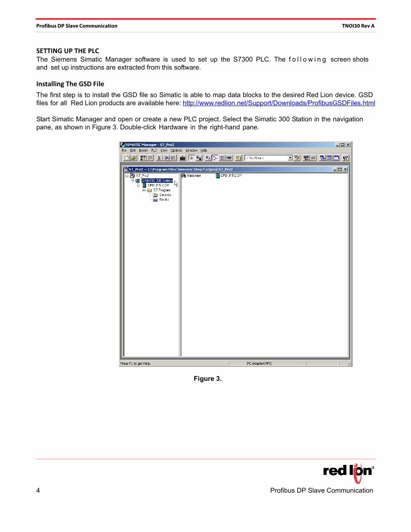
SETTING UP THE PLCThe Siemens Simatic Manager software is used to set up the S7300 PLC. The f o l l o w i n g screen shots and set up instructions are extracted from this software.
Installing The GSD File
The first step is to install the GSD file so Simatic is able to map data blocks to the desired Red Lion device. GSD files for all Red Lion products are available here: http://www.redlion.net/Support/Downloads/ProfibusGSDFiles.html
Start Simatic Manager and open or create a new PLC project. Select the Simatic 300 Station in the navigation pane, as shown in Figure 3. Double-click Hardware in the right-hand pane.
This starts HWConfig, where most of the work is done, and displays the current PLC hardware configuration. Close this configuration (not HWConfig) and choose Options>Install GSD File, as shown in Figure 4.
Figure 4.
Profibus DP Slave Communication 5
Profibus DP Slave Communication TNOI30 Rev A
Click Browse to specify the folder where the GSD file previously downloaded is located, select the file and click the Install button, as shown in Figure 5.
Once the GSD file successfully installs, the PLC hardware setup can be opened again by going to Station and selecting the latest opened file; which should be number 1.
If this is a new project, configure your PLC with the correct modules.
Figure 5.
6 Profibus DP Slave Communication
Profibus DP Slave Communication TNOI30 Rev A
Setting‐Up The Profibus Network.
The following steps detail how to set up the Profibus DP network. Skip these steps if your PLC application is already connected to a Profibus DP network.
In the floating window that represents the PLC, double click the DP field to open the properties window, as shown in Figure 6.
Figure 6.
Profibus DP Slave Communication 7
Profibus DP Slave Communication TNOI30 Rev A
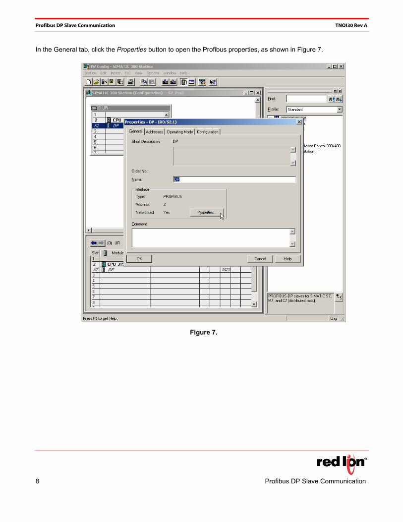
In the General tab, click the Properties button to open the Profibus properties, as shown in Figure 7.
Figure 7.
8 Profibus DP Slave Communication
Profibus DP Slave Communication TNOI30 Rev A
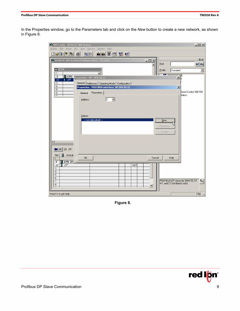
In the Properties window, go to the Parameters tab and click on the New button to create a new network, as shown in Figure 8.
Figure 8.
Profibus DP Slave Communication 9
Profibus DP Slave Communication TNOI30 Rev A
Then select the Network Settings tab and choose the Transmission Rate that fits the application. In this example, it will be 12 Mbps. The specified profile should be DP, as shown in Figure 9.
Figure 9.
10 Profibus DP Slave Communication
Profibus DP Slave Communication TNOI30 Rev A
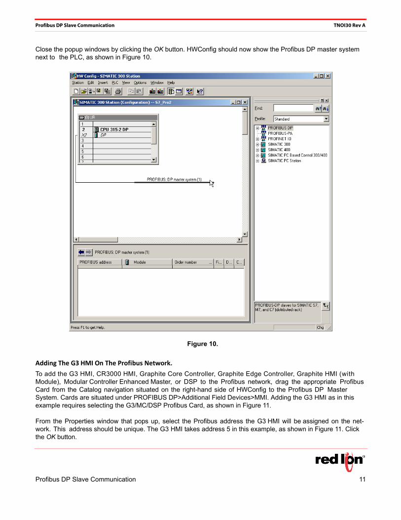
Close the popup windows by clicking the OK button. HWConfig should now show the Profibus DP master system next to the PLC, as shown in Figure 10.
Figure 10.
Adding The G3 HMI On The Profibus Network.
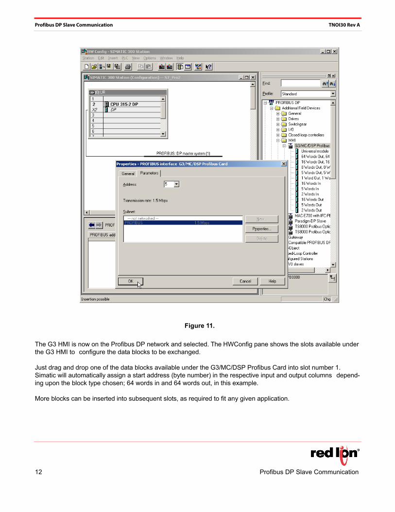
To add the G3 HMI, CR3000 HMI, Graphite Core Controller, Graphite Edge Controller, Graphite HMI (with Module), Modular Controller Enhanced Master, or DSP to the Profibus network, drag the appropriate Profibus Card from the Catalog navigation situated on the right-hand side of HWConfig to the Profibus DP Master System. Cards are situated under PROFIBUS DP>Additional Field Devices>MMI. Adding the G3 HMI as in this example requires selecting the G3/MC/DSP Profibus Card, as shown in Figure 11.
From the Properties window that pops up, select the Profibus address the G3 HMI will be assigned on the net-work. This address should be unique. The G3 HMI takes address 5 in this example, as shown in Figure 11. Click the OK button.
Profibus DP Slave Communication 11
Profibus DP Slave Communication TNOI30 Rev A
Figure 11.
The G3 HMI is now on the Profibus DP network and selected. The HWConfig pane shows the slots available under the G3 HMI to configure the data blocks to be exchanged.
Just drag and drop one of the data blocks available under the G3/MC/DSP Profibus Card into slot number 1. Simatic will automatically assign a start address (byte number) in the respective input and output columns depend-ing upon the block type chosen; 64 words in and 64 words out, in this example.
More blocks can be inserted into subsequent slots, as required to fit any given application.
12 Profibus DP Slave Communication
Profibus DP Slave Communication TNOI30 Rev A
Figure 12 shows an example with a 16 word input block in slot 2, and a 5 word output block in slot 3. Addresses are assigned automatically but can be edited by the user.
NOTE: If the starting address for a block in slot 2 or above changes and creates a gap in the address range, it will not affect the G3 HMI blocks, as all data are consecutive. It is however advisable to keep the addresses consecutive to facilitate development.
Figure 12.
Save the configuration and download it to the PLC.
NOTES:
1) The maximum number of input bytes allowed is 244. 2) The maximum number of output bytes allowed is 244. 3) The maximum number of bytes overall is 436
Profibus DP Slave Communication 13
Profibus DP Slave Communication TNOI30 Rev A
CRIMSON SETUP
Once the PLC is set up, the G3 HMI can be programmed to fit its configuration.
NOTE: For a G3 HMI, CR3000 HMI, Graphite Core Controller, Graphite Edge Controller, Graphite HMI (with Module), Modular Controller Enhanced Master, or DSP (Data Station Plus) to communi-cate on Profibus DP, a Profibus Option card must be fitted in the unit. Refer to the device man-ual to find the proper option card and installation procedure.
Setting‐Up The Profibus Communication
Enter the Communications module and select G3. On the right-hand pane, click the Pick button to select the Option card. Select Profibus Option Card and click the OK button, as shown in Figure 13. The option card appears in the communication tree. Select the Profibus Interface and click the OK button to select a driver.
Figure 13.
14 Profibus DP Slave Communication
Profibus DP Slave Communication TNOI30 Rev A
Click OK to pick the Profibus DP Slave driver, as shown in Figure 14.; Crimson now displays the driver settings where the Station Address can be changed. This address is the G3 HMI address on the Profibus network. In our example, this address is 5 (as previously set up in the PLC).
NOTE: There are no Baud Rate settings, as the Profibus option card detects the transmission rate automatically.
Figure 14.
Profibus DP Slave Communication 15
Profibus DP Slave Communication TNOI30 Rev A
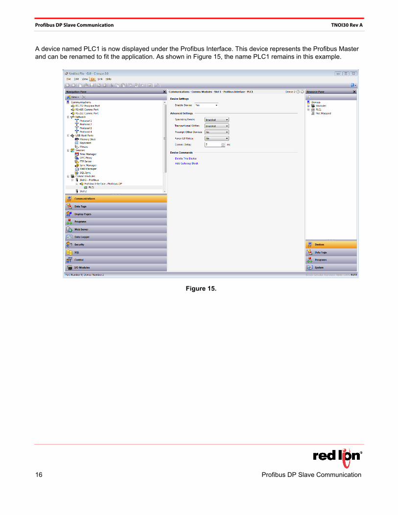
A device named PLC1 is now displayed under the Profibus Interface. This device represents the Profibus Master and can be renamed to fit the application. As shown in Figure 15, the name PLC1 remains in this example.
Figure 15.
16 Profibus DP Slave Communication
Profibus DP Slave Communication TNOI30 Rev A
Setting‐Up Tags
Once the communication is set up, tags can be created to access the PLC blocks. This is where the s teps p rev ious ly comp le ted within the section PROFIBUS DP COMMUNICATION, are important.
First, create a tag that corresponds to the data type required. In this example Numeric Tag is selected, as shown in Figure 16.
Figure 16.
Profibus DP Slave Communication 17
Profibus DP Slave Communication TNOI30 Rev A
Select the variable Tag1 (can be renamed later). Then, click on Internal next to Source on the right-hand pane, and select PLC1, which is the Profibus Master as shown in Figure 17.
Figure 17.
18 Profibus DP Slave Communication
Profibus DP Slave Communication TNOI30 Rev A
A popup window is displayed; select the Block Type required. Two choices are available:
• Input Block: The terminology input is from the Siemens perspective. Therefore, this will be a block the G3 HMI will write to. Any tag mapped to an input block has to be set up as Write Only.
• Output Block: The terminology output is from the Siemens perspective. Therefore this will be a block the G3 HMI will read from. Any tag mapped to an output block has to be set up as Read Only.
Select the Data Offset, which points the address to read or write in the block.
Select the Data Type to read or write. This defines how many bytes to access in the block to get the correct data.
In the example shown in Figure 18, the following are specified: Block Type as Output Block; Data Offset as 0 (which points to 256 in the PLC); and Data Type as Word.
Figure 18.
Profibus DP Slave Communication 19
Profibus DP Slave Communication TNOI30 Rev A
NOTE: Since the output block is a reading block from the G3 HMI perspective, this variable should be set up as Read Only, as shown in Figure 19. The same rule applies if the block is an input block; it should be set up as Write Only.
To avoid mistakes, the Access: field displays Read Only or Write Only for output or input block, respectively.
Figure 19.
20 Profibus DP Slave Communication
Profibus DP Slave Communication TNOI30 Rev A
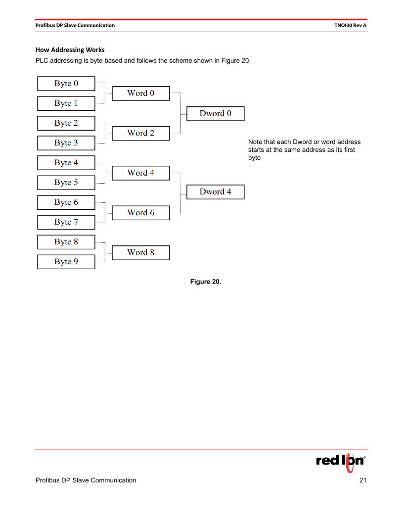
How Addressing Works
PLC addressing is byte-based and follows the scheme shown in Figure 20.
Figure 20.
Note that each Dword or word address starts at the same address as its first byte
Profibus DP Slave Communication 21
Profibus DP Slave Communication TNOI30 Rev A
However, G3 HMI addressing is different and follows the scheme shown in Figure 21.
Figure 21.
This means that the address number will be different when accessing words or Dwords in the G3 HMI data tags, than when access ing them in the Siemens PLC. These differences are detailed in the following table, which l is ts the address relationships for integer tags mapped as words in the G3 HMI
Siemens PLC G3 HMI
Block Type Input (Bytes) Output (Bytes) Input (Words) Output (Words)
64 words in, 64 words out 256…383 256…383 0…63 0…63
16 words in 384…415 ‐ 64…79 ‐
5 words out ‐ 384…393 ‐ 64…68
Here Dword or word addresses follow the normal numeric increment and are not directly related to the word or bytes of which they are composed.
22 Profibus DP Slave Communication
Profibus DP Slave Communication TNOI30 Rev A
Useful Formulas
The following formula can be used to find the byte number from a word address:
ByteAddress = PLCOffset + (WordAddress x 2)
Where:
- ByteAddress is the address we are looking for in the PLC
- PLCOffset is the first byte number in the complete block mapping in the PLC, here 256
- WordAddress is the address mapped in the G3 HMI
So, for example, word 77 in the G3 HMI, would start at byte 410 in the PLC, and would be composed of byte 410 and 411.
The following formula can be used to find the byte number from a Dword address:
ByteAddress = PLCOffset + (DWordAddress x 4)
Where:
- ByteAddress is the address we are looking for in the PLC
- PLCOffset is the first byte number in the complete block mapping in the PLC, here 256
- DwordAddress is the address mapped in the G3 HMI
So, for example, Dword 14 in the G3 HMI, would start at byte 312 in the PLC, and would be composed of byte 312, 313, 314, and 315.
NOTE: For the formula to work, all blocks in the PLC Profibus configuration for the G3 HMI must be consecutive, as shown in Figure 11.
Disclaimer
It is the customer's responsibility to review the advice provided herein and its applicability to the system. Red Lion makes no representation about specific knowledge of the customer's system or the specific performance of the system. Red Lion is not responsible for any damage to equipment or connected systems. The use of this document is at your own risk. Red Lion standard product warranty applies.
Red Lion Technical Support
If you have any questions or trouble contact Red Lion Technical Support by emailing [email protected] or calling 1-877-432-9908.
For more information: http://www.redlion.net/support/policies-statements/warranty-statement


![PROFIBUS DP bus interface, PROFIBUS DP [BU 2700]...Sicherheit/PROFIBUS DP [BU 2700]/Bestimmungsgemäße Ver wendung PROFIBUS DP @ 8\mod_1461835577600_388.docx @ 2249429 @ 2 @ 1 2.1](https://static.documents.pub/doc/80x56/60b54c574bd00c04b50e633d/profibus-dp-bus-interface-profibus-dp-bu-2700-sicherheitprofibus-dp-bu.jpg)


