Operator Interface Unit for GE Fanuc GENIUS TM and Universal Automation FloPro TM User Manual Horner APG GENIUS is a trademark of GE Fanuc Automation, North America, Inc. FloPro is a trademark of Universal Automation 09 FEB 1999 MAN0102-04
Transcript
Operator Interface Unitfor GE Fanuc GENIUSTM
and Universal Automation FloProTM
User Manual
Horner APG
GENIUS is a trademark of GE Fanuc Automation, North America, Inc.FloPro is a trademark of Universal Automation
09 FEB 1999 MAN0102-04
MODEL NUMBER: H E 6 9 3 O I U 9 1 0
SERIAL NUMBER:
WARRANTY REGISTRATION FORM
Please fill out this form and return it to Horner Electric. This information is vital to Horner Electric,should warranty service be required. This document is also used to keep you informed of newproduct enhancements, software revisions and documentation updates.
IT IS IN YOUR BEST INTEREST TO FILL OUT AND RETURN THIS FORM!
Date of purchase:
Name:
Title:
Company :
Department/Div is ion:
Street Address:
City/State/Zip:
Area Code/Phone Number:
Purchased from (Distributor):
Please indicate the type of application where this product is to be used, check all that apply:
Chemical processingDemo equipmentEduca t i onEnergy managementFood processingMilitaryProduct assembly/testing produc t :Waste processingOther (specify)
FOR NORTH AMERICA ONLY!
STAMP
F O L D
F O L D
Horner APGAPG - Controls Division
640 N. Sherman Drive StreetIndianapolis, Indiana 46201-3899
ATTN: Warranty Registration Department
P R E F A C E Page iv
P R E F A C E
This manual explains how to use the Horner APG Operator Interface Unit for use with the GEFanuc Genius I/O Network and Universal Automation's FloPro.
Copyright (C) 1992 Horner APG, LLC., 640 N. Sherman Drive, Indianapolis Indiana 46201-3899. All rights reserved. No part of this publication may be reproduced, transmitted,transcribed, stored in a retrieval system, or translated into any language or computer language,in any form by any means, electronic, mechanical, magnetic, optical, chemical, manual orotherwise, without the prior agreement and written permission of Horner Electric, Inc.
Information in this document is subject to change without notice and does not represent acommitment on the part of Horner APG, LLC.
Genius, Logicmaster and Series 90 are trademarks of GE Fanuc Automation North AmericaInc .
FloPro is a trademark of Universal Automation.
Page v P R E F A C E
LIMITED WARRANTY AND LIMITATION OF LIABILITY
Horner APG, LLC. Inc. ("HE") warrants to the original purchaser that the Operator Interface Unitmanufactured by HE is free from defects in material and workmanship under normal use andservice. The obligation of HE under this warranty shall be limited to the repair or exchange of anypart or parts which may prove defective under normal use and service within two years from thedate of manufacture or eighteen (18) months from the date of installation by the originalpurchaser whichever occurs first, such defect to be disclosed to the satisfaction of HE afterexamination by HE of the allegedly defective part or parts. THIS WARRANTY IS EXPRESSLYIN LIEU OF ALL OTHER WARRANTIES EXPRESSED OR IMPLIED INCLUDING THEWARRANTIES OF MERCHANTABILITY AND FITNESS FOR USE AND OF ALL OTHEROBLIGATIONS OR LIABILITIES AND HE NEITHER ASSUMES, NOR AUTHORIZES ANYOTHER PERSON TO ASSUME FOR HE, ANY OTHER LIABILITY IN CONNECTION WITHTHE SALE OF THIS OPERATOR INTERFACE UNIT. THIS WARRANTY SHALL NOT APPLYTO THIS OPERATOR INTERFACE UNIT OR ANY PART THEREOF WHICH HAS BEENSUBJECT TO ACCIDENT, NEGLIGENCE, ALTERATION, ABUSE, OR MISUSE. HE MAKESNO WARRANTY WHATSOEVER IN RESPECT TO ACCESSORIES OR PARTS NOT SUP-PLIED BY HE. THE TERM "ORIGINAL PURCHASER", AS USED IN THIS WARRANTY,SHALL BE DEEMED TO MEAN THAT PERSON FOR WHOM THE OPERATOR INTERFACEUNIT IS ORIGINALLY INSTALLED. THIS WARRANTY SHALL APPLY ONLY WITHIN THEBOUNDARIES OF THE CONTINENTAL UNITED STATES.
In no event, whether as a result of breach of contract, warranty, tort (including negligence) orotherwise, shall HE or its suppliers be liable of any special, consequential, incidental or penaldamages including, but not limited to, loss of profit or revenues, loss of use of the products orany associated equipment, damage to associated equipment, cost of capital, cost of substituteproducts, facilit ies, services or replacement power, down time costs, or claims of originalpurchaser's customers for such damages.
To obtain warranty service, return the product to your distributor after obtaining a "ReturnMaterial Authorization". Include a description of the problem, proof of purchase, post paid,insured and in a suitable package.
P R E F A C E Page vi
ABOUT THE PROGRAM EXAMPLES
The example programs and program segments in this manual are included solely for illustrativepurposes. Due to the many variables and requirements associated with any particularinstallation, Horner Electric cannot assume responsibility or liablity for actual use based on theexamples and diagrams. It is the sole responsibility of the system designer utilizing this softwareto appropriately design the end system, to appropriately integrate the Operator Interface Unitand to make safety provisions for the end equipment as is usual and customary in industrialapplications as defined in any codes or standards which apply.
Page vii P R E F A C E
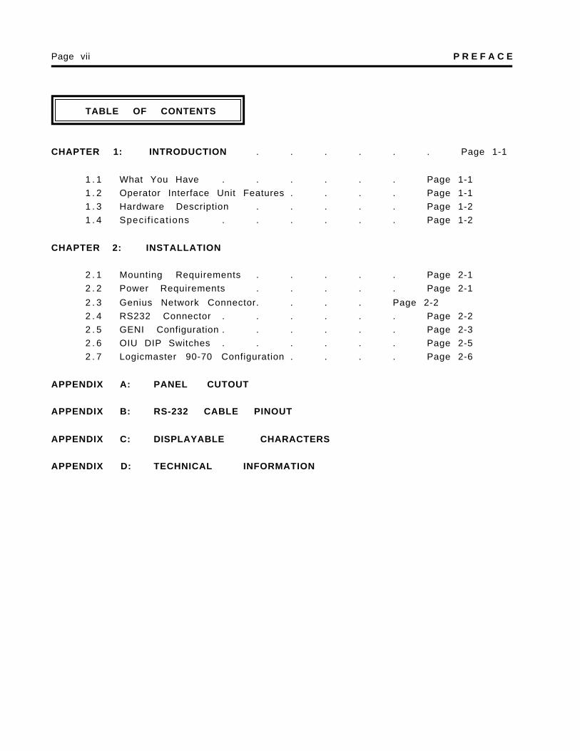
TABLE OF CONTENTS
CHAPTER 1: INTRODUCTION . . . . . . Page 1-1
1 . 1 What You Have . . . . . . Page 1-11 . 2 Operator Interface Unit Features . . . . Page 1-11 . 3 Hardware Description . . . . . Page 1-21 . 4 Speci f icat ions . . . . . . Page 1-2
Congratulations on your purchase of the Operator Interface Unit. This unit has been de-signed using state-of-the-art electronic components and incorporates a sophisticated firm-ware package that gives the Original Equipment Manufacturer (OEM) the ability to utilize thisunit with the powerful FloPro Development Package from Universal Automation.
1 . 1 What You Have
The Operator Interface Unit (OIU) comes complete with the following items:
A . Assembled OIU module and mounting hardware, including theGenius TM Network Interface board (GENI).
B . Aluminum Rear Cover for OIU (Available January, 1993).
C. This manual.
1 . 2 Operator Interface Unit Features
The Horner Operator Interface Unit provides the following features:
A . Gasketed NEMA 4-12 panel with a rugged LexanTM overlay, mounting hard ware included.
B . Four line by 20 character dot-matrix vacuum-fluorescent display.
C. Tactile feel keypad with numeric support plus special function keys..
D . Integrated Genius Network Interface board (GENI) for communications onGE Fanuc's Genius Distributed I/O Network.
.E . Acts as a high-performance FloPro Remote Message Unit by communicating
over a high speed I/O network instead of a slower, serial based connection.
F . Standard 9-pin RS232 communications port, for connection to a GE Fanuc PowerMate Motion Controller.
G . Optional Auxiliary RS232 communications port for communications with asecond GE Fanuc PowerMate Motion Controller.
1 . 3 Hardware Description
The Operator Interface Unit (HE693OIU910) consists of six main components, and oneoptional component. They are:
A ) Keypad / Mounting plate.
B ) Main Circuit Board.
C ) Vacuum Fluorescent Display Circuit Board.
D ) Power Supply Circuit Board.
E ) Genius Network Interface (GENI) Board.
F ) Aluminum Rear Cover.
G ) (Optional) Auxiliary RS232 Circuit Board. (HE-BUS architecture).
The OIU is a microprocessor-based high-performance communications device. The core ofthe Main Circuit Board is the Intel 80C152 microprocessor running at 11.0592 MegaHertz.The “firmware” memory is contained in a 27C256 EPROM device. The Main Circuit Board isalso equipped with 32K bytes of high-speed static RAM memory. There is no retainedmemory on the unit. The OIU incorporates a Genius Network Interface board (GENI) thatprovides the link to the Genius network. The initial OIU power supply accepts a wide ACinput range. A standard 24VDC power supply will be standard after January 1, 1993.
1 . 4 S p e c i f i c a t i o n s
Mounting Requirements: Panel Mounting, NEMA 4-12
C o m m u n i c a t i o n s : Genius Network Interface (GENI)
Additional Communications: Standard RS232 for PowerMate.Optional Auxiliary RS232 for PowerMate
Power Requirements:DC Version 12.5-32 VDC, 14 Watts power max.
Operating Environment: 0 to 60° C. (32 to 140° F).0 to 95% humidity (non-condesing).
The OIU is designed for permanent panel mounting. To install the OIU:
A . Cut the host panel as described by the drawing in Appendix A.
B . Make sure all terminal connectors are removed from the OIU.
C. Remove the aluminum back cover (if installed), by removing the screwssecuring it to the OIU. Carefully lift the cover off the rear of the OIU a fewinches, disconnecting the power terminal from the power supply circuit board.The rear cover should now be completely free of the OIU.
D . Remove the six #6-32 hex nuts and washers from the outer mounting studson the rear of the OIU panel.
E . Insert the OIU module through the front panel cutout. The gasket materialshould lie between the host panel and the OIU panel.
F . Install the six #6-32 nuts and lock-washers on the six mounting studs of theOIU. Tighten these nuts until the gasket material forms a tight seal, do not
overt ighten.
G . Re-install the rear cover (if present). Be sure to re-connect the powerterminal to the power supply circuit board. Re-connect all terminalconnectors (power and Genius network terminals). This completes the me-
chanical installation of the OIU module.
2.2 Power Requirements
The OIU power supply requires a DC supply voltage between 12 and 32 volts. A maximumof 14 watts will be drawn by the OIU. The OIU power supply features a 3-position,removeable terminal block. See Figure 2-1 for connector location. The pinout for thisconnector is shown below in Table 2-1.
CHAPTER 2:INSTALLATION Page 2-1
Table 2-1. DC connector pinout
Pin Signal
1 Frame Ground
2 DC Common
3 +12-32VDC
Figure 2-1. Connectors
2 . 3 Genius Network Connector
The OIU is also equipped with a 4-pin Genius bus connector. The mating connector pro-vides screw terminals for each circuit. The pinout for this connector is as follows:
Table 2-2. Genius Network Connector Pinout
2 . 4 RS232 Connector(s)
The 9-pin “D” connectors on the main circuit board and optional auxiliary port provide RS232interfaces to two GE Fanuc PowerMate Motion Controllers. The OIU-to-PowerMate cablepinout is shown in Appendix B. For more technical information on the communicationsbetween the OIU and the PowerMate, see Appendix D.
RS-232 ConnectorD B - 9 S
Genius BusC o n n e c t o r
P o w e rC o n n e c t o r(on lowerb o a r d )
P i n S i g n a l
1 Serial 1
2 Serial 2
3 Shield Out
4 Shield In
Page 2-2 CHAPTER 2: INSTALLATION
Optional RS-232C o n n e c t o rD B - 9 S
2 . 5 GENI Configuration
The GENI board (located on the rear of the OIU module) is equipped with a bank of 8 “DIP”switches. DO NOT CONFUSE THIS DIP SWITCH WITH THE 6-POSITION DIP SWITCHON THE MAIN CIRCUIT BOARD DESCRIBED LATER. These switches are used to config-ure the Genuis “bus” address or “Device Number” for the OIU module, and to set themodule’s Genius baud rate.
Each device on the Genius network must have a unique “Device Number” (0 to 31). The OIUmay be configured for any device number, however the following conventions should befollowed when chosing the device number for the OIU:
A . The bus controller is usually configured as device number 31.B . The redundant bus controller (if any) is usually configured as device number
30 .C. The Hand-Held monitor is usually configured as device number 0.
When shipped from the factory, the OIU dip switches are configured for device number 29,and for communication baud rate of 153.6K standard. Multiple OIUs may reside on thenetwork, provided that they have unique device numbers. Available dip switch settings areillustrated in Figure 2-2.
CHAPTER 2:INSTALLATION Page 2-3
Figure 2-2 . GENI DIP Switch Assignments
Page 2-4 CHAPTER 2: INSTALLATION
8 7 6 5 4 3 2 1
5 4 3 2 1 a d d r e s 5 4 3 2 1 a d d r e s
C L O S D C L O S D C L O S D C L O S D C L O S D 0 O P E N C L O S D C L O S D C L O S D C L O S D 1 6
C L O S D C L O S D C L O S D C L O S D O P E N 1 O P E N C L O S D C L O S D C L O S D O P E N 1 7
C L O S D C L O S D C L O S D O P E N C L O S D 2 O P E N C L O S D C L O S D O P E N C L O S D 1 8
C L O S D C L O S D C L O S D O P E N O P E N 3 O P E N C L O S D C L O S D O P E N O P E N 1 9
C L O S D C L O S D O P E N C L O S D C L O S D 4 O P E N C L O S D O P E N C L O S D C L O S D 2 0
C L O S D C L O S D O P E N C L O S D O P E N 5 O P E N C L O S D O P E N C L O S D O P E N 2 1
C L O S D C L O S D O P E N O P E N C L O S D 6 O P E N C L O S D O P E N O P E N C L O S D 2 2
C L O S D C L O S D O P E N O P E N O P E N 7 O P E N C L O S D O P E N O P E N O P E N 2 3
C L O S D O P E N C L O S D C L O S D C L O S D 8 O P E N O P E N C L O S D C L O S D C L O S D 2 4
C L O S D O P E N C L O S D C L O S D O P E N 9 O P E N O P E N C L O S D C L O S D O P E N 2 5
C L O S D O P E N C L O S D O P E N C L O S D 1 0 O P E N O P E N C L O S D O P E N C L O S D 2 6
C L O S D O P E N C L O S D O P E N O P E N 1 1 O P E N O P E N C L O S D O P E N O P E N 2 7
C L O S D O P E N O P E N C L O S D C L O S D 1 2 O P E N O P E N O P E N C L O S D C L O S D 2 8
C L O S D O P E N O P E N C L O S D O P E N 1 3 O P E N O P E N O P E N C L O S D O P E N 2 9
C L O S D O P E N O P E N O P E N C L O S D 1 4 O P E N O P E N O P E N O P E N C L O S D 3 0
C L O S D O P E N O P E N O P E N O P E N 1 5 O P E N O P E N O P E N O P E N O P E N 3 1
7 6 baud rate
C L O S D C L O S D 153.6K extended
C L O S D O P E N 3 8 . 4 K
O P E N C L O S D 7 6 . 8 K
O P E N O P E N 153.6K standard
ALWAYS OPEN
2 . 6 OIU DIP SwitchesThe MAIN circuit board is equipped with a bank of 6 “DIP” switches. These switches areaccessable by removal of the metal back cover. The user should never need to changethe default position(s). The default positions are indicated in BOLD below. Theseswitches are used to configure the following OIU options:
Always CLOSED
Always CLOSED
Always CLOSED
Firmware Size (CLOSED=64K, OPEN=32K)
Watchdog Enable (CLOSED=enable, OPEN=disable)
RS-232 Mode (CLOSED=normal, OPEN=test)
Figure 2-3 . MAIN board DIP Switch Assignments
2 . 7 Logicmaster 90-70 Configuration
The 90-70 Genius Bus Controller must be configured by Logicmaster to communicate withthe OIU. The proper settings are as follows:
GENI-based device *the proper bit memory typeConfig Mode: m a n u a l (%I, %M, %G, etc.) will beTo: (bit type memory)* determined by GE Fanuc andInput Length: 8 Universal Automation
2 . 8 FloPro Configuration
Consult documentation provided with Universal Automation FloPro for the configuration ofRemote Message Units (OIUs) in FloPro. Future editions of this manual may provide thisinformation for convenience.
CHAPTER 2: INSTALLATION Page 2-5
6 5 4 3 2 1
APPENDIX A: PANEL CUTOUT
The OIU module is designed for panel mounting. The drawing below illustrates the panel cutoutrequired for OIU module mounting. All dimensions shown in brackets are in millimeters, andthose shown without brackets are in inches.
APPENDIX B: RS-232 CABLE PINOUT
Following is the wiring diagram for the RS-232 cable for communications between the OIU910serial port and the PowerMate Motion Controller Serial Port..
APPENDIX C: DISPLAYABLE CHARACTERS
The following chart lists the characters which are displayable by the 4-line by 20 charactervacuum fluorescent display. The ASCII code for each character is indicated by the row (firstdigit 0-F in hex) and the column (second digit 0-F in hex) in which the character resides. Forinstance, the character "q" is represented by ASCII code 17H.
N o t e : Characters with second digit "E" (column E above) are Russian Letters