43
MET ONE 237H PORTABLE AIRBORNE PARTICLE COUNTER Operator Manual
Met One 237H POrtable airbOrne Particle cOunter
Operator Manual
Met One 237HPOrtable airbOrne Particle cOunter
Operator Manual

237H - Table of Contents 3 of 40R
PS
- 21
Nov
embe
r 200
7 - E
ditio
n 2-
d5
Met One Operator Manual
Table of Contents
1 Manual Overview1.1 About This Manual ................................................................................... 51.2 Safety....................................................................................................... 5
1 Introduction1.1 Accessories............................................................................................ 101.2 Unpacking and Initial Inspection ............................................................ 101.3 237H Setup ............................................................................................ 11
1.3.1 Initial Power Turn-On................................................................ 111.4 Counting for the First Time .................................................................... 12
2 Front Panel Overview
3 237H Operation3.1 Time and Date ....................................................................................... 173.2 Period and Hold Time ............................................................................ 173.3 Count Alarm Limits................................................................................. 183.4 Concentration (CONCEN) Mode............................................................ 183.5 Audible (BEEP) Mode ............................................................................ 193.6 Clear Rotating Buffer (BUF)................................................................... 193.7 Setting Number of Count Cycles (CYC)................................................. 193.8 Changing Location Number (Loc) .......................................................... 203.9 Turning Beeper On or Off (AFb) ............................................................ 203.10 Changing Volume Units for Concentration Mode (UOL)........................ 203.11 Setting Baud Rate (bd) .......................................................................... 203.12 Changing Printer Options....................................................................... 21
4 Using Options and Accessories4.1 Setting up an External Printer ................................................................ 234.2 Environmental Probe ............................................................................. 23
5 Serial Port Protocol and Commands5.1 Serial Cables.......................................................................................... 255.2 Communication Protocol........................................................................ 265.3 Commands............................................................................................. 275.4 Data ....................................................................................................... 28
Appendix A: SpecificationsA.1 Accessories............................................................................................ 30
4 of 40 Table of Contents - 237H
RP
S - 2
1 N
ovem
ber 2
007
- Edi
tion
2-d5
Operator Manual Met One
Appendix B: Technical DataB.1 Recharging the Battery Pack ................................................................. 31B.2 Resetting the Counter ............................................................................ 31
Appendix C: Declaration of Conformity
Appendix D: Service ProceduresD.1 Return Procedures................................................................................. 35D.2 Technical Support Information ............................................................... 35
237H - Manual Overview 5 of 40R
PS
- 21
Nov
embe
r 200
7 - E
ditio
n 2-
d5
Met One Operator Manual
1 Manual Overview
1.1 About This Manual
The information in this manual has been carefully checked and is believed to be accurate. However, Hach Ultra assumes no responsibility for any inaccuracies that may be contained in this manual. In no event will Hach Ultra be liable for direct, indirect, special, incidental, or consequential damages resulting from any defect or omission in this manual, even if advised of the possibility of such damages. In the interest of continued product development, Hach Ultra reserves the right to make improvements in this manual and the products it describes at any time, without notice or obligation.
Published in the United States of America
Hach Ultra P/N: 701101 Edition 2-d5, 21 November 2007
Copyright © 1993-2007 by Hach Ultra Analytics, Inc.
All rights reserved. No part of the contents of this manual may be reproduced or transmitted in any form or by any means without the written permission of Hach Ultra.
1.2 Safety
WARNINGA warning is used to indicate a condition which, if not met, could cause serious personal injury and/or death. Do not move beyond a warning until all conditions have been met.
CAUTION:A caution is used to indicate a condition which, if not met, could cause damage to the equipment. Do not move beyond a caution until all conditions have been met.
Note:A note is used to indicate important information or instructions that should be considered before operating the equipment.
General Safety Considerations• Read the 237H Airborne Particle Counter Operator Manual thoroughly before installing
or operating the instrument. Although the 237H is designed for rugged use, it is still an instrument that should be cared for and maintained as described in this manual. Following proper safety and handling instructions will promote accident free operation and prolong product life.
• For any questions regarding the 237H, contact Hach Ultra at 800.866.7889 or +1-541.472.6500.
• All service procedures should be conducted by properly trained service personnel.• Make sure the 237H Airborne Particle Counter is properly installed and all connections
are correctly installed before operation. All safety guidelines should be observed.• Follow all procedures in “Return Procedures” on page 35 before shipping a unit to a
service center for repair or re-calibration.
6 of 40 Manual Overview - 237H
RP
S - 2
1 N
ovem
ber 2
007
- Edi
tion
2-d5
Operator Manual Met One
WARNINGUse of controls or adjustments, or performance of procedures other than those specified herein may result in hazardous radiation exposure.
WARNINGOnly factory certified personnel should perform service of the 237H. Attempts by untrained personnel to disassemble, alter, modify or adjust the electronics and/or hydraulics may result in personal injury and damage to the 237H.
237H Airborne Particle Counter Warnings and CautionsThere are several classifications of Warnings defined as follows:
• Laser—pertaining to exposure to visible or invisible laser radiation • Electrostatic—pertaining to static hazards
Laser Safety InformationThis 237H particle counter contains a laser-based sensor that is a Class 1 product (as defined by 21 CFR, Subchapter J, of the Health and Safety Act of 1968) when used under normal operation and maintenance.
The manual contains no procedures for service of internal parts within this unit. Service should be performed only by factory-authorized personnel. The particle counter has been evaluated and tested in accordance with EN 61010-1:2001, “Safety Requirements For Electrical Equipment For Measurement, Control, and Laboratory Use” and IEC 60825-1, EN60825-1, “Safety of Laser Products.”
WARNINGThe use of controls, adjustments, or performance of procedures other than those specified within this manual may result in exposure to invisible (infrared) radiation that can quickly cause blindness.
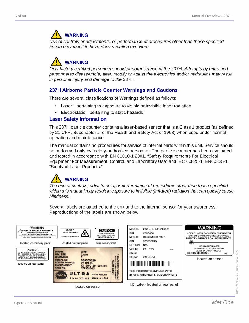
Several labels are attached to the unit and to the internal sensor for your awareness. Reproductions of the labels are shown below.
located on sensor
IEC60825-1/EN60825-1
I.D. Label - located on rear panel
located on sensor
IEC60825-1/EN60825-1
237H - Manual Overview 7 of 40R
PS
- 21
Nov
embe
r 200
7 - E
ditio
n 2-
d5
Met One Operator Manual
Additional safety information is contained in the “Particle Counters For Air" manual you also received. For further technical assistance, contact Hach Ultra at 800.866.7889 or +1-541.472.6500.
Electrostatic Safety InformationElectrostatic discharge (ESD) can damage or destroy electronic components. Therefore, all work inside the particle counter should be done at a static-safe work station. A static-safe work station can be created by doing the following:
• Use a grounded conductive table mat and resistor-isolated wrist-strap combination • Earth-ground all test instruments to prevent a buildup of static charge
WARNINGUsing a wrist strap without an insolation resistor will increase the severity of an electrical shock.
WarrantyHach Ultra warrants that this instrument will be free of defects in materials and workmanship for a period of one (1) year from the shipping date. If any instrument covered under this warranty proves defective during this period, Hach Ultra will, at its option, either repair the defective product without charge for parts and labor, or provide an equivalent replacement in exchange for the defective product.
To obtain service under this warranty, the customer must notify the nearest Hach Ultra service support center on or before the expiration of the warranty period and follow their instructions for return of the defective instrument. The customer is responsible for all costs associated with packaging and transporting the defective unit to the service support center, and must prepay all shipping charges. Hach Ultra will pay for return shipping if the shipment is to a location within the same country as the service support center.
This warranty shall not apply to any defect failure or damage caused by improper use or maintenance or by inadequate maintenance or care. This warranty shall not apply to damage resulting from attempts by personnel other than Hach Ultra representatives, or factory-authorized and trained personnel, to install, repair or service the instrument; to damage resulting from improper use or connection to incompatible equipment; or to instruments that have been modified or integrated with other products when the effect of such modification or integration materially increases the time or difficulty of servicing the instrument.
THIS WARRANTY IS GIVEN BY HACH ULTRA ANALYTICS, INC. WITH RESPECT TO THIS INSTRUMENT IN LIEU OF ANY OTHER WARRANTIES, EXPRESSED OR IMPLIED. HACH ULTRA ANALYTICS, INC. AND ITS VENDORS DISCLAIM ANY IMPLIED WARRANTIES OF MERCHANTABILITY OR FITNESS FOR A PARTICULAR NON-CONTRACTUAL PURPOSE. HACH ULTRA ANALYTICS, INC.’ RESPONSIBILITY TO REPAIR OR REPLACE DEFECTIVE PRODUCTS IS THE SOLE AND EXCLUSIVE REMEDY PROVIDED TO THE CUSTOMER FOR BREACH OF THIS WARRANTY. HACH ULTRA ANALYTICS, INC. AND ITS VENDORS WILL NOT BE LIABLE FOR ANY INDIRECT, SPECIAL, INCIDENTAL, OR CONSEQUENTIAL DAMAGES EVEN IF HACH ULTRA ANALYTICS, INC. OR ITS VENDORS HAS BEEN GIVEN ADVANCED NOTICE OF THE POSSIBILITY OF SUCH DAMAGES.
8 of 40 Manual Overview - 237H
RP
S - 2
1 N
ovem
ber 2
007
- Edi
tion
2-d5
Operator Manual Met One
Patents
Apparatus and products are manufactured and sold by Hach Ultra Analytics, Inc. under one or more of the following U.S. patents: 4,626,413; 4,666,860; 4,683,435; 4,868,127; 5,047,212; 5,260,663; 5,275,957; 5,334,940; 5,677,190 and equivalents in other countries where issued. Purchaser is granted a paid-up, non-exclusive license to practice under these patents for the useful life of this apparatus or product.
Revision History• Edition A, September 1993, Met One Corporation• Edition 2, May 2007, Hach Ultra Analytics, Inc.
237H - Introduction 9 of 40R
PS
- 21
Nov
embe
r 200
7 - E
ditio
n 2-
d5
Met One Operator Manual
1 Introduction
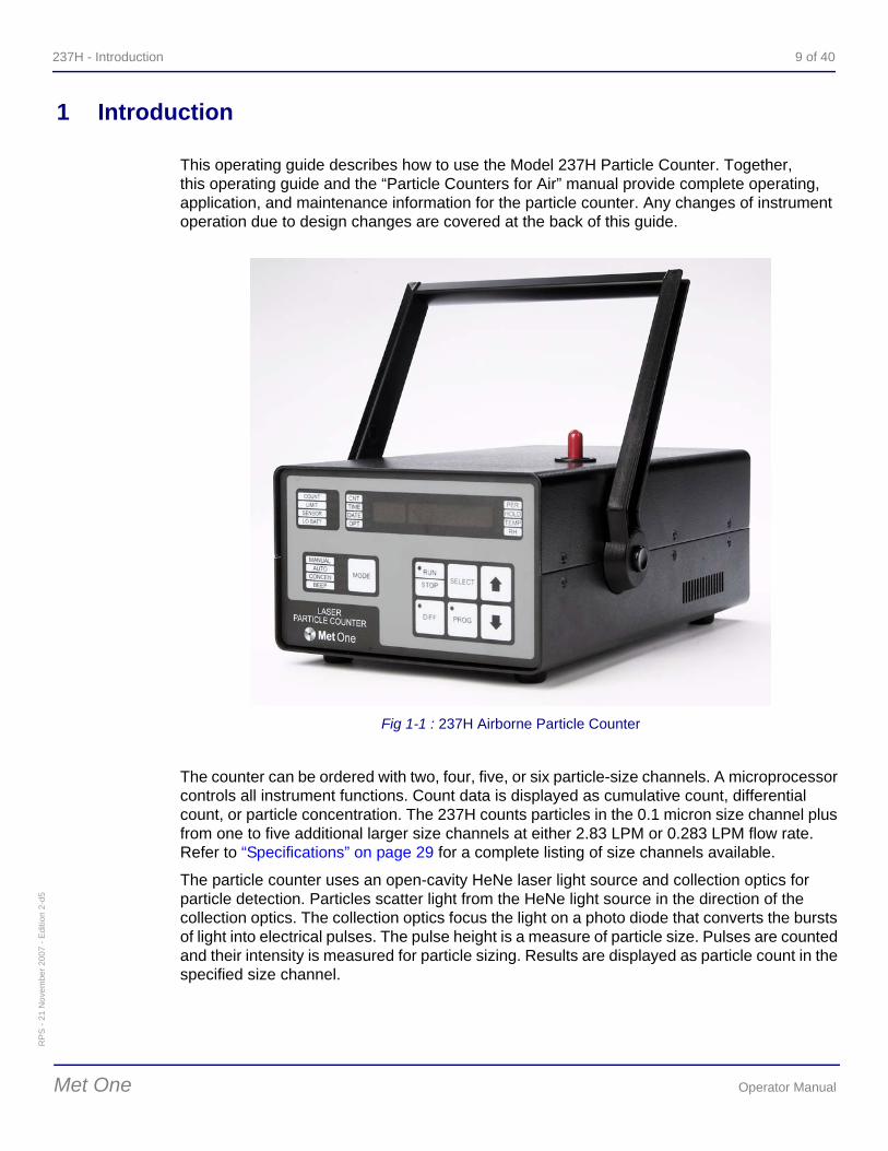
This operating guide describes how to use the Model 237H Particle Counter. Together, this operating guide and the “Particle Counters for Air” manual provide complete operating, application, and maintenance information for the particle counter. Any changes of instrument operation due to design changes are covered at the back of this guide.
The counter can be ordered with two, four, five, or six particle-size channels. A microprocessor controls all instrument functions. Count data is displayed as cumulative count, differential count, or particle concentration. The 237H counts particles in the 0.1 micron size channel plus from one to five additional larger size channels at either 2.83 LPM or 0.283 LPM flow rate. Refer to “Specifications” on page 29 for a complete listing of size channels available.
The particle counter uses an open-cavity HeNe laser light source and collection optics for particle detection. Particles scatter light from the HeNe light source in the direction of the collection optics. The collection optics focus the light on a photo diode that converts the bursts of light into electrical pulses. The pulse height is a measure of particle size. Pulses are counted and their intensity is measured for particle sizing. Results are displayed as particle count in the specified size channel.
Fig 1-1 : 237H Airborne Particle Counter
10 of 40 Introduction - 237H
RP
S - 2
1 N
ovem
ber 2
007
- Edi
tion
2-d5
Operator Manual Met One
1.1 Accessories
High Pressure Diffuser—connects to the sensor inlet tube. Permits direct sampling of pressurized air and inert gases (e.g., argon, nitrogen, helium) at pressures from 30 to 150 psi.
RH/Temp Probe—plugs into the counter rear panel. The probe monitors relative humidity (10% to 90%) and temperature (0 to 100 °F or -17 to +38°C, specify one). The results are displayed and printed.
RS-485 Converter—for conversion from RS-232 to RS-485 serial networking to a computer.
RS-485 Network Adapter—adapts 9-pin SERIAL I/O counter connector to 4-pin configuration.
Isokinetic Probe (provided with counter)—for use in unidirectional air flow to maximize correlation between counts and actual particle-size distribution. Can also be hand-held for spot location particle counting.
Purge Filter—attaches to sensor inlet; keeps external particles from contaminating sensor while purging sensor of internal particles.
Carrying Case—protects the counter during shipment and storage.
1.2 Unpacking and Initial Inspection
The particle counter is thoroughly inspected and tested at the factory and is ready for use upon receipt. When received, inspect the shipping carton for damage. If the carton is damaged, notify the carrier and save the carton for carrier and save the carton for carrier inspection. Inspect the counter for broken parts, scratches, dents, or other damage.
If the carton is not damaged, keep for reshipment. For example, reuse the carton when returning the counter for the annual factory calibration.
237H - Introduction 11 of 40R
PS
- 21
Nov
embe
r 200
7 - E
ditio
n 2-
d5
Met One Operator Manual
1.3 237H Setup
1.3.1 Initial Power Turn-On
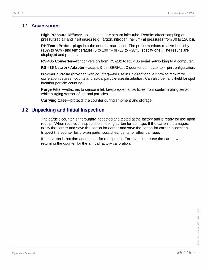
Before turning the power on, locate the counter in its working environment and perform an initial installation as follows:
1) If AC power is to be used, plug the AC adapter supplied with the 237H into facility power outlet; insert other end of adapter into rear panel connector marked POWER.
2) Remove the protective tubing from the inlet tube (see figure above). If using an isokinetic probe, connect probe to inlet tube.
3) Set ON/OFF (on rear panel) to ON. The counter will power up and check memory.4) If the RUN key light is on, press RUN/STOP.5) (This step loads default values and gives an audible tone.) Turn power off. Press and
hold MODE then turn power on. A beep will sound. Release MODE. The front panel displays should be as follows:
: on,dEF 507-1F: shows default values have been reloaded; gives EPROM part number and revision level (Note: the revision level letter may not match the letter shown in this manual).
6) Press Down to return to normal operation. The correct time of day and date at this time may be entered. If so, perform the “Time and Date” procedure that appears on following pages. When completed, the counter is ready for use.
Fig 1-2 : Turning Power On
12 of 40 Introduction - 237H
RP
S - 2
1 N
ovem
ber 2
007
- Edi
tion
2-d5
Operator Manual Met One
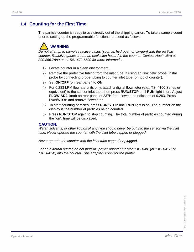
1.4 Counting for the First Time
The particle counter is ready to use directly out of the shipping carton. To take a sample count prior to setting up the programmable functions, proceed as follows:
WARNINGDo not attempt to sample reactive gases (such as hydrogen or oxygen) with the particle counter. Reactive gases create an explosion hazard in the counter. Contact Hach Ultra at 800.866.7889 or +1-541.472.6500 for more information.
1) Locate counter in a clean environment.2) Remove the protective tubing from the inlet tube. If using an isokinetic probe, install
probe by connecting probe tubing to counter inlet tube (on top of counter). 3) Set ON/OFF (on rear panel) to ON.4) For 0.283 LPM flowrate units only, attach a digital flowmeter (e.g., TSI 4100 Series or
equivalent) to the sensor inlet tube then press RUN/STOP until RUN light is on. Adjust FLOW ADJ. knob on rear panel of 237H for a flowmeter indication of 0.283. Press RUN/STOP and remove flowmeter.
5) To start counting particles, press RUN/STOP until RUN light is on. The number on the display is the number of particles being counted.
6) Press RUN/STOP again to stop counting. The total number of particles counted during the “on”. time will be displayed.
CAUTION:Water, solvents, or other liquids of any type should never be put into the sensor via the inlet tube. Never operate the counter with the inlet tube capped or plugged.
Never operate the counter with the inlet tube capped or plugged.
For an external printer, do not plug AC power adapter marked “DPU-40” (or "DPU-411" or “DPU-414”) into the counter. This adapter is only for the printer.
237H - Front Panel Overview 13 of 40R
PS
- 21
Nov
embe
r 200
7 - E
ditio
n 2-
d5
Met One Operator Manual
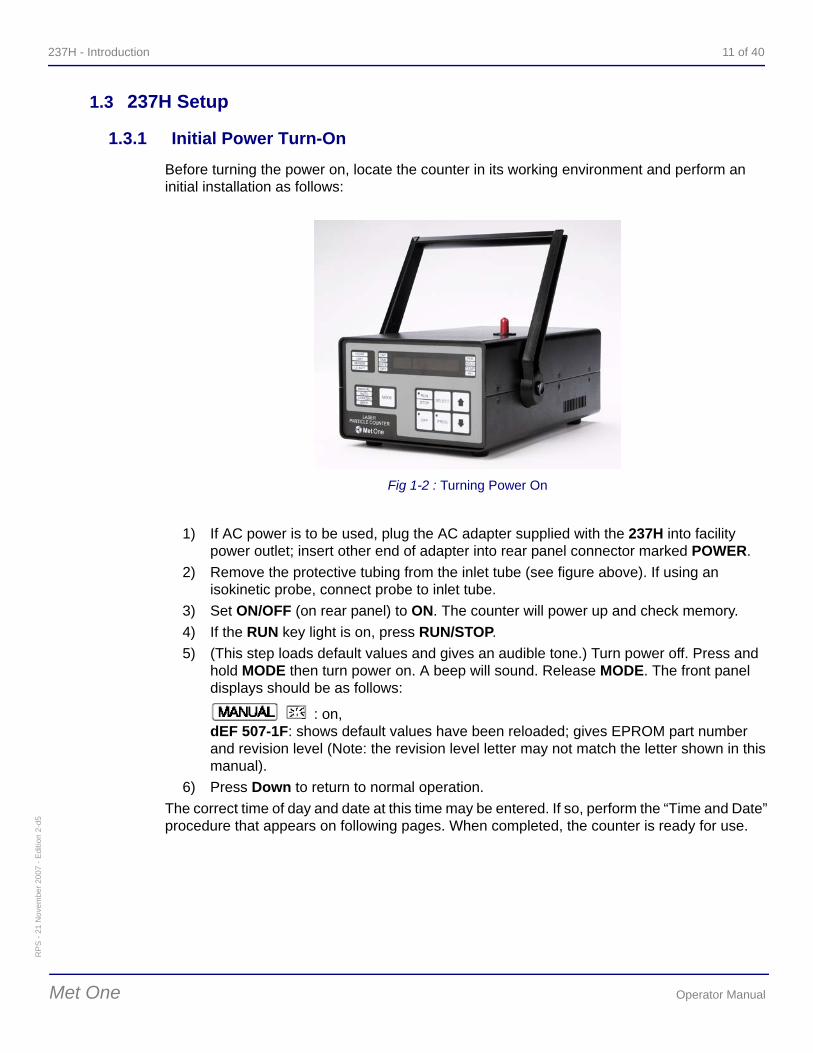
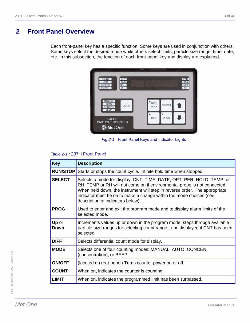
2 Front Panel Overview
Each front-panel key has a specific function. Some keys are used in conjunction with others. Some keys select the desired mode while others select limits, particle size range, time, date, etc. In this subsection, the function of each front-panel key and display are explained.
Fig 2-1 : Front Panel Keys and Indicator Lights
Table 2-1 : 237H Front Panel
Key Description
RUN/STOP Starts or stops the count cycle. Infinite hold time when stopped.
SELECT Selects a mode for display: CNT, TIME, DATE, OPT, PER, HOLD, TEMP, or RH. TEMP or RH will not come on if environmental probe is not connected. When held down, the instrument will step in reverse order. The appropriate indicator must be on to make a change within the mode choices (see description of indicators below).
PROG Used to enter and exit the program mode and to display alarm limits of the selected mode.
Up or Down
Increments values up or down in the program mode; steps through available particle-size ranges for selecting count range to be displayed if CNT has been selected.
DIFF Selects differential count mode for display.
MODE Selects one of four counting modes: MANUAL, AUTO, CONCEN (concentration), or BEEP.
ON/OFF (located on rear panel) Turns counter power on or off.
COUNT When on, indicates the counter is counting.
LIMIT When on, indicates the programmed limit has been surpassed.
14 of 40 Front Panel Overview - 237H
RP
S - 2
1 N
ovem
ber 2
007
- Edi
tion
2-d5
Operator Manual Met One
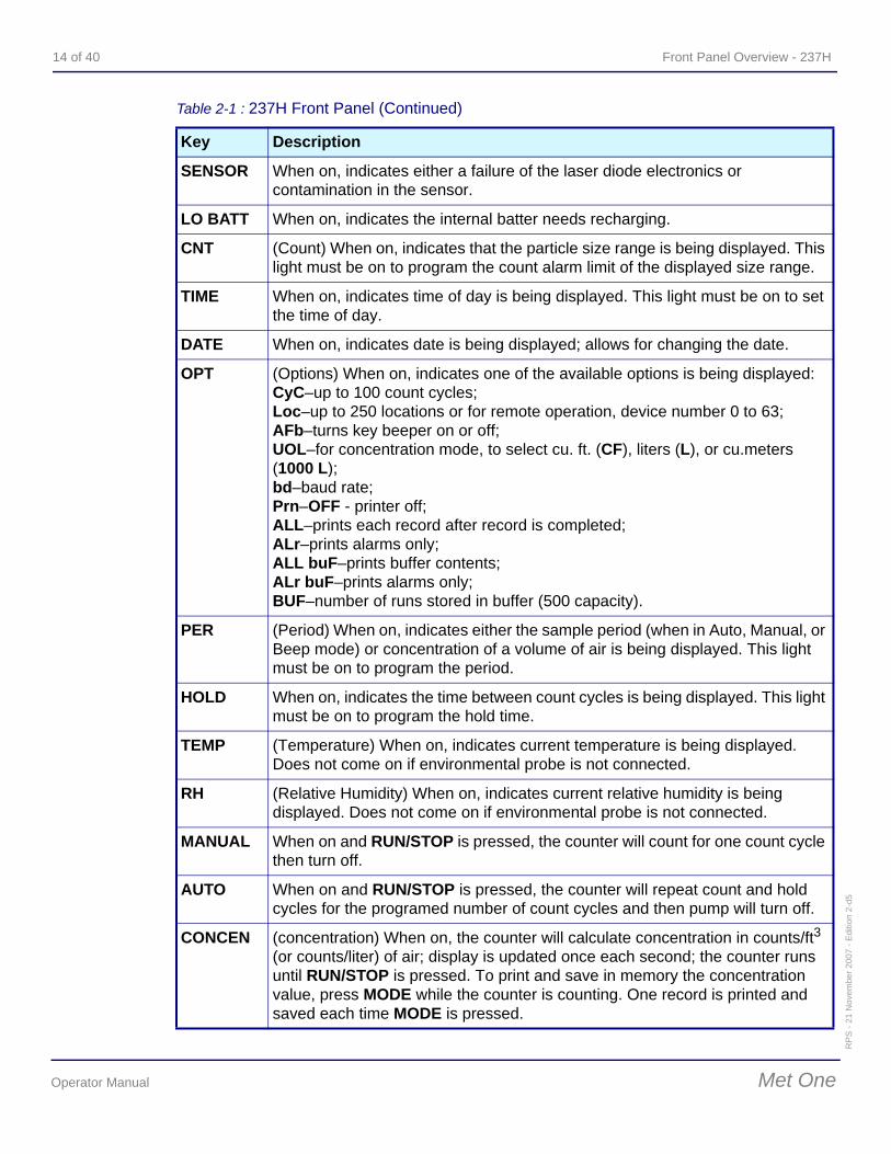
SENSOR When on, indicates either a failure of the laser diode electronics or contamination in the sensor.
LO BATT When on, indicates the internal batter needs recharging.
CNT (Count) When on, indicates that the particle size range is being displayed. This light must be on to program the count alarm limit of the displayed size range.
TIME When on, indicates time of day is being displayed. This light must be on to set the time of day.
DATE When on, indicates date is being displayed; allows for changing the date.
OPT (Options) When on, indicates one of the available options is being displayed: CyC–up to 100 count cycles; Loc–up to 250 locations or for remote operation, device number 0 to 63; AFb–turns key beeper on or off; UOL–for concentration mode, to select cu. ft. (CF), liters (L), or cu.meters (1000 L);bd–baud rate; Prn–OFF - printer off; ALL–prints each record after record is completed; ALr–prints alarms only; ALL buF–prints buffer contents; ALr buF–prints alarms only; BUF–number of runs stored in buffer (500 capacity).
PER (Period) When on, indicates either the sample period (when in Auto, Manual, or Beep mode) or concentration of a volume of air is being displayed. This light must be on to program the period.
HOLD When on, indicates the time between count cycles is being displayed. This light must be on to program the hold time.
TEMP (Temperature) When on, indicates current temperature is being displayed. Does not come on if environmental probe is not connected.
RH (Relative Humidity) When on, indicates current relative humidity is being displayed. Does not come on if environmental probe is not connected.
MANUAL When on and RUN/STOP is pressed, the counter will count for one count cycle then turn off.
AUTO When on and RUN/STOP is pressed, the counter will repeat count and hold cycles for the programed number of count cycles and then pump will turn off.
CONCEN (concentration) When on, the counter will calculate concentration in counts/ft3 (or counts/liter) of air; display is updated once each second; the counter runs until RUN/STOP is pressed. To print and save in memory the concentration value, press MODE while the counter is counting. One record is printed and saved each time MODE is pressed.
Table 2-1 : 237H Front Panel (Continued)
Key Description
237H - Front Panel Overview 15 of 40R
PS
- 21
Nov
embe
r 200
7 - E
ditio
n 2-
d5
Met One Operator Manual
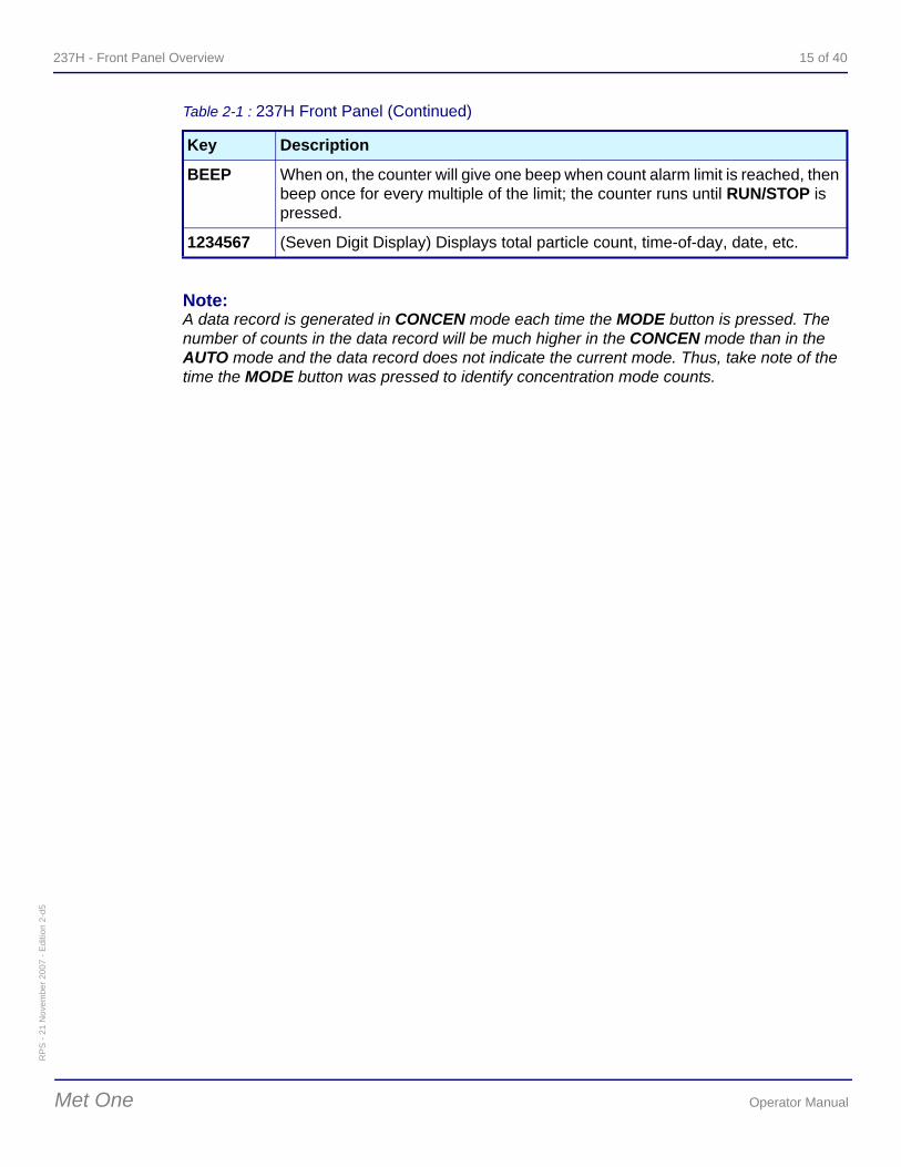
Note:A data record is generated in CONCEN mode each time the MODE button is pressed. The number of counts in the data record will be much higher in the CONCEN mode than in the AUTO mode and the data record does not indicate the current mode. Thus, take note of the time the MODE button was pressed to identify concentration mode counts.
BEEP When on, the counter will give one beep when count alarm limit is reached, then beep once for every multiple of the limit; the counter runs until RUN/STOP is pressed.
1234567 (Seven Digit Display) Displays total particle count, time-of-day, date, etc.
Table 2-1 : 237H Front Panel (Continued)
Key Description

16 of 40 Front Panel Overview - 237H
RP
S - 2
1 N
ovem
ber 2
007
- Edi
tion
2-d5
Operator Manual Met One
237H - 237H Operation 17 of 40R
PS
- 21
Nov
embe
r 200
7 - E
ditio
n 2-
d5
Met One Operator Manual
3 237H Operation
Operating functions of the counter (count alarm limits, period and hold times, etc.) are changed using front panel keys. Parameters of all the features offered in the counter can also be changed.
3.1 Time and Date
These parameters can be displayed while in either the run or stop mode by pressing the SELECT key until the TIME or DATE comes on. To change time-of-day or date, perform the following steps:
1) Turn counter on; press RUN/STOP until RUN light is off. 2) Press SELECT until TIME is on. Existing time of day will be displayed.3) Press PROG. Hours digits will blink. A 24-hour clock format is used. 4) Press SELECT until digit requiring change is blinking. 5) To increment to the next value, press Up or Down once. To scroll, press and hold either
arrow key.6) Press SELECT to enter the new value into memory; the next digit will begin blinking. To
set next digit, repeat step 5 and this step; to exit programming mode, press PROG again.
7) To change date, press SELECT until DATE is on then repeat steps 3 through 6 above.
3.2 Period and Hold Time
The period (sample time) is the desired length of time to sample air. Period can be set to any value from 0 (zero) up to (but not including) 24 hours. Hold time is the length of time between samples and can be set to any value from 1 second up to (but not including 24 hours). If the period is set to 0 (zero), the counter will count indefinitely or until RUN/STOP is pressed. In the MANUAL mode the counter counts for the period (sample time) then stops. In the AUTO mode, the sample cycles repeat for the number of times programmed under CYC (cycles). The final count value will be displayed during the hold time.
1) Turn counter on; press RUN/STOP until RUN light is off. 2) Press SELECT until PER is on. Existing period will be displayed in hours, minutes, and
seconds. 3) Press PROG; hours digits will blink. To change value, press Up or Down once. To
scroll, press and hold down either arrow key. 4) Press SELECT to enter the hours digit into memory and to select minutes digits. 5) Repeat steps 3 and 4 for minutes and seconds digits then press PROG to enter the
value for the new period. 6) To change hold time, press SELECT until HOLD is on then repeat step 3 through
step 5 above.
18 of 40 237H Operation - 237H
RP
S - 2
1 N
ovem
ber 2
007
- Edi
tion
2-d5
Operator Manual Met One
3.3 Count Alarm Limits
An audible count alarm can be set to occur when the count exceeds any number. The range is from zero (turns alarm off) up to 9,999,999. Each particle size range may have a different count alarm limit. The alarm will sound as soon as any count alarm limit is exceeded.
Note:To turn off the alarm, enter a limit value of 0 (zero) for all particle size ranges. To silence the alarm, press any key except RUN/STOP. To hear one beep when the count limit is reached and at each multiple thereafter, select the beep mode.
1) Turn counter on; press RUN/STOP until RUN light is off. 2) Press SELECT until CNT is on. Press Up or Down until particle size range to be
changed appears. 3) Press PROG. The largest digit of alarm limit will blink; press SELECT until digit
requiring change is blinking. 4) Press Up or Down once to increment to the next value. To scroll, press and hold either
arrow key. 5) Press SELECT to enter the new value into memory; the next digit will begin blinking. To
set next digit, repeat step 4 and this step. To exit programming mode, press PROG again.
6) To change count alarm limits for another particle size range, press Up or Down until desired size range is displayed then repeat step 3 through step 5 above.
3.4 Concentration (CONCEN) Mode
This mode gives a quick (within seconds) calculation of the particle concentration. The mode averages the number of particles counted in one-second periods to give the calculation of count-per-cubic-foot (or count-per-liter) of air. The displayed count is updated every second. The number of one-second periods to be averaged (from one to ten) is selected using this procedure. There is no computer serial interface capabilities while in this mode. Concentration mode results can be printed out (and stored in memory) while counting by pressing MODE. Each time a count is to be printed and stored, MODE must be pressed.
1) Turn counter on; press RUN/STOP until the RUN light is off. 2) Press MODE until CONCEN is on. 3) Press SELECT key until PER is on. (Keep in mind, the period is not being set, but the
programming concentration mode.) Existing number of periods to be averaged will be displayed.
4) Press PROG; displayed number of periods will blink. 5) To change the value, press Up or Down; press PROG to enter the value. 6) Press SELECT until CNT is on. To start counting press RUN/STOP.
Note:For example, if PER is selected and the display reads 00.00.08, this means the counter will count continuously for one-second periods, then, after eight seconds, display the calculated count-per-cubic-foot of air based on the average of the last eight periods. After each second, the oldest period's count is deleted from the average and the newest is calculated into the average and the new result is displayed.
237H - 237H Operation 19 of 40R
PS
- 21
Nov
embe
r 200
7 - E
ditio
n 2-
d5
Met One Operator Manual
3.5 Audible (BEEP) Mode
The beep mode changes the count alarm feature to a single audible sound (beep) once each time the count alarm limit is reached and then once more for every count multiple of the count limit. A beep will sound for each particle size range count limit. We therefore suggest to set a limit for only the size range of interest and set the remaining ranges to zero (no alarm). The beep mode limits and count alarm limits are one and the same.
1) Press MODE until BEEP is on. 2) The count number that was set in the Count Alarm Limits procedure will be the number
that applies also for the beep mode. To change when the audible sound occurs, perform the Count Alarm Limits procedure.
Note:The counter will count in this mode until RUN/STOP is pressed again.
3.6 Clear Rotating Buffer (BUF)
Note:Make sure the stored data is no longer needed before continuing.
Count data taken while in the AUTO and MANUAL mode are stored in the rotating buffer. To clear all data runs from the buffer, perform the following steps:
1) Press SELECT until OPT is on then press Up or Down until BUF is displayed. The number of sample runs currently stored in the buffer will appear on the readout display.
2) Press PROG; the display will go to 0 meaning no sample runs remain in the rotating buffer. Press PROG again. To change to another parameter, press SELECT.
3.7 Setting Number of Count Cycles (CYC)
The number of count cycles displayed is the number of times the counter will count before stopping. Up to 100 cycles can be made while in the AUTO mode. To count indefinitely, set the number to zero. Change the number of count cycles as follows:
1) Press SELECT until OPT is on then press Up or Down until CYC is displayed. The current number of count cycles programmed will appear on the readout display.
2) Press PROG (number will blink) then press Up or Down to select a new number of count cycles.
3) Press PROG to enter selection. To change to another parameter, press SELECT.
20 of 40 237H Operation - 237H
RP
S - 2
1 N
ovem
ber 2
007
- Edi
tion
2-d5
Operator Manual Met One
3.8 Changing Location Number (Loc)
Any number from zero to 250 can be assigned to a location. Assign a different number each time locations are changed. The number will appear on the printout and as part of the data record in the rotating buffer. During remote operation, this number applies to the device number (from 0 to 63). Refer to “Serial Port Protocol and Commands” on page 25 for more information.
1) Press SELECT until OPT is on then press Up or Down until Loc is displayed. Current location number will appear on the readout display.
2) Press PROG (number will blink) then press Up or Down for a new number. 3) Press PROG to enter selection. Press SELECT to change parameters.
3.9 Turning Beeper On or Off (AFb)
The audible feedback system (beeper) can be turned on or off except for an environmental probe LIMIT alarm, SENSOR alarm, or LO BATT alarm. Turn beeper on or off as follows:
1) Press SELECT until OPT is on then press Up or Down until AFb is displayed. The current status (on or off) of the beeper will appear on the readout display.
2) Press PROG (the status will blink) then press Up or Down to change to either OFF or ON.
3) Press PROG to enter selection. To change to another parameter, press SELECT.
3.10 Changing Volume Units for Concentration Mode (UOL)
The concentration mode provides an estimation of the counts per cubic foot (CF) or counts per liter (L). Change the units to cubic foot or to liter as follows:
1) Press SELECT until OPT is on then press Up or Down until UOL is displayed. The current units (CF or L) will appear on the readout display.
2) Press PROG key (units will blink) then press Up or Down to toggle to other choice.3) Press PROG to enter selection. To change to another parameter, press SELECT.
3.11 Setting Baud Rate (bd)
The baud rate may be set to either 300, 1200, 2400, or 9600. Set baud rate as follows:
1) Press SELECT until OPT is on then press Up or Down until bd is displayed. The current baud rate will appear on the readout display.
2) Press PROG key (existing baud rate will blink) then press Up or Down to cycle through selections; stop when the choice is displayed.
3) Press PROG to enter selection. To change to another parameter, press SELECT.
237H - 237H Operation 21 of 40R
PS
- 21
Nov
embe
r 200
7 - E
ditio
n 2-
d5
Met One Operator Manual
3.12 Changing Printer Options
The external printer will print all important count data as well as date, time, location, etc. Select the desired option as follows:
The five printer options are:
OFF—turns the printer off;
ALL—prints results after completion of each count cycle;
ALr—prints alarms only; To keep from losing data stored in memory,
ALL buF—prints the contents of the rotating buffer;
ALr buF—prints alarms in the buffer.
Note:To keep from losing data stored in memory, the printer will automatically stop printing when a low battery level is detected.
Choose printer options as follows:
1) Press SELECT until OPT is on. 2) Press UP or DOWN until Prn is displayed. The current status ("on" or "OFF") will
appear on the display. 3) Press PROG ("ALL" or "OFF" will blink) then press UP or DOWN to step through the
choices. If you select ALL buF, the printer will print the buffer contents without erasing the contents and then default to the "ALL" choice.
4) Press PROG to enter selection. To change to another parameter, press SELECT.

22 of 40 237H Operation - 237H
RP
S - 2
1 N
ovem
ber 2
007
- Edi
tion
2-d5
Operator Manual Met One
237H - Using Options and Accessories 23 of 40R
PS
- 21
Nov
embe
r 200
7 - E
ditio
n 2-
d5
Met One Operator Manual
4 Using Options and Accessories
Options can be installed when the counter is ordered or anytime thereafter when the counter is returned to the factory. Accessories can be ordered from the factory at any time.
4.1 Setting up an External Printer
CAUTION:• Before performing this procedure, load paper into the external printer (refer to printer
instruction manual). Operating the printer without paper may damage the print head.• When connecting AC adapters to printers and counter, be sure to follow the location tags
on the cables.• The counter must be turned off before connecting the external printer. Connecting the
printer while the counter is on may damage the counter.
An external printer is considered an option because output to the external printer requires installation of a Centronics parallel interface connector at the time the counter is built.
Over the years, several external printers have been available as options from the factory. The Model DPU-414 is the latest printer available and supersedes the DPU-411.
If an external printer option is used (no built-in printer), connect the printer as follows:
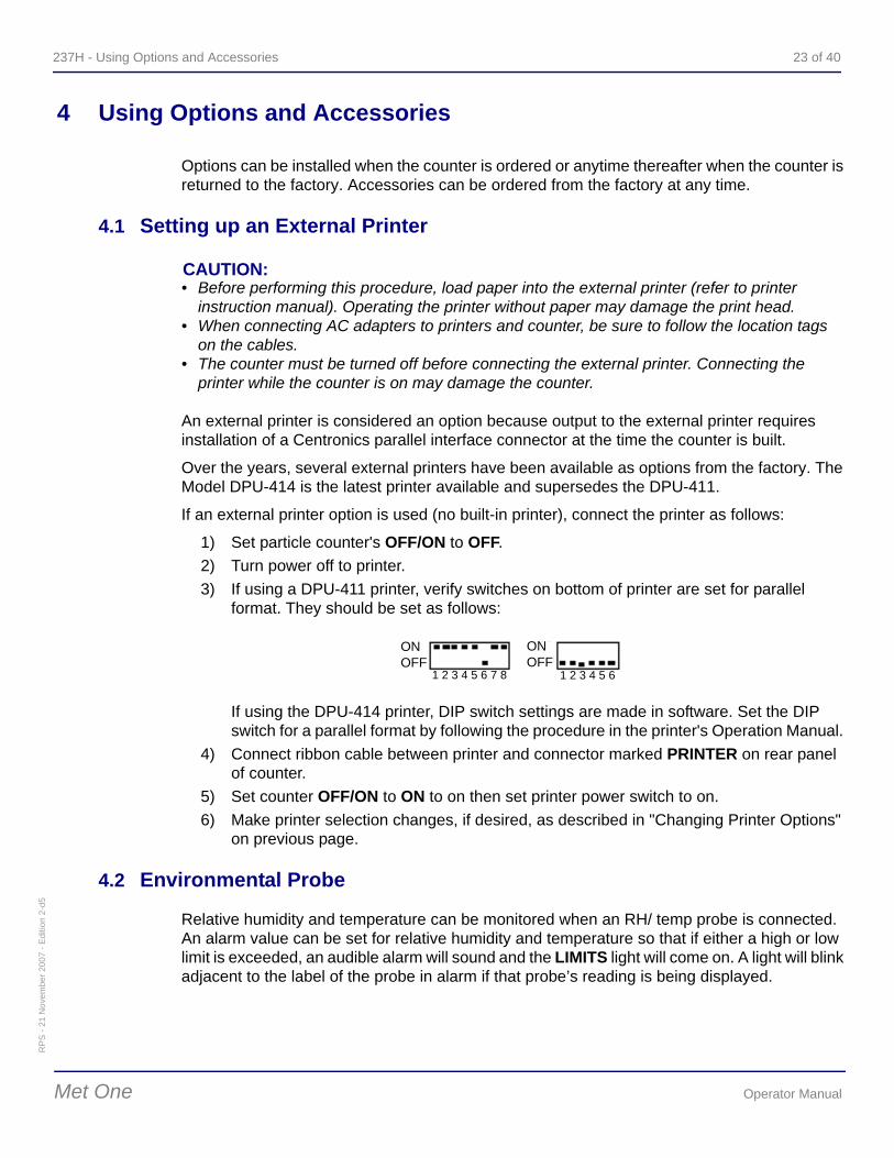
1) Set particle counter's OFF/ON to OFF. 2) Turn power off to printer. 3) If using a DPU-411 printer, verify switches on bottom of printer are set for parallel
format. They should be set as follows:
If using the DPU-414 printer, DIP switch settings are made in software. Set the DIP switch for a parallel format by following the procedure in the printer's Operation Manual.
4) Connect ribbon cable between printer and connector marked PRINTER on rear panel of counter.
5) Set counter OFF/ON to ON to on then set printer power switch to on. 6) Make printer selection changes, if desired, as described in "Changing Printer Options"
on previous page.
4.2 Environmental Probe
Relative humidity and temperature can be monitored when an RH/ temp probe is connected. An alarm value can be set for relative humidity and temperature so that if either a high or low limit is exceeded, an audible alarm will sound and the LIMITS light will come on. A light will blink adjacent to the label of the probe in alarm if that probe’s reading is being displayed.
ONOFF
ONOFF
1 2 3 4 5 6 7 8 1 2 3 4 5 6
24 of 40 Using Options and Accessories - 237H
RP
S - 2
1 N
ovem
ber 2
007
- Edi
tion
2-d5
Operator Manual Met One
Note:Alarm limits for relative humidity and temperature can only be displayed or programmed when the probe is connected to the counter.
• To silence the alarm, press any front-panel key except RUN/STOP.• To turn off the alarm, enter both an upper and lower limit value of 0 (zero).
The following tips should be noted when using the RH/temp probe:
• Never touch the sensing element of the probe; it is very fragile. • Sensing elements should not be exposed to caustic vapors (e.g., acetone, Freon, and
room temperature vulcanization (RTV)). • Keep the RH/temp probe away from exhaust fans for more accurate measurements of
temperature.• For accurate measurements of relative humidity, allow probe to stabilize several
minutes; take samples in still air. Program the probe high- and low-alarm limits as follows:
1) Connect RH/temp probe to the counter rear-panel connector marked RH/TEMP. 2) Turn counter on then press RUN/STOP until RUN light is on. 3) To read temperature or relative humidity, press SELECT until TEMP or RH is on. 4) To change the high-alarm or low-alarm limit or to change readout from °F to °C or from
°C to °F, press PROG then press SELECT until the desired display is blinking. 5) Press Up or Down to increment to the next value. To scroll, press and hold down either
arrow key. 6) Press SELECT to enter the new value into memory; the next digit will begin blinking. To
exit programming mode, press PROG. To set next digit, repeat step 5 and this step. 7) To set relative humidity alarm limits, press SELECT until RH is on then press PROG
then press SELECT again until digit requiring change is blinking; repeat step 5 and step 6 above.
237H - Serial Port Protocol and Commands 25 of 40R
PS
- 21
Nov
embe
r 200
7 - E
ditio
n 2-
d5
Met One Operator Manual
5 Serial Port Protocol and Commands
This section describes particle counter operation using a computer and the Universal Utility Software (UUS). The UUS was designed to control the counter from a computer and to upload count data into a computer.
If the UUS is not used, the information on the following pages will clarify operation of the counter with a computer. However, the “Particle Counters for Air” manual will provide more detail information on this subject.
The counter has been set up for one of two serial data communications capabilities: 1) RS-232 serial interface circuitry provides for using the UUS and a computer to control a counter, or 2) RS-485 serial network circuitry provides asynchronous communications between up to 64 counters and a controlling computer.
5.1 Serial Cables
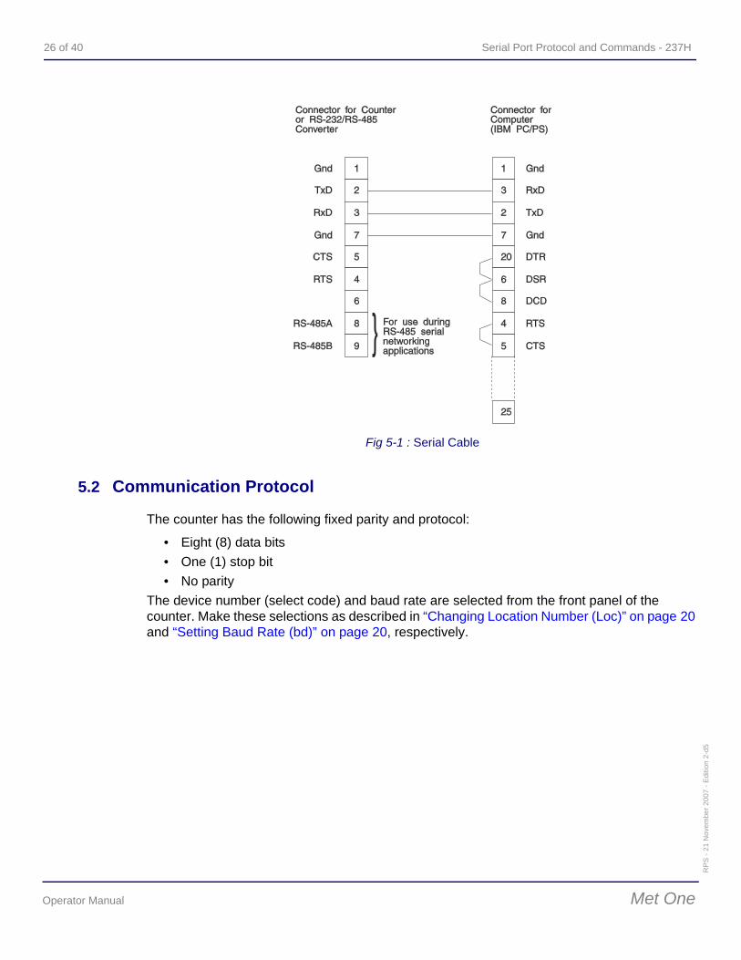
All counters are connected to a computer with a serial cable. The use of a serial cable between the computer and counter allows for RS232 operation; an RS-485 serial cable between computer's 8-port serial I/O board and the first counter allows for multiple counter operations. The cabling diagram below is provided for those who wish to make their own custom-length cable.
CAUTION:To avoid internal circuit board damage, configure the cable as shown in Figure 5-1 which shows wiring for a 25-pin connector on the computer. If the computer is a nine-pin type, use a 9-pin to 25-pin adapter cable. Both cables are available from Hach Ultra.
26 of 40 Serial Port Protocol and Commands - 237H
RP
S - 2
1 N
ovem
ber 2
007
- Edi
tion
2-d5
Operator Manual Met One
5.2 Communication Protocol
The counter has the following fixed parity and protocol:
• Eight (8) data bits • One (1) stop bit • No parity
The device number (select code) and baud rate are selected from the front panel of the counter. Make these selections as described in “Changing Location Number (Loc)” on page 20 and “Setting Baud Rate (bd)” on page 20, respectively.
Fig 5-1 : Serial Cable
237H - Serial Port Protocol and Commands 27 of 40R
PS
- 21
Nov
embe
r 200
7 - E
ditio
n 2-
d5
Met One Operator Manual
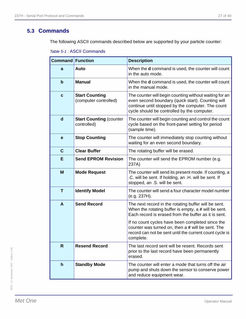
5.3 Commands
The following ASCII commands described below are supported by your particle counter:
Table 5-1 : ASCII Commands
Command Function Description
a Auto When the d command is used, the counter will count in the auto mode.
b Manual When the d command is used, the counter will count in the manual mode.
c Start Counting(computer controlled)
The counter will begin counting without waiting for an even second boundary (quick start). Counting will continue until stopped by the computer. The count cycle should be controlled by the computer.
d Start Counting (counter controlled)
The counter will begin counting and control the count cycle based on the front-panel setting for period (sample time).
e Stop Counting The counter will immediately stop counting without waiting for an even second boundary.
C Clear Buffer The rotating buffer will be erased.
E Send EPROM Revision The counter will send the EPROM number (e.g. 237A)
M Mode Request The counter will send its present mode. If counting, a .C. will be sent. If holding, an .H. will be sent. If stopped, an .S. will be sent.
T Identify Model The counter will send a four character model number (e.g. 237H).
A Send Record The next record in the rotating buffer will be sent. When the rotating buffer is empty, a # will be sent. Each record is erased from the buffer as it is sent.
If no count cycles have been completed since the counter was turned on, then a # will be sent. The record can not be sent until the current count cycle is complete.
R Resend Record The last record sent will be resent. Records sent prior to the last record have been permanently erased.
h Standby Mode The counter will enter a mode that turns off the air pump and shuts down the sensor to conserve power and reduce equipment wear.
28 of 40 Serial Port Protocol and Commands - 237H
RP
S - 2
1 N
ovem
ber 2
007
- Edi
tion
2-d5
Operator Manual Met One
Note:Do not use the Universal Select command when more than one counter is on the same serial port because more than one counter will respond at the same time, causing communication problems.
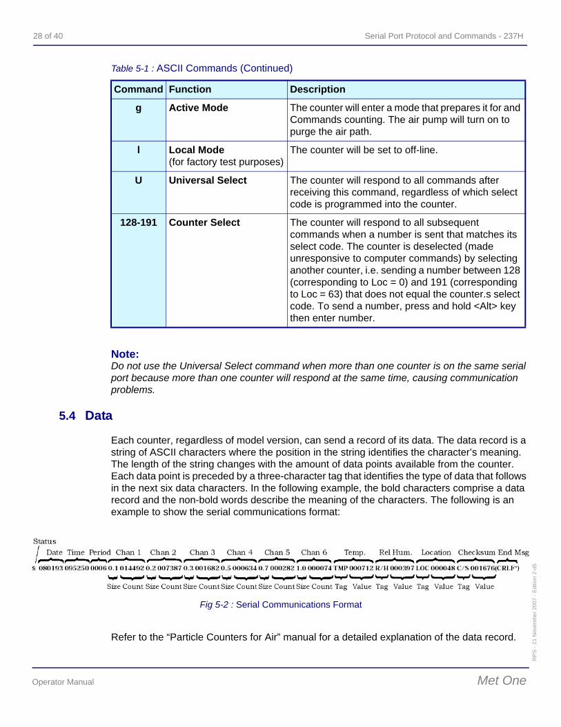
5.4 Data
Each counter, regardless of model version, can send a record of its data. The data record is a string of ASCII characters where the position in the string identifies the character’s meaning. The length of the string changes with the amount of data points available from the counter. Each data point is preceded by a three-character tag that identifies the type of data that follows in the next six data characters. In the following example, the bold characters comprise a data record and the non-bold words describe the meaning of the characters. The following is an example to show the serial communications format:
Refer to the “Particle Counters for Air” manual for a detailed explanation of the data record.
g Active Mode The counter will enter a mode that prepares it for and Commands counting. The air pump will turn on to purge the air path.
l Local Mode (for factory test purposes)
The counter will be set to off-line.
U Universal Select The counter will respond to all commands after receiving this command, regardless of which select code is programmed into the counter.
128-191 Counter Select The counter will respond to all subsequent commands when a number is sent that matches its select code. The counter is deselected (made unresponsive to computer commands) by selecting another counter, i.e. sending a number between 128 (corresponding to Loc = 0) and 191 (corresponding to Loc = 63) that does not equal the counter.s select code. To send a number, press and hold <Alt> key then enter number.
Table 5-1 : ASCII Commands (Continued)
Command Function Description
Fig 5-2 : Serial Communications Format
237H - Specifications 29 of 40R
PS
- 21
Nov
embe
r 200
7 - E
ditio
n 2-
d5
Met One Operator Manual
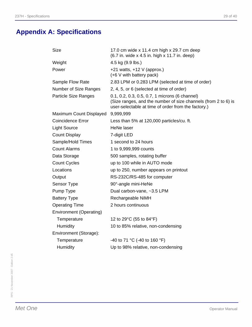
Appendix A: Specifications
Size 17.0 cm wide x 11.4 cm high x 29.7 cm deep (6.7 in. wide x 4.5 in. high x 11.7 in. deep)
Weight 4.5 kg (9.9 lbs.)Power +21 watts, +12 V (approx.)
(+6 V with battery pack)Sample Flow Rate 2.83 LPM or 0.283 LPM (selected at time of order) Number of Size Ranges 2, 4, 5, or 6 (selected at time of order) Particle Size Ranges 0.1, 0.2, 0.3, 0.5, 0.7, 1 microns (6 channel)
(Size ranges, and the number of size channels (from 2 to 6) is user-selectable at time of order from the factory.)
Maximum Count Displayed 9,999,999 Coincidence Error Less than 5% at 120,000 particles/cu. ft. Light Source HeNe laser Count Display 7-digit LED Sample/Hold Times 1 second to 24 hours Count Alarms 1 to 9,999,999 counts Data Storage 500 samples, rotating buffer Count Cycles up to 100 while in AUTO mode Locations up to 250, number appears on printout Output RS-232C/RS-485 for computer Sensor Type 90°-angle mini-HeNe Pump Type Dual carbon-vane, ~3.5 LPMBattery Type Rechargeable NiMHOperating Time 2 hours continuous Environment (Operating)
Temperature 12 to 29°C (55 to 84°F) Humidity 10 to 85% relative, non-condensing
Environment (Storage): Temperature -40 to 71 °C (-40 to 160 °F) Humidity Up to 98% relative, non-condensing
30 of 40 Specifications - 237H
RP
S - 2
1 N
ovem
ber 2
007
- Edi
tion
2-d5
Operator Manual Met One
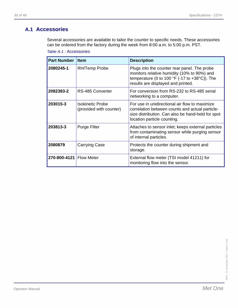
A.1 Accessories
Several accessories are available to tailor the counter to specific needs. These accessories can be ordered from the factory during the week from 8:00 a.m. to 5:00 p.m. PST. Table A-1 : Accessories
Part Number Item Description
2080245-1 RH/Temp Probe Plugs into the counter rear panel. The probe monitors relative humidity (10% to 90%) and temperature (0 to 100 °F (-17 to +38°C)). The results are displayed and printed.
2082383-2 RS-485 Converter For conversion from RS-232 to RS-485 serial networking to a computer.
203015-3 Isokinetic Probe (provided with counter)
For use in unidirectional air flow to maximize correlation between counts and actual particle-size distribution. Can also be hand-held for spot location particle counting.
203813-3 Purge Filter Attaches to sensor inlet; keeps external particles from contaminating sensor while purging sensor of internal particles.
2080879 Carrying Case Protects the counter during shipment and storage.
270-800-4121 Flow Meter External flow meter (TSI model 41211) for monitoring flow into the sensor.
237H - Technical Data 31 of 40R
PS
- 21
Nov
embe
r 200
7 - E
ditio
n 2-
d5
Met One Operator Manual
Appendix B: Technical Data
B.1 Recharging the Battery Pack
The built-in +6 V battery pack will run the counter in the portable mode, including printing results, for about two hours when in the AUTO mode, or more than two hours in the MANUAL mode. The battery pack needs recharging when LO BATT comes on. Recharge the battery pack as follows:
1) Turn counter off. 2) Plug AC adapter marked 237H into AC outlet; insert other end of adapter into rear-
panel connector marked PWR. 3) Allow counter battery pack to recharge overnight. A minimum of 16 hours is required for
total charge (when not using counter). 4) Disconnect AC adapter.
Note:The counter may be used for particle counting during recharging, however the charging rate becomes much slower.
B.2 Resetting the Counter
CAUTION:All stored sample data will be cleared when the counter is reset. All programmed functions (time and date, count alarm limits, etc.) will also be cleared and reset to the factory default settings.
This procedure clears the counter memory and restarts its microprocessor. Reset the counter as follows:
1) Set ON/OFF to OFF. 2) Press and hold MODE then set ON/OFF to ON. 3) When an audible beep sounds, release MODE. The front panel displays should be as
follows: dEF 507-1F: shows default values have been reloaded; gives EPROM part number and revision level (Note: the revision level letter may not match the letter shown in this manual).
: on,4) Press Down then reenter programmed functions.
Note:If the results in step 3 do not occur, disconnect any external equipment (RH/ Temp probe, external printer) and repeat this procedure. Reconnect one piece of equipment and repeat procedure to determine which piece of external equipment is the source of the problem.

32 of 40 Technical Data - 237H
RP
S - 2
1 N
ovem
ber 2
007
- Edi
tion
2-d5
Operator Manual Met One
237H - Declaration of Conformity 33 of 40R
PS
- 21
Nov
embe
r 200
7 - E
ditio
n 2-
d5
Met One Operator Manual
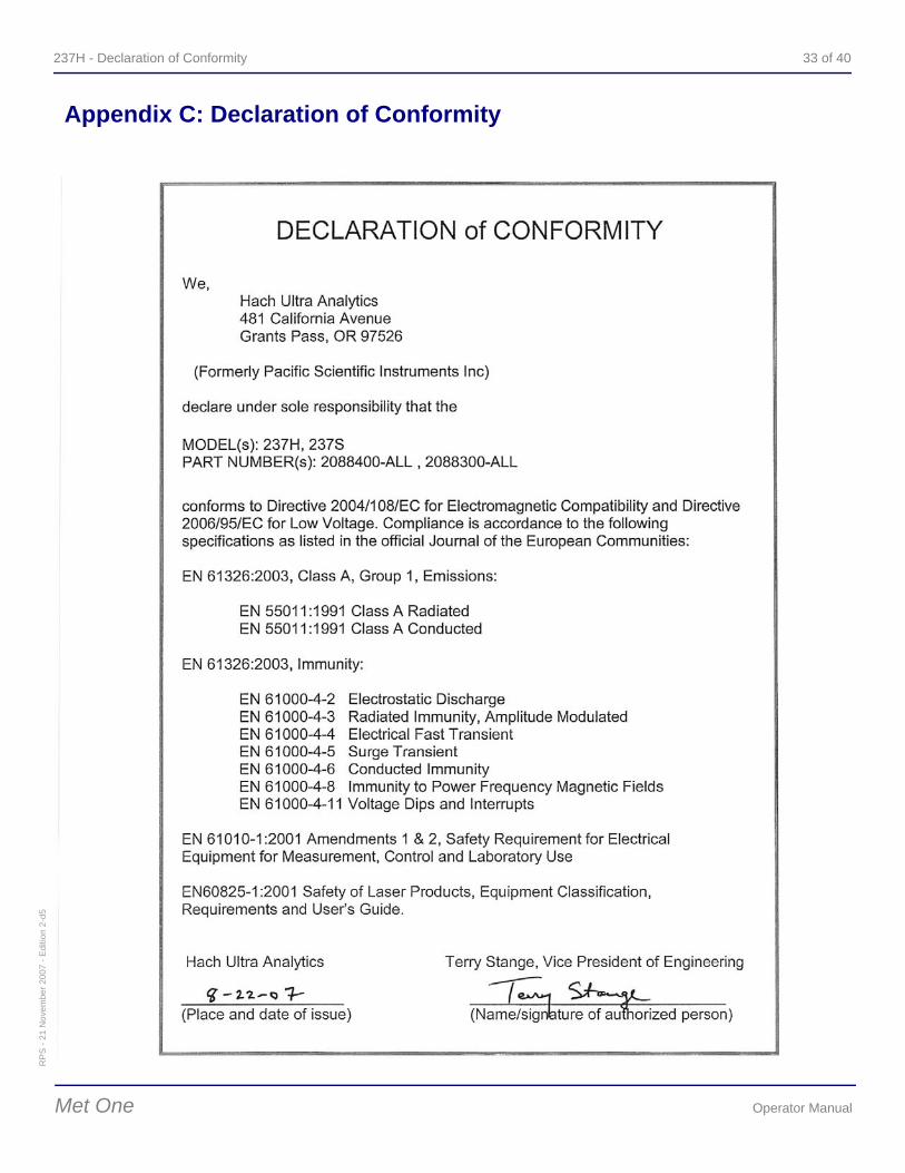
Appendix C: Declaration of Conformity

34 of 40 Declaration of Conformity - 237H
RP
S - 2
1 N
ovem
ber 2
007
- Edi
tion
2-d5
Operator Manual Met One
237H - Service Procedures 35 of 40R
PS
- 21
Nov
embe
r 200
7 - E
ditio
n 2-
d5
Met One Operator Manual
Appendix D: Service Procedures
D.1 Return Procedures
To return the 237H Airborne Particle Counter for service, first obtain a returned material authorization number (RA#). The RA# is necessary for any instrument that requires repair or calibration by an authorized service center. Include the RA# on the shipping label when the instrument is returned.
While the RA# process is described in this section, for the most up-to-date RA# process information, including copies of all required forms, call Hach Ultra at 800.866.7889 or +1 541.472.6500.
To return an instrument for credit, please contact the local sales representative.
WARNINGThe following actions must be performed when returning any unit for any reason to prevent personal injury and/or damage to the unit.
• Before shipping or storing the unit, run a test without attaching a sample vial to purge the unit of all liquid.
• All analyzers returned for repair or replacement must be thoroughly cleaned with all process material removed.
• Sludge contains bacteria that could be hazardous to Hach Ultra personnel. If a contaminated unit is received, Hach Ultra reserves the right to have the unit removed and destroyed by a hazardous material disposal team at the shipper’s expense.
D.2 Technical Support Information
Technical Support Engineers are available to provide high quality advice and recommendations for applications, product operation, measurement specifications, hardware and software, factory and customer site training.
Please provide name, company, phone, fax, model number, serial number and comment or question.
Call +1 (541) 472-6500Toll Free (800) 866-8854 (US/CA)Fax +1 (541) 474-74146:00 AM to 5:00 PM Pacific TimeMonday through FridayEmail: [email protected]

36 of 40 Service Procedures - 237H
RP
S - 2
1 N
ovem
ber 2
007
- Edi
tion
2-d5
Operator Manual Met One
237H - Annex 37 of 40R
PS
- 21
Nov
embe
r 200
7 - E
ditio
n 2-
d5
Met One Operator Manual
Annex
Tables and illustrationsFig 1-1: 237H Airborne Particle Counter .......................................................... 9Fig 1-2: Turning Power On ............................................................................. 11Fig 2-1: Front Panel Keys and Indicator Lights .............................................. 13Table 2-1: 237H Front Panel .............................................................................. 13Fig 5-1: Serial Cable....................................................................................... 26Table 5-1: ASCII Commands.............................................................................. 27Fig 5-2: Serial Communications Format ......................................................... 28Table A-1: Accessories ....................................................................................... 30

38 of 40 Annex - 237H
RP
S - 2
1 N
ovem
ber 2
007
- Edi
tion
2-d5
Operator Manual Met One
237H - User Notes 39 of 40R
PS
- 21
Nov
embe
r 200
7 - E
ditio
n 2-
d5
Met One Operator Manual
User Notes
40 of 40 User Notes - 237H
RP
S - 2
1 N
ovem
ber 2
007
- Edi
tion
2-d5
Operator Manual Met One
end of the book


Global Headquarters6, route de Compois C.P. 212CH-1222 Vesenaz, Geneva, SwitzerlandTel +41 (0)22 594 64 00 Fax +41 (0)22 594 64 99
americas Headquarters481 California AvenueGrants Pass, Oregon 97526 USATel 1 800 866 7889 / +1 541 472 6500 Fax +1 541 472 6170
www.hachultra.com
© 2007 Hach Ultra Analytics, Inc. All rights reserved. Trademarks are property of their respective owners. Specifications are subject to change without notice.


